23
Accelerate FPGA Prototyping with MATLAB and Simulink MATLAB and Simulink S t b 21 st 2010 September 21 st 2010 Stephan van Beek Senior Application Engineer 1
Accelerate FPGA Prototyping with MATLAB and SimulinkMATLAB and Simulink
S t b 21st 2010September 21st 2010
Stephan van BeekSenior Application Engineer
1
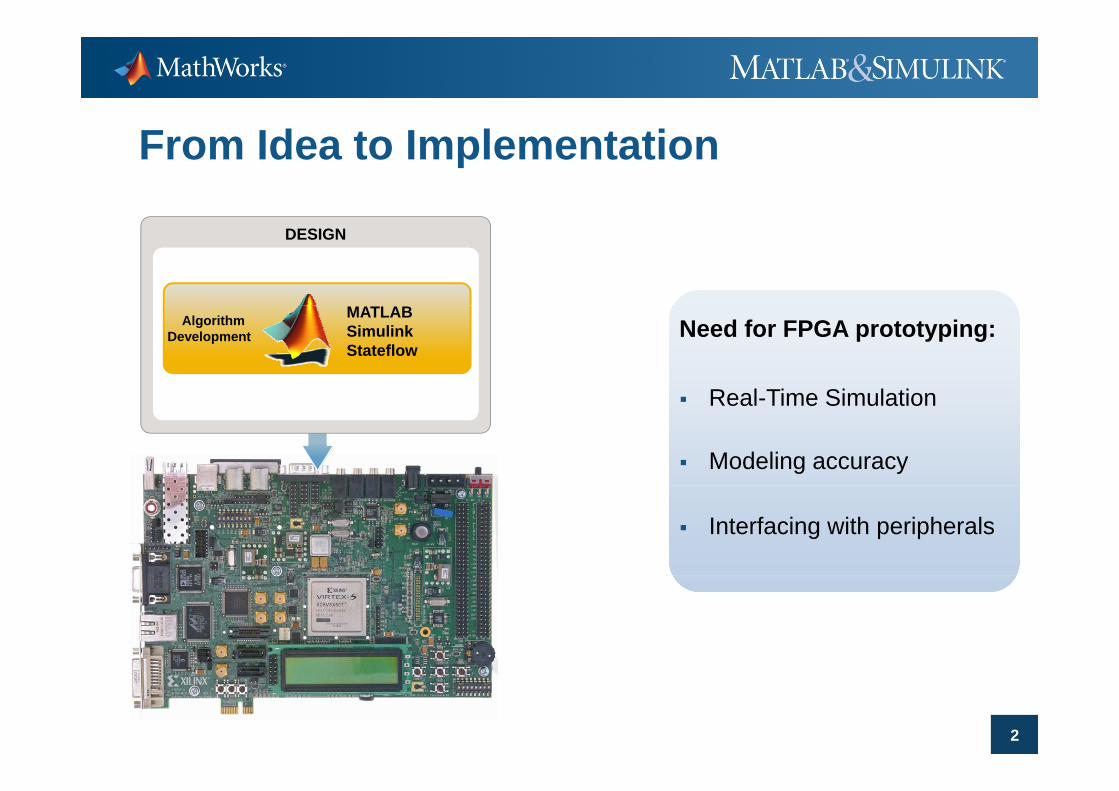
From Idea to Implementation
DESIGN
AlgorithmDevelopment
MATLABSimulinkStateflow
Need for FPGA prototyping:
Real Time Simulation Real-Time Simulation
Modeling accuracy
Interfacing with peripherals
2

Key Takeaways
Automation of manual steps in FPGA prototyping allowing shorter iteration cycles
Integration of FPGA development tools enhances verificationverification
A t ti HDL C d ti b d t d Automatic HDL Code generation can be adapted to meet your requirement
3

From Idea to Implementation (manual)
DESIGN
AlgorithmDevelopment
MATLABSimulinkStateflow
Fixed Point Conversion
HDL Code Creation HDL Code Creation
HDL Verification
FPGA Prototyping
4

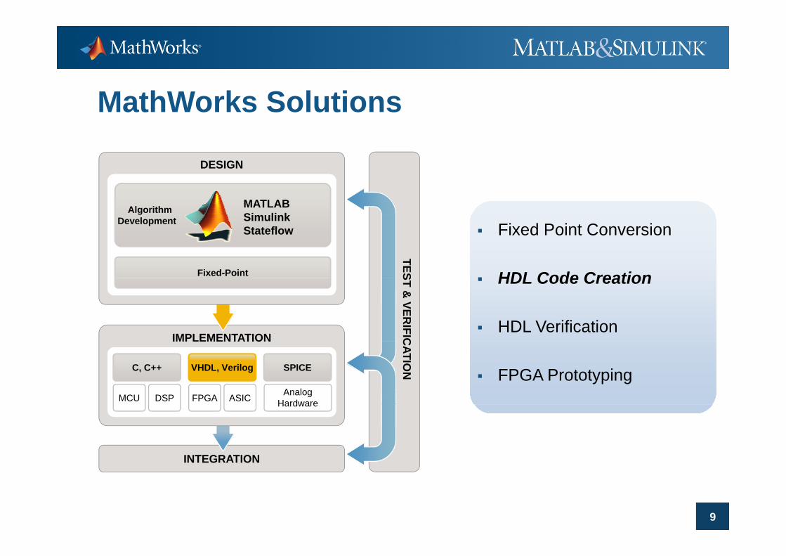
MathWorks Solutions
DESIGN
Algorithm MATLABSi li k
TESFixed-Point
Development SimulinkStateflow Fixed Point Conversion
HDL Code Creation
IMPLEMENTATION
ST & VER
IFIC
HDL Code Creation
HDL VerificationIMPLEMENTATION C
ATION
MCU DSP FPGA ASIC
VHDL, VerilogC, C++ SPICE
AnalogHardware
FPGA Prototyping
INTEGRATION
Hardware
5

MathWorks Solutions
DESIGN
Algorithm MATLABSi li k
TESFixed-Point
Development SimulinkStateflow Fixed Point Conversion
HDL Code Creation
IMPLEMENTATION
ST & VER
IFIC
HDL Code Creation
HDL VerificationIMPLEMENTATION C
ATION
MCU DSP FPGA ASIC
VHDL, VerilogC, C++ SPICE
AnalogHardware
FPGA Prototyping
INTEGRATION
Hardware
6

How to Handle Fixed-Point Conversion?
MATLABMATLABSimulink Pi = 3.141592653589793…
Stateflow Pi = 3.141601562500000Signed, 14-bits, 11 bits fraction Resources? Resources? Overflow? Precision? Error=8.9089e-6
FPGA Pi = 01100100100010
MathWorks solution:Fi d P i t T l
7
Fixed-Point Tools
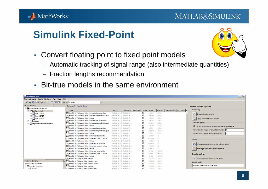
Simulink Fixed-Point
Convert floating point to fixed point models– Automatic tracking of signal range (also intermediate quantities)
Fraction lengths recommendation– Fraction lengths recommendation
Bit-true models in the same environment
8
MathWorks Solutions
DESIGN
Algorithm MATLABSi li k
TES
Development SimulinkStateflow
Fixed-Point
Fixed Point Conversion
HDL Code Creation
IMPLEMENTATION
ST & VER
IFIC
HDL Code Creation
HDL VerificationIMPLEMENTATION C
ATION
MCU DSP FPGA ASIC
C, C++ SPICE
AnalogHardware
VHDL, Verilog FPGA Prototyping
INTEGRATION
Hardware
9
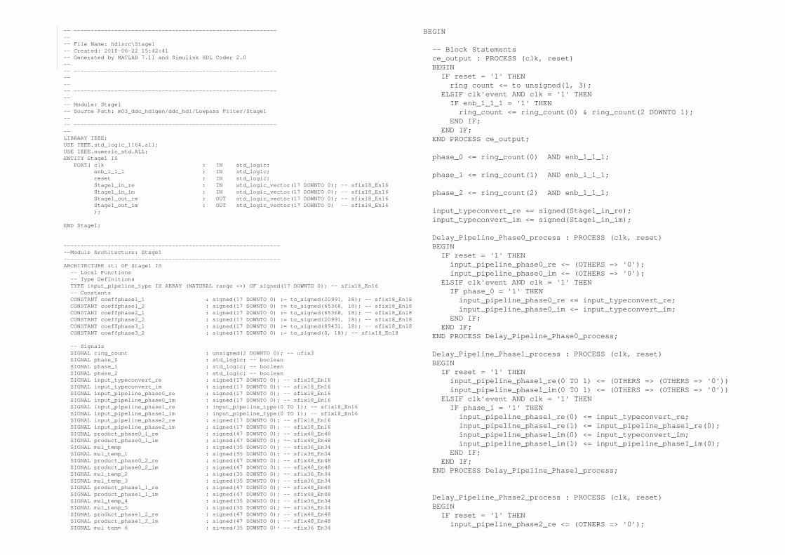
-- ---------------------------------------------------------------- File Name: hdlsrc\Stage1-- Created: 2010-06-22 15:42:41-- Generated by MATLAB 7.11 and Simulink HDL Coder 2.0---- ----------------------------------------------------------------
BEGIN
-- Block Statementsce_output : PROCESS (clk, reset)BEGINIF reset = '1' THENring count <= to unsigned(1, 3);
-- ---------------------------------------------------------------- Module: Stage1-- Source Path: m03_ddc_hdlgen/ddc_hdl/Lowpass Filter/Stage1---- --------------------------------------------------------------LIBRARY IEEE;USE IEEE.std_logic_1164.all;USE IEEE numeric std ALL;
g_ _ gELSIF clk'event AND clk = '1' THENIF enb_1_1_1 = '1' THENring_count <= ring_count(0) & ring_count(2 DOWNTO 1);
END IF;END IF;
END PROCESS ce_output;
USE IEEE.numeric_std.ALL;ENTITY Stage1 IS
PORT( clk : IN std_logic; enb_1_1_1 : IN std_logic; reset : IN std_logic; Stage1_in_re : IN std_logic_vector(17 DOWNTO 0); -- sfix18_En16Stage1_in_im : IN std_logic_vector(17 DOWNTO 0); -- sfix18_En16Stage1_out_re : OUT std_logic_vector(17 DOWNTO 0); -- sfix18_En16Stage1_out_im : OUT std_logic_vector(17 DOWNTO 0) -- sfix18_En16);
phase_0 <= ring_count(0) AND enb_1_1_1;
phase_1 <= ring_count(1) AND enb_1_1_1;
phase_2 <= ring_count(2) AND enb_1_1_1;
input_typeconvert_re <= signed(Stage1_in_re);
END Stage1;
------------------------------------------------------------------Module Architecture: Stage1----------------------------------------------------------------ARCHITECTURE rtl OF Stage1 IS-- Local Functions
T D fi iti
_ _ _ _input_typeconvert_im <= signed(Stage1_in_im);
Delay_Pipeline_Phase0_process : PROCESS (clk, reset)BEGINIF reset = '1' THENinput_pipeline_phase0_re <= (OTHERS => '0');input_pipeline_phase0_im <= (OTHERS => '0');
-- Type DefinitionsTYPE input_pipeline_type IS ARRAY (NATURAL range <>) OF signed(17 DOWNTO 0); -- sfix18_En16-- ConstantsCONSTANT coeffphase1_1 : signed(17 DOWNTO 0) := to_signed(20991, 18); -- sfix18_En18CONSTANT coeffphase1_2 : signed(17 DOWNTO 0) := to_signed(65368, 18); -- sfix18_En18CONSTANT coeffphase2_1 : signed(17 DOWNTO 0) := to_signed(65368, 18); -- sfix18_En18CONSTANT coeffphase2_2 : signed(17 DOWNTO 0) := to_signed(20991, 18); -- sfix18_En18CONSTANT coeffphase3_1 : signed(17 DOWNTO 0) := to_signed(89431, 18); -- sfix18_En18CONSTANT coeffphase3_2 : signed(17 DOWNTO 0) := to_signed(0, 18); -- sfix18_En18
ELSIF clk'event AND clk = '1' THENIF phase_0 = '1' THENinput_pipeline_phase0_re <= input_typeconvert_re;input_pipeline_phase0_im <= input_typeconvert_im;
END IF;END IF;
END PROCESS Delay_Pipeline_Phase0_process;-- SignalsSIGNAL ring_count : unsigned(2 DOWNTO 0); -- ufix3SIGNAL phase_0 : std_logic; -- booleanSIGNAL phase_1 : std_logic; -- booleanSIGNAL phase_2 : std_logic; -- booleanSIGNAL input_typeconvert_re : signed(17 DOWNTO 0); -- sfix18_En16SIGNAL input_typeconvert_im : signed(17 DOWNTO 0); -- sfix18_En16SIGNAL input_pipeline_phase0_re : signed(17 DOWNTO 0); -- sfix18_En16SIGNAL input_pipeline_phase0_im : signed(17 DOWNTO 0); -- sfix18_En16
Delay_Pipeline_Phase1_process : PROCESS (clk, reset)BEGINIF reset = '1' THENinput_pipeline_phase1_re(0 TO 1) <= (OTHERS => (OTHERS => '0'))input_pipeline_phase1_im(0 TO 1) <= (OTHERS => (OTHERS => '0'))
ELSIF clk'event AND clk = '1' THENSIGNAL input_pipeline_phase1_re : input_pipeline_type(0 TO 1); -- sfix18_En16SIGNAL input_pipeline_phase1_im : input_pipeline_type(0 TO 1); -- sfix18_En16SIGNAL input_pipeline_phase2_re : signed(17 DOWNTO 0); -- sfix18_En16SIGNAL input_pipeline_phase2_im : signed(17 DOWNTO 0); -- sfix18_En16SIGNAL product_phase0_1_re : signed(47 DOWNTO 0); -- sfix48_En48SIGNAL product_phase0_1_im : signed(47 DOWNTO 0); -- sfix48_En48SIGNAL mul_temp : signed(35 DOWNTO 0); -- sfix36_En34SIGNAL mul_temp_1 : signed(35 DOWNTO 0); -- sfix36_En34SIGNAL product_phase0_2_re : signed(47 DOWNTO 0); -- sfix48_En48SIGNAL product phase0 2 im : signed(47 DOWNTO 0); sfix48 En48
IF phase_1 = '1' THENinput_pipeline_phase1_re(0) <= input_typeconvert_re;input_pipeline_phase1_re(1) <= input_pipeline_phase1_re(0);input_pipeline_phase1_im(0) <= input_typeconvert_im;input_pipeline_phase1_im(1) <= input_pipeline_phase1_im(0);
END IF;END IF;
10
SIGNAL product_phase0_2_im : signed(47 DOWNTO 0); -- sfix48_En48SIGNAL mul_temp_2 : signed(35 DOWNTO 0); -- sfix36_En34SIGNAL mul_temp_3 : signed(35 DOWNTO 0); -- sfix36_En34SIGNAL product_phase1_1_re : signed(47 DOWNTO 0); -- sfix48_En48SIGNAL product_phase1_1_im : signed(47 DOWNTO 0); -- sfix48_En48SIGNAL mul_temp_4 : signed(35 DOWNTO 0); -- sfix36_En34SIGNAL mul_temp_5 : signed(35 DOWNTO 0); -- sfix36_En34SIGNAL product_phase1_2_re : signed(47 DOWNTO 0); -- sfix48_En48SIGNAL product_phase1_2_im : signed(47 DOWNTO 0); -- sfix48_En48SIGNAL mul temp 6 : signed(35 DOWNTO 0); -- sfix36 En34
END PROCESS Delay_Pipeline_Phase1_process;
Delay_Pipeline_Phase2_process : PROCESS (clk, reset)BEGINIF reset = '1' THENinput_pipeline_phase2_re <= (OTHERS => '0');
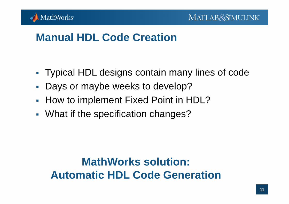
Manual HDL Code Creation
Typical HDL designs contain many lines of code Days or maybe weeks to develop? How to implement Fixed Point in HDL?How to implement Fixed Point in HDL? What if the specification changes?
MathWorks solution:A t ti HDL C d G ti
11
Automatic HDL Code Generation
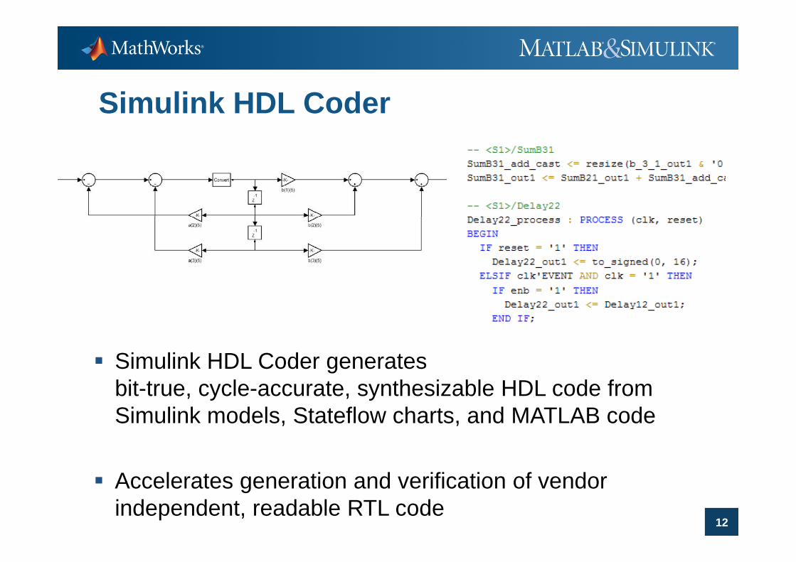
Simulink HDL Coder
Simulink HDL Coder generates bit-true, cycle-accurate, synthesizable HDL code from Si li k d l St t fl h t d MATLAB dSimulink models, Stateflow charts, and MATLAB code
A l i d ifi i f d
12
Accelerates generation and verification of vendor independent, readable RTL code

MathWorks Solutions
DESIGN
Algorithm MATLABSi li k
TES
Development SimulinkStateflow
Fixed-Point
Fixed Point Conversion
HDL Code Creation
IMPLEMENTATION
ST & VER
IFIC
HDL Code Creation
HDL VerificationIMPLEMENTATION C
ATION
MCU DSP FPGA ASIC
C, C++ SPICE
AnalogHardware
VHDL, Verilog FPGA Prototyping
INTEGRATION
Hardware
13

HDL Verification
Design the Test Bench twice10 t 1 ti f T t b h LOC t D i LOC– 10-to-1 ratio of Test bench LOC – to – Design LOC
Many stimuli-files from MATLAB These are ideal references which require pre- and
post-processing How to analyze results?
MathWorks solution:R U S t L l T tb h
14
Re-Use System Level Testbench

Co-Simulation with HDL Simulator
15

Co-Simulation with HDL Simulator
Re-use of MATLAB/Simulink testbench Extended analysis capabilities Dynamic Testbench (closed loop verification, multi domain) Automatic creation of co-simulation models
16
Integrating handwritten HDL code

MathWorks Solutions
DESIGN
Algorithm MATLABSi li k
TES
Development SimulinkStateflow
Fixed-Point
Fixed Point Conversion
HDL Code Creation
IMPLEMENTATION
ST & VER
IFIC
HDL Code Creation
HDL VerificationIMPLEMENTATION C
ATION
MCU DSP
C, C++ SPICE
AnalogHardware
VHDL, Verilog
FPGA ASIC
FPGA Prototyping
INTEGRATION
Hardware
17
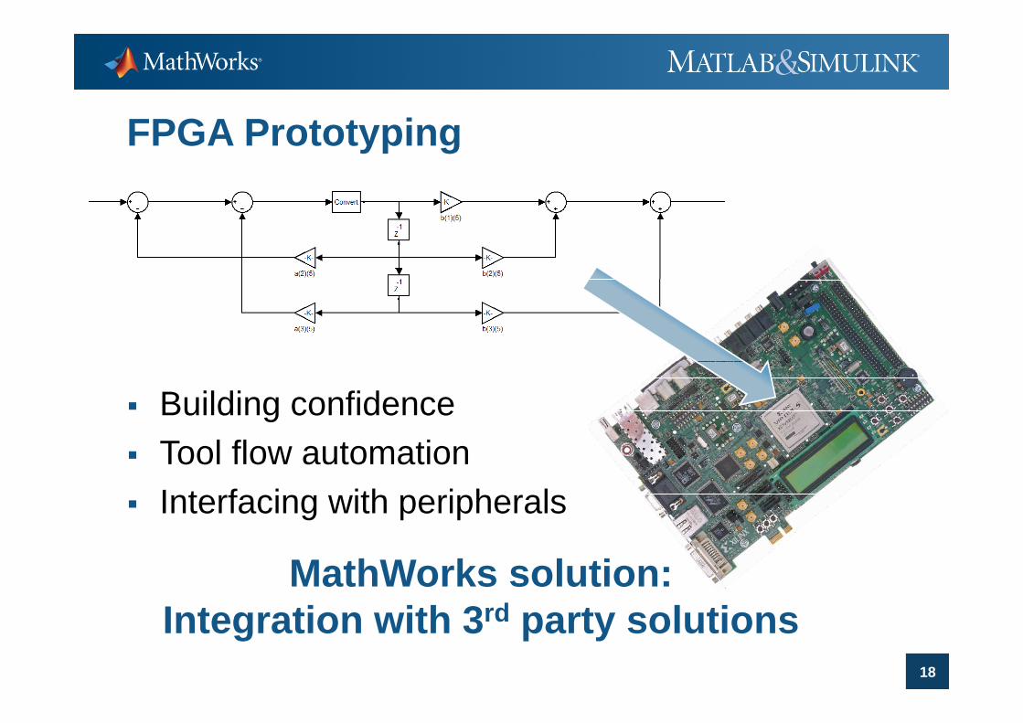
FPGA Prototyping
Building confidenceT l fl t ti Tool flow automation
Interfacing with peripherals
MathWorks solution:I t ti ith 3rd t l ti
18
Integration with 3rd party solutions

FPGA-in-the-Loop Simulation
FPGA development board
19
development board
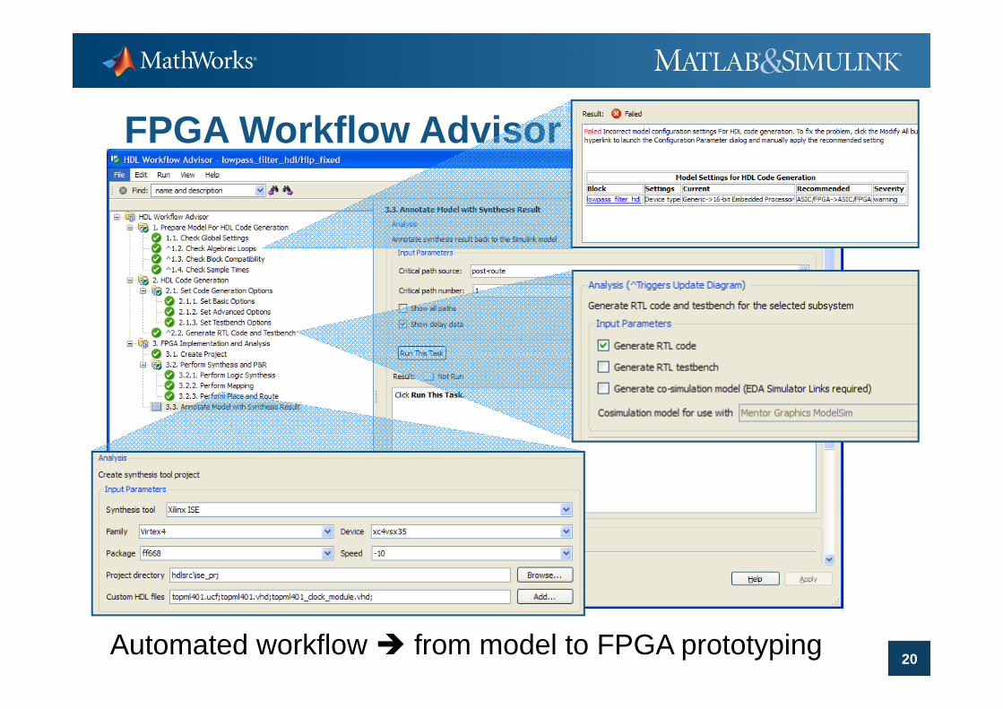
FPGA Workflow Advisor
20Automated workflow from model to FPGA prototyping
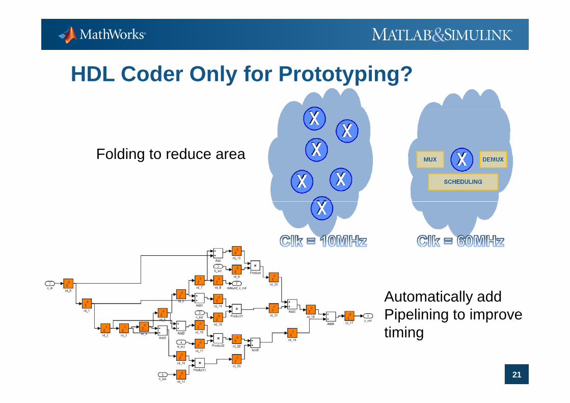
HDL Coder Only for Prototyping?
Folding to reduce areaFolding to reduce area
A t ti ll ddAutomatically add Pipelining to improvetiming
21
g

Summary
Automation of manual steps in FPGA prototyping allowing shorter iteration cyclesg y Assisted Fixed Point Conversion Automatic HDL Code Generation FPGA Turnkey Flow
Integration of FPGA development tools enhances verification Improved analysis, closed loop verification, multi domain
Automatic HDL Code generation can be adapted to meet your requirements
22
Optimization for area and speed

Next steps …..
Visit www.mathworks.nl/fpga for more information
Request a free ‘guided’ Simulink HDL Coder trialq g– Contact your local sales rep
Watch our Simulink HDL Coder webinars:Watch our Simulink HDL Coder webinars:– http://www.mathworks.nl/company/events/webinars
23Questions??


