Aluminum Structure Color Skinz™ Snap On Structure Wrap Available With Star Foam Wash Material Less Than 7 Feet of Tunnel Space required 10 Feet Overall Height Cleans Up to 150 Cars per Hour Line Speed Built-In Foam Streamer™ for added Show and Proper Lubrication
Suggested Installation Tools and Materials
Hammer Drill with 1/2” Drill Bit (12) Wedge Anchor Bolts 1/2” x 5-1/2” Sledge Hammer Safety Goggles Set of Standard Combo Wrenches Torpedo Level Measuring Tape 3/8” Polyflow Tubing 1/2" Polyflow Tubing
Notes and safety Symbols Where necessary, important points will be highlighted in this manual, using the following symbols:
NOTE: PROVIDES FURTHER INFORMATION!
WARNING! DANGEROUS SITUATION WHICH MAY CAUSE EQUIPMENT DAMAGE, PERSONAL INJURIES OR FATALITIES!
Always follow all “Notes”, “Warnings” and instructions. Failure to do so may have serious consequences on the overall performance of the equipment and/or the safety of the people working on the equipment!
Installation Procedures
Upon receiving your MCWW equipment, open all boxes and crates and verify that you have all the required components and that there is no damage to the equipment. Also verify that you have all your installation materials.
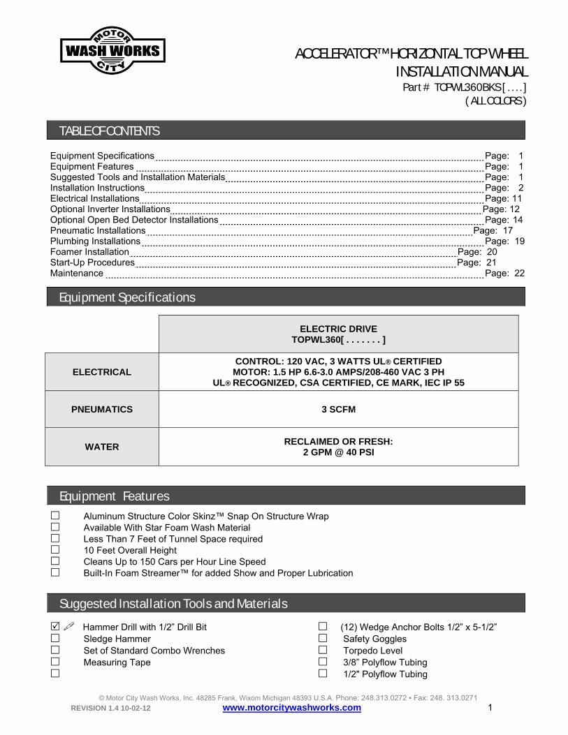
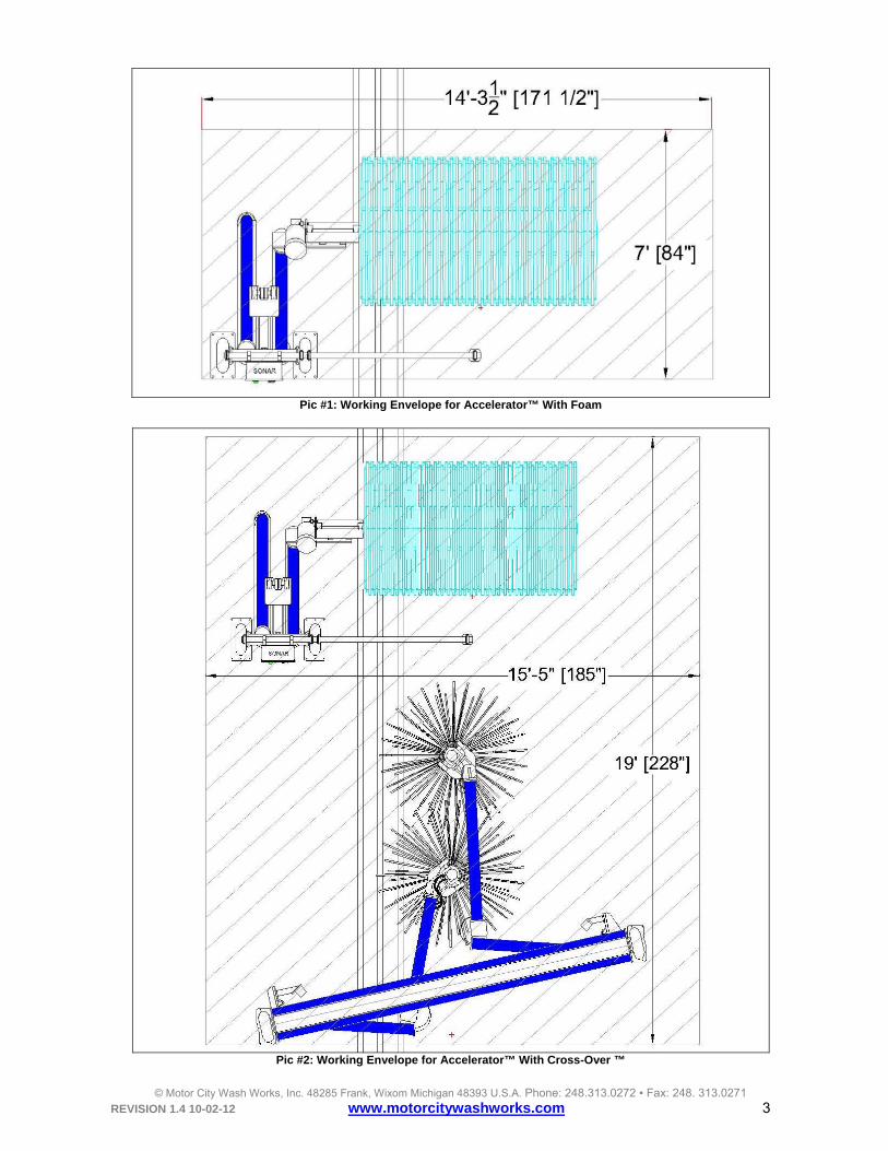
Remove packaging material covering your ACCELERATOR™ TOP WHEEL and bring it to the wash in the area where it will be installed and verify that the area is sufficiently large for the ACCELERATOR™ TOP WHEEL WORKING ENVELOPE and DIMENSIONS (see Picture #1 though #4).
STOP! PRECAUTION TO TAKE TO AVOID EQUIPMENT MALFUNCTION OR ERROR!
PLEASE COMMUNICATE WITH YOUR LOCAL MOTOR CITY WASH WORKS REPRESENTATIVE FOR ANY DAMAGE TO YOUR EQUIPMENT!
Pic #4: Accelerator™ and Cross-Over™ Overall Dimensions
FOR DRIVER SIDE TOP WHEEL:
Position the frame on the DRIVER SIDE OF THE CONVEYOR with the two arms pointing toward the exit. Position the inside edge of the inside leg 21 INCHES to the OUTSIDE EDGE OF THE OUTSIDE GUIDE RAIL (see Picture #5).
FOR PASSENGER SIDE TOP WHEEL: Position the frame on the PASSENGER SIDE OF THE WASH BAY with the two arms pointing toward the exit. Position the inside edge of the inside leg 112 INCHES to the OUTSIDE EDGE OF THE OUTSIDE GUIDE RAIL (see Picture #6).
1'-9" [21"]
9'-4" [112"]
Pic #5: D/S Distance to Outside Guide Rail Pic #6: p/S Distance to Outside Guide Rail
Pic #7: Level Frame (1) Pic #8: Level Frame (2)
Level the frame in both directions (see Picture #7 and #8). Secure to the floor using 1/2” x 5” ANCHOR BOLTS (one for each floor mount holes).
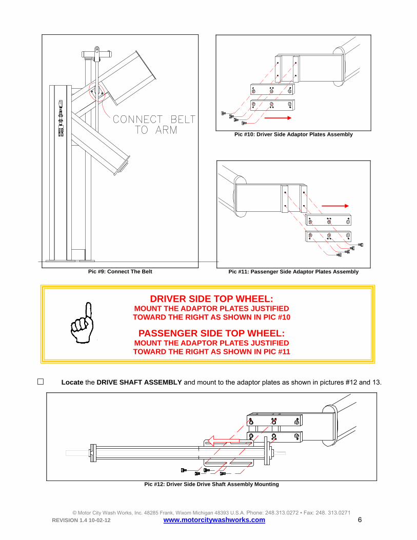
Attach the belt to the arm (see Picture #9)
Locate the ADAPTOR PLATES and secure it on the arm as shown in picture #10 or 11.
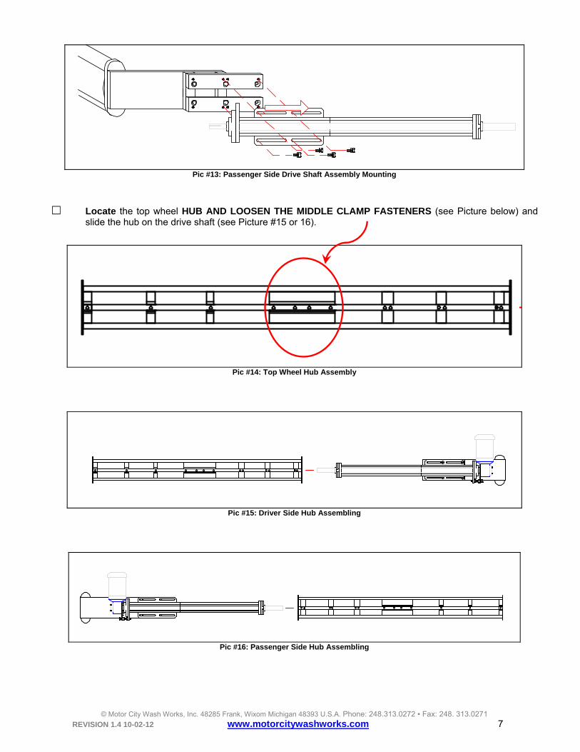
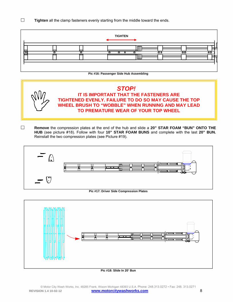
Tighten all the clamp fasteners evenly starting from the middle toward the ends.
Pic #16: Passenger Side Hub Assembling
Remove the compression plates at the end of the hub and slide a 20” STAR FOAM “BUN” ONTO THE HUB (see picture #18). Follow with four 10” STAR FOAM BUNS and complete with the last 20” BUN. Reinstall the two compression plates (see Picture #19).
Pic #17: Driver Side Compression Plates
Pic #18: Slide In 20’ Bun
TIGHTEN
STOP! IT IS IMPORTANT THAT THE FASTENERS ARE
TIGHTENED EVENLY. FAILURE TO DO SO MAY CAUSE THE TOP WHEEL BRUSH TO “WOBBLE” WHEN RUNNING AND MAY LEAD
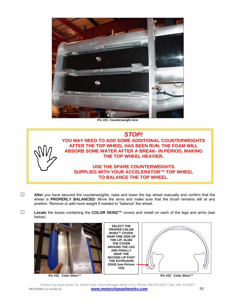
Raise the Top Wheel arm with a FORK LIFT TRUCK or a GENIE LIFT™ to its highest position, the COUNTERWEIGHT ARM should now be at its lowest position. Your top wheel comes with 8 x 1” COUNTERWEIGHT and 4 x 1/4" COUNTERWEIGHTS. Add all the 1” counterweight (4 IN THE TOP SLOT AND 4 IN THE BOTTOM SLOT) and 2 x 1/4" counterweight in the TOP or BOTTOM slot to the counterweight arm box (see picture #20 and 21). Keep the remaining counterweight for future usage.
Pic #20: Counterweights
NOTE: YOU MAY LEAVE THE TOP WHEEL BRUSH DOWN AND LOAD
THE COUNTERWEIGHTS, ONE-AT-A-TIME USING A STEP LADDER
After you have secured the counterweights, raise and lower the top wheel manually and confirm that the
wheel is PROPERLY BALANCED: Move the arms and make sure that the brush remains still at any position. Remove or add more weight if needed to “balance” the wheel.
Locate the boxes containing the COLOR SKINZ™ covers and install on each of the legs and arms (see
below).
Pic #22 Color Skinz™ Pic #23 Color Skinz™
STOP! YOU MAY NEED TO ADD SOME ADDITIONAL COUNTERWEIGHTS
AFTER THE TOP WHEEL HAS BEEN RUN. THE FOAM WILL ABSORB SOME WATER AFTER A BREAK- IN PERIOD, MAKING
THE TOP WHEEL HEAVIER.
USE THE SPARE COUNTERWEIGHTS SUPPLIED WITH YOUR ACCELERATOR™ TOP WHEEL
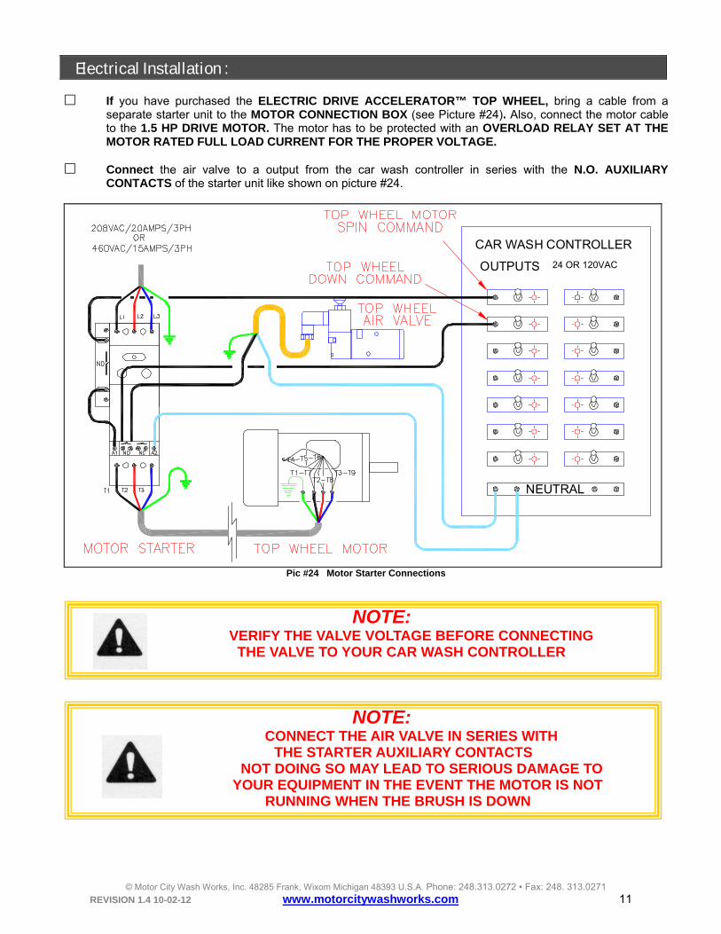
If you have purchased the ELECTRIC DRIVE ACCELERATOR™ TOP WHEEL, bring a cable from a separate starter unit to the MOTOR CONNECTION BOX (see Picture #24). Also, connect the motor cable to the 1.5 HP DRIVE MOTOR. The motor has to be protected with an OVERLOAD RELAY SET AT THE MOTOR RATED FULL LOAD CURRENT FOR THE PROPER VOLTAGE.
Connect the air valve to a output from the car wash controller in series with the N.O. AUXILIARY CONTACTS of the starter unit like shown on picture #24.
OUTPUTS 120VAC ONLY
CAR WASH CONTROLLER
NEUTRAL
Pic #24 Motor Starter Connections
NOTE: VERIFY THE VALVE VOLTAGE BEFORE CONNECTING
THE VALVE TO YOUR CAR WASH CONTROLLER
NOTE: CONNECT THE AIR VALVE IN SERIES WITH
THE STARTER AUXILIARY CONTACTS NOT DOING SO MAY LEAD TO SERIOUS DAMAGE TO YOUR EQUIPMENT IN THE EVENT THE MOTOR IS NOT
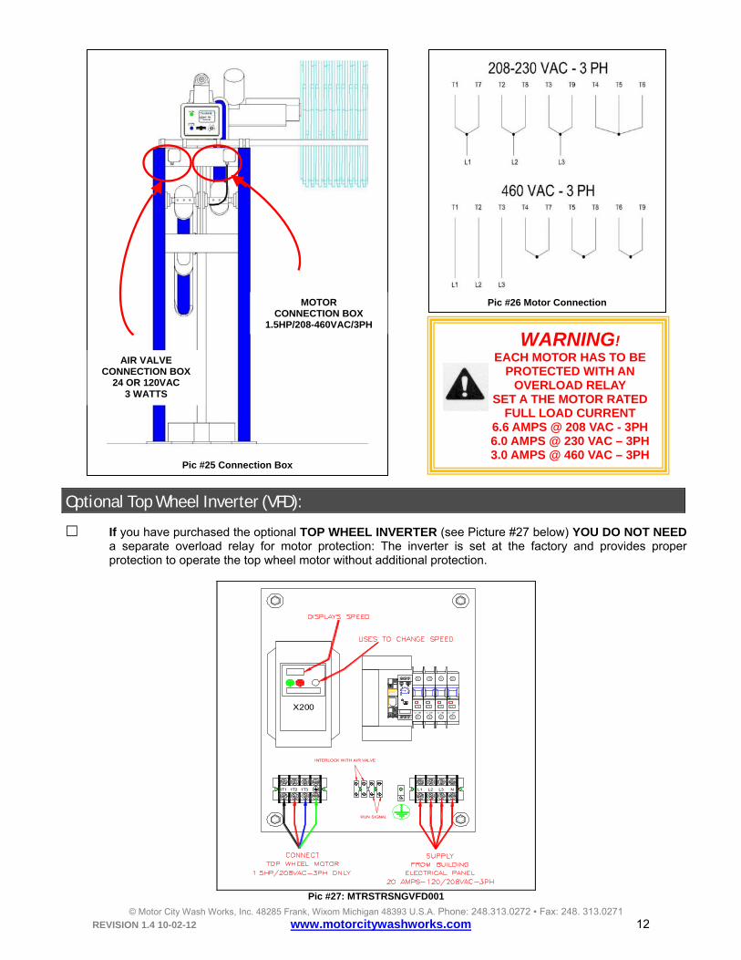
If you have purchased the optional TOP WHEEL INVERTER (see Picture #27 below) YOU DO NOT NEED a separate overload relay for motor protection: The inverter is set at the factory and provides proper protection to operate the top wheel motor without additional protection.
Secure the sonar mount on top of the frame (see Picture #29) using the green clamps and then mount the DETECTOR CONTROL BOX on the brackets provided with your system.
Open-BedDetector
Accelerator
DETECTEDOPEN BED
POWER
Pic #29: Open Bed Detector
Your detector comes with four electrical cables connected to the box (see Picture below):
• A GREY POWER CORD: To be connected to a SEPARATE 120VAC- 15AMPS power source.
• A (SHORT) GREY AIR VALVE CABLE: To be connected IN SERIES with the air valve solenoid.
• A BLACK CABLE: For the sonar sensor. • AND FINALLY A BLACK CONTROL CABLE: Connected to the car wash
Connect the power cable to a 120VAC-15AMPS SEPARATE ELECTRICAL CIRCUIT.
Connect the AIR VALVE CABLE to the air solenoid valve leads inside the AIR VALVE JUNCTION BOX (see Picture #31).
OUTPUTS 120VAC ONLY
CAR WASH CONTROLLER
NEUTRAL
Pic #31: Air Valve Junction Box
Pull the SONAR CABLE through the sonar mount and connect the end of the cable (terminated with a M12 Micro DC connector) to the sonar sensor (see Picture 32).
Finally, the control cable is currently provided with FOUR PAIR OF WIRES (see Picture #33):
• Connect the READY SIGNAL WIRES (pair #1) to ONE FUNCTION OF THE CAR WASH CONTROLLER. This signal is used to turn ON the detection process when a car is present under the sonar. The function has to be programmed to turn ON with the front of the vehicle and turn OFF with the rear of the vehicle.
• You may also want to connect the WATER CONTROL WIRES (pair #2) in series with the foamer dilution station. Your OPEN BED DETECTOR will then turn OFF the foamer every time a truck with an open bed is being detected.
• You may also use the OPEN BED DETECTED wires (wire pair #3) to send an input signal
to your car wash controller if needed. The detector will close a set of contacts which are internally connected to the “DETECTED” pair of wires every time a truck with an open bed is detected.
Pic #33: Control Cable
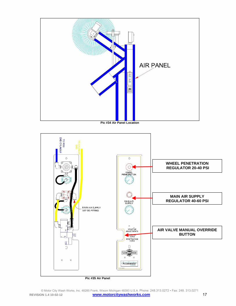
Pneumatic Installation:
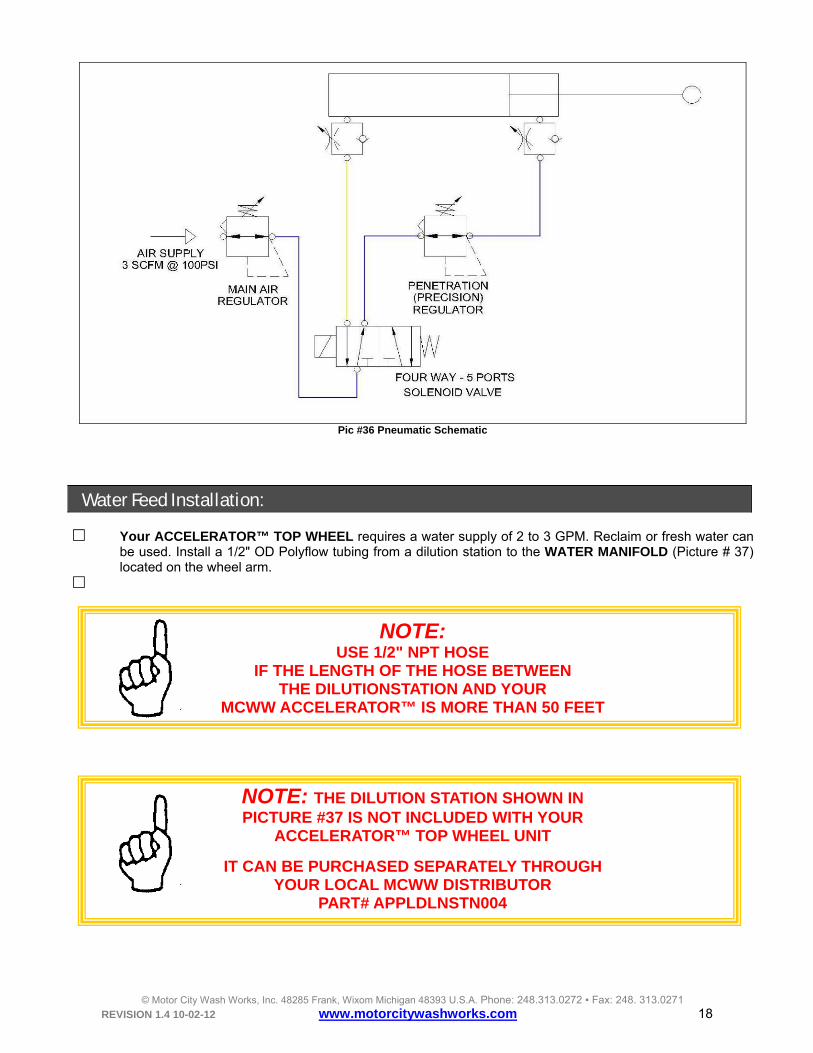
Your MCWW ACCELERATOR™ TOP WHEEL requires a supply of compressed air capable of 3 SCFM @ 100 PSI.
WARNING! IT IS IMPERATIVE TO SUPPLY THE ACCELERATOR™ PNEUMATIC
SYSTEM WITH “CLEAN DRY COMPRESSED AIR”
ANY AMOUNT OF MOISTURE, VAPORIZED OIL OR ANY OTHER IMPURITIES WITHIN THE MAIN AIR SUPPLY MAY
AFFECT THE PERFORMANCE OF THE EQUIPMENT AND LEAD TO PREMATURE WEAR OR MAJOR DAMAGE
TO THE ACCELERATOR™ DELIVERY SYSTEM OR ITS COMPONENTS
Bring a 3/8” OD polyflow tubing air line from the main compressed air supply to the AIR PANEL MAIN AIR SUPPLY FITTING (see Picture # 35).
Your ACCELERATOR™ TOP WHEEL requires a water supply of 2 to 3 GPM. Reclaim or fresh water can be used. Install a 1/2" OD Polyflow tubing from a dilution station to the WATER MANIFOLD (Picture # 37) located on the wheel arm.
NOTE: USE 1/2" NPT HOSE
IF THE LENGTH OF THE HOSE BETWEEN THE DILUTIONSTATION AND YOUR
MCWW ACCELERATOR™ IS MORE THAN 50 FEET
NOTE: THE DILUTION STATION SHOWN IN PICTURE #37 IS NOT INCLUDED WITH YOUR
ACCELERATOR™ TOP WHEEL UNIT
IT CAN BE PURCHASED SEPARATELY THROUGH YOUR LOCAL MCWW DISTRIBUTOR
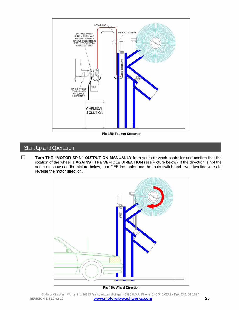
Turn THE “MOTOR SPIN” OUTPUT ON MANUALLY from your car wash controller and confirm that the rotation of the wheel is AGAINST THE VEHICLE DIRECTION (see Picture below). If the direction is not the same as shown on the picture below, turn OFF the motor and the main switch and swap two line wires to reverse the motor direction.
NOTE: IF YOUR ACCELERATOR™ TOP WHEEL MOTOR IS DRIVEN BY A STARTER, THE WHEEL SPEED IS PRESET AT 88 RPM IF YOU ARE USING THE TOP WHEEL INVERTER, YOU MAY ADJUST THE SPEED OF THE WHEEL FROM 88 RPM TO 120 RPM BY TURNING THE INVERTER ADJUSTMENT KNOB TO THE DESIRED SPEED. THE INVERTER SCREEN DISPLAYS THE ACTUAL WHEEL SPEED
(SEE PREVIOUS PICTURE #27)
With the wheel still spinning, turn ON the “TOP WHEEL DOWN” OUTPUT FUNCTION from your car wash controller and confirm the wheel is coming down. If the wheel is not coming down or takes too long to come down, verify that the FLOW CONTROL BANJO FITTING AT THE BASE OF THE CYLINDER is fully open or at least OPEN BY 5 FULL TURNS (COUNTER CLOCKWISE). You may also increase the PENETRATION AIR PRESSURE from 20 PSI to 30 PSI or 40 PSI.
While the wheel is still spinning, turn OFF the “SPIN” OUTPUT FUNCTION and confirm that the top wheel
completely retracts up, away from the vehicle. Turn OFF the “TOP WHEEL DOWN” OUTPUT FUNCTION.
Manually turn ON the WATER DILUTION STATION and confirm that the SPRAY NOZZLES COVERS the wheel. Turn OFF your dilution station. Consult your MCWW Dilution Station Installation manual for adjustment.
Run a car through the wash and verify proper operation of your MCWW ACCELERATOR TOP WHEEL.
Increase or decrease the “PENETRATION” air regulator for increase or decrease of wheel penetration on the car.
While the wheel is down on a vehicle, measure with a clamp amp-meter the current through the motor. The current should never reach a value higher than 6.6 amps.
Maintenance: DAILY:
• Check for hydraulic leaks, chaffed hoses electrical cable, etc.
• Visually inspect for any sign of wear.
• Move the arms manually and duplicate its regular motion and look for abnormalities: A loose fastener may
allow some parts to move or rub and may create a dark “stain” running down the equipment.
• Inspect belts for wear and/cuts or cracks and replace as needed.
• WARNING! IMMEDIATELY REPLACE A BELT SHOWING ANY
ABNORMALITY LIKE WEAR MARKS, CRACKS, RUST OR CUTS AS IT MAY HAVE BEEN CAUSED BY A MISADJUSTMENT OF THE
SAFETY BELT (DOUBLE BELT) OR BY CHEMICALS USED IN YOUR WASH PROCESS WHICH WILL AFFECT THE INTEGRITY
• Start the day with a “TEST WASH” and check for proper operation.
• While you are watching the TEST WASH, check for clogged nozzles. If a nozzle is clogged, remove the
nozzle body and clean the nozzle by inserting a small piece of wire (a small paper clip wire will be fine!) in
the nozzle opening.
• Check also for proper coverage of the Streamer™ Foamer.
• Check for the overall performance of the equipment on the vehicle: Profiling, cleaning, etc..
• Wash down your equipment and the area around at the end of each day. MONTHLY: Each piece of MCWW equipment is assembled with the highest quality bearings and have been factory pre-
lubricated, therefore, they do not require supplemental grease for the first month of operation.
Use a lithium-based NLGI #2 grease (ex: Exxon Mobil MOBILITH AW2).
WARNING! OVERLUBRICATION IS A MAJOR CAUSE OF BEARING FAILURES!
LUBRICATE CONSERVATIVELY!
• After the first month of operation, grease each bearing (see Picture #40 and 41).
• Wash your equipment with a solution made of a mild degreaser and water. Rinse thoroughly.
• Perform daily maintenance.
Pic #40 Top Wheel Axle Bearing Pic #41 Top Wheel Arms Bearings
Warranty and Return Procedure: Motor City Wash Works warrants this product to be free of defect in material and/or workmanship for a period of one year from the date of purchase. During the warranty period MCWW will at its discretion, at no charge to the customer, repair or replace this product if found defective, with a new or refurbished unit, but not to include costs of removal or installation. Any product returned to MCWW for warranty has to have a Return Material Authorization Number. All shipping costs to MCWW are assumed by the customer. This is only a summary of the MCWW Limited Warranty. Please, communicate with MCWW for our complete warranty. Prior to returning any product to MCWW, the customer must call in for a Return Material Authorization Number and a copy of our Return Material Authorization Form must be completed. The RMA number must be written clearly on the outside of the shipping package and a copy of the form must be included in the package.