FPZ S.p.A. Via F.lli Cervi 16, 20863 Concorezzo (MB), ITALY Tel. +39 039.69.09.81 [email protected]www.fpz.com ACCESSORIES FOR BLOWERS DSA_EU_EN_16_04 ACCESSORIES FOR SIDE CHANNEL BLOWERS - EXHAUSTERS - Technical data
Transcript
FPZ S . p . A . V i a F . l l i Cerv i 16 , 20863 Concorezzo (MB) , I TALY Tel . +39 039. 69. 09. 81 i n fo@fpz . com w w w . fpz . com
ACCESSORIES FOR BLOWERS DSA_EU_EN_16_04
ACC
ESSO
RIES
FO
R S
IDE
CH
AN
NEL
BLO
WER
S -
EXH
AU
STER
S
- T
echn
ical
dat
a
ACCESSORIES FOR BLOWERS
Sizes in [mm] - NOT BINDING DSA_EU_EN_16_04 page 2
Model DESCRIPTION NOTES
CA MANIFOLD CA for FA /FL filters Use only in suction, for installing directly on the silencer housing oriented horizontally.
CF CARTRIDGE CF Spare for filter FL.
CK MANIFOLD FOR K series blowers For installing the silencer housing vertically on the cover. In this case the blind flange will be installed on the body.
CL CARTRIDGE CL Spare for filter FC.
CV CARTRIDGE CV Spare for filter FV.
FA SUCTION FILTER FOR INTERIORS Direct fitting to the blower is possible via SECTION TR on the threaded flange or via MANIFOLD CA for filters.
FC IN LINE CARTRIDGE CYCLONE FILTER Sleeves with GAS external thread.
FL SUCTION CARTRIDGE FILTER Direct fitting to the blower is possible via SECTION TR on the threaded flange or via MANIFOLD CA for filters.
FM FLEXIBLE SLEEVE It makes connection of the blower to the plant flexible and use with HOSE SLEEVE MP and PK is foreseen.
FS BRACKET Filter FC accessory for rigid fixing.
FV IN LINE CARTRIDGE FILTER Sleeves with GAS internal thread.
IH SOUNDPROOF CABIN On models IH1, IH3, IH4 and IH5 fixing of the blower and connection via internal kit included is foreseen. Fixing of cabins to the floor is not foreseen. The remaining models have an open bottom and are arranged for fixing to the floor.
IP PROTECTION IN SUCTION Also suitable for protecting the inlet of RELIEF VALVE VRL.
MC PRESSURE GAUGE For reading the pressure at the discharge. It is installed directly on VALVE HOLDER PV and via adapter (G1/4" - G1/8") on the silencer housing.
MP HOSE SLEEVE It replaces THREADED FLANGE TF for use of flexible sleeve FM.
MV VACUUM GAUGE For reading the inlet pressure. It is installed directly on VALVE HOLDER PV and via adapter (G1/4" - G1/8") on the silencer housing.
PK HOSE SLEEVE For using FLEXIBLE SLEEVE FM without the silencer housing.
PV VALVE HOLDER PV For using RELIEF VALVE VRL and for fitting to the blower via THREADED FLANGE TF (GAS) or via FLEXIBLE SLEEVE FM.
RV VACUUM BREAKER VALVE For installing on a derivation of the plant to limit the pressure at the blower inlet.
SI IN LINE SUPPLEMENTARY SILENCER For installing directly on THREADED FLANGE TF (GAS) with atmospheric pressure.
SS FINAL SUPPLEMENTARY SILENCER For installing directly on THREADED FLANGE TF at the discharge with atmospheric pressure.
TF THREADED FLANGE Supplied as standard on all blowers.
TR SECTION FILTER FA and FL accessory (spare for FILTER FL).
VC NON-RETURN VALVE Supplied separately and for installing on the plant duct.
VLA RELIEF VALVE For installing on a derivation of the plant to limit the pressure at the blower discharge.
VK FLANGE VK For installing RELIEF VALVE VRL replacing the blind flange on the main components of the blower.
VRL RELIEF VALVE For fitting directly to the blower via VALVE HOLDER PV or via FLANGE VK.
For more information and details, see the data sheet of the individual accessories in this document.
ACCESSORIES FOR BLOWERS
Sizes in [mm] - NOT BINDING DSA_EU_EN_16_04 page 3
GENERAL TABLE OF ACCESSORIES for BLOWERS type MS / MD
8 (1) Manifold CA4V is also suitable if installation in soundproof cabin IH is foreseen. (2) Manifold CA5V is also suitable if installation in soundproof cabin IH is foreseen. (3) The use of valve VRL6 is required (4) Necessary if valve VRL6 is used (5) Necessary if valve VRL8 is used (6) Applicable only at the inlet for blowers K-MD (7) It’s necessary to use the reduction 25RID-FM54 (8) Accessory to be installed on the system
ACCESSORIES FOR BLOWERS
Sizes in [mm] - NOT BINDING DSA_EU_EN_16_04 page 4
GENERAL TABLE OF ACCESSORIES for BLOWERS type TS/TD
TS TD
K05-66 K05 K07 K09 K04 K05 K07 K09 K11
K06 K08 K10 K06 K08 K10 K12
K11
K12
ø 2” 3” 4” 5” 1” 1/2 2” 3” 4”
DN 50 80 100 125 40 50 80 100
CA 6V 8 9 10 N.A. N.A. N.A. N.A.
CF 6 8 9 9 5 6 8 9
CK 6 8 9 10 N.A. N.A. N.A. N.A.
CL 6 8 9 - 5 6 8 9
CV 6 6 - 10 5 6 6 -
FA 6 8 9 10 5 6 8 9
FC 6 8 9 - 5 6 8 9
FL 6 8 9 10 5 6 8 9
FM 6 8 9 10 5 6 8 9
FS 6 8 9 - 5 6 8 9
FV 6 8 - 10 5 6 8 -
IH - - 9 13 - - 8 11 12
IP 6 6 (4) 8 (5)
6 (4) 8 (5)
9 9 5
6 (4) 6 6 (4) 8
6 (4) 8 (5) 9
MC 040 040 040 040 040 040 040 050
MP 6 8 9 10 5V 6 8 9
MV 020 020 020 020 020 020 020 020
PK 6 8 (9) 9 (9) 9 5 6 8 9
PV 66 86 (4) 88
96 (4) 98 (5)
99 109 56 66 86 (4)
88 96 (4) 98 (5)
96 (4) 98 (5)
99
RV - - - - - - -
SI 6 8 9 - 5 6 8 9
SS 6 8 9 - 5 6 8 9
TF 6 8 9 10 5V 6 8 9
TR 6 8 9 10 5 6 8 9
VC 6 8 9 10 5 6 8 9
VLA - - - - - - - -
VK 6 6 8 (9)
6A (4) 8 (5) 9 (9)
9 N.A. N.A. N.A. N.A.
VRL 6 6 8
6 8 9
9 6 6 6
6HP 8
6 6HP
8
6 8 9
(4) Necessary if valve VRL6 is used (5) Necessary if valve VRL8 is used (9) It’s also necessary to use the TS manifold
ACCESSORIES FOR BLOWERS
Sizes in [mm] - NOT BINDING DSA_EU_EN_16_04 page 5
SUCTION FILTER FOR INTERIORS - FA Standard version: filter element in paper.
- Filter complete with connector clamp. Available on request:
- section in PVC, Model “TR4 ÷TR10” - other filter elements with different degrees of filtration (see table below) - Manifold with wide-radius curve “CA” type for use of filter vertically (applicable for MOR/GOR blowers)
DIMENSIONS * (FA)
(*) – Standard version filter dimensions and characteristic data
IN LINE CARTRIDGE FILTER - FV Standard version: filter element in paper.
- Container in painted steel with GAS threaded sleeves. Available on request:
- other filter elements with different degrees of filtration (see table below) DIMENSIONS * (FV)
(*) – Standard version filter/cartridge dimensions and characteristic data
FIL
TER
Model DN A B øC øDi FLOW RATE [m3/h]
Weight [kg]
FA 4 32 126 23 126 43 100 0.63 FA 5 40 217 23 152 48.5 300 1.04 FA 6 50 217 23 152 61.5 400 1.00 FA 8 80 150 34 200 89.5 700 1.38 FA 9 100 160 38 257 115.5 1400 2.27 FA 10 125 160 38 257 141 2800 2.20
Filter Element Material Degree of Filtration - Nominal [µm]
Filter Element Material Degree of Filtration - Nominal [µm]
Paper 25 Polyester 10
Stainless steel 60
M
M
Gi A
Gi
Ge
Ge
øB
C
E
ACCESSORIES FOR BLOWERS
Sizes in [mm] - NOT BINDING DSA_EU_EN_16_04 page 6
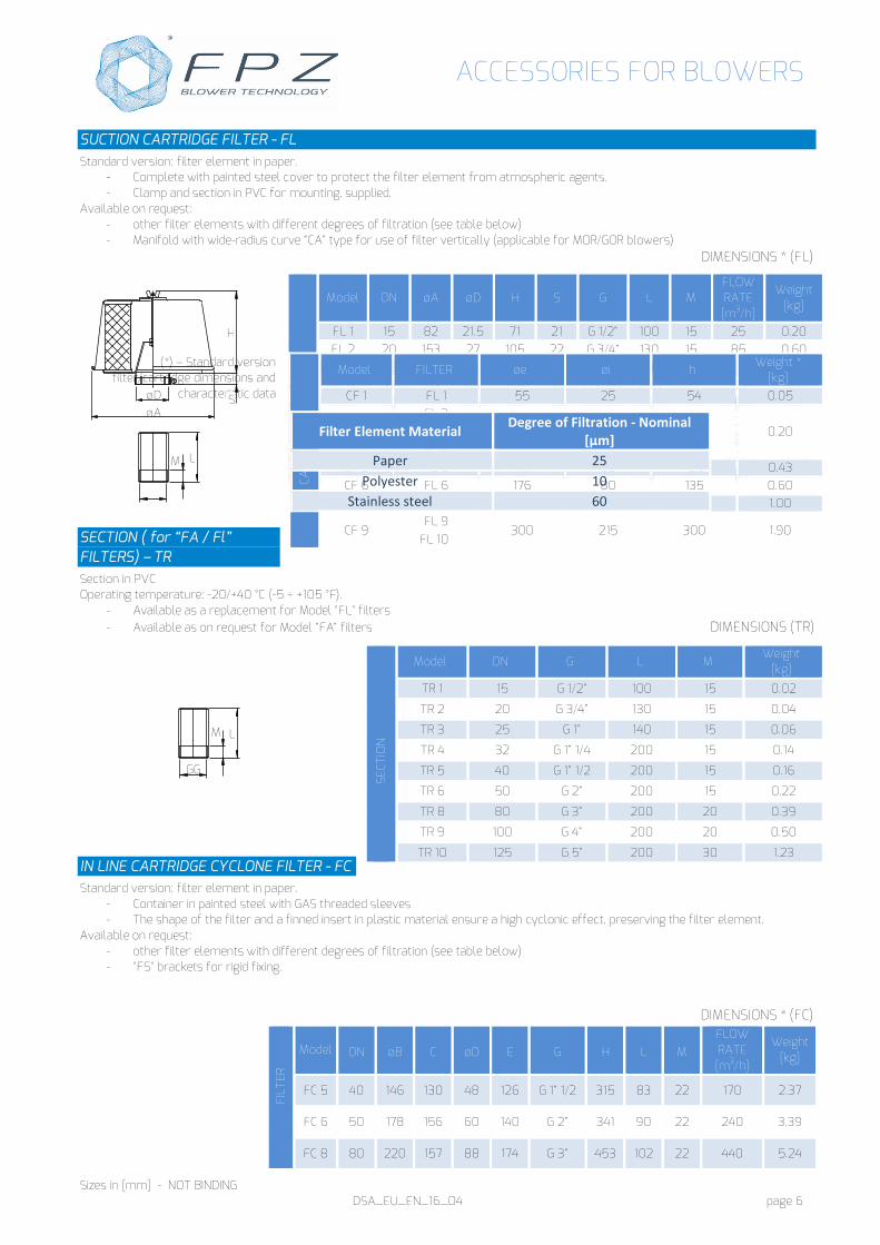
SUCTION CARTRIDGE FILTER - FL Standard version: filter element in paper.
- Complete with painted steel cover to protect the filter element from atmospheric agents. - Clamp and section in PVC for mounting, supplied.
Available on request: - other filter elements with different degrees of filtration (see table below) - Manifold with wide-radius curve “CA” type for use of filter vertically (applicable for MOR/GOR blowers)
DIMENSIONS * (FL)
(*) – Standard version filter/cartridge dimensions and
characteristic data
SECTION ( for “FA / Fl” FILTERS) – TR Section in PVC Operating temperature: -20/+40 °C (-5 ÷ +105 °F).
- Available as a replacement for Model "FL" filters - Available as on request for Model “FA” filters DIMENSIONS (TR)
IN LINE CARTRIDGE CYCLONE FILTER - FC
Standard version: filter element in paper. - Container in painted steel with GAS threaded sleeves - The shape of the filter and a finned insert in plastic material ensure a high cyclonic effect, preserving the filter element.
Available on request: - other filter elements with different degrees of filtration (see table below) - "FS" brackets for rigid fixing.
Filter Element Material Degree of Filtration - Nominal [µm]
Paper 25 Polyester 10
Stainless steel 60
SECT
ION
Model DN G L M Weight
[kg]
TR 1 15 G 1/2” 100 15 0.02
TR 2 20 G 3/4” 130 15 0.04
TR 3 25 G 1” 140 15 0.06
TR 4 32 G 1” 1/4 200 15 0.14
TR 5 40 G 1” 1/2 200 15 0.16
TR 6 50 G 2” 200 15 0.22
TR 8 80 G 3” 200 20 0.39
TR 9 100 G 4” 200 20 0.50
TR 10 125 G 5” 200 30 1.23
FIL
TER
Model DN øB C øD E G H L M FLOW RATE [m3/h]
Weight [kg]
FC 5 40 146 130 48 126 G 1” 1/2 315 83 22 170 2.37
FC 6 50 178 156 60 140 G 2” 341 90 22 240 3.39
FC 8 80 220 157 88 174 G 3” 453 102 22 440 5.24
øA øD S
H
L M
LM
GG
ACCESSORIES FOR BLOWERS
Sizes in [mm] - NOT BINDING DSA_EU_EN_16_04 page 7
(*) – Standard version filter/cartridge dimensions and characteristic data BRACKET ( for filter “FC” ) – FS Galvanised metal bracket for rigid fixing
- Available on request
DIMENSIONS (FS)
MANIFOLD - CA ( for "FA /FL” filters ) 90° manifold in PVC with wide-radius curve, flanged end for fixing to the blower and smooth terminal for filter. Operating temperature: -20/+40 °C (-5 ÷ +105 °F).
DIMENSIONS (CA)
FC 9 100 276 225 114 204 G 4” 493 123 22 730 9.14
C
ART
RID
GE
Model FILTER øe h Weight *
[kg]
CL 5 FC 5 104 264 0.51
CL 6 FC 6 134 290 0.93
CL 8 FC 8 155 395 1.50
CL 9 FC 9 202 421 2.11
Filter Element Material Degree of Filtration - Nominal [µm]
Paper 25 Polyester 10
Stainless steel 60
BR
ACK
ET
Model FILTER R S øT U
FS 5 FC 5 70 84 9 22
FS 6 FC 6 103 93 9 22
FS 8 FC 8 122 112 9 25
FS 9 FC 9 147 126 11.5 32
Model DN A B øD I M R S γ Fig. Weight
[kg]
CA 4 32 220 90 42 75 7 80 15 30° 1 0.22
CA 4V 32 220 90 42 64 7 80 15 - 2 0.22
U øT
R
S
M
G C
øB
H
L
M
E
G
øD
FS
ACCESSORIES FOR BLOWERS
Sizes in [mm] - NOT BINDING DSA_EU_EN_16_04 page 8
PRESSURE GAUGE/VACUUM GAUGE – MC / MV Pressure gauge built according to UNI EN 837.1 - BLACK painted metal case - IP55 - Cylindrical radial connection (ISO 228) - Dial in aluminium, white background Operating values: Operating temperature -10°C to + 60°C Overpressure: 25% (according to EN837.1)
DIMENSIONS (MC/MV)
CA 4K 32 260 160 42 64 7 80 15 - 2 0.32
CA 5 40 260 110 48 85 7 100 15 45° 1 0.43
CA 5V 40 260 110 48 75 7 100 15 - 2 0.43
CA 5K 40 300 180 48 75 7 100 15 - 2 0.55
CA 6 50 320 135 60 85 7 126 15 45° 1 0.73
CA 6V 50 320 135 60 85 7 126 15 - 2 0.73
CA 8 80 380 185 88.5 120 7 180 15 - 3 1.60
CA 9 100 400 235 113.9 150 9 220 20 - 3 3.14
CA 10 125 450 300 140 210 18 280 20 - 3 5.88
Model ∆p
mbar ACCURACY DN B C E G M
Weight [g]
MC 040 0 ÷ 600 1.6% 63 27 10 54 G 1/4” 13 99 MC 050 0 ÷ 1000 1.6% 63 27 10 54 G 1/4” 13 99 MV 020 -600 ÷ 0 1.6% 63 27 10 54 G 1/4” 13 99
øD B
A
S
R
Fig. 2 I M
Fig. 3
M
I
Fig. 1
I
γ
M
E
G
B
DN
C M
ACCESSORIES FOR BLOWERS
Sizes in [mm] - NOT BINDING DSA_EU_EN_16_04 page 9
G
øA M
H
FLEXIBLE SLEEVE Features: - Extremely flexible - Smooth internally - Resists twisting - Good chemical resistance - Steel spring solidly embedded in the fabrics Structure: - Tube wall: neoprene-coated double fibreglass fabric - Spiral: steel wire spring - Reinforcement: double hollow in fibreglass Supplied with pair of clamps. Operating temperature (continuous): -35 ÷ +135 °C (-31 ÷ +275 °F).
DIMENSIONS (FM) Model DN D L FM 1 15 222222 200200 FM 2 20 30 200
FM 3 25 32 200 FM 4 32 45 200
FM 4C 32 45 110 FM 5 40 51 250
FM 5C 40 51 130 FM 6 50 64 250
FM 6C 50 64 135 FM 8 80 90 330
FM 9 100 114 330 FM 10 125 140 330
CHARACTERISTIC DATA (FM)
Model min. radius
of curvature [mm]
max. pressure
[bar]
max. negative pressure [mbar]
Weight
[g] FM 1 15 2.8 650 60 FM 2 15 2.8 650 65 FM 3 16 2.6 650 90 FM 4 21 2.6 560 135
FM 4C 21 2.6 560 85 FM 5 24 2.6 520 180
FM 5C 24 2.6 520 100 FM 6 31 2.4 480 200
FM 6C 31 2.4 480 120 FM 8 44 2.0 400 250 FM 9 57 1.6 290 370 FM 10 70 1.3 190 400
PROTECTION IN SUCTION - IP Filter for check and foot valves. Stainless steel mesh and polymer threaded sleeve. Available with NPT thread only for sizes DN80 and DN100.
DIMENSIONS (IP)
Model DN øA G H M Degree of filtration
Weight [g]
IP4 32 50 G 1” 1/4 75 10 1200 µm 38
IP5 40 56 G 1” 1/2 83 11 1200 µm 47
IP6 50 69 G 2” 98 13 1200 µm 70 IP8 80 102 G 3” 138 15 2000 µm 194
Sizes in [mm] - NOT BINDING DSA_EU_EN_16_04 page 10
H
R
øD L
I
øD
G
L H
H
L øD
I R
M
H S G
I R
Fig.1 Fig.2 Fig.3 Fig.4
HOSE SLEEVE - MP Flange with hose collar in aluminium alloy or steel. Its use replaces the threaded flange on the silencer housing. (the only exception is the sleeve as in fig.4). Sleeves MP 1, MP 2, MP 9 are installed on the respective threaded flange.
MP 10 G 125 - G 5” 60 210 - 30 17 8 3 2.80 MP 10 N 125 - 5” NPT 60 210 - 30 17 8 3 2.80
HOSE FLANGE FOR BLOWER K - PK Flange in aluminium alloy with hose collar, also available painted RAL 7016. Supplied with mounting kit (gasket and screws plus wrench). Allows the connection of K series blowers to the system, without the use of the silencer housing as specified below: • blower K-MS/TS/TD applicable in delivery and in suction; • blower K-MD applicable only on the cover in suction
Sizes in [mm] - NOT BINDING DSA_EU_EN_16_04 page 11
MANIFOLD - CK 90° manifold in aluminium alloy applicable on "K" series blowers, also available painted RAL 7016. Supplied with mounting kit (gasket and screws plus wrench).
DIMENSIONS (CK)
Model DN A B øC øD E E1 F 4xG 4xG1 I I1 I2 I3 I4 Weight
[kg] CK 4 32 69 84.6 - 38 11.5 7.0 56 M6 7 - 14.5 14.5 70.2 70.2 0.36 CK 5 40 80 100 - 43 11.5 7.0 56 M6 7 - 17.6 17.6 85 85 0.50 CK 6 50 92 118 - 55 13.0 8.5 69 M8 9 - 18.3 23.8 99.4 104 0.70 CK 8 80 - - 145 75 10.5 10.5 110 M8 9 130 - - - - 1.37 CK 9 100 - - 165 90 10.5 10.5 132 M8 9 150 - - - - 1.77 CK 10 125 - - 220 128 10.5 10.5 192 M8 9 190 - - - - 3.82 VALVE HOLDER for valves VRL - PV In AISI 304 stainless steel and painted RAL 7016, end with GAS thread and complete with G1/4” hole for connecting pressure gauge MC or vacuum gauge MV. Installs directly onto the threaded flange of the blower (inlet and outlet). Suitable for use of flexible sleeve MF. Model PV 56 provides for 2 sleeves with Gas tapered male thread (Gc 1” 1/2) on both ends.
DIMENSIONS (PV)
Model DN A B C 2xG G1 G2 M1 M2 S Weight
[kg] PV 56 40 325 95 83 G 1/4” G 1“ 1/2 G 2” 15 21.5 40 1.73 PV 66 50 227 95 35 G 1/4” G 2” G 2” 21.5 21.5 40 0.85 PV 86 80 310 135 55 G 1/4” G 3” G 2” 28.0 21.5 54 1.85 PV 88 80 310 130 55 G 1/4” G 3” G 3” 28.0 28.0 54 1.99 PV 96 100 370 150 65 G 1/4” G 4” G 2” 31.5 21.5 67 2.64 PV 98 100 370 173 65 G 1/4” G 4” G 3” 31.5 28.0 67 3.00 PV 99 100 370 147 65 G 1/4” G 4” G 4” 31.5 31.5 67 2.80 PV 109 125 370 175 65 G 1/4” G 5” G 4” 31.5 31.5 80 4.20
E
øD A
øD A
E1
I4
I2
F
I1
I3
B
I2 I1
4xG CK 4/CK 5/CK 6
øC
E
øC
øD
E1
øD
4xG
I F
CK 8/CK 9/CK 10
4xG1
4xG1
2xG
G2
G1
C
M1
A/2
A
M1
G1
B
S S
ACCESSORIES FOR BLOWERS
Sizes in [mm] - NOT BINDING DSA_EU_EN_16_04 page 12
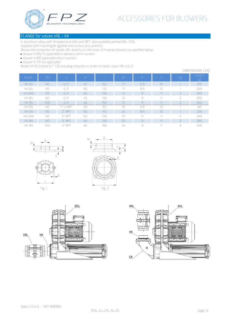
FLANGE for valves VRL - VK In aluminium alloy with threaded end, GAS and NPT, also available painted RAL 7016. Supplied with mounting kit (gasket and screws plus wrench). Allows the connection of valves VRL directly on the cover of K series blowers as specified below: • blower K-MS/TS applicable in delivery and in suction; • blower K-MD applicable only in suction; • blower K-TD not applicable. Model VK 5G (native G 1” 1/2) including reduction in order to install valve VRL 6 G 2"
Sizes in [mm] - NOT BINDING DSA_EU_EN_16_04 page 13
2xR1
S H
G I
4xR2
I
THREADED FLANGE - TF In aluminium alloy and available with female thread, GAS and NPT, also available painted RAL 7016. Supplied standard with blower.
DIMENSIONS (TF)
Model DN G H I 2xR1 4xR2 S Weight
[g] TF 3 G 25 G 1” 18 54.5 6.5 - 10 47
TF 4 G 32 G1“ 1/4 18 75 6.5 - 10 95
TF 4V G 32 G1“ 1/4 18 64 6.5 - 10 50
TF 5 G 40 G1“ 1/2 18 85 6.5 - 10 130
TF 5V G 40 G1“ 1/2 18 75 6.5 - 10 80
TF 6 G 50 G 2“ 18 85 6.5 - 10 100
TF 8 G 80 G 3“ 25 120 - 6.5 13 200
TF 9 G 100 G 4“ 25 150 - 9 13 285
TF 10 G 125 G 5“ 35 210 - 17 13 770
TF 3 N 25 1” NPT 18 54.5 6.5 - 10 47
TF 4 N 32 1“ ¼ NPT 18 75 6.5 - 10 95
TF 4V N 32 1“ ¼ NPT 18 64 6.5 - 10 50
TF 5 N 40 1“ ½ NPT 18 85 6.5 - 10 130
TF 5V N 40 1“ ½ NPT 18 75 6.5 - 10 80
TF 6 N 50 2“ NPT 18 85 6.5 - 10 100
TF 8 N 80 3“ NPT 25 120 - 6.5 13 200
TF 9 N 100 4“ NPT 25 150 - 9 13 285
TF 10 N 125 5“ NPT 35 210 - 17 13 770 NON-RETURN VALVE - VC Valve body and metal parts in brass alloy Shutter gasket: NBR only for Model VC 10 GAS female threaded connections Min./Max. nominal operating pressure : 0.05 bar / 10 bar (6 bar for sizes G 3” and G 4”) Operating temperature: 0°C - +90°C
DIMENSIONS (VC)
Model DN A B G Ch
Hex Weight
[kg] VC 1 15 8 47 G 1/2” 25 0.16 VC 2 20 8 53 G 3/4” 32 0.33 VC 3 25 10 63 G 1” 38 0.38 VC 4 32 10 74 G 1” 1/4 47 0.46 VC 5 40 10 87 G 1” 1/2 55 0.74 VC 6 50 11 97 G 2” 67 1.02 VC 8 80 16 135 G 3” 95 2.44 VC 9 100 20 164 G 4” 124 3.90 VC 10 125 22 206 G 5” 150 6.97
A
B
G G
Ch
ACCESSORIES FOR BLOWERS
Sizes in [mm] - NOT BINDING DSA_EU_EN_16_04 page 14
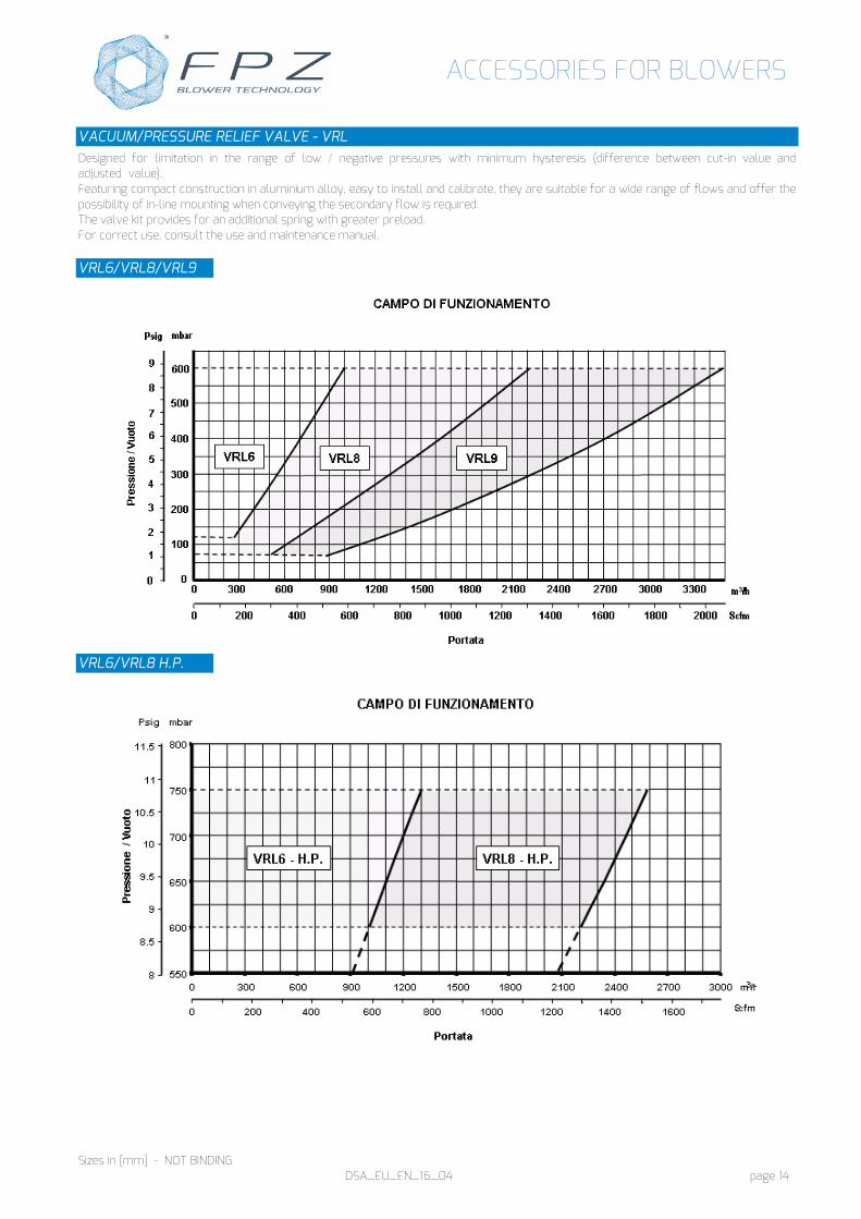
VACUUM/PRESSURE RELIEF VALVE - VRL Designed for limitation in the range of low / negative pressures with minimum hysteresis (difference between cut-in value and adjusted value). Featuring compact construction in aluminium alloy, easy to install and calibrate, they are suitable for a wide range of flows and offer the possibility of in-line mounting when conveying the secondary flow is required. The valve kit provides for an additional spring with greater preload. For correct use, consult the use and maintenance manual. VRL6/VRL8/VRL9
VRL6/VRL8 H.P.
ACCESSORIES FOR BLOWERS
Sizes in [mm] - NOT BINDING DSA_EU_EN_16_04 page 15
DIMENSIONS (VRL)
Flow diagram1 VACUUM/PRESSURE RELIEF VALVE closed VACUUM/PRESSURE RELIEF VALVE open
SUCT
ION
COM
PRES
SIO
N
VACUUM/PRESSURE RELIEF VALVE – RV / VLA Valve body and plate in aluminium alloy. Available with GAS thread only.
DIMENSIONS (VLA/RV)
RV 3 VLA 3 1 Attention : For the correct reading of the value given on the pressure gauge/vacuum gauge, position the instrument between the silencer housing and the VRL
(*) See the relevant data sheet
VA
LVE
Model DN A B G H Weight
[kg]
VRL 6 G 50 102 175 G 2” 12 0.89
VRL 6HP G 50 102 175 G 2” 12 0.89
VRL 8 G 80 135 190 G 3” 15 2.02
VRL 8HP G 80 135 190 G 3” 15 2.02
VRL 9 G 100 160 206 G 4” 18 2.81
VRL 6 N 50 102 175 2” NPT 12 0.89
VRL 6HP N 50 102 175 2” NPT 12 0.89
VRL 8 N 80 135 190 3” NPT 15 2.02
VRL 8HP N 80 135 190 3” NPT 15 2.02
VRL 9 N 100 160 206 4” NPT 18 2.81
Model DN G H Weight
[g]
RV 3 25 G 1” 57 70
VLA 3 25 G 1” 57 70
G
A
B
G
H
H
H H
G G
ACCESSORIES FOR BLOWERS
Sizes in [mm] - NOT BINDING DSA_EU_EN_16_04 page 16
IN LINE SILENCER – SI Suitable for fitting on the inlet pipe as well the outlet pipe under the following conditions: - Inlet installation allowed if the machine works as a blower (suction pressure equal to atmospheric pressure) - Outlet installation allowed if the machine works as an exhauster (discharge pressure equal to atmospheric pressure) In steel sheet (except SI9 and SS9 entirely in aluminium alloy) with polyurethane sound-absorbing element, they reduce the noise of the conveyed flow by absorption. In line silencer SI for in line mounting with GAS threaded sleeve at both ends.
Average indicative attenuation values
DIMENSIONS (SI)
Model DN A2 B øC G L M Weight
[kg] SI 4 32 240 140 70 G 1” 1/4 50 15 0,57 SI 5 40 230 170 80 G 1” 1/2 30 20 0,55 SI 6 50 260 200 90 G 2” 30 20 0,63 SI 8 80 570 400 152 G 3” 85 20 2,95 SI 9 100 485 430 169 G 4” 27 20 3.90
M
B
L
L M
øC G
A2
dB(A) 15
10
5
0
SI 4
dB(A) 20 15 10 5 0
SI 6
dB(A) 15
10
5
0
SI 5
dB(A) 30
20
10
0
SI 8
dB(A) 30
20
10
0 250 500 1k 2k 4k 8k 16k
Hz
SI 9
ACCESSORIES FOR BLOWERS
Sizes in [mm] - NOT BINDING DSA_EU_EN_16_04 page 17
FINAL SILENCER - SS Suitable for fitting on the inlet pipe as well the outlet pipe under the following conditions: - Inlet installation allowed if the machine works as a blower (suction pressure equal to atmospheric pressure) - Outlet installation allowed if the machine works as an exhauster (discharge pressure equal to atmospheric pressure) In steel sheet (except SI9 and SS9 entirely in aluminium alloy) with polyurethane sound-absorbing element, they reduce the noise of the conveyed flow by absorption. Final silencer SS for mounting at head of duct with GAS threaded sleeve to one end and opening to the atmosphere at other end.
Average indicative attenuation values
DIMENSIONS (SS)
Model DN A1 B øC G L M Weight
[kg] SS 4 32 190 140 70 G 1” 1/4 50 15 0,38 SS 5 40 200 170 80 G 1” 1/2 30 20 0,44 SS 6 50 230 200 90 G 2” 30 20 0,50 SS 8 80 485 400 152 G 3” 85 20 2,04 SS 9 100 465 430 169 G 4” 27 20 4,10
dB(A) 20 15 10 5 0
SS 4
dB(A)
20
10
0
SS 5
dB(A) 20 15 10 5 0
SS 6
dB(A) 30
20
10
0
SS 8
dB(A) 30
20
10
0 250 500 1k 2k 4k 8k 16k
Hz
SS 9
B
L M
øC G
A1
ACCESSORIES FOR BLOWERS
Sizes in [mm] - NOT BINDING DSA_EU_EN_16_04 page 18
lined with sound-absorbing material. • Arranged with electric axial fan for removing
heat generated by the motor and blower. • Bottom of cabin with air inlet grille for ventilation. • Cabin on 4 rubber antivibration mounts. • Cabin supplied with kit for connection of blower. • Possibility of installing the accessories provided for the blower
directly on the cabin. • Not suitable for outdoor installation without adequate protection. PERFORMANCE OF BLOWERS (MOR IE2 Wide Range version) INSTALLED IN SOUNDPROOF CABIN
Blower Cabin Installed power [kW]
Differential pressure [mbar]
Blower Cabin
Installed power [kW]
Differential pressure [mbar]
K03-MS IH1
0.37 0.42
-75/+85 -75/+75
R20-MD IH4
0.75 0.90
-275/+300 -275/+250
0.55 0.65
-100/+125 -150/+175
1.1 1.3
-275/+375 -325/+425
K04-MS IH3
0.75 0.90
-125/+125 -100/+100
R30-MD IH4
1.1 1.3
-275/+300 -300/+275
1.1 1.3
-175/+175 -150/+150
1.5 1.7
-325/+400 -350/+400
1.5 1.7
-150/+225 -225/+225
R40-MD IH4
2.2 2.6
-325/+400 -350/+375
K05-MS IH5
1.1 1.3
-105/+105 -75/+75
3.0 3.5
-325/+475 -350/+475
1.5 1.7
-150/+150 -135/+135
2.2 2.6
-215/+225 -235/+235
3.0 3.5
-215/+275 -235/+325
K06-MS IH5
2.2 2.6
-135/+135 -100/+100
3.0 3.5
-215/+215 -200/+200
4.0 4.8
-245/+275 -250/+300
FAN CHARACTERISTICS (SINGLE-PHASE)
IH1 – IH3 IH4 - IH5
Frequency [Hz] 50 60 50 60 Power [W ±10%] 18 15 46 44 Power supply [V] 220-240 230±10% Nom. absorption [A ±10%] 0.13 0.09 0.30 0.28 Protection IP 44 IP 54 Phases 1 Poles 2 Operating temperature -20°C to +70°C
ACCESSORIES FOR BLOWERS
Sizes in [mm] - NOT BINDING DSA_EU_EN_16_04 page 19
DIMENSIONS (IH1)
Model Weight
[kg]
IH1 17.0
DIMENSIONS (IH3)
Model Weight
[kg]
IH3 17.2
(1) Electric axial fan (2) Electric fan cable clamp [M16] (3) Blower cable clamp [M20]
(1) Electric axial fan (2) Electric fan cable clamp [M16] (3) Blower cable clamp [M20]
ACCESSORIES FOR BLOWERS
Sizes in [mm] - NOT BINDING DSA_EU_EN_16_04 page 20
DIMENSIONS (IH4)
Model Weight
[kg]
IH4 27.7
DIMENSIONS (IH5)
Model Weight
[Kg]
IH5 28.0
(1) Electric axial fan (2) Electric fan cable clamp [M16] (3) Blower cable clamp [M20]
(1) Electric axial fan (2) Electric fan cable clamp [M16] (3) Blower cable clamp [M20]
ACCESSORIES FOR BLOWERS
Sizes in [mm] - NOT BINDING DSA_EU_EN_16_04 page 21
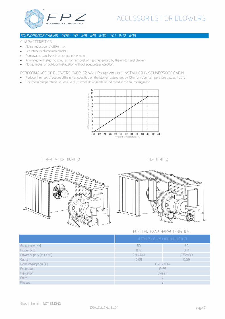
CHARACTERISTICS: • Noise reduction 10 dB(A) max. • Structure in aluminium blocks. • Removable panels with block-panel system. • Arranged with electric axial fan for removal of heat generated by the motor and blower. • Not suitable for outdoor installation without adequate protection. PERFORMANCE OF BLOWERS (MOR IE2 Wide Range version) INSTALLED IN SOUNDPROOF CABIN • Reduce the max. pressure differential specified on the blower data sheet by 10% for room temperature values ≤ 20°C • For room temperature values > 20°C, further downgrade as indicated in the following graph
IH7R-IH7-IH9-IH10-IH13 IH8-IH11-IH12
ELECTRIC FAN CHARACTERISTICS
IH7R-IH7-IH8-IH9-IH10-IH11-IH12-IH13
Frequency [Hz] 50 60 Power [kW] 0.12 0.14 Power supply [V ±10%] 230/400 275/480 Cos f 0.69 0.69 Nom. absorption [A] 0.70 / 0.44 Protection IP 55 Insulation Class F Poles 2 Phases 3
0 1 2 3 4 5 6 7 8 9
10 11 12
20 22 24 26 28 30 32 34 36 38 40 42 44 Ambient temperature °C
diff
eren
tial p
ress
ure
redu
ctio
n in
%
ACCESSORIES FOR BLOWERS
Sizes in [mm] - NOT BINDING DSA_EU_EN_16_04 page 22
DIMENSIONS (IH7R-IH7-IH9-IH10-IH13)
Model Blower type Spacer1 A B C D G H I L M O P Q R [Kg]
1 Required for use of filter “FL” 2 Required only for blower K08-MS with 9.2 kW electric motor 3 Required only for blower K09/K10-MS with 9.2 kW and 11 kW, K11/K12-MS with 15 kW and 18.5 kW, K12-MD with 15 kW electric motor 4 Not applicable with 22 kW motor
(a) Electric axial fan (b) Electrical cables input (c) Accessory FL (d) Accessory CA (e) Spacer1
( a ) ( c )
( d )
( e )
( b )
ACCESSORIES FOR BLOWERS
Sizes in [mm] - NOT BINDING DSA_EU_EN_16_04 page 23
(a) Electric axial fan (b) electrical cables input
( a )
( b )
ACCESSORIES FOR BLOWERS
Sizes in [mm] - NOT BINDING DSA_EU_EN_16_04 page 24
ACCESSORIES SUITABLE FOR ATEX ENVIRONMENT
PRESSURE MEASUREMENTS
MECHANICAL ELECTRONIC
Model MC030 MA040 TC420 TC010 TA420 TA010
Characteristics
Bourdon tube pressure gauge in steel, ideal for industrial-type use
Pressure transducer, accurate and reliable, suitable for use in heavy industrial environments. Allows acquisition of status and control of the system in question
ATEX classification II 2 GDc T6 II 1 GD – Ex ia IIC T5 Range 0 … 1000 mbar -1000 … 0 mbar 0 … 1000 mbar -1000 … 0 mbar
Power supply - 14-28 VDC Output signal - 4-20 [mA]
Electrical connection - DIN EN 175301-803 Protection IP 65 IP 65
Dimensions
1 The accuracy decreases by 0.6% FS every 10°C above 100°C
43
Ø8
55
Ø68
G1/4 Ch 27
20
Ø3
Ø27
12
74
48
G1/4
Ch 27
25
ACCESSORIES FOR BLOWERS
Sizes in [mm] - NOT BINDING DSA_EU_EN_16_04 page 26
FILTER
A device that stops particles of dust or debris carried by the gas, protecting the side channel blower as well as possible adjustment and safety devices. To be used with non-aggressive gases, such as manufactured gas (carbon monoxide), methane (natural gas) and LPG (liquefied petroleum gas).
Characteristics:
- Casing in cast aluminium (dimensions 230mm x 150mm) - Filter element in washable synthetic material (viledon). - Standard degree of filtration: 20 µm - Filtering surface area: 10650 mm² - Possible vertical installation - Supplied with gaskets and screws for connection to the system - Arranged for pressure sampling points upstream and downstream of the cartridge (G ¼”) - EC approval according to EN 126 - In conformity with Directive 2009/142/EC (Gas Directive) - In conformity with the 97/23/EC (PED)
Available on request: - degree of filtration 50 and 10 µm. - version treated (cataphoresis) for compatibility with work fluid containing H2S
ANTIVIBRATION JOINTS
A device allowing the machine to be uncoupled from the system, preventing the transmission of vibration and allowing the adjustment of any misalignments.
Characteristics:
- In AISI 316L stainless steel - Anti-twisting grooving to avoid problems during assembly - Supplied with gaskets and screws for connection to the system
FILT
ER
Model Flanged
connections Filtration
degree [µm]
Weight
[kg]
FF40J10 DN 40
10 2,55 FF40J20 20
FF40J50 50 FF50J10
DN 50 10
2,70 FF50J20 20 FF50J50 50
CART
RID
GE
Model Filter Dimensions
Weight
[g]
25CF10M FF40J10
140 x 105 x 35 56
FF50J10
25CF20M FF40J20 FF50J20
25CF50M FF40J50 FF50J50
ACCESSORIES FOR BLOWERS
DSA_EU_EN_16_04 page 27
FPZ Espana/Portugal Pral, Barcelona Espana [email protected] HEADQUARTERS