Energy Equip. Sys./ Vol. 5/No2/June 2017/ 115-129 Energy Equipment and Systems http://energyequipsys.ut.ac.ir www.energyequipsys.com Accurate power sharing for parallel DGs in microgrid with various-type loads Authors Abbas Ketabi a Sahbasadat Rajamand a* Mohammad Shahidehpour b a Department of Electrical Engineering, Kashan University, Kashan, Iran b Illinois Institute of Technology, Chicago, USA ABSTRACT Microgrid has been recently used to produce electric energy with more efficiency and greater advantages. However, it has some challenges. One of the main problems of microgrids that are widely used in electric power systems is encountered in controlling its voltage, frequency, and load-share balancing among inverter-based Distributed Generations (DGs) in the islanded mode. The droop method performance is degraded when the feeder impedances of the two DGs are different, and therefore, modification is needed. In this paper, a new method based on virtual impedance and compensating voltage is proposed, and simulation results show that this method, in combination with droop control, results in balanced power sharing with negligible voltage and frequency drop. Simulation results extracted from the Simulink, MATLAB show that the proposed method has a satisfactory performance in equal load sharing between the two DGs with different feeder impedances, both in equal and in different droop gains, with different loads such as nonlinear loads. Article history: Received : 5 September 2016 Accepted : 28 December 2016 Keywords: Microgrid, Compensating Voltage, Power Sharing, inverter, Virtual Impedance, Nonlinear- Unbalanced Load. 1. Introduction Changing climate and consuming patterns have a significant effect on electricity generation methods. A considerable number of countries have been focusing on reducing greenhouse gases by 2020 Majumder [1]. In terms of distribution levels, renewable resources such as photovoltaic, wind turbine, fuel cell, and other resources, can connect to a main grid and produce a substantial amount of electric energy and thus these resources are called Distributed Energy Resources (DER), or DG. In present times, fuel costs are increasing and geographical problems provide *Corresponding author: Sahbasadat Rajamand Address: Department of Electrical Engineering, Kashan University, Kashan, Iran E-mail address: [email protected]a new opportunity to use DERs in electric power systems. The microgrid is defined as the set of DERs in the electric power system, which includes DGs, storage systems and linear, unbalanced, or nonlinear loads; these can be connected to the main grid or they can be islanded. The presence of several DGs in the microgrid brings about certain challenges that affect system performance. When the microgrid is connected to the main grid, the voltage and frequency is supported by the main grid. One of the main challenges of this arrangement involves the frequency and the voltage control of microgrid in the islanded mode, especially when various loads are connected or disconnected, and voltage and frequency drop may be common in this
Accurate power sharing for parallel DGs in microgrid with various-type loads Authors
Abbas Ketabi a
Sahbasadat Rajamand a*
Mohammad Shahidehpour
b
a Department of Electrical Engineering,
Kashan University, Kashan, Iran b Illinois Institute of Technology,
Chicago, USA
ABSTRACT
Microgrid has been recently used to produce electric energy with more efficiency and greater advantages. However, it has some challenges. One of the main problems of microgrids that are widely used in electric power systems is encountered in controlling its voltage, frequency, and load-share balancing among inverter-based Distributed Generations (DGs) in the islanded mode. The droop method performance is degraded when the feeder impedances of the two DGs are different, and therefore, modification is needed. In this paper, a new method based on virtual impedance and compensating voltage is proposed, and simulation results show that this method, in combination with droop control, results in balanced power sharing with negligible voltage and frequency drop. Simulation results extracted from the Simulink, MATLAB show that the proposed method has a satisfactory performance in equal load sharing between the two DGs with different feeder impedances, both in equal and in different droop gains, with different loads such as nonlinear loads.
Article history:
Received : 5 September 2016 Accepted : 28 December 2016
Keywords: Microgrid, Compensating Voltage, Power Sharing, inverter, Virtual Impedance, Nonlinear-
Unbalanced Load.
1. Introduction
Changing climate and consuming patterns have a significant effect on electricity generation methods. A considerable number of countries have been focusing on reducing greenhouse gases by 2020 Majumder [1]. In terms of distribution levels, renewable resources such as photovoltaic, wind turbine, fuel cell, and other resources, can connect to a main grid and produce a substantial amount of electric energy and thus these resources are called Distributed Energy Resources (DER), or DG. In present times, fuel costs are increasing and geographical problems provide *Corresponding author: Sahbasadat Rajamand Address: Department of Electrical Engineering, Kashan University, Kashan, Iran E-mail address: [email protected]
a new opportunity to use DERs in electric power systems. The microgrid is defined as the set of DERs in the electric power system, which includes DGs, storage systems and linear, unbalanced, or nonlinear loads; these can be connected to the main grid or they can be islanded.
The presence of several DGs in the microgrid brings about certain challenges that affect system performance. When the microgrid is connected to the main grid, the voltage and frequency is supported by the main grid. One of the main challenges of this arrangement involves the frequency and the voltage control of microgrid in the islanded mode, especially when various loads are connected or disconnected, and voltage and frequency drop may be common in this
116 Abbas Ketabi et al./ Energy Equip. Sys. / Vol. 5/No.2/June 2017
arrangement, in which voltage and frequency distortion cannot be avoided. The voltage and frequency control of the microgrid was, therefore, mainly considered in many papers and researches.
The primary attribute of microgrid control is the stability of voltage and frequency, which has been considered in many papers. Low frequency stability owing to power demand changes is discussed in Vilathgamuwa et al. [2], whereby, low frequency displacement to a new status due to power demand changes has affected the relative stability of the system. Robust stability of voltages and currents for islanded DGs was analysed in Marwali et al. [3], in which discrete-time slipping mode control was used. In Marwali et al. [4], small signal stability analysis was performed by a combination of droop control and the power averaging method for power sharing in several islanded DGs. Droop control is one of the most applicable and useful control methods based on the behaviour of the Synchron Generator of power systems. In this method, the control of real and reactive power sharing is adjusted using output frequency and voltage adjustment, respectively. Droop control does not need communication links. Certain advantages (such as simplicity) and disadvantages (such as compromising between voltage adjustment and load sharing) of the droop method are discussed in Chandorkar et al., Guerrero et al., Guerrero et al. [ 5–7]. In some researches, such as Katiraei and Iravani, Azim et al. [8, 9], the control of the real and the reactive power of electronic-interfaced DGs in the microgrid have been investigated. Robust control with harmonic suppression in the islanding mode and power control without coupling in the grid-connected mode was discussed in Reza et al., Zhong [10, 11]. The Load sharing using inherently oscillatory droop control was improved by PI control in Guerrero et al. [12].
Transient sharing was also improved and resulted in frequency and current stability. In Paquette and Divan [13], transient power sharing was improved using virtual impedance current limiting.
In the microgrid, it is desirable that all DGs respond similarly to the load steps in order to avoid overload of certain lead or lag DGs. When the impedances of the two inverter-based DGs are not equal, the DG with smaller impedance has a quicker response to the load steps and picks up more power shared. To overcome the droop control drawbacks in the load sharing of different DGs, modifications
have been applied in certain studies. To correct the compromise of voltage adjustment and load sharing, feedback control in Kim et al., Katiraei et al. [14, 15], dynamic coefficients in Diaz et al., Lee et al. [16, 17], and phase droop instead of frequency droop in Sao and Lehn [18] have been used. For harmonic load sharing correction, the method of extra loop for bandwidth in Sao and Lehn [19] and virtual impedance in Marwali et al., Lee and Cheng., Vasquez et al., He et al [20–23] were proposed. In addition, cooperative harmonic filtering was suggested in Li and W. Li [24]. To control the degradation of coupling inductors, the virtual impedance method Marwali et al. [20], the variable virtual impedance in Lee and Cheng, Vasquez et al. [21, 22], and a method based on virtual power for active and reactive power decoupling for droop-controlled parallel inverters were stated in Wu et al. [25]. To mitigate the problem of feeder impedances, an extra loop for grid impedance estimation was used in Yao et al. [26]. With respect to the issue of slow dynamic response, phase droop Yazdani et al. [27], adaptive decentralized droop McGrath et al. [28], droop based on coupling filter parameters Lee et al. [29], and adaptive droop gains Yazdani and Iravani [30] have been proposed. For the assembly of DGs, nonlinear droop control Lee and Cheng [21], and a combination of droop control, MPPT Li and W. Li [24], and power management of DGs Yazdani et al. [27] were applied.
Some studies apply integrated control strategies called hierarchical structures, which usually include primary, secondary, and tertiary control Wu et al., Yao et al., Yazdani et al. [25–27]. Primary control is used for the stability of voltage and frequency. The secondary control, as a centralized controller, is the compensator for voltage and frequency oscillations. Tertiary control provides the optimal power flowing within the microgrids. Cooperative distributed hierarchical control has also been proposed in McGrath et al. [28], which uses voltage, active and reactive power regulators to adjust the voltage and the frequency of inverters.
In this paper, our purpose is to equalize the power sharing between two DGs by controlling the voltage and the frequency of the test microgrid in the islanded mode. This paper uses a new method that includes the two following steps: virtual impedance and compensating voltage. Virtual impedance is used for transient power sharing. Compensating voltage step is used to model
Abbas Ketabi et al./ Energy Equip. Sys. / Vol. 5/No.2/June 2017 117
and estimate the relation of impedance differences and the real and the reactive powers; therefore, the voltage drop difference is compensated in the steady state. This approach thus equalizes the real and reactive power sharing between two inverters with different feeder impedances. The simulation results verify this method.
The remainder of this paper is organized as follows: in Section II, the test microgrid model is proposed and the proposed method is discussed in Section III. In Section IV, the simulation results have been shown, while in Section V, the Total Harmonic Distortion is discussed. Finally, the conclusion is stated in the final section of this paper, Section VI.
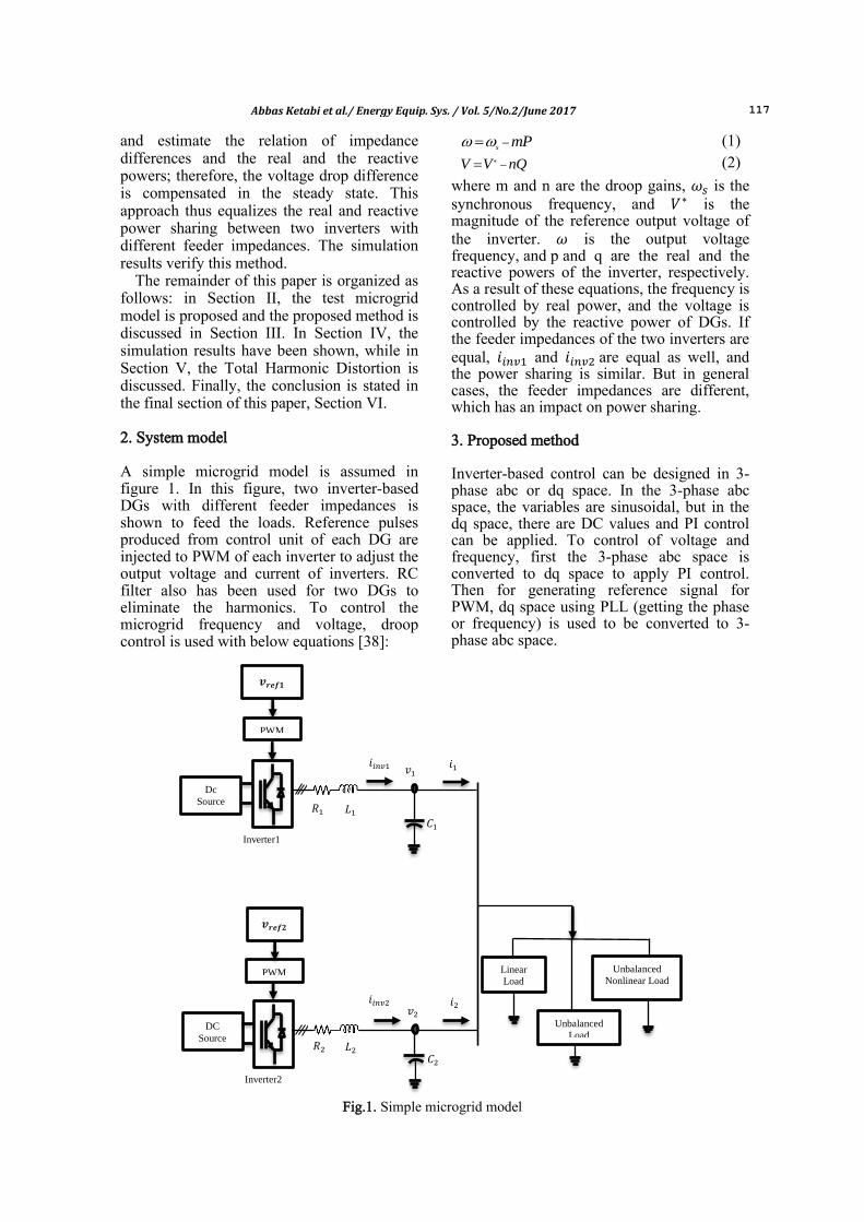
2. System model A simple microgrid model is assumed in figure 1. In this figure, two inverter-based DGs with different feeder impedances is shown to feed the loads. Reference pulses produced from control unit of each DG are injected to PWM of each inverter to adjust the output voltage and current of inverters. RC filter also has been used for two DGs to eliminate the harmonics. To control the microgrid frequency and voltage, droop control is used with below equations [38]:
s mP (1)
V V nQ (2)
where m and n are the droop gains, is the synchronous frequency, and is the magnitude of the reference output voltage of the inverter. is the output voltage frequency, and p and q are the real and the reactive powers of the inverter, respectively. As a result of these equations, the frequency is controlled by real power, and the voltage is controlled by the reactive power of DGs. If the feeder impedances of the two inverters are equal, and are equal as well, and the power sharing is similar. But in general cases, the feeder impedances are different, which has an impact on power sharing. 3. Proposed method Inverter-based control can be designed in 3-phase abc or dq space. In the 3-phase abc space, the variables are sinusoidal, but in the dq space, there are DC values and PI control can be applied. To control of voltage and frequency, first the 3-phase abc space is converted to dq space to apply PI control. Then for generating reference signal for PWM, dq space using PLL (getting the phase or frequency) is used to be converted to 3-phase abc space.
Fig.1. Simple microgrid model
Inverter2
Inverter1
𝒗𝒓𝒆𝒇𝟐
PWM
𝐶
PWM
𝒗𝒓𝒆𝒇𝟏
𝑖𝑖𝑛𝑣 𝑖 𝑣
𝑅 𝐿
Dc
Source
Unbalanced
Nonlinear Load
𝐶
𝑖𝑖𝑛𝑣 𝑖 𝑣
𝑅 𝐿
DC
Source
Unbalanced
Load
Linear
Load
118 Abbas Ketabi et al./ Energy Equip. Sys. / Vol. 5/No.2/June 2017
The common droop method is one of the most applicable and simplest methods for voltage and frequency control in the microgrid system, but the main defect of this method is its unbalanced initial load sharing between DGs when the load changes in the system. According to Fig.1, the feeder impedances of two DGs are not equal and DG with smaller impedance picks up more power in relation to another DG with greater impedance. Certain studies suggest the use of transient droop or adaptive droop for overcoming this effect, but these methods degrade load sharing, voltage, and frequency in the steady state. Our purpose in this paper is to suggest a method across both, the transient and the stable mode, in which the load sharing will be equalized between the two DGs, and the frequency and the voltage drop will be negligible.
In order to apply the proposed method, the dq space is used. In a control unit of the proposed algorithm, therefore, all the voltages and currents should be transformed from abc to dq, and the real and the reactive power must be calculated within this coordination.
The proposed method consists of two steps which are discussed below:
A. Virtual Impedance In the first step, the voltage drop on DG with smaller impedance must be modified. In other words, it is obvious that the voltage of DG with greater impedance cannot be reduced because this is not available. The impedance of DG with smaller impedance can, therefore, be increased virtually in the control unit to equalize the voltage loss in the two DG feeder circuits. If there has been a method to equalize the impedances, the voltage drops will be equal; this ensures a similarity of the load sharing between the two DGs. The difference between the two impedances particularly affects reactive power sharing because the reactive power is justified by the voltage. In this paper, it is assumed that the impedance of DG1 is smaller. As mentioned previously, it is impossible to apply the real impedance in the feeder of DG1; therefore, virtual impedance must be used to modify the difference of the voltage drops. The virtual impedance effect is more obvious in transient load sharing and less effective in the stable mode. Therefore, in the first step of the proposed method, the virtual impedance can be used as shown below Lee et al., Yazdani and Iravani [29, 30]:
VI VI VIjZ R X (3)
,d VI VI d VI qV R i X i (4)
q,VI VI q VI dV R i X i (5)
These equations are depicted in Fig.2a and Fig.2b.
Fig. 2. Virtual impedance in a) q-axis and b) d-axis
For the stability of the proposed method in transient power sharing and the least sensitivity to a change of feeder impedances of the two inverters as well as a change of different loads, such as common linear, unbalanced, and nonlinear-unbalanced loads, the coefficient of applied virtual impedance is updated due to equation below in the case of equal droop gain:
1 2Q Q Q (6)
This difference is thereafter controlled by the PI controller to remain near to zero in the transient mode as shown in Fig.3.
It is noticeable that the values of and are only the initial values or initial guesses of the feeder impedance difference; the exact values are not primarily considered. In fact, the real values of feeder impedances are not available Sao and Lehn [19]. This is of no concern because the feedback structure of Figs. 3a and 3b are sufficient for the stability and the convergence of the transient mode of the control circuit.
In the case of different droop gain, the Eq.(6) differs as shown below (for example, the droop gain of Inverter 1 becomes double):
1 22Q Q Q (7)
This is a result of different power sharing between the two inverters and Inverter 1 picks more power of load as double the load sharing capacity of Inverter 2.
Abbas Ketabi et al./ Energy Equip. Sys. / Vol. 5/No.2/June 2017 119
(a)
(b)
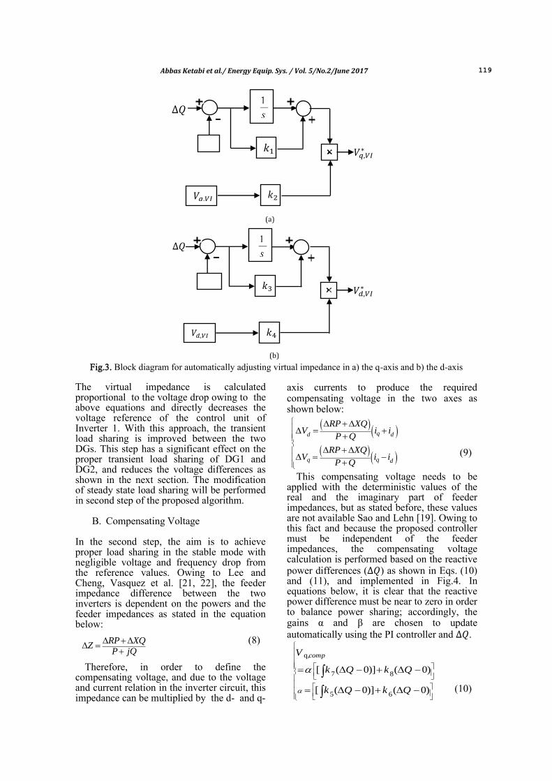
Fig.3. Block diagram for automatically adjusting virtual impedance in a) the q-axis and b) the d-axis
The virtual impedance is calculated proportional to the voltage drop owing to the above equations and directly decreases the voltage reference of the control unit of Inverter 1. With this approach, the transient load sharing is improved between the two DGs. This step has a significant effect on the proper transient load sharing of DG1 and DG2, and reduces the voltage differences as shown in the next section. The modification of steady state load sharing will be performed in second step of the proposed algorithm.
B. Compensating Voltage In the second step, the aim is to achieve proper load sharing in the stable mode with negligible voltage and frequency drop from the reference values. Owing to Lee and Cheng, Vasquez et al. [21, 22], the feeder impedance difference between the two inverters is dependent on the powers and the feeder impedances as stated in the equation below:
RP XQZ
P jQ
(8)
Therefore, in order to define the compensating voltage, and due to the voltage and current relation in the inverter circuit, this impedance can be multiplied by the d- and q-
axis currents to produce the required compensating voltage in the two axes as shown below:
qd d
q q d
RP XQV i i
P Q
RP XQV i i
P Q
(9)
This compensating voltage needs to be applied with the deterministic values of the real and the imaginary part of feeder impedances, but as stated before, these values are not available Sao and Lehn [19]. Owing to this fact and because the proposed controller must be independent of the feeder impedances, the compensating voltage calculation is performed based on the reactive power differences ( ) as shown in Eqs. (10) and (11), and implemented in Fig.4. In equations below, it is clear that the reactive power difference must be near to zero in order to balance power sharing; accordingly, the gains α and β are chosen to update automatically using the PI controller and .
q,
7 8
5 6
[ ( 0)] ( 0)
[ ( 0)] ( 0)
compV
k Q k Q
k Q k Q
(10)
𝑄
𝑉𝑞,𝑉𝐼
𝑘 𝑉𝑞,𝑉𝐼
𝑘
𝑄
𝑉𝑑,𝑉𝐼
𝑘3 𝑉𝑑,𝑉𝐼
𝑘4
120 Abbas Ketabi et al./ Energy Equip. Sys. / Vol. 5/No.2/June 2017
(a)
(b)
Fig.4. a) The block diagram of , . and b) the block diagram of ,
11 12d,
9 10
[ ( 0)] ( 0)
[ ( 0)] ( 0)
compV k Q k Q
k Q k Q
(11)
By applying the PI controller, which is the same as virtual impedance, the weighted , and , can be automatically updated proportional to the new amount of feeders’ impedance and for any kind of load. The general control unit of the proposed algorithm, including the voltage and the frequency control of , are shown in Fig. 5. The control unit of Inverter 2 is similar to that of Inverter 1, except that the virtual impedance and compensating voltage will not be applied in this control circuit as it is assumed that the feeder impedance of Inverter 1 is smaller than the feeder impedances of Inverter 2.
(a)
(b)
𝑄 𝑘5
0 𝑘6
𝑘7
𝑉𝑞,𝑐𝑜𝑚𝑝
0 𝑘8
𝑄 𝑘9
0
0 𝑘 0
𝑘
𝑣𝑑,𝑐𝑜𝑚𝑝
0
0
𝑘
𝑉𝑑,𝑐𝑜𝑚𝑝
𝑉𝑑 𝑢 𝑑
𝑉𝑑 ,𝑉𝐼
𝑣𝑑
𝐾 5
𝑉𝑞
𝑚𝑞
𝑄
𝑘 3
𝑉𝑞,𝑐𝑜𝑚𝑝
𝑘 4 𝑉𝑞 ,𝑉𝐼
𝑉𝑞
𝑢 𝑞
Abbas Ketabi et al./ Energy Equip. Sys. / Vol. 5/No.2/June 2017 121
(c)
Fig.5. Control unit of a) q-axis voltage control b) d-axis voltage control c) frequency control
Finally, the reference voltage signal, in
abc space, is produced and used as a command signal for the PWM of the inverter to control the voltage and frequency of each DG.
The flowchart of the system and control unit is shown in the Fig.6.
The proposed algorithm, as shown in the next section, has a good performance in real and reactive power sharing in both, the transient and the stable modes. 4. Simulation results The proposed algorithm was simulated with the Simulink of MATLAB, using the simpower toolbox. The simulation parameters are given in Table 1.
Before a discussion of the results, it should
be noted that the values were stated in per unit (P.U.).
In the simulation results, first we investigated power sharing between linear, unbalanced, and nonlinear-unbalanced loads, separately, in different interval times. Then, in the case of the combination of these three loads, which were simultaneously connected to the test microgrid, power sharing was analysed. In the following section, the simulation results of reactive power sharing are firstly discussed and thereafter the same process is performed for real power sharing.
A. Equal Droop Gain (1:1) 1) Reactive Power Sharing 1-1) Power Sharing with Virtual Impedance
Figure 7 shows the reactive power sharing with (Step 1 of the algorithm). As shown in this figure, it can be concluded that affects transient power sharing and by applying , the transient part is balanced, and the two inverters track each other without any overshoot in the transient case. In addition, it can be seen that the steady state part is not balanced because the feeder impedances are different, and this difference causes a stability error in steady state reactive power sharing, even with the equal droop gains of the two DGs.
Fig.6. The flowchart of system and control unit
2𝜋𝑓0
𝑚𝑝
1
2𝜋
𝑓
v
1
𝑠
𝑃
v
𝜃
122 Abbas Ketabi et al./ Energy Equip. Sys. / Vol. 5/No.2/June 2017
Table 1.Simulation Parameters
Parameters Value
Frequency (Hz) 60
Voltage (Volt) 220
Frequency droop slope ((rad/s)/ ), 2*pi
Voltage droop slope ( / , 0.05
= 3 ( PI proportional virtual impedance Gain, inv1, q-axis and d-axis, respectively)
1
(virtual impedance Gain, inv1, q-axis) 0.1
4 (virtual impedance Gain, inv1, d-axis) 0.05
5= 9 ( , PI integration Gain, inv1, q-axis and d-
axis, respectively)
30
6 = 8 ( , PI proportional Gain, inv1, q-axis) 2
7= ( , PI proportional Gain, inv1, q-axis and d-
axis, respectively)
500
0= ( , PI proportional Gain, inv1, d-axis) 2
3 (PI proportional voltage Gain, inv1, d-axis) 0.95
4 = 5 (output voltage Gain, inv1, q-axis and d-axis, respectively)
0.1
Feeder impedance 1 1.1+j1.5
Feeder impedance 2 1.6+j2.45
RC filter C=15 f,
R=20
Fig.7. Reactive power sharing using the virtual impedance
1-2) Power Sharing with Proposed Method
The reactive power sharing result using the proposed method (virtual impedance and compensating voltage) has been shown in Fig.8. Both transient and stable load sharing are balanced between two DGs and inverters
track each other. Really although with different feeder impedances, the proposed method by addition of the has compensated the voltage drop difference in stability mode and the reactive power sharing is equalized as if the conditions of two inverters were similar.
Abbas Ketabi et al./ Energy Equip. Sys. / Vol. 5/No.2/June 2017 123
2) Real Power Sharing 2-1) Power Sharing with Compensating
Voltage
Real power sharing, with the application of Step 2 of the algorithm (compensating voltage), has been shown in Fig.9. By using the compensating voltage, the steady state mode becomes balanced. The compensating voltage has thus affected the steady state mode in real power sharing. Figure 9 shows that only the transient power sharing degraded, especially for linear and nonlinear-unbalanced loads due to the impedance differences between the two DGs. Inverter 1 overshoots when the load is connected and picks more power off the loads. As transient time passed, the load sharing was approximately equalized.
2-2) Power Sharing with the Proposed Method
In Fig.10, it is shown that using the proposed method (virtual impedance and compensating voltage), both transient and stable real power sharing have been balanced and the two DGs track each other with equal droop gains and different feeder impedances. It can be concluded that virtual impedance has an effects on the transient mode and the compensating voltage has an effects on the stability mode.
B. Different Droop Gains (2:1) In this section, the behaviour of the test microgrid under different feeder impedances and different droop gains is discussed. In the simulation results, it has been shown that the
Fig.8. Reactive power sharing using the proposed algorithm
Fig.9. Real power sharing with compensating voltage
124 Abbas Ketabi et al./ Energy Equip. Sys. / Vol. 5/No.2/June 2017
active and the reactive power is shared between the two DGs proportional to the relation of droop gains in the proposed method. The simulation parameters are the same as those depicted in Table 1.
1) Power Sharing Accuracy To investigate the accuracy of power sharing of the proposed method in different droop gains, the accuracy error parameter is defined and analysed as shown below:
0100% ref
ref
Q Qaccuracy error
Q
(12)
The accuracy error percentage is shown in the figures with different droop gains. It can be seen that when the various loads are connected to the microgrid without the proposed method, the accuracy error is increased. By applying the proposed method, however, the accuracy of power sharing is not degraded and it is bound to a small value near zero.
2) Reactive Power Sharing
2-1) Power Sharing with Virtual Impedance
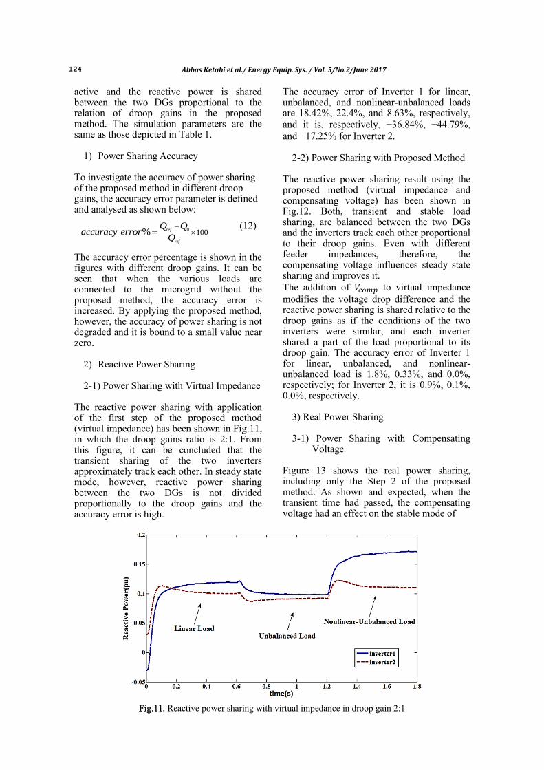
The reactive power sharing with application of the first step of the proposed method (virtual impedance) has been shown in Fig.11, in which the droop gains ratio is 2:1. From this figure, it can be concluded that the transient sharing of the two inverters approximately track each other. In steady state mode, however, reactive power sharing between the two DGs is not divided proportionally to the droop gains and the accuracy error is high.
The accuracy error of Inverter 1 for linear, unbalanced, and nonlinear-unbalanced loads are 18.42%, 22.4%, and 8.63%, respectively, and it is, respectively, −36.84%, −44.79%, and −17.25% for Inverter 2.
2-2) Power Sharing with Proposed Method
The reactive power sharing result using the proposed method (virtual impedance and compensating voltage) has been shown in Fig.12. Both, transient and stable load sharing, are balanced between the two DGs and the inverters track each other proportional to their droop gains. Even with different feeder impedances, therefore, the compensating voltage influences steady state sharing and improves it. The addition of to virtual impedance modifies the voltage drop difference and the reactive power sharing is shared relative to the droop gains as if the conditions of the two inverters were similar, and each inverter shared a part of the load proportional to its droop gain. The accuracy error of Inverter 1 for linear, unbalanced, and nonlinear-unbalanced load is 1.8%, 0.33%, and 0.0%, respectively; for Inverter 2, it is 0.9%, 0.1%, 0.0%, respectively.
3) Real Power Sharing 3-1) Power Sharing with Compensating
Voltage Figure 13 shows the real power sharing, including only the Step 2 of the proposed method. As shown and expected, when the transient time had passed, the compensating voltage had an effect on the stable mode of
Fig.11. Reactive power sharing with virtual impedance in droop gain 2:1
Abbas Ketabi et al./ Energy Equip. Sys. / Vol. 5/No.2/June 2017 125
Fig.12. Reactive power sharing using the proposed method with droop gain 2:1
Fig.13. real power sharing with using compensating voltage in droop gain 2:1
real power sharing, and it was approximately divided in the ratio of 2:1. In addition, we can see that the transient power sharing was degraded due to the impedance difference between the two DGs. In fact, DG2 overshoots in the time load connected and picks more power to support the load as a result of smaller impedance. The accuracy error of Inverter 1 for the linear, unbalanced, and nonlinear-unbalanced load was −12%, −0.31%, and 0.8%, respectively; for Inverter 2, it was 0.06%, 0.15%, and −0.44%, respectively.
3-2) Power Sharing with the Proposed Method
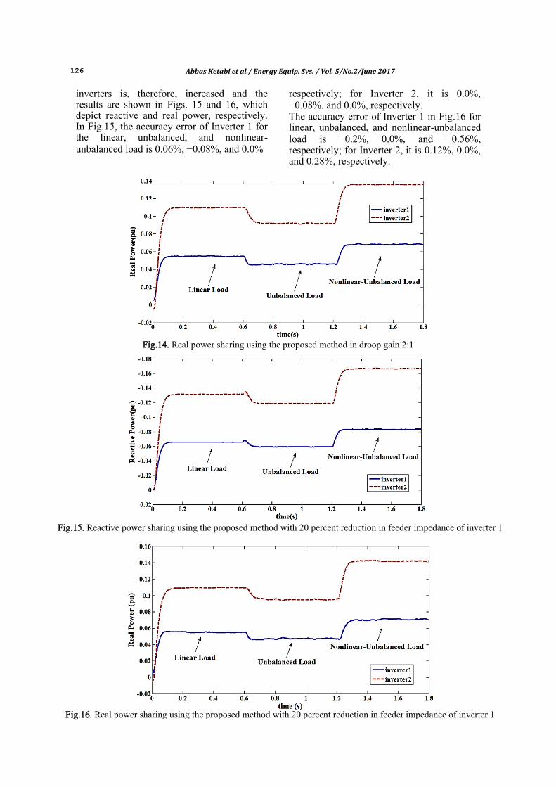
In Fig.14, it is shown that using the proposed method, both the transient and the stable real power is shared accurately due to droop gain ratio of 2:1. It can be seen that with different feeder impedances, the two inverters track each other in such a way that Inverter 2 picks double the power in comparison to Inverter 1.
In addition, by the addition of virtual impedance, the transient part of Fig.13 was modified and the result was improved: the accuracy error of Inverter 1 for linear, unbalanced, and nonlinear-unbalanced load was −0.03%, −0.1%, and −0.1%, respectively; for Inverter 2, it was 0.06%, 0.36%, and 0.23%, respectively.
C. Investigation of the Feeder Impedance Change on Power Sharing:
1) Reducing Feeder Impedance of Inverter
1 (20 Percent) The purpose of this section is to test the robustness of the proposed method under conditions of greater difference between the feeder impedances of the two inverters. Therefore, the feeder impedance of Inverter 1 with smaller impedance is reduced by about 20 percent from its first value, while the feeder impedance of Inverter 2 is kept unchanged. The impedance difference of two
126 Abbas Ketabi et al./ Energy Equip. Sys. / Vol. 5/No.2/June 2017
inverters is, therefore, increased and the results are shown in Figs. 15 and 16, which depict reactive and real power, respectively. In Fig.15, the accuracy error of Inverter 1 for the linear, unbalanced, and nonlinear-unbalanced load is 0.06%, −0.08%, and 0.0%
respectively; for Inverter 2, it is 0.0%, −0.08%, and 0.0%, respectively. The accuracy error of Inverter 1 in Fig.16 for linear, unbalanced, and nonlinear-unbalanced load is −0.2%, 0.0%, and −0.56%, respectively; for Inverter 2, it is 0.12%, 0.0%, and 0.28%, respectively.
Fig.14. Real power sharing using the proposed method in droop gain 2:1
Fig.15. Reactive power sharing using the proposed method with 20 percent reduction in feeder impedance of inverter 1
Fig.16. Real power sharing using the proposed method with 20 percent reduction in feeder impedance of inverter 1
Abbas Ketabi et al./ Energy Equip. Sys. / Vol. 5/No.2/June 2017 127
As seen from these figures, the proposed method has a good performance in this case as well and the two inverters track each other in the case of real and reactive power.
3) Increasing Feeder Impedance of Inverter 2 (20 Percent)
In this test case, the impedance feeder of Inverter 2 is increased up to 20 percent when the feeder impedance of Inverter 1 is fixed. The results are shown in Figs. 17 and 18, in which the proposed method’s robustness to feeder impedance changes can be observed. 5. Conclusion In this paper, we have suggested a method that consists of two steps. Virtual impedance and compensating voltage are applied to balance the real and the reactive power sharing between the two DGs with different feeder impedances, and with equal and different droop gains. The simulation results
show that the proposed algorithm has noticeably improved the transient and stable reactive power sharing. In fact, the reactive power is controlled by the voltage, and the proposed method uses the compensating voltage to compensate the voltage drop differences; in consequence, the real and the reactive power sharing are balanced between the two DGs. References [1] Majumder R., Modeling Stability
Analysis and Control of Microgrid, Ph. D. Thesis, Queensland University of Technology (2010).
[2] Vilathgamuwa D. M., Loh P. C., Y. Li, Protection of Microgrids During Utility Voltage Sags, IEEE Transactions Industrial Electronics (2006)53: 1427-1436.
[3] Marwali M. N., Dai M., Keyhani A., Robust Stability Analysis of Voltage and Current Control for Distributed
Fig.17. Reactive power sharing using the proposed method with 20 percent addition in feeder impedance of inverter 2
Fig.18. Real power sharing using the proposed method with 20 percent addition in feeder impedance of inverter 2
128 Abbas Ketabi et al./ Energy Equip. Sys. / Vol. 5/No.2/June 2017
Generation Systems, IEEE Transactions Energy Conversion (2006) 21(2) 516-526.
[4] Marwali M. N., Dai M., Keyhani A., Stability Analysis of Load Sharing Control for Distributed Generation Systems, IEEE Transactions Energy Conversion (2007) 22(3): 737-745.
[5] Chandorkar M., Divan D., Decentralized Operation of Distributed UPS Systems, International Conference on Power Electronics, Drives and Energy Systems for Industrial Growth (1995) 1: 565–571.
[6] Guerrero J., Berbel N., De Vicuna L., Matas J., Miret J., Castilla M., Droop Control Method for the Parallel Operation of Online Uninterruptible Power Systems Using Resistive Output Impedance, IEEE Applied Power Electronics Conference and Exposition (APEC) (2005) 1716–1722.
[7] Guerrero J., De Vicuna L., Matas J., Castilla M., Miret J., Output Impedance Design of Parallel-Connected UPS Inverters with Wireless Load-Sharing Control” IEEE Transactions Industrial Electronics (2005) 52 (4) 1126–1135.
[8] Katiraei F., Iravani M. R., Power Management Strategies for a Microgrid with Multiple Distributed Generation Units, IEEE Transactions Power Systems (2006)21: 1821-1831.
[9] Azim M. I., Hossain M. A., Hossain M. J., Pota, H. R., Effective Power Sharing Approach for Islanded Microgrids, Smart Grid Technologies - Asia (ISGT ASIA), IEEE Innovative, Bangkok(2015)1-4.
[10] Reza M., Sudarmadi D., Viawan F. A., Kling W. L., Van Der Suis L., Dynamic Stability of Power Systems with Power Electronic Interfaced DG, In Power Systems Conference and Exposition, PSCE06, IEEE PES (2006)1423-1428.
[11] Zhong Q. C., Robust Droop Controller for Accurate Proportional Load Sharing Among Inverters Operated in Parallel, IEEETransactions on Industrial Electronics (2013)60(4):1281-1290.
[12] Guerrero J., De Vicuna L., Castilla J. M., Miret J., A Wireless Controller to Enhance Dynamic Performance of Parallel Inverter in Distributed Generation Systems, IEEE Transactions Power Electronics (2004) 19: 1205-1213.
[13] Paquette A. D., Divan D. M., Virtual Impedance Current Limiting for Inverters in Microgrids with Synchronous
Generators, IEEE Transactions Industry Applications (2015) 51(2): 1630-1638.
[14] Kim J., Guerrero J. M., Rodriguez P., Teodorescu R., Nam K., Mode Adaptive Droop Control with Virtual Output Impedances for an Inverter-Based Flexible AC Microgrid, IEEE Transactions Power Electronics (2011) 26(3): 689–701.
[15] Katiraei F., Iravani R., Hatziargyriou N., Dimeas A., Microgrids Management, IEEE Transactions Power Energy Magazine (2008) 6: 54–65.
[16] Diaz G., Gonzalez-Moran C., Gomez-Aleixandre J., Diez A., Scheduling of Droop Coefficients for Frequency and Voltage Regulation in Isolated Microgrids, IEEE Transactions Power Systems (2010) 25: 489–496.
[17] Lee C. T., Chu C. C., Cheng P. T., A New Droop Control Method for the Autonomous Operation of Distributed Energy Resources Interface Converters, IEEE Transactions Power Electronics (2013) 28(4): 1980–1993.
[18] Sao C. K., Lehn W., Autonomous Load Sharing of Voltage Source Converters, IEEE Transactions on Power Delivery (2005)20: 1009–1016.
[19] Sao C. K., Lehn W., Control and Power Management of Converter Fed Microgrids, IEEE Transactions on Power Systems (2008) 23: 1088–1098.
[20] Marwali M. N., Jung J. W., A. Keyhani, Control of Distributed Generation Systems–Part II: Load Sharing Control, IEEE Transactions Power Electronics (2004) 19: 1551–1561.
[21] Lee T. L., Cheng P. T., Design of a New Cooperative Harmonic Filtering Strategy for Distributed Generation Interface Converters in an Islanding Network, IEEE Transactions Power Electronics (2007) 22: 1919–1927.
[22] Vasquez J. C., Guerrero J. M., Luna A., Rodriguez P., Teodorescu R., Adaptive Droop Control Applied to Voltage-Source Inverters Operating in Grid-Connected and Islanded Modes, IEEE Transactions on Industrial Electronics (2009)56: 4088–4096.
[23] He J., Li Y. W., Guerrero J. M., An Islanding Microgrid Power Sharing Approach Using Enhanced Virtual Impedance Control Scheme, IEEE Transactions Power Electronics (2013) 28(11): 5272-5282.
Abbas Ketabi et al./ Energy Equip. Sys. / Vol. 5/No.2/June 2017 129
[24] Li Y., Li Y. W., Power Management of Inverter Interfaced Autonomous Microgrid Based on Virtual Frequency-Voltage Frame, IEEE Transactions Smart Grid (2011) 2: 30–40.
[25] Wu T., Liu Z., Liu J., Wang S., You Z., A Unified Virtual Power Decoupling Method for Droop-Controlled Parallel Inverters in Microgrids," in IEEE Transactions on Power Electronics (2016) 31(8) 5587-5603.
[26] Yao W., Chen M., Matas J., Guerrero J. M., Qian Z., Design and Analysis of the Droop Control Method for Parallel Inverters Considering the Impact of the Complex Impedance on the Power Sharing,IEEE Transactions on Industrial Electronics (2011) 58: 576–588.
[27] Yazdani D., Bakhshai A., Joos G., Mojiri M., A Nonlinear Adaptive Synchronization Technique for Grid-
Connected Distributed Energy Sources, IEEE Transactions on Power Electronics (2008) 23: 2181–2186.
[28] McGrath B. P., Holmes D. G., Galloway J. J. H., Power Converter Line Synchronization Using a Discrete Fourier Transform (DFT) Based on a Variable Sample Rate, Transactions on Power Electronics (2005) 20: 877–884.
[29] Lee S. J., Kim H., Sul S. K., Blaabjerg F., A Novel Control Algorithm for Static Series Compensators by Use of PQR Instantaneous Power Theory, IEEE Transactions on Power Electronics (2004)19: 814–827.
[30] Yazdani A., Iravani R., A Unified Dynamic Model and Control for the Voltage Source Converter under Unbalancedd Grid Conditions, IEEE Transactions on Power Delivery (2006) 21: 1620–1629.