104
Aspire 5920G Series Service Guide PRINTED IN TAIWAN Service guide files and updates are available on the ACER/CSD web; for more information, please refer to http://csd.acer.com.tw

Aspire 5920G SeriesService Guide
PRINTED IN TAIWAN
Service guide files and updates are availableon the ACER/CSD web; for more information,
please refer to http://csd.acer.com.tw

Revision HistoryPlease refer to the table below for the updates made on Aspire Chapla service guide.
Date Chapter Updates
II

CopyrightCopyright © 2007 by Acer Incorporated. All rights reserved. No part of this publication may be reproduced, transmitted, transcribed, stored in a retrieval system, or translated into any language or computer language, in any form or by any means, electronic, mechanical, magnetic, optical, chemical, manual or otherwise, without the prior written permission of Acer Incorporated.
DisclaimerThe information in this guide is subject to change without notice.
Acer Incorporated makes no representations or warranties, either expressed or implied, with respect to the contents hereof and specifically disclaims any warranties of merchantability or fitness for any particular purpose. Any Acer Incorporated software described in this manual is sold or licensed "as is". Should the programs prove defective following their purchase, the buyer (and not Acer Incorporated, its distributor, or its dealer) assumes the entire cost of all necessary servicing, repair, and any incidental or consequential damages resulting from any defect in the software.
Acer is a registered trademark of Acer Corporation.Intel is a registered trademark of Intel Corporation.Pentium and Pentium II/III are trademarks of Intel Corporation.Other brand and product names are trademarks and/or registered trademarks of their respective holders.
III

ConventionsThe following conventions are used in this manual:
SCREEN MESSAGES Denotes actual messages that appear on screen.
NOTE Gives bits and pieces of additional information related to the current topic.
WARNING Alerts you to any damage that might result from doing or not doing specific actions.
CAUTION Gives precautionary measures to avoid possible hardware or software problems.
IMPORTANT Reminds you to do specific actions relevant to the accomplishment of procedures.
IV

PrefaceBefore using this information and the product it supports, please read the following general information.
1. This Service Guide provides you with all technical information relating to the BASIC CONFIGURATION decided for Acer's "global" product offering. To better fit local market requirements and enhance product competitiveness, your regional office MAY have decided to extend the functionality of a machine (e.g. add-on card, modem, or extra memory capability). These LOCALIZED FEATURES will NOT be covered in this generic service guide. In such cases, please contact your regional offices or the responsible personnel/channel to provide you with further technical details.
2. Please note WHEN ORDERING FRU PARTS, that you should check the most up-to-date information available on your regional web or channel. If, for whatever reason, a part number change is made, it will not be noted in the printed Service Guide. For ACER-AUTHORIZED SERVICE PROVIDERS, your Acer office may have a DIFFERENT part number code to those given in the FRU list of this printed Service Guide. You MUST use the list provided by your regional Acer office to order FRU parts for repair and service of customer machines.
V

VI

System Specifications
Chapter 1
FeaturesBelow is a brief summary of the computer’s many features:
Operating systemGenuine Windows® VistaTM Capable
Genuine Windows® VistaTM Home Basic / Home Premium / Ultimate / Business Edition
Genuine Windows® XP Home / Professional Edition (Service Pack 2)
Genuine Windows® XP Media Center / Tablet Edition
Genuine Windows® 2000 (Service Pack 4)NOTE: Windows® VistaTM Capable PCs come with Windows® XP installed, and can be upgraded to
Windows® VistaTM. For more information on Windows® VistaTM and how to upgrade, go to: Microsoft.com/windowsvista.
Platform and memoryIntel® Mobile Merom mobile technology, featuring:
Intel® CoreTM Duo processor (4 MB L2 cache, 1.66/1.83/2/2.16 GHz, 800 MHz FSB) or higher
Intel® PM965 Chipset
Integrated Intel® PRO/Wireless 3945ABGN network connection (dual-band tri-mode 802.11a/b/g/n) Wi-Fi CERTIFIEDTM solution, supporting Acer SignalUpTM wireless technology
Core logic: Intel® Santa Rose Platform, Crestline 965GM+ICH8M (north bridge+ south bridge)
Up to 2GB of DDR2 533/677 MHz memory, upgradeable to 4GB using two soDIMM modules (dual-channel support)
Display and graphics15.4” WXGA+ high-brightness Acer CrystalBriteTM TFT LCD, 1680 x 1050 pixel resolution, 6 lamps
16 ms typical of/off and 8 ms average gray-to-gray response time
Simultaneous multi-window viewing via Acer VistaTM supported
Supporting NVIDIA® PureVideoTM technology (WMV HD, High-Definition MPEG-2 Hardware Acceleration, integrated HDTV encoder) dual-link DVI, Microsoft® DirectX® 10, Shader Model 4.0, OpenEXR High Dynamic Range (HDR) technology, Unified Shader Architecture, Geometry Instancing 2.0, SGI OpenGL® 2.0 Optimizations and support, SmartDimmerTM Technology and PCI Express®
Dual independent display
16.7 million colors (20.1” LCD model)
16.2 million colors (19” LCD model)
MPEG-2/DVD hardware-assisted capability
S-video/TV-out (NTSC/PAL) support
Acer ArcadeTM featuring Acer CinemaVisionTM and Acer ClearVision technologies
Chapter 1 1

AudioIntel® High Definition audio support
Two built-in Acer 3DSonic stereo speakers (1W)
Realtek ALC268 Audio Code with Dolby®
Sound Blaster ProTM and MS Sound compatible
Built-in microphone
VoIP-enabled
Storage subsystemOne or two 60/80/100/120 GB Serial ATA hard disk drive, supporting Ultra DMA100 S.M.A.R.T / Hybrid HDD
Optical drive options: DVD-Super Multi double-layer drive, Blue-ray drive (slot-load)
5-in-1 card reader, supporting Secure Digital (SD), MultiMediaCard (MMC), Memory Stick® (MS), Memory Stick PROTM (MS PRO), xD-Picture CardTM (xD)
Supports 3G SIM Card
Input devices88/89-key keyboard with 101/102 key emulation
Touchpad with 4-way scroll button
Six Media keys
Four easy-launch buttons
CommunicationAcer Video Conference, featuring Voice and Video over Internet Protocol (VVoIP) support via Acer OrbiCamTM and optional Acer Bluetooth® VoIP phone
Acer OrbiCamTM 0.3 megapixel CMOS camera, featuring:
30 degree ergonomic rotation
Acer VisageOnTM technology
Acer PrimaLiteTM technology
Modem: 56K V.90/V.92 WWDAA modem; wake-on-ring ready support by S3
LAN: gigabit Ethernet; wake-on-LAN ready
WPAN: Bluetooth® 2.0+EDR (Enhanced Data Rate)
Integrated Kedron-n 3945abg network connection (dual-band tri-mode 802.11a/b/g/n) Wi-Fi CERTIFIEDTM solution, supporting Acer SignalUpTM wireless technology
Mini CardsTwo mini card slots (one supports a wireless module, the other a TV, 3G, or MPEG decoder module)
3G SIM card support
I/O PortsPC Card slot (one Type II)
5-in-1 card reader (SD/MMC/MS/MS PRO/xD)
Four USB 2.0 ports
Two mini card slots
HDMI port
IEEE 1394 port
2 Chapter 1

Fast infrared (FIR) port
External display (VGA) port
S-video/TV-out (NTSC/PAL) port
Headphones/speaker/line-out port with S/PDIF support
Microphone-in jack
Line-in jack
Ethernet (RJ-45) port
Modem (RJ-11) port
DC-in jack for AC adaptor
3G SIM Card slot (optional)
TV-in port (optional)
RF-in port (optional)
Chapter 1 3

EnvironmentTemperature:
Operating: 5ºC to 35ºC
Non-operating: -20ºC to 65ºC
Humidity (non-condensing): Operating: 20%~80%
Non-operating: 20%~80%
4 Chapter 1

System Block Diagram
Chapter 1 5

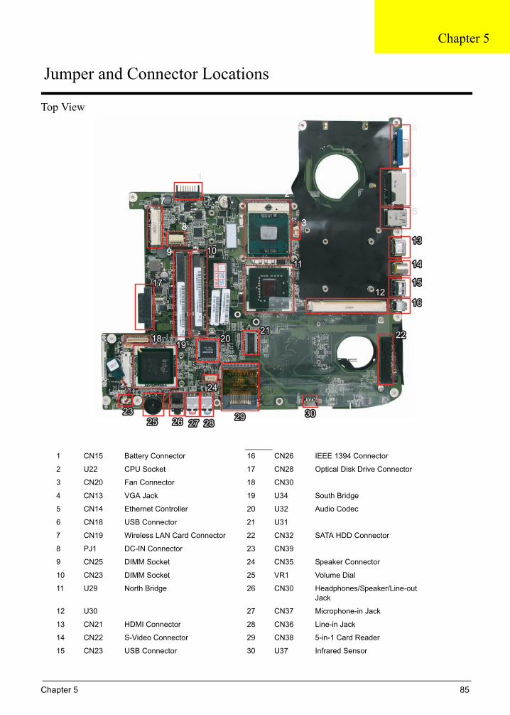
Board Layout
Top View
1 CN15 Battery Connector 16 CN26 IEEE 1394 Connector
2 U22 CPU Socket 17 CN28 Optical Disk Drive Connector
3 CN20 Fan Connector 18 CN30
4 CN13 VGA Jack 19 U34 South Bridge
5 CN14 Ethernet Controller 20 U32 Audio Codec
6 CN18 USB Connector 21 U31
7 CN19 Wireless LAN Card Connector 22 CN32 SATA HDD Connector
8 PJ1 DC-IN Connector 23 CN39
9 CN25 DIMM Socket 24 CN35 Speaker Connector
10 CN23 DIMM Socket 25 VR1 Volume Dial
11 U29 North Bridge 26 CN30 Headphones/Speaker/Line-out Jack
12 U30 27 CN37 Microphone-in Jack
13 CN21 HDMI Connector 28 CN36 Line-in Jack
14 CN22 S-Video Connector 29 CN38 5-in-1 Card Reader
15 CN23 USB Connector 30 U37 Infrared Sensor
11
2
3
4
2
3
4
5
7
8
9
6
5
7
8
9 1010
1414
1212
1313
1515
1616
1111
10
14
12
13
15
16
1717
18181919
2020 2222
17
1819
20 22
232323
242424
2525 2626 2727 28282929 3030
25 26 27 2829 30
212121
11
6
6 Chapter 1
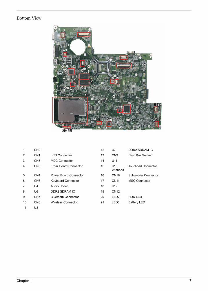
Bottom View
1 CN2 12 U7 DDR2 SDRAM IC
2 CN1 LCD Connector 13 CN9 Card Bus Socket
3 CN3 MDC Connector 14 U11
4 CN5 Email Board Connector 15 U10 Winbond
Touchpad Connector
5 CN4 Power Board Connector 16 CN16 Subwoofer Connector
6 CN6 Keyboard Connector 17 CN11 MSC Connector
7 U4 Audio Codec 18 U19
8 U6 DDR2 SDRAM IC 19 CN12
9 CN7 Bluetooth Connector 20 LED2 HDD LED
10 CN8 Wireless Connector 21 LED3 Battery LED
11 U8
11 2
3
4
2
3
4
5
7
8
9
6
5
7
8
9 1010
1414
1212
1313
15151616
111110
14
12
13
1516
1717 1818 191917 18 19
11
6
202020 212121
Chapter 1 7

Your Acer Notebook tourAfter knowing your computer features, let us show you around your new Aspire computer.
Front View
# Icon Item Description
1 Built-in camera 0.3 megapixel web camera for video communication.
2 Microphone Internal microphone for sound recording.
3 Power button Turns the computer on and off.
4 Speaker Left and right speakers deliver stereo audio output.
8 Chapter 1

Closed Front View
5 Wireless communication button/indicator
Enables/disables the wireless function. Indicates the status of wireless LAN communication.
6 WWW/E-mail buttons Button to launch your internet browser and e-mail reader.
7 Bluetooth® communication button/indicator
Enables/disables the Bluetooth® function. Indicates the status of Bluetooth communication.
8 Keyboard For entering data into your computer.
9 Touchpad Touch-sensitive pointing device which functions like a computer mouse.
10 4-way scroll button To scroll up, down, left, and right.
11 Status indicators Light-Emitting Diodes (LEDs) that light up to show the status of the computer’s functions and components.
12 Click buttons (left and right)
The left and right buttons function like the left and right mouse buttons.
13 Display screen Also called Liquid-Crystal Display (LCD), displays computer output.
14 Empowering button Launches the Empowering Technology toolbar.
15 Media buttons To play, pause, record, rewind, fast forward or stop playback / recording.
16 Palmrest Comfortable support area for your hands when you use the computer.
# Icon Item Description
1 Power indicator Indicates the computer’s power status.
2 Battery indicator Indicates the computer’s battery status.
3 Infrared port Interfaces with infrared devices (e.g, infrared printer and IR-aware computer).
4 5-in-1 card reader Accepts Secure Digital (SD), MultiMediaCard (MMC), Memory Stick (MS), Memory Stick PRO (MS PRO), xD-Picture Card (xD).
# Icon Item Description
Note:
Chapter 1 9

"Easy-launch buttons" on page 18
# Icon Item Description
# Item Description
"Easy-launch buttons" on page 18
# Icon Item Description
# Item Description
Left View
5 Line-in jack Accepts audio line-in devices (e.g., audio CD player, stereo walkman).
6 Microphone-in jack Accepts input from external microphones.
7 Headphones/speaker/line-out jack with S/PDIF support
Connects to audio line-out devices (e.g., speakers, headphones).
8 Volume control Increases and decreases the volume.
# Icon Item Description
1 External display (VGA) port
Connects to a display device (e.g., external monitor, LCD projector).
2 Ethernet (RJ-45) Connects to an Ethernet 10/100/1000-based network (for selected models).
3 Modem (RJ-11) port Connects to a phone line.
4 2 USB 2.0 ports Connect to USB 2.0 devices (e.g., USB mouse, USB camera).
5 HDMI port Connects to a television or display device with HDMI input.
6 S-video/TV-out (NTSC/PAL) port
Connects to a television or display device with S-video input.
7 USB 2.0 port Connect to USB 2.0 devices (e.g., USB mouse, USB camera).
8 4-pin IEEE 1394 port Connects to IEEE 1394 devices.
9 PC Card slot Accepts one Type II PC Card.
10 Chapter 1

Right View
Rear view
# Icon Item Description
1 Optical drive Internal optical drive; accepts CDs or DVDs (slot-load or tray-load depending on model).
2 Optical disk access indicator
Lights up when the optical drive is active.
3 Optical drive eject button
Ejects the optical disk from the drive.
4 Emergency eject hole Ejects the optical drive tray when the computer is turned off.
5 USB 2.0 port Connect to USB 2.0 devices (e.g., USB mouse, USB camera).
6 Kensington lock slot Connects to a Kensington-compatible computer security lock.
# Icon Item Description
1 DC-in jack Connects to an AC adapter.
Chapter 1 11

Base view
IndicatorsThe computer has several easy-to-read status indicators.
The front panel indicators are visible even when the computer cover is closed up.
# Item Description
1 Battery bay Houses the computer’s battery pack.
2 Battery lock Locks the battery in position.
3 Battery release latch Releases the battery for removal.
4 Ventilation slots and cooling fan
Enable the computer to stay cool, even after prolonged use.Note: Do not cover or obstruct the opening of the fan.
5 System fan Enables the motheboard to stay cool, even after prolonged use.Note: Do not cover or obstruct the opening of the fan.
6 Memory compartment Houses the computer’s main memory.
7 Hard disk bay Houses the computer’s hard disk (secured with screws)
12 Chapter 1

Icon Function Description
NOTE: 1. Charging: The light shows amber when the battery is charging. 2. Fully charged: The light shows green when in AC mode.
Easy-Launch ButtonsTo the right of the keyboard there are three easy-launch buttons: Web browser, mail, and one user-
programmable button. You can also find an Empowering Key “ located above the keyboard.
Press “ “ to run the Acer Empowering Technology. The mail and Web browser buttons are pre-set to email and Internet programs, but can be reset by users. To set the Web browser, mail and programmable buttons, run the Acer Launch Manager.
Icon Function Description
HDD Indicates when the hard disc or optical drive is active.
Num lock Lights when Num Lock is activated.
Cap lock Lights when Cap Lock is activated
Power Lights up when the computer is on.
Battery Lights up when the battery is being charged.
Bluetooth Indicates the status of Bluetooth communication.
Wireless LAN Indicates the status of wireless LAN communication.
Chapter 1 13

Touchpad BasicsThe following teaches you how to use the touchpad:
Move your finger across the touchpad (2) to move the cursor.
Press the left (1) and right (4) buttons located beneath the touchpad to perform selection and execution functions. These two buttons are similar to the left and right buttons on a mouse. Tapping on the touchpad is the same as clicking the left button.
Use the fingerprinter (3) to enroll the computer with registered fingerprint. This recognition device helps prevent unauthorized access by others.
NOTE: When using the touchpad, keep it - and your fingers - dry and clean. The touchpad is sensitive to finger movements; hence, the lighter the touch, the better the response. Tapping too hard will not increase the touchpad’s responsiveness.
Launch key Default application
Acer Empowering Technology (user-programmable)
Web browser Internet browser (user-programmable)
Mail Email application (user-programmable)
P User-programmable
Function Left Button (1) Right Button (4) Main touchpad (2) Fingerprinter (3)
Execute Click twice quickly Tap twice (at the same speed as double-clicking the mouse button)
Select Click once Tap once
Drag Click and hold, then use finger on the touchpad to drag the cursor.
Tap twice (at the same speed as double-clicking a mouse button); rest your finger on the touchpad on the second tap and drag the cursor.
Access context menu
Click once
Log in with authorized fingerprint
Swipe your finger over the fingerprinter.
14 Chapter 1

Using the KeyboardThe keyboard has full-sized keys and an embedded keypad, separate cursor keys, one Windows key and twelve function keys.
Lock Keys and embedded numeric keypadThe keyboard has three lock keys which you can toggle on and off.
The embedded numeric keypad functions like a desktop numeric keypad. It is indicated by small characters located on the upper right corner of the keycaps. To simplify the keyboard legend, cursor-control key symbols are not printed on the keys.
Windows KeysThe keyboard has one key that performs Windows-specific functions.
Lock Key Description
Caps Lock When Caps Lock is on, all alphabetic characters typed are in uppercase.
Num lock <Fn>+<F11>
When Num Lock is on, the embedded keypad is in numeric mode. The keys function as a calculator (complete with the arithmetic operators +, -, *, and /). Use this mode when you need to do a lot of numeric data entry. A better solution would be to connect an external keypad.
Scroll lock <Fn>+<F12>
When Scroll Lock is on, the screen moves one line up or down when you press the up or down arrow keys respectively. Scroll Lock does not work with some applications.
Desired Access Num Lock On Num Lock Off
Number keys on embedded keypad
Type numbers in a normal manner.
Cursor-control keys on embedded keypad
Hold <Shift> while using cursor-control keys.
Hold <Fn> while using cursor-control keys.
Main keyboard keys Hold <Fn> while typing letters on embedded keypad.
Type the letters in a normal manner.
Chapter 1 15

Hot KeysThe computer employs hotkeys or key combinations to access most of the computer’s controls like screen brightness, volume output, and the BIOS utility.
To activate hot keys, press and hold the <Fn> key before pressing the other key in the hotkey combination.
Key Icon Description
Windows key Pressed alone, this key has the same effect as clicking on the Windows Start button; it launches the Start menu. It can also be used with other keys to provide a variety of function:
+ <Tab> Activates next taskbar button.
+ <E> Opens the My Computer window
+ <F1> Opens Help and Support.
+ <F> Opens the Search: All Files dialog box.
+ <R> Opens the Run dialog box.
+ <M> Minimizes all windows.
<Shift>+ + <M> Undoes the minimize all windows action.
Application keyThis key has the same effect as clicking the right mouse button; it opens the application’s context menu.
Hot Key Icon Function Description
<Fn>+<F1> Hot key help Displays help on hot keys.
<Fn>+<F2> Acer eSettings Launches the Acer eSettings in Acer eManager.
<Fn>+<F3> Acer ePower Management
Launches the Acer ePower Management in Acer Empowering Technology. See “Acer Empowering Technology” on page 18.
<Fn>+<F4> Sleep Puts the computer in Sleep mode.
16 Chapter 1
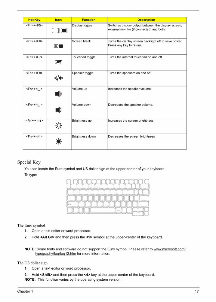
Special KeyYou can locate the Euro symbol and US dollar sign at the upper-center of your keyboard.
To type:
The Euro symbol1. Open a text editor or word processor.
2. Hold <Alt Gr> and then press the <5> symbol at the upper-center of the keyboard.
NOTE: Some fonts and software do not support the Euro symbol. Please refer to www.microsoft.com/typography/faq/faq12.htm for more information.
The US dollar sign1. Open a text editor or word processor.
2. Hold <Shift> and then press the <4> key at the upper-center of the keyboard.NOTE: This function varies by the operating system version.
<Fn>+<F5> Display toggle Switches display output between the display screen, external monitor (if connected) and both.
<Fn>+<F6> Screen blank Turns the display screen backlight off to save power. Press any key to return.
<Fn>+<F7> Touchpad toggle Turns the internal touchpad on and off.
<Fn>+<F8> Speaker toggle Turns the speakers on and off.
<Fn>+<w> Volume up Increases the speaker volume.
<Fn>+<y> Volume down Decreases the speaker volume.
<Fn>+<-x> Brightness up Increases the screen brightness.
<Fn>+<z> Brightness down Decreases the screen brightness
Hot Key Icon Function Description
Gr
Chapter 1 17

Acer Empowering TechnologyAcer’s innovative Empowering Technology makes it easy for you to access frequently used functions and manage your new Acer notebook. It features the following handy utilities:
Acer eNet Management hooks up to location-based networks intelligently.Acer ePower Management extends battery power via versatile usage profiles.Acer ePresentation Management connects to a projector and adjusts display settings conveniently.Acer eDataSecurity Management protects data with passwords and advanced encryption algorithms.Acer eLock Management limits access to external storage media.Acer eRecovery Management backs up and recovers data flexibly, reliably and completely.Acer eSettings Management accesses system information and adjusts settings easily.Acer ePerformance Management improves system performance by optimizing disk space, memory and registry settings.
For more information, press the < > key to launch the Empowering Technology toolbar, then click on the appropriate utility and select the Help or Tutorial function.
Empowering Technology passwordBefore using Acer eLock Management and Acer eRecovery Management, you must initialize the Empowering Technology password. Right-click on the Empowering Technology toolbar and select “Password Setup” to do so. If you do not initialize the Empowering Technology password, you will be prompted to do so when running Acer eLock Management or Acer eRecovery Management for the first time.
Acer eNet Management Acer eNet Management helps you to quickly and easily connect to both wired and wireless networks in a variety of locations. To access this utility, either click on the “Acer eNet Management” icon on your notebook, or start the program from the Start menu. You also have the option to set Acer eNet Management to start automatically when you boot up your PC.
Acer eNet Management automatically detects the best settings for a new location, while offering you the freedom to manually adjust the settings to match your needs.
18 Chapter 1

Acer eNet Management can save network settings for a location to a profile, and automatically switch to the appropriate profile when you move from one location to another. Settings stored include network connection settings (IP and DNS settings, wireless AP details, etc.), as well as default printer settings.
Security and safety concerns mean that Acer eNet Management does not store username and password information.
Chapter 1 19

Acer ePower Management Acer ePower Management features a straightforward user interface. To launch it, select Acer ePower Management from the Empowering Technology interface.
AC Mode (Adapter mode)The default setting is “Maximum Performance.” You can adjust CPU speed, LCD brightness and other settings, or click on buttons to turn the following functions on/off: Wireless LAN, Bluetooth, CardBus, FireWire (1394), Wired LAN and Optical Device if supported.
DC Mode (Battery mode)There are three pre-defined profiles - Balanced, Power Saver, and High Performance. You can also define the power plan optimized for your needs.
To create new power plan1. Select a predefined power plan and click the “ “ icon shown on the lower left-hand side.
2. Enter the name for the newly created power plan.
3. Select one of the predefined power plan that is closest to what you want.
4. Change the display and sleep settings as desired.
5. Click “OK“ to apply the setting.
6. A new power plan is created.
20 Chapter 1

Battery statusFor real-time battery life estimates based on current usage, refer to the time shown in the “Remaining Battery Life” field.
For additional power options, click “More Power option”.
Acer ePresentation Management Acer ePresentation Management lets you project your computer’s display to an external device or project using the hot key: Fn + F5. If auto-detection hardware is implemented in the system, your system display will be automatically switched out when an external display is connected to the system.
Chapter 1 21

Acer eDataSecurity Management Acer eDataSecurity Management is handy file encryption utility that protects your files from being accessed by unauthorized persons. It is conveniently integrated with Windows explorer as a shell extension for quick and easy data encryption/decryption and also supports on-the-fly file encryption for MSN Messenger and Microsoft Outlook.
The Acer eDataSecurity Management setup wizard will prompt you for a supervisor password and default encryption. This encryption will be used to encrypt files by default, or you can choose to enter your won file-specific password when encrypting a file.
NOTE: The password used encrypt a file is the unique key that the system needs to decrypt it. If you lose the password, the supervisor password is the only other key capable of decrypting the file. If you lose both passwords, there will be no way to decrypt your encrypted file! Be sure to safeguard all related passwords!
22 Chapter 1

Chapter 1 23

Acer eLock Management Acer eLock Management is a security utility that allows you to lock your removable data, optical and floppy drives to ensure that data cannot be stolen while your notebook is unattended.
Removable data devices - includes USB disk drives, USB pen drives, USB flash drives, USB MP3 drives, USB memory card readers, IEEE 1394 disk drives and any other removable disk drives that can be mounted as a file system when plugged into the system.Optical drive devices - includes any kind of CD-ROM or DVD-ROM drives.Floppy disk drives - 3.5-inch disks only.Interfaces - includes serial ports, parallel port, infrared (IR), and Bluetooth.
To activate Acer eLock Management, a password must be set first. Once set, you can apply locks to any of the devices. Lock(s) will immediately be set without any reboot necessary, and will remain locked after rebooting, until unlocked.
NOTE: If you lose your password, there is no method to reset it except by reformatting your notebook or taking your notebook to an Acer Customer Service Center. Be sure to remember or write down your password.
24 Chapter 1

Acer eRecovery Management Acer eRecovery Management is a powerful utility that does away with the need for recovery disks provided by the manufacturer. The Acer eRecovery Management utility occupies space in a hidden partition on your system’s HDD. User-created backups are stored on D:\ drive. Acer eRecovery Management provides you with:
Password protection.Recovery of applications and drivers.Image/data backup:
Back up to HDD (set recovery point).
Back up to CD/DVD.Image/data recovery tools:
Recover from a hidden partition (factory defaults).
Recover from the HDD (most recent user-defined recovery point).
Recover from CD/DVD.
For more information, please refer to “Acer eRecovery Management”
NOTE: If your computer did not come with a Recovery CD or System CD, please use Acer eRecovery Management’s “System backup to optical disk” feature to burn a backup image to CD or DVD. To ensure the best results when recovering your system using a CD or Acer eRecovery Management, detach all peripherals (except the external Acer ODD, if your computer has one), including your Acer ezDock.
Chapter 1 25

Acer eSettings Management Acer eSettings Management allows you to inspect hardware specifications and to monitor the system health status. Furthermore, Acer eSettings Management enables you to optimize your Windows operating system, so your computer runs faster, smoother and better.
Acer eSettings Management also:
Provides a simple graphical user interface for navigating.Displays general system status and advanced monitoring for power users.
Getting to know your Acer OrbiCam
1 2 33
26 Chapter 1

Launching the Acer OrbiCamTo launch the Acer OrbiCam, double click on the Acer OrbiCam icon on the screen.
OR
Click Start > All programs > Acer > Acer OrbiCam. The Acer OrbiCam capture window appears.
Changing the Acer OrbiCam resolutionTo change the capture resolution, click the displayed resolution button to select the desired resolution.
Using the Acer OrbiCam as webcamThe Acer OrbiCam is automatically selected as the capture device of any instant messenger (IM) application. To use the Acer OrbiCam as a webcam, open the IM service, then select the video/webcam feature. You can now broadcast from your location to an IM partner anywhere in the world.
No. Item1 Lens
2 Power indicator
3 Rubber grip (selected models only)
Chapter 1 27

Note:
Using the System UtilitiesNOTE: The system utilities work under Microsoft Windows XP only.
Acer GridVista (dual-display compatible)NOTE: This feature is only available on certain models.
To enable the dual monitor feature of the notebook, first ensure that the second monitor is connected, then select Start, Control Panel, Display and click on Settings. Select the secondary monitor (2) icon in the display box and then click the check box Extend my windows desktop onto this monitor. Finally, click Apply to confirm the new settings and click OK to complete the process.
Acer GridVista is a handy utility that offers four pre-defined display settings so you can view multiple windows on the same screen. To access this function, please go to Start > All Programs and click on Acer GridVista. You may choose any one of the four display settings indicated below:
Double (vertical), Triple (primary at left), Triple (primary at right), or Quad Acer Gridvista is dual-display compatible, allowing two displays to be partitioned independently.
Acer Gridvista is dual-display compatible, allowing two displays to be partitioned independently.
AcerGridVista is simple to set up:
1. Run Acer GridVista and select your preferred screen configuration for each display from the task bar.
2. Drag and drop each window into the appropriate grid.
3. Enjoy the convenience of a well-organized desktop.
Start Control Panel Display
Settings (2)
Extend my windows desktop onto this monitor
Apply OK
Start All Programs Acer GridVista
Note:
Start Control Panel Display
Settings (2)
Extend my windows desktop onto this monitor
Apply OK
Start All Programs Acer GridVista
28 Chapter 1
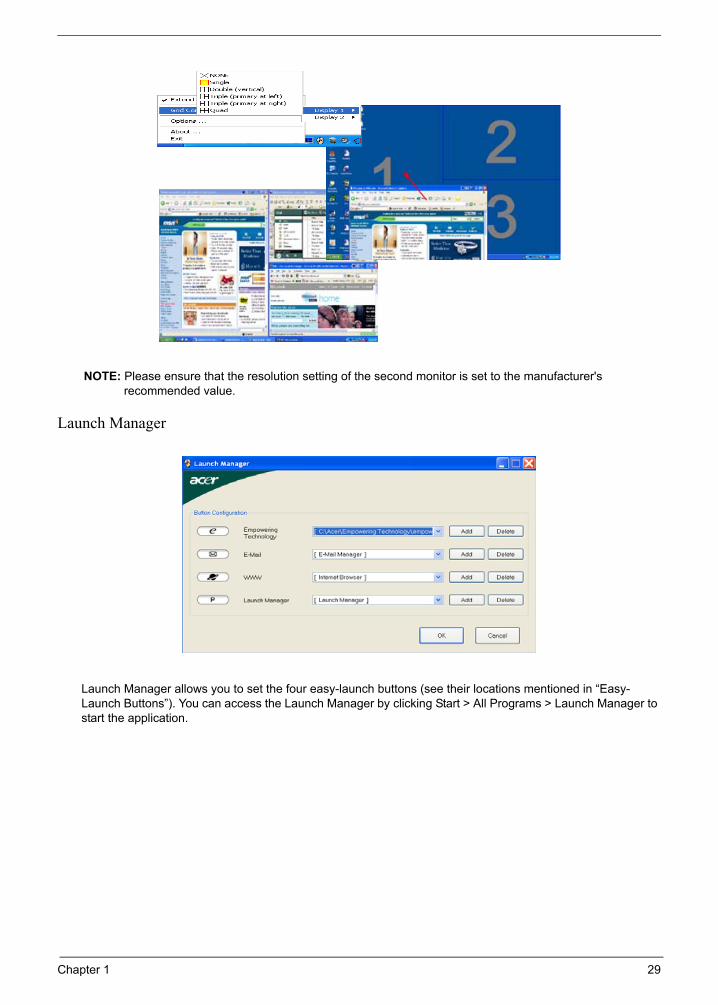
NOTE: Please ensure that the resolution setting of the second monitor is set to the manufacturer's recommended value.
Launch Manager
Launch Manager allows you to set the four easy-launch buttons (see their locations mentioned in “Easy-Launch Buttons”). You can access the Launch Manager by clicking Start > All Programs > Launch Manager to start the application.
Note:
"Easy-launch buttons" on page 24
Start All Programs
Launch Manager
Note:
"Easy-launch buttons" on page 24
Start All Programs
Launch Manager
Chapter 1 29

Hardware Specifications and Configurations
NOTE: If you need to check PXE version, press F2 to enter BIOS then enable boot from LAN function. After that, power off the system and remove the HDD. Last, reboot the laptop. Then you will see PXE version displaying on the screen.
Processor
Item Specification
CPU type Intel® CoreTM Duo processor (4 MB L2 cache, 1.66/1.83/2/2.16 GHz, 800 MHz FSB) or higher
Core logic Intel® PM965 Chipset
CPU package Intel 479 pin Micro-FCPGA
CPU core voltage 0.725~1.25V
CPU Fan True Value Table
TEST Condition: 35W@Ambient 35 degree C
CPU Temperature Fan Speed Acoustic Level
Core 0 Core 1 (rpm) (dBA)
86 86 3700 39
88 88 3450 36.5
91 91 3150 34.5
95 95 2800 31
BIOS
Item Specification
BIOS vendor Phoenix
BIOS Version
BIOS ROM type Flash ROM
BIOS ROM size 1MB
BIOS package 8 pin SOIC
Supported protocols ACPI 1.0b/2.0/3.0, PCI 2.2, System/HDD Password Security Control, INT 13h Extensions, PnP BIOS 1.0a, SMBIOS 2.4, Simple Boot Flag 1.0, Boot Block, PCI Bus Power Management Interface Specification, USB1.1/2.0, IEEE 1394 1.0, USB/1394 CD-ROM Boot Up support, PC Card 95 (PCMCIA 3.0 Compliant Device), IrDA 1.0, Intel AC97 CNR Specification, WfM 2.0, PXE (Preboot Execution Environment), BIS 1.0 (Boot Integrity Service Application Program Interface), PC99a and Mobile PC2001 Compliant, Intel Enhanced SpeedStep Technology
BIOS password control Set by setup manual
Second Level Cache
Item Specification
Cache controller Built-in CPU
Cache size 4MB
1st level cache control Always enabled
2st level cache control Always enabled
Cache scheme control Fixed in write-back
30 Chapter 1

NOTE: Above table lists some system memory configurations. You may combine DIMMs with various capacities to form other combinations. On above table, the configuration of slot 1 and slot 2 could be reversed.
System Memory
Item Specification
Memory controller Built-in Intel® PM965
Memory size 0MB (no on-board memory)
DIMM socket number 2 sockets
Supports memory size per socket 2GB
Supports maximum memory size 4GB (by two 1024MB SO-DIMM module)
Supports DIMM type DDR 2 Synchronous DRAM
Supports DIMM Speed 533/667 MHz
Supports DIMM voltage 1.8V and 0.9V
Supports DIMM package 200-pin soDIMM
Memory module combinations You can install memory modules in any combinations as long as they match the above specifications.
Memory Combinations
Slot 1 Slot 2 Total Memory
0MB 128MB 128MB
0MB 256MB 256MB
0MB 512MB 512MB
0MB 1024MB 1024MB
0MB 2048MB 2048MB
128MB 128MB 256MB
128MB 256MB 384MB
128MB 512MB 640MB
128MB 1024MB 1152MB
128MB 2048MB 2176MB
256MB 128MB 384MB
256MB 256MB 512MB
256MB 512MB 768MB
256MB 1024MB 1280MB
256MB 2048MB 2304MB
512MB 128MB 640MB
512MB 256MB 768MB
512MB 512MB 1024MB
512MB 1024MB 1536MB
512MB 2048MB 2560MB
1024MB 0MB 1024MB
1024MB 128MB 1152MB
1024MB 256MB 1280MB
1024MB 512MB 1536MB
1024MB 1024MB 2048MB
1024MB 2048MB 3072MB
2048MB 2048MB 4096MB
Chapter 1 31

LAN Interface
Item Specification
Chipset Broadcom 5787M
Supports LAN protocol 10/100/1000 EthernetGiga LAN
LAN connector type RJ45
LAN connector location Left side
Features Integrated 10/100/1000 BASE-T transceiverWake on LAN support compliant with ACPI 2.0PCI v1.168pin-QFN package
Modem Interface
Item Specification
Data modem data baud rate (bps) 56K
Supports modem protocol V.92
Modem connector type RJ11
Modem connector location Right side
Bluetooth Interface
Item Specification
Chipset FOXCON T60H928.01 Bluetooth miniUSB module
Data throughput 723 bps (full speed data rate)
Protocol Bluetooth 2.0+EDR
Interface USB 1.1
Connector type USB
Wireless Module 802.11a/b/g/n
Item Specification
Chipset Kedron-n 3945abg
Data throughput 11~54 Mbps
Protocol 802.11b/g & abgn
Interface PCI
Hard Disk Drive Interface
Item
Vendor & Model Name
Seagate 40G ST9402112AToshiba MK4025GAS Hitachi HTS421240H9AT00WD WD400UE-22HCT0Samsung M40MP0402H
Seagate ST96812ASeagate ST960821AToshiba MK6025GASHGST HTS541260H9AT00WD WD600UE-22HCT0
TOSHIBA MK8025GAS HITACHI HTS421280H9AT00SEAGATE ST9808210ASEAGATE ST98823ATOSHIBA MK8026GAXHGST HTS541280H9AT00WD WD800UE-22HCT0
Capacity (MB) 40000 60000 80000
Bytes per sector
512 512 512
Data heads 2 3 (for Hitachi and Seagate)4 (for Toshiba)
4 (for Hitachi)3 (for Seagate)
32 Chapter 1

Drive Format
Disks 1 2 2
Spindle speed (RPM)
4200 RPM 4200 RPM 4200 RPM
Performance Specifications
Buffer size 2048KB 8192KB 8192KB
Interface ATA/ATAPI-6; ATA-6 ATA/ATAPI-6; ATA-6 ATA/ATA-6; ATA-6
Max. media transfer rate (disk-buffer, Mbytes/s)
372 350 350
Data transfer rate (host~buffer, Mbytes/s)
100 MB/Sec.Ultra DMA mode-5
100 MB/Sec.Ultra DMA mode-5
100 MB/Sec.Ultra DMA mode-5
DC Power Requirements
Voltage tolerance
5V(DC) +/- 5% 5V(DC) +/- 5% 5V(DC) +/- 5%
DVD-Dual Interface
Item Specification
Vendor & model name LITEON SOSW-833SPIONEER DVR-K16RA
Performance Specification With CD Diskette With DVD Diskette
Transfer rate (KB/sec) Sustained:Max 3.6Mbytes/sec
Sustained:Max 10.8Mbytes/sec
Buffer Memory 2MB
Interface Enhanced IDE(ATAPI) compatible
Applicable disc format Support disc formats1. Reads data in each CD-ROM, CD-ROM XA, CD-1, Video CD, CD-Extra and CD-Text2. Reads data in Photo CD (single and Multi-session)3. Reads standard CD-DA4. Reads and writes CD-R discs5. Reads and writes CD-RW discs6. Reads and writes in each DVD+R/RW (Ver. 1.1)7. Reads data in each DVD-ROM and DVD-R (Ver. 2.0 for Authoring)8. Reads and writes in each DVD-R (Ver. 2.0 for general), DVD-RW and DVD+R/RW (Ver1.1)
Loading mechanism Load: ManualRelease: (a) Electrical Release (Release Button) (b) Release by ATAPI command (c) Emergency Release
Power Requirement
Input Voltage 5 V +/- 5 % (Operating)
Audio Interface
Item Specification
Audio Controller Realtek ALC888S
Audio onboard or optional Built-in
Hard Disk Drive Interface
Item
Chapter 1 33

Mono or Stereo Stereo
Resolution 18 bit stereo full duplex
Compatibility HD audio Interface; S/PDIF output for PCM or AC-3 content
Sampling rate 44.1k/48k/96k/192kHZ sample rate
Internal microphone Yes
Internal speaker / Quantity Yes/2(1.5W speakers)
Supports PnP DMA channel DMA channel 0DMA channel 1
Supports PnP IRQ IRQ10, IRQ11
USB Port
Item Specification
Chipset Built-in ICH8M
USB Compliancy Level 2.0
OHCI USB 1.1 and USB 2.0 Host controller
Number of USB port 4
Location One on the left side; three on the rear side
Serial port function control Enable/Disable by BIOS Setup
PCMCIA Port
Item Specification
PCMCIA controller TI PCI 7412
Supports card type Type-II
Number of slots One type-II
Access location Left side
Supports ZV (Zoomed Video) port No ZV support
Supports 32 bit CardBus Yes
System Board Major Chips
Item Controller
Core logic IIntel® PM965 Chipset
LAN Broadcom 5787M
USB 2.0 Built in ICH8M
Super I/O controller NS 87383
MODEM Built-in ICH7-M
Bluetooth Built-in ICH7-M
Wireless 802.11 a+b+g+n Kedron-n 3945
PCMCIA TI PCI 7412
Audio Realtek ALC888S
Keyboard
Item Specification
Keyboard controller KBC8769LDG
Audio Interface
Item Specification
34 Chapter 1

Total number of keypads 88-/89-key
Windows logo key Yes
Internal & external keyboard work simultaneously
Plug USB keyboard to the USB port directly: Yes
Battery
Item Specification
Vendor & model name BATTERY PACK SANYO LI-ION 8 CELL2.4, 4800MAHBATTERY PACK SONY LI-ION 8CELL2.4, 4800MAHBATTERY PACK SIMPLO LI-ION 8 CELL2.4, 4800MAHBATTERY PACK PANASONICLI-ION 8 CELL2.4, 4800MAH
Battery Type Li-ion
Pack capacity 4000mAH/4800 mAH
Number of battery cell 8
Package configuration 4 cells in series, 2 series in parallel
Normal voltage 11.1V
Charge voltage 16.8+-0.2v
LCD 15.4” inch
Item Specification
Vendor & model name SAMSUNG LTN190-M2-000 NON-GLARE
CMO M190A1-L01 NON-GLARE
SAMSUNG LTM190-M2-L01-G GLARE TYPE
CMO M190A1-L03 GLARE TYPE
Screen Diagonal (mm) 19.1 inches 19.1 inches 19.1 inches 19.1 inches
Active Area (mm) 304.1x228.1 304.1x228.1 304.1x228.1
Display resolution (pixels) 1440x900 WXGA+
1440x900 WXGA+
1440x900 WXGA+
1440x900 WXGA+
Pixel Pitch 0.297x0.297 0.099x0.297 0.297x0.297
Pixel Arrangement R.G.B. Vertical Stripe
R.G.B. Vertical Stripe
R.G.B. Vertical Stripe
R.G.B. Vertical Stripe
Display Mode Normally White Normally White Normally White Normally White
Typical White Luminance (cd/m2)also called Brightness
300 300 300 300
Luminance Uniformity N/A N/A 70 70
Contrast Ratio 300 300 250 250
Response Time (Optical Rise Time/Fall Time)msec
8 8 8 8
Nominal Input Voltage VDD +3.3V Typ. +3.3V 3.3V 3.3V
Typical Power Consumption (watt) 5.6/5.7 3.96 N/A N/A
Weight 550 570 600 600
Physical Size(mm) 317.3x242.0x6.0
317.3x242.0x5.9
317.3x242.0x6.5
317.3x242.0x6.5
Electrical Interface 1 channel LVDS 1 channel LVDS 1 channel LVDS 1 channel LVDS
Keyboard
Item Specification
Chapter 1 35

Support Color 262K colors (RGB 6-bit data driver)
262,144 262,144 262,144
Viewing Angle (degree)Horizontal: Right/LeftVertical: Upper/Lower
40/4010/30
45/4515/35
40/4020/40
40/4020/40
Temperature Range( C)
OperatingStorage (shipping)
0 to +50-20 to +60
0 to +50-25 to +60
0 to +50-20 to +60
0 to +50-20 to +60
LCD Inverter
Item Specification
Vendor & model name Darfon/V189-301GP
Brightness conditions N/A
Input voltage (V) 9~21
Input current (mA) 2.56 (max)
Output voltage (V, rms) 780V (2000V for kick off)
Output current (mA, rms) 6.5 (max)
Output voltage frequency (k Hz) 65K Hz (max)
AC Adaptor
Item Specification
Input rating 90V AC to 264V AC, 47Hz to 63Hz
Maximum input AC current 1.7A
Inrush current 220A@115VAC220A@230VAC
Efficiency 82% min. @115VAC input full load
System Power Management
ACPI mode Power Management
Mech. Off (G3) All devices in the system are turned off completely.
Soft Off (G2/S5) OS initiated shutdown. All devices in the system are turned off completely.
Working (G0/S0) Individual devices such as the CPU and hard disc may be power managed in this state.
Suspend to RAM (S3) CPU set power downVGA SuspendPCMCIA SuspendAudio Power DownHard Disk Power DownCD-ROM Power DownSuper I/O Low Power mode
Save to Disk (S4) Also called Hibernation Mode. System saves all system states and data onto the disc prior to power off the whole system.
LCD 15.4” inch
Item Specification
°
36 Chapter 1

System Utilities
Chapter 2
BIOS Setup UtilityThe BIOS Setup Utility is a hardware configuration program built into your computer’s BIOS (Basic Input/Output System).
Your computer is already properly configured and optimized, and you do not need to run this utility. However, if you encounter configuration problems, you may need to run Setup. Please also refer to Chapter 4 Troubleshooting when problem arises.
To activate the BIOS Utility, press m during POST (when “Press <F2> to enter Setup” message is prompted on the bottom of screen).
Press m to enter setup. The default parameter of F12 Boot Menu is set to “disabled”. If you want to change boot device without entering BIOS Setup Utility, please set the parameter to “enabled”.
Press <F12> during POST to enter multi-boot menu. In this menu, user can change boot device without entering BIOS SETUP Utility.
Phoenix TrustedCore(tm) Setup Utility
CPU Type : Intel (R) Core(TM)2 Duo CPU T7300 @ 2.00GHz
CPU Speed :
System BIOS Version: v0.2412
VGA BIOS Version: nVidia 0.84.41.00.08
Serial Number: xxxxxxxxxxxxxxxxxxxxxx
Asset Tag Number:
Produce Name:
Manufacturer Name: Acer
UUID: xxxxxxxxxxxxxxxxxxxxxxxxxxxxxxxx
F1 Help Select Item F5/F6 Change Values F9 Setup Defaults
Esc Exit Select Menu Enter Select Sub-Menu F10 Save and Exit
IDE1 Model Name : ST980811AS
ATAPI Model Name : Optiarc DVD RW AD-7530A
IDE1 Serial Number : xxxxxxxxxxxxxxxxxxxxxx
2000 MHz
Main Security Boot Exit Information
Chapter 2 37

Navigating the BIOS UtilityThere are six menu options: Info., Main, System Devices, Security, Boot, and Exit.
Follow these instructions:
To choose a menu, use the cursor left/right keys (zx).
To choose a parameter, use the cursor up/down keys (wy).
To change the value of a parameter, press por q.
A plus sign (+) indicates the item has sub-items. Press e to expand this item.
Press ^ while you are in any of the menu options to go to the Exit menu.
In any menu, you can load default settings by pressing t. You can also press u to save any changes made and exit the BIOS Setup Utility.
NOTE: You can change the value of a parameter if it is enclosed in square brackets. Navigation keys for a particular menu are shown on the bottom of the screen. Help for parameters are found in the Item Specific Help part of the screen. Read this carefully when making changes to parameter values. Please note that system information is subject to different models.
38 Chapter 2

Information
NOTE: The system information is subject to different models.
Parameter Description
CPU Type / CPU Speed This field shows the CPU type and speed of the system.
IDE1 Model Name This field shows the model name of HDD installed on primary IDE master.
IDE1 Serial Number This field displays the serial number of HDD installed on primary IDE master.
ATAPI Model Name This field displays the model number of the installed ATAPI drive.
System BIOS Version Displays system BIOS version.
VGA BIOS Version This field displays the VGA firmware version of the system.
Serial Number This field displays the serial number of this unit.
Asset Tag Number This field displays the asset tag number of the system.
Product Name This field shows product name of the system.
Manufacturer Name This field displays the manufacturer of this system.
UUID Number This will be visible only when an internal LAN device is presenting.UUID=32bytes
Phoenix TrustedCore(tm) Setup Utility
CPU Type : Intel (R) Core(TM)2 Duo CPU T7300 @ 2.00GHz
CPU Speed :
System BIOS Version: v0.2412
VGA BIOS Version: nVidia 0.84.41.00.08
Serial Number: xxxxxxxxxxxxxxxxxxxxxx
Asset Tag Number:
Produce Name:
Manufacturer Name: Acer
UUID: xxxxxxxxxxxxxxxxxxxxxxxxxxxxxxxx
F1 Help Select Item F5/F6 Change Values F9 Setup Defaults
Esc Exit Select Menu Enter Select Sub-Menu F10 Save and Exit
IDE1 Model Name : ST980811AS
ATAPI Model Name : Optiarc DVD RW AD-7530A
IDE1 Serial Number : xxxxxxxxxxxxxxxxxxxxxx
2000 MHz
Main Security Boot Exit Information
Chapter 2 39
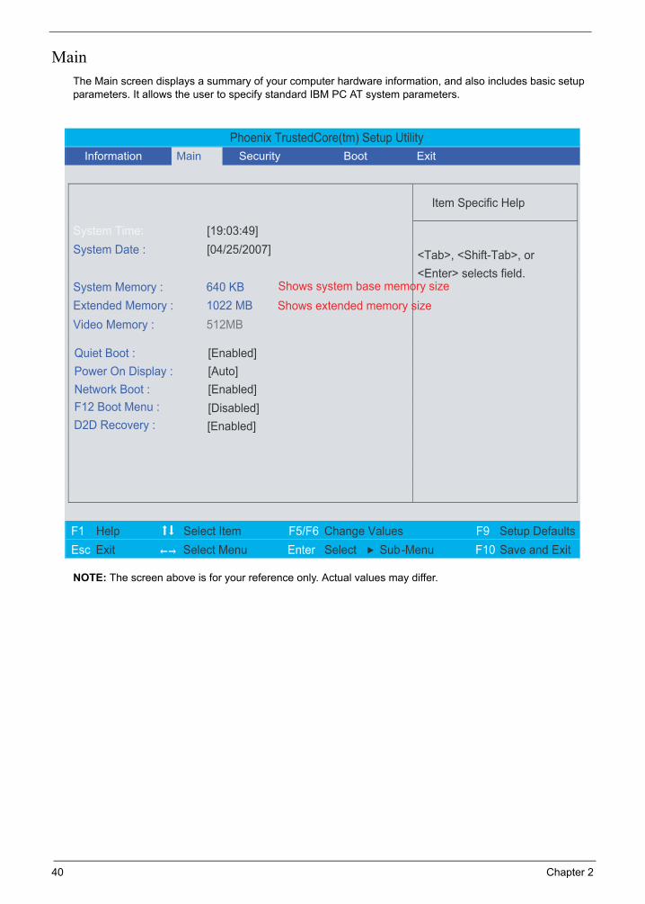
MainThe Main screen displays a summary of your computer hardware information, and also includes basic setup parameters. It allows the user to specify standard IBM PC AT system parameters.
NOTE: The screen above is for your reference only. Actual values may differ.
Phoenix TrustedCore(tm) Setup Utility
Item Specific Help
System Time: [19:03:49] System Date : [04/25/2007]
Video Memory : 512MB
Quiet Boot : [Enabled]
Power On Display : [Auto]
Network Boot : [Enabled]
F12 Boot Menu : [Disabled]
<Tab>, <Shift-Tab>, or <Enter> selects field.
F1 Help Select Item F5/F6 Change Values F9 Setup Defaults Esc Exit Select Menu Enter Select Sub-Menu F10 Save and Exit
System Memory : 640 KB Shows system base memory sizeExtended Memory : 1022 MB Shows extended memory size
D2D Recovery : [Enabled]
Information Main Security Boot Exit
40 Chapter 2

The table below describes the parameters in this screen. Settings in boldface are the default and suggested parameter settings.
NOTE: The sub-items under each device will not be shown if the device control is set to disable or auto. This is because the user is not allowed to control the settings in these cases.
Parameter Description Format/Option
System Time Sets the system time. The hours are displayed with 24-hour format.
Format: HH:MM:SS (hour:minute:second) System Time
System Date Sets the system date. Format MM/DD/YYYY (month/day/year) System Date
System Memory This field reports the memory size of the system. Memory size is fixed to 640MB
Extended Memory This field reports the memory size of the extended memory in the system. Extended Memory size=Total memory size-1MB
Video Memory Shows the Video memory size.
Quiet Boot Determines if Customer Logo will be displayed or not; shows Summary Screen is disabled or enabled. Enabled: Customer Logo is displayed, and Summary Screen is disabled.Disabled: Customer Logo is not displayed, and Summary Screen is enabled.
Option: Enabled or Disabled
Power on display Auto: During power process, the system will detect if any display device is connected on external video port. If any external display device is connected, the power on display will be in CRT (or projector) only mode. Otherwise it will be in LCD only mode.Both: Simultaneously enable both the integrated LCD screen and the system’s external video port (for an external CRT or projector).
Option: Auto or Both
Network Boot Enables, disables the system boot from LAN (remote server).
Option: Enabled or Disabled
F12 Boot Menu Enables, disables Boot Menu during POST. Option: Disabled or Enabled
D2D Recovery Enables, disables D2D Recovery function. The function allows the user to create a hidden partition on hard disc drive to store operation system and restore the system to factory defaults.
Option: Enabled or Disabled
Chapter 2 41

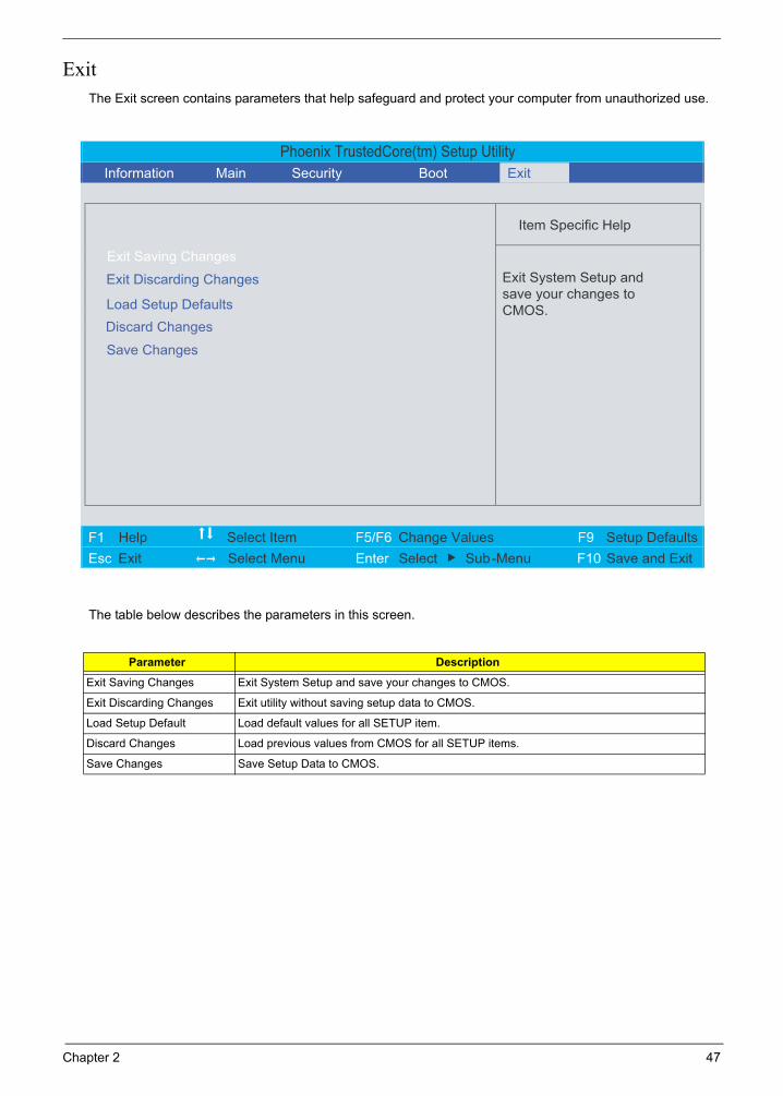
SecurityThe Security screen contains parameters that help safeguard and protect your computer from unauthorized use.
Phoenix TrustedCore(tm) Setup Utility
Item Specific Help
Supervisor Password Is : Clear User Password Is : Clear
Set Supervisor Password
Set User Password
Password on boot : [Disabled]
Supervisor Password
controls accesses to the
setup utility.
F1 Help Select Item F5/F6 Change Values F9 Setup Defaults
Esc Exit Select Menu Enter Select Sub-Menu F10 Save and Exit
[Enter]
[Enter]
Set Hard Disk Password [Enter]
Hard Disk Password Status : Clear
Information Main Security Boot Exit
42 Chapter 2

The table below describes the parameters in this screen. Settings in boldface are the default and suggested parameter settings.
NOTE: When you are prompted to enter a password, you have three tries before the system halts. Don’t forget your password. If you forget your password, you may have to return your notebook computer to your dealer to reset it.
Setting a PasswordFollow these steps as you set the supervisor, user, or hard disk password:
1. Use the w and y keys to highlight the Set Supervisor Password parameter and press the e key. The Set Supervisor Password box appears:
2. Type a password in the “Enter New Password” field. The password length can not exceed 8 alphanumeric characters (A-Z, a-z, 0-9, not case sensitive). Retype the password in the “Confirm New Password” field.
IMPORTANT: Be very careful when typing your password because the characters do not appear on the screen.
3. Press e. After setting the password, the computer sets the Supervisor Password parameter to “Set”.
4. If desired, you can opt to enable the Password on boot parameter.
5. When you are done, press u to save the changes and exit the BIOS Setup Utility.
Parameter Description Option
Supervisor Password is Shows the setting of the Supervisor password Clear or Set
User Password is Shows the setting of the user password. Clear or Set
Hard Disk Password Status Shows the setting of the hard disk password. Clear or Set
Set Supervisor Password Press Enter to set the supervisor password. When set, this password protects the BIOS Setup Utility from unauthorized access. The user can not either enter the Setup menu nor change the value of parameters.
Set User Password Press Enter to set the user password. When user password is set, this password protects the BIOS Setup Utility from unauthorized access. The user can enter Setup menu only and does not have right to change the value of parameters.
Set Hard Disk Password Press Enter to set the hard disk password. When set, this password protects the BIOS Setup Utility from unauthorized access. The user can not either enter the Setup menu nor change the value of parameters.
Password on Boot Defines whether a password is required or not while the events defined in this group happened. The following sub-options are all requires the Supervisor password for changes and should be grayed out if the user password was used to enter setup.
Disabled or Enabled
Chapter 2 43


![acer_aspire_5920_[ET] 5920g](https://static.documents.pub/doc/80x56/54e8492b4a79599f4e8b45d2/aceraspire5920et-5920g.jpg)


