ABB Industrie AG. All Rights Reserved. ACS 1000 Medium Voltage AC Drives for speed and torque control of 315 to 5000 kW / 400 to 6700 hp squirrel cage induction motors Technical Catalog Effective: October 23, 2000
Transcript
ACS 1000Medium Voltage AC Drives
for speed and torque control of315 to 5000 kW / 400 to 6700 hp
squirrel cage induction motors
Technical Catalog
Effective: October 23, 2000
ABB Industrie AG. All Rights Reserved.
We reserve all rights to this document, also in the event of patent issue orregistration of any other industrial property protection right. Misuse and inparticular duplication and forwarding to third parties are not permitted.
This document has been checked with care. However, should the user findany errors, they should please be reported to ABB Industrie AG.
The data stated in this manual is for product description purposes anddoes not represent assured characteristics. As we aim to keep our prod-ucts up to the most modern standard, differences may occur betweenentries in this technical catalog and the actual product.
2 ACS 1000 Technical Catalog
Table of Contents
Chapter 1 - Overview 7
1.1 Introduction 71.2 The Standard Solution 71.3 Key Technology 71.4 Technical Benefits 81.5 ACS 1000 Types 9
Chapter 2 - Main Features 11
2.1 IGCT Power Semiconductors 112.2 Fuseless Design 112.3 Direct Torque Control 122.4 Input Stage 132.5 Output Stage 132.6 Elementary Diagram 14
Chapter 3 - Hardware Description 17
3.1 Electromagnetic Compatibility 173.2 ACS 1000 Cabinet Layout 173.2.1 Air-cooled Type 173.2.2 Water-cooled Type 193.2.3 Power Terminals 203.3 Control Equipment 213.4 Door Locks 223.5 IP Ratings 233.6 Lifting Arrangements 233.7 Standard Color 233.8 Additional Cabinets 23
Chapter 4 - User Interfaces 25
4.1 Overview 254.2 CDP 312 Control Panel 254.3 Standard I/Os 264.4 Fieldbus Adapter Modules 314.5 PC Tools 31
ACS 1000 Technical Catalog 3
Chapter 5 - Parameters and Application Macros 33
5.1 Overview 335.2 Suitable Applications for Different Macros 335.3 Macro I/O interfaces 36
Chapter 6 - Standard Functions 39
6.1 General 396.2 Standard Control Functions 396.2.1 General Functions 396.2.2 Main Circuit Breaker Control 426.2.3 Local and Remote Control 426.2.4 Diagnostics 436.2.5 Programmable Digital and Analog Outputs 436.2.6 Scalable Analog Inputs 446.2.7 Input Signal Source Selections and
Signal Processing 446.3 Standard Protection Functions 456.3.1 Programmable Fault Functions 456.3.2 Pre-programmed Protection Functions 476.3.3 Other Protection Functions 496.4 Other Functions 496.4.1 Customer Specific Options 50
Chapter 7 - Options 51
7.1 Environmental Conditions 517.2 Converter Enclosure 517.3 Input Section 527.4 Motor Side 537.5 Converter Cooling 567.6 Converter Isolators and Bypass 597.7 Auxiliary & Control Interfaces 617.8 PC Tools 61
Chapter 8 - Selecting the Drive System 63
8.1 Overview 638.2 Main Circuit Breaker 638.2.1 Main Circuit Breaker Control 638.2.2 Tripping Loop 648.2.3 Main Circuit Breaker Features 658.3 Converter Input Transformer Selection 68
4 ACS 1000 Technical Catalog
8.4 Selection of the ACS 1000 Converter 698.4.1 ACS 1000 Output Filter 698.4.2 Non Quadratic Load Applications 698.4.3 ACS 1000 Selection Tables 708.5 Motor Selection 738.5.1 Load Capacity Curves 738.5.2 Selection Criteria 748.5.3 Retrofit 748.5.4 Torsional Excitation 75
Protection Functions 93Analog Inputs 94Analog Outputs 94Digital Inputs 95Digital Outputs 95Auxiliary Power Output 95Reference Voltage Output 96DDCS Fiber Optical Link 96Enclosures 96
Appendix C - Dimensions and Weights 97
Appendix D - Applicable Codes and Standards 101
CE Marking 101Low Voltage Directive 101Machinery Directive 101EMC Directive 102Emissions 102Immunity 102
UL Marking 103Applicable Codes and Standards 103
Appendix E - ACS 1000 Type Code 105
6 ACS 1000 Technical Catalog
Chapter 1 - Overview
This Technical Catalog describes the main electrical, mechanical andenvironmental features of the ACS 1000 – ABB’s contribution to new solu-tions of medium-voltage AC drives. In addition, the Catalog looks at thevarious options available for the drive and offers advice on selecting amotor and drive combination. It also provides useful installation tips.
The ACS 1000 is a standard, medium-voltage AC drive, rated from 315 to5000 kW (400 to 6700 hp) for motor voltages of 2.3, 3.3 and 4.0 kV.
The drive has been designed as a standard product rather than an engi-neered drive. It is, therefore, a core product of ABB, forming part of thecompany’s ACS family. As such, the drive uses standard components,software tools and design principles as employed in the low voltage ACSrange. This vastly increases the reliability of the drive and offers users aconsistent addition to the extensive ACS product range.
As a standard solution the ACS 1000 has many of the benefits associatedwith engineered drives already included. This meets the most commonsystem specifications with minimal engineering. In addition, because thedrive is pre-engineered, shorter delivery times to end-users are possible.
About 85% of all medium-voltage drives are applied in standard applica-tions such as fans, pumps, conveyors and compressors, where thecustomized engineering content is minimal. The ACS 1000 is ideally suit-able for retrofit applications, where only a small portion of the world’smotors are fitted with drives.
Industries, which can benefit from this approach, include oil and gas,mining, water, pulp & paper, cement and power generation.
Two main technology features distinguish the ACS 1000 from other typeson the market:
• The motor control platform is based on Direct Torque Control (DTC)which achieves the ultimate torque and speed performance.
DTC allows the speed of any standard squirrel cage induction motorto be controlled without the need for expensive and fragile encodersor tachogenerator feedback devices.
1.1 Introduction
1.2 The Standard Solution
1.3 Key Technology
ACS 1000 Technical Catalog 7
Chapter 1 - Overview
• For the first time in any AC drive, a new power semiconductor switch-ing device is utilized. Known as IGCT (Integrated Gate CommutatedThyristor), the device provides an intrinsically less complex, more ef-ficient and reliable drive. This is achieved by fast switching and inher-ently low losses which mean less cooling equipment is needed.
IGCTs do not require snubber circuits and allow power bridge imple-mentation with fewer power devices than conventional medium-voltage drives. While reliability is improved, the physical size of theACS 1000 is compact.
The technology described above brings many more practical benefits tothe ACS 1000, as described within this Catalog.
For instance, the use of IGCTs together with active feedback control bymeans of an LC filter results in a sinusoidal output voltage. This provesuseful in retrofit applications, as the drive is compatible with existingsquirrel cage motors without the need to derate it. There are no unduevoltage rises stressing the motor insulation and voltage reflections areeliminated on long cable runs.
Furthermore, DTC avoids any torque pulsations, which can be damagingto loads and their associated mechanical connections.
The ACS 1000 is available for use with a separately mounted input isola-tion transformer (standard) or alternatively with an integrated dry-typetransformer. This provides installation flexibility and allows for the use of oilfilled transformers which are typically mounted outdoors.
The ACS 1000 meets all common standards including IEC and EN. Inorder to meet the requirements of the North American market, theACS 1000 is also UL and Canadian UL listed. In addition, ABB has under-taken much development work to ensure that the converter adequatelymeets the requirements of the world’s harmonics standards, such asIEEE 519-1992.
For details please refer to Appendix D - Applicable Codes and Standards.
The ACS 1000 features a selection of pre-programmed and standardizedapplication macros for the configuration of inputs, outputs, signalprocessing and other parameters.
1.4 Technical Benefits
8 ACS 1000 Technical Catalog
Chapter 1 - Overview
The ACS 1000 is available as air-cooled and water-cooled types. The air-cooled ACS 1000 covers rated power outputs from 400 HP to 2250 HP(315 kW to 1600 kW). For higher power output ratings ranging from2500 HP to 6700 HP (1800 kW to 5000 kW), the converters are water-cooled.
The ACS 1000 converter is available for 3 different medium voltage levels.These are the standard motor voltages of 2.3 kV, 3.3 kV and 4.0 kV. Forinformation on solutions for retrofit applications with motor voltages of upto 7.2 kV please contact your ABB representative.
The table below provides an overview of the rated output power range,covering air and water-cooled converters for all three medium voltagelevels.
For further details, refer to Chapter 8 - Selecting the Drive System.
Table 1-1 Standard power ranges for ACS 1000 converters
** The power ratings apply to typical 4 pole motors. For those motors thefrequency converter has a built-in overloadability of 10%. When selectingthe frequency converter it should be observed that the rated current of theACS 1000 must be higher than or equal to the rated motor current in orderto achieve the rated motor power given in the table.
Note: For air-cooled units (with enclosure class IP21) the load capacity(current and power) depends on the altitude and the ambient temperatureat the installation site. In case of water-cooled units the load capacitydepends on the cooling water temperature at the installation site. Fordetails on the derating factors, see Appendix B - Technical Data.
1.5 ACS 1000 Types
MotorVoltage
(kV)
Type ofCooling
Rated MotorPower Range**
HP
Max. cont.Power ofACS 1000
(kVA)
Frame Size
2.3 Air 400 - 2250 400 - 2000 A1 - A3
2.3 Water 2500 - 4000 2300 - 3600 W1 - W2
3.3 Air 450 - 2250 400 - 2150 A1 - A3
3.3 Water 2500 - 6700 2400 - 5950 W1 - W3
4.0 Air 400 - 2250 400 - 2000 A1 - A3
4.0 Water 2500 - 6700 2300 - 5800 W1 - W3
ACS 1000 Technical Catalog 9
Chapter 1 - Overview
10 ACS 1000 Technical Catalog
Chapter 2 - Main Features
ABB researched and designed the Integrated Gate Commutated Thyristor(IGCT) specifically for the medium voltage market. IGCTs provide highspeed switching like IGBTs (Insulated Gate Bipolar Transistors) and at thesame time provide high voltage blocking and low loss conduction likeGTOs (Gate Turn-Off Thyristors). The result is a fast, low loss device thatcan be used at medium voltage levels without resorting to series topolo-gies. It transcends both of the older technologies from which it evolved.IGCTs also provide other benefits:
• Freewheeling diode is integrated into the same package
• Snubber circuits are not required
• Gating circuitry is packaged with the power device
• High reliability (low total parts count)
• High power density (combination of low total parts count and lowpower losses)
• Self-protecting against destructive failures.
All these features combined provide a medium voltage power switchingdevice with the best combination of performance, reliability, efficiency, andspace effectiveness available in the market today.
The ACS 1000 features a fuseless protected medium voltage drive.
The patented design uses the new power semiconductor switching device,IGCT, for circuit protection.
The IGCT, which is placed between the DC-link and the rectifier, can,unlike conventional fuses, directly isolate the inverter of the drive systemfrom the power supply side. This is achieved within 25 microseconds,which is 1000 times faster than the operational performance of fuses.
Using the IGCT as an integrated protection device leads to a lower partscount within the drive system making the ACS 1000 a drive withoutstanding reliability.
The reason why IGCTs are capable of performing a protection function,unlike other power semiconductor devices, lies in their low onstate lossesand their ability to turn off at high speed at medium voltage levels.
2.1 IGCT Power Semiconductors
2.2 Fuseless Design
ACS 1000 Technical Catalog 11
Chapter 2 - Main Features
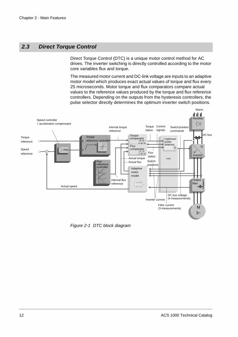
Direct Torque Control (DTC) is a unique motor control method for ACdrives. The inverter switching is directly controlled according to the motorcore variables flux and torque.
The measured motor current and DC-link voltage are inputs to an adaptivemotor model which produces exact actual values of torque and flux every25 microseconds. Motor torque and flux comparators compare actualvalues to the reference values produced by the torque and flux referencecontrollers. Depending on the outputs from the hysteresis controllers, thepulse selector directly determines the optimum inverter switch positions.
Figure 2-1 DTC block diagram
2.3 Direct Torque Control
Switchpositions
Torque
reference
Speed
reference
Rectifier
=~Inverter
Torquecomparator
Fluxcomparator
Adaptivemotormodel
Torquereference controller
PID
FluxreferencecontrollerU
fU
fT
f
Speed controller+ acceleration compensator
Actual speed
Internal fluxreference
Actual torqueActual flux
Inverter current
DC bus voltage
DC bus
Fluxstatus
Torquestatus
Controlsignals
ASIC
Switch positioncommands
Mains
Internal torquereference
Optimumpulseselector
Filter current
Outputfilter
(3 measurements)
(4 measurements)
M3~
12 ACS 1000 Technical Catalog
Chapter 2 - Main Features
How does DTC differfrom PWM Flux Vector
Drives?
In DTC, each switching instance is determined separately based on thevalues of flux and torque, rather than switching in a predetermined patternas in conventional PWM flux vector drives.
Table 2-1 DTC versus PWM Flux Vector controlled drives
For more information on DTC, please refer to the Technical GuideNo. 1 Direct Torque Control (3AFY 58056685 R0025).
The ACS 1000 features a 12-pulse diode rectifier input stage. This isadequate for most networks and normally meets the harmonic require-ments demanded by standards such as IEEE 519.
For networks that are more demanding, the ACS 1000 can be suppliedoptionally with a 24-pulse configuration for water-cooled and for air-cooledtypes.
As a standard the ACS 1000 is equipped with a low pass LC sine filter inits output stage. Current feedback is used to actively control filter opera-tion. The low pass frequency is designed to be well below the lowestswitching frequency used by the inverter output stage. This greatlyenhances the purity of both the voltage and current waveforms applied tothe motor. This in turn provides many important benefits:
• Harmonic heating is virtually eliminated. The drive may be used tosupply standard medium voltage motors (existing or new) without ap-plying thermal derating factors.
DTC Flux Vector
Switching based on core motorvariables Flux and Torque
Switching based on separate control ofmagnetising and torque producingcomponents of current
Shaft speed and position not required Mechanical speed is essential. Requiresshaft speed and position(either measured or estimated)
Each inverter switching is determinedseparately (every 25 µs).
Inverter switching based on averagereferences to a PWM modulator. Thisresults in delays in response and wastedswitchings.
Torque Step Rise Time (open loop) isless than 10 msec.
Torque Step Rise TimeClosed Loop 10 to 20 msec.Sensorless 100 to 200 msec.
2.4 Input Stage
2.5 Output Stage
ACS 1000 Technical Catalog 13
Chapter 2 - Main Features
• Voltage reflection and the associated occurrence of voltage doublingat the motor input terminals is no longer an issue (the causal high fre-quency content does not exist). Therefore, any standard medium volt-age winding insulation system (existing or new) is compatible with theACS 1000.
• The maximum length of the motor cables is not limited by theACS 1000 (normal voltage drop restrictions as found in any electricalinstallation still apply).
• Motor bearing failures attributable to capacitively coupled high fre-quency current are no longer a problem (the causal high frequencycommon mode voltage is eliminated).
• Motor insulation is not subject to the common mode voltage typical forother drive topologies.
Figure 2-2 and Figure 2-3 show the elementary circuit diagram of the 12-pulse and the 24-pulse versions of the ACS 1000.
The 3-phase AC line voltage is supplied to the rectifier bridges through the3-winding converter transformer. In order to obtain 12 or 24-pulse rectifi-cation, appropriate phase shift is necessary between the secondary wind-ings of the transformer.
The two fuseless rectifier bridges in the 12-pulse scheme (Figure 2-2) areconnected in series, such that the DC voltages are added up. Therefore,the full DC bus current flows through both bridges. In the 24-pulsescheme, 2 such bridge arrangements are connected in parallel as shownin Figure 2-3.
Figure 2-2 Elementary diagram - ACS 1000, 12-pulse version
2.6 Elementary Diagram
DiodeRectifier
IntermediateDC Link
Three LevelInverter
OutputSine Filter
Squirrel CageInduction Motor
NP M
ProtectionIGCTs
3
MediumVoltageSwi tchgear
Main CircuitBreaker
ConverterTransformer
(Option)
14 ACS 1000 Technical Catalog
Chapter 2 - Main Features
Figure 2-3 Elementary diagram - ACS 1000, 24-pulse version
Each leg of the 3-phase inverter bridge consists of a combination of 2IGCTs for 3-level switching operation: with the IGCTs the output isswitched between positive DC voltage, neutral point (NP) and negative DCvoltage. Hence both the output voltage and the frequency can becontrolled continuously from zero to maximum, using Direct TorqueControl.
At the converter output a LC filter is used for reducing the harmoniccontent of the output voltage. With this filter, the voltage waveform appliedto the motor is nearly sinusoidal (see Figure 2-4). Therefore, standardmotors can be used at their nominal ratings. The filter also eliminates allhigh dv/dt effects and thus voltage reflections in the motor cables andstresses to the motor insulation are totally eliminated.
Figure 2-4 Voltage and current waveforms at converter output
The riveted and folded cabinet construction of the ACS 1000 ensures anextremely strong yet flexible and self-supporting framework which avoidsthe need for additional skeletal support. Compared with traditional boltedframes the cabinet provides extremely effective protection against electro-magnetic emissions.
The design fulfils the requirements of international standards likeUL 347A. For details please refer to Appendix D - Applicable Codes andStandards.
Electromagnetic Compatibility (EMC) has been achieved by applying acabinet design consisting of folded, galvanized sheet metal plates andminimizing the spacing between the rivets. The cabinet’s inside walls arenot painted, because paint tends to reduce the effectiveness of metallicbonding which is paramount to successful EMC.
Accordingly, only the front of the ACS 1000 cabinet is painted while allother walls are galvanized. However, the cabinet can be ordered optionallywith the whole of the outside painted.
EMC performance is further enhanced by the use of metal cable channels.
3.2.1 Air-cooled Type
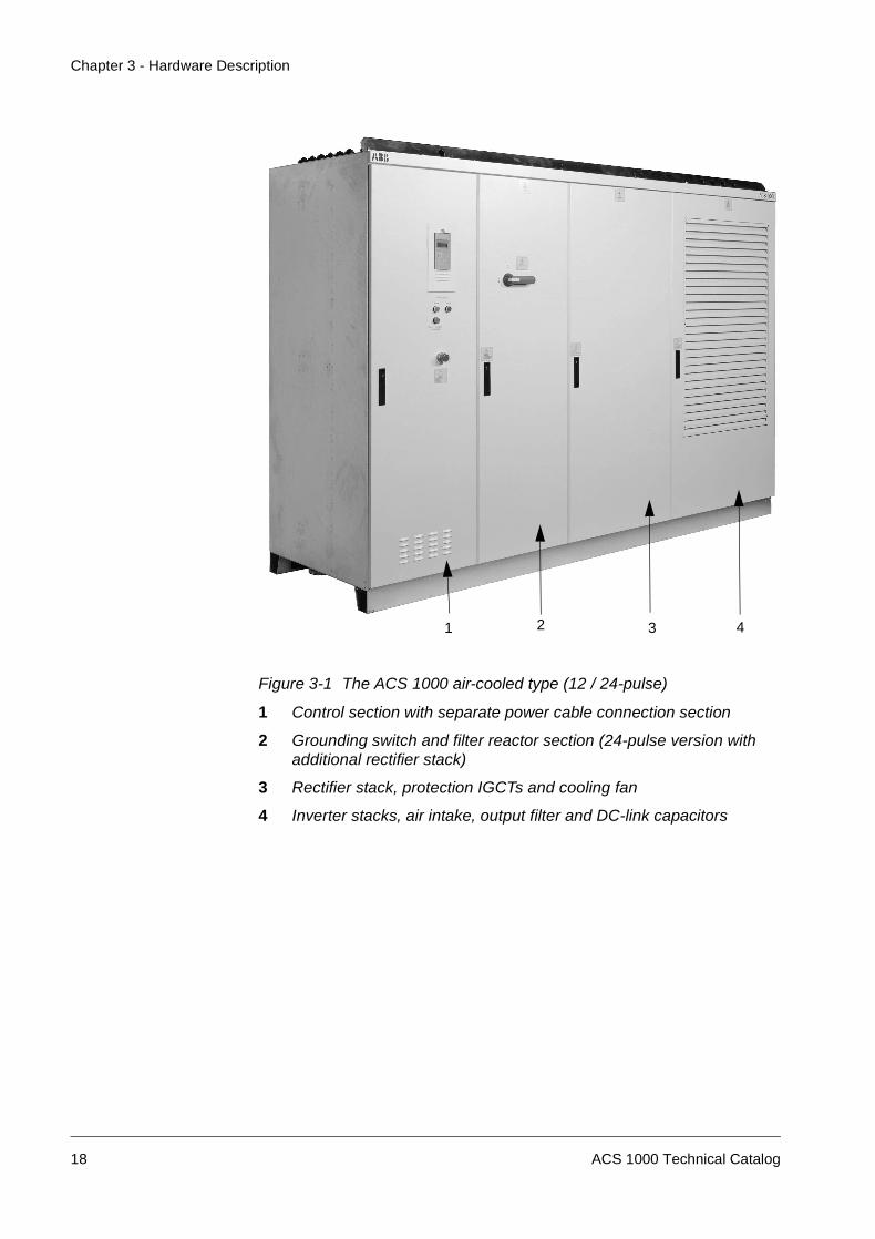
The air-cooled type of the ACS 1000 is designed with inverter stacks,output filter and DC-link capacitor in one section (see Figure 3-1). Thissection experiences maximum air flow which is advantageous for thetemperature sensitive capacitors. The construction of the inverter stacksallows easy exchange of IGCTs by means of a specially designed toolwhich is part of the supply.
The middle section accommodates cooling fan, rectifier stack, protectionIGCTs and filter reactor. The construction is such that the fan can beexchanged easily.
The air intake is provided with an air filter in order to prevent dust andparticles from entering into the converter. The air filter can be replacedfrom outside while the drive system is in operation.
3.1 Electromagnetic Compatibility
3.2 ACS 1000 Cabinet Layout
ACS 1000 Technical Catalog 17
Chapter 3 - Hardware Description
Figure 3-1 The ACS 1000 air-cooled type (12 / 24-pulse)
1 Control section with separate power cable connection section
2 Grounding switch and filter reactor section (24-pulse version withadditional rectifier stack)
3 Rectifier stack, protection IGCTs and cooling fan
4 Inverter stacks, air intake, output filter and DC-link capacitors
2 3 41
18 ACS 1000 Technical Catalog
Chapter 3 - Hardware Description
3.2.2 Water-cooled Type
12-pulse Version The water-cooled type of the ACS 1000 (see Figure 3-2) is equipped witha closed circuit water cooling system. Part of the cooling system is a fanand an air-to-water heat exchanger to maintain cooling of all componentswhich cannot be cooled by water.
As with the air-cooled type, the construction of the inverter stacks allowseasy exchange of IGCTs by means of a specially designed tool which ispart of the supply.
Figure 3-2 The ACS 1000 water-cooled type (12-pulse)
1 Control section with separate power cable connection section
2 Filter and DC components section (grounding switch, filter reactorand filter capacitors, DC-link capacitors, common mode choke)
24-pulse Version The cabinet layout of the water-cooled 24-pulse version of the ACS 1000is identical to the 12-pulse version, with the exception that there is an addi-tional cabinet on the left hand side of the control section, containing theextra rectifier stacks for 24-pulse operation.
3.2.3 Power Terminals
The leftmost section (Figure 3-1 and Figure 3-2) contains the swing framewith the control equipment (see Section Control Equipment, page 21).Behind this swing frame and a protective separation door is the drive’spower terminal section with busbars for mains and motor cables. Toprovide optimum access to the power terminals, the swing frame can beopened more than 120°.
Please refer to Appendix A - Installation Guidelines for further details oncable entry and connection.
20 ACS 1000 Technical Catalog
Chapter 3 - Hardware Description
The layout of the control cabinet is identical for all converter types.
The control hardware (processor and communication boards) aremounted on the swing frame. Details can be seen in Figure 3-3.The customer I/Os are located behind the swing frame on the right sidewall (see Figure 3-4). Terminals for customer control and protectionsignals as well as for auxiliary power supply are also located there.
Figure 3-3 Control section with open front door
3.3 Control Equipment
Swing frame
Electronic powersupply board (EPS)
AMC3 control board
Interface board
IOEC1 board
∆p-transmitters(air- cooled
converters only)
Motor starters andcircuit breakers
Aux. supplytransformer
Batteries
Pulse encoder
Fieldbus interface
ACS 1000 Technical Catalog 21
Chapter 3 - Hardware Description
Figure 3-4 Control section with swing frame removed
All doors are hinged and locked using carriage key locks.
The doors of the power sections of the drive are electromechanically inter-locked with the safety grounding switch and with the main circuit breakerupstream of the converter transformer. This interlock system ensures thatnone of the power cabinets can be opened until the main source of poweris disconnected, the DC-link capacitors are discharged and the safetygrounding switch is closed. Additionally the same interlock system insuresthat power cannot be initialized to the drive unless the doors are closedand the safety grounding switch has been opened.
IOEC2 board(standard)
Access door to powercable connection
section
IOEC3 board (stan-dard for water-cooled
converters)
IOEC4 board(optional)
Terminals for aux.voltages, control sig-
nals and tripping loop
3.4 Door Locks
22 ACS 1000 Technical Catalog
Chapter 3 - Hardware Description
The doors of the control section and of the cooling section (water-cooledtype) are not linked to the interlocking system. They can be opened at anytime. The high voltage busbar section is located behind the control swingframe and separated from the control section by a bolted protective shield.
The power section doors of all additional cabinets (e.g. additional rectifiercabinet, braking chopper cabinet) are monitored by separate doorswitches since they are not included in the electromechanical interlocksystem. These door monitoring switches are wired to the drive’s trippingloop. If any of the doors are opened during operation, the MCB will betripped immediately.
The standard ACS 1000 cabinet is rated IP21 for air-cooled and IP 31 forwater-cooled types. Higher IP ratings are available as options. SeeChapter 7 - Options for further details.
The cabinets are fitted with lifting lugs as standard.
The standard color is RAL 7035 (light grey). Other colors are available onrequest.
The ACS 1000 cabinet system provides the flexibility to add furthersections to the converter at any time. Sections can be added in width of600, 800 and 1000 mm (24, 32 and 39 inches).
3.5 IP Ratings
3.6 Lifting Arrangements
3.7 Standard Color
3.8 Additional Cabinets
ACS 1000 Technical Catalog 23
Chapter 3 - Hardware Description
24 ACS 1000 Technical Catalog
Chapter 4 - User Interfaces
The ACS 1000 can be controlled from several control locations:
• The detachable CDP 312 control panel mounted on the ACS 1000front door of the control section
• External control devices, e.g. a supervisory control system,connected to the analog and digital I/O terminals on the standard I/OBoards (IOEC)
• Fieldbus adapter modules
• PC Tools (DriveWindow and DriveSupport) hooked up via a PCadapter to the ACS 1000 control board.
The CDP 312 Control Panel is the basic user interface for monitoring,adjusting parameters and controlling the ACS 1000 converter operation.
Figure 4-1 CDP 312 Control Panel
4.1 Overview
4.2 CDP 312 Control Panel
ACT PAR FUNC DRIVE
ENTER
LOC
REM
RESET REF
1 L -> 1242rpm I
SPEEDCURRENT
TORQUE
76.00 A1242.0rpm86.00 %
Enclosure class IP54 when attached tothe Control Panel Mounting Platform
Multilingual Alphanumeric Display(4 lines x 20 characters)
Plain text messages available inseveral languages
Control Panel Mode Selection keys
Double Up Arrow, Up ArrowEnterDouble Down Arrow, Down Arrow
Local/Remote, Reset, Reference andStart keys
Forward, Reverse and Stop keys
ControlPanelDisplay
ControlPanelKeypad
ACS 1000 Technical Catalog 25
Chapter 4 - User Interfaces
Using the CDP 312 panel it is possible to
• enter start-up data into the drive
• set a reference signal and give Start, Stop and Direction commands
• display actual values (three values can be read simultaneously)
• display and adjust parameters
• display information on the most recent forty fault events.
The standard I/O-boards offer a number of pre-programmed analog anddigital I/Os which are sufficient for most applications. For a wider range ofsignal interfaces optional I/O-boards can be ordered for water and air-cooled ACS 1000 to provide extended protection for transformer andmotor, external cooling equipment (e.g. fans, chillers), on-linesynchronization logic and other customer requirements.
The air-cooled ACS 1000 is equipped with two I/O-boards (IOEC1 andIOEC2) as a standard with the option of two additional I/O-boards (IOEC3and IOEC4). The water-cooled ACS 1000 is equipped with three I/O-boards (IOEC1, IOEC2, IOEC3) with the option of one aditional I/O-board(IOEC4).
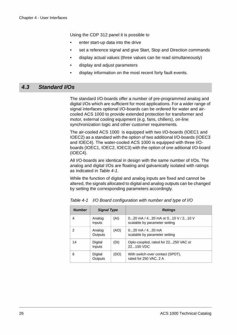
All I/O-boards are identical in design with the same number of I/Os. Theanalog and digital I/Os are floating and galvanically isolated with ratingsas indicated in Table 4-1.
While the function of digital and analog inputs are fixed and cannot bealtered, the signals allocated to digital and analog outputs can be changedby setting the corresponding parameters accordingly.
4.3 Standard I/Os
Table 4-1 I/O Board configuration with number and type of I/O
Number Signal Type Ratings
4 AnalogInputs
(AI) 0...20 mA / 4...20 mA or 0...10 V / 2...10 Vscalable by parameter setting
2 AnalogOutputs
(AO) 0...20 mA / 4...20 mAscalable by parameter setting
14 DigitalInputs
(DI) Opto-coupled, rated for 22...250 VAC or22...150 VDC
6 DigitalOutputs
(DO) With switch-over contact (SPDT),rated for 250 VAC, 2 A
26 ACS 1000 Technical Catalog
Chapter 4 - User Interfaces
Standard I/Os are marked in the following tables with a dot ( ). The letter(W) indicates that these I/Os are standard for the water-cooled ACS 1000.A signal name beginning with a slash (/) indicates a signal which is truewhen its status is low.i
Table 4-2 I/O Signals: remote control interface
Type Signal Name Remarks Standard
DI STANDARD INPUT 1 Macro specific I/O *
DI STANDARD INPUT 2 Macro specific I/O *
DI STANDARD INPUT 3 Macro specific I/O *
DI STANDARD INPUT 4 Macro specific I/O *
DI STANDARD INPUT 5 Macro specific I/O *
DI STANDARD INPUT 6 Macro specific I/O *
DI DISABLE LOCAL Remote input to disable thepossibility for a local/remoteswitch-over from the CDP 312control panel
DI REM ORD MCB CLOSE Remote request for closingthe main circuit breaker
DI REM ORD MCB OPEN Remote request for openingthe main circuit breaker
DI REMOTE RESET Remote fault reset (someconverter related faultscannot be reset remotely)
DO DRIVE READY Status output “Drive Ready”(i.e. MCB closed, DC-linkcharged, no lockout active)
DO DRIVE RUNNING Status output “Drive Running”
DO DRIVE ALARM Status output “Drive Alarm”
DO DRIVE TRIP Status output “Drive Tripped”
DO LOCAL MODE Local mode operation statusindication
AI REF VALUE 1 Macro specific I/O
ACS 1000 Technical Catalog 27
Chapter 4 - User Interfaces
* see Chapter 6 - Standard Functions
AI REF VALUE 2 Macro specific I/O
AO SHAFT SPEED ACT VAL Actual speed monitoringoutput
AO MOT CURRENT ACT VAL /MOT TORQUE ACT VAL
Actual current / torquemonitoring output(programmable)
Table 4-3 I/O Signals: main circuit breaker
Type Signal Name Remarks Standard
DI MCB IS CLOSED Status feedback from themain circuit breaker
DI MCB IS OPEN Status feedback from themain circuit breaker
DI MCB IS AVAILABLE Status feedback from themain circuit breaker, showingthat the breaker is faulty,drawn-out or in test position
DO MCB ORD CLOSE Drive command to close themain circuit breaker (pulsesignal or maintained)
DO /MCB ORD OPEN Drive command to open themain circuit breaker (pulsesignal or maintained)
DO /MCB ORD TRIP Hardware tripping loop to themain circuit breaker (signalactive when low)
Table 4-4 I/O Signals: transformer
Type Signal Name Remarks Standard
DI /EXT TRAFO PROT TRIP Initiates a main circuit breakertrip (included in hardwiredtripping loop)
DI OIL LEVEL ALARM Transformer oil level alarmindication
W
Table 4-2 I/O Signals: remote control interface (continued)
DI BUCHHOLZ ALARM Transformer alarm indicationfrom Buchholz relay
W
DI /BUCHHOLZ TRIP Transformer trip indicationfrom Buchholz relay
W
AI OIL TEMP, or
TRAFO WDG TEMP
Temperature measurement oftransformer oilTemperature measurement oftransformer winding
W
Table 4-5 I/O Signals: motor
Type Signal Name Remarks Standard
DI /EXT MOT PROT TRIP Initiates a main circuit breakertrip (included in hardwiredtripping loop)
DI EXT MOT PROT ALARM (External) motor protectionalarm indication
W
DI MOT COOLING ALARM (External) motor coolingalarm indication
W
DI /MOT COOLING TRIP (External) motor cooling tripindication
W
DI VIBRATION SV ALARM Motor vibration alarmindication
W
DI /VIBRATION SV TRIP Motor vibration trip indication W
DI /OVERSPEED TRIP Motor overspeed trip(included in hardwiredtripping loop)
W
AI MOT WDG TEMP PH U Motor winding temperature
AI MOT WDG TEMP PH V Motor winding temperature
AI MOT WDG TEMP PH W Motor winding temperature
Table 4-4 I/O Signals: transformer (continued)
Type Signal Name Remarks Standard
ACS 1000 Technical Catalog 29
Chapter 4 - User Interfaces
AI BRG TEMP DE Motor bearing temperature ofdriven end
W
AI BRG TEMP NDE Motor bearing temperature ofnon-driven end
W
Table 4-6 I/O Signals: process
Type Signal Name Remarks Standard
DI /PROCESS STOP Remote process stop input tostop the drive (signal activewhen low)
DI /INT/EXT EMERGENCY OFF Emergency OFF (signalactive when low) fromprocess side to trip the maincircuit breakerinstantaneously(included in hardwiredtripping loop)
Table 4-7 I/O Signals: Others
Type Signal Name Remarks Standard
DI /SUPPL VOLT UNBALANCE Trip from external voltageunbalance relay (signal activewhen low)
DI EXT WTR COOLING ALARM Alarm indication from externalwater cooling unit
DI /EXT WTR COOLING TRIP Trip (active when low) fromexternal water cooling unit
DI BRAKE CHOP FAN ALARM Alarm signal from brakingchopper
DI BRAKE CHOP TEMP TRIP Trip signal from brakingchopper
DI INPUT ISOLATOR OPEN Status input
DI INPUT ISOLATOR CLOSED Status input
DI OUTPUT ISOLATOR OPEN Status input
DI OUTPUT ISOLATORCLOSED
Status input
AI OUTSIDE AIR TEMP Temperature measurement ofoutside air
Table 4-5 I/O Signals: motor (continued)
Type Signal Name Remarks Standard
30 ACS 1000 Technical Catalog
Chapter 4 - User Interfaces
A fieldbus module may be used for controlling and monitoring theACS 1000 instead of using the conventional hard-wired I/Os. There areseveral fieldbus adapter modules available for the ACS 1000.
For further details, see Chapter 7 - Options.
DriveWindow offers several functions for commissioning and monitoringABB products. All the functions are available from the Menubar or theToolbar of the program. In DriveWindow the user has the choice betweentwo special displays and six different tools.
For further details, see Chapter 7.8 PC Tools.
4.4 Fieldbus Adapter Modules
4.5 PC Tools
ACS 1000 Technical Catalog 31
Chapter 4 - User Interfaces
32 ACS 1000 Technical Catalog
Chapter 5 - Parameters and Application Macros
Parameters allow the user specific configuration of the ACS 1000. Theycan be set using the CDP 312 control panel.
The application macros consist of pre-programmed parameter sets thatare adapted for a specific application. They offer pre-set signal interfacesfor opening/closing the main circuit breaker, starting/stopping the drivesystem and setting reference values.
Depending on the process, the appropriate macro can be selected, thusenabling a quick and easy start-up of the ACS 1000.
Using an application macro has the advantage that the number ofindividual parameters to be set during start-up is minimized. All para-meters have factory-set default values. Leaving them unchanged, a goodsystem performance is achieved in typical situations. These default valuescan be left unchanged or they can be set individually according to theneeds of the customer.
The ACS 1000 can be operated with one of the following standard macros:
• Factory
• Speed Control
• Hand/Auto
• PID Control
• Torque Control
• Sequential Control
• Master/Follower
• User 1
• User 2
Factory The Factory Macro is the default-set macro. It covers most of the commonapplications, such as:
• Pump, fan and other industrial processes with a square torque char-acteristic
• Conveyors and other industrial drives requiring constant torque.
5.1 Overview
5.2 Suitable Applications for Different Macros
ACS 1000 Technical Catalog 33
Chapter 5 - Parameters and Application Macros
Speed Control The Speed Control Macro is essentially the same as the Factory Macro.The only difference to the Factory Macro is that a loading of the SpeedControl Macro will not affect the currently set motor control parameters(when loading the Factory Macro all parameters will be reset to theirdefault value).
Hand/Auto The Hand/Auto Macro is suitable for applications where the speed has tobe controlled automatically by a process control system and manually byan external control panel. The active control location is selected via adigital input.
The macro is also recommended when the drive has to be controlled fromtwo external control stations. The active control station for starting /stop-ping and setting of the reference value is selected via a digital input.
PID Control The PID Macro is intended for the use with closed loop control systemssuch as pressure control, level control and flow control. For example:
• Booster pumps of municipal water supply systems
• Booster pumps of district heating systems
• Automatic level control of water reservoirs
• Speed control of different types of material handling systems wherethe material flow has to be regulated.
The PID-controller is incorporated into the ACS 1000 software. It is acti-vated by selecting the PID Macro.A process reference value is set via an analog input or by using the controlpanel of the ACS 1000. The actual process value is connected to a dedi-cated analog input.The internal PID-controller of the ACS 1000 eliminates the need of a sepa-rate PID-controller (no additional installation and wiring required).
Figure 5-1 Example of an application with PID control loop
Actual Value
Reference
LevelTrans-ducer
Pump
ACS 1000 converter
34 ACS 1000 Technical Catalog
Chapter 5 - Parameters and Application Macros
Torque Control The macro is intended for processes requiring torque control, e.g. mixersand slave drives. The torque reference comes from a process automationsystem or a control panel.
Sequential Control The Sequential Control Macro is aimed for processes where differentconstant speed settings and/or different acceleration/deceleration rampsare required in addition to an adjustable speed reference value. Thedifferent settings can be selected automatically by a process controlsystem or they can be activated manually by selector switches which areconnected to the corresponding digital inputs.
Master/Follower The Master/Follower Macro is designed for applications with severalACS 1000 where the motor shafts are coupled to each other by gearing,chain, belt etc. Thanks to the Master/Follower macro the load can beevenly distributed between the drives or depending on the process atsome other ratio.
User 1 / User 2 The User Macro 1 and 2 allows to save a complete set of customizedparameters and to recall it at a later instant or to download it to anotherACS 1000.
ACS 1000 Technical Catalog 35
Chapter 5 - Parameters and Application Macros
The following tables give an overview of the pre-set digital and analoginputs and outputs, regarding opening/closing the main circuit breaker,starting/stopping the drive system, setting reference values and statusfeedback signals. All other customer interface signals are the same foreach application macro, see Chapter 4 - User Interfaces.
All macro specific I/Os are available on the standard IOEC boards. Onlythe PID macro requires IOEC 4 board.
5.3 Macro I/O interfaces
Table 5-1 Macro specific digital and analog inputs
Macro I/Os I/O functions
FactorySpeed
DI MCB open/close commandsStart/ stop commandsSelection of directionSelection of 2 accel/decel rampsSelection of 2 const. speedsProcess stop or run enable
AI 2 speed reference values
Hand/Auto DI Selection of hand/auto modeMCB open/close commands in hand modeMCB open/close commnands in auto modeStart/ stop commands in hand modeStart/stop commands in auto modeSelection of 1 const. speedProcess stop or run enable
AI Speed reference value in hand modeSpeed reference value in auto mode
PID DI MCB open/close commandsStart/stop commandsSelection of directionSelection of reference valueSelection of 2 accel/decel rampsSelection of 3 const. speedsProcess stop or run enable
AI Reference valueActual value, process feedbackActual value process feedback
Torque DI MCB open/close commandsStart/stop commandsSelection of speed/torque controlSelection of 2 accel/decel rampsSelection of 1 constant speedProcess stop or run enable
AI Speed reference valueTorque reference value
36 ACS 1000 Technical Catalog
Chapter 5 - Parameters and Application Macros
The pre-set digital and analog outputs available for external use are thesame for each macro.
Table 5-2 Macro specific digital and analog outputs
Sequential DI MCB open/close commandsStart/stop commandsSelection of 2 accel/decel rampsSelection of 7 const. speedsProcess stop or run enable
AI Reference value
Master Follower DI MCB open/close commandStart/stop commandSelection of 1 accel/decel rampSelection of 3 const. speedsProcess stop or run enable
AI Speed reference value
User 1 / User 2 Depends on application
Table 5-1 Macro specific digital and analog inputs (continued)
Macro I/Os I/O functions
Macro I/Os I/O functions
FactorySpeedPIDTorqueSequentialMaster/Follower
DO Drive readyDrive runningDrive alarmDrive trip
AO Motor frequencyMotor torqueMotor speedMotor torque filtered
ACS 1000 Technical Catalog 37
Chapter 5 - Parameters and Application Macros
38 ACS 1000 Technical Catalog
Chapter 6 - Standard Functions
The ACS 1000 is configured and customized by means of applicationparameters. These parameters can be altered by the user, either bymeans of the integrated CDP 312 control panel or by using a PC and theDriveWindow software package, as described in Chapter 7 - Options.
Control and monitoring functions of the ACS 1000 can be activated bysetting parameters one by one or by invoking an Application Macro (seeChapter 5 - Parameters and Application Macros) which is optimized for aparticular application. Therefore some of the functions described in thischapter will be configured automatically if an application macro isselected.
This chapter provides information about the standard control, monitoringand protection functions for the ACS 1000. A description of the basic I/Odevices and the application macros of the ACS 1000 can be found inChapter 4 - User Interfaces and Chapter 5 - Parameters and ApplicationMacros.
6.2.1 General Functions
Motor ID Calculation Based on the nameplate data all ACS 1000 internal motor controlparameters will be automatically calculated. This procedure is usuallyperformed once during commissioning. However, the procedure can berepeated whenever required (e.g. when the ACS 1000 will be hooked upto another motor).
Full Torque at ZeroSpeed
A motor fed by the ACS 1000 can develop short-term motor nominaltorque at start-up without any pulse encoder or tachogenerator feedback.This feature is essential for constant torque applications. However, ifpermanent operation at zero speed is required, a pulse encoder has to beused.
Enhanced Flying Start This feature allows a rotating motor (e.g. a turbo-pump or a fan) to betaken over by the ACS 1000. By means of the flying start function thefrequency of the motor is detected and the motor is started-up again by theACS 1000.
6.1 General
6.2 Standard Control Functions
ACS 1000 Technical Catalog 39
Chapter 6 - Standard Functions
Flux Optimization Flux optimization of the ACS 1000 reduces the total energy consumptionand motor noise level when the drive operates below the nominal load.The total efficiency (ACS 1000 and motor) can be improved by 1...10%,depending on the load torque and speed. This function is activated byparameters.
Power Loss Ride-Through
If the incoming supply voltage is cut off the ACS 1000 will continue tooperate in an active but non-torque producing mode by utilizing the kineticenergy of the rotating motor and load. The ACS 1000 will be fully active aslong as the motor rotates and generates energy to the ACS 1000. Powerloss ride through can be enabled by parameters.
Auxiliary Ride Through The auxiliary ride through function guarantees correct fault indication andproper trip sequencing, in the event that the auxiliary power source feedingthe drive is lost. The function is activated by a parameter. During ridethrough the power for the control circuits of the ACS 1000 is supplied byinternal batteries. The ride through time is limited to 1 sec.
Acceleration andDeceleration Ramps
ACS 1000 provides two user-selectable acceleration and decelerationramps. It is possible to adjust the acceleration/deceleration times(0...1800 s) and select the ramp shape. Switching between the two rampscan be controlled via a digital input.
The available ramp shape alternatives are:
Linear: Suitable for drives requiring long acceleration/deceleration whereS-curve ramping is not required.
S1: Suit. for short acc./dec. times.
S2: Suit. for medium acc./dec. times
S3: Suit. for long acc./dec. times.
S-curve ramps are ideal for conveyorscarrying fragile loads, or other applica-tions where a smooth transition isrequired when changing from onespeed to another.
Critical Speed There is a Critical Speed function available for applications where it isnecessary to avoid certain motor speeds or speed bands, for example dueto mechanical resonance problems. The ACS 1000 makes it possible toset up five different speed settings or speed bands which will be avoidedduring operation.
Linear
1 t (s)
Motor
1.25 2
S1
S2
S3
speed
40 ACS 1000 Technical Catalog
Chapter 6 - Standard Functions
Each critical speed setting allows theuser to define a low and a high speedlimit. If the speed reference signalrequires the ACS 1000 to operatewithin this speed range the CriticalSpeeds function will keep theACS 1000 operating at the low (orhigh) limit until the reference is out ofthe critical speed range. The motor isaccelerated/decelerated through thecritical speed band according to theacceleration or deceleration ramp.
Constant Speeds Up to 15 constant speeds can be programmed and selected by digitalinputs. If activated the external speed reference is overwritten. If theSequential Control Macro is used a standard set of parameter values isselected automatically.
Accurate SpeedControl
The static speed control error is typically +0.1% (10 % of nominal slip) ofthe motor nominal speed, which satisfies most industrial applications.
Accurate TorqueControl without Speed
Feedback
The ACS 1000 can perform precisetorque control without any speed feed-back from the motor shaft. With torquerise time less than 10 ms at 100%torque reference step compared toover 100 milliseconds in frequencyconverters using sensorless fluxvector control, the ACS 1000 isunbeatable.
By applying a torque reference insteadof a speed reference, the ACS 1000will maintain a specific motor torquevalue; the speed will be adjusted auto-matically to maintain the requiredtorque.
Table 6-1 Typical performance figures for torque control, when DirectTorque Control is used
* When operated around zero frequency, the error may be bigger.
s 1 Lows1 High s2 Low s2 High
Speed
540 690 1380 1560
(rpm)
540
690
1380
1560
(rpm)
Motorspeed
reference
Torque ControlACS 1000
no Pulse EncoderACS 1000
with Pulse Encoder
Linearity error + 4 %* + 3 %
Torque rise time < 10 ms < 10 ms
100
t(s)
TTN
< 10 ms
90
10
(%)
Tref
Tact
TN = rated motor torque
Tref = torque reference
Tact = actual torque
ACS 1000 Technical Catalog 41
Chapter 6 - Standard Functions
6.2.2 Main Circuit Breaker Control
All functions regarding the control of the main circuit breaker (opening,closing, tripping, monitoring) are included in the ACS 1000.
For detailed information see Chapter 8 - Selecting the Drive System, MainCircuit Breaker, page 63.
6.2.3 Local and Remote Control
Operation of the ACS 1000 is possible either in local or remote controlmode.
Local/remote control is selected directly on the CDP 312 control panel bypushing the LOC/REM push-button. A capital L on the display indicateslocal control:.
Remote control is indicated with a blank:
Local Control If the converter is in local control, local operation using the push-buttonson the converter front door and the CDP 312 control panel is possible. Inlocal operation mode no remote control command will be accepted.
Remote Control If remote control is selected, local operation from the push-buttons on theconverter front door and from the CDP 312 control panel is not possible.Instead all commands for closing and opening the main circuit breaker orstarting and stopping the drive are received via digital inputs from a remotecontrol station. The speed reference value is given as an analog inputsignal.
Alternatively all remote control signals can be exchanged via an optionalfieldbus interface.
Changing the control mode from local to remote and vice versa can bedisabled by setting digital input “DISABLE LOCAL” (see also Table 4-2).
LOC
REM MotSpeed 0.00 rpmPower 0.0 %
1 L -> 0.0 rpm 0Status RdyForMCBOn
LOC
REM MotSpeed 0.00 rpmPower 0.0 %
1 -> 0.0 rpm 0Status RdyForMCBOn
42 ACS 1000 Technical Catalog
Chapter 6 - Standard Functions
6.2.4 Diagnostics
Actual SignalMonitoring
Three signals can be displayedsimultaneously on the controlpanel.
Actual signals to be displayedcan be selected in parametergroup 1 to 5, Actual Signals.
For example:
• ACS 1000 output frequency, current, voltage and power
• Motor speed and torque
• DC Link voltage
• Active control location (Local / External 1 / External 2)
• Reference values
• ACS 1000 inverter air temperature
• Cooling water temperature, pressure and conductivity
• Operating time counter (h), kWh counter
• Digital I/O and analog I/O status
• PID controller actual values (if the PID Control Macro is selected)
Fault History The Fault History contains information on the forty most recent faultsdetected by the ACS 1000. Faults are displayed in alphanumeric charac-ters.
6.2.5 Programmable Digital and Analog Outputs
Programmable DigitalOutputs
Four digital outputs on the IOEC 2 board can be programmed individually.Each output has floating change-over contacts and can be allocated to aninternal binary control or status signal via parameter setting.
Examples are:
• ready, running, fault, warning, motor stall, motor temperature alarm /trip, ACS 1000 temperature alarm / trip, reverse rotation selected,external control selected, preset speed limits, intermediate circuitvoltage limits, preset motor current limit, reference limits, loss ofreference signal, motor operating at reference speed, process PIDcontroller actual value limits (low, high) etc.
If optional boards IOEC 3 and/or IOEC 4 are installed, a maximum of 12additional digital outputs (6 on each board) are available.
Two programmable analog outputs on each IOEC board are at the user’sdisposal.
Depending on the setting of the corresponding parameters, the analogoutput signals can represent for example:
• motor speed, process speed (scaled motor speed), output frequency,output current, motor torque, motor power, DC bus voltage, outputvoltage, application block output (process PID controller output),active reference, reference deviation (difference between thereference and the actual value of the process PID controller).
The selected analog output signals can be inverted and filtered. Theminimum signal level can be set to 0 mA, 4 mA or 10 mA.
6.2.6 Scalable Analog Inputs
Each analog input can be adapted individually to the type and range of theconnected input signal:
• signal type: voltage or current (selectable by DIP switches)
• signal inversion: if a signal is inverted, the maximum input level cor-responds to the minimum signal value and vice versa
• minimum level: 0 mA (0 V), 4 mA (2 V) or by input tuning function (ac-tual input value is read and set as minimum)
• maximum level: 20 mA (10 V) or by input tuning function (actual inputvalue is read and set as maximum)
• signal filtering time constant: adjustable between 0.01..10 s.
The offset of the analog inputs can be calibrated automatically ormanually.
6.2.7 Input Signal Source Selections and Signal Processing
Two ProgrammableControl Locations
The ACS 1000 can receive the Start/Stop/Direction commands and thereference value from the integrated control panel and the Closing/Openingcommands for the main circuit breaker from the push buttons on thecontrol section door.
Alternatively it is possible to predefine two separate external control loca-tions (EXT1 and EXT2) for these signals. The active external control loca-tion can be changed via the control panel or via a digital input.
The control panel always overrides the other control signal sources whenswitched to local mode.
Optionally, the converter can be equipped with a fieldbus adapter module,see Chapter 7 - Options.
Reference SignalProcessing
The ACS 1000 can handle a variety of speed reference schemes inaddition to the conventional analog input signal and control panel signals.
• The ACS 1000 reference can be given using two digital inputs:
44 ACS 1000 Technical Catalog
Chapter 6 - Standard Functions
one digital input increases the speed, the other decreases it. The ac-tive reference is memorized by the control software.
• The ACS 1000 can form a reference out of two analog input signalsby using mathematical functions: addition, subtraction, multiplication,minimum selection, and maximum selection.
It is possible to override the actual speed reference with predefinedconstant speeds (see Constant Speeds, page 41).
It is possible to scale the external reference so that the signal minimumand maximum values correspond to a speed other than the nominalminimum and maximum speed limits.
The ACS 1000 offers several programmable fault functions and other non-user adjustable pre-programmed protection functions.
6.3.1 Programmable Fault Functions
Motor WindingTemperature
The motor can be protected from overheating by activating the motorwinding temperature monitoring function.
The ACS 1000 standard solution offers three analog inputs for measuringand monitoring the motor winding temperature.
Values for alarm and trip levels can be set.
Motor Stall The ACS 1000 protects the motor if a stall condition is detected. The moni-toring limits for stall frequency (speed) and stall time can be set by theuser. The user can also select whether the stall function is enabled andwhether the drive responds with an alarm or a trip when a stall is detected.
The protection is activated if all the following conditions are fulfilledsimultaneuously:
1 The output frequency is below the setstall frequency.
2 The drive is in torque limit. The torquelimit level is a basic setup parameterthat sets maximum drive output torque.Although it indirectly effects operation ofthe motor stall protection, it should notbe considered a motor stall parameter.
3 The frequency and torque levels fromconditions 1 and 2 have been presentfor a period longer than the set stalltime.
Figure 6-1 Stall region of the motor
6.3 Standard Protection Functions
Stall region
Tm.a
Stall
Torque
Frequencyf (Hz)
ACS 1000 Technical Catalog 45
Chapter 6 - Standard Functions
Underload Loss of motor load may indicate a process malfunction. The ACS 1000provides an underload function to protect the machinery and the processin such a serious fault condition. This monitoring function checks if themotor load is above the specified load curve. 5 different load curves canbe selected by the customer.
Monitoring limits: underload curve and underload time can be chosen aswell as the drive response to the underload condition (alarm / trip indica-tion and stop the drive / no reaction).
Figure 6-2 Load curves for underload function
The protection is activated if all the following conditions are fulfilled simul-taneously:
1 The motor load is below the underload curve selected by the user(see Figure 6-2).
2 The motor load has been below the selected underload curve longerthan the time set by the user (Underload time).
Overspeed The motor speed as determined by DTC is monitored. If the motor speedexceeds the maximum permitted motor speed (user adjustable) a trip isinitiated. In addition, an input for connection of an external motor over-speed trip is available. A converter trip is also initiated, if the externalmotor overspeed trip is activated (signal active when low).
Undervoltage In order to detect a loss of the mains power supply, the positive andnegative DC link voltage levels are monitored. If these voltage levels dropbelow 70% of their nominal levels an undervoltage alarm is initiated andpower loss ride through is activated (provided it is selected). If the DC linkvoltage levels drop below 65% of their nominal values an undervoltage tripis initiated.
0
0.1
0.2
0.3
0.4
0.5
0.6
0.7
0.8
10%
20%
30%
40%
50%
60%
70%
80%
90%
100%
110%
120%
130%
140%
curve 1
curve 2
curve 3
curve 4
curve 5
Torque
Speed
46 ACS 1000 Technical Catalog
Chapter 6 - Standard Functions
6.3.2 Pre-programmed Protection Functions
Motor Phase Loss The phase loss function monitors the status of the motor cableconnections. The function is useful especially during motor starting:the ACS 1000 detects if any of the motor phases are not connected andrefuses to start.
The phase loss function also monitors the motor connection status duringnormal operation. The motor operating frequency must be above aminimum level in order for this feature to function. Should a motor phaseloss be detected a trip is initiated.
Motor Overload The 3-phase RMS value of the motor current is monitored and comparedwith three adjustable thresholds. A pickup delay for each threshold canalso be set. In case an overload is detected an alarm message will bedisplayed and the converter will be shut down.
Overvoltage The levels of the positive and negative DC link voltage are monitored todetect whether an improper overvoltage condition develops. If thesevoltage levels rise above 130% of their nominal levels an overvoltage tripis initiated. On rare occasions, a combination of conditions can result inthe motor entering a self excitation mode that can cause the DC linkvoltage to continue to rise, despite the fact that a trip has been initiated. Ifthis condition occurs and if the DC link voltage levels rise above 135% oftheir nominal levels, a second overvoltage trip is initiated that causes theinner 6 IGCT’s to be gated simultaneously such, that the motor windingsare effectively shunted together. This eliminates the self excitation voltagethat is causing the DC link voltage levels to rise. To provide ultimatereliability the second overvoltage trip is implemented both in software andredundantly in hardware (140%).
Short Circuit in theRectifier Bridge
A short circuit in the rectifier bridge is detected by monitoring the DC linkvoltage. If a short circuit is detected, a trip is initiated and the drive isdisconnected from the supply voltage.
Charging Fault The intermediate DC link voltage is monitored while the DC link is ener-gized. If the voltage does not reach a certain level after a preset time, atrip is initiated.
Supply Phase Loss If the voltage ripple in the intermediate DC link rises above a preset level,a trip is initiated because a supply phase may be lost.
Overcurrent The overcurrent trip limit for the ACS 1000 is 2.2 x IN RMS of the nominalinverter current. If this level is exceeded, a trip is initiated.
Inverter Temperature In order to insure that the inverter section does not exceed the tempera-ture limits, the current is monitored and limited to the maximum permittedlevel.
Cooling Circuit The operating condition of the cooling circuit is monitored. If any of themonitored signals such as water temperature, water pressure or conduc-tivity exceed a preset limit, a trip is initiated. In addition, the status of the
ACS 1000 Technical Catalog 47
Chapter 6 - Standard Functions
cooling water pumps, the water level in the expansion vessel and theauxiliary fan are monitored.
Short Circuit of theInverter
The inverter is monitored to ensure that a short circuit condition does notexist. If a short circuit is detected a trip is initiated.
Ground Fault The current in the output filter ground leg is monitored and compared withtwo thresholds. The first threshold is set to a fixed percentage of the peakvalue of the nominal inverter current. The second threshold is adjustableand compared with the RMS value of the ground current. If the groundcurrent exceeds one of the thresholds a corresponding alarm messagewill be displayed and the drive will be shut down.
Ground faults will be detected in the area between the ACS 1000 trans-former secondary side and the motor.
Operating System The operating system of the microprocessor board monitores differentfunctions within the control software and will initiate a trip if a malfunctionis detected. Such faults are displayed as “Control SW fault”. Should oneof these faults be detected during operation, the drive should be restarted.
Communication Fault Except for the measurement boards all communication links are realizedby DDCS (Distributed Drive Control System). If one of these links fails atrip is initiated.
Measurement Loss On the ADCVI board (analog digital conversion for voltage and current)analog signals are converted into digital signals. The digital signals arethen transmitted via PPCC (fiber-optic bus system) to the interface boardwhich is the main interface to the converter control system.
In order to guarantee proper operation of the protection functions includedin the converter, the status of the communication is monitored on the inter-face board. If a fault is detected a trip is initiated.
Battery Test The back-up batteries are checked periodically by applying a known loadand by measuring the resulting voltage drop. If the charge of the batteriesis deficient, a fault message is displayed and either a normal stop or analarm is initiated.
ID-Run Fault During commissioning an identification run has to be carried out. Thenominal data for identification of the system parameters has to be entered.If incorrect values are used and therefore the system parameters cannotbe determined, a trip is initiated. In this case the identification run has tobe repeated after the correct data has been entered.
48 ACS 1000 Technical Catalog
Chapter 6 - Standard Functions
6.3.3 Other Protection Functions
External MotorProtection Trip
If the customer uses an external motor protection relay, it can beconnected to a pre-defined protection input of the ACS 1000. The motorprotection input is integrated into the tripping loop by a normally closed(NC) contact.
External TransformerProtection Trip
If the customer uses an external transformer protection relay, it can beconnected to a pre-defined protection input of the ACS 1000. The trans-former protection input is integrated into the tripping loop by a normallyclosed (NC) contact.
Line UnbalanceProtection Relay
An optional signal input is available to connect a line unbalance protectionrelay for initiation of a converter trip.
Process Stop A process stop button or relay can be connected to a pre-defined input ofthe ACS 1000. The actual process stop input must be closed duringnormal operation. If the digital input opens, the drive control initiates a stopcommand. The stop mode (ramp stop, stop at torque limit, or coast stop)can be selected by a parameter. When the drive is stopped the main circuitbreaker is opened.
External EmergencyOff
The normally closed (NC) contacts of external emergency-off buttons canbe wired into the tripping loop.
For further details see Chapter 4 - User Interfaces.
Automatic Restart The ACS 1000 can automatically reset itself after an undervoltage hasoccurred. This function is activated by two parameters one to enable theautomatic restart function and one to select the undervoltage waiting time(adjustable between 0 and 600 s).
If the automatic restart feature is activated and an undervoltage isdetected in the DC-link, the waiting time is started. If the voltage recoverswithin the selected time, the fault will be reset automatically and theconverter resumes normal operation. If the waiting time has elapsed andthe voltage has not recovered the converter is tripped and the MCB isopened.
Monitoring of LimitValues
The values of several user selectable signals can be monitored for adjust-able low and high limits.
Adjustable limits can be set for: two speed values, a current value, twotorque values, two reference values and two actual values of the PIDcontroller. The digital status of the active limit appears on the control paneldisplay and can also be allocated to digital output.
ACS 1000 Information The software version and the serial number of the ACS 1000 can bedisplayed on the CDP 312 control panel.
6.4 Other Functions
ACS 1000 Technical Catalog 49
Chapter 6 - Standard Functions
Parameter Lock The user can prevent unwanted parameter changes by activating theParameter Lock.
6.4.1 Customer Specific Options
Information on additional user specific options that can be implemented inthe ACS 1000 is given in Chapter 7 - Options.
50 ACS 1000 Technical Catalog
Chapter 7 - Options
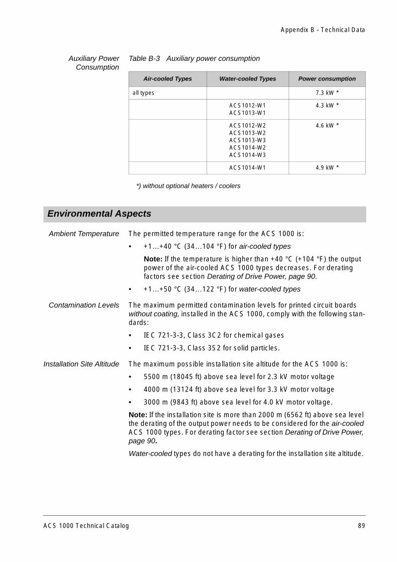
Extended AmbientTemperature: 50 °C
Above 40 °C the converter output power must be derated by 1.5% per 1 °Cand filter capacitors, suitable for high operating temperatures, aresupplied.
Corrosion ProtectedBus Bars
For certain environmental conditions (e.g. salty air in combination withincreased ambient temperature and high humidity) corrosion protectedbus bars can be chosen instead of the standard type. This choice is rele-vant for all power and grounding bus bars of the converter.
Coated PCBs For certain environmental conditions (e.g. salty air in combination withincreased ambient temperature and high humidity) the printed circuitboards (PCBs) can be ordered with a special varnish.
Converter Enclosure The standard IP classes of the converter enclosures are given in AppendixA - Installation Guidelines.
The following IP ratings are optional:
• IP22, IP31, IP32 and IP42 (for air-cooled converters)
• IP54 (for water-cooled converters)
Door Interlocking The ACS 1000 is equipped with an electromechanical door interlockingsystem as standard.
Alternative optional interlocking:
• Kirk key interlocking
If this option is required, contact your ABB representative.
Cabinet Color The standard color for the ACS 1000 converter is RAL 7035, “Light Grey”.Other RAL colors are available optionally and must be specified explicitlywhen ordered.
Cabinet Paint Finish The standard converter has painted front doors. Optionally, the entirecabinet exterior is available with painted surfaces (see also CabinetColor).
Split Cabinet The water-cooled ACS 1000 can be delivered with a shipping split for easytransportation. All materials necessary for joining the two parts aresupplied with the drive.
7.1 Environmental Conditions
7.2 Converter Enclosure
ACS 1000 Technical Catalog 51
Chapter 7 - Options
Extended GroundingBusbar
The standard grounding busbar which is located in the power cabletermination section of the ACS 1000 can be an extended throughout themedium voltage sections of the ACS 1000.
Input Bridges The following input rectifier bridges are available:
• 12-pulse diode rectifier (standard)
This type is sufficient for most network conditions to fulfill the networkharmonic requirements according to IEEE 519-1992.
It is the ideal solution for a small converter footprint and if an outdoortransformer can be used.
• 24-pulse diode rectifier with integrated or external transformerconfiguration
This type is recommended if superior network behavior is required.
The 24-pulse diode rectifier is applicable if outdoor transformers arenot required. In this case there is no need for an oil pit and no addi-tional cabling between transformer and converter is needed whichcan substantially reduce construction and installation costs.
Motor and TransformerProtection
Refer to Sections Extended Motor Monitoring Interface, page 53 andExtended Transformer Monitoring Interface, page 52.
Extended TransformerMonitoring Interface
In addition to the standard signal “Transformer Protection Trip” (wired intotripping loop) the signals according to Table 7-1 can be included optionallyin the signal interface between the transformer and the ACS 1000.
Note: This option requires the IOEC 3 board. The option is standard forwater-cooled converters (see Chapter 4 - User Interfaces, I/O Signals:transformer, page 28).
7.3 Input Section
Table 7-1 I/O signals for extended transformer monitoring
Type Signal Name Remarks
DI OIL LEVEL ALARM Transformer oil level alarmindication
DI OIL TEMP ALARM, or
TRAFO WDG TEMP ALARM
Transformer oil temperature alarmindication
Transformer winding temperaturealarm indication
DI /OIL TEMP TRIP, or
/TRAFO WDG TEMP TRIP
Transformer oil temperature tripindicationTransformer winding temperaturetrip indication
52 ACS 1000 Technical Catalog
Chapter 7 - Options
The analog input "Oil Temperature" is suitable for an actual value in therange of 0..20 mA / 4..20 mA (or 0..10 V / 2..10 V) and can be usedinstead of the digital temperature alarm and trip inputs. The analog signalis monitored by the ACS 1000 for alarm or trip levels.
Line UnbalanceProtection Relay
A signal from a line unbalance protection relay can be monitored by wiringit into the tripping loop of the ACS 1000. If the signal is low the main circuitbreaker is tripped immediately.
Common Mode Choke This option is needed if the cable length between the converter trans-former and the ACS 1000 exceeds the following limits:
• 30 m (98 ft) for ACS 1000, 12-pulse versions and
• 20 m (66 ft) for ACS 1000, 24-pulse versions.
If the cables are longer than the limits below, the ABB representativeshould be contacted:
• 200 m (656 ft) for ACS 1000, 12-pulse versions and
• 150 m (492 ft) for ACS 1000, 24-pulse versions.
The DC link common mode choke functions like a transformer. Togetherwith the common mode damping resistor it provides damping of thecommon mode voltages and limits the common mode currents experi-enced by the main power transformer and transformer secondary cables.
Extended MotorMonitoring Interface
In addition to the standard signal “Motor Protection Trip” (wired into trip-ping loop) the signals according to Table 7-2 can be included optionally inthe signal interface between the motor and the ACS 1000.
Note: This option requires the IOEC 3 board. The option is standard forwater-cooled converters (see Chapter 4 - User Interfaces, I/O Signals:motor, page 29),
DI BUCHHOLZ ALARM Transformer alarm indication fromBuchholz relay
DI /BUCHHOLZ TRIP Transformer trip indication fromBuchholz relay
AI OIL TEMP, or
TRAFO WDG TEMP
Temperature measurement oftransformer oilTemperature measurement oftransformer winding
Table 7-1 I/O signals for extended transformer monitoring (continued)
Type Signal Name Remarks
7.4 Motor Side
ACS 1000 Technical Catalog 53
Chapter 7 - Options
The analog inputs are suitable for actual values in the range of 0..20 mA /4..20 mA (or 0..10 V / 2..10 V) and are monitored by the ACS 1000 foralarm and trip levels.
Ex-Zone SignalInterface for Motor
Measurements (ZenerBarriers)
For motor installations in hazardous areas (Ex-Zone) all interface signalsfrom the motor have to be connected to Zener Barriers mounted in theconverter. This applies to the winding temperature and bearingtemperature measurements as well as to all digital signals e.g. externalmotor protection alarm and trip and external overspeed trip.
If this option is required, contact your ABB representative.
Pulse EncoderInterface Module
The Module allows a pulse encoder to be connected to the ACS 1000. Apulse encoder is advantageous in applications where the flying startfunction is used. The actual frequency of a rotating motor can be detectedfaster and rapid start-up by the converter can be achieved. It is alsorecommended if a highly accurate read-out of the speed is required.
Another application for a pulse encoder would be for motors running atspeeds below 5 Hz for longer periods.
The requirements for a pulse encoder are as follows:
• Supply voltage 12 VDC or 24 VDC (supplied by the module)
• Single ended or differential connection can be used
• Available signal channels: A, A inverted, B (90° electr. phase shift toA), B inverted (Z (zero channel), Z inverted - optional)
Table 7-2 I/O signals for extended motor monitoring
Type Signal Name Remarks
DI EXT MOT PROT ALARM (External) motor protection alarmindication
DI MOT COOLING ALARM (External) motor cooling alarmindication
DI /MOT COOLING TRIP (External) motor cooling tripindication
DI VIBRATION SV ALARM Motor vibration alarm indication
DI /VIBRATION SV TRIP Motor vibration trip indication
DI /OVERSPEED TRIP Motor overspeed trip (included inhardwired tripping loop)
AI BRG TEMP DE Motor bearing temperature ofdriven end
AI BRG TEMP NDE Motor bearing temperature of non-driven end
54 ACS 1000 Technical Catalog
Chapter 7 - Options
• The encoder should provide 2n pulses/revolution. The recommendedpulse train is 2048 pulses/revolution. Maximum signal frequencyshould not exceed 100 kHz.
The module is fed from the ACS 1000 internal control power supply.
Increased OutputFrequency
The ACS 1000 can be ordered with an increased output frequency of82.5 Hz as a maximum. This option requires an optimized sine filterconfiguration.
Braking Chopper Effective motor braking and short deceleration times can be achieved byusing resistor braking. For resistor braking, the ACS 1000 converter mustbe equipped with a braking chopper and a braking resistor.
Braking choppers are available for all ACS 1000 types. The choppers canbe ordered factory-installed or as add-on kits.
The operation of the braking chopper is controlled by the ACS 1000control system. The braking chopper hardware is located in an additionalcabinet.
The input currents of the braking chopper are monitored for overcurrentand unbalance in order to detect any defective component in the circuit. Incase a short circuit or an unsymmetry in the braking chopper is detecteda converter trip is initiated.
Braking chopper and braking resistors are each monitored forovertemperature by means of thermal models. Alarm and trip levels aredetermined and set during commissioning.
For more information about braking chopper and braking resistor, see theresistor specification or contact your ABB representative.
Braking Resistor The braking resistor has to be specified individually for eachproject by ABB Industrie AG. For further information contact your ABBrepresentative.
Circuit Breaker forMotor Space Heater
A motor space heater can be connected directly to a single-phase auxiliarypower circuit breaker, installed in the converter cabinet. Based on thepower rating of the heater, one of the circuit breaker sizes as indicated inTable 7-3 can be used.
ACS 1000 Technical Catalog 55
Chapter 7 - Options
Motor Starter for MotorCooling Fan / Pump
A motor cooling fan or pump can also be connected directly to an auxiliarymotor starter installed in the converter. Based on the power rating of thecooling fan or pump, one of the following motor starter sizes can bechosen:
Redundant CoolingFan (Air-cooled
ACS 1000)
The redundant cooling fan is an option intended for applications whereenhanced reliability of the installation is required.
The redundant fan unit is supplied as a separate unit to be mounted on topof the ACS 1000 converter. If delivered together with the ACS 1000, bothfans are already mounted in the unit. As add-on kit, only the redundant fanis supplied and the standard fan must be transferred from the convertercabinet to the redundant fan unit.
Table 7-3 Power ratings for different circuit breaker sizes
Auxiliary Voltage (single phase)
Circuit BreakerRating
120 V 240 V 400 V
0.5 A 60 W 120 W 200 W
1.0 A 120 W 240 W 400 W
2.0 A 240 W 480 W 800 W
3.0 A 360 W 720 W 1200 W
4.0 A 480 W 960 W 1600 W
5.0 A 600 W 1200 W 2000 W
6.0 A 720 W 1440 W 2400 W
10.0 A 1200 W 2400 W 4000 W
Table 7-4 Power ratings for different starter sizes
Auxiliary Voltage (three phase)
OverloadCurrent Rating
400 V 480 V 575 V
2.5 - 4.0 A 750 W - 1500 W(1.0 - 2.0 hp)
1100 W - 2000 W(1.5 - 2.7 hp)
1200 W - 2600 W(1.6 - 3.5 hp)
4.0 - 6.3 A 1500 W - 2200 W(2.0 - 3.0 hp)
2000 W - 3000 W(2.7 - 4.0 hp)
2600 W - 3600 W(3.5 - 4.8 hp)
6.3 - 10.0 A 2200 W - 4000 W(3.0 - 5.4 hp)
3000 W - 4000 W(4.0 - 5.4 hp)
3600 W - 6000 W(4.8 - 8.0 hp)
7.5 Converter Cooling
56 ACS 1000 Technical Catalog
Chapter 7 - Options
With this option continuous operation of the drive is guaranteed even ifone fan fails. Switch-over from the faulty to the stand-by device takesplace automatically. To replace the faulty unit the converter must bestopped. The replacement of a fan takes about 30 minutes.
Figure 7-1 Standard cooling fan unit
Figure 7-2 Redundant cooling fan unit (functional principle)
If this option is ordered the derating of the drive output power needs to beconsidered (see Appendix B - Technical Data, Environmental Aspects,page 89).
Redundant CoolingFan (Water-cooled
ACS 1000)
The water-cooled ACS 1000 can be ordered with a redundant cooling fan,if continuous operation is required in case a fan fails.
The redundant fan unit is supplied as a separate unit and is mounted ontop of the ACS 1000. If the redundant fan unit is ordered and deliveredtogether with the ACS 1000, the cut-outs on the roof and the mountingholes are already prepared. If the redundant fan is purchased separately,the roof cut-outs and the mounting holes have to be prepared on side.
Redundant CoolingPump (Water-cooled
ACS 1000)
The water-cooled ACS 1000 can be equipped with a second pump [P2] inthe cooling water circuit. This option is needed when continuous operationof the drive is required in case of a pump failure in the cooling unit. Theredundant pump is installed in the cooling unit of the ACS 1000.
Three-way Valve(Water-cooled
ACS 1000)
The cooling unit of the ACS 1000 can be ordered with a three-way valve[B14] in the raw water circuit. This option is recommended, if the raw waterflow must be kept at a constant rate. If the cooling unit is equipped with athree-way valve, the water-to-water heat exchanger [E1] is bypassed and
Control Box Rectifier Inverter
Control Box Rectifier Inverter
Air Duct
ACS 1000 Technical Catalog 57
Chapter 7 - Options
the total raw water flow is kept constant even if the water flow in the heatexchanger varies.
Cooling Unit (Water-cooled ACS 1000)
From the cooling water circuit below the interface connections towards theACS 1000 and the raw water supply can be seen. The components shownare part of the ACS 1000 cooling unit.
Figure 7-3 Cooling unit of the water-cooled ACS 1000
Space Heater forTropicalized Version
A space heater is typically required in places/countries with high ambienthumidity. It is switched on automatically when the converter is not inoperation in order to prevent condensation.
The heater consists of several heating elements with a rated power of100 W each.
Monitored Air Filter(Air-cooled ACS 1000)
The air-cooled ACS 1000 can be supplied with air filter mats which have afiner mesh than the standard air filter mat. There are filter mats availablewith a 10 µm and a 12 µm fine mesh.
The optional air filter mats should be selected if the air contamination levelexceeds IEC 721-3-3, Class 3C2 (for chemical gases) or IEC 721-3-3,Class 3S1 (for solid particles).
Air filter mats with finer mesh are monitored by measuring the pressuredifference across the filter. An alarm is displayed if the filter is clogged.
The filter mat which is mounted at the converter air intake can be changedwhile the converter is in operation.
C2
V13
L
CA
V11
M
V1 V3
V2 V4
E1
P1
P2
M
5 l/min
V14
12
PA
130 l/min
8 PA
TI
B13
QI
B12
PI
B11
V5
V81V80
S1
water to waterheat
exchanger
E2
B14
M
V82
24 l/
min
raw water inletnipple 33 mm
raw water outletnipple 33 mm
from converternipple 40 mm
to converternipple
ACS 1000 CABINET
COOLING UNIT
PressureAI 1.3
ConductivityAI 1.4
TemperatureAI 1.2
controlled by:DO 3.3DO 3.4
12 PA
12
PAOPTION
OPTION
Z2 (microfilter)
C1
Z1 (strainer)
Valve identification:
open (normal operation)
closed (normal operation)
Non-return valve
M
Control valve
B10
M11
M12
air to waterheatexchanger
make-up waterISO-R1/2
expansionvessel
ion exchangervessel
58 ACS 1000 Technical Catalog
Chapter 7 - Options
If the ACS 1000 is ordered with an air filter with finer mesh the derating ofthe drive output power needs to be considered (see Appendix B - Tech-nical Data, Environmental Aspects, page 89)
Synchronized Bypass The synchronized bypass (Figure 7-4) allows for automatic synchroniza-tion of a motor with the line after a soft start. Two versions are available:
• synchronized bypass for 1 motor
• synchronized bypass for up to 4 motors.
The bypass cabinet which is attached to the left hand side of theACS 1000 houses the following control hardware:
• the interface for external commands and feedback signals
• the signal interface(s) for the control of motor and bypass breakers
• the control unit for synchronizing and switching coordination
• the optional voltage measuring equipment.
For dimensions and weight of the bypass cabinet see Table C-4 Dimen-sions and weights of the ACS 1000 and optional equipment.
Note:The bypass switchgear is not included in the scope of this option.
Note:The ACS 1000 does not support manual or automatic bypassfunctions. All bypass related interlocks and the controls for the bypassswitches have to be realized externally to the drive. Only an outputdisconnector switch can be monitored via digital inputs, if IOEC 4 board isinstalled. These inputs are used to interlock the drive.
7.6 Converter Isolators and Bypass
ACS 1000 Technical Catalog 59
Chapter 7 - Options
Figure 7-4 Synchronized bypass, single line diagram
Input Isolator Used in addition to the main circuit breaker, the input isolator provides avisible break between the transformer and the rectifier section when theinput isolator is in the open position.
The input isolator is located in an additional cabinet next to the converter.
If this option is required, contact your ABB representative.
Output Isolator The output isolator is normally used in combination with a converterbypass and provides the possibility to isolate the converter visibly from themotor.
The output isolator is located in an additional cabinet next to the converter.
If this option is required, contact your ABB representative.
=
=
MCB Transformer12 PulseRectifier
Three LevelInverter
ACS1000 Frequency ConverterOutputFilter
Sm1
ACS 1000 Control
SynchronizedBypassControls
U2
Transformer 1MCB 1
(if necessary)
(if necessary)
Mains Supply
Mains Supply
MCB 2 Transformer 2
U11
Sbp1
Sbp2
Sm2
U12
3-PhM1
M23-Ph
60 ACS 1000 Technical Catalog
Chapter 7 - Options
Fieldbus AdapterModules
A fieldbus module may be used for controlling and monitoring theconverter instead of using conventional hard-wired I/Os.
There are several fieldbus adapter modules available for the ACS 1000:
• Profibus DP
• Profibus FMS
• Modbus
• Modbus+
• Allen-Bradley Device Net
• ABB Advant Fieldbus 100
• ABB Procontic CS31
• Interbus S
The fieldbus is connected to the adapter module via a twisted pair bus(RS 485) or via BNC-connectors (for ABB AF100). The adaptercommunicates with the ACS 1000 control board via a fast (4 Mbit/s)Duplex Fiber Optic Link.
All fieldbus modules require 24 VDC power. In all cases power is suppliedby the ACS 1000 internal control power supply (EPS).
Spare Terminals As an option, 30 spare terminals can be provided. These terminals are notwired up. A higher number of spare terminals is available on request.
DriveWindow DriveWindow offers several advanced, yet easy-to-use tools forcommissioning and control of the ACS 1000.
• The parameter and signal tool with a full set of device specific dataeither in online or offline mode to check, study and change theparameters
• The monitor tool as a graphic interface for monitoring digital andanalog signals
• The data logger as a versatile way of tracing fast and accurate events
• The fault logger displaying a fault history
• The application tools presenting the pin values in order to debugapplication software and force constants
7.7 Auxiliary & Control Interfaces
7.8 PC Tools
ACS 1000 Technical Catalog 61
Chapter 7 - Options
With its component structure, enhanced flexibility is achieved to allowworking with several different types of products through different targetand communication drivers (The look and feel of the DriveWindowprogram remains the same even when the product changes).
DriveSupport The DriveSupport tool offers an advanced level of servicing, maintainingand trouble shooting of a drive system. Versatile features are provided for:
• Diagnosing faults and warnings
• Testing and verifying possible causes of faults
• Locating of faulty components
• Performing step-by step replacement procedures
• Recording maintenance activities.
The DriveSupport works on-line together with the DriveWindow tool.
62 ACS 1000 Technical Catalog
Chapter 8 - Selecting the Drive System
The excellent performance of the ACS 1000 makes it suitable for mostvariable speed drive applications.
In order to dimension and configure an ACS 1000 drive system, the drivenload has to be clearly specified and an appropriate motor must beselected. The driven load together with the selected motor basicallydetermines the size of the ACS 1000 as well as the size of the requiredconverter input transformer.
8.2.1 Main Circuit Breaker Control
The Main Circuit Breaker (MCB) must be controlled exclusively by theACS 1000. This means that a closing request or command is sent from acustomer’s local or remote control station to the ACS 1000. The actualclosing command is then released from the converter to the MCB.
The closing command from the converter to the MCB (duration can be pre-set) can be a continuous signal or a single pulse, which is reset as soonas the status feedback MCB IS CLOSED has been received from theswitchgear. If this status feedback has not arrived after a pre-set time, theclosing command is reset and a trip of the MCB is initiated.
The MCB is opened by :
• an MCB OPEN command, either given from the push button on theACS 1000 or from a remote control station via digital inputs orthrough a fieldbus adapter
• the hardwired tripping loop (see Tripping Loop, page 64).
The opening command from the converter to the MCB - pulse or steadystate signal - is reset as soon as the status feedback MCB IS OPEN hasbeen received. If the feedback signal has not arrived after a preset timethe command MCB ORDER TRIP is initiated to open the MCB.
The MCB ORDER TRIP is a steady state true signal. When in low statusit directly opens the MCB.
MCB Control Fault All opening and closing commands to the MCB are monitored for time-outAn alarm or fault message comes up on the display of the CDP 312 controlpanel if there is something wrong in connection with the control of theMCB.
8.1 Overview
8.2 Main Circuit Breaker
ACS 1000 Technical Catalog 63
Chapter 8 - Selecting the Drive System
8.2.2 Tripping Loop
General The tripping loop is a hardwired control circuit provided to trip the MCBdirectly either via the tripping coil or via the opening coil. Depending onwhich coil is available, the tripping coil or the opening coil has to beconnected to the tripping loop.
Signals from customer devices can (but do not have to) be wired into thisloop. Each of these signals is monitored by a digital input. These signalscan be connected to a terminal strip in the control section of theACS 1000. If one or several of the signals are not used a jumper must beput across the corresponding terminals.
Figure 8-1 Tripping loop: principle diagram
3
2
4
56
8
910
11
1X 300
12
13
emergency off
transformer protection trip
motor protection trip
overspeed trip
supply voltage unbalance trip
MCBtripping coil
jumper when signal is not used
(one or more emergency offconnected in series)
22...250 VAC22...150 VDCcontrol voltage
provided by customer
optional IOEC board 3 required
*
*
*
*
*
*
Control section of ACS 1000Customer side
64 ACS 1000 Technical Catalog
Chapter 8 - Selecting the Drive System
ACS 1000 TrippingLoop Signals
The following ACS 1000 contacts are wired to the tripping loop:
• the digital output "MCB ORDER TRIP"
• the emergency-off button on the ACS 1000 front door.
The digital output "MCB ORDER TRIP" is initiated:
• if the grounding isolator is closed or not not completely opened
• after an off command and there is no feedback signal within a pro-grammable time lapse
• when switching off the main circuit breaker and a signal discrepancybetween off command and feedback signal is detected
• by main circuit interface board of the ACS 1000 in case of a trip.
Customer Signals The following signals from customer devices can (but do not need to) bewired to the tripping loop terminals:
• external emergency-off
• transformer protection trip
• motor protection trip
• overspeed trip
• supply voltage unbalance.
The following signals require the optional IOEC 3 board:
• overspeed trip
• supply voltage unbalance.
8.2.3 Main Circuit Breaker Features
General Requirementsfor MCB
The MCB has to be specified according to the rated primary voltage andcurrent of the converter transformer. It should also meet the specific driverequirements (some items require proper coordination with the instrumen-tation and protection equipment). The MCB must be capable:
• to connect and maintain nominal load currents and clear short-circuitcurrents
• to tolerate the transformer inrush current without tripping
• to clear transformer secondary short circuits within 250 ms (the timeincludes the pick-up time of the protection relay and the opening timeof the MCB)
• close in response to a close command
• open within 160 ms in response to an open command (signal activewhen high)
• open within 160 ms in response to a trip command (signal activewhen low)
ACS 1000 Technical Catalog 65
Chapter 8 - Selecting the Drive System
• provide a status output which indicates MCB closed
• provide a status output which indicates MCB open
• provide a status output which indicates MCB not available (vacuumcircuit breaker in test position or vacuum controller disconnect switchin open position).
Types of MCBs The following types of MCBs can be used:
• vacuum or gas insulated (SF6) circuit breakers
• load disconnectors with fuse
• vacuum or gas insulated (SF6) controllers / medium voltage starters.
MCB Control SignalInterface
A possible signal interface between the ACS 1000 and a vacuumcontroller or vacuum circuit breaker is indicated in the schematic diagramsbelow.
Figure 8-2 Connection scheme with vacuum circuit breaker
52
ACS 1000
5051
51N
M
CB
no
t av
aila
ble
MC
B o
pen
M
CB
clo
sed
clo
se c
om
man
d
op
en c
om
man
d
AC time residuaovercurrent rela
instantaneous / AC timovercurrent relay
trip signals
vacuum circuit breaker
trip
ping
loopl
y
e
66 ACS 1000 Technical Catalog
Chapter 8 - Selecting the Drive System
Figure 8-3 Connection scheme with vacuum controller
MCB Instrumentationand Protection
Equipment
Appropriate current transformers and protection relaying must be providedto protect transformer and transformer primary cables. The intendedapproach for protection is shown in Figure 8-4. As shown in the figure theprotection can be considered to consist of three areas. The first areaidentified as Transformer Primary Fault Protection is an instantaneous triparea that protects against short circuits in the transformer primarywindings or in the cables supplying the transformer primary. The lowerlevel of the trip threshold should be adjusted high enough to insure thatnuisance tripping does not occur due to transformer inrush currents. Thesecond area identified as Transformer Secondary Fault Protection is ashort delay trip area that protects against short circuits in the transformersecondary windings, the cables from the transformer secondaries to theACS 1000, or in the input rectifier stages of the ACS 1000. The short timedelay provided should be adjustable and should be set long enough toinsure that the protection does not trip due to transformer inrush current.The trip level should be adjusted low enough to insure that tripping willoccur within 100 ms (including MCB delay time) even if transformers withhigh input impedance are used. The final area identified as OverloadProtection should provide long term overload protection with an inversetime characteristic. This area is intended to protect the transformer andcables from long term overload conditions.
ACS 1000
5051
51N
MC
B n
ot
avai
lab
le
MC
B o
pen
M
CB
clo
sed
clo
se c
om
man
d
op
en c
om
man
d
vacuum contactortrip signals
AC time residuaovercurrent rela
instantaneous / AC timovercurrent relay
non load-break disconnector
fast acting current lim it ing fuse
l
e
y
trip
ping
loop
ACS 1000 Technical Catalog 67
Chapter 8 - Selecting the Drive System
The protection described can be provided with individual protection relaysor with a single microprocessor based unit. Required current transformersshould be sized in accordance with the rated current levels of thetransformer. Basic protection configuration and connection should be aspreviously shown in Figure 8-2 and Figure 8-3.
Figure 8-4 Sample protection scheme
All ACS 1000 converters must be supplied from an isolation transformerwith multiple phase-shifted secondary windings, designed in accordancewith the pulse number of the input bridge. For 12-pulse systems thesecondary side of the transformer has one star and one delta winding.This creates the 30° phase shift between the two 3-phase secondarywindings, that is necessary to facilitate 12-pulse input bridge operation.The secondary windings of transformers for ACS 1000 converters with 24-pulse rectifier bridge are to be designed to provide a 15° phase shift.
A second purpose of the transformer is to provide sufficient impedance tolimit the line harmonics to acceptable levels.
The transformer may be an oil-immersed or a dry type. Based oninstallation requirements of the application, the transformer may belocated remote from the ACS 1000 drive equipment or nearby, evenintegration into the drive is possible. For requirements regarding themaximum cable length between transformer and ACS 1000 see AppendixB - Technical Data .
The transformer may be supplied from ABB or alternatively from a thirdparty supplier in accordance with the specifications provided by ABB. Thedesign of the transformer must take into account site-specific lineconditions (voltage, short circuit capacity, existing harmonics, etc.) toinsure compliance with harmonic standards invoked by the specifications.Transformer quality is critical with respect to effecting proper limitation ofharmonic currents and voltages.
10 ms 200 ms 1 s 10 s 100 s
x 1
x 10
x 20 Transformer primary fault protection
Transformer secondary fault protection
Overload protection
Adjustable time delay
8.3 Converter Input Transformer Selection
68 ACS 1000 Technical Catalog
Chapter 8 - Selecting the Drive System
When determining the power rating of the transformer, power andefficiency of the motor, power factor and efficiency of the ACS 1000converter and harmonic loading of the transformer must all be considered.
For selecting an appropriate ABB ACS 1000 transformer or for specifiyinga generic transformer, please contact your ABB representative.
The rating tables for selecting the ACS 1000 can be found in this chapter.
In general the ACS 1000 converter is selected according to the ratedmotor power. The rated output current of the ACS 1000 should bechecked to insure that it is higher than or equal to the rated motor current.
If a motor with 6 or more poles is used, the nominal motor current usuallyincreases as compared to a motor with fewer poles. This may result in adifferent output filter configuration (see ACS 1000 Output Filter below). Insuch cases, please contact your ABB representative for further assistancebefore making a final drive selection.
When determining the appropriate size of the ACS 1000 converter for aparticular application the following factors need to be considered:
• ambient temperature
• temperature of the cooling media
• installation site altitude
• frostproofing of the cooling water
• the presence of a redundant cooling fan
• type of air filter.
Please refer to Appendix B - Technical Data for details on environmentalaspects.
8.4.1 ACS 1000 Output Filter
The standard ACS 1000 output filter is appropriate for 2 to 6-pole motors.For higher numbers of poles a different filter configuration is sometimesneeded. The modular and flexible filter design allows the ACS 1000 to beconfigured for 2 to 20-pole motors (and even higher numbers of poles). Todetermine the appropriate ACS 1000 configuration please contact yourABB representative.
8.4.2 Non Quadratic Load Applications
For constant torque or constant power applications a high overloadability(start-up torque) is usually required. This overloadability, together withpossibly needed derating for low speed operation, requires someadditional calculations for drive selection. To determine the appropriateACS 1000 please contact your ABB representative.
8.4 Selection of the ACS 1000 Converter
ACS 1000 Technical Catalog 69
Chapter 8 - Selecting the Drive System
8.4.3 ACS 1000 Selection Tables
Selection Table forAir / Water-cooled
ACS 1000 with2.3 kV Motors
ACS 1000 rated for 2.3 kV have output ratings based on horsepower (HP).Equivalent output ratings in kilowatt (kW) are approximate and listed forreference only.
Note: The load capacity (current and power) decreases if the environ-mental conditions at site do not comply with the limits given in Appendix B- Technical Data, Environmental Aspects, page 89. The resulting deratingfactors are specified in Appendix B - Technical Data, Derating of DrivePower, page 90.
*, ** See note at end of this Section on page 72
Table 8-1 ACS 1000 ratings for 2.3 kV motors, 50 Hz and 60 Hz supply (12/24-pulse)
MotorVoltage
(kV)Converter Type*
Type ofCooling
Max. cont.Converter
Power(kVA)
RatedMotor
Power**(HP)
Equival.Motor
Power**(kW)
RatedOutputCurrent
(A)
FrameSize
2.3 ACS10x2-A1-A0-00 Air 400 400 _ 100 A1
2.3 ACS10x2-A1-B0-00 Air 400 450 315 100 A1
2.3 ACS10x2-A1-C0-00 Air 450 500 355 113 A1
2.3 ACS10x2-A1-D0-00 Air 550 600 450 138 A1
2.3 ACS10x2-A1-E0-00 Air 650 700 500 163 A1
2.3 ACS10x2-A1-F0-00 Air 750 800 560 188 A1
2.3 ACS10x2-A1-G0-00 Air 800 900 630 201 A1
2.3 ACS10x2-A1-H0-00 Air 900 1000 710 226 A1
2.3 ACS10x2-A2-J0-00 Air 1150 1250 900 289 A2
2.3 ACS10x2-A2-K0-00 Air 1350 1500 1120 339 A2
2.3 ACS10x2-A3-L0-00 Air 1550 1750 1250 389 A3
2.3 ACS10x2-A3-M0-00 Air 1800 2000 1400 452 A3
2.3 ACS10x2-A3-N0-00 Air 2000 2250 1600 502 A3
2.3 ACS10x2-W1-P0-00 Water 2300 2500 1800 577 W1
2.3 ACS10x2-W1-Q0-00 Water 2700 3000 2250 678 W1
2.3 ACS10x2-W2-R0-00 Water 3100 3500 2500 778 W2
2.3 ACS10x2-W2-S0-00 Water 3600 4000 2800 904 W2
70 ACS 1000 Technical Catalog
Chapter 8 - Selecting the Drive System
Selection Table forAir / Water-cooled
ACS 1000 with3.3 kV Motors
ACS 1000 rated for 3.3 kV have output ratings based on kilowatt (kW).Equivalent output ratings in horsepower (HP) are approximate and listedfor reference only.
*, ** See note at end of this Section on page 72
Table 8-2 ACS 1000 ratings for 3.3 kV motors, 50 Hz and 60 Hz supply (12/24-pulse)
MotorVoltage
(kV)Converter Type*
Type ofCooling
Max. cont.Converter
Power(kVA)
RatedMotor
Power**(HP)
Equival.Motor
Power**(kW)
RatedOutputCurrent
(A)
FrameSize
3.3 ACS10x3-A1-A0-00 Air 400 450 315 70 A1
3.3 ACS10x3-A1-B0-00 Air 450 500 355 79 A1
3.3 ACS10x3-A1-C0-00 Air 500 550 400 87 A1
3.3 ACS10x3-A1-D0-00 Air 550 600 450 96 A1
3.3 ACS10x3-A1-E0-00 Air 600 700 500 105 A1
3.3 ACS10x3-A1-F0-00 Air 700 750 560 122 A1
3.3 ACS10x3-A1-G0-00 Air 750 800 630 131 A1
3.3 ACS10x3-A1-H0-00 Air 850 900 710 149 A1
3.3 ACS10x3-A2-J0-00 Air 950 1000 800 166 A2
3.3 ACS10x3-A2-K0-00 Air 1100 1250 900 192 A2
3.3 ACS10x3-A2-L0-00 Air 1200 1350 1000 210 A2
3.3 ACS10x3-A2-M0-00 Air 1350 1500 1120 236 A2
3.3 ACS10x3-A2-N0-00 Air 1500 1650 1250 262 A2
3.3 ACS10x3-A2-P0-00 Air 1700 1750 1400 297 A2
3.3 ACS10x3-A3-Q0-00 Air 1900 2000 1600 332 A3
3.3 ACS10x3-A3-R0-00 Air 2150 2250 1800 376 A3
3.3 ACS10x3-W1-S0-00 Water 2400 2500 2000 420 W1
3.3 ACS10x3-W1-T0-00 Water 2700 3000 2250 472 W1
3.3 ACS10x3-W1-U0-00 Water 3000 3350 2500 525 W1
3.3 ACS10x3-W2-V0-00 Water 3350 3500 2800 586 W2
3.3 ACS10x3-W2-W0-00 Water 3750 4000 3150 656 W2
3.3 ACS10x3-W2-X0-00 Water 4250 4500 3550 744 W2
3.3 ACS10x3-W3-Y0-00 Water 4750 5000 4000 831 W3
3.3 ACS10x3-W3-Z0-00 Water 5350 6000 4500 936 W3
3.3 ACS10x3-W3-10-00 Water 5950 6700 5000 1041 W3
ACS 1000 Technical Catalog 71
Chapter 8 - Selecting the Drive System
Selection Table forAir / Water-cooled
ACS 1000 with4.0 kV Motors
ACS 1000 rated for 4.0 kV have output ratings based on horsepower (HP).Equivalent output ratings in kilowatt (kW) are approximate and are listedfor reference only.
** The power ratings apply to typical 4 pole motors. For those motors theACS 1000 has a built-in overloadability of 10%. When selecting theACS 1000 it should be observed that the rated current of the ACS 1000must be higher than or equal to the rated motor current in order toachieve the rated motor power given in the table.
Table 8-3 ACS 1000 ratings for 4.0 kV motors, 50 Hz and 60 Hz supply (12/24-pulse)
MotorVoltage
(kV)Converter Type*
Type ofCooling
Max. cont.Converter
Power(kVA)
RatedMotor
Power**(HP)
Equival.Motor
Power**(kW)
RatedOutputCurrent
(A)
FrameSize
4.0 ACS10x4-A1-A0-00 Air 400 400 _ 58 A1
4.0 ACS10x4-A1-B0-00 Air 400 450 315 58 A1
4.0 ACS10x4-A1-C0-00 Air 450 500 355 65 A1
4.0 ACS10x4-A1-D0-00 Air 550 600 450 79 A1
4.0 ACS10x4-A1-E0-00 Air 650 700 500 94 A1
4.0 ACS10x4-A1-F0-00 Air 750 800 560 108 A1
4.0 ACS10x4-A1-G0-00 Air 800 900 630 115 A1
4.0 ACS10x4-A1-H0-00 Air 900 1000 710 130 A1
4.0 ACS10x4-A2-J0-00 Air 1150 1250 900 166 A2
4.0 ACS10x4-A2-K0-00 Air 1350 1500 1120 195 A2
4.0 ACS10x4-A3-L0-00 Air 1550 1750 1250 224 A3
4.0 ACS10x4-A3-M0-00 Air 1800 2000 1400 260 A3
4.0 ACS10x4-A3-N0-00 Air 2000 2250 1600 289 A3
4.0 ACS10x4-W1-P0-00 Water 2300 2500 1800 332 W1
4.0 ACS10x4-W1-Q0-00 Water 2700 3000 2250 390 W1
4.0 ACS10x4-W2-R0-00 Water 3100 3500 2500 447 W2
4.0 ACS10x4-W2-S0-00 Water 3600 4000 2800 520 W2
4.0 ACS10x4-W2-T0-00 Water 4000 4500 3150 577 W2
4.0 ACS10x4-W2-U0-00 Water 4500 5000 3550 650 W2
4.0 ACS10x4-W3-V0-00 Water 4900 5500 4000 707 W3
4.0 ACS10x4-W3-W0-00 Water 5300 6000 4500 765 W3
4.0 ACS10x4-W3-X0-00 Water 5800 6700 5000 837 W3
72 ACS 1000 Technical Catalog
Chapter 8 - Selecting the Drive System
8.5.1 Load Capacity Curves
This chapter provides the necessary information regarding the selectioncriteria of the motor, to match the ACS 1000.
In the example below the rated frequency and the field weakening pointfor the motor are based on 50 Hz.
Figure 8-5 Load capacity curves
8.5 Motor Selection
Curve 1: Typical continous load capacity curve of an IEC34 self-ventilated motor, controlled by the ACS 1000.
Curve 2: Load capacity of the ACS 1000, rated for normal use (i.e.100% continous, 110% for 1 min. every 10 min.).
p = number of polesT = load torqueTN = rated motor torquen = speedf = output frequency of
ACS 1000
ACS 1000 Technical Catalog 73
Chapter 8 - Selecting the Drive System
8.5.2 Selection Criteria
Generally speaking the motor must be selected and sized as required bythe load. Supplying an additional power margin to compensate for PWMinverter operation is not required with the ACS 1000 due to its sinusoidaloutput waveform. After the motor has been selected (or if an existingmotor is being applied) the following parameters are relevant to select theconverter and the transformer:
• load characteristic (the most common characteristic is square torque;for other loads like constant torque or constant power applications,please contact your ABB representative)
• overloadability requirements
• motor voltage
• number of motor poles
• shaft power (nominal)
• shaft speed (nominal)
• rated current (nominal)
• motor efficiency
• motor power factor.
Special attention must be paid to the motor cooling in variable speedapplications. If the motor is self-ventilated, long-time operation at lowspeeds will usually require some derating to compensate for the reducedcooling.
Depending on the mechanical configuration of the motor, load, gear-boxand shaft there may be some critical speeds within the operating speedrange of the drive. The critical speeds have to be known and if they haveto be avoided the appropriate parameter settings have to be made.Special attention has to be paid to variable speed applications using two-pole motors, since there is usually a critical motor speed below its ratedspeed. For more information see Chapter 6 - Standard Functions, CriticalSpeed.
8.5.3 Retrofit
Due to its specific topology the ACS 1000 can supply standard mediumvoltage motors (existing or new) without applying thermal derating factors.In addition, due to its sinusoidal output waveform, standard mediumvoltage winding insulation is sufficient.
To avoid risk of bearing currents and related consequential damages, onemotor bearing should be insulated (the one at the non-driven shaft end).This is actually a typical accessory even for most direct on-line operatedmotors. If, nevertheless, such a bearing is not available (e.g. for olderexisting motors), a grounding brush can be installed on either shaft end.
74 ACS 1000 Technical Catalog
Chapter 8 - Selecting the Drive System
Although from an electrical point of view no restrictions exist for variablespeed operation with retrofit motors, attention should be paid to possiblemotor and load restrictions such as insufficient lubrication or reducedcooling at low speed, critical speed areas within the targeted operatingrange that need to be avoided, etc. Also the maximum (i.e. rated) speedof the motor should under no circumstances be increased withoutauthorization from the manufacturer of each component of the drive trainconcerned.
8.5.4 Torsional Excitation
Due to its sinusoidal output voltage and current waveforms and itssuperior control performance from DTC the ACS 1000 will not introduceany significant torsional excitations to the motor shaft. Therefore atorsional analysis for the sake of applying a frequency converter is notrequired for common applications and normal mechanical shaftarrangements.
ACS 1000 Technical Catalog 75
Chapter 8 - Selecting the Drive System
76 ACS 1000 Technical Catalog
Appendix A - Installation Guidelines
Ambient conditions may require to derate the drive due to the presence ofelevated air temperature, altitude, or cooling water temperature. Sufficientair flow must be available. Other ambient factors such as relative humidity,air contamination, shock and vibration must also be in compliance withstated maximum permissible levels.
See Appendix B - Technical Data for load capacity derating factors andother requirements related to ambient conditions.
Converter Enclosure The standard IP protection classes for the converter enclosure accordingto IEC 529 are:
• IP21 (for air-cooled converters)
• IP31 (for water-cooled converters).
Higher IP-protection classes for the converter enclosure are optional.Please refer to Chapter 7 - Options.
Space Requirements All units must be mounted in an upright position with adequate free spaceprovided in accordance with Table A-1.
Table A-1 Required free space in front and above converter
(The dimensions given are minimum values)
Notes:
1 Dimensions do not include space for cable entrywhich can be from top or from below.
2 Dimensions are above the blower hood or above theredundant fan unit.
3 This is a general recommendation to ensure properair flow.
Ambient Conditions
Mounting
Type ofCooling
Abovemm / (in.)
Belowmm / (in.)
Left / Rightmm / (in.)
Frontmm / (in.)
Backmm / (in.)
Air 500 (1)(2)(3)
(20")0 (1)
(0")0 (5)
(0")1000 (4)
(39.4")0 (6)
(0")
Water 0 / 700 (1)(2)
(0")/(27.6")0 (1)
(0")0 (5)
(0")1000 (4)
(39.4")0(0")
ACS 1000 Technical Catalog 77
Appendix A - Installation Guidelines
4 Dimensions indicate required door swing area. Addi-tional space may be needed to meet local installationregulations and requirements.
5 Dimensions do not include space for moving the cab-inet, nor for cable and water entries (which can befrom top or from below).
6 For service reasons a minimum clearance of 400 mm(15.75") is recommended but not required.
Figure A-1 ACS 1000 free space requirements
For cabinet dimensions refer to Appendix C - Dimensions and Weights.
Front view
Top view
1000 mm / 39.4 in.1000 mm / 39.4 in.
Air-cooled ACS 1000 Water-cooled ACS 1000
5 400 mm / 15.75 in.00 mm / 20 in.
78 ACS 1000 Technical Catalog
Appendix A - Installation Guidelines
The foundation plans for the ACS 1000 12-pulse, air and water-cooled,are given in Figure A-2 and Figure A-3.
Figure A-2 Foundation plan with position of anchoring holes: ACS 100012-pulse, air-cooled
Figure A-3 Foundation plan with position of anchoring holes: ACS 100012-pulse, water-cooled
2846
2856
800
37.5
78
78
20
12
802.52760/3260 *585.5
432
800
685
70181
38
20
50
12
1080.5
ACS 1000 Technical Catalog 79
Appendix A - Installation Guidelines
The cabinet should be fixed with anchor bolts and lock washers (recom-mended size M12, not part of supply) as shown in Figure A-4 below. Theanchor holes in the base mounting channels can be accessed through thecabinet.
Figure A-4 Cabinet mounting with bolts and lock washers
Floor Levelling andCable Ducts
• The ACS 1000 cabinet must be installed in upright position.
• The maximum allowable overall unevenness is ≤ 5 mm. If the floor isuneven, it must be levelled.
• The floor must be of non-flammable material, with smooth and non-abrasive surface, protected against humidity diffusion and able tosupport the weight of the converter (min. 1’000 kg/m2).
• Cable ducts must be of non-flammable material, with non-abrasivesurface and protected against humidity, dust and penetration ofanimals.
General
The connection from the mains supply to the ACS 1000 drive consists ofsix basic elements:
• Main circuit breaker / controller
• Instrumentation and protection equipment
• Transformer primary cables
• Transformer
• Transformer secondary cables
• Cable termination - ACS 1000.
Recommendations for the installation of each of these elements are givenbelow. All applicable manufacturer’s instructions and local regulationsmust be followed when installing this equipment. If any specific instruction
anchoring holes
Power Equipment Installation
80 ACS 1000 Technical Catalog
Appendix A - Installation Guidelines
as stated in this manual appears to be in conflict with the requirements,please contact your local ABB representative for further assistance.
For information regarding Main Circuit Breaker / Controller,Instrumentation and Protection Equipment refer to Chapter 6 - StandardFunctions and Chapter 8 - Selecting the Drive System.
Transformer Primary Cables
The cables from the Main Circuit Breaker (MCB) to the Transformerprimary side has no special requirements. It should carry a voltage ratingconsistent with the voltage present in the primary circuit. The ampacityrating should be consistent with the size of the transformer being suppliedand the protection settings of the protection equipment. Derating of cableampacity in accordance with maximum expected ambient temperature,raceway fill factors and any other factors required by local electrical codesshould be applied. Installation should be in compliance with standardindustrial practice for medium voltage equipment.
If required by local electrical code, an equipment safety ground wireshould be supplied either separately or by including it in the 3- core cable.The ampacity of this conductor should be in accordance with the code.
Transformer Secondary Cables
The cables from the transformer secondary windings to the ACS 1000main power input buses, are exposed to common mode voltages, resultingfrom normal inverter operation. For this reason it is necessary to usecables rated for insulation levels of 5 kV (phase to earth) or higher for alltransformer secondary connections, regardless of the transformersecondary voltage level (1327 V, 1903 V, or 2305 V). Cables rated for 5 kVare typically used in North America, in Europe cables rated for 6kV/10 kVare common.
In order to insure compliance with EMC requirements and to provide a lowimpedance, high frequency path through which the common modecurrents can flow, a shielded cable is recommended. Shields should beterminated and grounded at the shortest possible way at both cabletermination points. The ACS 1000 includes a vertical ground bus withinthe cable termination section in order to facilitate above requirement.
A non-shielded cable with a continuous corrugated aluminum armor maybe used as an alternative to the shielded cable described above. Steelwire armored or interlocked aluminum armored cable should not be used.Cable terminal ends with electrical contact all around its periphery to thearmor should be used to terminate the cable ends to the ground.
The ampacity rating of the cable should be in consistency with 125% of thetransformer nominal output current and the settings of the protectionequipment in order to allow for the harmonic content. Derating of cableampacity in accordance with maximum expected ambient temperature,raceway fill factors and any other factors required by local electrical codes
ACS 1000 Technical Catalog 81
Appendix A - Installation Guidelines
should be applied. Installation should be in compliance with standardindustrial practice for medium voltage equipment.
If required by local electrical code, an equipment safety ground wireshould be supplied separately. The ampacity of this conductor shall be inaccordance with the code.
For information regarding the maximum length of the transformersecondary cables see Appendix B - Technical Data.
Motor Cables
There are no special requirements to be considered for the motor cables.The maximum cable length is limited to 1000 m (3281 ft). A voltage ratingconsistent with the voltage present at the motor must be selected. Theampacity rating should be consistent with the size of the motor beingsupplied and the overload settings of the motor protection software.Derating of cable ampacity in accordance with maximum expectedambient temperature, raceway fill factors, and any other factors requiredby local electrical codes should be applied. Installation should comply withstandard industrial practice for medium voltage equipment.
Cable screening is not required for the motor cables, since the converteroutput voltage and current are sinusoidal. Therefore no measures againstcommon mode currents are needed.
If required by local electrical code an equipment safety ground wire shouldbe supplied separately. The ampacity of this conductor shall be in accor-dance with the code.
Motor cables are terminated within the ACS 1000 cabinet in the same wayas the transformer secondary cables (see Figure A-5).
Power Cable Dimensions
In order to determine the exact dimensions for a specific project, the actualsituation (method of installation, voltage drop due to cable length etc.) andlocal regulations must be considered. Refer also to the specificationssupplied by the power cable manufacturer.
Equipment Grounding
It is recommended that the ACS 1000 ground bus is connected to the plantground bus. The recommended cross-section of the ground connectiondepends on the motor cable cross-section.
Auxiliary Power Cables
A 3-phase cable without neutral connector is required for auxiliary powersupply. Type and ratings are to be selected according to local regulations.For ratings see also Appendix B - Technical Data.
82 ACS 1000 Technical Catalog
Appendix A - Installation Guidelines
Control Cables
Control cables should be in accordance with Table A-2. Cable shieldsshould be terminated on the ACS 1000 end only. Either single or multipletwisted pair cables may be used.
Table A-2 Control cable requirements
Cable Routing
Power Cables Routing of mains and motor cables must be carried out in compliance withthe local regulations and according to the specifications and recommen-dations of the cable manufacturer.
• For best EMC performance, shielded three phase cables arerecommended.
• If single phase cables are used, the cables with the three differentphases must be grouped close together to ensure best EMCperformance.
• Phase interchange must be accomplished according to localregulations.
• For high power ratings, a maximum of two cables per motor phasecan be accommodated by the gland plates of the ACS 1000.
• If the cross-section of the cable shielding is less than 50% of thecross-section of one phase, an additional grounding wire should belaid along the power cables to avoid excessive heat losses in the ca-ble shieldings. Please refer to the local regulations for further details.
Cable Termination Cables must be terminated with connectors according to the cable manu-facturer’s requirements.
Grounding Wire Routing of the grounding connection must comply with local regulations.
Control Cables Control cables should not be laid in parallel to the power cables. If thiscannot be avoided, a minimum distance of 30 cm (12 inches) must bemaintained between control and power cables.
Control and power cables should be crossed at an angle of 90°.
Signal Type General Cable TypeCross-Section
(I/O Termination)
Analog In Twisted pair(s) - Overall Shield 0.5 to 2.5 mm2 /AWG 20 to AWG 12
Analog Out Twisted pair(s) - Overall Shield 0.5 to 2.5 mm2 /AWG 20 to AWG 12
Digital In Twisted pair(s) 0.5 to 2.5 mm2 /AWG 20 to AWG 12
Digital Out Twisted pair(s) 0.5 to 2.5 mm2 /AWG 20 to AWG 12
ACS 1000 Technical Catalog 83
Appendix A - Installation Guidelines
ACS 1000 Cable Entry and Termination
Access to the power termination section of the ACS 1000 is via the controlcabinet, located on the left of the converter. A bolted access door islocated behind the control swing frame. Once the access door is openedall power terminations are readily available. As an aid to interfacing themain power connections, removable bus stubs are included.
Figure A-5 shows a typical example of how transformer and motor cablesare connected to the internal bus system of the ACS 1000.
Cables can be entered through the cabinet roof or from the bottom. If thecable entry is from below, the gland plates mounted on top of the cabletermination section must be relocated to the bottom and the bottom coverplate must be fixed to the top of the cabinet.
Figure A-5 Principle of power cable entry (water-cooled type)
Front viewSide view
Front sideof cabinet
2U1
2V1
2W1
U2
V2
W2
1U1
1V1
1W1
84 ACS 1000 Technical Catalog
Appendix A - Installation Guidelines
Transformer Connection Diagram for 12-pulse ACS 1000
Motor Connection Diagram for 12 / 24-pulse ACS 1000
Figure A-8 Typical 3-line motor connection diagram
ACS 1000
PE
FactoryGround U2 W2
V2
UV
W
PEFactoryGround
M
86 ACS 1000 Technical Catalog
Appendix B - Technical Data
Primary Side Voltage Any medium voltage level can be applied to the primary side of theconverter input transformer.
Secondary SideVoltage
Transformer secondary side / converter input voltages (no load) for12 / 24-pulse ACS 1000:
• 1327 VAC, ± 10% for 2.3 kV motors
• 1903 VAC, ± 10% for 3.3 kV motors
• 2305 VAC, ± 10% for 4.0 kV motors
Safe operation with reduced output power is possible down to -25%.
Phase Shift Phase shift between transformer secondary windings:
• 30° for 12-pulse ACS 1000
• 15° for 24-pulse ACS 1000
Frequency Range 50 / 60 Hz
Voltage Unbalance max. ± 2% (Umax - Umin ) / Uavg
Fundamental PowerFactor
cos ϕ1 > 0.97
Total Power Factor cos ϕT > 0.95
TransformerSecondary Cables
Depending on the presence of a Common Mode Choke (CMC) in theACS 1000, the maximum permitted length for the transformer secondarycables is as follows:
Table B-1 ACS 1000 without CMC
Transformer Connection / Converter Input
ACS 1000 Types Rectifier Type Max. cable length
Air-cooled 12-pulse 30 m (98 ft)
Water-cooled 12-pulse 30 m (98 ft)
Air-cooled 24-pulse 20 m (66 ft)
Water-cooled 24-pulse 20 m (66 ft)
ACS 1000 Technical Catalog 87
Appendix B - Technical Data
Table B-2 ACS 1000 with CMC
Nominal Voltage UNom: 2.3 kVAC, 3.3 kVAC, 4.0 kVAC
Operational Voltage UOut: 0…UNom, 3-phase, sinusoidal, symmetrical
Frequency 0...66 Hz for UNom = 2.3 kV, 3.3 kV and 4.0 kV
Frequency Resolution 0.01 Hz
Short Term OverloadCapacity
1 min/10 min: 110% of rated current
Field Weakening Point 45…66 Hz
Switching Frequency 1 kHz (3-level inverter, operating at 2 x 500 Hz)
Maximum Motor CableLength
1000 m (3281 ft)
Acceleration Time 0…1800 s
Deceleration Time 0…1800 s
Efficiency Approximately 98% (with nominal input voltage and DC-link under fullload)
Auxiliary Voltage Level • 400 VAC, 50 or 60 Hz, 3 phase ± 10% or
• 480 VAC, 60 Hz, 3 phase ± 10% or
• 575 VAC, 60 Hz, 3 phase ± 10%
ACS 1000 Types Rectifier Type Max. cable length
Air-cooled 12-pulse 200 m (656 ft)
Water-cooled 12-pulse 200 m (656 ft)
Air-cooled 24-pulse Not available with CMC
Water-cooled 24-pulse 150 m (492 ft)
Converter Output / Motor Connection
Auxiliary Supply
88 ACS 1000 Technical Catalog
Appendix B - Technical Data
Auxiliary PowerConsumption
Table B-3 Auxiliary power consumption
*) without optional heaters / coolers
Ambient Temperature The permitted temperature range for the ACS 1000 is:
• +1…+40 °C (34…104 °F) for air-cooled types
Note: If the temperature is higher than +40 °C (+104 °F) the outputpower of the air-cooled ACS 1000 types decreases. For deratingfactors see section Derating of Drive Power, page 90.
• +1…+50 °C (34…122 °F) for water-cooled types
Contamination Levels The maximum permitted contamination levels for printed circuit boardswithout coating, installed in the ACS 1000, comply with the following stan-dards:
• IEC 721-3-3, Class 3C2 for chemical gases
• IEC 721-3-3, Class 3S2 for solid particles.
Installation Site Altitude The maximum possible installation site altitude for the ACS 1000 is:
• 5500 m (18045 ft) above sea level for 2.3 kV motor voltage
• 4000 m (13124 ft) above sea level for 3.3 kV motor voltage
• 3000 m (9843 ft) above sea level for 4.0 kV motor voltage.
Note: If the installation site is more than 2000 m (6562 ft) above sea levelthe derating of the output power needs to be considered for the air-cooledACS 1000 types. For derating factor see section Derating of Drive Power,page 90.
Water-cooled types do not have a derating for the installation site altitude.
Air-cooled Types Water-cooled Types Power consumption
Relative Humidity The permitted ranges for relative humidity are:
• 5…95%, no condensation is allowed
• 5…60%, if corrosive gases are present.
Vibration The ACS 1000 can be exposed to the following maximum values for vibra-tion:
• 0.3 mm (2…9 Hz)
• 1 m/s2 (2…200 Hz), sinusoidal (according to IEC 721-3-3).
Sound Pressure Level • < 75 dB (A) for air-cooled types
• < 70 dB (A) for water-cooled types.
Air-cooled Converters
Ambient Temperature The derating factor for air-cooled converters with enclosure class IP21 isas follows:
Above +40 °C (+104 °F) the rated output current is decreased by 1.5 %for each additional 1 °C (0.85 % for each 1° F) up to the maximumpermitted temperature of +50 °C (+122 °F).
Example: If the ambient temperature is 50 °C the derating factor is calcu-lated as 100% - 1.5 %/°C · 10 °C = 85%. Hence, the maximum outputcurrent is 85% of the rated value.
Derating for Air Filters Depending on the mesh size of the filter mat the derating factors as statedin Table B-4 apply to the rated output power:
Table B-4 Derating factors for air filters:
Derating for RedundantCooling Fan
If a redundant cooling fan is installed the derating factor for the ratedoutput power is 7.5 %.
Installation Site Altitude The rated output power is reduced by 1% for each additional 100 m(330 ft) at sites higher than 2000 m (6600 ft) above sea level.
Derating of Drive Power
Mesh Size Remark Derating in %
18 µm Standard 0
12 µm Option 5
10 µm Option 10
90 ACS 1000 Technical Catalog
Appendix B - Technical Data
Water-cooled Converters
Derating for Raw WaterTemperature
If the raw water temperature exceeds 27 °C (81 °F) the derating factors asstated in Table B-5 apply to the rated output power:
Table B-5 Derating factors for raw water temperature
Derating forFrostproofing
If glycol is added to the make-up water,the derating factors as stated inTable B-6 apply to the rated output power:
Table B-6 Derating factors for glycol
Temperature -40…+70 °C (-40…+158 °F)
Relative Humidity Less than 95%, no condensation allowed
Isolation Test Voltage (for 1minute) 2300 VAC input / input1350 VAC input / logic1350 VAC input / ground
Input Updating Time 250 ms (with standard application software)
Terminal Block Size Cables 0.5…2.5 mm2 (up to AWG12)
Digital Output (DO) With switch-over contact (SPDT)
Switching Capacity • AC: 6 A switching, 4 A steady state up to 250 V
• DC: at 24 V: 8 A, at 48 V: 1A, at 120 V: 0.4 A
Contacts Encapsulated Contacts
Isolation Voltage 4 kVAC, 1 minute
Output Updating Time 250 ms (with standard application software)
Terminal Block Size Cables 0.5…2.5 mm2 (up to AWG12)
Voltage 24 VDC +15% / -10%
Maximum Current 180 mA (per I/O-board)
Protection Short circuit proof
Terminal Block Size Cables 0.5…2.5 mm2 (up to AWG12)
Digital Inputs
Digital Outputs
Auxiliary Power Output
ACS 1000 Technical Catalog 95
Appendix B - Technical Data
This voltage can be used for the digital inputs of ACS 1000 and / or tosupply external measurement transmitters for analog inputs.
An external 120 VAC / 240 VAC supply can be used instead of the internal24 VDC supply.
Voltage 10 VDC ±10%
Maximum Current 10 mA
Protection Short circuit proof
Terminal Block Size Cables 0.5…2.5 mm2 (up to AWG12)
This reference voltage can be employed to supply external potentiometersused for reference values.
High speed, DDCS protocol fiber optic serial data bus.
Connectors A pair of fiber optic connectors (transmitter and receiver)
Fiber Optic Cable Plastic core optic fiber, Ø 1 mm (0.04 in), max. length 10 m (33 ft), min.bend radius 25 mm (1 in) (short-term) or 35 mm (1.4 in) (long-term)
Standard EnclosureClasses
IP21 (for air-cooled types)
IP31 (for water-cooled types)
Reference Voltage Output
DDCS Fiber Optical Link
Enclosures
96 ACS 1000 Technical Catalog
Appendix C - Dimensions and Weights
Dimensions and weights of the basic ACS 1000 cabinets are given inTable C-1 to Table C-3. The dimensions and weights of additional equip-ment and converter options are given in Table C-4.
Table C-1 Dimensions and weights of 12/24-pulse ACS 1000 air-cooled and 12-pulse ACS 1000water-cooled (24-pulse ACS 1000 water-cooled see Table C-4)motor voltage 2.3 kV
*) without air-exhaust fan cover (see Table C-4)**) approximate values
ACS 1000 Technical Catalog 97
Appendix C - Dimensions and Weights
Table C-2 Dimensions and weights of 12/24-pulse ACS 1000 air-cooled and 12-pulse ACS 1000water-cooled (24-pulse ACS 1000 water-cooled see Table C-4)motor voltage 3.3 kV
*) without air-exhaust fan cover (see Table C-4)**) approximate values
98 ACS 1000 Technical Catalog
Appendix C - Dimensions and Weights
Table C-3 Dimensions and weights of 12/24-pulse ACS 1000 air-cooled and 12-pulse-ACS 1000water-cooled (24-pulse ACS 1000 water-cooled see Table C-4)motor voltage 4.16 kV
Redundant cooling fan unit Air-cooled 2000 6’ 7""* 870 2’10"" 800 300 660
Braking chopper(placed on the right side)
644 2’ 1" 902 3’ 2005/2070*
6’ 7"/6’ 10"*
460 1012
Synchronous bypass(placed on the left side)
644 2’ 1" 902 3’ 2005/2070*
6’ 7"/6’ 10"*
460 1012
24-pulse extension(placed on the left side)
Water-cooled
844 2’ 9""* 902 3’ 2005/2070*
6’ 7"/6’ 10"*
350 770
Redundant fan unit Water-cooled
650 2’ 2" 865 2’10"" 312 1’ ** 100 220
*) including lifting lugs**) approx. values
100 ACS 1000 Technical Catalog
Appendix D - Applicable Codes and Standards
The ACS 1000 frequency converter is marked with a CE symbol. The CEmarking indicates that the ACS 1000 complies with the basic technicalrequirements and conformity valuation criteria and is an essentialrequirement of the relevant EC Directives.
The CE marking is mainly for the benefit of authorities throughout theCommon European Market.
Low Voltage Directive
Low Voltage Directive73/23 EEC modified by 93/68 EEC.
This directive concerns all electrical equipment with nominal voltage levelsof 50..1000 VAC and 75..1500 VDC.
The aim of the directive is to protect against electrical, mechanical, fire andradiation hazards. It tries to insure that safe products are placed on themarket.
Compliance with theLow Voltage Directive
The ACS 1000 fully complies with the Low Voltage Directive as far asenclosure, auxiliary supply and I/O ports are concerned. The Declarationof Conformity will be enclosed in the ACS 1000 delivery.
The Low Voltage Directive is not applicable for the medium-voltage sectionof the ACS 1000. However, the medium-voltage section fulfills the require-ments of the standard EN 50178 (Electronic equipment for use in powerinstallations).
Machinery Directive
89/392 EEC modified by 91/368; 93/44, 93/68 and 98/37EEC.
This directive concerns all combinations of mechanically joined compo-nents, where at least one part is moving.
CE Marking
ACS 1000 Technical Catalog 101
Appendix D - Applicable Codes and Standards
Compliance with theMachinery Directive
On its own, the ACS 1000 does not have a functional value to the user: Italways needs its motor coupled to the driven load before it can functioneffectively.
Therefore, the Machinery Directive is not applicable for the ACS 1000.
EMC Directive
89/336 EEC modified by 91/263; 92/31; 93/68 and 93/97EEC.
EMC stands for Electromagnetic Compatibility. It is the ability of electrical/electronic equipment to operate without problems within anelectromagnetic environment. Likewise, the equipment must not disturb orinterfere with any other neighboring electrical equipment or system.
Emissions
The source of high-frequency emission of frequency converters is fastswitching of IGCTs and control electronics. The high-frequency emissioncan propagate by conduction and radiation.
Immunity
Electrical equipment should be immune to high-frequency and low-frequency phenomena. High-frequency phenomena include electrostaticdischarge (ESD), fast transient burst, radiating electromagnetic field,conducting radio frequency disturbance and electrical surge. Typical lowfrequency phenomena are mains voltage harmonics, notches andimbalance.
Compliance with theEMC Directive
The EMC Directive applies to the ACS 1000 as far as the enclosure, theauxiliary supply and the I/O ports are concerned. The Declaration ofConformity for industrial environment signed by ABB is enclosed in theACS 1000 delivery. The two applicable standards, EN 50081-2 (Emis-sions) and EN 50082-2 (Immunity) have been met.
As far as the medium-voltage ports are concerned the EMC Directive isnot applicable. The standard IEC 1800-3: Adjustable speed electricalpower drive systems - Part 3: EMC product standard including specific testmethods, states: “For supply voltages higher than 1000 VAC rms, EMCrequirements result from agreement between manufacturer / supplier anduser.”
In order to make sure that the whole system is electromagneticallycompatible within its surrounding the installation regulations have to bestrictly observed. Following the grounding regulations, instructions forcable entries as well as for cable laying is extremely important.
The ACS 1000 is installed with screened control and main power supplycables that are specified in Appendix A - Installation Guidlines.
The installation of the ACS 1000 shall be performed as described in theACS 1000 User’s Manual.
102 ACS 1000 Technical Catalog
Appendix D - Applicable Codes and Standards
The ACS 1000 is UL and Canadian UL listed under "Power ConversionEquipment", File E176716.
The ACS 1000 Converter complies with the following codes andstandards:
• IEC 22B/88/CD Draft revision of IEC 146-2: Self-com-mutated convertors including directDC convertors andIEC 146-3: Semiconductors direct DCconvertors DC chopper convertors
• IEC 146-1-1 Semiconductor convertors
• IEC 529 Degrees for protection provided byenclosures (IP-Code)
• IEC 664-1 Insulation coordination for equipmentwithin low-voltage systems
• IEC 721-3-1 A1 Classification of environmentalconditionsPart 3: Storage
• IEC 721-3-2 A2 Classification of environmentalconditionsPart 3: Transportation
• IEC 721-3-3 A1 Classification of environmentalconditionsPart 3: Stationary use atweatherprotected locations
• IEC 1000-4-5 Surge immunity test- Aux-Supply Power Ports
- Line to Line 2 kV- Line to Earth 4 kV
- Signal-Ports 1 kV
• EN 50081-2 Electromagnetic compatibility (EMC)
UL Marking
Applicable Codes and Standards
ACS 1000 Technical Catalog 103
Appendix D - Applicable Codes and Standards
generic emission standard part 2:Industrial environment
• EN 50082-2 Electromagnetic compatibility (EMC)generic immunity standard part 2:Industrial environment
• EN 50178 Electronic equipment for use in powerinstallations
• EN55011; A2 Suppression of Radio disturbancescaused by electrical appliances andsystems- Aux-Supply Power-Ports
conducted emission 0.15 - 30 MHzClass A
• ENV 50141 Radio frequency common mode- Aux-Supply Power-Ports- Signal-Ports
AM 0.15 - 80 MHz 10 V (rms)
• UL 347 High Voltage Industrial Control Equip-ment
• UL 347A Medium Voltage Power ConversionEquipmentProposed first edition of the standard
• UL 508C Power Conversion Equipment
• IEEE 519 Recommended Practices and Re-quirements for Harmonic Control inElectrical Power Systems
104 ACS 1000 Technical Catalog
Appendix E - ACS 1000 Type Code
Example: ACS 1014-A1-B0-00-F101-2…
Note: The ACS 1000 is identified by the type code which represents all stan-dard features and available options by one of the 36 digits. The type code isalso printed on the name plate of each drive. Options, presently not available,are shaded on the type code sheet. The example of the type code sheet showsonly a part of the type code. For the complete type code please use the soft-ware based ACS 1000 configurator tools or contact the factory.
1 A Product CategoryA = AC Drive
2/3 C S Product TypeCS = Standard xx = OEM
4 1 ACS Product Family1 = ACS 1000
5 Variation0 = Standard 1 = Non-Standard Options included (to be specified separately)