29
Hotlab-NPIC Activities and status of PIE for nuclear fuel in NPIC Reactor Operation & Application Sub-institute Nuclear Power Institute of China (NPIC) May. 2011 Feng Mingquan Li Guoyun

Hotlab-NPIC
Activities and status of PIE for nuclear fuel in NPIC
Reactor Operation & Application Sub-institute
Nuclear Power Institute of China (NPIC)
May. 2011
Feng Mingquan
Li Guoyun

Contents
Introduction 1
Present Status of Hot Laboratory 2
Some Experiences of Irradiation Test for Fuel 3
Future Plan for PIE 4

Introduction
Purpose of Irradiation Tests:
Qualification of design and manufacture
technology for new fuel assembly;
Demonstration of the properties (such as
deformation, corrosion, swelling etc.) for
fuel and materials during operation
conditions until design life time;
Permission for get from National Nuclear
Safety Authority.

NPIC Hot Laboratory has been operated since
1980,and used to PIE on fuels and materials mainly
irradiated in HFETR.
20 hot cells and 15 semi-hot cells as three lines
located in HFETR main building (total construction
area around 5000m2).
Introduction

The dismantling and cutting hot cell connects with HFETR
spent fuel pool through 8 meters deep underwater
transportation channel.
Irradiated fuel and
specimen can be
transported to the
north or south line
hot cells on the
second floor and
semi-hot cells on
the first floor
through transfer
hall on the three
floor.
hot cells on the 2nd floor
HFETR
Introduction

PIE for Fuel in Hot Laboratory
Post Irradiation Examination
assembly rods specimen
Underwater visual
inspection
Visual inspection
in hot cell
Assembly dismantling
Rods pull force measurement
Visual
Dimension
Eddy current test
Leakage
X ray
γscanning
Fission gases
Oxidation
Hydrides
H2 contents
Tensile
Sampling
Metallographic
Burn-up
Summarize
evaluation

Present status of Hot Laboratory
North Line Hot Cells for PIE:
Dismantle and cut
Non-destructive test:
Visual
Dimension
Eddy current
Leakage
γ Scanning
Fission gases
Density

Present status of Hot Laboratory
South Line Hot Cells for PIE:
Sampling (grinding, polish etc.)
Metallographic
Blister test

Present status of Hot Laboratory
Materials Test line Hot Cells for PIE
Burst
Tensile
Charpy-V(RPV)
Toughness (RPV)
Present status of Hot Laboratory
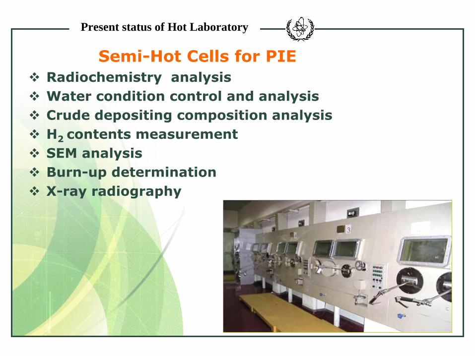
Semi-Hot Cells for PIE
Radiochemistry analysis
Water condition control and analysis
Crude depositing composition analysis
H2 contents measurement
SEM analysis
Burn-up determination
X-ray radiography

Present status of Hot Laboratory
Pool Side Inspection in HFETR
Underwater visual inspection
Disassembly for irradiated sub-assembly
Rod extraction
Kr-85 leakage detection
Dimension measurement
Eddy current test

Present status of Hot Laboratory
Renew of PIE Facilities
Anti-irradiation macro
camera system(Rees
R93/R981);
3 dimensional measurement
computer system;
Laser cutting system;
Deferential scanning calorimeter (NETSCH DSC404C )

Present status of Hot Laboratory
Blister test system for
dispersion fuel tubes ;
Burst test for high
temperature;
Auto grinding polisher;
Digital metallographic
microscope(LeikaMEF4A)
Renew of PIE Facilities

Present status of Hot Laboratory
Renew of Facilities for Irradiated Materials:
Instrumented
Charpy-V impact machine with auto specimen feeding system(ZwickRKP450)
Instrumented drop-
weight test machine
(Dynutup8250)
MTS810.10 universal
material test
machine

Present status of Hot Laboratory
SEM
Mass spectrometer;
Ion chromatography;
High performance liquid chromatography;
Some Experiences of Irradiation Test for Fuel
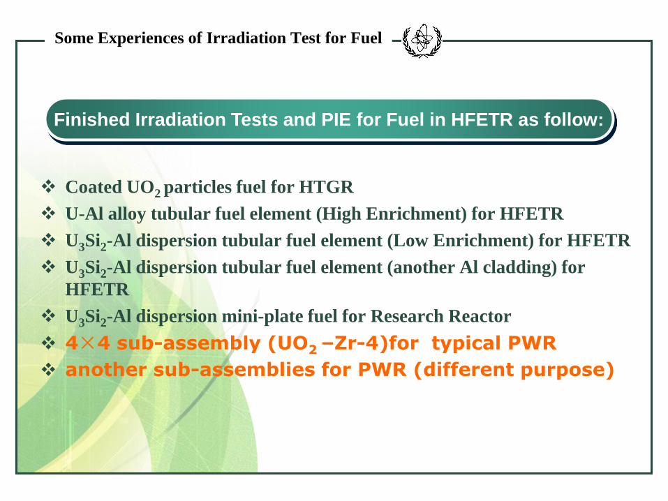
Coated UO2 particles fuel for HTGR
U-Al alloy tubular fuel element (High Enrichment) for HFETR
U3Si2-Al dispersion tubular fuel element (Low Enrichment) for HFETR
U3Si2-Al dispersion tubular fuel element (another Al cladding) for
HFETR
U3Si2-Al dispersion mini-plate fuel for Research Reactor
4×4 sub-assembly (UO2 –Zr-4)for typical PWR
another sub-assemblies for PWR (different purpose)
Finished Irradiation Tests and PIE for Fuel in HFETR as follow:

max. pressure:17.5MPa
Max. temperature :420℃
Total length: ~10m
Three tubes structure:
Out : isolation heat tube
Middle :pressure tube
Inner: flow distributing tube
Structure of Irradiation device
Fuel sub-assembly
Connecting loop
Thermal couples
Some Experiences of Irradiation Test for Fuel

Some Experiences of Irradiation Test for Fuel
4×4 test sub-assembly
Pre-irradiation
Post-irradiation (42000MWd/tU)

Some Experiences of Irradiation Test for Fuel
LEU tubular assembly for HFETR
Fuel Assembly Model
Post-irradiation (burn-up 55 % atom )
Some Experiences of Irradiation Test for Fuel
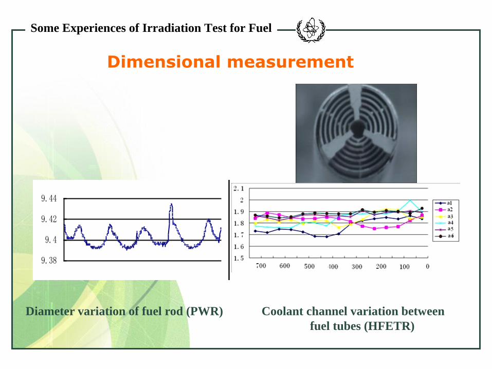
Dimensional measurement
Diameter variation of fuel rod (PWR)
9.38
9.4
9.42
9.44
Coolant channel variation between
fuel tubes (HFETR)

Some Experiences of Irradiation Test for Fuel
Gamma scanning
0
100
200
300
400
0 200 400 600 800 1000
mm
cps第一层
第二层
第三层
第四层
第五层
第六层
Relative distribution of Cs- 137 for fuel tubes (HFETR)

Some Experiences of Irradiation Test for Fuel
Blistering test (for LEU dispersion fuel tubes)
threshold temperature: 525℃
Burst test (for cladding tube of PWR )
-2 0 2 4 6 8 10 12 14
0
20
40
60
80
100
120
压力(MPa)
变形量(%)
Hoop strain(%) (350℃,0~160MPa )

Some Experiences of Irradiation Test for
Fuel
Macro examination
irradiated fuel meat(U3Si2) A PWR fuel rod

Some Experiences of Irradiation Test for Fuel
Microanalysis
Microstructures of irradiated fuel meat(U3Si2)

Some Experiences of Irradiation Test for Fuel
Microanalysis of cladding tube
fracture topography Hydrides distribution

Future Plan for PIE
Pool Side Inspection in NPP
Visual inspection of fuel assembly。
Dimensional measurement of fuel
assembly
Ultrasonic testing (UT)of FA for
failure rods detection
Oxide layer thickness measurement of
fuel rods
Disassembling & reconstitution of FA
Eddy current test of fuel rods
planning in 2011~2013

Future Plan for PIE
Renew of Devices and Instruments
ICP-AES mass spectrometer
New SEM
Reconstitution of Charpy-V specimens
2 cast iron cells to be reconstructed
Under construction in 2010~2012

NPIC Hot Laboratory plays a very important
role for PIE of fuel in China.
CONCLUSIONS
With reconstruction of some hot cells and
renew of instruments & facilities, more PIE works
would be performed in NPIC Hot Laboratory in
next decade.

Thank you for your attention !


