33
Activity 2: Load Analysis Minneapolis, MN International Falls, MN Activity 2: Load Analysis Page 1 of 33

Activity 2 Load Analysis
Minneapolis MN
International Falls MN
Activity 2 Load Analysis Page 1 of 33
Environmental Loads
Geographic Characteristics
Minnesota is located in the Northern Middle USA In Figure 21 the average yearly rainfall is displayed in comparison to other locations in the US Minnesota receives a US average amount of water each year Precipitation includes both rainfall as well as snow In Figure 22 the annual precipitation is displayed in terms of inches of water and a distinct distribution of geographic precipitation isolines exist The highest precipitation is observed near the Southeastern corner of the state at values of more than 32 inches of water The driest location is the Northwestern corner of the state where annual precipitation values of less than 20 inches of water are found
Minnesota
Figure 21 Geographic LocationYearly Rainfall (Blue- High Yellow-Low)
Activity 2 Load Analysis Page 2 of 33
Figure 22 Average Annual Precipitation (Minnesota)
In Figure 23 the average yearly temperatures contours are displayed for the state of Minnesota derived from 30 years of hourly data from 1961 through 1990 Large average temperature differences of up to 14deg F exist between the northern- and southernmost locations Average yearly temperatures of 44 to 46deg F are present at the southern regions of the Minnesota while 32 to 34deg F exist at the Northern and Northeastern regions
The US National Climatic Data Center (NCDC) provides 4 locations with 30-year weather data (SAMSON) that include solar radiation and rainfall precipitation data for the state of Minnesota These four meteorological locations are Minneapolis St Cloud International Falls and Rochester As described in Table 1 of the proposal due to the apparent time constraints two locations were selected Two of these have been selected to represent conditions that contain the widest characteristics of possible conditions present in (populated) Minnesota The two selected were
a) Minneapolis MN b) International Falls MN
Activity 2 Load Analysis Page 3 of 33
Figure 23 Average Yearly Temperature in Minnesota
Figures 4 and 5 displays 30 year plots of the monthly average minimum and extreme temperatures monthly rain precipitation monthly cooling degree days (based on 65deg F) and heating degree days for the two selected cities The results show the differences between these two cities in terms of the ambient conditions pointing out the much colder conditions at International Falls These locations will be used in the extensive hygrothermal modeling activity that is Activity 3 Advanced Moisture EngineeringModeling
The first activity required was to develop Moisture Design Years from the 30 year hourly data by selecting years that represent hygric loads appropriate for moisture design purposes In the past hygrothermal modeling used weather data from energy calculation models Weather years for energy calculations have serious limitations when employed in hygrothermal modeling as the criteria for their selection is completely different An analysis procedure developed at the International Energy Agency (IEA) Annex 24 on Heat Air and Moisture Transport in Highly Insulated Building Envelopes is used in this project to develop two weather years that coincide with the 10 percentile coldest and warmest years with corresponding hygric loads which are significantly different from those used in energy calculations The influence of rain loads is included in the analysis determining the hygric loads The reason for using the 10 percentile (rather than the worst conditions) is that a seasonal adjusted condensation load may be allowed to occur once every 10 years This load is expected be effectively dissipated by the envelope
Activity 2 Load Analysis Page 4 of 33
systems as some moisture capacity in terms of storage and release is present in most walls
a) b)
c) d)
Figure 24 Minneapolis Climatic Conditions
Activity 2 Load Analysis Page 5 of 33
a) b)
Figure 25 International Falls Climatic Conditions
Activity 2 Load Analysis Page 6 of 33
In Figure 26 the monthly average vapor pressure distribution is plotted for the city of Minneapolis Thirty years of hourly data were processed spanning through the period between 1961-1990 During the year the vapor pressure of the exterior is consistently lower than 900 Pa for approximately 6 months of the year This indicates a healthy drying potential towards the outside of the structure for vapor diffusion transport
0 4 8 12 Time (Months)
0
400
800
1200
1600
2000
2400
Vap
or
Pre
ssu
re (
Pa)
Jan June Dec
30 Years (1961-1990)
Figure 26 Vapor Pressure Distribution for Minneapolis
Activity 2 Load Analysis Page 7 of 33
In Figure 27 the monthly average vapor pressure distribution is plotted for the city of International falls The results show even drier conditions are present in terms of vapor moisture than for the city of Minneapolis A maximum of 8 months per year of possible drying conditions are available for International Falls
0 4 8 12 Time (Months)
0
400
800
1200
1600
2000
Vap
or
Pre
ssu
re (P
a)
Jan June Dec
30 Years (1961-1990)
Figure 27 Vapor Pressure Distribution for International Falls
Activity 2 Load Analysis Page 8 of 33
In Tables 1 and 2 yearly averaged hygrothermal loads are given for both locations
Table 1 Synopsis of Hygric Loads for Minneapolis
Year Temp PV RH Rain 1961 1 70877 921131 715778 661199 1962 2 61871 912707 724339 744498 1963 3 71550 949256 693322 505099 1964 4 77221 913351 687941 667099 1965 5 62446 856628 722614 1023997 1966 6 65737 864861 673847 625699 1967 7 62631 825349 682100 654399 1968 8 76428 924982 682347 972098 1969 9 72501 891647 690155 508698 1970 10 70601 927484 684938 785997 1971 11 70936 844420 653789 755998 1972 12 54736 856530 686249 589499 1973 13 85220 919322 676013 573299 1974 14 70904 837395 668468 493099 1975 15 74319 905406 680818 902498 1976 16 83433 777613 566604 425199 1977 17 73800 937291 676958 888698 1978 18 70807 917765 659986 783698 1979 19 65391 849579 648740 801898 1980 20 75691 823199 619145 561299 1981 21 83126 886026 656860 714398 1982 22 71293 873390 662100 743698 1983 23 79101 1013136 742937 1042490 1984 24 74294 870221 655193 941198 1985 25 67013 848034 659071 822298 1986 26 76622 961181 736554 941698 1987 27 100873 970919 670744 821099 1988 28 83551 869660 631444 481599 1989 29 67414 869720 666654 609699 1990 30 88172 936489 665858 851898
Activity 2 Load Analysis Page 9 of 33
1 2 3 4 5 6 7 8 9 10 11 12 13 14 15 16 17 18 19 20 21 22 23 24 25 26 27 28 29 30
Table 2 Synopsis of Hygric Loads for International Falls
Year Temp PV RH Rain 1961 37599 724496 702469 637998 1962 27933 741262 722317 738298 1963 35015 798230 708043 642298 1964 31251 766211 746551 688698 1965 20930 707738 740758 752797 1966 18551 741621 714991 666099 1967 20395 667887 678225 569198 1968 30470 746258 730062 748997 1969 27949 725321 731604 610298 1970 25831 731730 711393 586398 1971 27945 751017 729175 639498 1972 22206 672585 648801 483599 1973 46916 744139 658969 747198 1974 27070 627617 618729 626498 1975 29880 737973 688606 664499 1976 26871 700352 687152 563699 1977 31164 769288 720554 823697 1978 18889 690735 652392 640398 1979 10676 678682 714441 578399 1980 34433 699539 668147 511698 1981 49899 794688 721360 567498 1982 22655 780058 755243 642398 1983 40016 825154 750632 648797 1984 32960 745223 709339 542698 1985 17007 691675 732261 788597 1986 38001 750841 734946 469998 1987 59888 788955 708743 505699 1988 37327 759751 707918 635798 1989 23553 733293 712032 590199 1990 42575 741166 698790 526299
Activity 2 Load Analysis Page 10 of 33
Wind-driven rain is a critical hygrothermal load Indeed in most instances this load is several times greater than all other load combined As such the selection of orientation for the hygrothermal simulations must be assigned based on analysis of the amount of water load each orientation receives The maximum load must be established for each orientation before a moisture engineering analysis is preformed This requires a better understanding of the prominent wind direction and concurrent wind driven rain occurrences In this project this analysis was performed for both weather files (10 percentile cold and hot year) used in the hygrothermal simulations
In Figures 8 and 9 the rain and wind roses are plotted out using the selected moisture design years for Minneapolis In Minneapolis 378 of the time calm winds exist (lower than 05 ms or 1 mph) while the average wind speed is 483 ms (11 mph) Prominent wind directions are northwest and southeast but south and southwest directions also show wind movement From the rain rose plots wind-driven rain activity exists in three main quadrants spanning from northwest to southeast
In Figures 10 and 11 wind and rain roses are plotted out for International Falls For this location calm winds exist 823 of the time more than twice as long as in Minnesota The average wind speed is 432 ms (10 mph) slightly lower than for Minneapolis The average precipitation for Minneapolis is 019 mmhr (00075 inhr) while for International Falls a value of 032 mmhr (00126 inhr) exists
All results presented in the rain roses include the effect of precipitation in both liquid and ice phase (snow)
Activity 2 Load Analysis Page 11 of 33
WIND ROSE PLOT
Station 14922 - MINNEAPOLIS-ST PAULINTL ARP MN
WEST
NORTH
SOUTH
EAST
3
6
9
12
15
COMMENTS
PLOT YEAR-DATE-TIME
1965 1990 Jan 1 - Dec 31 Midnight - 11 PM
ORIENTATION
Direction (blowing from)
W ind Sp ee d (ms)
gt1 1 06
84 9 -1 1 06
54 0 -8 4 9
33 4 -5 4 0
18 0 -3 3 4
05 1 -1 8 0
DISPLAY
Wind Speed
UNIT
ms
CALM WINDS
378
AVG WIND SPEED
483 ms
Nov 29-2001
11292001
Achilles Karagiozis
Achilles Karagiozis
ORNL
Oak Ridge National Laboratory
PROJECTPLOT NO
WRPLOT View 35 by Lakes Environmental Software - wwwlakes-environmentalcom
Figure 28 Wind Speed Rose for Minneapolis
RAIN ROSE PLOT
Station 14922 - MINNEAPOLIS-ST PAULINTL ARP MN
COMMENTS
WEST
NORTH
SOUTH
EAST
02
04
06
08
1
PLOT YEAR-DATE-TIME
1965 1990 Jan 1 - Dec 31 Midnight - 11 PM
ORIENTATION
Direction (blowing from)
Pr ec ip In t ( mm hr )
gt2 1
17 - 21
11 - 16
7 -1 0
4 - 6
1 - 3SITY
DISPLAY
Precipitation Intensity
UNIT
mmhr
DRY HOURS
9387
AVG PRECIPITATION INTEN
019 ms
Nov 29-2001
11292001
Achilles Karagiozis
Achilles Karagiozis
ORNL
Oak Ridge National Laboratory
PROJECTPLOT NO
WRPLOT View 35 by Lakes Environmental Software - wwwlakes-environmentalcom
Figure 29 Rain Rose for Minneapolis
Activity 2 Load Analysis Page 12 of 33
WIND ROSE PLOT
Station 14918 - INTERNATIONAL FALLSINTL ARP MN
WEST
NORTH
SOUTH
EAST
2
4
6
8
10
COMMENTS
PLOT YEAR-DATE-TIME
1973 1985 Jan 1 - Dec 31 Midnight - 11 PM
ORIENTATION
Direction (blowing from)
Wind Speed (m s)
gt 1106
849 - 1106
540 - 8 49
334 - 5 40
180 - 3 34
051 - 1 80
DISPLAY
Wind Speed
UNIT
ms
CALM WINDS
823
AVG WIND SPEED
432 ms
Nov 29-2001
11292001
Achilles Karagiozis
Achilles Karagiozis
ORNL
Oak Ridge National Laboratory
PROJECTPLOT NO
WRPLOT View 35 by Lakes Environmental Software - wwwlakes-environmentalcom
Figure 210 Wind Speed Rose for International Falls
RAIN ROSE PLOT
Station 14918 - INTERNATIONAL FALLSINTL ARP MN
COMMENTS
WEST
NORTH
SOUTH
EAST
02
04
06
08
1
PLOT YEAR-DATE-TIME
1973 1985 Jan 1 - Dec 31 Midnight - 11 PM
ORIENTATION
Direction (blowing from)
Precip In t (mmhr)
gt 21
17- 21
11- 16
7 - 10
4 - 6
1 - 3SITY
DISPLAY
Precipitation Intensity
UNIT
mmhr
DRY HOURS
9387
AVG PRECIPITATION INTEN
032 mmhr
Nov 29-2001
11292001
Achilles Karagiozis
Achilles Karagiozis
ORNL
Oak Ridge National Laboratory
PROJECTPLOT NO
WRPLOT View 35 by Lakes Environmental Software - wwwlakes-environmentalcom
Figure 211 Rain Rose for International Falls
Activity 2 Load Analysis Page 13 of 33
In Figures 212a through 213b the wind-driven rain on four orientations is plotted out In Figures 212a and 213a the maximum rainfall possible over a 180deg angle is plotted out In 212b and 213b the actual amount impinging is displayed
500
Am
ou
nto
f A
vaila
ble
Pre
cip
itat
ion
(m
m)
400
300
200
100
0
0 90 180 270 360 Orientation
(0-North 90-East 180-South 270-West)
Figure 212a Possible Rain (before effect of Wind) for Minneapolis
0 90 180 270 360 Orientation
(0-North 90-East 180-South 270-West)
0
4
8
12
Am
ou
nt
of
Av
aila
ble
Pre
cip
itatio
n (
mm
)
Figure 212b WDR (Wind-driven rain) for Minneapolis
Activity 2 Load Analysis Page 14 of 33
0 90 180 270 360 Orientation
(0-North 90-East 180-South 270-West)
0
100
200
300
400
500
Am
oun
t of A
vaila
ble
Pre
cipi
tatio
n (m
m)
International Fall (Cold Year)
Figure 213a Possible Rain (before effect of Wind) for International Falls
0 90 180 270 360 Orientation
(0-North 90-East 180-South 270-West)
0
4
8
12
16
Am
oun
t of
Ava
ilab
le P
reci
pita
tion
(mm
)
International Fall (Cold Year)
Figure 213b WDR (Wind-driven rain) for International Falls
To establish these values the following SPC 160P methodology was used
Activity 2 Load Analysis Page 15 of 33
Proposed ASHRAE SPC 160P Driving Rain Load
Intent A method to provide an approximation of the magnitude of rainwater deposited on the exterior surface of vertical walls
Basis Built upon BS 81041992 (EuroNorm pending) and recent research in Europe and North America Bibliography to follow
Approach 1 Calculate driving rain free-wind (macro-climate) 2 Modify for exposure effects (meso-climate) 3 Calculate deposition to account for building shape and overhangs (micro-climate)
This approach is intended to be used for hourly meteorological data
1 Free wind driving rain Lacy developed a simple approximation of free-wind driving rain (r v) for a given direction
r v = 0222 middot Vmiddot r h 088
This is valid at points away from buildings or complex topography More recent and detailed measurements (Straube 1997) have improved the accuracy of this type of relation by using a more complex equation
For most purposes under normal exposure conditions a simple equation of the form r v = 020 middot V middot r h
is recommended
2 Exposure Factor
Topography and surrounding buildings can either increase or decrease the driving rain by modifying the wind speed To account for this effect it is recommended that an Exposure Factor be applied (Table A1)
Exposure Class Exposure Factor Normal 10 Exposed (eg coastal hill top site funneled wind) 13 Sheltered (eg trees neighboring bldgs depression) 07 Table A1 Exposure Factor
To account for exposure the equation from part one
r v = EF middot 020 middot V middot r h
where EF is the Exposure Factor
Activity 2 Load Analysis Page 16 of 33
Taller buildings are exposed to higher wind speeds and hence higher driving rain loads To account for this effect a Height Factor should be applied The Height Factor can be calculated from
HF(z) = (z10)a
where HF(z) is the Height Factor at a height z (m) above grade and a is the gradient exponent typically 010 for open coastal areas 020-025 for suburban and as much as 04 for built-up urban areas Reference can be made to any wind load code for more detail
In lieu of more detailed info an exponent of 025 is recommended For low-rise buildings (under 10 m in height eg 2 to 3 stories) the HF=10
Height Above Grade (m) Height Factor lt10 10 20 12 50 15
gt50 Detailed Calculations Recommended Table A2 Height Factor for Suburban Conditions
3 Rain Deposition Factor The orientation of the wall and the shape of the building being considered have a significant effect on how driving rain in the free wind is deposited on the enclosure elements (windows walls etc) To account for orientation the cosine of the angle between the wind direction and a line perpendicular to the wall should be applied as an orientation factor A Deposition Factor is used to account for the building shape For a rectangular building with a flat roof the DF is between 03 and 05 depending on the location on the wall In upper corners the DF can approach 10 Note that these Deposition Factors do not account for the response of the wall eg drainage from non-absorptive or saturated surfaces above For the gable ends of buildings with pitched roofs the DF is essentially the same as for a flat roofed building but without the higher values near the upper corners For the eaves side of a building with a pitched roof the DF is 05 if the overhang is less than 02 m For overhangs of more than 02 m the DF is reduced to 035 (Gutters should be provided to avoid concentration of rainfall off the roof)
q
Wind Direction
Activity 2 Load Analysis Page 17 of 33
10
10 10
10
Plan View of Building
10 05 10
04
Flat Roof
035 035
05
Pitched Roof Deposition Factors for Windward Walls
Hence the final equation becomes
rbv = EF middot DFmiddot HF middot 020 middot V middot cos q middot r h
where EF is the Exposure Factor DF is the Deposition Factor HF is the Height Factor V is the hourly average wind velocity at 10 m q is the angle between the wind direction and the perpendicular to the wall r h is the horizontal rainfall intensity (mmhr) rbv is the amount of rain deposition on a vertical wall (kgm2hr)
Activity 2 Load Analysis Page 18 of 33
Appendix A
For tall buildings the velocity of the free-wind at the height of interest on the building should be accounted for The wind velocity changes with height according to
V(z) = V10 (z10)a
WhereV(z) is the wind velocity (ms) at a height z (m) above grade V10 is the velocity at the standard height of 10 m above grade and a is the gradient exponent typically 010 for open coastal areas 020-025 for suburban and as much as 04 for built-up urban areas Reference can be made to any wind load code for more detail In lieu of more detailed info an exponent of 02 is recommended
The adjusted wind velocity V(z) can be used in lieu of the height and exposure factors (HF amp EF) Otherwise the height correction factor can also be read from Table A1
Activity 2 Load Analysis Page 19 of 33
Indoor Conditions
The interior environmental conditions in residential buildings are dynamic Interior conditions change as a function of the operation of the building (mechanical ventilation systems humidifiers dehumidifiers etc) changes of the exterior climatic conditions inhabitant activities plants and the kind of objects placed in the interior environment (moisture storage) Indoor conditions that affect the heat air and moisture transport in building envelopes are
bull Temperature conditions bull Moisture content of the air (RH must be used carefully) bull Internal pressures bull Thermal sources bull Moisture sources
In nearly all cases operation of buildings is better controlled thermally than in any other way A thermostat is installed in every home allowing better control of the air space
A significant amount of moisture can be produced internally and intentional means of removing that moisture do not exist most of the time Usually water vapor is removed by air change either by natural air leakage through the building envelope or by mechanical vent ilation systems Another mechanism to remove excess water vapor is to employ some kind of dehumidification equipment with designed capacity for interior moisture production loads The obvious approach to maintain good indoor air quality is to control the level of moisture in the interior air The most cost-effective way to achieve this is to control moisture at the source
Sources of Moisture
There are many sources of moisture that can increase the amount of water in the building interior Some of these sources have nothing to do with the general operation of the building such as the construction moisture content of the building materials water table levelwater and vapor ingress from the ground and basement and crawlspace walls storing and transporting large quantities of water to the interior Wind driven rain and water penetration of the building envelope exterior and interior elements may allow seasonal storage effects Most of the time each source is independent of the other but combined together they may account for significant amount of available water In Denmark worked carried out by Kohl (1986) grouped the different sources of moisture production in dwellings as
Activity 2 Load Analysis Page 20 of 33
bull Transpiration from human body bull Evaporation from plants bull Personal hygiene such as bathing bull Cleaning of dwellings bull Washing up bull Laundering and subsequent drying bull Cooking
People as Moisture Sources
Inhabitants and their use of the building may provide a significant amount of water They may not necessarily be the largest source all the time Table 3 from a recent publication by LBNL shows the distribution of moisture loads for various activities in terms of pints of water per day Figure 214 plots out the amount of water that a specific activity may produce in liters
Table 3 Moisture Sources
Activity 2 Load Analysis Page 21 of 33
Figure 214 Water production (BSI Richard L Quirouette)
In general open literature data for a family of four give values of 35 kgday (77 lbsday) of moisture release from our body plants contribute 046 kgday (10 lbday) personal hygiene about 05 kgday (11 lbday) (family of four about 13 kgday or 29 lbsday) contributions due to house cleaning about 02 kgday (04 lbday) washing up approximately 04 kgday (09 lbday) laundry and drying anywhere from 01 kgday to 18 kgday (02-40 lbsday) cooking approximately 0897 kgday (2 lbsday) If these are all summed up a typical family of 4 may produce 4 to 14 kgday (9-31 lbsday) of moisture This numbers can be compared to numbers given by NRCan for a typical household four people of up to 160 liters (42 gallons) of water into the air each month Add to that other common sources of moisturemdashfrom long showers to leaky plumbingmdashand itrsquos easy to see how homes can suffer from poor air quality and major structural problems due to excessive moisture In addition health experts know that fungi mold and dust mites flourish in damp areas and can cause health problems such as allergies and asthma Having the right moisture level in onersquos house means greater energy fitness savings in home repairs and better health for years to come
Gas appliances can release up to 13 kgday (3 lbsday) saunas and hot tubs can also release significant amounts of water to the inside of the house as can drying of firewood indoors
Activity 2 Load Analysis Page 22 of 33
How is the interior environment affected in Minnesota
Indoor Conditions
The interior environmental conditions in residential buildings are dynamic Interior conditions change as a function of the operation of the building (mechanical ventilation systems humidifiers dehumidifiers etc) changes of the exterior climatic conditions inhabitant activities plants and the kind of objects placed in the interior environment (moisture storage) A significant amount of moisture can be produced internally and a means of removing that moisture should exist Usually water vapor is removed by air change either by natural air leakage through the building envelope or by mechanical ventilation systems Another mechanism to remove excess water vapor is to employ some kind of dehumidification equipment with designed capacity for interior moisture production loads The obvious approach to maintain good indoor air quality is to control the level of moisture in the interior air The most cost-effective way to achieve this is to control moisture at the source
ASHRAE recommends that indoor temperatures during the winter months be maintained between 68 and 75deg F and indoor temperatures during the summer months should be between 73 and 79deg F In practice complaints may occur with any temperature not maintained at 72deg F with some air circulation Relative humidity (RH) measures the amount of moisture in the air ASHRAE recommends RH be maintained between 30 and 60 for indoor environments RH below 30 can cause drying of the mucous membranes and discomfort for many people RH above 60 for extended time periods promotes indoor microbial growth
HVAC systems are designed to supply fresh air into the occupied space supplying fresh air into the building and diluting contaminants and therefore preventing buildup ASHRAE specifies the minimum amount of outside air supplied to an occupied building as 20 cubic feet per minute (CFM) per person in each occupied zone If the HVAC system is shut down overnight the system should be started at least one hour before occupancy to provide adequate ventilation Other contributors to stale and poorly mixed air include poor location of supply and exhaust air diffusers improper building or system design (often caused by change of building occupancy from original design configuration with inadequate attention during remodeling) or indoor structures that prevent free movement of air
Carbon monoxide (CO) is a common result of the presence of or proximity to sources of combustion It is present to some degree whenever fuel-operated systems are used High levels are an immediate threat to life Lower levels are a cause for health concern Concentrations should be ma intained as close to undetectable as possible
Activity 2 Load Analysis Page 23 of 33
Interior Environment Approach (This Project)
INTRODUCTION
A recent paper (TenWolde and Walker 2001) describes a state-of-the-art methodology to obtain the interior environmental conditions in terms of an analysis approach and design values Hygrothermal models require the inputs of interior environmental conditions and are extremely sensitive to the assumed moisture boundary conditions For instance during winter the moisture conditions in walls depend greatly on the indoor humidity conditions (TenWolde et al 1995) Thus a consistent approach to moisture design demands a consistent framework for design assumptions or assumed ldquoloadsrdquo The question whether or not design features such as vapor retarders or ventilation systems are necessary cannot be answered unless there is a consensus definition of the interior and exterior moisture boundary conditions that the building is expected to be able to sustain without negative consequences to itself or its inhabitants No standardized methodology for moisture design exists as yet but ASHRAE Standard Committee 160P Design Criteria for Moisture Control in Buildings is attempting to formulate appropriate design assumptions for moisture design analysis and criteria for acceptable performance The ASHRAE 160P committee is trying to arrive at design loads despite a general lack of data and information The committee is formulating several research projects to obtain better data and they will recommend these projects for funding by ASHRAE
According to TenWolde and Walker (2001) the SPC 160P standard will include interior design loads (temperature humidity and air pressure) as well as exterior design loads (temperature humidity and rain) Although it is common to impose very stringent criteria for structural design because of safety concerns moisture damage usually occurs over a long period of time and usually has less disastrous although sometimes costly consequences A consensus is beginning to emerge that a 10 likelihood of failure is an appropriate level in building moisture design analysis and we will use this for the purposes of this paper The definition of failure will also be addressed in ASHRAE Standard 160P
In a moisture analysis for building envelope design the choice of indoor environmental conditions is extremely important especially for buildings in cold climates Several European countries have defined Indoor Climate Classes For instance Tammes and Vos (1980) describe four climate cla sses for use in the Netherlands based on interior vapor pressure ranges This approach requires a different definition for each climate and does not account for large seasonal changes Sanders (1996) and the IEA Annex 24 take a different approach and define four climate classes on the basis of three critical indoor vapor pressures or ldquopivot pointsrdquo These pivot points are related to the occurrence of condensation in a north-facing wall net annual moisture accumulation in a north-facing wall or net annual moisture accumulation in a flat roof These pivot points depend on construction and climate
According to TenWolde and Walker (2001) the approached favored within SPC 160P is to be independent of construction type but will include the influences of ventilation and
Activity 2 Load Analysis Page 24 of 33
air-conditioning equipment as well as controls that may or may not be part of the building design In residential buildings in Minnesota indoor humidity is rarely explicitly controlled During winter conditions the indoor humidity depends on a combination of sources (such as people and foundation moisture) and building ventilation In some extreme climates (such as Minnesota) houses are humidified during the winter In that case an estimate must be made for this additional moisture generation rate For summer conditions there is the added complication of air conditioner and dehumidifier operation for the whole house or individual rooms Unfortunately the moisture removal performance of these devices is highly variable and depends on a host of factors that cannot easily be dealt with during the design process
DESIGN INDOOR HUMIDITY FOR HEATING
Humidity of indoor air is the result of a balance between moisture gains moisture removal from the building and net moisture exchange with hygroscopic materials inside the building TenWolde (1994a 1994b) showed that moisture storage in residences stabilizes the indoor humidity and that daily or even weekly averages can be used for the purpose of building moisture analysis Ignoring storage and using time-averaged values for the other parameters allows the determination of the indoor vapor pressure
P matm sPi = Po + (1)062198mv
where Pi = indoor vapor pressure in Hg (Pa) Po = outdoor vapor pressure in Hg (Pa) P atm = atmospheric pressure in Hg (Pa) ms = moisture source rate lbh (kgs) mv = ventilation rate lbh (kgs)
The ventilation rate for residential buildings is often expressed in terms of air changes per hour rather than as a mass flow rate The mass flow rate can be obtained from the air change rate using Equation 2
rVI mv = (2)
n
where r = air density lbft3 (kgm3) V = building volume ft3 (m3) I = air exchange rate 1h n = 1 in IP units 3600 sh in SI units
Activity 2 Load Analysis Page 25 of 33
Combining Equations 1 and 2 with the assumption of a standard atmospheric pressure of 299 in Hg (1013 kPa) and air density of 0075 lbft3 (12 kgm3) yields a simple equation
cmspi = po + (3)VI
where c = 641 in Hg ft3lb (489 times 105 m2s2)
The moisture source term in Equation 1 includes both generation (eg people) and dehumidification If dehumidification exceeds the rate at which moisture is added this term becomes negative In this project we adopted the equations above but also accounted for the transient moisture capacity of the air The air was allowed to be influenced by the previous hour condition In addition humidification was allowed to bring the relative humidity to either 15 or until surface condensation appeared on a window with a U value of 035 (IP) While it is well understood that windows have a multi-dimensional distinct distribution of heat flow this uniform U value approach of 035 allowed additional sophistication than that proposed in the ASHRAE 160P Standard and is expected to give values that are a closer representation to reality It is a fact that people limitcontrol their humidification system whenever vapor condenses on windows
Table 4 shows measured and established data from Christian (1993) and TenWolde (1988 1994) In this project three floor areas were used 1400 ft3 2000 ft3
and 2457 ft3 The two exterior climates (International Falls and Minneapolis) were entered into existing software developed at ORNL that determines the interior environmental conditions
Table 4 Daily Moisture Production (TenWolde and Walker 2001)
Activity 2 Load Analysis Page 26 of 33
Figures 215 through 220 show the influence of ventilation on the interior conditions for the city of Minneapolis MN for three seasons Winter spring and summer conditions were investigated for the corresponding months of January April and July
Figures 215 217 and 219 show average monthly local temperatures and relative humidity for a period of 30 years Figures 216 218 and 220 show the interior relative humidity as a function of RH and 3 levels of moisture production rates of 5kgday 10kgday and 20kgday (13 26 and 53 galday) The setpoint temperature and relative humidities were chosen from the 30 year average conditions shown in Figures 215 217 and 219
For a residence of 2457 ft2 it is evident that in January with the exception of a very low moisture production rate of 5 kgday the interior relative humidity can be high enough to lead to mold growth on wall surfaces and condensation on windows At a ventilation rate of 025 ACH center of room relative humidities easily exceed 40 This will result in condensation on typical glazing and result in mold growth at exterior walls where the gypsum board surface RH will exceed 80 However at a ventilation rate of 035 ACH interior relative humidities will remain in the 20 to 30 range avoiding window condensation and mold However with typical building envelope tightness average air change rates of 035 ACH cannot be achieved Similar behavior is demonstrated for April where even higher interior relative humidities were found
From these results one can observe that under normal building operating conditions with a family of 4 the interior relative humidity becomes prohibitively large without an appropriate mechanical ventilation system that maintains ACH rates at 035 (for a large part of the year)
Activity 2 Load Analysis Page 27 of 33
80 0
January Month RH January Monthly T
Minneapolis MN
1960 1970 1980 1990
76 -4
72 -8
68 -12
64 -16
Rea
ltive
Hu
mid
ity (
)
Tem
pera
ture
( oC
)
60 -20
Figure 215 Monthly Average Exterior T and RH for January (Minneapolis)
Minneapolis Residence 2457 sf
0
20
40
60
80
100
0 05 1 15 2 25 3
Air Changes Per Hour
Inte
rior
RH
low (5 kgday) average (10 kgday) high (20kgday)
Moisture Production Rate
Minneapolis Jan Outside Air -10 C70RH
Figure 216 Effect of Ventilation and Moisture Production on Interior RH (January)
Activity 2 Load Analysis Page 28 of 33
80 12
1960 1970 1980 1990
April Month RH April Monthly T
Minneapolis MN
Rea
ltive
Hu
mid
ity (
)
10
70
8
6
60
4
Tem
pera
ture
( oC
)
50 2
Figure 217 Monthly Average Exterior T and RH for April (Minneapolis)
Minneapolis Residence 2457 sf
0
20
40
60
80
100
0 05 1 15 2 25 3
Air Changes Per Hour
Inte
rior
RH low (5 kgday)
average (10 kgday) high (20kgday)
Moisture Production Rate
Minneapolis Apr Outside Air 8 C60RH
Figure 218 Effect of Ventilation and Moisture Production on Interior RH (April)
Activity 2 Load Analysis Page 29 of 33
80 26 July Month RH July Monthly T
1960 1970 1980 1990
Rea
ltive
Hum
idity
()
24
70
22
60
20
50 18
Tem
per
atur
e ( o
C)
Figure 219 Monthly Average Exterior T and RH for July (Minneapolis)
Minneapolis Residence 2457 sf
0
20
40
60
80
100
0 05 1 15 2 25 3
Air Changes Per Hour
Inte
rior
RH
low (5 kgday) average (10 kgday) high (20kgday)
Moisture Production Rate
Minneapolis Jul Outside Air 23 C65RH
Figure 220 Effect of Ventilation and Moisture Production on Interior RH (July)
Activity 2 Load Analysis Page 30 of 33
In Figures 221 through 224 the corresponding instantaneous values of the interior RH versus time in hours (0 is January) is plotted out for a period of two years (10 cold and 10 hot year) The moving average is shown as a weekly averaged number every 168 hours (7 days) Results clearly show the effects of moisture source rates and air exchange rate Permeable wall systems (Category 2) here are shown to not be able to appropriately dilute the moisture production rates of a family of 4
100
090
080
070
Series1060
RH
(-)
050 168 per Mov Avg
040 (Series1)
030
020
010
000 1 2865 5729 8593 11457 14321 17185
Time (hr)
Figure 221 Interior RH (Minneapolis) w 5 kgday moisture source (3 ACH)
100
090
080
070
060 Series1
RH
(-)
040
050 168 per Mov Avg (Series1)
030
020
010
000 1 2865 5729 8593 11457 14321 17185
Time (hr)
Figure 222 Interior RH (Minneapolis) w 5 kgday moisture source (035 ACH 1 gm3)
Activity 2 Load Analysis Page 31 of 33
RH
(-)
100
090
080
070
060 Series1
040
050 168 per Mov Avg (Series1)
030
020
010
000 1 2865 5729 8593 11457 14321 17185
Time (hr)
Figure 223 Interior RH (Minneapolis) w 20 kgday moisture source (3 ACH)
100
090
080
070
Series1060
RH
(-)
030
040
050 168 per Mov Avg (Series1)
020
010
000 1 2865 5729 8593 11457 14321 17185
Time (hr)
Figure 224 Interior RH (Minneapolis) w 20 kgday moisture source (03 ACH 417 gm)
Activity 2 Load Analysis Page 32 of 33
List of Figures
Figure 21 Geographic LocationYearly Rainfall (Blue- High Yellow-Low) 2 Figure 22 Average Annual Precipitation (Minnesota) 3 Figure 23 Average Yearly Temp erature in Minnesota 4 Figure 24 Minneapolis Climatic Conditions 5 Figure 25 International Falls Climatic Conditions 6 Figure 26 Vapor Pressure Distribution for Minneapolis 7 Figure 27 Vapor Pressure Distribution for International Falls 8 Figure 28 Wind Speed Rose for Minneapolis 12 Figure 29 Rain Rose for Minneapolis 12 Figure 210 Wind Speed Rose for International Falls 13 Figure 211 Rain Rose for International Falls 13 Figure 212a Possible Rain (before effect of Wind) for Minneapolis 14 Figure 213a Possible Rain (before effect of Wind) for International Falls 15 Figure 214 Water production (BSI Richard L Quirouette) 22 Figure 215 Monthly Average Exterior T and RH for January (Minneapolis) 28 Figure 216 Effect of Ventilation and Moisture Production on Interior RH (January) 28 Figure 217 Monthly Average Exterior T and RH for April (Minneapolis) 29 Figure 218 Effect of Ventilation and Moisture Production on Interior RH (April) 29 Figure 219 Monthly Average Exterior T and RH for July (Minneapolis) 30 Figure 220 Effect of Ventilation and Moisture Production on Interior RH (July) 30 Figure 221 Interio r RH (Minneapolis) w 5 kgday moisture source (3 ACH) 31 Figure 222 Interior RH (Minneapolis) w 5 kgday moisture source (035 ACH 1 gm3) 31 Figure 223 Interior RH (Minneapolis) w 20 kgday moisture source (3 ACH) 32 Figure 224 Interior RH (Minneapolis) w 20 kgday moisture source (03 ACH 417 gm) 32
List of Tables
Table 1 Synopsis of Hygric Loads for Minneapolis 9 Table 2 Synopsis of Hygric Loads for International Falls 10 Table 3 Moisture Sources 21 Table 4 Daily Moisture Production (TenWolde and Walker 2001) 26
Activity 2 Load Analysis Page 33 of 33
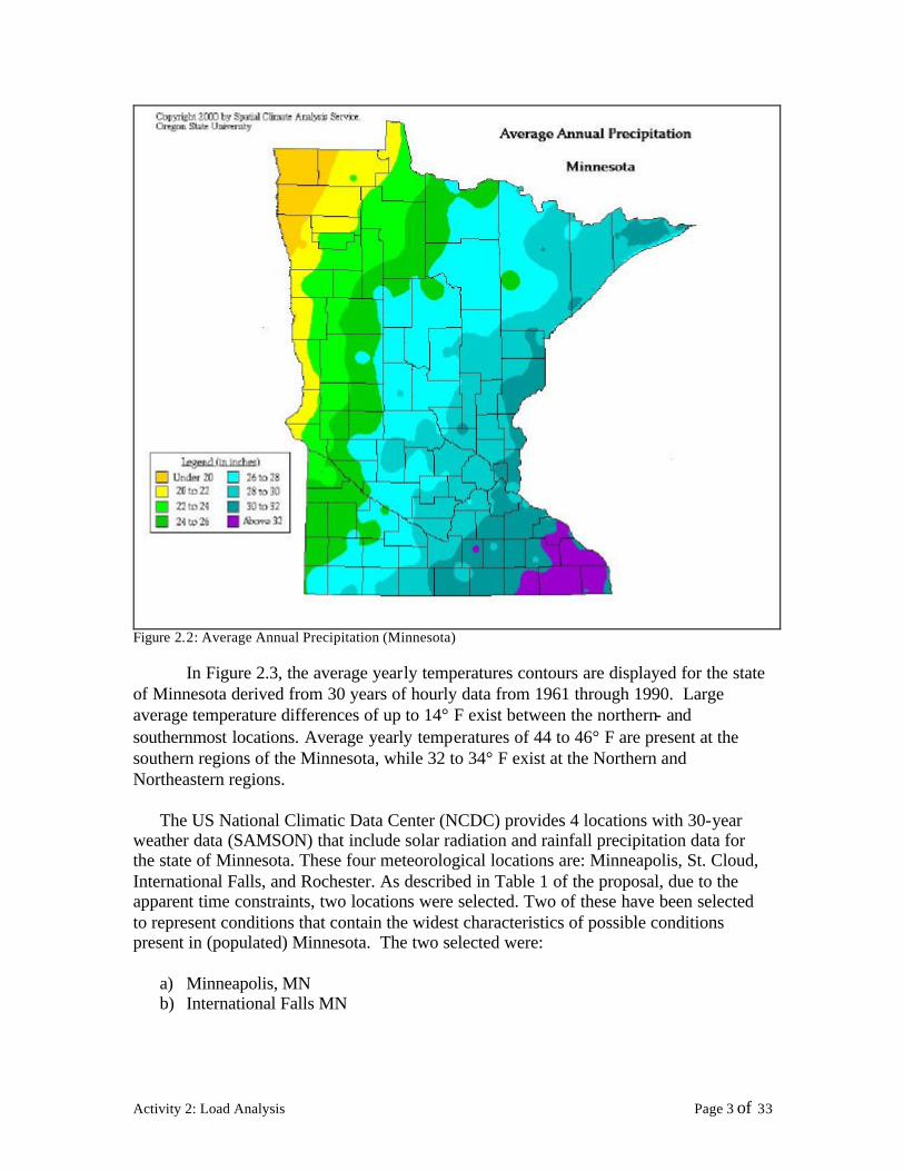
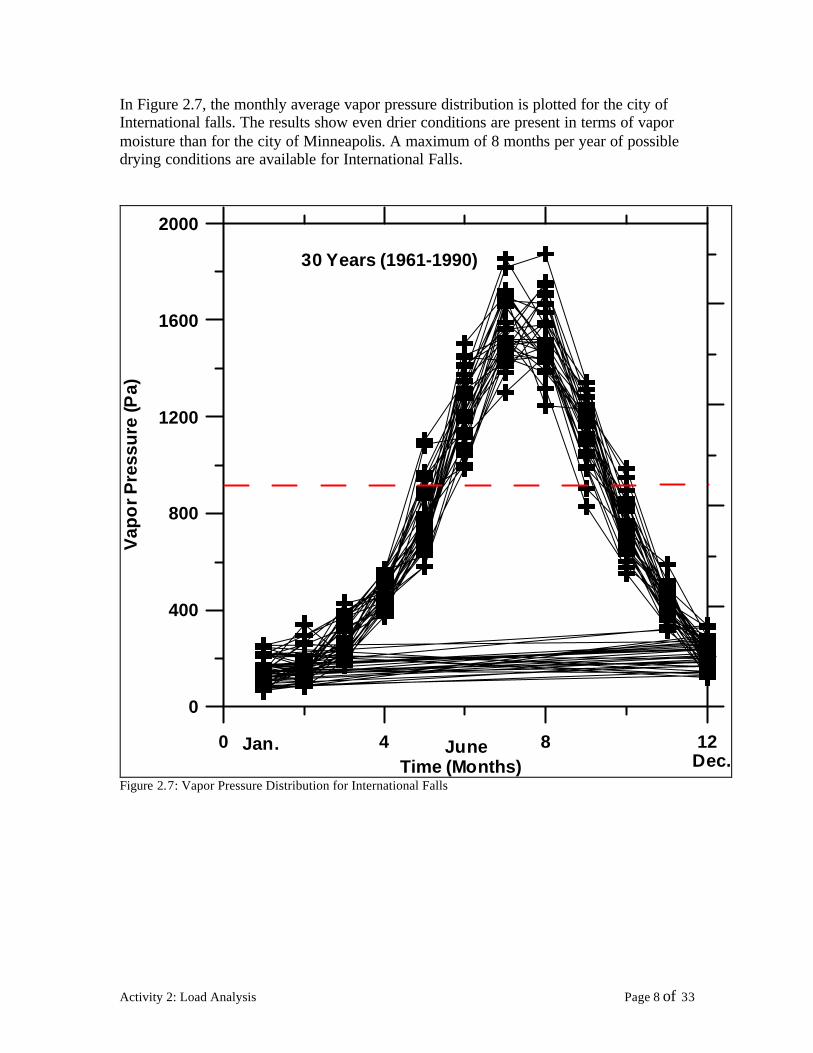

WIND ROSE PLOT
Station 14922 - MINNEAPOLIS-ST PAULINTL ARP MN
WEST
NORTH
SOUTH
EAST
3
6
9
12
15
COMMENTS
PLOT YEAR-DATE-TIME
1965 1990 Jan 1 - Dec 31 Midnight - 11 PM
ORIENTATION
Direction (blowing from)
W ind Sp ee d (ms)
gt1 1 06
84 9 -1 1 06
54 0 -8 4 9
33 4 -5 4 0
18 0 -3 3 4
05 1 -1 8 0
DISPLAY
Wind Speed
UNIT
ms
CALM WINDS
378
AVG WIND SPEED
483 ms
Nov 29-2001
11292001
Achilles Karagiozis
Achilles Karagiozis
ORNL
Oak Ridge National Laboratory
PROJECTPLOT NO
WRPLOT View 35 by Lakes Environmental Software - wwwlakes-environmentalcom
Figure 28 Wind Speed Rose for Minneapolis
RAIN ROSE PLOT
Station 14922 - MINNEAPOLIS-ST PAULINTL ARP MN
COMMENTS
WEST
NORTH
SOUTH
EAST
02
04
06
08
1
PLOT YEAR-DATE-TIME
1965 1990 Jan 1 - Dec 31 Midnight - 11 PM
ORIENTATION
Direction (blowing from)
Pr ec ip In t ( mm hr )
gt2 1
17 - 21
11 - 16
7 -1 0
4 - 6
1 - 3SITY
DISPLAY
Precipitation Intensity
UNIT
mmhr
DRY HOURS
9387
AVG PRECIPITATION INTEN
019 ms
Nov 29-2001
11292001
Achilles Karagiozis
Achilles Karagiozis
ORNL
Oak Ridge National Laboratory
PROJECTPLOT NO
WRPLOT View 35 by Lakes Environmental Software - wwwlakes-environmentalcom
Figure 29 Rain Rose for Minneapolis
Activity 2 Load Analysis Page 12 of 33
WIND ROSE PLOT
Station 14918 - INTERNATIONAL FALLSINTL ARP MN
WEST
NORTH
SOUTH
EAST
2
4
6
8
10
COMMENTS
PLOT YEAR-DATE-TIME
1973 1985 Jan 1 - Dec 31 Midnight - 11 PM
ORIENTATION
Direction (blowing from)
Wind Speed (m s)
gt 1106
849 - 1106
540 - 8 49
334 - 5 40
180 - 3 34
051 - 1 80
DISPLAY
Wind Speed
UNIT
ms
CALM WINDS
823
AVG WIND SPEED
432 ms
Nov 29-2001
11292001
Achilles Karagiozis
Achilles Karagiozis
ORNL
Oak Ridge National Laboratory
PROJECTPLOT NO
WRPLOT View 35 by Lakes Environmental Software - wwwlakes-environmentalcom
Figure 210 Wind Speed Rose for International Falls
RAIN ROSE PLOT
Station 14918 - INTERNATIONAL FALLSINTL ARP MN
COMMENTS
WEST
NORTH
SOUTH
EAST
02
04
06
08
1
PLOT YEAR-DATE-TIME
1973 1985 Jan 1 - Dec 31 Midnight - 11 PM
ORIENTATION
Direction (blowing from)
Precip In t (mmhr)
gt 21
17- 21
11- 16
7 - 10
4 - 6
1 - 3SITY
DISPLAY
Precipitation Intensity
UNIT
mmhr
DRY HOURS
9387
AVG PRECIPITATION INTEN
032 mmhr
Nov 29-2001
11292001
Achilles Karagiozis
Achilles Karagiozis
ORNL
Oak Ridge National Laboratory
PROJECTPLOT NO
WRPLOT View 35 by Lakes Environmental Software - wwwlakes-environmentalcom
Figure 211 Rain Rose for International Falls
Activity 2 Load Analysis Page 13 of 33
In Figures 212a through 213b the wind-driven rain on four orientations is plotted out In Figures 212a and 213a the maximum rainfall possible over a 180deg angle is plotted out In 212b and 213b the actual amount impinging is displayed
500
Am
ou
nto
f A
vaila
ble
Pre
cip
itat
ion
(m
m)
400
300
200
100
0
0 90 180 270 360 Orientation
(0-North 90-East 180-South 270-West)
Figure 212a Possible Rain (before effect of Wind) for Minneapolis
0 90 180 270 360 Orientation
(0-North 90-East 180-South 270-West)
0
4
8
12
Am
ou
nt
of
Av
aila
ble
Pre
cip
itatio
n (
mm
)
Figure 212b WDR (Wind-driven rain) for Minneapolis
Activity 2 Load Analysis Page 14 of 33
0 90 180 270 360 Orientation
(0-North 90-East 180-South 270-West)
0
100
200
300
400
500
Am
oun
t of A
vaila
ble
Pre
cipi
tatio
n (m
m)
International Fall (Cold Year)
Figure 213a Possible Rain (before effect of Wind) for International Falls
0 90 180 270 360 Orientation
(0-North 90-East 180-South 270-West)
0
4
8
12
16
Am
oun
t of
Ava
ilab
le P
reci
pita
tion
(mm
)
International Fall (Cold Year)
Figure 213b WDR (Wind-driven rain) for International Falls
To establish these values the following SPC 160P methodology was used
Activity 2 Load Analysis Page 15 of 33
Proposed ASHRAE SPC 160P Driving Rain Load
Intent A method to provide an approximation of the magnitude of rainwater deposited on the exterior surface of vertical walls
Basis Built upon BS 81041992 (EuroNorm pending) and recent research in Europe and North America Bibliography to follow
Approach 1 Calculate driving rain free-wind (macro-climate) 2 Modify for exposure effects (meso-climate) 3 Calculate deposition to account for building shape and overhangs (micro-climate)
This approach is intended to be used for hourly meteorological data
1 Free wind driving rain Lacy developed a simple approximation of free-wind driving rain (r v) for a given direction
r v = 0222 middot Vmiddot r h 088
This is valid at points away from buildings or complex topography More recent and detailed measurements (Straube 1997) have improved the accuracy of this type of relation by using a more complex equation
For most purposes under normal exposure conditions a simple equation of the form r v = 020 middot V middot r h
is recommended
2 Exposure Factor
Topography and surrounding buildings can either increase or decrease the driving rain by modifying the wind speed To account for this effect it is recommended that an Exposure Factor be applied (Table A1)
Exposure Class Exposure Factor Normal 10 Exposed (eg coastal hill top site funneled wind) 13 Sheltered (eg trees neighboring bldgs depression) 07 Table A1 Exposure Factor
To account for exposure the equation from part one
r v = EF middot 020 middot V middot r h
where EF is the Exposure Factor
Activity 2 Load Analysis Page 16 of 33
Taller buildings are exposed to higher wind speeds and hence higher driving rain loads To account for this effect a Height Factor should be applied The Height Factor can be calculated from
HF(z) = (z10)a
where HF(z) is the Height Factor at a height z (m) above grade and a is the gradient exponent typically 010 for open coastal areas 020-025 for suburban and as much as 04 for built-up urban areas Reference can be made to any wind load code for more detail
In lieu of more detailed info an exponent of 025 is recommended For low-rise buildings (under 10 m in height eg 2 to 3 stories) the HF=10
Height Above Grade (m) Height Factor lt10 10 20 12 50 15
gt50 Detailed Calculations Recommended Table A2 Height Factor for Suburban Conditions
3 Rain Deposition Factor The orientation of the wall and the shape of the building being considered have a significant effect on how driving rain in the free wind is deposited on the enclosure elements (windows walls etc) To account for orientation the cosine of the angle between the wind direction and a line perpendicular to the wall should be applied as an orientation factor A Deposition Factor is used to account for the building shape For a rectangular building with a flat roof the DF is between 03 and 05 depending on the location on the wall In upper corners the DF can approach 10 Note that these Deposition Factors do not account for the response of the wall eg drainage from non-absorptive or saturated surfaces above For the gable ends of buildings with pitched roofs the DF is essentially the same as for a flat roofed building but without the higher values near the upper corners For the eaves side of a building with a pitched roof the DF is 05 if the overhang is less than 02 m For overhangs of more than 02 m the DF is reduced to 035 (Gutters should be provided to avoid concentration of rainfall off the roof)
q
Wind Direction
Activity 2 Load Analysis Page 17 of 33
10
10 10
10
Plan View of Building
10 05 10
04
Flat Roof
035 035
05
Pitched Roof Deposition Factors for Windward Walls
Hence the final equation becomes
rbv = EF middot DFmiddot HF middot 020 middot V middot cos q middot r h
where EF is the Exposure Factor DF is the Deposition Factor HF is the Height Factor V is the hourly average wind velocity at 10 m q is the angle between the wind direction and the perpendicular to the wall r h is the horizontal rainfall intensity (mmhr) rbv is the amount of rain deposition on a vertical wall (kgm2hr)
Activity 2 Load Analysis Page 18 of 33
Appendix A
For tall buildings the velocity of the free-wind at the height of interest on the building should be accounted for The wind velocity changes with height according to
V(z) = V10 (z10)a
WhereV(z) is the wind velocity (ms) at a height z (m) above grade V10 is the velocity at the standard height of 10 m above grade and a is the gradient exponent typically 010 for open coastal areas 020-025 for suburban and as much as 04 for built-up urban areas Reference can be made to any wind load code for more detail In lieu of more detailed info an exponent of 02 is recommended
The adjusted wind velocity V(z) can be used in lieu of the height and exposure factors (HF amp EF) Otherwise the height correction factor can also be read from Table A1
Activity 2 Load Analysis Page 19 of 33
Indoor Conditions
The interior environmental conditions in residential buildings are dynamic Interior conditions change as a function of the operation of the building (mechanical ventilation systems humidifiers dehumidifiers etc) changes of the exterior climatic conditions inhabitant activities plants and the kind of objects placed in the interior environment (moisture storage) Indoor conditions that affect the heat air and moisture transport in building envelopes are
bull Temperature conditions bull Moisture content of the air (RH must be used carefully) bull Internal pressures bull Thermal sources bull Moisture sources
In nearly all cases operation of buildings is better controlled thermally than in any other way A thermostat is installed in every home allowing better control of the air space
A significant amount of moisture can be produced internally and intentional means of removing that moisture do not exist most of the time Usually water vapor is removed by air change either by natural air leakage through the building envelope or by mechanical vent ilation systems Another mechanism to remove excess water vapor is to employ some kind of dehumidification equipment with designed capacity for interior moisture production loads The obvious approach to maintain good indoor air quality is to control the level of moisture in the interior air The most cost-effective way to achieve this is to control moisture at the source
Sources of Moisture
There are many sources of moisture that can increase the amount of water in the building interior Some of these sources have nothing to do with the general operation of the building such as the construction moisture content of the building materials water table levelwater and vapor ingress from the ground and basement and crawlspace walls storing and transporting large quantities of water to the interior Wind driven rain and water penetration of the building envelope exterior and interior elements may allow seasonal storage effects Most of the time each source is independent of the other but combined together they may account for significant amount of available water In Denmark worked carried out by Kohl (1986) grouped the different sources of moisture production in dwellings as
Activity 2 Load Analysis Page 20 of 33
bull Transpiration from human body bull Evaporation from plants bull Personal hygiene such as bathing bull Cleaning of dwellings bull Washing up bull Laundering and subsequent drying bull Cooking
People as Moisture Sources
Inhabitants and their use of the building may provide a significant amount of water They may not necessarily be the largest source all the time Table 3 from a recent publication by LBNL shows the distribution of moisture loads for various activities in terms of pints of water per day Figure 214 plots out the amount of water that a specific activity may produce in liters
Table 3 Moisture Sources
Activity 2 Load Analysis Page 21 of 33
Figure 214 Water production (BSI Richard L Quirouette)
In general open literature data for a family of four give values of 35 kgday (77 lbsday) of moisture release from our body plants contribute 046 kgday (10 lbday) personal hygiene about 05 kgday (11 lbday) (family of four about 13 kgday or 29 lbsday) contributions due to house cleaning about 02 kgday (04 lbday) washing up approximately 04 kgday (09 lbday) laundry and drying anywhere from 01 kgday to 18 kgday (02-40 lbsday) cooking approximately 0897 kgday (2 lbsday) If these are all summed up a typical family of 4 may produce 4 to 14 kgday (9-31 lbsday) of moisture This numbers can be compared to numbers given by NRCan for a typical household four people of up to 160 liters (42 gallons) of water into the air each month Add to that other common sources of moisturemdashfrom long showers to leaky plumbingmdashand itrsquos easy to see how homes can suffer from poor air quality and major structural problems due to excessive moisture In addition health experts know that fungi mold and dust mites flourish in damp areas and can cause health problems such as allergies and asthma Having the right moisture level in onersquos house means greater energy fitness savings in home repairs and better health for years to come
Gas appliances can release up to 13 kgday (3 lbsday) saunas and hot tubs can also release significant amounts of water to the inside of the house as can drying of firewood indoors
Activity 2 Load Analysis Page 22 of 33
How is the interior environment affected in Minnesota
Indoor Conditions
The interior environmental conditions in residential buildings are dynamic Interior conditions change as a function of the operation of the building (mechanical ventilation systems humidifiers dehumidifiers etc) changes of the exterior climatic conditions inhabitant activities plants and the kind of objects placed in the interior environment (moisture storage) A significant amount of moisture can be produced internally and a means of removing that moisture should exist Usually water vapor is removed by air change either by natural air leakage through the building envelope or by mechanical ventilation systems Another mechanism to remove excess water vapor is to employ some kind of dehumidification equipment with designed capacity for interior moisture production loads The obvious approach to maintain good indoor air quality is to control the level of moisture in the interior air The most cost-effective way to achieve this is to control moisture at the source
ASHRAE recommends that indoor temperatures during the winter months be maintained between 68 and 75deg F and indoor temperatures during the summer months should be between 73 and 79deg F In practice complaints may occur with any temperature not maintained at 72deg F with some air circulation Relative humidity (RH) measures the amount of moisture in the air ASHRAE recommends RH be maintained between 30 and 60 for indoor environments RH below 30 can cause drying of the mucous membranes and discomfort for many people RH above 60 for extended time periods promotes indoor microbial growth
HVAC systems are designed to supply fresh air into the occupied space supplying fresh air into the building and diluting contaminants and therefore preventing buildup ASHRAE specifies the minimum amount of outside air supplied to an occupied building as 20 cubic feet per minute (CFM) per person in each occupied zone If the HVAC system is shut down overnight the system should be started at least one hour before occupancy to provide adequate ventilation Other contributors to stale and poorly mixed air include poor location of supply and exhaust air diffusers improper building or system design (often caused by change of building occupancy from original design configuration with inadequate attention during remodeling) or indoor structures that prevent free movement of air
Carbon monoxide (CO) is a common result of the presence of or proximity to sources of combustion It is present to some degree whenever fuel-operated systems are used High levels are an immediate threat to life Lower levels are a cause for health concern Concentrations should be ma intained as close to undetectable as possible
Activity 2 Load Analysis Page 23 of 33
Interior Environment Approach (This Project)
INTRODUCTION
A recent paper (TenWolde and Walker 2001) describes a state-of-the-art methodology to obtain the interior environmental conditions in terms of an analysis approach and design values Hygrothermal models require the inputs of interior environmental conditions and are extremely sensitive to the assumed moisture boundary conditions For instance during winter the moisture conditions in walls depend greatly on the indoor humidity conditions (TenWolde et al 1995) Thus a consistent approach to moisture design demands a consistent framework for design assumptions or assumed ldquoloadsrdquo The question whether or not design features such as vapor retarders or ventilation systems are necessary cannot be answered unless there is a consensus definition of the interior and exterior moisture boundary conditions that the building is expected to be able to sustain without negative consequences to itself or its inhabitants No standardized methodology for moisture design exists as yet but ASHRAE Standard Committee 160P Design Criteria for Moisture Control in Buildings is attempting to formulate appropriate design assumptions for moisture design analysis and criteria for acceptable performance The ASHRAE 160P committee is trying to arrive at design loads despite a general lack of data and information The committee is formulating several research projects to obtain better data and they will recommend these projects for funding by ASHRAE
According to TenWolde and Walker (2001) the SPC 160P standard will include interior design loads (temperature humidity and air pressure) as well as exterior design loads (temperature humidity and rain) Although it is common to impose very stringent criteria for structural design because of safety concerns moisture damage usually occurs over a long period of time and usually has less disastrous although sometimes costly consequences A consensus is beginning to emerge that a 10 likelihood of failure is an appropriate level in building moisture design analysis and we will use this for the purposes of this paper The definition of failure will also be addressed in ASHRAE Standard 160P
In a moisture analysis for building envelope design the choice of indoor environmental conditions is extremely important especially for buildings in cold climates Several European countries have defined Indoor Climate Classes For instance Tammes and Vos (1980) describe four climate cla sses for use in the Netherlands based on interior vapor pressure ranges This approach requires a different definition for each climate and does not account for large seasonal changes Sanders (1996) and the IEA Annex 24 take a different approach and define four climate classes on the basis of three critical indoor vapor pressures or ldquopivot pointsrdquo These pivot points are related to the occurrence of condensation in a north-facing wall net annual moisture accumulation in a north-facing wall or net annual moisture accumulation in a flat roof These pivot points depend on construction and climate
According to TenWolde and Walker (2001) the approached favored within SPC 160P is to be independent of construction type but will include the influences of ventilation and
Activity 2 Load Analysis Page 24 of 33
air-conditioning equipment as well as controls that may or may not be part of the building design In residential buildings in Minnesota indoor humidity is rarely explicitly controlled During winter conditions the indoor humidity depends on a combination of sources (such as people and foundation moisture) and building ventilation In some extreme climates (such as Minnesota) houses are humidified during the winter In that case an estimate must be made for this additional moisture generation rate For summer conditions there is the added complication of air conditioner and dehumidifier operation for the whole house or individual rooms Unfortunately the moisture removal performance of these devices is highly variable and depends on a host of factors that cannot easily be dealt with during the design process
DESIGN INDOOR HUMIDITY FOR HEATING
Humidity of indoor air is the result of a balance between moisture gains moisture removal from the building and net moisture exchange with hygroscopic materials inside the building TenWolde (1994a 1994b) showed that moisture storage in residences stabilizes the indoor humidity and that daily or even weekly averages can be used for the purpose of building moisture analysis Ignoring storage and using time-averaged values for the other parameters allows the determination of the indoor vapor pressure
P matm sPi = Po + (1)062198mv
where Pi = indoor vapor pressure in Hg (Pa) Po = outdoor vapor pressure in Hg (Pa) P atm = atmospheric pressure in Hg (Pa) ms = moisture source rate lbh (kgs) mv = ventilation rate lbh (kgs)
The ventilation rate for residential buildings is often expressed in terms of air changes per hour rather than as a mass flow rate The mass flow rate can be obtained from the air change rate using Equation 2
rVI mv = (2)
n
where r = air density lbft3 (kgm3) V = building volume ft3 (m3) I = air exchange rate 1h n = 1 in IP units 3600 sh in SI units
Activity 2 Load Analysis Page 25 of 33
Combining Equations 1 and 2 with the assumption of a standard atmospheric pressure of 299 in Hg (1013 kPa) and air density of 0075 lbft3 (12 kgm3) yields a simple equation
cmspi = po + (3)VI
where c = 641 in Hg ft3lb (489 times 105 m2s2)
The moisture source term in Equation 1 includes both generation (eg people) and dehumidification If dehumidification exceeds the rate at which moisture is added this term becomes negative In this project we adopted the equations above but also accounted for the transient moisture capacity of the air The air was allowed to be influenced by the previous hour condition In addition humidification was allowed to bring the relative humidity to either 15 or until surface condensation appeared on a window with a U value of 035 (IP) While it is well understood that windows have a multi-dimensional distinct distribution of heat flow this uniform U value approach of 035 allowed additional sophistication than that proposed in the ASHRAE 160P Standard and is expected to give values that are a closer representation to reality It is a fact that people limitcontrol their humidification system whenever vapor condenses on windows
Table 4 shows measured and established data from Christian (1993) and TenWolde (1988 1994) In this project three floor areas were used 1400 ft3 2000 ft3
and 2457 ft3 The two exterior climates (International Falls and Minneapolis) were entered into existing software developed at ORNL that determines the interior environmental conditions
Table 4 Daily Moisture Production (TenWolde and Walker 2001)
Activity 2 Load Analysis Page 26 of 33
Figures 215 through 220 show the influence of ventilation on the interior conditions for the city of Minneapolis MN for three seasons Winter spring and summer conditions were investigated for the corresponding months of January April and July
Figures 215 217 and 219 show average monthly local temperatures and relative humidity for a period of 30 years Figures 216 218 and 220 show the interior relative humidity as a function of RH and 3 levels of moisture production rates of 5kgday 10kgday and 20kgday (13 26 and 53 galday) The setpoint temperature and relative humidities were chosen from the 30 year average conditions shown in Figures 215 217 and 219
For a residence of 2457 ft2 it is evident that in January with the exception of a very low moisture production rate of 5 kgday the interior relative humidity can be high enough to lead to mold growth on wall surfaces and condensation on windows At a ventilation rate of 025 ACH center of room relative humidities easily exceed 40 This will result in condensation on typical glazing and result in mold growth at exterior walls where the gypsum board surface RH will exceed 80 However at a ventilation rate of 035 ACH interior relative humidities will remain in the 20 to 30 range avoiding window condensation and mold However with typical building envelope tightness average air change rates of 035 ACH cannot be achieved Similar behavior is demonstrated for April where even higher interior relative humidities were found
From these results one can observe that under normal building operating conditions with a family of 4 the interior relative humidity becomes prohibitively large without an appropriate mechanical ventilation system that maintains ACH rates at 035 (for a large part of the year)
Activity 2 Load Analysis Page 27 of 33
80 0
January Month RH January Monthly T
Minneapolis MN
1960 1970 1980 1990
76 -4
72 -8
68 -12
64 -16
Rea
ltive
Hu
mid
ity (
)
Tem
pera
ture
( oC
)
60 -20
Figure 215 Monthly Average Exterior T and RH for January (Minneapolis)
Minneapolis Residence 2457 sf
0
20
40
60
80
100
0 05 1 15 2 25 3
Air Changes Per Hour
Inte
rior
RH
low (5 kgday) average (10 kgday) high (20kgday)
Moisture Production Rate
Minneapolis Jan Outside Air -10 C70RH
Figure 216 Effect of Ventilation and Moisture Production on Interior RH (January)
Activity 2 Load Analysis Page 28 of 33
80 12
1960 1970 1980 1990
April Month RH April Monthly T
Minneapolis MN
Rea
ltive
Hu
mid
ity (
)
10
70
8
6
60
4
Tem
pera
ture
( oC
)
50 2
Figure 217 Monthly Average Exterior T and RH for April (Minneapolis)
Minneapolis Residence 2457 sf
0
20
40
60
80
100
0 05 1 15 2 25 3
Air Changes Per Hour
Inte
rior
RH low (5 kgday)
average (10 kgday) high (20kgday)
Moisture Production Rate
Minneapolis Apr Outside Air 8 C60RH
Figure 218 Effect of Ventilation and Moisture Production on Interior RH (April)
Activity 2 Load Analysis Page 29 of 33
80 26 July Month RH July Monthly T
1960 1970 1980 1990
Rea
ltive
Hum
idity
()
24
70
22
60
20
50 18
Tem
per
atur
e ( o
C)
Figure 219 Monthly Average Exterior T and RH for July (Minneapolis)
Minneapolis Residence 2457 sf
0
20
40
60
80
100
0 05 1 15 2 25 3
Air Changes Per Hour
Inte
rior
RH
low (5 kgday) average (10 kgday) high (20kgday)
Moisture Production Rate
Minneapolis Jul Outside Air 23 C65RH
Figure 220 Effect of Ventilation and Moisture Production on Interior RH (July)
Activity 2 Load Analysis Page 30 of 33
In Figures 221 through 224 the corresponding instantaneous values of the interior RH versus time in hours (0 is January) is plotted out for a period of two years (10 cold and 10 hot year) The moving average is shown as a weekly averaged number every 168 hours (7 days) Results clearly show the effects of moisture source rates and air exchange rate Permeable wall systems (Category 2) here are shown to not be able to appropriately dilute the moisture production rates of a family of 4
100
090
080
070
Series1060
RH
(-)
050 168 per Mov Avg
040 (Series1)
030
020
010
000 1 2865 5729 8593 11457 14321 17185
Time (hr)
Figure 221 Interior RH (Minneapolis) w 5 kgday moisture source (3 ACH)
100
090
080
070
060 Series1
RH
(-)
040
050 168 per Mov Avg (Series1)
030
020
010
000 1 2865 5729 8593 11457 14321 17185
Time (hr)
Figure 222 Interior RH (Minneapolis) w 5 kgday moisture source (035 ACH 1 gm3)
Activity 2 Load Analysis Page 31 of 33
RH
(-)
100
090
080
070
060 Series1
040
050 168 per Mov Avg (Series1)
030
020
010
000 1 2865 5729 8593 11457 14321 17185
Time (hr)
Figure 223 Interior RH (Minneapolis) w 20 kgday moisture source (3 ACH)
100
090
080
070
Series1060
RH
(-)
030
040
050 168 per Mov Avg (Series1)
020
010
000 1 2865 5729 8593 11457 14321 17185
Time (hr)
Figure 224 Interior RH (Minneapolis) w 20 kgday moisture source (03 ACH 417 gm)
Activity 2 Load Analysis Page 32 of 33
List of Figures
Figure 21 Geographic LocationYearly Rainfall (Blue- High Yellow-Low) 2 Figure 22 Average Annual Precipitation (Minnesota) 3 Figure 23 Average Yearly Temp erature in Minnesota 4 Figure 24 Minneapolis Climatic Conditions 5 Figure 25 International Falls Climatic Conditions 6 Figure 26 Vapor Pressure Distribution for Minneapolis 7 Figure 27 Vapor Pressure Distribution for International Falls 8 Figure 28 Wind Speed Rose for Minneapolis 12 Figure 29 Rain Rose for Minneapolis 12 Figure 210 Wind Speed Rose for International Falls 13 Figure 211 Rain Rose for International Falls 13 Figure 212a Possible Rain (before effect of Wind) for Minneapolis 14 Figure 213a Possible Rain (before effect of Wind) for International Falls 15 Figure 214 Water production (BSI Richard L Quirouette) 22 Figure 215 Monthly Average Exterior T and RH for January (Minneapolis) 28 Figure 216 Effect of Ventilation and Moisture Production on Interior RH (January) 28 Figure 217 Monthly Average Exterior T and RH for April (Minneapolis) 29 Figure 218 Effect of Ventilation and Moisture Production on Interior RH (April) 29 Figure 219 Monthly Average Exterior T and RH for July (Minneapolis) 30 Figure 220 Effect of Ventilation and Moisture Production on Interior RH (July) 30 Figure 221 Interio r RH (Minneapolis) w 5 kgday moisture source (3 ACH) 31 Figure 222 Interior RH (Minneapolis) w 5 kgday moisture source (035 ACH 1 gm3) 31 Figure 223 Interior RH (Minneapolis) w 20 kgday moisture source (3 ACH) 32 Figure 224 Interior RH (Minneapolis) w 20 kgday moisture source (03 ACH 417 gm) 32
List of Tables
Table 1 Synopsis of Hygric Loads for Minneapolis 9 Table 2 Synopsis of Hygric Loads for International Falls 10 Table 3 Moisture Sources 21 Table 4 Daily Moisture Production (TenWolde and Walker 2001) 26
Activity 2 Load Analysis Page 33 of 33

WIND ROSE PLOT
Station 14918 - INTERNATIONAL FALLSINTL ARP MN
WEST
NORTH
SOUTH
EAST
2
4
6
8
10
COMMENTS
PLOT YEAR-DATE-TIME
1973 1985 Jan 1 - Dec 31 Midnight - 11 PM
ORIENTATION
Direction (blowing from)
Wind Speed (m s)
gt 1106
849 - 1106
540 - 8 49
334 - 5 40
180 - 3 34
051 - 1 80
DISPLAY
Wind Speed
UNIT
ms
CALM WINDS
823
AVG WIND SPEED
432 ms
Nov 29-2001
11292001
Achilles Karagiozis
Achilles Karagiozis
ORNL
Oak Ridge National Laboratory
PROJECTPLOT NO
WRPLOT View 35 by Lakes Environmental Software - wwwlakes-environmentalcom
Figure 210 Wind Speed Rose for International Falls
RAIN ROSE PLOT
Station 14918 - INTERNATIONAL FALLSINTL ARP MN
COMMENTS
WEST
NORTH
SOUTH
EAST
02
04
06
08
1
PLOT YEAR-DATE-TIME
1973 1985 Jan 1 - Dec 31 Midnight - 11 PM
ORIENTATION
Direction (blowing from)
Precip In t (mmhr)
gt 21
17- 21
11- 16
7 - 10
4 - 6
1 - 3SITY
DISPLAY
Precipitation Intensity
UNIT
mmhr
DRY HOURS
9387
AVG PRECIPITATION INTEN
032 mmhr
Nov 29-2001
11292001
Achilles Karagiozis
Achilles Karagiozis
ORNL
Oak Ridge National Laboratory
PROJECTPLOT NO
WRPLOT View 35 by Lakes Environmental Software - wwwlakes-environmentalcom
Figure 211 Rain Rose for International Falls
Activity 2 Load Analysis Page 13 of 33
In Figures 212a through 213b the wind-driven rain on four orientations is plotted out In Figures 212a and 213a the maximum rainfall possible over a 180deg angle is plotted out In 212b and 213b the actual amount impinging is displayed
500
Am
ou
nto
f A
vaila
ble
Pre
cip
itat
ion
(m
m)
400
300
200
100
0
0 90 180 270 360 Orientation
(0-North 90-East 180-South 270-West)
Figure 212a Possible Rain (before effect of Wind) for Minneapolis
0 90 180 270 360 Orientation
(0-North 90-East 180-South 270-West)
0
4
8
12
Am
ou
nt
of
Av
aila
ble
Pre
cip
itatio
n (
mm
)
Figure 212b WDR (Wind-driven rain) for Minneapolis
Activity 2 Load Analysis Page 14 of 33
0 90 180 270 360 Orientation
(0-North 90-East 180-South 270-West)
0
100
200
300
400
500
Am
oun
t of A
vaila
ble
Pre
cipi
tatio
n (m
m)
International Fall (Cold Year)
Figure 213a Possible Rain (before effect of Wind) for International Falls
0 90 180 270 360 Orientation
(0-North 90-East 180-South 270-West)
0
4
8
12
16
Am
oun
t of
Ava
ilab
le P
reci
pita
tion
(mm
)
International Fall (Cold Year)
Figure 213b WDR (Wind-driven rain) for International Falls
To establish these values the following SPC 160P methodology was used
Activity 2 Load Analysis Page 15 of 33
Proposed ASHRAE SPC 160P Driving Rain Load
Intent A method to provide an approximation of the magnitude of rainwater deposited on the exterior surface of vertical walls
Basis Built upon BS 81041992 (EuroNorm pending) and recent research in Europe and North America Bibliography to follow
Approach 1 Calculate driving rain free-wind (macro-climate) 2 Modify for exposure effects (meso-climate) 3 Calculate deposition to account for building shape and overhangs (micro-climate)
This approach is intended to be used for hourly meteorological data
1 Free wind driving rain Lacy developed a simple approximation of free-wind driving rain (r v) for a given direction
r v = 0222 middot Vmiddot r h 088
This is valid at points away from buildings or complex topography More recent and detailed measurements (Straube 1997) have improved the accuracy of this type of relation by using a more complex equation
For most purposes under normal exposure conditions a simple equation of the form r v = 020 middot V middot r h
is recommended
2 Exposure Factor
Topography and surrounding buildings can either increase or decrease the driving rain by modifying the wind speed To account for this effect it is recommended that an Exposure Factor be applied (Table A1)
Exposure Class Exposure Factor Normal 10 Exposed (eg coastal hill top site funneled wind) 13 Sheltered (eg trees neighboring bldgs depression) 07 Table A1 Exposure Factor
To account for exposure the equation from part one
r v = EF middot 020 middot V middot r h
where EF is the Exposure Factor
Activity 2 Load Analysis Page 16 of 33
Taller buildings are exposed to higher wind speeds and hence higher driving rain loads To account for this effect a Height Factor should be applied The Height Factor can be calculated from
HF(z) = (z10)a
where HF(z) is the Height Factor at a height z (m) above grade and a is the gradient exponent typically 010 for open coastal areas 020-025 for suburban and as much as 04 for built-up urban areas Reference can be made to any wind load code for more detail
In lieu of more detailed info an exponent of 025 is recommended For low-rise buildings (under 10 m in height eg 2 to 3 stories) the HF=10
Height Above Grade (m) Height Factor lt10 10 20 12 50 15
gt50 Detailed Calculations Recommended Table A2 Height Factor for Suburban Conditions
3 Rain Deposition Factor The orientation of the wall and the shape of the building being considered have a significant effect on how driving rain in the free wind is deposited on the enclosure elements (windows walls etc) To account for orientation the cosine of the angle between the wind direction and a line perpendicular to the wall should be applied as an orientation factor A Deposition Factor is used to account for the building shape For a rectangular building with a flat roof the DF is between 03 and 05 depending on the location on the wall In upper corners the DF can approach 10 Note that these Deposition Factors do not account for the response of the wall eg drainage from non-absorptive or saturated surfaces above For the gable ends of buildings with pitched roofs the DF is essentially the same as for a flat roofed building but without the higher values near the upper corners For the eaves side of a building with a pitched roof the DF is 05 if the overhang is less than 02 m For overhangs of more than 02 m the DF is reduced to 035 (Gutters should be provided to avoid concentration of rainfall off the roof)
q
Wind Direction
Activity 2 Load Analysis Page 17 of 33
10
10 10
10
Plan View of Building
10 05 10
04
Flat Roof
035 035
05
Pitched Roof Deposition Factors for Windward Walls
Hence the final equation becomes
rbv = EF middot DFmiddot HF middot 020 middot V middot cos q middot r h
where EF is the Exposure Factor DF is the Deposition Factor HF is the Height Factor V is the hourly average wind velocity at 10 m q is the angle between the wind direction and the perpendicular to the wall r h is the horizontal rainfall intensity (mmhr) rbv is the amount of rain deposition on a vertical wall (kgm2hr)
Activity 2 Load Analysis Page 18 of 33
Appendix A
For tall buildings the velocity of the free-wind at the height of interest on the building should be accounted for The wind velocity changes with height according to
V(z) = V10 (z10)a
WhereV(z) is the wind velocity (ms) at a height z (m) above grade V10 is the velocity at the standard height of 10 m above grade and a is the gradient exponent typically 010 for open coastal areas 020-025 for suburban and as much as 04 for built-up urban areas Reference can be made to any wind load code for more detail In lieu of more detailed info an exponent of 02 is recommended
The adjusted wind velocity V(z) can be used in lieu of the height and exposure factors (HF amp EF) Otherwise the height correction factor can also be read from Table A1
Activity 2 Load Analysis Page 19 of 33
Indoor Conditions
The interior environmental conditions in residential buildings are dynamic Interior conditions change as a function of the operation of the building (mechanical ventilation systems humidifiers dehumidifiers etc) changes of the exterior climatic conditions inhabitant activities plants and the kind of objects placed in the interior environment (moisture storage) Indoor conditions that affect the heat air and moisture transport in building envelopes are
bull Temperature conditions bull Moisture content of the air (RH must be used carefully) bull Internal pressures bull Thermal sources bull Moisture sources
In nearly all cases operation of buildings is better controlled thermally than in any other way A thermostat is installed in every home allowing better control of the air space
A significant amount of moisture can be produced internally and intentional means of removing that moisture do not exist most of the time Usually water vapor is removed by air change either by natural air leakage through the building envelope or by mechanical vent ilation systems Another mechanism to remove excess water vapor is to employ some kind of dehumidification equipment with designed capacity for interior moisture production loads The obvious approach to maintain good indoor air quality is to control the level of moisture in the interior air The most cost-effective way to achieve this is to control moisture at the source
Sources of Moisture
There are many sources of moisture that can increase the amount of water in the building interior Some of these sources have nothing to do with the general operation of the building such as the construction moisture content of the building materials water table levelwater and vapor ingress from the ground and basement and crawlspace walls storing and transporting large quantities of water to the interior Wind driven rain and water penetration of the building envelope exterior and interior elements may allow seasonal storage effects Most of the time each source is independent of the other but combined together they may account for significant amount of available water In Denmark worked carried out by Kohl (1986) grouped the different sources of moisture production in dwellings as
Activity 2 Load Analysis Page 20 of 33
bull Transpiration from human body bull Evaporation from plants bull Personal hygiene such as bathing bull Cleaning of dwellings bull Washing up bull Laundering and subsequent drying bull Cooking
People as Moisture Sources
Inhabitants and their use of the building may provide a significant amount of water They may not necessarily be the largest source all the time Table 3 from a recent publication by LBNL shows the distribution of moisture loads for various activities in terms of pints of water per day Figure 214 plots out the amount of water that a specific activity may produce in liters
Table 3 Moisture Sources
Activity 2 Load Analysis Page 21 of 33
Figure 214 Water production (BSI Richard L Quirouette)
In general open literature data for a family of four give values of 35 kgday (77 lbsday) of moisture release from our body plants contribute 046 kgday (10 lbday) personal hygiene about 05 kgday (11 lbday) (family of four about 13 kgday or 29 lbsday) contributions due to house cleaning about 02 kgday (04 lbday) washing up approximately 04 kgday (09 lbday) laundry and drying anywhere from 01 kgday to 18 kgday (02-40 lbsday) cooking approximately 0897 kgday (2 lbsday) If these are all summed up a typical family of 4 may produce 4 to 14 kgday (9-31 lbsday) of moisture This numbers can be compared to numbers given by NRCan for a typical household four people of up to 160 liters (42 gallons) of water into the air each month Add to that other common sources of moisturemdashfrom long showers to leaky plumbingmdashand itrsquos easy to see how homes can suffer from poor air quality and major structural problems due to excessive moisture In addition health experts know that fungi mold and dust mites flourish in damp areas and can cause health problems such as allergies and asthma Having the right moisture level in onersquos house means greater energy fitness savings in home repairs and better health for years to come
Gas appliances can release up to 13 kgday (3 lbsday) saunas and hot tubs can also release significant amounts of water to the inside of the house as can drying of firewood indoors
Activity 2 Load Analysis Page 22 of 33
How is the interior environment affected in Minnesota
Indoor Conditions
The interior environmental conditions in residential buildings are dynamic Interior conditions change as a function of the operation of the building (mechanical ventilation systems humidifiers dehumidifiers etc) changes of the exterior climatic conditions inhabitant activities plants and the kind of objects placed in the interior environment (moisture storage) A significant amount of moisture can be produced internally and a means of removing that moisture should exist Usually water vapor is removed by air change either by natural air leakage through the building envelope or by mechanical ventilation systems Another mechanism to remove excess water vapor is to employ some kind of dehumidification equipment with designed capacity for interior moisture production loads The obvious approach to maintain good indoor air quality is to control the level of moisture in the interior air The most cost-effective way to achieve this is to control moisture at the source
ASHRAE recommends that indoor temperatures during the winter months be maintained between 68 and 75deg F and indoor temperatures during the summer months should be between 73 and 79deg F In practice complaints may occur with any temperature not maintained at 72deg F with some air circulation Relative humidity (RH) measures the amount of moisture in the air ASHRAE recommends RH be maintained between 30 and 60 for indoor environments RH below 30 can cause drying of the mucous membranes and discomfort for many people RH above 60 for extended time periods promotes indoor microbial growth
HVAC systems are designed to supply fresh air into the occupied space supplying fresh air into the building and diluting contaminants and therefore preventing buildup ASHRAE specifies the minimum amount of outside air supplied to an occupied building as 20 cubic feet per minute (CFM) per person in each occupied zone If the HVAC system is shut down overnight the system should be started at least one hour before occupancy to provide adequate ventilation Other contributors to stale and poorly mixed air include poor location of supply and exhaust air diffusers improper building or system design (often caused by change of building occupancy from original design configuration with inadequate attention during remodeling) or indoor structures that prevent free movement of air
Carbon monoxide (CO) is a common result of the presence of or proximity to sources of combustion It is present to some degree whenever fuel-operated systems are used High levels are an immediate threat to life Lower levels are a cause for health concern Concentrations should be ma intained as close to undetectable as possible
Activity 2 Load Analysis Page 23 of 33
Interior Environment Approach (This Project)
INTRODUCTION
A recent paper (TenWolde and Walker 2001) describes a state-of-the-art methodology to obtain the interior environmental conditions in terms of an analysis approach and design values Hygrothermal models require the inputs of interior environmental conditions and are extremely sensitive to the assumed moisture boundary conditions For instance during winter the moisture conditions in walls depend greatly on the indoor humidity conditions (TenWolde et al 1995) Thus a consistent approach to moisture design demands a consistent framework for design assumptions or assumed ldquoloadsrdquo The question whether or not design features such as vapor retarders or ventilation systems are necessary cannot be answered unless there is a consensus definition of the interior and exterior moisture boundary conditions that the building is expected to be able to sustain without negative consequences to itself or its inhabitants No standardized methodology for moisture design exists as yet but ASHRAE Standard Committee 160P Design Criteria for Moisture Control in Buildings is attempting to formulate appropriate design assumptions for moisture design analysis and criteria for acceptable performance The ASHRAE 160P committee is trying to arrive at design loads despite a general lack of data and information The committee is formulating several research projects to obtain better data and they will recommend these projects for funding by ASHRAE
According to TenWolde and Walker (2001) the SPC 160P standard will include interior design loads (temperature humidity and air pressure) as well as exterior design loads (temperature humidity and rain) Although it is common to impose very stringent criteria for structural design because of safety concerns moisture damage usually occurs over a long period of time and usually has less disastrous although sometimes costly consequences A consensus is beginning to emerge that a 10 likelihood of failure is an appropriate level in building moisture design analysis and we will use this for the purposes of this paper The definition of failure will also be addressed in ASHRAE Standard 160P
In a moisture analysis for building envelope design the choice of indoor environmental conditions is extremely important especially for buildings in cold climates Several European countries have defined Indoor Climate Classes For instance Tammes and Vos (1980) describe four climate cla sses for use in the Netherlands based on interior vapor pressure ranges This approach requires a different definition for each climate and does not account for large seasonal changes Sanders (1996) and the IEA Annex 24 take a different approach and define four climate classes on the basis of three critical indoor vapor pressures or ldquopivot pointsrdquo These pivot points are related to the occurrence of condensation in a north-facing wall net annual moisture accumulation in a north-facing wall or net annual moisture accumulation in a flat roof These pivot points depend on construction and climate
According to TenWolde and Walker (2001) the approached favored within SPC 160P is to be independent of construction type but will include the influences of ventilation and
Activity 2 Load Analysis Page 24 of 33
air-conditioning equipment as well as controls that may or may not be part of the building design In residential buildings in Minnesota indoor humidity is rarely explicitly controlled During winter conditions the indoor humidity depends on a combination of sources (such as people and foundation moisture) and building ventilation In some extreme climates (such as Minnesota) houses are humidified during the winter In that case an estimate must be made for this additional moisture generation rate For summer conditions there is the added complication of air conditioner and dehumidifier operation for the whole house or individual rooms Unfortunately the moisture removal performance of these devices is highly variable and depends on a host of factors that cannot easily be dealt with during the design process
DESIGN INDOOR HUMIDITY FOR HEATING
Humidity of indoor air is the result of a balance between moisture gains moisture removal from the building and net moisture exchange with hygroscopic materials inside the building TenWolde (1994a 1994b) showed that moisture storage in residences stabilizes the indoor humidity and that daily or even weekly averages can be used for the purpose of building moisture analysis Ignoring storage and using time-averaged values for the other parameters allows the determination of the indoor vapor pressure
P matm sPi = Po + (1)062198mv
where Pi = indoor vapor pressure in Hg (Pa) Po = outdoor vapor pressure in Hg (Pa) P atm = atmospheric pressure in Hg (Pa) ms = moisture source rate lbh (kgs) mv = ventilation rate lbh (kgs)
The ventilation rate for residential buildings is often expressed in terms of air changes per hour rather than as a mass flow rate The mass flow rate can be obtained from the air change rate using Equation 2
rVI mv = (2)
n
where r = air density lbft3 (kgm3) V = building volume ft3 (m3) I = air exchange rate 1h n = 1 in IP units 3600 sh in SI units
Activity 2 Load Analysis Page 25 of 33
Combining Equations 1 and 2 with the assumption of a standard atmospheric pressure of 299 in Hg (1013 kPa) and air density of 0075 lbft3 (12 kgm3) yields a simple equation
cmspi = po + (3)VI
where c = 641 in Hg ft3lb (489 times 105 m2s2)
The moisture source term in Equation 1 includes both generation (eg people) and dehumidification If dehumidification exceeds the rate at which moisture is added this term becomes negative In this project we adopted the equations above but also accounted for the transient moisture capacity of the air The air was allowed to be influenced by the previous hour condition In addition humidification was allowed to bring the relative humidity to either 15 or until surface condensation appeared on a window with a U value of 035 (IP) While it is well understood that windows have a multi-dimensional distinct distribution of heat flow this uniform U value approach of 035 allowed additional sophistication than that proposed in the ASHRAE 160P Standard and is expected to give values that are a closer representation to reality It is a fact that people limitcontrol their humidification system whenever vapor condenses on windows
Table 4 shows measured and established data from Christian (1993) and TenWolde (1988 1994) In this project three floor areas were used 1400 ft3 2000 ft3
and 2457 ft3 The two exterior climates (International Falls and Minneapolis) were entered into existing software developed at ORNL that determines the interior environmental conditions
Table 4 Daily Moisture Production (TenWolde and Walker 2001)
Activity 2 Load Analysis Page 26 of 33
Figures 215 through 220 show the influence of ventilation on the interior conditions for the city of Minneapolis MN for three seasons Winter spring and summer conditions were investigated for the corresponding months of January April and July
Figures 215 217 and 219 show average monthly local temperatures and relative humidity for a period of 30 years Figures 216 218 and 220 show the interior relative humidity as a function of RH and 3 levels of moisture production rates of 5kgday 10kgday and 20kgday (13 26 and 53 galday) The setpoint temperature and relative humidities were chosen from the 30 year average conditions shown in Figures 215 217 and 219
For a residence of 2457 ft2 it is evident that in January with the exception of a very low moisture production rate of 5 kgday the interior relative humidity can be high enough to lead to mold growth on wall surfaces and condensation on windows At a ventilation rate of 025 ACH center of room relative humidities easily exceed 40 This will result in condensation on typical glazing and result in mold growth at exterior walls where the gypsum board surface RH will exceed 80 However at a ventilation rate of 035 ACH interior relative humidities will remain in the 20 to 30 range avoiding window condensation and mold However with typical building envelope tightness average air change rates of 035 ACH cannot be achieved Similar behavior is demonstrated for April where even higher interior relative humidities were found
From these results one can observe that under normal building operating conditions with a family of 4 the interior relative humidity becomes prohibitively large without an appropriate mechanical ventilation system that maintains ACH rates at 035 (for a large part of the year)
Activity 2 Load Analysis Page 27 of 33
80 0
January Month RH January Monthly T
Minneapolis MN
1960 1970 1980 1990
76 -4
72 -8
68 -12
64 -16
Rea
ltive
Hu
mid
ity (
)
Tem
pera
ture
( oC
)
60 -20
Figure 215 Monthly Average Exterior T and RH for January (Minneapolis)
Minneapolis Residence 2457 sf
0
20
40
60
80
100
0 05 1 15 2 25 3
Air Changes Per Hour
Inte
rior
RH
low (5 kgday) average (10 kgday) high (20kgday)
Moisture Production Rate
Minneapolis Jan Outside Air -10 C70RH
Figure 216 Effect of Ventilation and Moisture Production on Interior RH (January)
Activity 2 Load Analysis Page 28 of 33
80 12
1960 1970 1980 1990
April Month RH April Monthly T
Minneapolis MN
Rea
ltive
Hu
mid
ity (
)
10
70
8
6
60
4
Tem
pera
ture
( oC
)
50 2
Figure 217 Monthly Average Exterior T and RH for April (Minneapolis)
Minneapolis Residence 2457 sf
0
20
40
60
80
100
0 05 1 15 2 25 3
Air Changes Per Hour
Inte
rior
RH low (5 kgday)
average (10 kgday) high (20kgday)
Moisture Production Rate
Minneapolis Apr Outside Air 8 C60RH
Figure 218 Effect of Ventilation and Moisture Production on Interior RH (April)
Activity 2 Load Analysis Page 29 of 33
80 26 July Month RH July Monthly T
1960 1970 1980 1990
Rea
ltive
Hum
idity
()
24
70
22
60
20
50 18
Tem
per
atur
e ( o
C)
Figure 219 Monthly Average Exterior T and RH for July (Minneapolis)
Minneapolis Residence 2457 sf
0
20
40
60
80
100
0 05 1 15 2 25 3
Air Changes Per Hour
Inte
rior
RH
low (5 kgday) average (10 kgday) high (20kgday)
Moisture Production Rate
Minneapolis Jul Outside Air 23 C65RH
Figure 220 Effect of Ventilation and Moisture Production on Interior RH (July)
Activity 2 Load Analysis Page 30 of 33
In Figures 221 through 224 the corresponding instantaneous values of the interior RH versus time in hours (0 is January) is plotted out for a period of two years (10 cold and 10 hot year) The moving average is shown as a weekly averaged number every 168 hours (7 days) Results clearly show the effects of moisture source rates and air exchange rate Permeable wall systems (Category 2) here are shown to not be able to appropriately dilute the moisture production rates of a family of 4
100
090
080
070
Series1060
RH
(-)
050 168 per Mov Avg
040 (Series1)
030
020
010
000 1 2865 5729 8593 11457 14321 17185
Time (hr)
Figure 221 Interior RH (Minneapolis) w 5 kgday moisture source (3 ACH)
100
090
080
070
060 Series1
RH
(-)
040
050 168 per Mov Avg (Series1)
030
020
010
000 1 2865 5729 8593 11457 14321 17185
Time (hr)
Figure 222 Interior RH (Minneapolis) w 5 kgday moisture source (035 ACH 1 gm3)
Activity 2 Load Analysis Page 31 of 33
RH
(-)
100
090
080
070
060 Series1
040
050 168 per Mov Avg (Series1)
030
020
010
000 1 2865 5729 8593 11457 14321 17185
Time (hr)
Figure 223 Interior RH (Minneapolis) w 20 kgday moisture source (3 ACH)
100
090
080
070
Series1060
RH
(-)
030
040
050 168 per Mov Avg (Series1)
020
010
000 1 2865 5729 8593 11457 14321 17185
Time (hr)
Figure 224 Interior RH (Minneapolis) w 20 kgday moisture source (03 ACH 417 gm)
Activity 2 Load Analysis Page 32 of 33
List of Figures
Figure 21 Geographic LocationYearly Rainfall (Blue- High Yellow-Low) 2 Figure 22 Average Annual Precipitation (Minnesota) 3 Figure 23 Average Yearly Temp erature in Minnesota 4 Figure 24 Minneapolis Climatic Conditions 5 Figure 25 International Falls Climatic Conditions 6 Figure 26 Vapor Pressure Distribution for Minneapolis 7 Figure 27 Vapor Pressure Distribution for International Falls 8 Figure 28 Wind Speed Rose for Minneapolis 12 Figure 29 Rain Rose for Minneapolis 12 Figure 210 Wind Speed Rose for International Falls 13 Figure 211 Rain Rose for International Falls 13 Figure 212a Possible Rain (before effect of Wind) for Minneapolis 14 Figure 213a Possible Rain (before effect of Wind) for International Falls 15 Figure 214 Water production (BSI Richard L Quirouette) 22 Figure 215 Monthly Average Exterior T and RH for January (Minneapolis) 28 Figure 216 Effect of Ventilation and Moisture Production on Interior RH (January) 28 Figure 217 Monthly Average Exterior T and RH for April (Minneapolis) 29 Figure 218 Effect of Ventilation and Moisture Production on Interior RH (April) 29 Figure 219 Monthly Average Exterior T and RH for July (Minneapolis) 30 Figure 220 Effect of Ventilation and Moisture Production on Interior RH (July) 30 Figure 221 Interio r RH (Minneapolis) w 5 kgday moisture source (3 ACH) 31 Figure 222 Interior RH (Minneapolis) w 5 kgday moisture source (035 ACH 1 gm3) 31 Figure 223 Interior RH (Minneapolis) w 20 kgday moisture source (3 ACH) 32 Figure 224 Interior RH (Minneapolis) w 20 kgday moisture source (03 ACH 417 gm) 32
List of Tables
Table 1 Synopsis of Hygric Loads for Minneapolis 9 Table 2 Synopsis of Hygric Loads for International Falls 10 Table 3 Moisture Sources 21 Table 4 Daily Moisture Production (TenWolde and Walker 2001) 26
Activity 2 Load Analysis Page 33 of 33

0 90 180 270 360 Orientation
(0-North 90-East 180-South 270-West)
0
100
200
300
400
500
Am
oun
t of A
vaila
ble
Pre
cipi
tatio
n (m
m)
International Fall (Cold Year)
Figure 213a Possible Rain (before effect of Wind) for International Falls
0 90 180 270 360 Orientation
(0-North 90-East 180-South 270-West)
0
4
8
12
16
Am
oun
t of
Ava
ilab
le P
reci
pita
tion
(mm
)
International Fall (Cold Year)
Figure 213b WDR (Wind-driven rain) for International Falls
To establish these values the following SPC 160P methodology was used
Activity 2 Load Analysis Page 15 of 33
Proposed ASHRAE SPC 160P Driving Rain Load
Intent A method to provide an approximation of the magnitude of rainwater deposited on the exterior surface of vertical walls
Basis Built upon BS 81041992 (EuroNorm pending) and recent research in Europe and North America Bibliography to follow
Approach 1 Calculate driving rain free-wind (macro-climate) 2 Modify for exposure effects (meso-climate) 3 Calculate deposition to account for building shape and overhangs (micro-climate)
This approach is intended to be used for hourly meteorological data
1 Free wind driving rain Lacy developed a simple approximation of free-wind driving rain (r v) for a given direction
r v = 0222 middot Vmiddot r h 088
This is valid at points away from buildings or complex topography More recent and detailed measurements (Straube 1997) have improved the accuracy of this type of relation by using a more complex equation
For most purposes under normal exposure conditions a simple equation of the form r v = 020 middot V middot r h
is recommended
2 Exposure Factor
Topography and surrounding buildings can either increase or decrease the driving rain by modifying the wind speed To account for this effect it is recommended that an Exposure Factor be applied (Table A1)
Exposure Class Exposure Factor Normal 10 Exposed (eg coastal hill top site funneled wind) 13 Sheltered (eg trees neighboring bldgs depression) 07 Table A1 Exposure Factor
To account for exposure the equation from part one
r v = EF middot 020 middot V middot r h
where EF is the Exposure Factor
Activity 2 Load Analysis Page 16 of 33
Taller buildings are exposed to higher wind speeds and hence higher driving rain loads To account for this effect a Height Factor should be applied The Height Factor can be calculated from
HF(z) = (z10)a
where HF(z) is the Height Factor at a height z (m) above grade and a is the gradient exponent typically 010 for open coastal areas 020-025 for suburban and as much as 04 for built-up urban areas Reference can be made to any wind load code for more detail
In lieu of more detailed info an exponent of 025 is recommended For low-rise buildings (under 10 m in height eg 2 to 3 stories) the HF=10
Height Above Grade (m) Height Factor lt10 10 20 12 50 15
gt50 Detailed Calculations Recommended Table A2 Height Factor for Suburban Conditions
3 Rain Deposition Factor The orientation of the wall and the shape of the building being considered have a significant effect on how driving rain in the free wind is deposited on the enclosure elements (windows walls etc) To account for orientation the cosine of the angle between the wind direction and a line perpendicular to the wall should be applied as an orientation factor A Deposition Factor is used to account for the building shape For a rectangular building with a flat roof the DF is between 03 and 05 depending on the location on the wall In upper corners the DF can approach 10 Note that these Deposition Factors do not account for the response of the wall eg drainage from non-absorptive or saturated surfaces above For the gable ends of buildings with pitched roofs the DF is essentially the same as for a flat roofed building but without the higher values near the upper corners For the eaves side of a building with a pitched roof the DF is 05 if the overhang is less than 02 m For overhangs of more than 02 m the DF is reduced to 035 (Gutters should be provided to avoid concentration of rainfall off the roof)
q
Wind Direction
Activity 2 Load Analysis Page 17 of 33
10
10 10
10
Plan View of Building
10 05 10
04
Flat Roof
035 035
05
Pitched Roof Deposition Factors for Windward Walls
Hence the final equation becomes
rbv = EF middot DFmiddot HF middot 020 middot V middot cos q middot r h
where EF is the Exposure Factor DF is the Deposition Factor HF is the Height Factor V is the hourly average wind velocity at 10 m q is the angle between the wind direction and the perpendicular to the wall r h is the horizontal rainfall intensity (mmhr) rbv is the amount of rain deposition on a vertical wall (kgm2hr)
Activity 2 Load Analysis Page 18 of 33
Appendix A
For tall buildings the velocity of the free-wind at the height of interest on the building should be accounted for The wind velocity changes with height according to
V(z) = V10 (z10)a
WhereV(z) is the wind velocity (ms) at a height z (m) above grade V10 is the velocity at the standard height of 10 m above grade and a is the gradient exponent typically 010 for open coastal areas 020-025 for suburban and as much as 04 for built-up urban areas Reference can be made to any wind load code for more detail In lieu of more detailed info an exponent of 02 is recommended
The adjusted wind velocity V(z) can be used in lieu of the height and exposure factors (HF amp EF) Otherwise the height correction factor can also be read from Table A1
Activity 2 Load Analysis Page 19 of 33
Indoor Conditions
The interior environmental conditions in residential buildings are dynamic Interior conditions change as a function of the operation of the building (mechanical ventilation systems humidifiers dehumidifiers etc) changes of the exterior climatic conditions inhabitant activities plants and the kind of objects placed in the interior environment (moisture storage) Indoor conditions that affect the heat air and moisture transport in building envelopes are
bull Temperature conditions bull Moisture content of the air (RH must be used carefully) bull Internal pressures bull Thermal sources bull Moisture sources
In nearly all cases operation of buildings is better controlled thermally than in any other way A thermostat is installed in every home allowing better control of the air space
A significant amount of moisture can be produced internally and intentional means of removing that moisture do not exist most of the time Usually water vapor is removed by air change either by natural air leakage through the building envelope or by mechanical vent ilation systems Another mechanism to remove excess water vapor is to employ some kind of dehumidification equipment with designed capacity for interior moisture production loads The obvious approach to maintain good indoor air quality is to control the level of moisture in the interior air The most cost-effective way to achieve this is to control moisture at the source
Sources of Moisture
There are many sources of moisture that can increase the amount of water in the building interior Some of these sources have nothing to do with the general operation of the building such as the construction moisture content of the building materials water table levelwater and vapor ingress from the ground and basement and crawlspace walls storing and transporting large quantities of water to the interior Wind driven rain and water penetration of the building envelope exterior and interior elements may allow seasonal storage effects Most of the time each source is independent of the other but combined together they may account for significant amount of available water In Denmark worked carried out by Kohl (1986) grouped the different sources of moisture production in dwellings as
Activity 2 Load Analysis Page 20 of 33
bull Transpiration from human body bull Evaporation from plants bull Personal hygiene such as bathing bull Cleaning of dwellings bull Washing up bull Laundering and subsequent drying bull Cooking
People as Moisture Sources
Inhabitants and their use of the building may provide a significant amount of water They may not necessarily be the largest source all the time Table 3 from a recent publication by LBNL shows the distribution of moisture loads for various activities in terms of pints of water per day Figure 214 plots out the amount of water that a specific activity may produce in liters
Table 3 Moisture Sources
Activity 2 Load Analysis Page 21 of 33
Figure 214 Water production (BSI Richard L Quirouette)
In general open literature data for a family of four give values of 35 kgday (77 lbsday) of moisture release from our body plants contribute 046 kgday (10 lbday) personal hygiene about 05 kgday (11 lbday) (family of four about 13 kgday or 29 lbsday) contributions due to house cleaning about 02 kgday (04 lbday) washing up approximately 04 kgday (09 lbday) laundry and drying anywhere from 01 kgday to 18 kgday (02-40 lbsday) cooking approximately 0897 kgday (2 lbsday) If these are all summed up a typical family of 4 may produce 4 to 14 kgday (9-31 lbsday) of moisture This numbers can be compared to numbers given by NRCan for a typical household four people of up to 160 liters (42 gallons) of water into the air each month Add to that other common sources of moisturemdashfrom long showers to leaky plumbingmdashand itrsquos easy to see how homes can suffer from poor air quality and major structural problems due to excessive moisture In addition health experts know that fungi mold and dust mites flourish in damp areas and can cause health problems such as allergies and asthma Having the right moisture level in onersquos house means greater energy fitness savings in home repairs and better health for years to come
Gas appliances can release up to 13 kgday (3 lbsday) saunas and hot tubs can also release significant amounts of water to the inside of the house as can drying of firewood indoors
Activity 2 Load Analysis Page 22 of 33
How is the interior environment affected in Minnesota
Indoor Conditions
The interior environmental conditions in residential buildings are dynamic Interior conditions change as a function of the operation of the building (mechanical ventilation systems humidifiers dehumidifiers etc) changes of the exterior climatic conditions inhabitant activities plants and the kind of objects placed in the interior environment (moisture storage) A significant amount of moisture can be produced internally and a means of removing that moisture should exist Usually water vapor is removed by air change either by natural air leakage through the building envelope or by mechanical ventilation systems Another mechanism to remove excess water vapor is to employ some kind of dehumidification equipment with designed capacity for interior moisture production loads The obvious approach to maintain good indoor air quality is to control the level of moisture in the interior air The most cost-effective way to achieve this is to control moisture at the source
ASHRAE recommends that indoor temperatures during the winter months be maintained between 68 and 75deg F and indoor temperatures during the summer months should be between 73 and 79deg F In practice complaints may occur with any temperature not maintained at 72deg F with some air circulation Relative humidity (RH) measures the amount of moisture in the air ASHRAE recommends RH be maintained between 30 and 60 for indoor environments RH below 30 can cause drying of the mucous membranes and discomfort for many people RH above 60 for extended time periods promotes indoor microbial growth
HVAC systems are designed to supply fresh air into the occupied space supplying fresh air into the building and diluting contaminants and therefore preventing buildup ASHRAE specifies the minimum amount of outside air supplied to an occupied building as 20 cubic feet per minute (CFM) per person in each occupied zone If the HVAC system is shut down overnight the system should be started at least one hour before occupancy to provide adequate ventilation Other contributors to stale and poorly mixed air include poor location of supply and exhaust air diffusers improper building or system design (often caused by change of building occupancy from original design configuration with inadequate attention during remodeling) or indoor structures that prevent free movement of air
Carbon monoxide (CO) is a common result of the presence of or proximity to sources of combustion It is present to some degree whenever fuel-operated systems are used High levels are an immediate threat to life Lower levels are a cause for health concern Concentrations should be ma intained as close to undetectable as possible
Activity 2 Load Analysis Page 23 of 33
Interior Environment Approach (This Project)
INTRODUCTION
A recent paper (TenWolde and Walker 2001) describes a state-of-the-art methodology to obtain the interior environmental conditions in terms of an analysis approach and design values Hygrothermal models require the inputs of interior environmental conditions and are extremely sensitive to the assumed moisture boundary conditions For instance during winter the moisture conditions in walls depend greatly on the indoor humidity conditions (TenWolde et al 1995) Thus a consistent approach to moisture design demands a consistent framework for design assumptions or assumed ldquoloadsrdquo The question whether or not design features such as vapor retarders or ventilation systems are necessary cannot be answered unless there is a consensus definition of the interior and exterior moisture boundary conditions that the building is expected to be able to sustain without negative consequences to itself or its inhabitants No standardized methodology for moisture design exists as yet but ASHRAE Standard Committee 160P Design Criteria for Moisture Control in Buildings is attempting to formulate appropriate design assumptions for moisture design analysis and criteria for acceptable performance The ASHRAE 160P committee is trying to arrive at design loads despite a general lack of data and information The committee is formulating several research projects to obtain better data and they will recommend these projects for funding by ASHRAE
According to TenWolde and Walker (2001) the SPC 160P standard will include interior design loads (temperature humidity and air pressure) as well as exterior design loads (temperature humidity and rain) Although it is common to impose very stringent criteria for structural design because of safety concerns moisture damage usually occurs over a long period of time and usually has less disastrous although sometimes costly consequences A consensus is beginning to emerge that a 10 likelihood of failure is an appropriate level in building moisture design analysis and we will use this for the purposes of this paper The definition of failure will also be addressed in ASHRAE Standard 160P
In a moisture analysis for building envelope design the choice of indoor environmental conditions is extremely important especially for buildings in cold climates Several European countries have defined Indoor Climate Classes For instance Tammes and Vos (1980) describe four climate cla sses for use in the Netherlands based on interior vapor pressure ranges This approach requires a different definition for each climate and does not account for large seasonal changes Sanders (1996) and the IEA Annex 24 take a different approach and define four climate classes on the basis of three critical indoor vapor pressures or ldquopivot pointsrdquo These pivot points are related to the occurrence of condensation in a north-facing wall net annual moisture accumulation in a north-facing wall or net annual moisture accumulation in a flat roof These pivot points depend on construction and climate
According to TenWolde and Walker (2001) the approached favored within SPC 160P is to be independent of construction type but will include the influences of ventilation and
Activity 2 Load Analysis Page 24 of 33
air-conditioning equipment as well as controls that may or may not be part of the building design In residential buildings in Minnesota indoor humidity is rarely explicitly controlled During winter conditions the indoor humidity depends on a combination of sources (such as people and foundation moisture) and building ventilation In some extreme climates (such as Minnesota) houses are humidified during the winter In that case an estimate must be made for this additional moisture generation rate For summer conditions there is the added complication of air conditioner and dehumidifier operation for the whole house or individual rooms Unfortunately the moisture removal performance of these devices is highly variable and depends on a host of factors that cannot easily be dealt with during the design process
DESIGN INDOOR HUMIDITY FOR HEATING
Humidity of indoor air is the result of a balance between moisture gains moisture removal from the building and net moisture exchange with hygroscopic materials inside the building TenWolde (1994a 1994b) showed that moisture storage in residences stabilizes the indoor humidity and that daily or even weekly averages can be used for the purpose of building moisture analysis Ignoring storage and using time-averaged values for the other parameters allows the determination of the indoor vapor pressure
P matm sPi = Po + (1)062198mv
where Pi = indoor vapor pressure in Hg (Pa) Po = outdoor vapor pressure in Hg (Pa) P atm = atmospheric pressure in Hg (Pa) ms = moisture source rate lbh (kgs) mv = ventilation rate lbh (kgs)
The ventilation rate for residential buildings is often expressed in terms of air changes per hour rather than as a mass flow rate The mass flow rate can be obtained from the air change rate using Equation 2
rVI mv = (2)
n
where r = air density lbft3 (kgm3) V = building volume ft3 (m3) I = air exchange rate 1h n = 1 in IP units 3600 sh in SI units
Activity 2 Load Analysis Page 25 of 33
Combining Equations 1 and 2 with the assumption of a standard atmospheric pressure of 299 in Hg (1013 kPa) and air density of 0075 lbft3 (12 kgm3) yields a simple equation
cmspi = po + (3)VI
where c = 641 in Hg ft3lb (489 times 105 m2s2)
The moisture source term in Equation 1 includes both generation (eg people) and dehumidification If dehumidification exceeds the rate at which moisture is added this term becomes negative In this project we adopted the equations above but also accounted for the transient moisture capacity of the air The air was allowed to be influenced by the previous hour condition In addition humidification was allowed to bring the relative humidity to either 15 or until surface condensation appeared on a window with a U value of 035 (IP) While it is well understood that windows have a multi-dimensional distinct distribution of heat flow this uniform U value approach of 035 allowed additional sophistication than that proposed in the ASHRAE 160P Standard and is expected to give values that are a closer representation to reality It is a fact that people limitcontrol their humidification system whenever vapor condenses on windows
Table 4 shows measured and established data from Christian (1993) and TenWolde (1988 1994) In this project three floor areas were used 1400 ft3 2000 ft3
and 2457 ft3 The two exterior climates (International Falls and Minneapolis) were entered into existing software developed at ORNL that determines the interior environmental conditions
Table 4 Daily Moisture Production (TenWolde and Walker 2001)
Activity 2 Load Analysis Page 26 of 33
Figures 215 through 220 show the influence of ventilation on the interior conditions for the city of Minneapolis MN for three seasons Winter spring and summer conditions were investigated for the corresponding months of January April and July
Figures 215 217 and 219 show average monthly local temperatures and relative humidity for a period of 30 years Figures 216 218 and 220 show the interior relative humidity as a function of RH and 3 levels of moisture production rates of 5kgday 10kgday and 20kgday (13 26 and 53 galday) The setpoint temperature and relative humidities were chosen from the 30 year average conditions shown in Figures 215 217 and 219
For a residence of 2457 ft2 it is evident that in January with the exception of a very low moisture production rate of 5 kgday the interior relative humidity can be high enough to lead to mold growth on wall surfaces and condensation on windows At a ventilation rate of 025 ACH center of room relative humidities easily exceed 40 This will result in condensation on typical glazing and result in mold growth at exterior walls where the gypsum board surface RH will exceed 80 However at a ventilation rate of 035 ACH interior relative humidities will remain in the 20 to 30 range avoiding window condensation and mold However with typical building envelope tightness average air change rates of 035 ACH cannot be achieved Similar behavior is demonstrated for April where even higher interior relative humidities were found
From these results one can observe that under normal building operating conditions with a family of 4 the interior relative humidity becomes prohibitively large without an appropriate mechanical ventilation system that maintains ACH rates at 035 (for a large part of the year)
Activity 2 Load Analysis Page 27 of 33
80 0
January Month RH January Monthly T
Minneapolis MN
1960 1970 1980 1990
76 -4
72 -8
68 -12
64 -16
Rea
ltive
Hu
mid
ity (
)
Tem
pera
ture
( oC
)
60 -20
Figure 215 Monthly Average Exterior T and RH for January (Minneapolis)
Minneapolis Residence 2457 sf
0
20
40
60
80
100
0 05 1 15 2 25 3
Air Changes Per Hour
Inte
rior
RH
low (5 kgday) average (10 kgday) high (20kgday)
Moisture Production Rate
Minneapolis Jan Outside Air -10 C70RH
Figure 216 Effect of Ventilation and Moisture Production on Interior RH (January)
Activity 2 Load Analysis Page 28 of 33
80 12
1960 1970 1980 1990
April Month RH April Monthly T
Minneapolis MN
Rea
ltive
Hu
mid
ity (
)
10
70
8
6
60
4
Tem
pera
ture
( oC
)
50 2
Figure 217 Monthly Average Exterior T and RH for April (Minneapolis)
Minneapolis Residence 2457 sf
0
20
40
60
80
100
0 05 1 15 2 25 3
Air Changes Per Hour
Inte
rior
RH low (5 kgday)
average (10 kgday) high (20kgday)
Moisture Production Rate
Minneapolis Apr Outside Air 8 C60RH
Figure 218 Effect of Ventilation and Moisture Production on Interior RH (April)
Activity 2 Load Analysis Page 29 of 33
80 26 July Month RH July Monthly T
1960 1970 1980 1990
Rea
ltive
Hum
idity
()
24
70
22
60
20
50 18
Tem
per
atur
e ( o
C)
Figure 219 Monthly Average Exterior T and RH for July (Minneapolis)
Minneapolis Residence 2457 sf
0
20
40
60
80
100
0 05 1 15 2 25 3
Air Changes Per Hour
Inte
rior
RH
low (5 kgday) average (10 kgday) high (20kgday)
Moisture Production Rate
Minneapolis Jul Outside Air 23 C65RH
Figure 220 Effect of Ventilation and Moisture Production on Interior RH (July)
Activity 2 Load Analysis Page 30 of 33
In Figures 221 through 224 the corresponding instantaneous values of the interior RH versus time in hours (0 is January) is plotted out for a period of two years (10 cold and 10 hot year) The moving average is shown as a weekly averaged number every 168 hours (7 days) Results clearly show the effects of moisture source rates and air exchange rate Permeable wall systems (Category 2) here are shown to not be able to appropriately dilute the moisture production rates of a family of 4
100
090
080
070
Series1060
RH
(-)
050 168 per Mov Avg
040 (Series1)
030
020
010
000 1 2865 5729 8593 11457 14321 17185
Time (hr)
Figure 221 Interior RH (Minneapolis) w 5 kgday moisture source (3 ACH)
100
090
080
070
060 Series1
RH
(-)
040
050 168 per Mov Avg (Series1)
030
020
010
000 1 2865 5729 8593 11457 14321 17185
Time (hr)
Figure 222 Interior RH (Minneapolis) w 5 kgday moisture source (035 ACH 1 gm3)
Activity 2 Load Analysis Page 31 of 33
RH
(-)
100
090
080
070
060 Series1
040
050 168 per Mov Avg (Series1)
030
020
010
000 1 2865 5729 8593 11457 14321 17185
Time (hr)
Figure 223 Interior RH (Minneapolis) w 20 kgday moisture source (3 ACH)
100
090
080
070
Series1060
RH
(-)
030
040
050 168 per Mov Avg (Series1)
020
010
000 1 2865 5729 8593 11457 14321 17185
Time (hr)
Figure 224 Interior RH (Minneapolis) w 20 kgday moisture source (03 ACH 417 gm)
Activity 2 Load Analysis Page 32 of 33
List of Figures
Figure 21 Geographic LocationYearly Rainfall (Blue- High Yellow-Low) 2 Figure 22 Average Annual Precipitation (Minnesota) 3 Figure 23 Average Yearly Temp erature in Minnesota 4 Figure 24 Minneapolis Climatic Conditions 5 Figure 25 International Falls Climatic Conditions 6 Figure 26 Vapor Pressure Distribution for Minneapolis 7 Figure 27 Vapor Pressure Distribution for International Falls 8 Figure 28 Wind Speed Rose for Minneapolis 12 Figure 29 Rain Rose for Minneapolis 12 Figure 210 Wind Speed Rose for International Falls 13 Figure 211 Rain Rose for International Falls 13 Figure 212a Possible Rain (before effect of Wind) for Minneapolis 14 Figure 213a Possible Rain (before effect of Wind) for International Falls 15 Figure 214 Water production (BSI Richard L Quirouette) 22 Figure 215 Monthly Average Exterior T and RH for January (Minneapolis) 28 Figure 216 Effect of Ventilation and Moisture Production on Interior RH (January) 28 Figure 217 Monthly Average Exterior T and RH for April (Minneapolis) 29 Figure 218 Effect of Ventilation and Moisture Production on Interior RH (April) 29 Figure 219 Monthly Average Exterior T and RH for July (Minneapolis) 30 Figure 220 Effect of Ventilation and Moisture Production on Interior RH (July) 30 Figure 221 Interio r RH (Minneapolis) w 5 kgday moisture source (3 ACH) 31 Figure 222 Interior RH (Minneapolis) w 5 kgday moisture source (035 ACH 1 gm3) 31 Figure 223 Interior RH (Minneapolis) w 20 kgday moisture source (3 ACH) 32 Figure 224 Interior RH (Minneapolis) w 20 kgday moisture source (03 ACH 417 gm) 32
List of Tables
Table 1 Synopsis of Hygric Loads for Minneapolis 9 Table 2 Synopsis of Hygric Loads for International Falls 10 Table 3 Moisture Sources 21 Table 4 Daily Moisture Production (TenWolde and Walker 2001) 26
Activity 2 Load Analysis Page 33 of 33
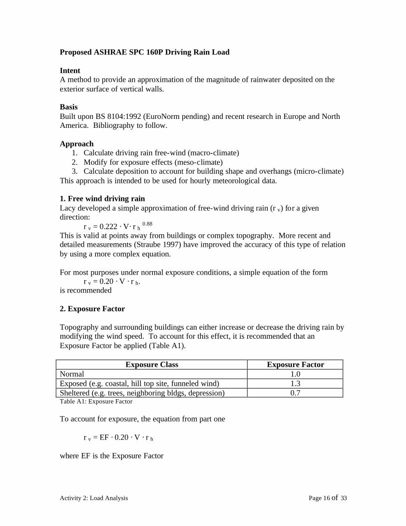

10
10 10
10
Plan View of Building
10 05 10
04
Flat Roof
035 035
05
Pitched Roof Deposition Factors for Windward Walls
Hence the final equation becomes
rbv = EF middot DFmiddot HF middot 020 middot V middot cos q middot r h
where EF is the Exposure Factor DF is the Deposition Factor HF is the Height Factor V is the hourly average wind velocity at 10 m q is the angle between the wind direction and the perpendicular to the wall r h is the horizontal rainfall intensity (mmhr) rbv is the amount of rain deposition on a vertical wall (kgm2hr)
Activity 2 Load Analysis Page 18 of 33
Appendix A
For tall buildings the velocity of the free-wind at the height of interest on the building should be accounted for The wind velocity changes with height according to
V(z) = V10 (z10)a
WhereV(z) is the wind velocity (ms) at a height z (m) above grade V10 is the velocity at the standard height of 10 m above grade and a is the gradient exponent typically 010 for open coastal areas 020-025 for suburban and as much as 04 for built-up urban areas Reference can be made to any wind load code for more detail In lieu of more detailed info an exponent of 02 is recommended
The adjusted wind velocity V(z) can be used in lieu of the height and exposure factors (HF amp EF) Otherwise the height correction factor can also be read from Table A1
Activity 2 Load Analysis Page 19 of 33
Indoor Conditions
The interior environmental conditions in residential buildings are dynamic Interior conditions change as a function of the operation of the building (mechanical ventilation systems humidifiers dehumidifiers etc) changes of the exterior climatic conditions inhabitant activities plants and the kind of objects placed in the interior environment (moisture storage) Indoor conditions that affect the heat air and moisture transport in building envelopes are
bull Temperature conditions bull Moisture content of the air (RH must be used carefully) bull Internal pressures bull Thermal sources bull Moisture sources
In nearly all cases operation of buildings is better controlled thermally than in any other way A thermostat is installed in every home allowing better control of the air space
A significant amount of moisture can be produced internally and intentional means of removing that moisture do not exist most of the time Usually water vapor is removed by air change either by natural air leakage through the building envelope or by mechanical vent ilation systems Another mechanism to remove excess water vapor is to employ some kind of dehumidification equipment with designed capacity for interior moisture production loads The obvious approach to maintain good indoor air quality is to control the level of moisture in the interior air The most cost-effective way to achieve this is to control moisture at the source
Sources of Moisture
There are many sources of moisture that can increase the amount of water in the building interior Some of these sources have nothing to do with the general operation of the building such as the construction moisture content of the building materials water table levelwater and vapor ingress from the ground and basement and crawlspace walls storing and transporting large quantities of water to the interior Wind driven rain and water penetration of the building envelope exterior and interior elements may allow seasonal storage effects Most of the time each source is independent of the other but combined together they may account for significant amount of available water In Denmark worked carried out by Kohl (1986) grouped the different sources of moisture production in dwellings as
Activity 2 Load Analysis Page 20 of 33
bull Transpiration from human body bull Evaporation from plants bull Personal hygiene such as bathing bull Cleaning of dwellings bull Washing up bull Laundering and subsequent drying bull Cooking
People as Moisture Sources
Inhabitants and their use of the building may provide a significant amount of water They may not necessarily be the largest source all the time Table 3 from a recent publication by LBNL shows the distribution of moisture loads for various activities in terms of pints of water per day Figure 214 plots out the amount of water that a specific activity may produce in liters
Table 3 Moisture Sources
Activity 2 Load Analysis Page 21 of 33
Figure 214 Water production (BSI Richard L Quirouette)
In general open literature data for a family of four give values of 35 kgday (77 lbsday) of moisture release from our body plants contribute 046 kgday (10 lbday) personal hygiene about 05 kgday (11 lbday) (family of four about 13 kgday or 29 lbsday) contributions due to house cleaning about 02 kgday (04 lbday) washing up approximately 04 kgday (09 lbday) laundry and drying anywhere from 01 kgday to 18 kgday (02-40 lbsday) cooking approximately 0897 kgday (2 lbsday) If these are all summed up a typical family of 4 may produce 4 to 14 kgday (9-31 lbsday) of moisture This numbers can be compared to numbers given by NRCan for a typical household four people of up to 160 liters (42 gallons) of water into the air each month Add to that other common sources of moisturemdashfrom long showers to leaky plumbingmdashand itrsquos easy to see how homes can suffer from poor air quality and major structural problems due to excessive moisture In addition health experts know that fungi mold and dust mites flourish in damp areas and can cause health problems such as allergies and asthma Having the right moisture level in onersquos house means greater energy fitness savings in home repairs and better health for years to come
Gas appliances can release up to 13 kgday (3 lbsday) saunas and hot tubs can also release significant amounts of water to the inside of the house as can drying of firewood indoors
Activity 2 Load Analysis Page 22 of 33
How is the interior environment affected in Minnesota
Indoor Conditions
The interior environmental conditions in residential buildings are dynamic Interior conditions change as a function of the operation of the building (mechanical ventilation systems humidifiers dehumidifiers etc) changes of the exterior climatic conditions inhabitant activities plants and the kind of objects placed in the interior environment (moisture storage) A significant amount of moisture can be produced internally and a means of removing that moisture should exist Usually water vapor is removed by air change either by natural air leakage through the building envelope or by mechanical ventilation systems Another mechanism to remove excess water vapor is to employ some kind of dehumidification equipment with designed capacity for interior moisture production loads The obvious approach to maintain good indoor air quality is to control the level of moisture in the interior air The most cost-effective way to achieve this is to control moisture at the source
ASHRAE recommends that indoor temperatures during the winter months be maintained between 68 and 75deg F and indoor temperatures during the summer months should be between 73 and 79deg F In practice complaints may occur with any temperature not maintained at 72deg F with some air circulation Relative humidity (RH) measures the amount of moisture in the air ASHRAE recommends RH be maintained between 30 and 60 for indoor environments RH below 30 can cause drying of the mucous membranes and discomfort for many people RH above 60 for extended time periods promotes indoor microbial growth
HVAC systems are designed to supply fresh air into the occupied space supplying fresh air into the building and diluting contaminants and therefore preventing buildup ASHRAE specifies the minimum amount of outside air supplied to an occupied building as 20 cubic feet per minute (CFM) per person in each occupied zone If the HVAC system is shut down overnight the system should be started at least one hour before occupancy to provide adequate ventilation Other contributors to stale and poorly mixed air include poor location of supply and exhaust air diffusers improper building or system design (often caused by change of building occupancy from original design configuration with inadequate attention during remodeling) or indoor structures that prevent free movement of air
Carbon monoxide (CO) is a common result of the presence of or proximity to sources of combustion It is present to some degree whenever fuel-operated systems are used High levels are an immediate threat to life Lower levels are a cause for health concern Concentrations should be ma intained as close to undetectable as possible
Activity 2 Load Analysis Page 23 of 33
Interior Environment Approach (This Project)
INTRODUCTION
A recent paper (TenWolde and Walker 2001) describes a state-of-the-art methodology to obtain the interior environmental conditions in terms of an analysis approach and design values Hygrothermal models require the inputs of interior environmental conditions and are extremely sensitive to the assumed moisture boundary conditions For instance during winter the moisture conditions in walls depend greatly on the indoor humidity conditions (TenWolde et al 1995) Thus a consistent approach to moisture design demands a consistent framework for design assumptions or assumed ldquoloadsrdquo The question whether or not design features such as vapor retarders or ventilation systems are necessary cannot be answered unless there is a consensus definition of the interior and exterior moisture boundary conditions that the building is expected to be able to sustain without negative consequences to itself or its inhabitants No standardized methodology for moisture design exists as yet but ASHRAE Standard Committee 160P Design Criteria for Moisture Control in Buildings is attempting to formulate appropriate design assumptions for moisture design analysis and criteria for acceptable performance The ASHRAE 160P committee is trying to arrive at design loads despite a general lack of data and information The committee is formulating several research projects to obtain better data and they will recommend these projects for funding by ASHRAE
According to TenWolde and Walker (2001) the SPC 160P standard will include interior design loads (temperature humidity and air pressure) as well as exterior design loads (temperature humidity and rain) Although it is common to impose very stringent criteria for structural design because of safety concerns moisture damage usually occurs over a long period of time and usually has less disastrous although sometimes costly consequences A consensus is beginning to emerge that a 10 likelihood of failure is an appropriate level in building moisture design analysis and we will use this for the purposes of this paper The definition of failure will also be addressed in ASHRAE Standard 160P
In a moisture analysis for building envelope design the choice of indoor environmental conditions is extremely important especially for buildings in cold climates Several European countries have defined Indoor Climate Classes For instance Tammes and Vos (1980) describe four climate cla sses for use in the Netherlands based on interior vapor pressure ranges This approach requires a different definition for each climate and does not account for large seasonal changes Sanders (1996) and the IEA Annex 24 take a different approach and define four climate classes on the basis of three critical indoor vapor pressures or ldquopivot pointsrdquo These pivot points are related to the occurrence of condensation in a north-facing wall net annual moisture accumulation in a north-facing wall or net annual moisture accumulation in a flat roof These pivot points depend on construction and climate
According to TenWolde and Walker (2001) the approached favored within SPC 160P is to be independent of construction type but will include the influences of ventilation and
Activity 2 Load Analysis Page 24 of 33
air-conditioning equipment as well as controls that may or may not be part of the building design In residential buildings in Minnesota indoor humidity is rarely explicitly controlled During winter conditions the indoor humidity depends on a combination of sources (such as people and foundation moisture) and building ventilation In some extreme climates (such as Minnesota) houses are humidified during the winter In that case an estimate must be made for this additional moisture generation rate For summer conditions there is the added complication of air conditioner and dehumidifier operation for the whole house or individual rooms Unfortunately the moisture removal performance of these devices is highly variable and depends on a host of factors that cannot easily be dealt with during the design process
DESIGN INDOOR HUMIDITY FOR HEATING
Humidity of indoor air is the result of a balance between moisture gains moisture removal from the building and net moisture exchange with hygroscopic materials inside the building TenWolde (1994a 1994b) showed that moisture storage in residences stabilizes the indoor humidity and that daily or even weekly averages can be used for the purpose of building moisture analysis Ignoring storage and using time-averaged values for the other parameters allows the determination of the indoor vapor pressure
P matm sPi = Po + (1)062198mv
where Pi = indoor vapor pressure in Hg (Pa) Po = outdoor vapor pressure in Hg (Pa) P atm = atmospheric pressure in Hg (Pa) ms = moisture source rate lbh (kgs) mv = ventilation rate lbh (kgs)
The ventilation rate for residential buildings is often expressed in terms of air changes per hour rather than as a mass flow rate The mass flow rate can be obtained from the air change rate using Equation 2
rVI mv = (2)
n
where r = air density lbft3 (kgm3) V = building volume ft3 (m3) I = air exchange rate 1h n = 1 in IP units 3600 sh in SI units
Activity 2 Load Analysis Page 25 of 33
Combining Equations 1 and 2 with the assumption of a standard atmospheric pressure of 299 in Hg (1013 kPa) and air density of 0075 lbft3 (12 kgm3) yields a simple equation
cmspi = po + (3)VI
where c = 641 in Hg ft3lb (489 times 105 m2s2)
The moisture source term in Equation 1 includes both generation (eg people) and dehumidification If dehumidification exceeds the rate at which moisture is added this term becomes negative In this project we adopted the equations above but also accounted for the transient moisture capacity of the air The air was allowed to be influenced by the previous hour condition In addition humidification was allowed to bring the relative humidity to either 15 or until surface condensation appeared on a window with a U value of 035 (IP) While it is well understood that windows have a multi-dimensional distinct distribution of heat flow this uniform U value approach of 035 allowed additional sophistication than that proposed in the ASHRAE 160P Standard and is expected to give values that are a closer representation to reality It is a fact that people limitcontrol their humidification system whenever vapor condenses on windows
Table 4 shows measured and established data from Christian (1993) and TenWolde (1988 1994) In this project three floor areas were used 1400 ft3 2000 ft3
and 2457 ft3 The two exterior climates (International Falls and Minneapolis) were entered into existing software developed at ORNL that determines the interior environmental conditions
Table 4 Daily Moisture Production (TenWolde and Walker 2001)
Activity 2 Load Analysis Page 26 of 33
Figures 215 through 220 show the influence of ventilation on the interior conditions for the city of Minneapolis MN for three seasons Winter spring and summer conditions were investigated for the corresponding months of January April and July
Figures 215 217 and 219 show average monthly local temperatures and relative humidity for a period of 30 years Figures 216 218 and 220 show the interior relative humidity as a function of RH and 3 levels of moisture production rates of 5kgday 10kgday and 20kgday (13 26 and 53 galday) The setpoint temperature and relative humidities were chosen from the 30 year average conditions shown in Figures 215 217 and 219
For a residence of 2457 ft2 it is evident that in January with the exception of a very low moisture production rate of 5 kgday the interior relative humidity can be high enough to lead to mold growth on wall surfaces and condensation on windows At a ventilation rate of 025 ACH center of room relative humidities easily exceed 40 This will result in condensation on typical glazing and result in mold growth at exterior walls where the gypsum board surface RH will exceed 80 However at a ventilation rate of 035 ACH interior relative humidities will remain in the 20 to 30 range avoiding window condensation and mold However with typical building envelope tightness average air change rates of 035 ACH cannot be achieved Similar behavior is demonstrated for April where even higher interior relative humidities were found
From these results one can observe that under normal building operating conditions with a family of 4 the interior relative humidity becomes prohibitively large without an appropriate mechanical ventilation system that maintains ACH rates at 035 (for a large part of the year)
Activity 2 Load Analysis Page 27 of 33
80 0
January Month RH January Monthly T
Minneapolis MN
1960 1970 1980 1990
76 -4
72 -8
68 -12
64 -16
Rea
ltive
Hu
mid
ity (
)
Tem
pera
ture
( oC
)
60 -20
Figure 215 Monthly Average Exterior T and RH for January (Minneapolis)
Minneapolis Residence 2457 sf
0
20
40
60
80
100
0 05 1 15 2 25 3
Air Changes Per Hour
Inte
rior
RH
low (5 kgday) average (10 kgday) high (20kgday)
Moisture Production Rate
Minneapolis Jan Outside Air -10 C70RH
Figure 216 Effect of Ventilation and Moisture Production on Interior RH (January)
Activity 2 Load Analysis Page 28 of 33
80 12
1960 1970 1980 1990
April Month RH April Monthly T
Minneapolis MN
Rea
ltive
Hu
mid
ity (
)
10
70
8
6
60
4
Tem
pera
ture
( oC
)
50 2
Figure 217 Monthly Average Exterior T and RH for April (Minneapolis)
Minneapolis Residence 2457 sf
0
20
40
60
80
100
0 05 1 15 2 25 3
Air Changes Per Hour
Inte
rior
RH low (5 kgday)
average (10 kgday) high (20kgday)
Moisture Production Rate
Minneapolis Apr Outside Air 8 C60RH
Figure 218 Effect of Ventilation and Moisture Production on Interior RH (April)
Activity 2 Load Analysis Page 29 of 33
80 26 July Month RH July Monthly T
1960 1970 1980 1990
Rea
ltive
Hum
idity
()
24
70
22
60
20
50 18
Tem
per
atur
e ( o
C)
Figure 219 Monthly Average Exterior T and RH for July (Minneapolis)
Minneapolis Residence 2457 sf
0
20
40
60
80
100
0 05 1 15 2 25 3
Air Changes Per Hour
Inte
rior
RH
low (5 kgday) average (10 kgday) high (20kgday)
Moisture Production Rate
Minneapolis Jul Outside Air 23 C65RH
Figure 220 Effect of Ventilation and Moisture Production on Interior RH (July)
Activity 2 Load Analysis Page 30 of 33
In Figures 221 through 224 the corresponding instantaneous values of the interior RH versus time in hours (0 is January) is plotted out for a period of two years (10 cold and 10 hot year) The moving average is shown as a weekly averaged number every 168 hours (7 days) Results clearly show the effects of moisture source rates and air exchange rate Permeable wall systems (Category 2) here are shown to not be able to appropriately dilute the moisture production rates of a family of 4
100
090
080
070
Series1060
RH
(-)
050 168 per Mov Avg
040 (Series1)
030
020
010
000 1 2865 5729 8593 11457 14321 17185
Time (hr)
Figure 221 Interior RH (Minneapolis) w 5 kgday moisture source (3 ACH)
100
090
080
070
060 Series1
RH
(-)
040
050 168 per Mov Avg (Series1)
030
020
010
000 1 2865 5729 8593 11457 14321 17185
Time (hr)
Figure 222 Interior RH (Minneapolis) w 5 kgday moisture source (035 ACH 1 gm3)
Activity 2 Load Analysis Page 31 of 33
RH
(-)
100
090
080
070
060 Series1
040
050 168 per Mov Avg (Series1)
030
020
010
000 1 2865 5729 8593 11457 14321 17185
Time (hr)
Figure 223 Interior RH (Minneapolis) w 20 kgday moisture source (3 ACH)
100
090
080
070
Series1060
RH
(-)
030
040
050 168 per Mov Avg (Series1)
020
010
000 1 2865 5729 8593 11457 14321 17185
Time (hr)
Figure 224 Interior RH (Minneapolis) w 20 kgday moisture source (03 ACH 417 gm)
Activity 2 Load Analysis Page 32 of 33
List of Figures
Figure 21 Geographic LocationYearly Rainfall (Blue- High Yellow-Low) 2 Figure 22 Average Annual Precipitation (Minnesota) 3 Figure 23 Average Yearly Temp erature in Minnesota 4 Figure 24 Minneapolis Climatic Conditions 5 Figure 25 International Falls Climatic Conditions 6 Figure 26 Vapor Pressure Distribution for Minneapolis 7 Figure 27 Vapor Pressure Distribution for International Falls 8 Figure 28 Wind Speed Rose for Minneapolis 12 Figure 29 Rain Rose for Minneapolis 12 Figure 210 Wind Speed Rose for International Falls 13 Figure 211 Rain Rose for International Falls 13 Figure 212a Possible Rain (before effect of Wind) for Minneapolis 14 Figure 213a Possible Rain (before effect of Wind) for International Falls 15 Figure 214 Water production (BSI Richard L Quirouette) 22 Figure 215 Monthly Average Exterior T and RH for January (Minneapolis) 28 Figure 216 Effect of Ventilation and Moisture Production on Interior RH (January) 28 Figure 217 Monthly Average Exterior T and RH for April (Minneapolis) 29 Figure 218 Effect of Ventilation and Moisture Production on Interior RH (April) 29 Figure 219 Monthly Average Exterior T and RH for July (Minneapolis) 30 Figure 220 Effect of Ventilation and Moisture Production on Interior RH (July) 30 Figure 221 Interio r RH (Minneapolis) w 5 kgday moisture source (3 ACH) 31 Figure 222 Interior RH (Minneapolis) w 5 kgday moisture source (035 ACH 1 gm3) 31 Figure 223 Interior RH (Minneapolis) w 20 kgday moisture source (3 ACH) 32 Figure 224 Interior RH (Minneapolis) w 20 kgday moisture source (03 ACH 417 gm) 32
List of Tables
Table 1 Synopsis of Hygric Loads for Minneapolis 9 Table 2 Synopsis of Hygric Loads for International Falls 10 Table 3 Moisture Sources 21 Table 4 Daily Moisture Production (TenWolde and Walker 2001) 26
Activity 2 Load Analysis Page 33 of 33

Indoor Conditions
The interior environmental conditions in residential buildings are dynamic Interior conditions change as a function of the operation of the building (mechanical ventilation systems humidifiers dehumidifiers etc) changes of the exterior climatic conditions inhabitant activities plants and the kind of objects placed in the interior environment (moisture storage) Indoor conditions that affect the heat air and moisture transport in building envelopes are
bull Temperature conditions bull Moisture content of the air (RH must be used carefully) bull Internal pressures bull Thermal sources bull Moisture sources
In nearly all cases operation of buildings is better controlled thermally than in any other way A thermostat is installed in every home allowing better control of the air space
A significant amount of moisture can be produced internally and intentional means of removing that moisture do not exist most of the time Usually water vapor is removed by air change either by natural air leakage through the building envelope or by mechanical vent ilation systems Another mechanism to remove excess water vapor is to employ some kind of dehumidification equipment with designed capacity for interior moisture production loads The obvious approach to maintain good indoor air quality is to control the level of moisture in the interior air The most cost-effective way to achieve this is to control moisture at the source
Sources of Moisture
There are many sources of moisture that can increase the amount of water in the building interior Some of these sources have nothing to do with the general operation of the building such as the construction moisture content of the building materials water table levelwater and vapor ingress from the ground and basement and crawlspace walls storing and transporting large quantities of water to the interior Wind driven rain and water penetration of the building envelope exterior and interior elements may allow seasonal storage effects Most of the time each source is independent of the other but combined together they may account for significant amount of available water In Denmark worked carried out by Kohl (1986) grouped the different sources of moisture production in dwellings as
Activity 2 Load Analysis Page 20 of 33
bull Transpiration from human body bull Evaporation from plants bull Personal hygiene such as bathing bull Cleaning of dwellings bull Washing up bull Laundering and subsequent drying bull Cooking
People as Moisture Sources
Inhabitants and their use of the building may provide a significant amount of water They may not necessarily be the largest source all the time Table 3 from a recent publication by LBNL shows the distribution of moisture loads for various activities in terms of pints of water per day Figure 214 plots out the amount of water that a specific activity may produce in liters
Table 3 Moisture Sources
Activity 2 Load Analysis Page 21 of 33
Figure 214 Water production (BSI Richard L Quirouette)
In general open literature data for a family of four give values of 35 kgday (77 lbsday) of moisture release from our body plants contribute 046 kgday (10 lbday) personal hygiene about 05 kgday (11 lbday) (family of four about 13 kgday or 29 lbsday) contributions due to house cleaning about 02 kgday (04 lbday) washing up approximately 04 kgday (09 lbday) laundry and drying anywhere from 01 kgday to 18 kgday (02-40 lbsday) cooking approximately 0897 kgday (2 lbsday) If these are all summed up a typical family of 4 may produce 4 to 14 kgday (9-31 lbsday) of moisture This numbers can be compared to numbers given by NRCan for a typical household four people of up to 160 liters (42 gallons) of water into the air each month Add to that other common sources of moisturemdashfrom long showers to leaky plumbingmdashand itrsquos easy to see how homes can suffer from poor air quality and major structural problems due to excessive moisture In addition health experts know that fungi mold and dust mites flourish in damp areas and can cause health problems such as allergies and asthma Having the right moisture level in onersquos house means greater energy fitness savings in home repairs and better health for years to come
Gas appliances can release up to 13 kgday (3 lbsday) saunas and hot tubs can also release significant amounts of water to the inside of the house as can drying of firewood indoors
Activity 2 Load Analysis Page 22 of 33
How is the interior environment affected in Minnesota
Indoor Conditions
The interior environmental conditions in residential buildings are dynamic Interior conditions change as a function of the operation of the building (mechanical ventilation systems humidifiers dehumidifiers etc) changes of the exterior climatic conditions inhabitant activities plants and the kind of objects placed in the interior environment (moisture storage) A significant amount of moisture can be produced internally and a means of removing that moisture should exist Usually water vapor is removed by air change either by natural air leakage through the building envelope or by mechanical ventilation systems Another mechanism to remove excess water vapor is to employ some kind of dehumidification equipment with designed capacity for interior moisture production loads The obvious approach to maintain good indoor air quality is to control the level of moisture in the interior air The most cost-effective way to achieve this is to control moisture at the source
ASHRAE recommends that indoor temperatures during the winter months be maintained between 68 and 75deg F and indoor temperatures during the summer months should be between 73 and 79deg F In practice complaints may occur with any temperature not maintained at 72deg F with some air circulation Relative humidity (RH) measures the amount of moisture in the air ASHRAE recommends RH be maintained between 30 and 60 for indoor environments RH below 30 can cause drying of the mucous membranes and discomfort for many people RH above 60 for extended time periods promotes indoor microbial growth
HVAC systems are designed to supply fresh air into the occupied space supplying fresh air into the building and diluting contaminants and therefore preventing buildup ASHRAE specifies the minimum amount of outside air supplied to an occupied building as 20 cubic feet per minute (CFM) per person in each occupied zone If the HVAC system is shut down overnight the system should be started at least one hour before occupancy to provide adequate ventilation Other contributors to stale and poorly mixed air include poor location of supply and exhaust air diffusers improper building or system design (often caused by change of building occupancy from original design configuration with inadequate attention during remodeling) or indoor structures that prevent free movement of air
Carbon monoxide (CO) is a common result of the presence of or proximity to sources of combustion It is present to some degree whenever fuel-operated systems are used High levels are an immediate threat to life Lower levels are a cause for health concern Concentrations should be ma intained as close to undetectable as possible
Activity 2 Load Analysis Page 23 of 33
Interior Environment Approach (This Project)
INTRODUCTION
A recent paper (TenWolde and Walker 2001) describes a state-of-the-art methodology to obtain the interior environmental conditions in terms of an analysis approach and design values Hygrothermal models require the inputs of interior environmental conditions and are extremely sensitive to the assumed moisture boundary conditions For instance during winter the moisture conditions in walls depend greatly on the indoor humidity conditions (TenWolde et al 1995) Thus a consistent approach to moisture design demands a consistent framework for design assumptions or assumed ldquoloadsrdquo The question whether or not design features such as vapor retarders or ventilation systems are necessary cannot be answered unless there is a consensus definition of the interior and exterior moisture boundary conditions that the building is expected to be able to sustain without negative consequences to itself or its inhabitants No standardized methodology for moisture design exists as yet but ASHRAE Standard Committee 160P Design Criteria for Moisture Control in Buildings is attempting to formulate appropriate design assumptions for moisture design analysis and criteria for acceptable performance The ASHRAE 160P committee is trying to arrive at design loads despite a general lack of data and information The committee is formulating several research projects to obtain better data and they will recommend these projects for funding by ASHRAE
According to TenWolde and Walker (2001) the SPC 160P standard will include interior design loads (temperature humidity and air pressure) as well as exterior design loads (temperature humidity and rain) Although it is common to impose very stringent criteria for structural design because of safety concerns moisture damage usually occurs over a long period of time and usually has less disastrous although sometimes costly consequences A consensus is beginning to emerge that a 10 likelihood of failure is an appropriate level in building moisture design analysis and we will use this for the purposes of this paper The definition of failure will also be addressed in ASHRAE Standard 160P
In a moisture analysis for building envelope design the choice of indoor environmental conditions is extremely important especially for buildings in cold climates Several European countries have defined Indoor Climate Classes For instance Tammes and Vos (1980) describe four climate cla sses for use in the Netherlands based on interior vapor pressure ranges This approach requires a different definition for each climate and does not account for large seasonal changes Sanders (1996) and the IEA Annex 24 take a different approach and define four climate classes on the basis of three critical indoor vapor pressures or ldquopivot pointsrdquo These pivot points are related to the occurrence of condensation in a north-facing wall net annual moisture accumulation in a north-facing wall or net annual moisture accumulation in a flat roof These pivot points depend on construction and climate
According to TenWolde and Walker (2001) the approached favored within SPC 160P is to be independent of construction type but will include the influences of ventilation and
Activity 2 Load Analysis Page 24 of 33
air-conditioning equipment as well as controls that may or may not be part of the building design In residential buildings in Minnesota indoor humidity is rarely explicitly controlled During winter conditions the indoor humidity depends on a combination of sources (such as people and foundation moisture) and building ventilation In some extreme climates (such as Minnesota) houses are humidified during the winter In that case an estimate must be made for this additional moisture generation rate For summer conditions there is the added complication of air conditioner and dehumidifier operation for the whole house or individual rooms Unfortunately the moisture removal performance of these devices is highly variable and depends on a host of factors that cannot easily be dealt with during the design process
DESIGN INDOOR HUMIDITY FOR HEATING
Humidity of indoor air is the result of a balance between moisture gains moisture removal from the building and net moisture exchange with hygroscopic materials inside the building TenWolde (1994a 1994b) showed that moisture storage in residences stabilizes the indoor humidity and that daily or even weekly averages can be used for the purpose of building moisture analysis Ignoring storage and using time-averaged values for the other parameters allows the determination of the indoor vapor pressure
P matm sPi = Po + (1)062198mv
where Pi = indoor vapor pressure in Hg (Pa) Po = outdoor vapor pressure in Hg (Pa) P atm = atmospheric pressure in Hg (Pa) ms = moisture source rate lbh (kgs) mv = ventilation rate lbh (kgs)
The ventilation rate for residential buildings is often expressed in terms of air changes per hour rather than as a mass flow rate The mass flow rate can be obtained from the air change rate using Equation 2
rVI mv = (2)
n
where r = air density lbft3 (kgm3) V = building volume ft3 (m3) I = air exchange rate 1h n = 1 in IP units 3600 sh in SI units
Activity 2 Load Analysis Page 25 of 33
Combining Equations 1 and 2 with the assumption of a standard atmospheric pressure of 299 in Hg (1013 kPa) and air density of 0075 lbft3 (12 kgm3) yields a simple equation
cmspi = po + (3)VI
where c = 641 in Hg ft3lb (489 times 105 m2s2)
The moisture source term in Equation 1 includes both generation (eg people) and dehumidification If dehumidification exceeds the rate at which moisture is added this term becomes negative In this project we adopted the equations above but also accounted for the transient moisture capacity of the air The air was allowed to be influenced by the previous hour condition In addition humidification was allowed to bring the relative humidity to either 15 or until surface condensation appeared on a window with a U value of 035 (IP) While it is well understood that windows have a multi-dimensional distinct distribution of heat flow this uniform U value approach of 035 allowed additional sophistication than that proposed in the ASHRAE 160P Standard and is expected to give values that are a closer representation to reality It is a fact that people limitcontrol their humidification system whenever vapor condenses on windows
Table 4 shows measured and established data from Christian (1993) and TenWolde (1988 1994) In this project three floor areas were used 1400 ft3 2000 ft3
and 2457 ft3 The two exterior climates (International Falls and Minneapolis) were entered into existing software developed at ORNL that determines the interior environmental conditions
Table 4 Daily Moisture Production (TenWolde and Walker 2001)
Activity 2 Load Analysis Page 26 of 33
Figures 215 through 220 show the influence of ventilation on the interior conditions for the city of Minneapolis MN for three seasons Winter spring and summer conditions were investigated for the corresponding months of January April and July
Figures 215 217 and 219 show average monthly local temperatures and relative humidity for a period of 30 years Figures 216 218 and 220 show the interior relative humidity as a function of RH and 3 levels of moisture production rates of 5kgday 10kgday and 20kgday (13 26 and 53 galday) The setpoint temperature and relative humidities were chosen from the 30 year average conditions shown in Figures 215 217 and 219
For a residence of 2457 ft2 it is evident that in January with the exception of a very low moisture production rate of 5 kgday the interior relative humidity can be high enough to lead to mold growth on wall surfaces and condensation on windows At a ventilation rate of 025 ACH center of room relative humidities easily exceed 40 This will result in condensation on typical glazing and result in mold growth at exterior walls where the gypsum board surface RH will exceed 80 However at a ventilation rate of 035 ACH interior relative humidities will remain in the 20 to 30 range avoiding window condensation and mold However with typical building envelope tightness average air change rates of 035 ACH cannot be achieved Similar behavior is demonstrated for April where even higher interior relative humidities were found
From these results one can observe that under normal building operating conditions with a family of 4 the interior relative humidity becomes prohibitively large without an appropriate mechanical ventilation system that maintains ACH rates at 035 (for a large part of the year)
Activity 2 Load Analysis Page 27 of 33
80 0
January Month RH January Monthly T
Minneapolis MN
1960 1970 1980 1990
76 -4
72 -8
68 -12
64 -16
Rea
ltive
Hu
mid
ity (
)
Tem
pera
ture
( oC
)
60 -20
Figure 215 Monthly Average Exterior T and RH for January (Minneapolis)
Minneapolis Residence 2457 sf
0
20
40
60
80
100
0 05 1 15 2 25 3
Air Changes Per Hour
Inte
rior
RH
low (5 kgday) average (10 kgday) high (20kgday)
Moisture Production Rate
Minneapolis Jan Outside Air -10 C70RH
Figure 216 Effect of Ventilation and Moisture Production on Interior RH (January)
Activity 2 Load Analysis Page 28 of 33
80 12
1960 1970 1980 1990
April Month RH April Monthly T
Minneapolis MN
Rea
ltive
Hu
mid
ity (
)
10
70
8
6
60
4
Tem
pera
ture
( oC
)
50 2
Figure 217 Monthly Average Exterior T and RH for April (Minneapolis)
Minneapolis Residence 2457 sf
0
20
40
60
80
100
0 05 1 15 2 25 3
Air Changes Per Hour
Inte
rior
RH low (5 kgday)
average (10 kgday) high (20kgday)
Moisture Production Rate
Minneapolis Apr Outside Air 8 C60RH
Figure 218 Effect of Ventilation and Moisture Production on Interior RH (April)
Activity 2 Load Analysis Page 29 of 33
80 26 July Month RH July Monthly T
1960 1970 1980 1990
Rea
ltive
Hum
idity
()
24
70
22
60
20
50 18
Tem
per
atur
e ( o
C)
Figure 219 Monthly Average Exterior T and RH for July (Minneapolis)
Minneapolis Residence 2457 sf
0
20
40
60
80
100
0 05 1 15 2 25 3
Air Changes Per Hour
Inte
rior
RH
low (5 kgday) average (10 kgday) high (20kgday)
Moisture Production Rate
Minneapolis Jul Outside Air 23 C65RH
Figure 220 Effect of Ventilation and Moisture Production on Interior RH (July)
Activity 2 Load Analysis Page 30 of 33
In Figures 221 through 224 the corresponding instantaneous values of the interior RH versus time in hours (0 is January) is plotted out for a period of two years (10 cold and 10 hot year) The moving average is shown as a weekly averaged number every 168 hours (7 days) Results clearly show the effects of moisture source rates and air exchange rate Permeable wall systems (Category 2) here are shown to not be able to appropriately dilute the moisture production rates of a family of 4
100
090
080
070
Series1060
RH
(-)
050 168 per Mov Avg
040 (Series1)
030
020
010
000 1 2865 5729 8593 11457 14321 17185
Time (hr)
Figure 221 Interior RH (Minneapolis) w 5 kgday moisture source (3 ACH)
100
090
080
070
060 Series1
RH
(-)
040
050 168 per Mov Avg (Series1)
030
020
010
000 1 2865 5729 8593 11457 14321 17185
Time (hr)
Figure 222 Interior RH (Minneapolis) w 5 kgday moisture source (035 ACH 1 gm3)
Activity 2 Load Analysis Page 31 of 33
RH
(-)
100
090
080
070
060 Series1
040
050 168 per Mov Avg (Series1)
030
020
010
000 1 2865 5729 8593 11457 14321 17185
Time (hr)
Figure 223 Interior RH (Minneapolis) w 20 kgday moisture source (3 ACH)
100
090
080
070
Series1060
RH
(-)
030
040
050 168 per Mov Avg (Series1)
020
010
000 1 2865 5729 8593 11457 14321 17185
Time (hr)
Figure 224 Interior RH (Minneapolis) w 20 kgday moisture source (03 ACH 417 gm)
Activity 2 Load Analysis Page 32 of 33
List of Figures
Figure 21 Geographic LocationYearly Rainfall (Blue- High Yellow-Low) 2 Figure 22 Average Annual Precipitation (Minnesota) 3 Figure 23 Average Yearly Temp erature in Minnesota 4 Figure 24 Minneapolis Climatic Conditions 5 Figure 25 International Falls Climatic Conditions 6 Figure 26 Vapor Pressure Distribution for Minneapolis 7 Figure 27 Vapor Pressure Distribution for International Falls 8 Figure 28 Wind Speed Rose for Minneapolis 12 Figure 29 Rain Rose for Minneapolis 12 Figure 210 Wind Speed Rose for International Falls 13 Figure 211 Rain Rose for International Falls 13 Figure 212a Possible Rain (before effect of Wind) for Minneapolis 14 Figure 213a Possible Rain (before effect of Wind) for International Falls 15 Figure 214 Water production (BSI Richard L Quirouette) 22 Figure 215 Monthly Average Exterior T and RH for January (Minneapolis) 28 Figure 216 Effect of Ventilation and Moisture Production on Interior RH (January) 28 Figure 217 Monthly Average Exterior T and RH for April (Minneapolis) 29 Figure 218 Effect of Ventilation and Moisture Production on Interior RH (April) 29 Figure 219 Monthly Average Exterior T and RH for July (Minneapolis) 30 Figure 220 Effect of Ventilation and Moisture Production on Interior RH (July) 30 Figure 221 Interio r RH (Minneapolis) w 5 kgday moisture source (3 ACH) 31 Figure 222 Interior RH (Minneapolis) w 5 kgday moisture source (035 ACH 1 gm3) 31 Figure 223 Interior RH (Minneapolis) w 20 kgday moisture source (3 ACH) 32 Figure 224 Interior RH (Minneapolis) w 20 kgday moisture source (03 ACH 417 gm) 32
List of Tables
Table 1 Synopsis of Hygric Loads for Minneapolis 9 Table 2 Synopsis of Hygric Loads for International Falls 10 Table 3 Moisture Sources 21 Table 4 Daily Moisture Production (TenWolde and Walker 2001) 26
Activity 2 Load Analysis Page 33 of 33
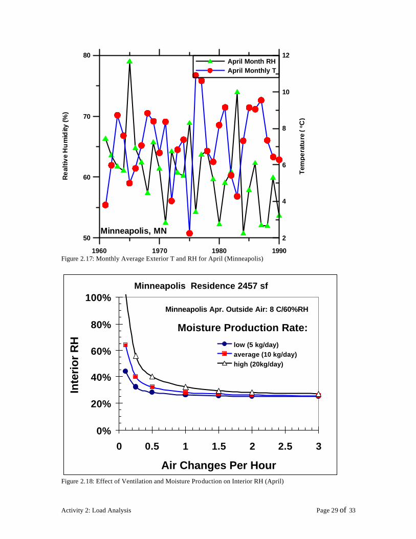

RH
(-)
100
090
080
070
060 Series1
040
050 168 per Mov Avg (Series1)
030
020
010
000 1 2865 5729 8593 11457 14321 17185
Time (hr)
Figure 223 Interior RH (Minneapolis) w 20 kgday moisture source (3 ACH)
100
090
080
070
Series1060
RH
(-)
030
040
050 168 per Mov Avg (Series1)
020
010
000 1 2865 5729 8593 11457 14321 17185
Time (hr)
Figure 224 Interior RH (Minneapolis) w 20 kgday moisture source (03 ACH 417 gm)
Activity 2 Load Analysis Page 32 of 33
List of Figures
Figure 21 Geographic LocationYearly Rainfall (Blue- High Yellow-Low) 2 Figure 22 Average Annual Precipitation (Minnesota) 3 Figure 23 Average Yearly Temp erature in Minnesota 4 Figure 24 Minneapolis Climatic Conditions 5 Figure 25 International Falls Climatic Conditions 6 Figure 26 Vapor Pressure Distribution for Minneapolis 7 Figure 27 Vapor Pressure Distribution for International Falls 8 Figure 28 Wind Speed Rose for Minneapolis 12 Figure 29 Rain Rose for Minneapolis 12 Figure 210 Wind Speed Rose for International Falls 13 Figure 211 Rain Rose for International Falls 13 Figure 212a Possible Rain (before effect of Wind) for Minneapolis 14 Figure 213a Possible Rain (before effect of Wind) for International Falls 15 Figure 214 Water production (BSI Richard L Quirouette) 22 Figure 215 Monthly Average Exterior T and RH for January (Minneapolis) 28 Figure 216 Effect of Ventilation and Moisture Production on Interior RH (January) 28 Figure 217 Monthly Average Exterior T and RH for April (Minneapolis) 29 Figure 218 Effect of Ventilation and Moisture Production on Interior RH (April) 29 Figure 219 Monthly Average Exterior T and RH for July (Minneapolis) 30 Figure 220 Effect of Ventilation and Moisture Production on Interior RH (July) 30 Figure 221 Interio r RH (Minneapolis) w 5 kgday moisture source (3 ACH) 31 Figure 222 Interior RH (Minneapolis) w 5 kgday moisture source (035 ACH 1 gm3) 31 Figure 223 Interior RH (Minneapolis) w 20 kgday moisture source (3 ACH) 32 Figure 224 Interior RH (Minneapolis) w 20 kgday moisture source (03 ACH 417 gm) 32
List of Tables
Table 1 Synopsis of Hygric Loads for Minneapolis 9 Table 2 Synopsis of Hygric Loads for International Falls 10 Table 3 Moisture Sources 21 Table 4 Daily Moisture Production (TenWolde and Walker 2001) 26
Activity 2 Load Analysis Page 33 of 33


