16
Adafruit TB6612 1.2A DC/Stepper Motor Driver Breakout Board Created by lady ada Last updated on 2016-10-01 06:35:33 PM UTC
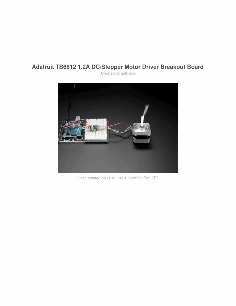
Adafruit TB6612 1.2A DC/Stepper Motor Driver Breakout BoardCreated by lady ada
Last updated on 2016-10-01 06:35:33 PM UTC
23778899
1011
12121315151515
Guide Contents
Guide ContentsOverviewPinoutsPower PinsSignal in PinsMotor Out PinsAssembly
Prepare the header strip:Add the breakout board:And Solder!
Using Stepper MotorsWiringSoftwareDownloadsFilesSchematicFabrication print
© Adafruit Industries https://learn.adafruit.com/adafruit-tb6612-h-bridge-dc-stepper-motor-driver-breakout
Page 2 of 16
Overview
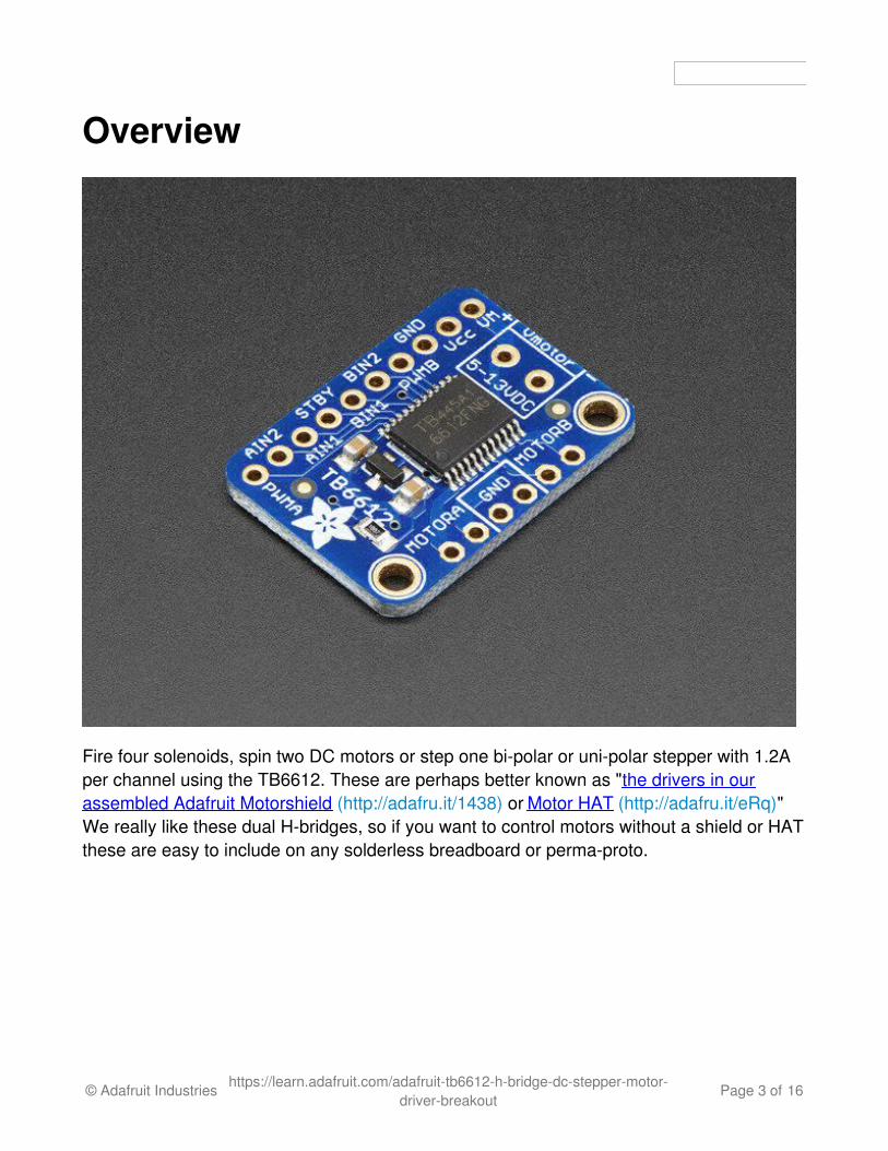
Fire four solenoids, spin two DC motors or step one bi-polar or uni-polar stepper with 1.2Aper channel using the TB6612. These are perhaps better known as "the drivers in ourassembled Adafruit Motorshield (http://adafru.it/1438) or Motor HAT (http://adafru.it/eRq)"We really like these dual H-bridges, so if you want to control motors without a shield or HATthese are easy to include on any solderless breadboard or perma-proto.
© Adafruit Industries https://learn.adafruit.com/adafruit-tb6612-h-bridge-dc-stepper-motor-driver-breakout
Page 3 of 16
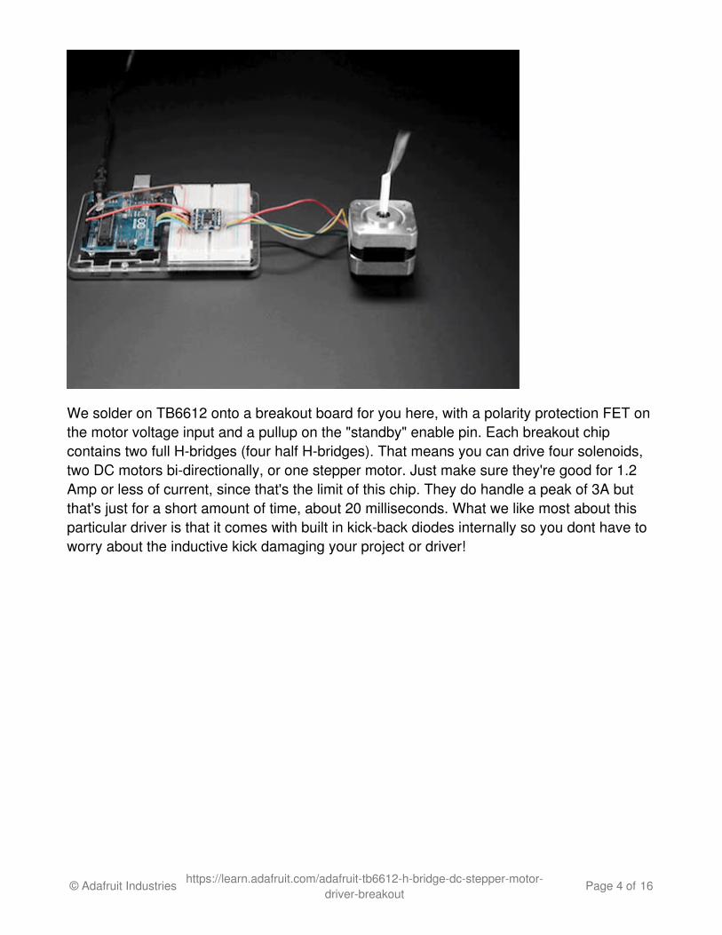
We solder on TB6612 onto a breakout board for you here, with a polarity protection FET onthe motor voltage input and a pullup on the "standby" enable pin. Each breakout chipcontains two full H-bridges (four half H-bridges). That means you can drive four solenoids,two DC motors bi-directionally, or one stepper motor. Just make sure they're good for 1.2Amp or less of current, since that's the limit of this chip. They do handle a peak of 3A butthat's just for a short amount of time, about 20 milliseconds. What we like most about thisparticular driver is that it comes with built in kick-back diodes internally so you dont have toworry about the inductive kick damaging your project or driver!
© Adafruit Industries https://learn.adafruit.com/adafruit-tb6612-h-bridge-dc-stepper-motor-driver-breakout
Page 4 of 16
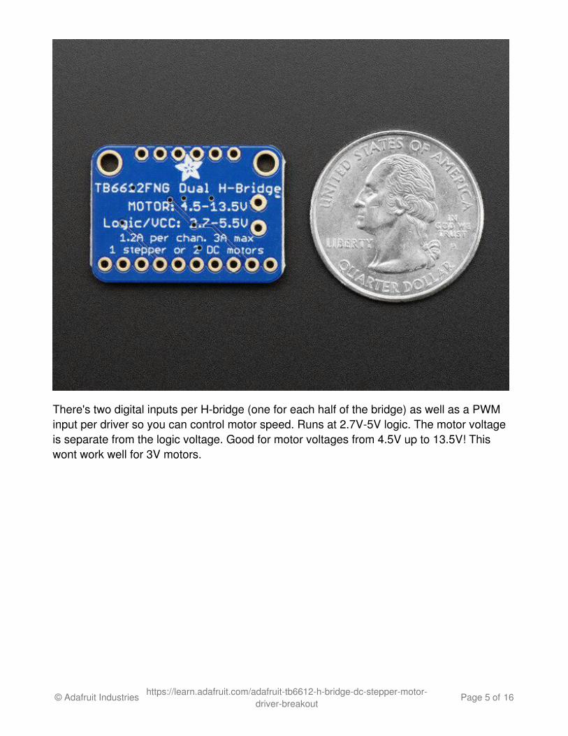
There's two digital inputs per H-bridge (one for each half of the bridge) as well as a PWMinput per driver so you can control motor speed. Runs at 2.7V-5V logic. The motor voltageis separate from the logic voltage. Good for motor voltages from 4.5V up to 13.5V! Thiswont work well for 3V motors.
© Adafruit Industries https://learn.adafruit.com/adafruit-tb6612-h-bridge-dc-stepper-motor-driver-breakout
Page 5 of 16

Comes as one assembled and tested breakout plus a small strip of header. You'll need todo some light soldering to attach the header onto the breakout PCB. Arduino, motors, andpower supply not included.
© Adafruit Industries https://learn.adafruit.com/adafruit-tb6612-h-bridge-dc-stepper-motor-driver-breakout
Page 6 of 16

Pinouts
This motor driver is a fairly simple breakout of the TB6612 motor chip, so do check out thedatasheet for the TB6612 for any details you need about pin voltage limits, capacitance,etc! (http://adafru.it/emK)
Power PinsVmotor - This is the voltage for the motors, not for the logic level. Keep this voltagebetween 4.5V and 13.5V. This power supply will get noisy so if you have a systemwith analog readings or RF other noise-sensitive parts, you may need to keep thepower supplies seperate (or filtered!)Vcc - this is the voltage for the logic levels. Set to the voltage logic you'll be using on
© Adafruit Industries https://learn.adafruit.com/adafruit-tb6612-h-bridge-dc-stepper-motor-driver-breakout
Page 7 of 16

your microcontroller. E.g. for Arduinos, 5V is probably what you want. Can be 2.7V to5.5V so good for 3V or 5V logicGND - This is the shared logic and motor ground. All grounds are connected
Signal in PinsThese are all 'Vcc logic level' inputs
INA1, INA2 - these are the two inputs to the Motor A H-bridgesPWMA - this is the PWM input for the Motor A H-bridges, if you dont need PWMcontrol, connect this to logic high.INB1, INB2 - these are the two inputs to the Motor B H-bridgesPWMB - this is the PWM input for the Motor B H-bridges, if you dont need PWMcontrol, connect this to logic high.STBY - this is the standby pin for quickly disabling both motors, pulled up to Vcc thrua 10K resistor. Connect to ground to disable.
Motor Out PinsThese are 'Vmotor level' power outputs
Motor A - these are the two outputs for motor A, controlled by INA1, INA2 and PWMAMotor B - these are the two outputs for motor B, controlled by INB1, INB2 and PWMB
© Adafruit Industries https://learn.adafruit.com/adafruit-tb6612-h-bridge-dc-stepper-motor-driver-breakout
Page 8 of 16
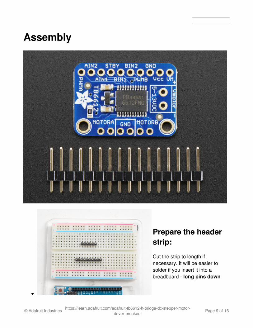
Assembly
Prepare the headerstrip:
Cut the strip to length ifnecessary. It will be easier tosolder if you insert it into abreadboard - long pins down
© Adafruit Industries https://learn.adafruit.com/adafruit-tb6612-h-bridge-dc-stepper-motor-driver-breakout
Page 9 of 16
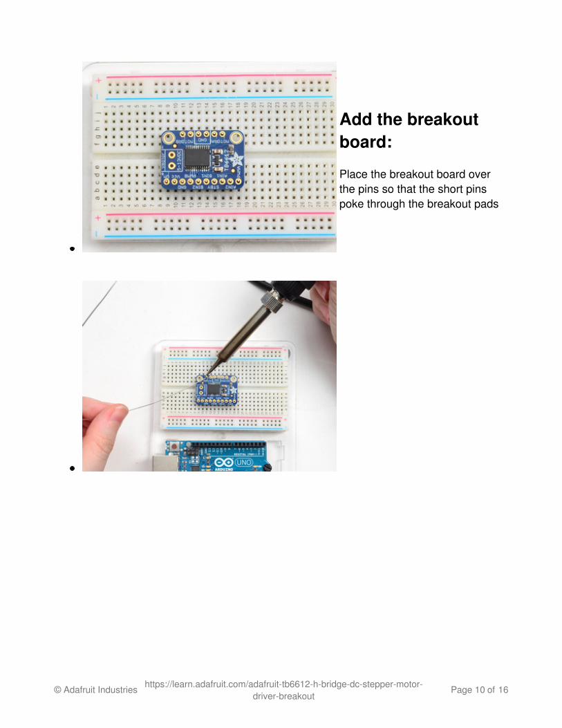
Add the breakoutboard:
Place the breakout board overthe pins so that the short pinspoke through the breakout pads
© Adafruit Industries https://learn.adafruit.com/adafruit-tb6612-h-bridge-dc-stepper-motor-driver-breakout
Page 10 of 16
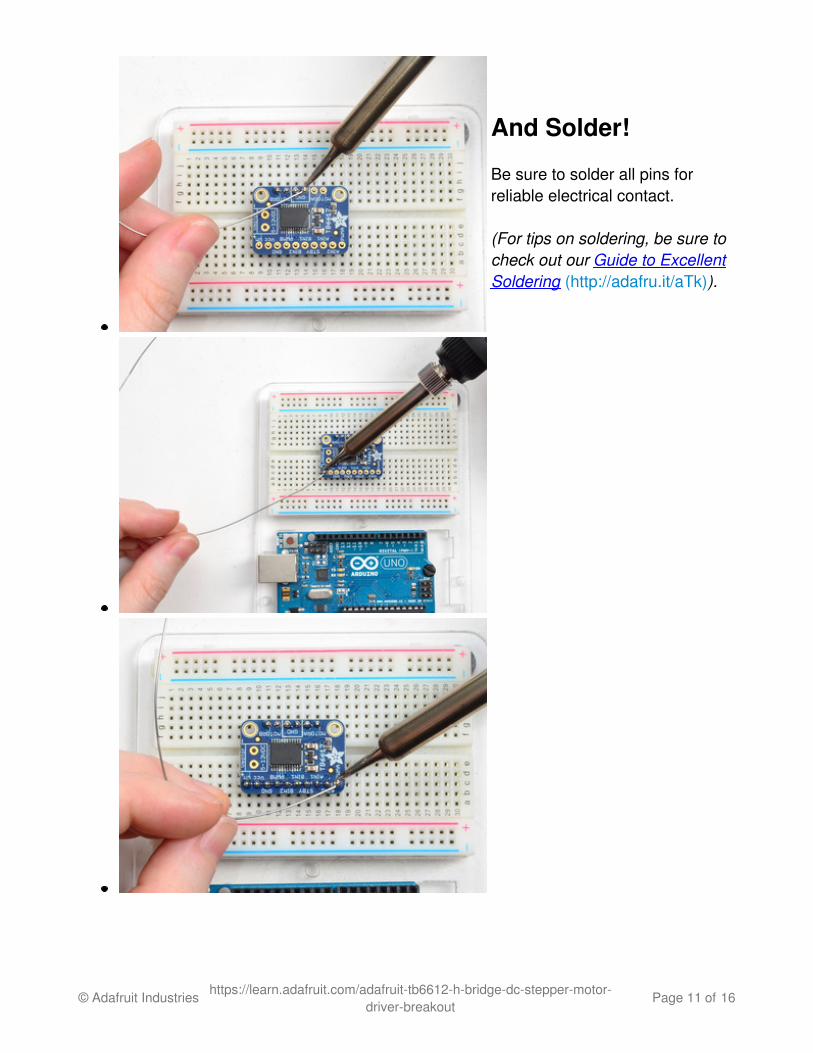
And Solder!
Be sure to solder all pins forreliable electrical contact.
(For tips on soldering, be sure tocheck out our Guide to ExcellentSoldering (http://adafru.it/aTk)).
© Adafruit Industries https://learn.adafruit.com/adafruit-tb6612-h-bridge-dc-stepper-motor-driver-breakout
Page 11 of 16

Using Stepper MotorsIn this example we'll wire up and use a bi-polar stepper motor with recommended 12Vmotor voltage, and 200 steps per rotation.
WiringWe'll wire it to a Metro, but you can use any microcontroller you like!
Connect:
Vmotor to 12V (red wire)Vcc to 5V (orange wire)GND to ground
© Adafruit Industries https://learn.adafruit.com/adafruit-tb6612-h-bridge-dc-stepper-motor-driver-breakout
Page 12 of 16

AIN2 to Digital 4AIN1 to Digital 5BIN1 to Digital 6BIN2 to Digital 7PWMA and PWMB to Vcc (orange wire)
Then hook one stepper motor coil to Motor A (red and yellow) and the second coil to MotorB (green and gray/brown). If you have another motor, you'll need to experiment a little tofigure out which wires are which coil. Check any documentation you have! You can use amultimeter to measure between wires, the ones with a small resistance between them are apair to a coil, for example. If the motor is vibrating but not spinning, check all wires areconnected and try flipping around a pair or rechecking the wire pairs.
If you have a unipolar motor, there will be a 5th or 6th wire that is the 'common' wire.Connect these wires to the GND pins in between the Motor A and B outputs on thebreakout.
Software© Adafruit Industries https://learn.adafruit.com/adafruit-tb6612-h-bridge-dc-stepper-motor-
driver-breakoutPage 13 of 16
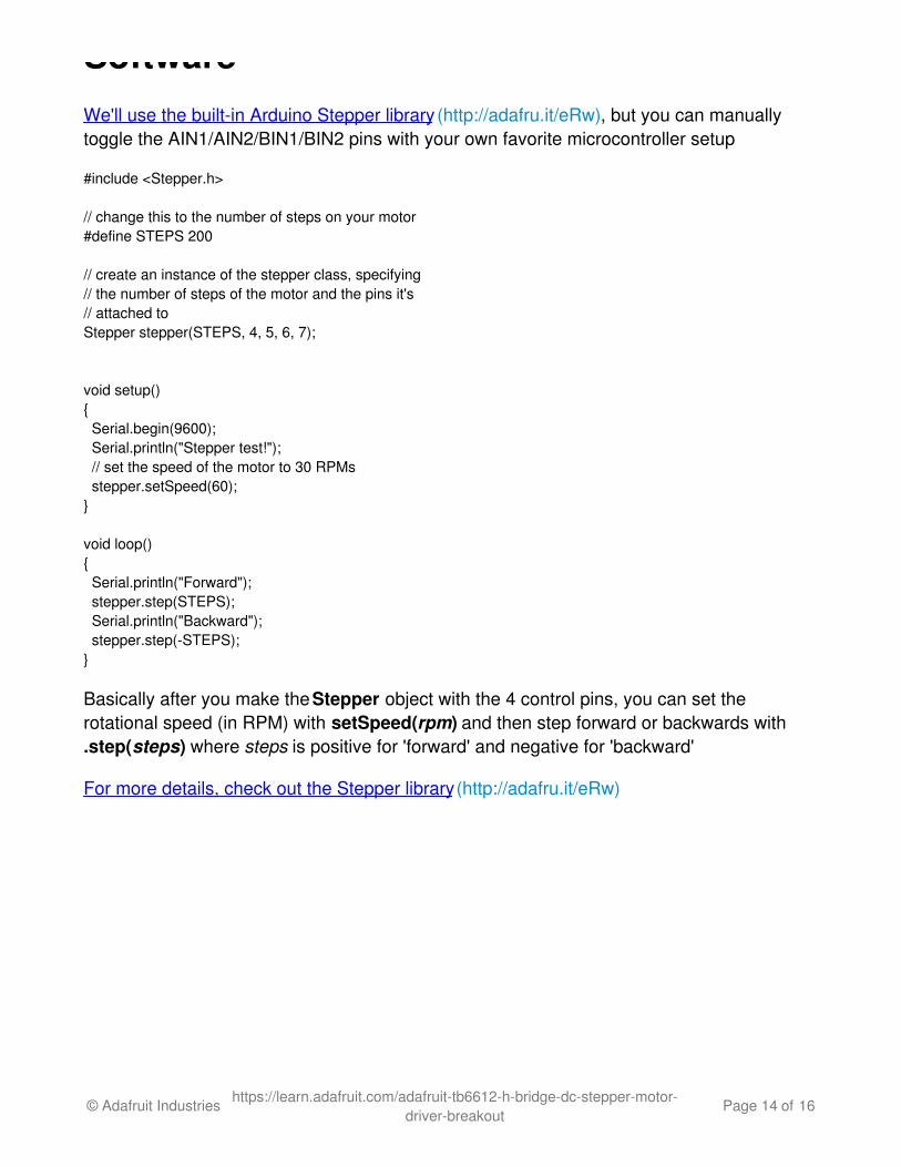
SoftwareWe'll use the built-in Arduino Stepper library (http://adafru.it/eRw), but you can manuallytoggle the AIN1/AIN2/BIN1/BIN2 pins with your own favorite microcontroller setup
#include <Stepper.h>
// change this to the number of steps on your motor#define STEPS 200
// create an instance of the stepper class, specifying// the number of steps of the motor and the pins it's// attached toStepper stepper(STEPS, 4, 5, 6, 7);
void setup(){ Serial.begin(9600); Serial.println("Stepper test!"); // set the speed of the motor to 30 RPMs stepper.setSpeed(60);}
void loop(){ Serial.println("Forward"); stepper.step(STEPS); Serial.println("Backward"); stepper.step(-STEPS);}
Basically after you make the Stepper object with the 4 control pins, you can set therotational speed (in RPM) with setSpeed(rpm) and then step forward or backwards with.step(steps) where steps is positive for 'forward' and negative for 'backward'
For more details, check out the Stepper library (http://adafru.it/eRw)
© Adafruit Industries https://learn.adafruit.com/adafruit-tb6612-h-bridge-dc-stepper-motor-driver-breakout
Page 14 of 16

Downloads
FilesThis motor driver is a fairly simple breakout of the TB6612 motor chip, so do check outthe datasheet for the TB6612 for any details you need about pin voltage limits,capacitance, etc! (http://adafru.it/emK)Fritzing object in the Adafruit Fritzing Library (http://adafru.it/aP3)EagleCAD PCB files (http://adafru.it/rF1)
Schematic
Fabrication print
© Adafruit Industries https://learn.adafruit.com/adafruit-tb6612-h-bridge-dc-stepper-motor-driver-breakout
Page 15 of 16

Dimensions in inches
© Adafruit Industries Last Updated: 2016-10-01 06:35:32 PM UTC Page 16 of 16


