Add a TFT Display to your AVR Micro Bruce E. Hall, W8BH Objective: control a 128x160 pixel TFT LCD module from your AVR microcontroller, using C. 1) INTRODUCTION I am a big fan of 2x16 character-based LCD displays. They are simple, cheap, and readily available. Send ASCII character data to them, and they display the characters. Nice. But sometimes characters are not enough. Colors, images, graphs, even text with fonts all require something more. The 1.8” TFT module from Adafruit (and others) gives you this option for the reasonable price of $25. Just buy one and have some fun learning what you can do with it. This TFT module is a 128x160 LCD matrix, controlled by the onboard Sitronix ST7735 controller. You send data to it serially using the Serial-Peripheral Interface (SPI) protocol. Simple, right? Unfortunately, it’s not as simple as writing to a character mode display. I started with two documents: the Siltronix datasheet and the Adafruit library. Take a look at both of them. For me, both are bit complicated. Even the initialization code looks like a programming nightmare. I like to start simple, and build as I go. Here is my approach. 2) MAKE THE CONNECTIONS Let’s connect the hardware first. The Adafruit module has 10 pins. On the bottom of the module each pin is labeled, from pin 1 ‘Lite’ to pin 10 ‘Gnd’. Mount the display module on a breadboard and connect the pins to your
Transcript
Add a TFT Display
to your AVR Micro
Bruce E. Hall, W8BH
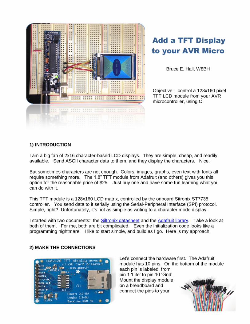
Objective: control a 128x160 pixel TFT LCD module from your AVR microcontroller, using C.
1) INTRODUCTION I am a big fan of 2x16 character-based LCD displays. They are simple, cheap, and readily available. Send ASCII character data to them, and they display the characters. Nice. But sometimes characters are not enough. Colors, images, graphs, even text with fonts all require something more. The 1.8” TFT module from Adafruit (and others) gives you this option for the reasonable price of $25. Just buy one and have some fun learning what you can do with it. This TFT module is a 128x160 LCD matrix, controlled by the onboard Sitronix ST7735 controller. You send data to it serially using the Serial-Peripheral Interface (SPI) protocol. Simple, right? Unfortunately, it’s not as simple as writing to a character mode display. I started with two documents: the Siltronix datasheet and the Adafruit library. Take a look at both of them. For me, both are bit complicated. Even the initialization code looks like a programming nightmare. I like to start simple, and build as I go. Here is my approach. 2) MAKE THE CONNECTIONS
Let’s connect the hardware first. The Adafruit module has 10 pins. On the bottom of the module each pin is labeled, from pin 1 ‘Lite’ to pin 10 ‘Gnd’. Mount the display module on a breadboard and connect the pins to your
AVR micro. Male to male prototyping wires are very handy for making these point-to-point connections. First, apply 5V power to the backlight, pin 1 and ground to pin 10. You should see the glow of the backlight when you do this. If not, check your power connections before proceeding further. Next, connect Vcc to 5V and the TFT select line to Gnd. Finally, hook up the four data lines: SCLK, MOSI, DC, and Reset. On Arduino-compatible boards, these connect to the digital 13, 11, 9, and 8 lines. On other AVR controllers, these lines may be labelled by their position on Port B: PB5, PB3, PB1, and PB0. 3) SERIAL PERIPHERAL INTERFACE (SPI)
Finding a good starting point is sometimes the hardest part! I chose the SPI protocol, since any data transfer to the TFT module would require this. There is a good overview of SPI using AVR micros at avrbeginners.net. The Arduino, and most AVR microcontrollers, have a fast, built-in hardware SPI interface which is easy to use. At its core, the SPI algorithm is very straightforward:
Put a data bit on the serial data line.
Pulse the clock line.
Repeat for all the bits you want to send, usually 8 bits at a time. You must set the microcontroller’s SPI control register (SPCR) to enable SPI communication. This is an eight-bit register that contains the following bits: SPCR = 0x50:
bit 7 bit 6 bit 5 bit 4 bit 3 bit 2 bit 1 bit 0
SPIE SPE DORD MSTR CPOL CPHA SPR1 SPR0
0 1 0 1 0 0 0 0
The first bit on the left, SPIE, enables the SPI interrupt and is not needed for this application. The SPE bit enables SPI. DORD determines the data direction: when 0, the most-significant bit is sent & received first. MSTR determines if the micro acts as a master (1) or slave (0) device. CPOL and CPHA together determine the transfer mode. Our TFT display works well with Mode 0, in which both bits are zero. Finally, SPR1 and SPR0 determine the transfer speed, as a fraction of the microcontroller’s oscillator. When both are 0, the SPI transfer speed is osc/4, which on my 16 MHz micro is 16/4 = 4 MHz. When both bits are 1, the transfer speed is osc/256 = 62.5 kHz.
Using an SPCR value of 0x50, SPI is enabled as Master, in Mode 0 at 4 MHz. The code to open SPI communication can be as simple as the following:
void OpenSPI()
{
SPCR = 0x50; // SPI enabled as Master, Mode0 at 4 MHz
}
To close SPI, just set the SPE bit to 0. This will stop SPI and return the four dedicated SPI lines (MOSI, MISO, SCLK, SS) to the general purpose I/O functions:
void CloseSPI()
{
SPCR = 0x00; // clear SPI enable bit
}
Only one more routine is needed: the SPI transfer routine. SPI is a bidirectional protocol, with two separate data lines. The data is transmitted over MOSI and received over MISO at the same time. Even if we only want to send, we are always going to receive. And vice versa. If you aren’t expecting any received data, just ignore what is returned to you. The data transfer register is SPDR. Load this register with a value, and the data transfer will start automatically. A bit in SPSR, the status register, will tell us when the transfer is complete. As the data bits are serially shifted out of the transfer register, the received bits are shifted in. When the transfer completes, SPDR will hold the received data:
byte Xfer(byte data) // you can use uint8_t for byte
{
SPDR = data; // initiate transfer
while (!(SPSR & 0x80)); // wait for transfer to complete
return SPDR;
}
The three routines above are all we need for SPI. Let’s make sure they work by doing a serial loop-back test. In this test, the output data on MOSI is looped-back as the input on MISO. Whatever value we put into the data register should come right back in. Without a working display, we need a way to verify the data. You might want to use your fancy debugger, or send the value to a monitor via UART, but here is something even simpler: flash the LED on your controller board. Most AVR boards have a connected LED. On many AVR boards, including the Arduino, the status LED is on PB5. Here is a routine to flash it:
void FlashLED(byte count)
// flash the on-board LED at ~ 2 Hz
{
DDRB |= _BV(DDB5); // Set PB5 as output
for (;count>0;count--)
{
PORTB |= _BV(PORTB5); // turn LED on
_delay_ms(250); // wait
PORTB &= ~_BV(PORTB5); // turn LED off
_delay_ms(250); // wait
}
}
Now, disconnect the microcontroller’s MOSI (digital 11, PB3) from the TFT display, and connect it to the microcontroller’s MISO line (digital 12, PB4). Run the following code:
int main()
{
OpenSPI(); // start communication to TFT
char i = Xfer(5); // MISO to MOSI -> returns 5
// MISO to +5V -> returns 255
// MISO to Gnd -> returns 0
CloseSPI(); // return portB lines to general use
FlashLED(i+1); // flash (returned value + 1)
}
What happens? If all goes well, the LED will flash 6 times. The value 5 is sent out the MOSI line, comes back in on the MISO line, and is returned from the SPI xfer routine. You may wonder if Xfer worked at all. Maybe nothing was transferred: the value 5 could have stayed in the transfer register ‘untouched’. How can we know for sure? For the doubters out there like me, take your wire on the MISO line and put to ground (logic 0). Now, all bits shifted-in will be 0, and the value returned should be 0x00000000 = 0. If you run the program now, the LED should flash only once. To further convince you, connect MISO to +5V. Now, all bits shifted-in will be one, and the value returned will always be 0x11111111 = 255. The LED should not flash at all, since 255+1 = 256 = 0, for byte-sized variables. 4) SENDING COMMANDS & DATA Serial information sent to the display module can be either commands or data. For commands, the D/C (data/command) input must be 0; for data, the input must be 1. We use a third microcontroller pin, D9/PB1, to supply this information. Here are the two routines:
#define ClearBit(x,y) x &= ~_BV(y) // equivalent to cbi(x,y)
#define SetBit(x,y) x |= _BV(y) // equivalent to sbi(x,y)
void WriteData (byte b)
{
Xfer(b); // assumes DC (PB1) is high
}
void WriteCmd (byte cmd)
{
ClearBit(PORTB,1); // 0=command, 1=data
Xfer(cmd);
SetBit(PORTB,1); // return DC high
}
I use two handy macros, ClearBit and SetBit, for clearing & setting individual bits. The WriteData routine just calls Xfer; it’s nice to have as an abstraction from the SPI layer, but… I don’t use it. We want to send data as fast as possible, and calling this routine instead of Xfer just adds time (and stack use). WriteCmd, on the other hand, makes sure that the Data/Command line is appropriately cleared before the command and set afterwards.
5) ST7735 TFT CONTROLLER The Sitronix ST7735 is a single-chip driver/controller for 128x160 pixel TFT-LCD displays. It can accept both serial and 8/9/16/18 bit parallel interfaces. On my module, and many others like it, only the serial interface over SPI is supported. The Sitronix datasheet refers to this interface as the “four-wire” SPI protocol. The ST7735 supports over 50 different commands. Many of these commands fine-tune the power output and color intensity settings, allowing you to correct for LCD display variations. In this tutorial we need only six of those commands. 6) INITIALIZING THE DISPLAY You should initialize the display before sending pixel data. I found a few code samples online, but they are a bit confusing. My favorite library, the Adafruit-ST7735-Library on GitHub, calls 19 different commands with over 60 parameters! Let’s find an easier solution. The first initialization step is to reset the controller, either by hardware or software. A hardware reset requires an additional GPIO line to pulse the controller’s reset pin. A software reset is a byte-sized command sent to the controller. I chose the hardware reset because of its reliability. The reset function initializes the controller registers to their default values. See the reset table in datasheet section 9.14.2 for more information. To do a hardware reset, take the reset line briefly low, and wait enough time for the reset to complete:
After the reset, the controller enters a low-power sleep mode. We wake the controller and turn on its TFT driver circuits with the sleep out SLPOUT command. Next, we set the controller to accept 16-bit pixel data. More on that below. Finally, after turning on the driver circuits, we need to enable display output with the DISPON (display on) command. Here is the code for our simplified initialization routine:
void InitDisplay()
{
HardwareReset(); // initialize display controller
WriteCmd(SLPOUT); // take display out of sleep mode
msDelay(150); // wait 150mS for TFT driver circuits
Now is a good time to check your hardware connections and run a program that calls InitDisplay(). Your display should briefly blank, and then show a screen full of tiny, random color pixels. If it does, you have successfully initialized the display. If not, check your hardware connections. It’s easy to get a couple I/O pins reversed, or forget a power/ground connection. Once you get it working, it’s time to send some real data.
7) DISPLAY COLOR MODES
The default color mode for this controller is RGB666. Pixel colors are a combination of red, green, and blue color values. Each subcolor has 6 bits (64 different levels) of intensity. Equal amounts of red, green, and blue light produce white. Equal amounts of blue and green produce cyan. Red and green make yellow. Since each color component is specified by 6 bits, the final color value is 18 bits in length. The number of possible color combinations in RGB666 colorspace is 2^18 = 262,144 or 256K. We represent these color combinations as an 18 bit binary number.
The 6 red bits are first, followed by 6 green bits, followed by 6 blue bits. Our controller wants to see data in byte-sized chucks, however. For every pixel we must send 24 bits (3 bytes), arranged as follows:
r r r r r r - - g g g g g g - - b b b b b b - -
The lowest two bits of each red, green, and blue byte are ignored; only the 6 upper bits of each byte are used. That’s a bit wasteful, isn’t it? It takes time to send those empty bits. The TFT controller supports three different color depths. Here they are:
COLOR MODE RGB SPACE Bits per Pixel Unique Colors
3 RGB444 12 16x16x16 = 4K
5 RGB565 16 32x64x32 = 64K
6 (default) RGB666 18 64x64x64 = 256K
Mode 6 is the default, requiring three bytes per pixel. Notice that Mode 5 is 16 bits in size, which is exactly 2 bytes in length. No waste! And it still provides for plenty of colors. If we use mode 5 instead of mode 6, each pixel can be sent in 2 bytes instead of 3. Data transmission will be faster, at the cost of less color depth. If 65,536 different colors are enough for you, this is a good tradeoff. Let’s use it. Here is how the red, green, and blue bits are packed into a 2-byte word:
r r r r r g g g g g g b b b b b
8) PIXELS Sending pixel data is as simple as sending both bytes of our 16-bit color, MSB first. We often want to send more than one pixel of the same color, so it can be helpful to add a counter loop:
void Write565 (int data, unsigned int count)
{
for (;count>0;count--)
{
WriteByte (data >> 8); // write hi byte
WriteByte (data & 0xFF); // write lo byte
}
}
To save CPU cycles, you may call Xfer directly, instead of WriteByte. Even faster, you can inline the Xfer code for each WriteByte call:
void Write565 (int data, unsigned int count)
// note: inlined spi xfer for optimization
{
for (;count>0;count--)
{
SPDR = (data >> 8); // write hi byte
while (!(SPSR & 0x80)); // wait for transfer to complete
SPDR = (data & 0xFF); // write lo byte
while (!(SPSR & 0x80)); // wait for transfer to complete
}
}
We must give screen coordinates before sending pixel data to the controller. The coordinates are not a single (x,y) location, but a rectangular region. To specify the region we need the controller commands CASET and RASET. The Column Address Set command sets the column boundaries, or x coordinates. The Row Address Set sets the row boundaries, or y coordinates. The two together set the display region where new data will be written.
We need to specify an active region, whether we’re filling a large rectangle or just a single pixel. First, specify the region; next, issue a RAMWR (memory write) command; and finally, send the raw pixel data. Notice how the following routines are similar:
void DrawPixel (byte x, byte y, int color)
{
SetAddrWindow(x,y,x,y); // set active region = 1 pixel
Write565(color,width*height); // set color data for all pixels
}
Both routines set the window, issue a memory write command, and then send the color data. For DrawPixel, the active window is a single pixel and only a single color value is sent. For FillRect, the active window is the entire rectangle, and the color value is sent width*height times. The RAMWR is always called before Write565, so from now on it will be issued from inside the Write565 routine.
9) LINES The simplest line to draw is a horizontal line along the x axis. For example, from x=3 to x=10. The length of this line is the difference, 10-3 = 7. Add one pixel so that the start-pixel and end-pixel are both included. The total length is 8 pixels.
2 3 4 5 6 7 8 9 10 11 To code it, set up a display window between the two positions on the x axis:
void HLine (byte x0, byte x1, byte y, int color)
{
byte width = x1-x0+1;
SetAddrWindow(x0,y,x1,y);
Write565(color,width);
}
Vertical lines are exactly the same, swapping the x and y axes.
void VLine (byte x, byte y0, byte y1, int color)
{
byte height = y1-y0+1;
SetAddrWindow(x,y0,x,y1);
Write565(color,height);
}
Other lines can be plotted by using the general linear equation y=mx+b. To use this method, iterate over each x from x0 to x1, calculate y, and draw the (x,y) pixel. The problem is that the slope of the line, m, is a floating-point number. Our 8-bit microcontroller cannot efficiently handles “floats”. A line-drawing method that uses integers will be much faster and take less code space. The integer-only line drawing algorithm was first described by Jack Bresenham in 1962. The source code contains a Line routine based on the Bresenham algorithm. 10) CIRCLES AND ELLIPSES The algebraic equation for a circle is x
2 + y
2 = r
2, where r is
the radius. It’s easiest to think of the center of circle at the (0,0) origin. For example, here is the graph of x
2 + y
2 = 4.
The radius, the distance from the origin, is 2. To create a filled circle, let’s do the right half of the circle first, starting from x=0 and ending with x=2. For each x value we will draw a vertical line from +y to –y, shown as a red line on the graph, where y is calculated from the circle equation:
This code creates the right half of the circle. The left half of the circle is a mirror image. All we need to add is a second vertical line at –x for each +x:
long r2 = radius * radius;
for (int x=0; x<=radius; x++)
{
byte y = intsqrt(r2-x*x);
VLine(x,y,-y,color);
VLine(-x,y,-y,color);
}
Finally, we must translate this circle from (0,0) to any arbitrary xPos,yPos position. Substitute (xPos+x) for x and (yPos+y) for y in the VLine calls. See the source code for the completed FillCircle routine. To create non-filled circles, use DrawPixel instead of VLine, drawing only the ‘ends’ of the line:
long r2 = radius * radius;
for (int x=0; x<=radius; x++)
{
byte y = intsqrt(r2-x*x);
DrawPixel(x,y,color); // VLine(x,y,-y,color)
DrawPixel(x,-y,color);
DrawPixel(-x,y,color); // VLine(-x,y,-y,color);
DrawPixel(-x,-y,color);
}
You can halve the number of square root calculations, exploiting the symmetry between the top and bottom halves of each quadrant. See the source code for the completed Circle() routine. Ellipses can be constructed in a similar way, using the formula x
2/ a
2 + y
2/ b
2 = 1. Instead, I
chose the mid-point circle algorithm. Obviously, you can use this algorithm for circles too!
11) TEXT
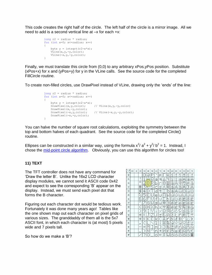
The TFT controller does not have any command for ‘Draw the letter B’. Unlike the 16x2 LCD character display modules, we cannot send it ASCII code 0x42 and expect to see the corresponding ‘B’ appear on the display. Instead, we must send each pixel dot that forms the B character. Figuring out each character dot would be tedious work. Fortunately it was done many years ago! Tables like the one shown map out each character on pixel grids of various sizes. The granddaddy of them all is the 5x7 ASCII font, in which each character is (at most) 5 pixels wide and 7 pixels tall. So how do we make a ‘B’?
Here is a 5x7 matrix for an uppercase B. Each matrix pixel will be represented by a bit. We can consider the whole character as a series of 35 individual bits. For simplicity, these bits are usually packaged in 8-bit bytes, with each row (or column) represented by 1 or more bytes. There are two basic formats for font data. Row major order means that the bits for the first row come first, then the second row, etc. Using Row major order, each 5x7 character is a 7 element list of row bytes, with 5 active bits in each byte and 3 bits unused. Each character requires 7 bytes.
The second format is Column major order. The bits of the first column are represented first, then the second column, etc. Using column-major order, a 5x7 character is a 5 element list of column bytes, with 7 active bits in each byte and 1 bit unused. Most representations of 5x7 characters use column major order, since it requires only 5 bytes to represent each character. Our B character is represented by 5 columns, left-most column first. Consider the third column, shown here horizontally, with the top pixel on the left:
1 0 0 1 0 0 1
There are 3 active pixels in blue. Substituting 1 for blue and 0 for white, the binary value is 0x1001001 or hexadecimal 0x49. The entire character is represented by an array of the five columns, or {0x7F, 0x49, 0x49, 0x49, 0x36}. I created a array of 96 characters from the standard 5x7 ASCII character set above and saved them in FONT_CHAR[96][5]. This array contains 96*5 = 480 bytes of information, which would use up much of the available data memory. For this reason, I stored it in program memory instead, using routines from <pgmspace.h> to access the data. 12) DRAW A CHARACTER
Here is the pseudocode for drawing a character:
Set the display window to a 5x7 pixel region
For each row & column bit, o If it’s a 0, set the pixel color to the background color o If it’s a 1, set the pixel color to the foreground color o Write the pixel to the display
That is fairly straightforward. Here is the code:
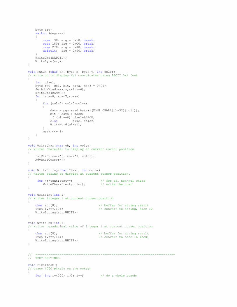
void PutCh (char ch, byte x, byte y, int color)
// write ch to display X,Y coordinates using ASCII 5x7 font
The font data is stored as an array of 96 characters. Since the characters are stored in ASCII order, starting with the space character (ASCII 32), the index to each character in the list is: ord(ch)-32. The character information returned into data is a byte containing the 7 pixels in the current column. In my font table, the columns are encoded with the least significant bit at the top, so we must lay down row pixel data starting with bit0, then row data for bit1, etc. This can be accomplished by creating a mask byte with bit0 initially set (mask = 0x01), then moving the bit leftward for each successive row (mask <<= 1). Other tables may put the msb at the top instead. In such tables you would start with a mask on bit 7 (mask = 0x80) and move the bit rightward for each successive row (mask >>= 1). 13) PORTRAIT MODE
Finally, it is time to fill our screen with text! How many characters will fit on the display? The default layout is portrait, with the display connectors along the top of the module. The display width is 128 pixels. Each character is 5 pixels wide. Allowing for one pixel space between characters, we can fit 128/6 = 21 characters per row. The display height is 160 pixels. Each character is 7 pixels tall. Allowing for one pixel space between rows, we can fit 160/8 = 20 rows of characters. The total number of characters per screen is therefore 21 chars/row x 20 rows = 420 characters. Here is a routine to display 420 characters on the screen:
void PortraitChars()
{
for (int i=420;i>0;i--)
{
byte x= i % 21;
byte y= i / 21;
char ascii = (i % 96)+32;
PutCh(ascii,x*6,y*8,CYAN);
}
}
14) LANDSCAPE MODE
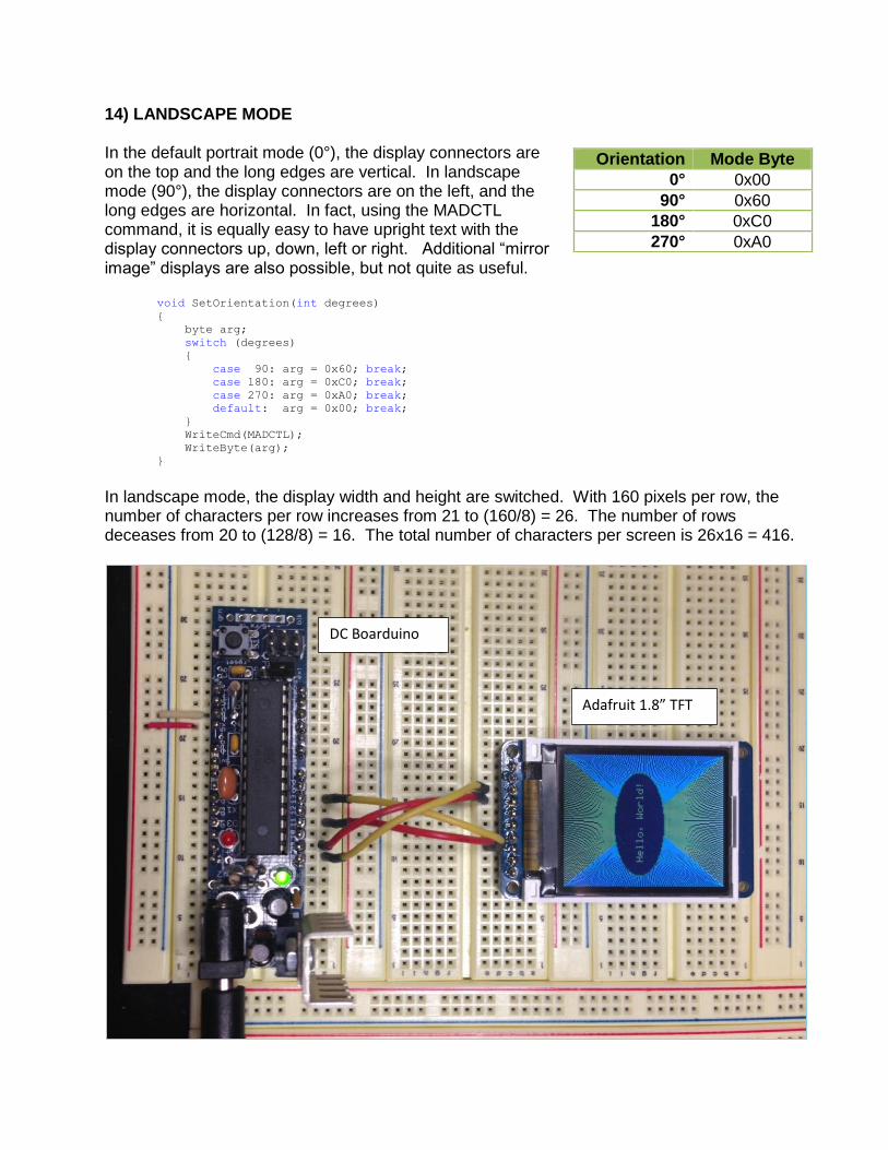
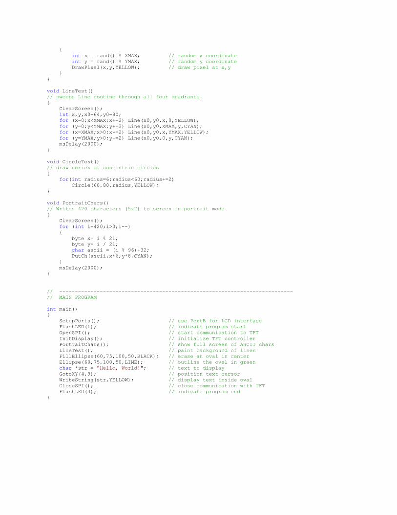
In the default portrait mode (0°), the display connectors are on the top and the long edges are vertical. In landscape mode (90°), the display connectors are on the left, and the long edges are horizontal. In fact, using the MADCTL command, it is equally easy to have upright text with the display connectors up, down, left or right. Additional “mirror image” displays are also possible, but not quite as useful.
void SetOrientation(int degrees)
{
byte arg;
switch (degrees)
{
case 90: arg = 0x60; break;
case 180: arg = 0xC0; break;
case 270: arg = 0xA0; break;
default: arg = 0x00; break;
}
WriteCmd(MADCTL);
WriteByte(arg);
}
In landscape mode, the display width and height are switched. With 160 pixels per row, the number of characters per row increases from 21 to (160/8) = 26. The number of rows deceases from 20 to (128/8) = 16. The total number of characters per screen is 26x16 = 416.
Orientation Mode Byte
0° 0x00
90° 0x60
180° 0xC0
270° 0xA0
DC Boarduino
Adafruit 1.8” TFT
15) MORE FUN In the source code I include a small demo that runs some of the text and graphic routines. Would you like to do more with this display, like use a wider variety of colors, create larger fonts, adjust the display gamma, or display bitmap files? Check out the series of articles I wrote for the raspberry pi. 16) SOURCE CODE //-----------------------------------------------------------------------------
// TFT: Experiments interfacing ATmega328 to an ST7735 1.8" LCD TFT display


![AVR - dl.melec.irdl.melec.ir/download/pdf/AVR/CodeVision-Fusebit[Melec.ir].pdf · AVR AVR AVR AVR 01 CodeVision CKSEL3..0 Device Clocking Option CKSEL3..0 External Crystal/Ceramic](https://static.documents.pub/doc/80x56/5cf6e10d88c99387248bfc0e/avr-dlmelecirdlmelecirdownloadpdfavrcodevision-fusebitmelecirpdf.jpg)


