Addendum #3 - Page 1 City of North Bend Simpson Park Improvements, Project #15.32.1 May 2018 ADDENDUM #3 - MAY 31, 2018 RE: CITY OF NORTH BEND North Bend Simpson Park Improvements Project #15.32.1 FROM: HGE INC., Architects, Engineers & Planners 333 South 4 th Street Coos Bay, Oregon 97420 541-269-1166 TO: Prospective Bidders This Addendum forms a part of the Contract Documents and modifies the original Documents dated May 2018, as noted below. Acknowledge receipt of this Addendum in the space provided on the Bid Form. Failure to do so may subject Bidder to disqualification. This Addendum consists of THREE (3) pages together with the following attachments: • Section 03-1000 - Concrete Forming and Accessories, Addendum #3 • Section 03-3000 - Cast-in-Place Concrete, Addendum #3 • Drawing Sheet G0.1 - Cover Sheet, Add #3 • Drawing Sheet C2.00 - Overall Site Plan, Add #3 • Drawing Sheet C3.00 - Civil Utility, Add #3 • Drawing Sheet C3.10 - Civil Utility, Add #3 • Drawing Sheet C3.20 - Signage, Add #3 • Drawing Sheet VA5.2 - Details • Drawing Sheet VA5.4 - Details • Drawing Sheet PA2.1 - Floor Plan, Add #3 • Drawing Sheet PA2.2, Add #3 • Drawing Sheet PA5.1, Add #3 • Drawing Sheet PA5.2 - Details CHANGES TO PROJECT MANUAL 1. Section 03-1000 - Concrete Forming and Accessories: REPLACE with attached Specification Section 03-1000 - Concrete Forming and Accessories, Revised, Addendum #3. 2. Section 03-3000 - Cast-in-Place Concrete: REPLACE with attached Specification Section 03-3000 - Cast-in-Place Concrete, Revised, Addendum #3. CHANGES TO DRAWINGS 1. Sheet G0.1, Cover Sheet: Replace with attached Sheet G0.1 Cover Sheet, ADD #3; updated Index.
Transcript
Addendum #3 - Page 1
City of North Bend Simpson Park Improvements, Project #15.32.1 May 2018
ADDENDUM #3 - MAY 31, 2018 RE: CITY OF NORTH BEND North Bend Simpson Park Improvements Project #15.32.1 FROM: HGE INC., Architects, Engineers & Planners
333 South 4th Street Coos Bay, Oregon 97420 541-269-1166
TO: Prospective Bidders This Addendum forms a part of the Contract Documents and modifies the original Documents dated May 2018, as noted below. Acknowledge receipt of this Addendum in the space provided on the Bid Form. Failure to do so may subject Bidder to disqualification. This Addendum consists of THREE (3) pages together with the following attachments:
City of North Bend Simpson Park Improvements, Project #15.32.1 May 2018
2. Sheet C2.00, Overall Site Plan: Replace with attached revised Sheet C2.00, Add #3, Overall Site Plan, for changes at drive area east of Visitor Information Center building, to accommodate two-way traffic, AND, changes to all Accessible Crossings, per recent changes in ODOT requirements (lengthening ramp landing areas).
following paragraph: “Project specific installation requirements and screw attachment procedure for roof CLT panels are as follows:
Install Main roof CLT panels starting at the lowest elevation panel and work towards the higher end. At the first panel, attach screws from CLT to ridge per 1/VS6.2 then push down the elevated corner, warping the panel and install screws per 11/VS6.1 to the exterior sill plate. The force required to warp the panel will be at least 300 lbs. Install the next panel adjacent to the first panel, attach to ridge beam in similar fashion, then connect the first and second CLT panels together per 9/VS6.2, only the diagonal screws from the first panel to the second panel. Next, attach the second CLT panel to the exterior wall per 11/VS6.1. Finally, connect the diagonal screws from the second panel to the first panel per 9/VS6.2.”
10. Sheet VS2.3, Structural Roof Framing Plan: Change overhang at Grid 7 to match Sheet VA2.1 - Floor Plan (1’-4”).
11. Sheet PA2.1, Floor Plan, and Sheet PA2.2: Replace with attached Sheets PA2.1-Add #3 and PA2.2-Add #3: Window sizes and type clarified.
Rockfon Sonar, Item #16201, Size 2x4, Narrow Tegular, Color - White, NRC - .95, Class A fire rating; Rockfon LLC, Telephone: 503-387-5773 / 800-323-7164.
Suspension System 09-5100 - Acoustical Ceilings, paragraph 2.02
Rockfon/Chicago Metallic Tempra 4000, Size 9/16, Heavy Duty, Color - White, Material - Steel; Rockfon LLC, Telephone: 503-387-5773 / 800-323-7164.
END OF ADDENDUM #3
03-1000 - Page 1
North Bend Simpson Park Improvements, Project # 15.32.1 May 2018 - REVISED Addendum #3
SECTION 03-1000CONCRETE FORMING AND ACCESSORIES
PART 1 GENERAL1.01 SECTION INCLUDES
A. Formwork for cast-in place concrete, with shoring, bracing and anchorage.B. Formliner - Textured Architectural Concrete.C. Openings for other work.D. Form accessories.E. Form stripping.
1.02 RELATED REQUIREMENTSA. Section 03-2000 - Concrete Reinforcing.B. Section 03-3000 - Cast-in-Place Concrete.C. Section 31-2316 - Excavation: Shoring and underpinning for excavation.
1.03 REFERENCE STANDARDSA. ACI 117 - Standard Specifications for Tolerances for Concrete Construction and Materials;
2010.B. ACI 301 - Specifications for Structural Concrete; 2010 (Errata 2012).C. ACI 318 - Building Code Requirements for Structural Concrete and Commentary; 2011.D. ACI 347R - Guide to Formwork for Concrete; 2014.
1.04 SUBMITTALSA. See Section 01-3000 - Administrative Requirements, for submittal procedures.B. Formliner Product Data: Provide data on void form materials and installation requirements.
1. Sample Panel: Submit a 24” x 24” sample of the formliner pattern for review and approval.2. Shop Drawings: Plan, elevation, and details showing overall pattern, joint locations, form
tie locations, end locations and other special conditions.3. Samples: Form ties, samples, and description, showing method of break-back when forms
are removed.PART 2 PRODUCTS2.01 FORMWORK - GENERAL
A. Provide concrete forms, accessories, shoring, and bracing as required to accomplishcast-in-place concrete work.
B. Design and construct to provide resultant concrete that conforms to design with respect toshape, lines, and dimensions.
C. Comply with applicable state and local codes with respect to design, fabrication, erection, andremoval of formwork.
D. Comply with relevant portions of ACI 347, ACI 301, and ACI 318.2.02 WOOD FORM MATERIALS
A. Form Materials: At the discretion of the Contractor.2.03 REMOVABLE PREFABRICATED FORMS
A. Manufacturers:1. Fitzgerald Formliners.2. SpecFormliner.3. Substitutions: See Section 01-6000 - Product Requirements.
B. Preformed Plastic Forms: Thermoplastic form liner, tight fitting, stiffened to support weight ofconcrete without deflection detrimental to tolerances and appearance of finished surfaces.
CONCRETE FORMING AND ACCESSORIES03-1000 - Page 2
North Bend Simpson Park Improvements, Project # 15.32.1 May 2018 - REVISED Addendum #3
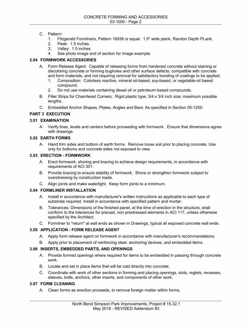
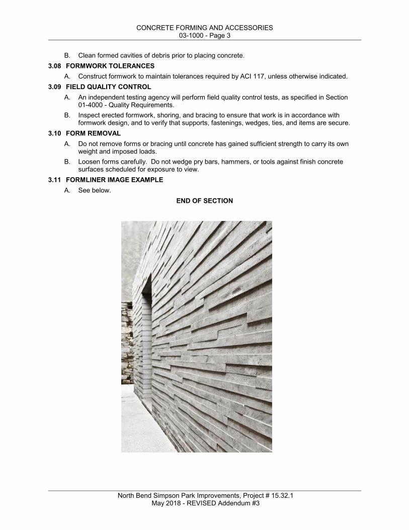
C. Pattern:1. Fitzgerald Formliners, Pattern 16938 or equal. 1.5" wide plank, Randon Depth PLank.2. Peak: 1.5 inches.3. Valley: 1.5 inches.4. See photo image end of section for image example.
2.04 FORMWORK ACCESSORIESA. Form Release Agent: Capable of releasing forms from hardened concrete without staining or
discoloring concrete or forming bugholes and other surface defects, compatible with concreteand form materials, and not requiring removal for satisfactory bonding of coatings to be applied.1. Composition: Colorless reactive, mineral oil-based, soy-based, or vegetable-oil based
compound.2. Do not use materials containing diesel oil or petroleum-based compounds.
B. Filler Strips for Chamfered Corners: Rigid plastic type; 3/4 x 3/4 inch size; maximum possiblelengths.
C. Embedded Anchor Shapes, Plates, Angles and Bars: As specified in Section 05-1200.PART 3 EXECUTION3.01 EXAMINATION
A. Verify lines, levels and centers before proceeding with formwork. Ensure that dimensions agreewith drawings.
3.02 EARTH FORMSA. Hand trim sides and bottom of earth forms. Remove loose soil prior to placing concrete. Use
only for bottoms and concrete sides not exposed to view.3.03 ERECTION - FORMWORK
A. Erect formwork, shoring and bracing to achieve design requirements, in accordance withrequirements of ACI 301.
B. Provide bracing to ensure stability of formwork. Shore or strengthen formwork subject tooverstressing by construction loads.
C. Align joints and make watertight. Keep form joints to a minimum.3.04 FORMLINER INSTALLATION
A. Install in accordance with manufacturer's written instructions as applicable to each type ofsubstrate required. Install in accordance with specified pattern and mortar.
B. Tolerances: Dimensions of the finished panel, at the time of erection in the structure, shallconform to the tolerances for precast, non prestressed elements in ACI 117, unless otherwisespecified by the Architect.
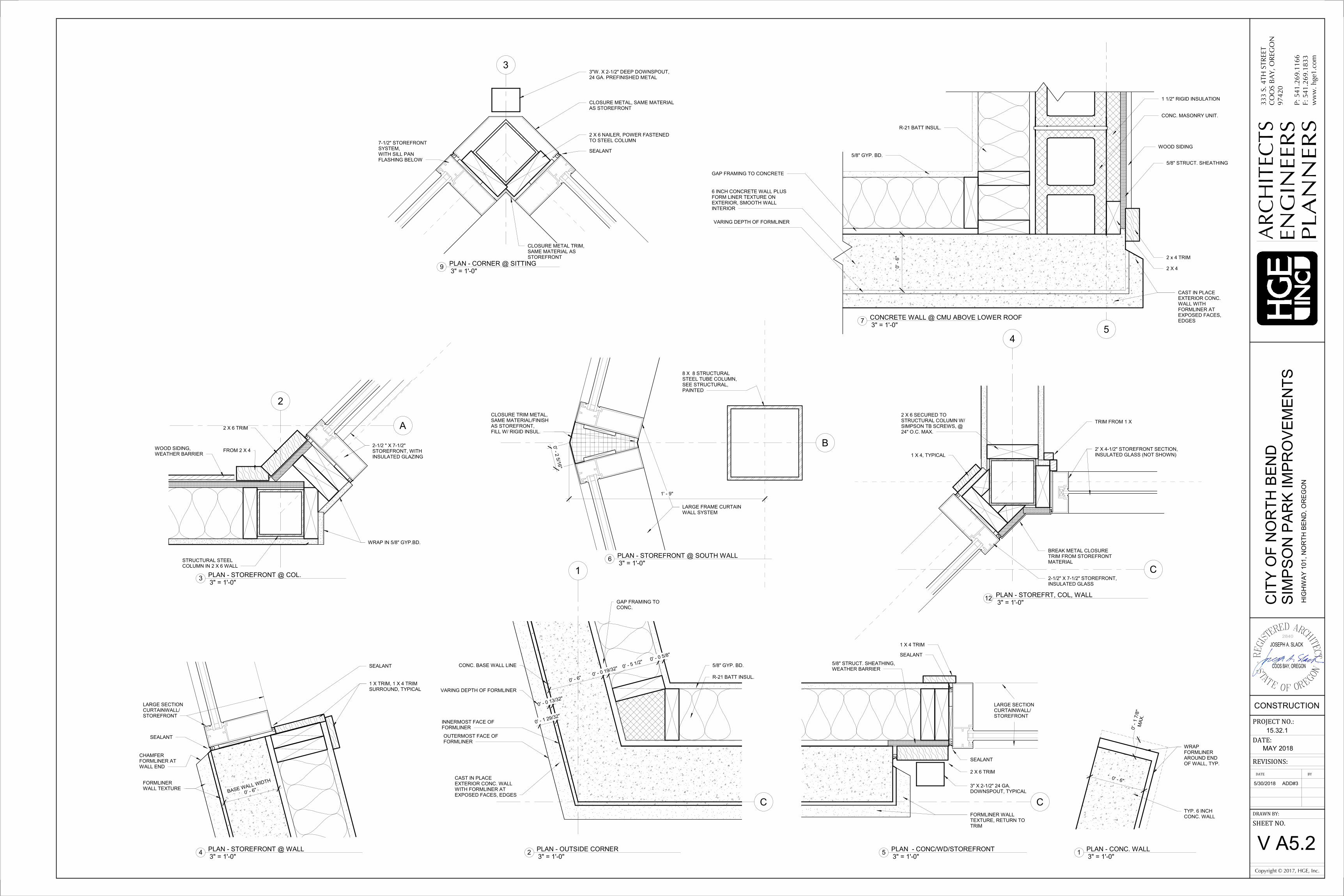
C. Formliner to "return" at wall ends as shown in Drawings, typical all exposed concrete wall ends.3.05 APPLICATION - FORM RELEASE AGENT
A. Apply form release agent on formwork in accordance with manufacturer's recommendations.B. Apply prior to placement of reinforcing steel, anchoring devices, and embedded items.
3.06 INSERTS, EMBEDDED PARTS, AND OPENINGSA. Provide formed openings where required for items to be embedded in passing through concrete
work.B. Locate and set in place items that will be cast directly into concrete.C. Coordinate with work of other sections in forming and placing openings, slots, reglets, recesses,
sleeves, bolts, anchors, other inserts, and components of other work.3.07 FORM CLEANING
A. Clean forms as erection proceeds, to remove foreign matter within forms.
CONCRETE FORMING AND ACCESSORIES03-1000 - Page 3
North Bend Simpson Park Improvements, Project # 15.32.1 May 2018 - REVISED Addendum #3
B. Clean formed cavities of debris prior to placing concrete.3.08 FORMWORK TOLERANCES
A. Construct formwork to maintain tolerances required by ACI 117, unless otherwise indicated.3.09 FIELD QUALITY CONTROL
A. An independent testing agency will perform field quality control tests, as specified in Section01-4000 - Quality Requirements.
B. Inspect erected formwork, shoring, and bracing to ensure that work is in accordance withformwork design, and to verify that supports, fastenings, wedges, ties, and items are secure.
3.10 FORM REMOVALA. Do not remove forms or bracing until concrete has gained sufficient strength to carry its own
weight and imposed loads.B. Loosen forms carefully. Do not wedge pry bars, hammers, or tools against finish concrete
surfaces scheduled for exposure to view.3.11 FORMLINER IMAGE EXAMPLE
A. See below.END OF SECTION
CONCRETE FORMING AND ACCESSORIES03-1000 - Page 4
North Bend Simpson Park Improvements, Project # 15.32.1 May 2018 - REVISED Addendum #3
03-3000 - Page 1
North Bend Simpson Park Improvements, Project # 15.32.1 May 2018 - REVISED Addendum #3
SECTION 03-3000CAST-IN-PLACE CONCRETE
PART 1 GENERAL1.01 SECTION INCLUDES
A. Floors and slabs on grade.B. Concrete foundation walls and exposed exterior walls with formliner texture, exposed smooth
interior walls.C. Joint devices associated with concrete work.D. Miscellaneous concrete elements, including equipment pads, light pole bases, thrust blocks,
and manholes.1.02 RELATED REQUIREMENTS
A. Section 014000 - Quality Requirements.B. Section 03-1000 - Concrete Forming and Accessories: Forms and accessories for formwork.C. Section 03-2000 - Concrete Reinforcing.D. Section 03-3511 - Concrete Floor Finishes: Densifiers, hardeners, applied coatings, and
polishing.1.03 REFERENCE STANDARDS
A. ACI 117 - Standard Specifications for Tolerances for Concrete Construction and Materials;2010.
B. ACI 211.1 - Standard Practice for Selecting Proportions for Normal, Heavyweight, and MassConcrete; 1991 (Reapproved 2009).
C. ACI 301 - Specifications for Structural Concrete; 2010 (Errata 2012).D. ACI 302.1R - Guide for Concrete Floor and Slab Construction; 2004 (Errata 2007).E. ACI 304R - Guide for Measuring, Mixing, Transporting, and Placing Concrete; 2000.F. ACI 306R - Cold Weather Concreting; 2010.G. ACI 318 - Building Code Requirements for Structural Concrete and Commentary; 2014.H. ACI 347R - Guide to Formwork for Concrete; 2014.I. ASTM C33/C33M - Standard Specification for Concrete Aggregates; 2013.J. ASTM C39/C39M - Standard Test Method for Compressive Strength of Cylindrical Concrete
Specimens; 2015a.K. ASTM C94/C94M - Standard Specification for Ready-Mixed Concrete; 2015.L. ASTM C109/C109M - Standard Test Method for Compressive Strength of Hydraulic Cement
Mortars (Using 2-in. or (50-mm) Cube Specimens); 2013.M. ASTM C150/C150M - Standard Specification for Portland Cement; 2015.N. ASTM C171 - Standard Specification for Sheet Materials for Curing Concrete; 2007.O. ASTM C173/C173M - Standard Test Method for Air Content of Freshly Mixed Concrete by the
Volumetric Method; 2014.P. ASTM C260/C260M - Standard Specification for Air-Entraining Admixtures for Concrete; 2010a.Q. ASTM C494/C494M - Standard Specification for Chemical Admixtures for Concrete; 2013.R. ASTM C618 - Standard Specification for Coal Fly Ash and Raw or Calcined Natural Pozzolan
for Use in Concrete; 2015.S. ASTM C1059/C1059M - Standard Specification for Latex Agents for Bonding Fresh to
Hardened Concrete; 2013.T. ASTM C1107/C1107M - Standard Specification for Packaged Dry, Hydraulic-Cement Grout
(Nonshrink); 2014.
CAST-IN-PLACE CONCRETE03-3000 - Page 2
North Bend Simpson Park Improvements, Project # 15.32.1 May 2018 - REVISED Addendum #3
U. ASTM C1240 - Standard Specification for Silica Fume Used in Cementitious Mixtures; 2014.1.04 SUBMITTALS
A. See Section 01-3000 - Administrative Requirements, for submittal procedures.B. Product Data: Submit manufacturers' data on manufactured products showing compliance with
1. Indicate proposed mix design complies with requirements of ACI 301, Section 4 - ConcreteMixtures.
2. Indicate proposed mix design complies with requirements of ACI 318, Chapter 5 -Concrete Quality, Mixing and Placing.
D. Sustainable Design Submittal: If any fly ash, ground granulated blast furnace slag, silica fume,rice hull ash, or other waste material is used in mix designs to replace Portland cement, submitthe total volume of concrete cast in place, mix design(s) used showing the quantity of portlandcement replaced, reports showing successful cylinder testing, and temperature on day of pour ifcold weather mix is used.
E. Project Record Documents: Accurately record actual locations of embedded utilities andcomponents that will be concealed from view upon completion of concrete work.
F. Warranty: Submit manufacturer warranty and ensure forms have been completed in Owner'sname and registered with manufacturer.
1.05 QUALITY ASSURANCEA. Perform work of this section in accordance with ACI 301 and ACI 318.B. Follow recommendations of ACI 306R when concreting during cold weather.
1.06 WARRANTYA. See Section 01-7800 - Closeout Submittals, for additional warranty requirements.B. Slabs with Moisture Vapor Reducing Admixture (MVRA): Provide warranty to cover the cost of
flooring failures due to moisture migration from slabs for ten years.1. Include cost of repair or removal of failed flooring, placement of topical moisture
remediation system, and replacement of flooring with comparable flooring system.PART 2 PRODUCTS2.01 FORMWORK
A. Comply with requirements of Section 03-1000.B. Formwork Design and Construction: Comply with guidelines of ACI 347R to provide formwork
that will produce concrete complying with tolerances of ACI 117.2.02 REINFORCEMENT
A. Comply with requirements of Section 03-2000.2.03 CONCRETE MATERIALS
A. Cement: ASTM C150/C150M, Type I - Normal Portland type.1. Acquire all cement for entire project from same source.
B. Fine and Coarse Aggregates: ASTM C 33.1. Acquire all aggregates for entire project from same source.
C. Fly Ash: ASTM C618, Class C or F.D. Calcined Pozzolan: ASTM C618, Class N.E. Silica Fume: ASTM C1240, proportioned in accordance with ACI 211.1.F. Water: Clean and not detrimental to concrete.
CAST-IN-PLACE CONCRETE03-3000 - Page 3
North Bend Simpson Park Improvements, Project # 15.32.1 May 2018 - REVISED Addendum #3
2.04 ADMIXTURESA. Do not use chemicals that will result in soluble chloride ions in excess of 0.1 percent by weight
of cement.B. Air Entrainment Admixture: ASTM C260/C260M.
polyethylene or equivalent, complying with ASTM E1745, Class A; stated by manufacturer assuitable for installation in contact with soil or granular fill under concrete slabs. The use ofsingle ply polyethylene is prohibited.1. Installation: Comply with ASTM E1643.2. Accessory Products: Vapor retarder manufacturer's recommended tape, adhesive,
mastic, prefabricated boots, etc., for sealing seams and penetrations.3. Manufacturers:
a. Stego Industries, LLC: www.stegoindustries.com.b. Substitutions: See Section 01-6000 - Product Requirements.
B. Non-Shrink Cementitious Grout: Premixed compound consisting of non-metallic aggregate,cement, water reducing and plasticizing agents.1. Grout: Comply with ASTM C1107/C1107M.2. Minimum Compressive Strength at 28 Days, ASTM C109/C109M: 7,000 pounds per
a. Hilti RE-500 V3.b. Simpson SET-XP or 3.c. Or equivalent.
2.06 BONDING AND JOINTING PRODUCTSA. Latex Bonding Agent: Non-redispersable acrylic latex, complying with ASTM C1059/C1059M,
Type II.1. Manufacturers:
a. SpecChem, LLC; Strong Bond Acrylic Bonder: www.specchemllc.com/sle.b. W.R. Meadows, Inc.; ACRY-LOK-: www.wrmeadows.com/sle.c. Substitutions: See Section 01-6000 - Product Requirements.
B. Slab Isolation Joint Filler: 1/2 inch thick, height equal to slab thickness, with removable topsection that will form 1/2 inch deep sealant pocket after removal.1. Material: ASTM D1751, cellulose fiber.
2.07 CURING MATERIALSA. Evaporation Reducer: Liquid thin-film-forming compound that reduces rapid moisture loss
caused by high temperature, low humidity, and high winds; intended for application immediatelyafter concrete placement.1. Manufacturers:
a. SpecChem, LLC; SpecFilm Concentrate or SpecFilm RTU:www.specchemllc.com/#sle.
b. W. R. Meadows, Inc; Evapre or Evapre-RTU: www.wrmeadows.com/#sle.c. Substitutions: See Section 01-6000 - Product Requirements.
B. Moisture-Retaining Sheet: ASTM C171.1. Curing paper, regular.
2.08 CONCRETE MIX DESIGNA. Proportioning Normal Weight Concrete: Comply with ACI 211.1 recommendations.
CAST-IN-PLACE CONCRETE03-3000 - Page 4
North Bend Simpson Park Improvements, Project # 15.32.1 May 2018 - REVISED Addendum #3
1. Replace as much Portland cement as possible with fly ash, ground granulated blastfurnace slag, silica fume, or rice hull ash as is consistent with ACI recommendations.
B. Admixtures: Add acceptable admixtures as recommended in ACI 211.1 and at ratesrecommended or required by manufacturer.
C. Normal Weight Concrete:1. Compressive Strength, when tested in accordance with ASTM C 39/C 39M at 28 days:
4,000 psi, unless drawings indicate otherwise. Concrete should be a minimum of a 6-sackmix.
2. Fly Ash Content: Maximum 15 percent of cementitious materials by weight.3. Calcined Pozzolan Content: Maximum 10 percent of cementitious materials by weight.4. Silica Fume Content: Maximum 5 percent of cementitious materials by weight.5. Water-Cement Ratio: Maximum 40 percent by weight.6. Total Air Content: 4-1/2 percent, determined in accordance with ASTM C173/C173M, 5%
for concrete exposed to soil/weather.7. Maximum Slump: 4 inches.8. Maximum Aggregate Size: 3/4 inch.
2.09 MIXINGA. Transit Mixers: Comply with ASTM C94/C94M.
PART 3 EXECUTION3.01 EXAMINATION
A. Verify lines, levels, and dimensions before proceeding with work of this section.3.02 PREPARATION
A. Formwork: Comply with requirements of ACI 301. Design and fabricate forms to support allapplied loads until concrete is cured, and for easy removal without damage to concrete.
B. Where new concrete is to be bonded to previously placed concrete, prepare existing surface bycleaning with steel brush and applying bonding agent in accordance with manufacturer'sinstructions.1. Use latex bonding agent only for non-load-bearing applications.
3.03 REBAR DOWELING WITH EPOXY ADHESIVEA. Install in accordance with manufacturers evaluation report.
3.04 PLACING CONCRETEA. Place concrete in accordance with ACI 304R.B. Place concrete for floor slabs in accordance with ACI 302.1R.C. Notify Architect and Owner's Independant Testing Agency not less than 24 hours prior to
commencement of placement operations.D. Ensure reinforcement, inserts, embedded parts, and formed construction joint devices will not
be disturbed during concrete placement.E. Place concrete continuously without construction (cold) joints wherever possible; where
construction joints are necessary, before next placement prepare joint surface by removinglaitance and exposing the sand and sound surface mortar, by sandblasting or high-pressurewater jetting.
F. Finish floors level and flat, unless otherwise indicated, within the tolerances specified below.3.05 SLAB JOINTING
A. Locate joints as indicated on the drawings.
CAST-IN-PLACE CONCRETE03-3000 - Page 5
North Bend Simpson Park Improvements, Project # 15.32.1 May 2018 - REVISED Addendum #3
B. Anchor joint fillers and devices to prevent movement during concrete placement.C. Isolation Joints: Use preformed joint filler with removable top section for joint sealant, total
height equal to thickness of slab, set flush with top of slab.3.06 FLOOR FLATNESS AND LEVELNESS TOLERANCES
A. Maximum Variation of Surface Flatness:1. Exposed Concrete Floors: 1/4 inch in 10 feet.
B. Correct the slab surface if tolerances are less than specified.C. Correct defects by grinding or by removal and replacement of the defective work. Areas
requiring corrective work will be identified. Re-measure corrected areas by the same process.3.07 CONCRETE FINISHING
A. Repair surface defects, including tie holes, immediately after removing formwork.B. Unexposed Form Finish: Rub down or chip off fins or other raised areas 1/4 inch or more in
height.C. Exposed Form Finish: Rub down or chip off and smooth fins or other raised areas 1/8 inch or
more in height. Provide finish as follows:1. Smooth Rubbed Finish: Wet concrete and rub with carborundum brick or other abrasive,
not more than 24 hours after form removal.D. Vertical Cast-In-Place Concrete:
1. Avoid patching.2. Fill tie holes with approved and appropriate tie-hole patching compounds only, expansive
or non-shrink, matching color of concrete. Compound to be shrinkage compensating toremain tightly in the tie hole,.
E. Concrete Slabs: Finish to requirements of ACI 302.1R, and as follows:1. Surfaces to Receive Thin Floor Coverings: "Steel trowel" as described in ACI 302.1R; thin
floor coverings include carpeting, resilient flooring, seamless flooring, resinous matrixterrazzo, thin set quarry tile, and thin set ceramic tile.
2. Decorative Exposed Surfaces: Trowel as described in ACI 302.1R; use steel-reinforcedplastic trowel blades instead of steel blades to avoid black-burnish marks; decorativeexposed surfaces include surfaces to be stained or dyed, pigmented concrete, surfaces toreceive liquid hardeners, surfaces to receive dry-shake hardeners, surfaces to be polished,and all other exposed slab surfaces.
3. Other Surfaces to Be Left Exposed: Trowel as described in ACI 302.1R, minimizingburnish marks and other appearance defects.
4. Sidewalk Paving, ramps: Light broom, texture perpendicular to direction of travel withtroweled and radiused edge 1/4 inch radius.
3.08 CURING AND PROTECTIONA. Comply with requirements of ACI 308R. Immediately after placement, protect concrete from
premature drying, excessively hot or cold temperatures, and mechanical injury.B. Maintain concrete with minimal moisture loss at relatively constant temperature for period
necessary for hydration of cement and hardening of concrete.C. Formed Surfaces: Cure by moist curing with forms in place for full curing period.D. Surfaces Not in Contact with Forms:
1. Initial Curing: Start as soon as free water has disappeared and before surface is dry.Keep continuously moist for not less than three days by water ponding, water-saturatedsand, water-fog spray, or saturated burlap.
2. Final Curing: Begin after initial curing but before surface is dry.a. Moisture-Retaining Sheet: Lap strips not less than 3 inches and seal with waterproof
tape or adhesive; secure at edges.
CAST-IN-PLACE CONCRETE03-3000 - Page 6
North Bend Simpson Park Improvements, Project # 15.32.1 May 2018 - REVISED Addendum #3
3.09 FIELD QUALITY CONTROLA. An independent testing agency will perform field quality control tests, as specified in Section
01-4000 - Quality Requirements.B. Provide free access to concrete operations at project site and cooperate with appointed firm.C. Submit proposed mix design of each class of concrete to inspection and testing firm for review
prior to commencement of concrete operations.D. Tests of concrete and concrete materials may be performed at any time to ensure conformance
with specified requirements.E. Compressive Strength Tests: ASTM C39/C39M. For each test, mold and cure three concrete
test cylinders. Obtain test samples for every 100 cubic yards or less of each class of concreteplaced.
F. Take one additional test cylinder during cold weather concreting, cured on job site under sameconditions as concrete it represents.
3.10 DEFECTIVE CONCRETEA. Test Results: The testing agency shall report test results in writing to Architect and Contractor
within 24 hours of test.B. Defective Concrete: Concrete not conforming to required lines, details, dimensions, tolerances
or specified requirements.C. Repair or replacement of defective concrete will be determined by the Architect. The cost of
additional testing shall be borne by Contractor when defective concrete is identified.D. Do not patch, fill, touch-up, repair, or replace exposed concrete except upon express direction
of Architect for each individual area.3.11 PROTECTION
A. Do not permit traffic over unprotected concrete floor surface until fully cured.B. Protect slabs scheduled for exposed finish, polished or trowel finish, from damage, staining, or
discoloration during entire course of construction.END OF SECTION
138
I-5
101
4297
20
38
101
395
20
84
30
395
30
I-5
84
OWNERCITY OF NORTH BENDHIGHWAY 101NORTH BEND, OR 97459CONTACT:TERRENCE O'CONNORCITY MANAGER
ARCHITECTHGE, Inc.ARCHITECTS, ENGINEERS& PLANNERS333 S. 4TH STREETCOOS BAY, OREGON 97420PHONE: 541.269.1166 FAX: 541.269.1833CONTACT - JOSEPH A. SLACK, AIAPROJECT ARCHITECT -OFFICE: 541-269-1166 EXT 273
STRUCTURAL ENGINEERDCI ENGINEERS921 SW WASHINGTON STREETSUITE 560PORTLAND, OR 97205PHONE: 503.242.2448CONTACT: KYLE KRAXBERGER, PE
ALUMINUMABOVE FINISHED FLOORARCHITECTBALLED AND BURLAPPEDBOTTOM OF CURBBENCHMARKBUILDINGBOTTOM OF SLOPEBEGINNING OF VERTICALCURVEBOTH WAYSCALIPERCATCH BASINCAST IRONCIRCULARCENTERLINECLEANOUTCONCRETECONTINUOUSCONTRACTORCORNERCROSS SLOPECUBIC FEETCUBIC YARDDEGREE OF CURVATUREDROP MANHOLEDRINKING FOUNTAINDIMENSIONDIAMETERDOUBLEDEMOLISH / DEMOLITIONEACHELEVATION
LENGTH OF CURVELATITUDELOW POINTLEFTLINEARLINEAR FEETLANDSCAPE CONTRACTORLANDSCAPE ARCHITECTMETERMAXIMUMMANHOLEMANUFACTURERMINIMUMMISCELLANEOUSMONUMENTNOT IN CONTRACTNOT TO SCALENUMBERNOMINAL DIMENSIONON CENTEROUTSIDE DIAMETEROWNER FURNISHED,CONTRACTOR INSTALLEDOWNER FURNISHED,OWNER INSTALLEDPLANTING AREAPOLYVINYL CHLORIDE PIPEPOINT OF CURVATUREPOINT OF COMPOUNDCURVATUREPROPERTY LINEPOINT OF TANGENTPLYWOOD
PANELPOUNDS PER SQUARE INCHPRESSURE TREATEDRADIUSRIGHT OF WAYRIGHTREQUIREDREVISIONREINFORCINGSANITARYSECTIONSHEET VINYLSIMILARSTORM DRAINSTORM INLETSANITARY SEWERSPECIFICATIONS OR SPECIFIEDSQUARESQUARE FOOTSQUARE YARDSTATIONSTAINLESS STEELTANGENTTOP OF CURBTAPERED ENDTONGUE & GROOVETOP OF WALLTOP OF SLOPETOWNSHIPTYPICALUNLESS NOTED OTHERWISEU.S. GEOLOGICAL SURVEYVERTICAL CURVE


![Addendum and Late Reports Agendahonourroll.tweed.nsw.gov.au/Controls/Meetings/...INFORMATION TECHNOLOGY . 21. 51 . ADDENDUM [FRIT-CM] Monthly Investment Report for Period ending 31](https://static.documents.pub/doc/80x56/600f73a4ed8f4f223841219b/addendum-and-late-reports-information-technology-21-51-addendum-frit-cm.jpg)


