ibm.com/redbooks Front cover Advanced Networking Concepts Applied Using Linux on IBM System z Lydia Parziale Ben Louie Eric Marins Tiago Nunes dos Santos Srivatsan Venkatesan Understand the IBM z/VM failover concepts Build a practical network solution using Linux on System z Configure routers and switches for redundancy
Transcript
ibm.com/redbooks
Front cover
Advanced Networking Concepts Applied Using Linux on IBM System z
Lydia ParzialeBen Louie
Eric MarinsTiago Nunes dos Santos
Srivatsan Venkatesan
Understand the IBM z/VMfailover concepts
Build a practical network solution using Linux on System z
vi Advanced Networking Concepts Applied Using Linux on IBM System z
Notices
This information was developed for products and services offered in the U.S.A.
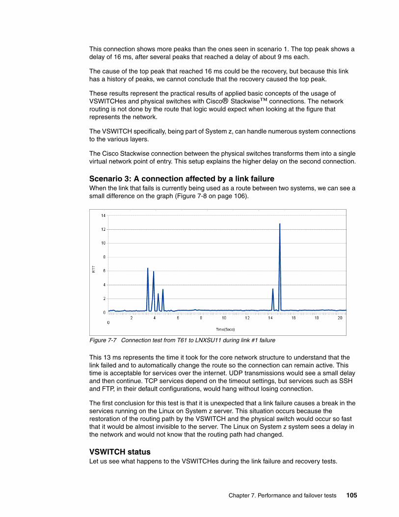
IBM may not offer the products, services, or features discussed in this document in other countries. Consult your local IBM representative for information on the products and services currently available in your area. Any reference to an IBM product, program, or service is not intended to state or imply that only that IBM product, program, or service may be used. Any functionally equivalent product, program, or service that does not infringe any IBM intellectual property right may be used instead. However, it is the user's responsibility to evaluate and verify the operation of any non-IBM product, program, or service.
IBM may have patents or pending patent applications covering subject matter described in this document. The furnishing of this document does not give you any license to these patents. You can send license inquiries, in writing, to: IBM Director of Licensing, IBM Corporation, North Castle Drive, Armonk, NY 10504-1785 U.S.A.
The following paragraph does not apply to the United Kingdom or any other country where such provisions are inconsistent with local law: INTERNATIONAL BUSINESS MACHINES CORPORATION PROVIDES THIS PUBLICATION "AS IS" WITHOUT WARRANTY OF ANY KIND, EITHER EXPRESS OR IMPLIED, INCLUDING, BUT NOT LIMITED TO, THE IMPLIED WARRANTIES OF NON-INFRINGEMENT, MERCHANTABILITY OR FITNESS FOR A PARTICULAR PURPOSE. Some states do not allow disclaimer of express or implied warranties in certain transactions, therefore, this statement may not apply to you.
This information could include technical inaccuracies or typographical errors. Changes are periodically made to the information herein; these changes will be incorporated in new editions of the publication. IBM may make improvements and/or changes in the product(s) and/or the program(s) described in this publication at any time without notice.
Any references in this information to non-IBM websites are provided for convenience only and do not in any manner serve as an endorsement of those websites. The materials at those websites are not part of the materials for this IBM product and use of those websites is at your own risk.
IBM may use or distribute any of the information you supply in any way it believes appropriate without incurring any obligation to you.
Information concerning non-IBM products was obtained from the suppliers of those products, their published announcements or other publicly available sources. IBM has not tested those products and cannot confirm the accuracy of performance, compatibility or any other claims related to non-IBM products. Questions on the capabilities of non-IBM products should be addressed to the suppliers of those products.
This information contains examples of data and reports used in daily business operations. To illustrate them as completely as possible, the examples include the names of individuals, companies, brands, and products. All of these names are fictitious and any similarity to the names and addresses used by an actual business enterprise is entirely coincidental.
COPYRIGHT LICENSE:
This information contains sample application programs in source language, which illustrate programming techniques on various operating platforms. You may copy, modify, and distribute these sample programs in any form without payment to IBM, for the purposes of developing, using, marketing or distributing application programs conforming to the application programming interface for the operating platform for which the sample programs are written. These examples have not been thoroughly tested under all conditions. IBM, therefore, cannot guarantee or imply reliability, serviceability, or function of these programs.
IBM, the IBM logo, and ibm.com are trademarks or registered trademarks of International Business Machines Corporation in the United States, other countries, or both. These and other IBM trademarked terms are marked on their first occurrence in this information with the appropriate symbol (® or ™), indicating US registered or common law trademarks owned by IBM at the time this information was published. Such trademarks may also be registered or common law trademarks in other countries. A current list of IBM trademarks is available on the Web at http://www.ibm.com/legal/copytrade.shtml
The following terms are trademarks of the International Business Machines Corporation in the United States, other countries, or both:
Global Technology Services®HiperSockets™IBM®Redbooks®
Redbooks (logo) ®System z10®System z®Tivoli®
WebSphere®z/OS®z/VM®z10™
The following terms are trademarks of other companies:
Windows, and the Windows logo are trademarks of Microsoft Corporation in the United States, other countries, or both.
Intel, Intel logo, Intel Inside, Intel Inside logo, Intel Centrino, Intel Centrino logo, Celeron, Intel Xeon, Intel SpeedStep, Itanium, and Pentium are trademarks or registered trademarks of Intel Corporation or its subsidiaries in the United States and other countries.
Linux is a trademark of Linus Torvalds in the United States, other countries, or both.
Other company, product, or service names may be trademarks or service marks of others.
viii Advanced Networking Concepts Applied Using Linux on IBM System z
This IBM® Redbooks® publication describes important networking concepts and industry standards that are used to support high availability on IBM System z®. Some of the networking standards described here are VLANs, VLAN trunking, link aggregation, virtual switches, VNICs, and load-balancing.
We examine the various aspects of network setups and introduce the main Linux on System z networking commands and configuration files. We describe the management of network interface parameters, assignment of addresses to a network interface, and usage of the ifconfig command to configure network interfaces.
We provide an overview of connectivity options available on the System z platform. We also describe high availability concepts and building a high availability solution using IBM Tivoli® System Automation. We also provide the implementation steps necessary to build a redundant network connections set up between an IBM z/VM® system and the external network switches using two Open Systems Adapter-Express 3 (OSA-Express 3) adapters with 10 Gb Ethernet ports.
We describe the tests performed in our lab environment. The objectives of these tests were to gather information about performance and failover from the perspective of a real scenario, where the concepts of described in this book were applied.
The environment we worked with had the following hardware and software components:
� Red Hat Enterprise Linux 5.6 and 6.1� SUSE Linux Enterprise Server 11 SP1� IBM System z10®� IBM J48I switch
This book is focused on information that is practical and useful for readers with experience in network analysis and engineering networks, System z and Linux systems administrators, especially for readers that administer networks in their day-to-day activities.
The team who wrote this book
This book was produced by a team of specialists from around the world working at the International Technical Support Organization, Poughkeepsie Center.
Lydia Parziale is a Project Leader for the ITSO team in Poughkeepsie, New York, with national and international experience in technology management, including software development, project leadership, and strategic planning. Her areas of expertise include e-business development and database management technologies. Lydia is a certified PMP and an IBM Certified IT Specialist with an MBA in Technology Management and has been employed by IBM for over 20 years in various technology areas.
Ben Louie is a Senior IT Architect and IBM Certified Professional working in Integrated Communications Services within IBM Global Technology Services® in IBM Canada. He joined IBM in 1994 after graduating with a degree in Computer Engineering from the University of Waterloo, Canada. He is a Cisco Certified Internet Expert (CCIE) and has worked as a technical team leader on many network infrastructure design and implementation projects for external clients in financial and public service sectors.
Eric Marins is an IT Specialist for IBM Global Technology and Services in Brazil. He has eight years of experience in configuring Linux on System z. He is currently working as a Team Lead for the Linux team in Brazil and also as a Linux Specialist supporting more than 1800 Linux on System z servers for an IBM internal account. He holds a degree in Computer Science from Faculdade Ruy Barbosa and a post-graduate degree in Computer Information Systems (Database Management). His areas of expertise include Linux, high availability, IP networking, and server management.
Tiago Nunes dos Santos is a Software Engineer at the IBM Brazil Linux Technology Center. He has five years of experience in server management and computer networks. His areas of expertise include Linux for a large audience, computer networking, and support area leadership.
Srivatsan Venkatesan is an IT Specialist at the IBM Systems and Technology Group in Poughkeepsie, NY. He has one year of experience in the z/VM and Linux on System z field. He holds a degree in Computer Science from the University of South Carolina. His areas of expertise include Linux and middleware applications on System z.
Thanks to the following people for their contributions to this project:
David Bennin, Roy P Costa, Robert HaimowitzInternational Technical Support Organization, Poughkeepsie Center
Bill Bitner and Sandy BulsonIBM US
Ricardo Coelho de SousaIBM Brazil
Now you can become a published author, too!
Here’s an opportunity to spotlight your skills, grow your career, and become a published author—all at the same time! Join an ITSO residency project and help write a book in your area of expertise, while honing your experience using leading-edge technologies. Your efforts will help to increase product acceptance and customer satisfaction, as you expand your network of technical contacts and relationships. Residencies run from two to six weeks in length, and you can participate either in person or as a remote resident working from your home base.
Find out more about the residency program, browse the residency index, and apply online at:
ibm.com/redbooks/residencies.html
Comments welcome
Your comments are important to us!
We want our books to be as helpful as possible. Send us your comments about this book or other IBM Redbooks publications in one of the following ways:
� Use the online Contact us review Redbooks form found at:
ibm.com/redbooks
x Advanced Networking Concepts Applied Using Linux on IBM System z
xii Advanced Networking Concepts Applied Using Linux on IBM System z
Chapter 1. Networking concepts overview
This chapter covers the networking concepts and industry standards that are being used to support high availability on System z. It is assumed that you have some networking background to fully understand the concepts described in this chapter.
A virtual local area network (VLAN) is defined in a switch that sets the boundary of a broadcast domain for hosts to communicate with each other. A VLAN has the same attributes as a physical local area network (LAN) and it can be extended between different switches within or across different sites.
Today, VLANs are created in the switch to mimic the Ethernet segmentation services that are traditionally provided by the routers in LAN configurations. Figure 1-1 gives a conceptual view of a VLAN.
Figure 1-1 The VLAN concept
A logical VLAN interface can be created in a Layer 3 switch so that it can route traffic between VLANs.
LAN #1
LAN #2
LAN #3
LA N #1
LA N #2
LAN #3
2 Advanced Networking Concepts Applied Using Linux on IBM System z
1.2 VLAN trunking
VLAN trunking allows multiple VLANs to coexist on a single network connection. Frames from individual VLANs must be identified when they are going through a single interface. VLAN tagging is the most common and preferred method. It inserts a VLAN ID into a frame header to identify which VLAN the frame belongs to. A frame exists at Layer 2 of the Open System Interconnection (OSI) model, and a packet exists at Layer 3 of this model.
A switchport can be configured in either access or trunk mode. The access mode can only support single VLAN traffic. In trunk mode, the switchport forwards and receives tagged frames; thus, it can support multiple VLANs. Because a trunk is typically a point-to-point connection between two switches, it should be run in full-duplex mode.
The two most common VLAN tagging methods are Cisco’s proprietary Inter-Switch Link (ISL) and the IEEE 802.1Q specification. ISL is an older standard that Cisco was using to connect its switches and routers. IEEE 802.1Q is the new networking standard that supports VLANs on an Ethernet network. It is the only option available for use in an environment that uses multiple-vendor equipment.
We focus on the IEEE 802.1Q trunking protocol, because ISL is similar to IEEE 802.1Q and the only practical difference is that ISL tags every VLAN frame in a trunk interface while IEEE 802.1Q does not tag the native VLAN frame.
1.2.1 IEEE 802.1Q protocol
IEEE 802.1Q adds a 32-bit field, called a VLAN tag, between the source Media Access Control (MAC) address and the Ether Type or Length field of an Ethernet frame. The VLAN frame tag format can be seen in Figure 1-2. The VLAN tag is labeled as 802.1Q TAG and is circled in this figure.
As shown in Figure 1-3, this inserted field includes a 4 byte tag header containing a 2 byte (represented here as 16 bits) tag protocol identifier (TPID) and 2 byte tag control information (TCI). The TPID has a fixed value of 0x8100 that indicates the frame carries the 802.1Q/802.1p TAG information. The TCI contains the following elements:
� Three-bit user priority: The priority code point (PCP) indicates the frame priority level.
� One-bit canonical format indicator (CFI): If the value of this field is 1, the MAC address is in non-canonical format. If the value is 0, the MAC address is in canonical format. It is always set to zero for Ethernet switches.
� Twelve-bit VLAN identifier (VID) that uniquely identifies the VLAN to which the frame belongs.
Figure 1-3 VLAN tag fields
1.2.2 Native VLAN
ISL is designed for a trunking connection between two switches that must work with the trunking protocol. IEEE 802.1Q is designed to support trunking over the Ethernet where there might be devices that do not understand VLAN tagging. Thus, IEEE 802.1Q includes the feature of Native VLAN where its frames are not tagged.
In Cisco products, when a switchport is configured in Trunk mode using IEEE 802.1Q encapsulation, if you do not specify the Native VLAN, the default is VLAN1. In Juniper products, the Native VLAN must be explicitly defined.
A best practice would be to keep Native VLAN identical on both devices that form a trunk link; otherwise, the trunk link does not operate properly and it might create a looping effect that could destabilize the network.
1.3 Link aggregation
Link aggregation is a computer networking term that describes the various methods of bundling multiple network connections in parallel to increase bandwidth throughput and provide redundancy. The combination of multiple physical Ethernet ports to form a virtual logical link is called a link aggregation group (LAG). Cisco called it EtherChannel while Juniper called it Aggregated Ethernet.
TPIDTCI
PCP CFI VID
16 bit 3 bit 1 bit 12 bit
4 Advanced Networking Concepts Applied Using Linux on IBM System z
Link aggregation is shown in Figure 1-4.
Figure 1-4 Link aggregation
Link aggregation is similar to NIC teaming or bonding. The difference is that link aggregation involves support and cooperation on the physical switch.
In the past, a limitation of the link aggregation protocol was that all physical ports in the aggregation group had to be on a single switch. Newer technologies, such as Juniper Virtual Chassis Technology, Cisco StackWise Technology, Virtual Switching System (VSS), and Nexus virtual PortChannels (vPC), remove this limitation by allowing the physical ports to be split between two or more switches in a triangle configuration (Figure 1-5). The benefit of the virtualized switch setup allows the system to eliminate a single point of failure and failover with subsecond recovery time.
Figure 1-5 Link aggregation triangle
Switch1 Switch2
Eth0
Eth1
Eth3
Eth2
Eth0
Eth1
Eth3
Eth2
Mu
lti-
Lin
k
Ch
ann
el
Switch1 Switch2
Eth0
Eth1
Eth3
Eth2
Eth0
Eth1
Eth3
Eth2Multi-link Channel
Switch1 Switch2
Eth0 Eth0
Server
Multi-Link Channel
Virtual-Link Connection
Eth1 Eth2
Chapter 1. Networking concepts overview 5
There are two methods in a LAG configuration:
� Using a negotiation protocol� Static
The common protocols used are Port Aggregation Protocol (PAgP) and Link Aggregation Control Protocol (LACP).
PAgP is Cisco’s proprietary networking protocol for channel negotiation between two Cisco switches or between a Cisco switch and a server that supports PAgP (some server / NIC manufacturers license this feature from Cisco). Link Aggregation Control Protocol (LACP), also known as IEEE 802.3ad, is an open standard that is supported by most networking vendors. Because LACP covers all the functionality of PAgP, the only reason to use PAgP would be for compatibility with earlier version purposes. According to the Cisco:
“LACP is the recommended solution for configuration of port channel interfaces to the Nexus 7000, as NX-OS does not currently support PAgP.”1
Link Aggregation Control Protocol (LACP) is a vendor agnostic standard that provides a method to control the bundling of several physical ports together to form a single logical channel. LACP is a negotiation protocol that allows a network device to establish a multilink channel by sending Link Aggregation Control Protocol Data Unit (LACPDU) packets to the peer device. Both devices must be running LACP and are directly connected.
The following requirements must be met before a multilink channel can be formed:
� Same speed / duplex on each port.� Access VLAN (if not trunked).� Same trunking type (VLAN and native VLAN (if trunked) are allowed.)� Each port must have the same STP cost per VLAN within the multilink channel.� No SPAN or monitoring ports.
A typical Cisco switch supports three modes of EtherChannel:
� LACP: Channel-group x mode active� PAgP: Channel-group x mode desirable� Static: Channel-group x mode on
Other vendors, such as Juniper Networks, support LACP and static mode.
Unless the network is managed by highly qualified professionals and governed by strict change management control processes, we should avoid the use of static configured LAG. The use of LACP / PAgP helps in detecting and mitigating configuration errors and the impact of using them is justified. Static mode should only be used as a last resort when there is no other alternative.
1.4 Virtual switch
A virtual switch (VSWITCH) is a software program that enables one virtual host to communicate with another virtual host within a computer system. Virtual switches typically emulate functions of a physical Ethernet switch. In Linux on System z, a VSWITCH provides direct attachment of z/VM guests to the local physical network segment. The VSWITCH allows IP network architects and network administrators to treat z/VM guests as a server in the network.
Most z/VM virtualization involves abstracting and sharing real hardware among multiple guests. Virtual switches do not physically exist. VSWITCHs use real Open System Adapter (OSA) hardware to transmit data to and from the “outside” world, but that architecture is not apparent to the guests connecting to the VSWITCH.
A typical virtual switch emulates the functions of a Layer 2 switch and does not provide a routing function like a typical Cisco / Juniper Layer 3 switch. Most virtual switches, such as a z/VM virtual switch and Cisco Nexus 1000V, do offer link aggregation support with LACP to achieve high availability.
For more information about Guest LANs and VSWITCHs, see 2.2.1, “Guest LANs / HiperSockets” on page 17 and 2.2.2, “Virtual switches” on page 17.
1.5 Virtual network interface controller
A virtual network interface controller (VNIC) is a pseudo-network interface that is created within a system or a virtual server. The VNIC is assigned a MAC address that must be unique within the VLAN. A VNIC can be configured just like a normal NIC with an IP address, a subnet mask, and a default gateway.
1.6 Ethernet autonegotiation
Ethernet autonegotiation allows devices to automatically exchange, over a link, information about speed, duplex, and flow control abilities. Because the first version of IEEE 802.3u specification was open to different interpretations, products from manufacturers using different implementations had interoperability problems.
The newer IEEE Ethernet standards specifies that gigabit Ethernet over copper wiring requires autonegotiation. It eliminates the debatable portions of the autonegotiation specifications. Table 1-1 show some of these newer standards with autonegotiation.
Table 1-1 IEEE standards
A duplex mismatch occurs when two connected devices are configured in different duplex modes (one in half-duplex mode while the other is in full-duplex mode). The impact might not be as apparent in low traffic load; however, after the traffic load increases, the performance degrades dramatically to a point that is unacceptable for the users. The evidence of duplex mismatch can be confirmed by the high number of input errors, runts, cyclic redundancy checks (CRC), collisions, and late collisions in the output of a show interface command.
Ethernet Standard Date Description
802.3u 1995 100BASE-TX, 100BASE-T4, and 100BASE-FX Fast Ethernet at 100 Mbps (12.5 MBps) with autonegotiation
802.3ab 1999 1000BASE-T Gbps Ethernet over twisted pair at 1 Gbps (125 MBps)
802.3ae 2003 10 Gbps (1,250 MBps) Ethernet over fiber; 10GBASE-SR, 10GBASE-LR, 10GBASE-ER, 10GBASE-SW, 10GBASE-LW, and 10GBASE-EW
Chapter 1. Networking concepts overview 7
Example 1-1 shows an example of this command’s output in a Cisco environment.
Example 1-1 show interfaces command output in a Cisco environment
Cisco#sh int gigabitEthernet 1/1/3GigabitEthernet1/1/3 is up, line protocol is up (connected) Hardware is C6k 1000Mb 802.3, address is 588d.098a.4e12 (bia 588d.098a.4e12) Description: WAN Connection MTU 1500 bytes, BW 100000 Kbit, DLY 100 usec, reliability 255/255, txload 6/255, rxload 3/255 Encapsulation ARPA, loopback not set Keepalive set (10 sec) Full-duplex, 100Mb/s, media type is 10/100/1000BaseT input flow-control is off, output flow-control is on Clock mode is auto ARP type: ARPA, ARP Timeout 04:00:00 Last input 00:00:01, output 00:00:44, output hang never Last clearing of "show interface" counters 7w3d Input queue: 0/2000/3/0 (size/max/drops/flushes); Total output drops: 120 Queueing strategy: fifo Output queue: 0/40 (size/max) 5 minute input rate 1211000 bits/sec, 292 packets/sec 5 minute output rate 2494000 bits/sec, 324 packets/sec 601023372 packets input, 253315601491 bytes, 0 no buffer Received 1687181 broadcasts (1676243 multicasts) 0 runts, 0 giants, 0 throttles 0 input errors, 0 CRC, 0 frame, 3 overrun, 0 ignored 0 watchdog, 0 multicast, 0 pause input 0 input packets with dribble condition detected 561697781 packets output, 320584196200 bytes, 0 underruns 0 output errors, 0 collisions, 2 interface resets 0 babbles, 0 late collision, 0 deferred 0 lost carrier, 0 no carrier, 0 PAUSE output 0 output buffer failures, 0 output buffers swapped outCisco#
Example 1-2 shows an example of this command’s output in a Juniper environment.
Example 1-2 show interfaces command output in a Juniper environment
root> show interfaces xe-0/1/0 extensivePhysical interface: xe-0/1/0, Enabled, Physical link is Up Interface index: 230, SNMP ifIndex: 594, Generation: 233 Link-level type: Ethernet, MTU: 1514, Speed: 10Gbps, Duplex: Full-Duplex, BPDU Error: None, MAC-REWRITE Error: None, Loopback: Disabled, Source filtering: Disabled, Flow control: Disabled Device flags : Present Running Interface flags: SNMP-Traps Internal: 0x0 Link flags : None CoS queues : 8 supported, 8 maximum usable queues Hold-times : Up 0 ms, Down 0 ms Current address: 2c:6b:f5:3d:b4:00, Hardware address: 2c:6b:f5:39:a3:33 Last flapped : 2011-10-07 17:00:14 UTC (4d 01:16 ago) Statistics last cleared: Never Traffic statistics: Input bytes : 12752340788715 15952 bps
8 Advanced Networking Concepts Applied Using Linux on IBM System z
As a best practice, switchports for servers that are using FastEthernet should have autonegotiation disabled and switchports for servers that are using Gigabit Ethernet (both 1 and 10 Gbps) should have autonegotiation turned on.
1.7 Maximum transmission unit
Maximum transmission unit (MTU) refers to the size of the largest packet that a network protocol can transmit without fragmentation. A larger MTU brings greater efficiency because each packet carries more user data as compared to a packet with a smaller MTU while the IP headers remain fixed. The resulting higher efficiency improves throughput for bulk transfer protocols such as the file transfer protocol (FTP) and Internet Small Computer System Interface (iSCSI).
The standard Ethernet MTU is 1500 bytes and a typical jumbo frame MTU is 9000 bytes. At the time that the Ethernet standard was created, the 1,518-byte frame size was optimal for 10 Mbps Ethernet. For Gigabit Ethernet and 10 Gb Ethernet, a 1500 byte MTU size is the bottleneck in throughput performance.
There are several reasons to use 9000 bytes as the preferred size for jumbo frames:
� They are large enough to carry an 8 KB application datagram (such as the network file system or NFS) without fragmentation
� They do not exceed the Ethernet 32-Bit CRC limitation.
� The delay of using 9000 bytes MTU on a GigabitEthernet is less than the delay of using 1500 bytes MTU on a slower Ethernet.
As network components become more reliable and faster, jumbo frames improve overall system performance dramatically. The challenge is compatibility with earlier versions, as jumbo frames require that all devices in the network can process the jumbo frames. One approach is to enable the jumbo frame within a subnetwork domain, such as a data center, so that optimal performance can be achieved within that domain.
10 Advanced Networking Concepts Applied Using Linux on IBM System z
1.8 Spanning Tree Protocol
The Spanning Tree Protocol (STP), standardized as IEEE 802.1D, is a loop-prevention protocol. It is a technology that allows bridges (also known as switches) to communicate with each other to discover physical loops in the network. The protocol specifies an algorithm that bridges use to create a loop-free logical topology.
Rapid Spanning Tree Protocol (RSTP), known as standard IEEE 802.1w, provides faster spanning tree convergence after a topology change. RSTP introduces new convergence behaviors and bridge port roles and it is backwards-compatible with STP.
It takes STP 30 - 50 seconds to respond to a topology change. It takes RSTP no more than 6 seconds or within a few milliseconds of a physical link failure for spanning tree convergence.
Many vendors (for example, Cisco and Juniper) support STP and RSTP on their switches. The VSWITCH in z/VM does not participate in the Spanning Tree Protocol. The VSWITCH can be thought of as an edge switch and the only way to achieve connectivity redundancy is by using link aggregation.
1.9 Load balancing
Network traffic can be forwarded through multiple paths to achieve load balancing / load sharing and redundancy. One drawback of load sharing is that when a failure happens on one of the links, the remaining links might not have enough capacity to support the wanted throughput unless the design has provided for it. Thus, the network designer must ensure that sufficient bandwidth is available to meet user requirements during a worst case scenario.
Typical network load balancing / load sharing can be achieved by using Layer 2 or Layer 3 protocols.
1.9.1 Layer 2 load sharing
Link aggregation operates at the Layer 2 level, as it uses MAC addresses for packet delivery. Link aggregation provides fast recovery time (typically within the subsecond range). Layer 2 load balancing / load sharing can be used between two network switches or between a server and a network switch. One limitation of using Layer 2 load balancing over WAN circuits is that it requires all member links to have similar network connection types with a true Layer 2 LAN extension service. For example, it is impossible to bundle an Asynchronous Transfer Mode (ATM) based WAN link and a Dense Wavelength Division Multiplexing (DWDM) based WAN link.
The IEEE 802.3ad (LACP) specification did not explicitly define the load distribution algorithm for the network device to send traffic out of the LAG. It is up to the vendor to implement the load sharing algorithm based on their hardware platform.
Chapter 1. Networking concepts overview 11
Cisco - EtherChannelThis load-balancing method is based on Layer 2 / Layer 3 information (Table 1-2).
Table 1-2 Layer 2 / Layer 3 information
Network administrators can configure LAG to use any of these settings.
Juniper - Aggregated EthernetJuniper uses the following settings to send traffic out of the LAG:
� Uses src/dst addresses and src/dst ports for IP traffic whether they are switched or routed
� Uses only src/dst MAC addresses for non-IP Layer 2 traffic, such as BPDUs
Juniper switches do not provide a user configurable load balancing method with LAG.
1.9.2 Layer 3 load sharing
In certain situations where Layer 2 load sharing is not possible, such as using WAN links from different vendors, consider using a Layer 3 load sharing method. Layer 3 load sharing (Figure 1-6) uses a routing protocol, and the recovery time typically depends on the routing protocol’s convergence time.
Figure 1-6 Layer 3 load sharing
The most widely used Layer 3 interior routing protocols are Open Shortest Path First (OSPF) and Enhanced Interior Gateway Routing Protocol (EIGRP).
Setting Description
dst-ip Destination IP address
dst-mac Destination MAC address
src-dst-ip Source XOR destination IP address
src-dst-mac Source XOR destination MAC address
src-ip Source IP address
src-mac Source MAC address
WAN#2 LAN-X 1Gbps
Site BSite A
10.10.10.0/30 VLAN998
WAN#1 LAN-X 1Gbps
10.10.10.4/30 VLAN999S iS i
Switch A
SiS i
Switch B
.2 .3
.5 .6
12 Advanced Networking Concepts Applied Using Linux on IBM System z
Open Shortest Path FirstOSPF is an open standard link-state routing protocol. It only supports equal weight load sharing among each path. OSPF exchanges information with its neighbor using the Hello protocol. The name Hello is not an acronym, but refers to the word hello. The Hello protocol and the dead interval are the two timers that can be configured for fine-tuning.
The dead interval is the number of seconds that the router / switch should wait between receiving Hello packets from a neighbor before declaring that the adjacency to that neighbor is down. The dead interval must be longer than the Hello interval, or the OSPF neighbor is not established reliably.
By default, OSPF Hello packets are sent every 10 seconds on a broadcast type network, such as Ethernet, and on a point-to-point type network, such as frame-relay. The dead interval is four times the Hello interval (40 seconds by default). Thus, it takes up to 40 seconds, by default, for OSPF to detect a link failure.
The Hello interval can be set from 1 to 255 seconds on most vendor’s network routers and switches. All OSPF neighbors must have the same Hello interval configured to establish a neighbor relationship. Thus, the network designer can set the Hello interval to one second and the dead interval to 3 seconds to achieve a faster link failure detection.
Cisco has supported the OSPF Fast Hello packets feature since IOS version 12.2(15)T. This feature allows for 1 second OSPF link failure detection. The Hello packets are sent in an interval of less than one second, governed by the multiplier specified in the ip ospf dead-interval minimal hello-multiplier command (Example 1-3).
Example 1-3 Setting Fast Hello
Router# config tRouter(config)#interface e1/1Router(config)# ip ospf dead-interval minimal hello-multiplier 5Router(config)# endRouter#Router# show ip ospf interface ethernet 1/1Ethernet1/1 is up, line protocol is up Internet Address 10.10.10.2/24, Area 0 Process ID 1, Router ID 10.11.0.2, Network Type BROADCAST, Cost:1 Transmit Delay is 1 sec, State DR, Priority 1 Designated Router (ID) 10.11.10.2, Interface address 10.10.10.2 Backup Designated router (ID) 10.11.0.1, Interface address 10.10.10.1 Timer intervals configured, Hello 200 msec, Dead 1, Wait 1, Retransmit 5 Hello due in 80msecIndex 2/2, flood queue length 0 Next 0x0(0)/0x0(0) Last flood scan length is 2, maximum is 3 Last flood scan time is 0 msec, maximum is 0 msec Neighbor Count is 1, Adjacent neighbor count is 1 Adjacent with neighbor 10.11.0.1 (Backup Designated Router) Suppress hello for 0 neighbor(s)
OSPF Fast Hello should be applied on fast and reliable network links, as the Hello traffic that it creates might use up substantial bandwidth for a slower network link.
Enhanced Interior Gateway Routing Protocol EIGRP is a Cisco proprietary routing protocol that supports unequal weight load sharing among each path.
Chapter 1. Networking concepts overview 13
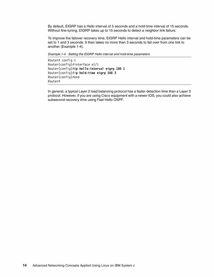
By default, EIGRP has a Hello interval of 5 seconds and a hold-time interval of 15 seconds. Without fine-tuning, EIGRP takes up to 15 seconds to detect a neighbor link failure.
To improve the failover recovery time, EIGRP Hello interval and hold-time parameters can be set to 1 and 3 seconds. It then takes no more than 3 seconds to fail over from one link to another (Example 1-4).
Example 1-4 Setting the EIGRP Hello interval and hold-time parameters
In general, a typical Layer 2 load balancing protocol has a faster detection time than a Layer 3 protocol. However, if you are using Cisco equipment with a newer IOS, you could also achieve subsecond recovery time using Fast Hello OSPF.
14 Advanced Networking Concepts Applied Using Linux on IBM System z
Chapter 2. Linux on System z networking overview
This chapter provides an overview of connectivity options available on the System z platform. It describes some aspects offered by the mainframe architecture and the z/VM operating system to allow hundreds of Linux guest systems to run in a complex network environment. New capabilities have been introduced on the System z platform to improve performance, failover support, and recovery, providing an exceptional level of availability and building a reliable environment for Linux guests.
This chapter also describes networking methods supported on Linux on System z when running virtual switches with OSA-Express devices. This chapter also describes basic Linux on System z networking configuration settings and common commands to support daily administration tasks.
Linux and z/VM operating system have tools that show information about networking. These tools help the Linux administrator to identify and solve issues. In this chapter, we provide guidance about using these tools to solve problems and gather information regarding networking.
This following list provides definitions of various basic concepts that are used throughout this chapter:
Linux guest A guest is a Linux server running under z/VM that can run applications separate from other guests.
LPAR An LPAR is a logical partition that is created at the firmware or microcode level of a System z processor. Typically, z/VM runs in the LPAR, then Linux guests run under z/VM, but it is possible to run Linux directly in an LPAR.
Hypervisor A hypervisor is a system that allows multiple operating systems to share a single hardware. For z/VM, it creates a layer to manage the dispatching of virtual guests.
OSA The Open Systems Adapter (OSA) is a hardware network controller that you can install in a mainframe I/O cage.
QDIO Queued Direct I/O (QDIO) is a highly efficient data transfer architecture, which dramatically improves data transfer speed and efficiency for transmission control protocol/internet protocol (TCP/IP) traffic.
CCW The channel command word (CCW) is the original I/O operation used for communication with the channel subsystem.
vmcp module The virtual machine control programmer (vmcp) module allows Linux users to substitute vmcp for the line end character plus cp to issue CP commands from a telnet or virtual console of the Linux guest.
IUCV The Inter-User Communications Vehicle (IUCV) is a z/VM CP interface for passing data between virtual machines or between the CP interface and a virtual machine.
2.2 Overview of virtualization and networking
For a complex environment, server consolidation helps reduce power consumption and cooling needs and reduces data center rack space requirements and server costs. It helps data centers better manage resources and resiliency. In addition, z/VM has a powerful mechanism to clone servers that allows existing servers to be cloned in a few minutes. The process leads to increased administration, system controls, and network complexity for your environment. It is important to ensure that you have an optimal network configuration.
z/VM uses virtualization so administrators can manage resources on the System z platform. Developed using hypervisor technology, z/VM provides flexibility, availability, and security capabilities for Linux instances while creating an isolated and protected environment for critical applications. The virtual network provided by z/VM for the Linux guests communication provides high throughputs and better reliability (failure tolerance).
Typically, z/VM provides three networking options:
� IBM HiperSockets™� Guest LANs� Virtual switches
16 Advanced Networking Concepts Applied Using Linux on IBM System z
These three options give Linux on System z guests the ability to communicate over the network. These Linux guests use virtual devices as their own physical network adapters.
For complex environments requiring outside LAN communication, one of the best choices is virtual switches. A virtual switch allows grouping of several OSA-Express devices to create one logical link for providing fault-tolerance and high-speed connections between the physical OSA devices and the Linux guests.
In general, decisions regarding the best methods for networking are based on reliability, performance, and availability. In this chapter, we cover the preferred method, that is, virtual switches.
2.2.1 Guest LANs / HiperSockets
Guest LANs are virtual networks used to connect Linux guests existing in the same z/VM LPAR. They facilitate the communication between these guests without any additional hardware. Two types of guest LANs are available:
� QDIO� HiperSockets
Although the Guest LAN method is still available and used in some scenarios, do not use it for complex environments, because this technology requires a z/VM service machine (TCP/IP) or a Linux guest acting as a router to forward packages to the outside network. For performance purposes and complex networks, a separate hardware device (such as a Cisco or Juniper product) should act as the router and provide such communication.
For complex network environments where there is intense network traffic activity and external connectivity is required, virtual switches are the best choice.
For more details about Guest LANs, see Chapter 4, “Planning for Guest LANs and Virtual Switches”, in z/VM Connectivity, SC24-6174.
2.2.2 Virtual switches
The virtual switch (VSWITCH) method allows Linux on System z guests to connect over the network. This method is both efficient and secure. It eliminates the need to have a z/VM service machine or a Linux guest acting as a router, reducing the impact on z/VM to perform this role. In addition, the virtual switches support VLANs (IEEE 802.1Q).
The VSWITCH method requires an OSA-Express card on the System z platform to function.
Limitations on either connectivity or data throughput are related to the OSA-Express cards. For more details about the OSA-Express devices, see OSA-Express Implementation Guide, SG24-5948.
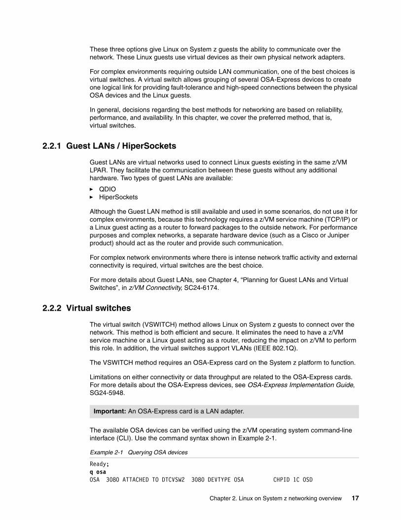
The available OSA devices can be verified using the z/VM operating system command-line interface (CLI). Use the command syntax shown in Example 2-1.
Example 2-1 Querying OSA devices
Ready;q osa OSA 3080 ATTACHED TO DTCVSW2 3080 DEVTYPE OSA CHPID 1C OSD
Important: An OSA-Express card is a LAN adapter.
Chapter 2. Linux on System z networking overview 17
OSA 3081 ATTACHED TO DTCVSW2 3081 DEVTYPE OSA CHPID 1C OSD OSA 3082 ATTACHED TO DTCVSW2 3082 DEVTYPE OSA CHPID 1C OSD OSA 30A0 ATTACHED TO DTCVSW1 30A0 DEVTYPE OSA CHPID 1E OSD OSA 30A1 ATTACHED TO DTCVSW1 30A1 DEVTYPE OSA CHPID 1E OSD OSA 30A2 ATTACHED TO DTCVSW1 30A2 DEVTYPE OSA CHPID 1E OSD
A sample of a virtual switch is shown in Figure 2-1.
Figure 2-1 z/VM virtual switch network
Transport modesOSA-Express devices allow communication with IP (Layer 3) and non-IP (Layer 2) transport modes. The protocol used should be carefully selected if the OSA-Express device is being shared with other LPARs.
Important: Ensure that you have privilege class B to run the QUERY OSA command.
z/VM 1
Linux 1 Linux 2
Virtual Switch
OSA Device
NIC NIC
Virtual Switch
LAN
Linux 3 Linux 4
NIC NIC
OSA Device
OSA Device OSA Device
18 Advanced Networking Concepts Applied Using Linux on IBM System z
The following information should be kept in mind when making a decision:
� A Layer 2 VSWITCH cannot be shared with both an IBM z/OS® and z/VM TCP/IP stack, but can be shared with another Layer 2 VSWITCH.
� A Layer 3 VSWITCH can be shared with a z/VM and z/OS TCP/IP stack.
� OSA ports per z/OS and z/VM TCP/IP stack can be shared.
� VSWITCH LACP OSA ports must be dedicated.
It is equally important to note that layer 2 and layer 3 transport modes have differences:
� IP (Layer 2) mode
– Optional for VSWITCH / LAN.
– Forwards both IP and non-IP protocols (such as IPX, NetBIOS, or SNA).
– Supports VLAN.
– Each host has or is assigned a unique MAC address.
� IP (Layer 3) mode
– Default for VSWITCH / LAN.
– Forwards only the IP protocol.
– Supports VLAN.
– A unique MAC address is assigned by OSA device, which means that all guests share a MAC address with the adapter.
VLAN aware and unawareUsing a VSWITCH is important during network communications when running Linux guests under z/VM. There are two operation options (aware and unaware) that are available for virtual switches. Carefully select your option because it changes the behavior of how virtual switches handle and process packages and frames. Depending on what option you select, the virtual switch ignores or processes the VLAN tags.
VLAN aware: In this mode, the virtual switch reads and handles VLAN tags. The switch port that is connected to the OSA-Express port must be configured as a trunk port (check with your network administrator). The trunk port carries traffic from all VLANs.
VLAN unaware: In this mode, the virtual switch ignores VLAN tags. The switch port that is connected to the OSA-Express port must be configured as an access port (check with your network administrator). The access port carries traffic for a single VLAN.
To create a Layer 3 virtual switch (VLAN unaware is the default), run the command shown in Example 2-2.
Example 2-2 Creating a Layer 3 VSWITCH with VLAN unaware
DEFINE VSWITCH VSWITCH1 RDEV 3080 30A0
To create a Layer 2 virtual switch using VLAN aware, run the command shown in Example 2-3.
For more information: For specific information about how to define the virtual switches and NICs, see z/VM Connectivity, SC24-6174.
Chapter 2. Linux on System z networking overview 19
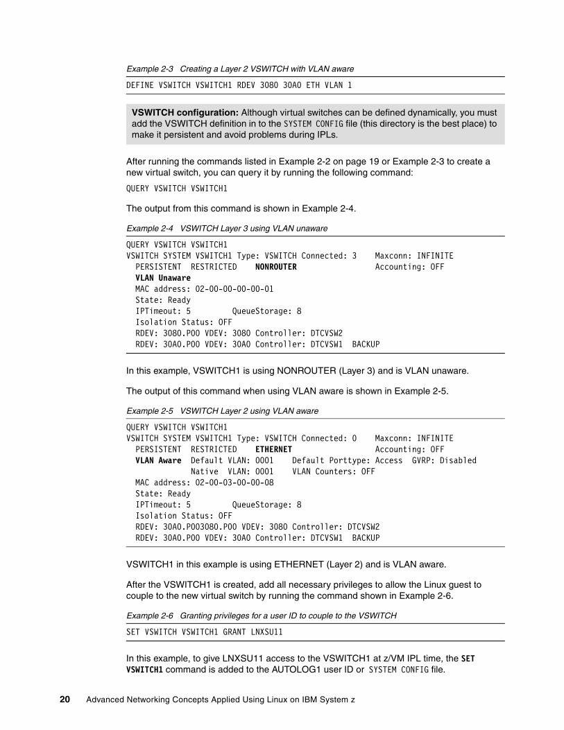
Example 2-3 Creating a Layer 2 VSWITCH with VLAN aware
DEFINE VSWITCH VSWITCH1 RDEV 3080 30A0 ETH VLAN 1
After running the commands listed in Example 2-2 on page 19 or Example 2-3 to create a new virtual switch, you can query it by running the following command:
QUERY VSWITCH VSWITCH1
The output from this command is shown in Example 2-4.
VSWITCH1 in this example is using ETHERNET (Layer 2) and is VLAN aware.
After the VSWITCH1 is created, add all necessary privileges to allow the Linux guest to couple to the new virtual switch by running the command shown in Example 2-6.
Example 2-6 Granting privileges for a user ID to couple to the VSWITCH
SET VSWITCH VSWITCH1 GRANT LNXSU11
In this example, to give LNXSU11 access to the VSWITCH1 at z/VM IPL time, the SET VSWITCH1 command is added to the AUTOLOG1 user ID or SYSTEM CONFIG file.
VSWITCH configuration: Although virtual switches can be defined dynamically, you must add the VSWITCH definition in to the SYSTEM CONFIG file (this directory is the best place) to make it persistent and avoid problems during IPLs.
20 Advanced Networking Concepts Applied Using Linux on IBM System z
After running this command, LNXSU11 has the authority to couple to VSWITCH1. Example 2-7 shows the command that lists all the user IDs that have enough privileges to couple to VSWITCH1.
Example 2-7 Listing the VSWITCH access list
q vswitch vswitch1 accesslist
This command produces the output shown in Example 2-8. You can see that LNXSU11 is authorized and can couple to VSWITCH1.
Example 2-8 Listing the VSWITCH access list
VSWITCH SYSTEM VSWITCH1 Type: VSWITCH Connected: 3 Maxconn: INFINITE PERSISTENT RESTRICTED NONROUTER Accounting: OFF VLAN Unaware MAC address: 02-00-00-00-00-01 State: Ready IPTimeout: 5 QueueStorage: 8 Isolation Status: OFF Authorized userids: LNXRH56 LNXSU11 SYSTEM TCPIP RDEV: 3080.P00 VDEV: 3080 Controller: DTCVSW2 RDEV: 30A0.P00 VDEV: 30A0 Controller: DTCVSW1 BACKUP
Create the virtual NIC device (Example 2-9).
Example 2-9 Defining a virtual network device
define nic c200 type qdio dev 3
After the network hardware (the NIC) is created, you can couple it to the VSWITCH. While connected to the LNXSU11 server console, run the command shown in Example 2-10 to dynamically couple a network interface previously defined to VSWITCH1.
Example 2-10 Coupling the NIC device to VSWITCH1
couple c200 system VSWITCH1
The output for the couple command is shown in Example 2-9.
Example 2-11 LNXSU11 coupled to VSWITCH1
NIC C200 is connected to VSWITCH SYSTEM VSWITCH1
2.2.3 Setting the vmcp module to be loaded during boot
Using the s390-tools package installed on Linux on System z, you can issue CP commands from a Linux guest to z/VM using the vmcp module. By default, this module is not loaded at boot time.
Chapter 2. Linux on System z networking overview 21
To avoid loading this module every time, enable the vmcp module to load at boot time as follows:
� On SUSE Linux
Add the following command to the /etc/sysconfig/kernel and run SuSEconfig afterward:
MODULES_LOADED_ON_BOOT="vmcp"
� On Red Hat Linux
Add modprobe vmcp to the /etc/rc.d/rc.local file.
Now the system loads the vmcp module during boot time. The module can be loaded for the current session by running the following command:
modprobe vmcp
To see if the vmcp module is loaded on either SUSE or Red Hat, run the following command:
vmcp q userid
2.2.4 Modifying VSWITCH from layer 3 to layer 2
In some circumstances, you might need to modify your VSWITCH to accommodate a specific network configuration. To change the VSWITCH from Layer 3 to Layer 2 for VSWITCH1, complete the following steps:
1. Connect to the Linux guest:
a. Take down the interface by running the following command:
/sbin/ifdown eth0
b. Detach the NIC from the Linux guest by running the following command:
/sbin/vmcp det nic 1e00
c. Uncouple the virtual NIC (in our example, c200) from the Layer 3 VSWITCH by running the following command:
/sbin/vmcp uncouple c200 system VSWITCH1
2. Connect to z/VM:
a. Redefine VSWITCH1 to change the transport mode from Layer 3 to Layer 2 by running the following commands:
b. Grant the guest authorization to connect to the Layer 2 VSWITCH by running the following command:
SET VSWITCH VSWITCH1 GRANT LNXSU11
c. Update the SYSTEM CONFIG file to reflect the new configuration.
3. Connect again to the Linux guest:
a. Couple the virtual NIC (c200) to the Layer 2 VSWITCH by running the following command:
/sbin/vmcp couple c200 system VSWITCH1
Options: 3080 and 30A0 are the device OSA card numbers.
22 Advanced Networking Concepts Applied Using Linux on IBM System z
b. Start the interface by running the following command:
/sbin/ifup eth0
2.2.5 The qeth driver
For z/VM on System z10 and later hardware, communications between OSA-Express devices and the qeth device driver are available by using the Queued Direct I/O (QDIO) protocol. In addition, all devices are represented by a folder under the /sys file system when the qeth module is loaded.
The qeth device driver requires three I/O subchannels (Channel Command Word (CCW) devices for read, write, and data) for each OSA-Express CHPID predefined in your Input Output Control Data Set (IOCDS).
To define a qeth group device, issue the command shown in Example 2-12.
The qeth file: /sys/bus/ccwgroup/drivers/qeth is created when the qeth module loads.
Name Description Example
read_device_id Must be even c200
write_device_id Must be the device bus-ID of the read subchannel plus one
c201
data_device_id Might be the device bus-ID of the write subchannel plus one
c202
Chapter 2. Linux on System z networking overview 23
Optionally, you can set additional parameters and features to attend a specific need. For example, portno and Layer 2 can be modified, but these modifications depend on the way your network is set up. If you need additional information, see Linux on System z - Device Drivers, Features, and Commands, SC33-8289.
2.3 Important Linux network files
This section describes some Linux configuration files located in the /etc directory. These files are used to set up a network on a Linux guest. These files are automatically created during a Linux installation, but you should know how to modify these initial settings whenever you need to change an IP address, add an interface, or need help with troubleshooting.
2.3.1 SUSE Linux Enterprise Server 11 configuration files
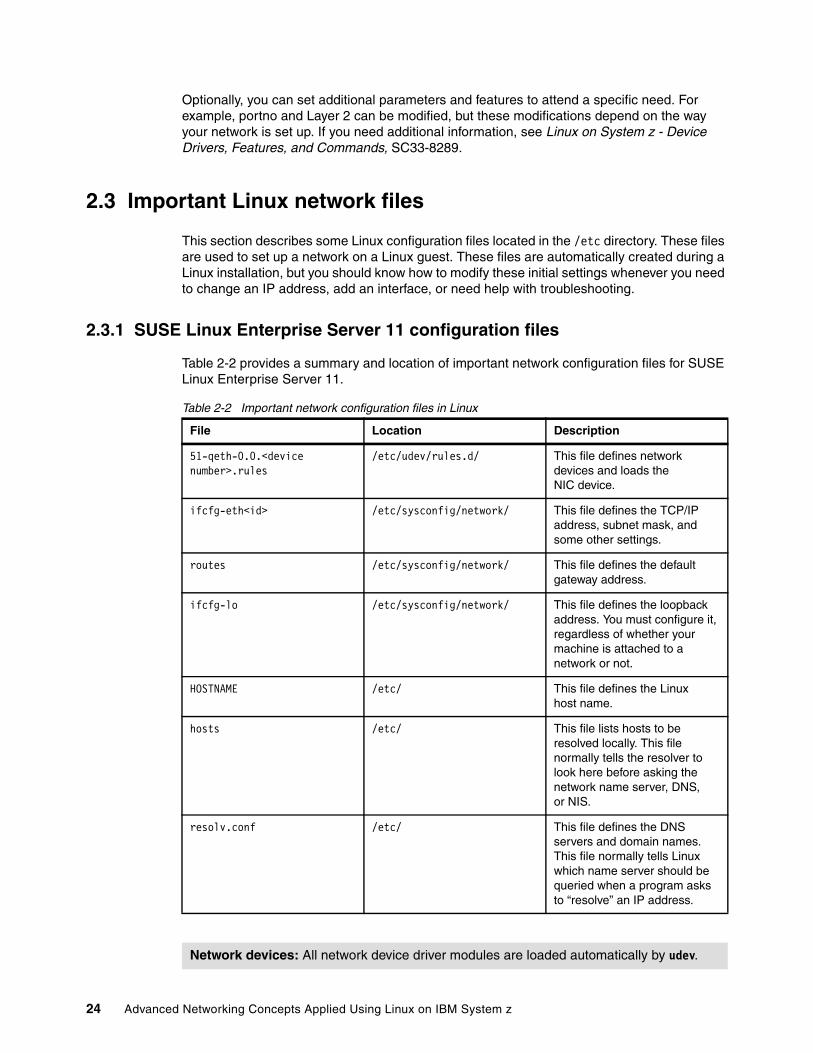
Table 2-2 provides a summary and location of important network configuration files for SUSE Linux Enterprise Server 11.
Table 2-2 Important network configuration files in Linux
File Location Description
51-qeth-0.0.<device number>.rules
/etc/udev/rules.d/ This file defines network devices and loads the NIC device.
ifcfg-eth<id> /etc/sysconfig/network/ This file defines the TCP/IP address, subnet mask, and some other settings.
routes /etc/sysconfig/network/ This file defines the default gateway address.
ifcfg-lo /etc/sysconfig/network/ This file defines the loopback address. You must configure it, regardless of whether your machine is attached to a network or not.
HOSTNAME /etc/ This file defines the Linuxhost name.
hosts /etc/ This file lists hosts to be resolved locally. This file normally tells the resolver to look here before asking the network name server, DNS, or NIS.
resolv.conf /etc/ This file defines the DNS servers and domain names. This file normally tells Linux which name server should be queried when a program asks to “resolve” an IP address.
Network devices: All network device driver modules are loaded automatically by udev.
24 Advanced Networking Concepts Applied Using Linux on IBM System z
Network devices are activated during boot time and require some settings to be loaded during the initialization phase. For each network device, you should have a hardware configuration file and a logical interface configuration file (with a 1:1 relationship). The location for each file is listed in Table 2-3. The network card module (qeth) should be detected and loaded automatically at startup and IP addresses assigned afterward.
Because udev is being used to load devices on SUSE Linux Enterprise Server 11, the old configuration files (/etc/sysconfig/network/ifcfg-qeth-bus-ccw-*) are no longer used.
The naming convention for the new hardware file is 51-<device type>-<bus location>.rules and for the logical interface file is ifcfg-<interface name>. Both can be edited as necessary to adjust attributes to best fit your network configuration
Table 2-3 lists the directories used to keep the network configuration files in.
Table 2-3 Directory locations
Hardware configuration fileThe new hardware configuration file (51-<device type>-<bus location>.rules) has parameters to load the qeth module at boot time and to bring the network interface online. Most of the network problems with qeth are related to misconfiguration on the Layer 2 attribute listed in this file.
When configuring a device in Linux on System z, the qeth driver reads the parameters in the hardware configuration file before loading. One of these parameters is the transport mode, which can be layer 2 or layer 3. The z/VM VSWITCH dictates which value is used in the hardware configuration file for the stanza (ATTR{layer2}). The following rules are used:
� If the z/VM VSWITCH is using Layer 2 transport mode, the stanza ATTR{layer2} inside the hardware configuration file needs to be set to 1 (ATTR{layer2}="1").
� If the z/VM VSWITCH is using Layer 3 transport mode, the stanza ATTR{layer2} inside the hardware configuration file needs to be set to 0 (ATTR{layer2}="0").
Important: Files in /etc/udev/rules.d/ are automatically created during installation or upon device detection.
Chapter 2. Linux on System z networking overview 25
Figure 2-2 lists sample contents of the udev rules file for the c200 device in our lab environment. The file name for this device is 51-qeth-0.0.c200.rules.
Figure 2-2 Contents of the udev rules file for the c200 device -51-qeth-0.0.c200.rules file
Logical interface configuration fileThe logical interface file contains the TCP/IP information for a specific network interface (except for the default gateway, which is configured in the routes file). The file naming convention for the logical interface file is ifcfg-<interface name>. An example of this file can be found in Figure 2-3.
Important: Each device must be represented by one hardware configuration file and one logical Interface configuration file.
26 Advanced Networking Concepts Applied Using Linux on IBM System z
2.3.2 Red Hat configuration files
Comparing SLES 11 to Red Hat Enterprise Linux, different files are used to set up a network. See Table 2-4 for more information about the Red Hat configuration files.
Table 2-4 Red Hat network configuration files
2.3.3 How to add a qeth device manually
This section describes a step-by-step procedure to activate a network configuration on a Linux guest using a qeth device. Most of the commands listed here can be used during network troubleshooting.
1. Determine the three OSA card numbers. These numbers must match the ones you defined either by running DEFINE NIC or by setting the NICDEF statement in the user’s directory file. Connect to the Linux guest console and issue the command shown in Example 2-16 to show the virtual device defined (c200).
Example 2-16 Querying the virtual NIC
vmcp query nicAdapter C200.P00 Type: QDIO Name: any Devices: 3 MAC: 02-00-00-00-00-03 VSWITCH: SYSTEM VSWITCH1
2. Load the qeth module (Example 2-17).
Example 2-17 Loading the qeth module
modprobe qeth
3. Initiate a network group device (Example 2-18).
/etc/sysconfig/network-scripts/ifcfg-eth0 This file is the network device configuration file (logical interface configuration). It contains information about the IP addresses, subnet address, and network options.
/etc/modprobe.conf This file is the module configuration file. It is used to load the qeth device.
/etc/sysconfig/network This file defines the default gateway address and server host name.
Virtual device: c200 is the virtual device number of VSWITCH1 in the ITSO lab environment.
Chapter 2. Linux on System z networking overview 27
5. Create the /etc/sysconfig/network/ifcfg-eth0 file (Example 2-20).
Example 2-20 Sample of the ifcfg-eth0 configuration file
For many network administrators, the Layer 2 configuration can be confusing and lead to problems for Linux on System z guests. A misconfiguration of Layer 2 settings can lead to LAN connectivity issues. Different approaches are available to remedy this situation. In this section, we describe some situations involving these problems.
2.4.1 Inter-User Communication Vehicle
It is difficult to edit Linux files or debug network problems when Linux guests are not connected to a network. When you use a 3270 emulator to access a Linux guest, the emulator does not handle oversize panels correctly and does not allow Linux administrators to use their favorite Linux editors. A great alternative to the 3270 terminal is the IUCV, which allows Linux administrators to connect to Linux guests without a network connection. The administrators access the Linux guests in similar way when using an SSH or telnet session.
To enable IUCV, you need to install the s390-tools package, which should be available with your Linux distribution (SLES or Red Hat).
To use IUCV connections within a virtual Linux server farm on z/VM to access terminal devices on Linux instances, go to the following website:
A common problem with the qeth device might be related to the hardware configuration file. Software updates or manual changes in the /etc/udev/rules.d/51-qeth-0.0.xxxx.rules file can lead to a network problem. Check if the online attribute is listed at the end of the file. To accomplish this task, first check if the qeth device is loaded by listing the startup messages for qeth (Example 2-23).
Example 2-23 Command to list startup messages for the qeth device
/bin/dmesg |grep qeth
Example 2-24 shows a sample of output of this command.
Example 2-24 dmesg command output
qeth.87067b: loading core functions qeth.933eb7: register layer 2 discipline qeth.5cb8a3: 0.0.c200: The qeth device is not configured for the OSI layer required by z/VM qeth.3acf0c: 0.0.c200: The qeth device driver failed to recover an error on the device qeth: irb 00000000: 00 c2 60 17 02 3e a0 38 0e 00 10 00 00 80 00 00 qeth: irb 00000010: 01 02 00 00 00 00 00 00 00 00 00 00 00 00 00 00qeth: sense data 00000000: 02 00 00 00 00 00 00 00 00 00 00 00 00 00 00 00 qeth: sense data 00000010: 00 00 00 00 00 00 00 00 00 00 00 00 00 00 00 00 qeth.3acf0c: 0.0.c200: The qeth device driver failed to recover an error on the device qeth.2c6def: register layer 3 discipline
The qeth module reads the hardware configuration file from top to bottom. If the online attribute is not listed at the end of the file, some parameters such as Layer 2 may not be read and the interface does not come online. Make sure that the online attribute appears after all other attributes (Example 2-25). An incorrect order might prevent the qeth device from coming online.
Example 2-25 Excerpt of the /etc/udev/rules.d/51-qeth-0.0.c200.rules file showing the correct order for the online attribute
2.4.3 Layer 2 mismatch in the VSWITCH configuration
Running dmesg|grep qeth shows the startup messages for qeth initialization or error messages if the initialization fails. If the Layer 2 setting in the Linux hardware configuration file does not match the VSWITCH, you get the error listed in Example 2-26, where the qeth driver failed to bring the device online.
Example 2-26 Output error for a Layer 2 misconfiguration
Chapter 2. Linux on System z networking overview 29
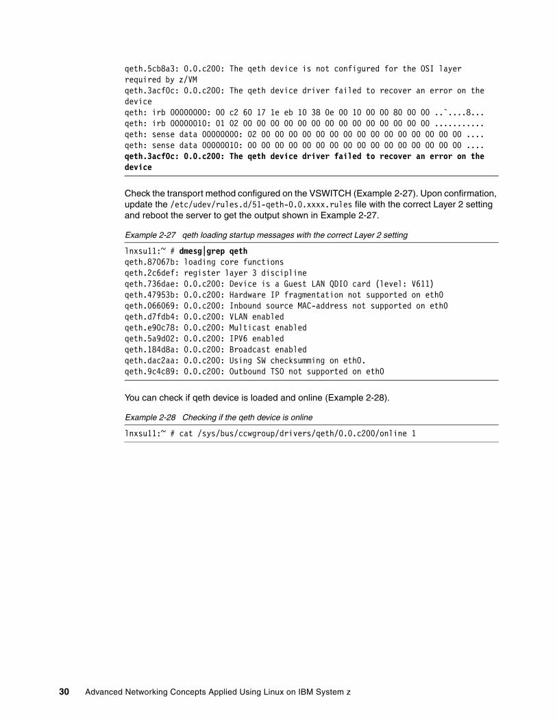
qeth.5cb8a3: 0.0.c200: The qeth device is not configured for the OSI layer required by z/VM qeth.3acf0c: 0.0.c200: The qeth device driver failed to recover an error on the device qeth: irb 00000000: 00 c2 60 17 1e eb 10 38 0e 00 10 00 00 80 00 00 ..`....8...qeth: irb 00000010: 01 02 00 00 00 00 00 00 00 00 00 00 00 00 00 00 ...........qeth: sense data 00000000: 02 00 00 00 00 00 00 00 00 00 00 00 00 00 00 00 ....qeth: sense data 00000010: 00 00 00 00 00 00 00 00 00 00 00 00 00 00 00 00 ....qeth.3acf0c: 0.0.c200: The qeth device driver failed to recover an error on the device
Check the transport method configured on the VSWITCH (Example 2-27). Upon confirmation, update the /etc/udev/rules.d/51-qeth-0.0.xxxx.rules file with the correct Layer 2 setting and reboot the server to get the output shown in Example 2-27.
Example 2-27 qeth loading startup messages with the correct Layer 2 setting
lnxsu11:~ # dmesg|grep qethqeth.87067b: loading core functionsqeth.2c6def: register layer 3 disciplineqeth.736dae: 0.0.c200: Device is a Guest LAN QDIO card (level: V611)qeth.47953b: 0.0.c200: Hardware IP fragmentation not supported on eth0qeth.066069: 0.0.c200: Inbound source MAC-address not supported on eth0qeth.d7fdb4: 0.0.c200: VLAN enabledqeth.e90c78: 0.0.c200: Multicast enabledqeth.5a9d02: 0.0.c200: IPV6 enabledqeth.184d8a: 0.0.c200: Broadcast enabledqeth.dac2aa: 0.0.c200: Using SW checksumming on eth0.qeth.9c4c89: 0.0.c200: Outbound TSO not supported on eth0
You can check if qeth device is loaded and online (Example 2-28).
Example 2-28 Checking if the qeth device is online
30 Advanced Networking Concepts Applied Using Linux on IBM System z
Chapter 3. Linux networking tools
This chapter introduces the main Linux networking commands and configuration files. These tools provide for the setup, monitoring, diagnosing, and measuring of the performance of a network. After reading this chapter, you will be able to translate network concepts into a Linux setup.
This chapter is not an ultimate resource for network configuration or the commands. It briefly describes how you can set up a network and change and monitor it. This chapter also describes the main topics that help you and how or where you can get more help if needed.
In this section, we describe managing network interface parameters, using names in place of IP addresses, routing packets throughout the network, and managing applications.
3.1.1 Managing network interface parameters
When managing your network, there are times where you need to configure or show network interface parameters for the network using TCP/IP.
You can run ifconfig to assign an address to a network interface and to configure or show the current network interface configuration information. The ifconfig command must be used at system startup after a fresh installation to define the network address of each interface present on a machine.
The ifconfig command is found in many *nix type systems, which is used to configure network interfaces. Using this command with no arguments provides the status of the currently active interfaces (Example 3-1).
The ifconfig command can also be used to bring a network interface online or offline. This task is accomplished by providing the interface name to the ifconfig command followed by the option “up” or “down” (Example 3-2).
Example 3-2 Enabling and disabling a network interface
ifconfig can also be used to set the IP address used by the interface. To set the IP address, the ifconfig command should be followed by the interface name and the IP address to assign (Example 3-3).
Example 3-3 Setting the IP address of an interface using ifconfig
The ifconfig command can also be used for IP aliasing. IP aliasing is when one network interface has many IP addresses. The method for creating IP aliases is simple, as demonstrated in Example 3-4.
With the first command, we set the alias of the eth0 IP address (which has an IP address of 10.52.52.97) to eth0:1 with an IP address of 10.52.52.96. Before this command, if you had sent a ping command to 10.52.52.96, it would fail to return a response. After the command, you receive a normal ping response.
34 Advanced Networking Concepts Applied Using Linux on IBM System z
Another useful configuration for setting up an IP address is to see if the interface is configured to use static IP addresses or use Dynamic Host Configuration Protocol (DHCP), which is an autoconfiguration protocol used on IP networks. This configuration can be found in the /etc/sysconfig/network-scripts/ifcfg-xxxx file, where xxxx is the interface name, for example, eth0, eth1, and so on. The BOOTPROTO entry states whether the interface is configured to use a static IP address or DHCP (Example 3-5).
Example 3-5 Determine if the interface is configured to use static IP or DHCP
In this example, the interface is configured to use a static IP address.
3.1.2 Names
A convenient way to remember IP addresses is to assign a name to them. This name is called the host name. The host names of devices are set in the /etc/hosts file. The structure of the entries in the hosts file is simple: It is the IP address followed by a space and the name (Example 3-6).
Example 3-6 Host name resolving with /etc/hosts
srilnx1:~ # tail -1 /etc/hosts10.52.52.93 srilnx1.itso.ibm.com srilnx1srilnx1:~ # ping srilnx1PING srilnx1.itso.ibm.com (10.52.52.93) 56(84) bytes of data.64 bytes from srilnx1.itso.ibm.com (10.52.52.93): icmp_seq=1 ttl=64 time=0.022 ms64 bytes from srilnx1.itso.ibm.com (10.52.52.93): icmp_seq=2 ttl=64 time=0.046 ms^C--- srilnx1.itso.ibm.com ping statistics ---2 packets transmitted, 2 received, 0% packet loss, time 999msrtt min/avg/max/mdev = 0.022/0.034/0.046/0.012 ms
The line 10.52.52.93 srilnx1.itso.ibm.com srilnx1 defines the srilnx1 host name to point to the IP address 10.52.52.93. Whenever the ping command is run with the srilnx1 option, the IP address that is returned is 10.52.52.93.
The next process used for resolving an IP address is the resolver. It uses a Domain Name Service (DNS) for IP address resolution. You must have a resolv.conf file to resolve an IP address, which is the configuration file that is used to find the name servers. It is named /etc/resolv.conf. Example 3-7 shows the contents of a sample resolv.conf file.
Example 3-7 /etc/resolv.conf
srilnx1:~$ cat /etc/resolv.conf# Generated by NetworkManagerdomain pok.ibm.comsearch pok.ibm.comnameserver 9.0.2.1nameserver 9.0.3.1
Chapter 3. Linux networking tools 35
As shown in this sample configuration file, the name servers that are defined are 9.0.2.1 and 9.0.3.1.
3.1.3 Routing
The next step in networking is routing packets throughout the network. There are many commands that can be used for this step, but the one of the most commonly used commands is the route command. This command allows the user to change the kernel’s routing table. In Example 3-8, the command adds a route to the 192.56.76.* network through the eth0 device.
Example 3-8 Route to 192.56.76.* through eth0
srilnx1:~ # route add -net 192.56.76.0 netmask 255.255.255.0 dev eth0srilnx1:~ # routeKernel IP routing tableDestination Gateway Genmask Flags Metric Ref Use Iface192.56.76.0 * 255.255.255.0 U 0 0 0 eth010.0.0.0 * 255.0.0.0 U 0 0 0 eth0loopback * 255.0.0.0 U 0 0 0 losrilnx1:~ #
You can delete the route by specifying the del option with the route command (Example 3-9).
Example 3-9 Deleting a route
srilnx1:~ # route del -net 192.56.76.0 netmask 255.255.255.0 dev eth0srilnx1:~ # routeKernel IP routing tableDestination Gateway Genmask Flags Metric Ref Use Iface10.0.0.0 * 255.0.0.0 U 0 0 0 eth0loopback * 255.0.0.0 U 0 0 0 losrilnx1:~ #
3.1.4 Applications management
An part of networking is the applications using the network. A common setup is for daemons to listen on ports and wait for a client to make a connection. Most of the time, the daemons are idle and use up system resources. To prevent this usage from happening, a program named xinetd is used. The xinetd is considered to be a super server. Instead of many daemons running and listening for client connections, only xinetd is listening on a certain port for client connections. After the client connects to xinetd, then the xinetd program takes care of the request by starting the appropriate program. With this method, you gain performance by eliminating the idling processes.
There are many useful commands that can be used to administer xinetd on your system. Example 3-10 shows how to check the status of the xinetd daemon on your system.
Example 3-10 xinetd status
srilnx1:~ # /etc/init.d/xinetd statusChecking for service xinetd: runningsrilnx1:~ #
36 Advanced Networking Concepts Applied Using Linux on IBM System z
This command is used to see the status of xinetd. Example 3-11 shows how to stop the program and then check the status after it has stopped.
Example 3-11 Stop xinetd
srilnx1:~ # /etc/init.d/xinetd stopShutting down xinetd: (waiting for all children to terminate) donesrilnx1:~ # /etc/init.d/xinetd statusChecking for service xinetd: unusedsrilnx1:~ #
Now that the instance has stopped, start it again (Example 3-12).
Example 3-12 Start xinetd
srilnx1:~ # /etc/init.d/xinetd startStarting INET services. (xinetd) donesrilnx1:~ # /etc/init.d/xinetd statusChecking for service xinetd: runningsrilnx1:~ #
To cycle the xinetd daemon without needing to perform the start and stop commands separately, run restart (Example 3-13).
Example 3-13 Restart xinetd
srilnx1:~ # /etc/init.d/xinetd restartShutting down xinetd: (waiting for all children to terminate) doneStarting INET services. (xinetd) donesrilnx1:~ # /etc/init.d/xinetd statusChecking for service xinetd: runningsrilnx1:~ #
You now know how to control the xinetd daemon itself. Now we can take a look at the basic configuration behind it. The global xinetd configuration file is located in /etc/xinetd.conf. The service-specific files are located in the /etc/xinetd.d/ directory. Example 3-14 shows a sample global xinetd configuration file.
## The specification of an interface is interesting, if we are on a firewall.# For example, if you only want to provide services from an internal# network interface, you may specify your internal interfaces IP-Address.## interface = 127.0.0.1
}
includedir /etc/xinetd.d
In Example 2-14:
� The log_type field sets the location of the xinetd log file.
� The log_on_success field logs whether the connection is successful, and it logs the host name and the Process ID for that instance. The log_on_failure field logs the host name if the connection failed.
� The cps field limits the rate of incoming connections. This field uses two arguments: the number connections per second and the number of seconds to disable the service if the number of connections received is more than the number specified in the first argument. This setting is useful for preventing denial of service (DOS) attacks.
For example, setting cps = 50 10 allows 50 connections and disables the service if the number of connection requests exceeds that amount. The time duration for disabling the service is the second argument, which is 10 seconds in this example.
� The includedir field directs xinetd to read the directory specified in the argument for more service-specific configurations.
3.2 Monitoring, diagnosing, and measuring the performance of the network
After configuring and starting the network, you can use some useful tools to perform maintenance.
Secure Shell (SSH) is a program that allows connections and command execution remotely and securely. It connects two servers independent of the location and the infrastructure along the path. It needs a routing path allowing access. It provides encrypted security over untrusted hosts and insecure networks. OpenSSH is the no cost version of the SSH used by Linux distributions.
SSH is a client / server program, part of the OpenSSH set. The configuration files can be found under the /etc/ssh directory. This path has cryptographic keys and two main configuration files: ssh_config for client-side configuration and sshd_config for server-side configuration. Both files come pre-configured and usable by default and also come with a complete set of comments within the files, making it easy to modify as needed.
SUSE Linux Enterprise Server (SLES) 11 has both client and servers packaged inside the same OpenSSH package. Red Hat Enterprise Linux (RHEL) uses two separated packages: openssh-server on the server side and openssh-clients for the client side.
38 Advanced Networking Concepts Applied Using Linux on IBM System z
The server-side configuration is simple and the comments inside the configuration file are helpful if the administrator needs to implement changes. The configuration file main options are the port (if you do not want to use the default port of port 22) to define where to listen for connections, and the ones related to authentication methods. Example 3-15 shows the SSH configuration file.
Example 3-15 An example of the SSH configuration file
You can connect from a client to the remote server where you installed the SSH server. You must use an existing user on the remote system, which holds the server. To connect, run ssh (Example 3-16).
Example 3-16 Logging in from a client to a remote server by running ssh
If you do not explicitly name the user, SSH tries to connect to the current user. In Example 3-16, you could omit the root user and achieve the same results.
To avoid typing the password for each connection, use SSH keys. To create one, run ssh-keygen (Example 3-17).
Example 3-17 Generating an ssh key using the ssh-keygen command
lnxlocal:~./ssh # ssh-keygenGenerating public/private rsa key pair.Enter file in which to save the key (/root/.ssh/id_rsa):Enter passphrase (empty for no passphrase):Enter same passphrase again:Your identification has been saved in /root/.ssh/id_rsa.Your public key has been saved in /root/.ssh/id_rsa.pub.The key fingerprint is:e9:ae:aa:48:1f:cf:5f:46:af:b1:94:6a:31:38:8c:df root@lnxlocalThe key's randomart image is:+--[ RSA 2048]----+| || || || . || o . S. || . + +. o || . .. o +* . ||... +. E= + |
Chapter 3. Linux networking tools 39
|. .o.+++.o |+-----------------+
This command creates two files in the ./ssh/ directory: id_rsa, which contains the private key, and id_rsa.pub, which contains the public key. The content of id_rsa.pub has the same format (Example 3-18).
Example 3-18 Example of a generated id_rsa.pub file
This content needs to be stored in the .ssh/authorized_keys file on the remote server (Example 3-19). The remote server, lnxremote in this example, must also have the correct permissions.
Now it is possible to log in without being prompted for a password (Example 3-20) because the servers know and trust each other, and are working over a secure connection. This authentication only works in one direction, in our example, for connections from lnxlocal to lnxremote. To enable the authentication to work in the other direction, you need to repeat the same steps shown in Example 3-19. Set the server configurations for lnxlocal, generate keys on lnxremote, and share the public key available on the user’s directory of lnxlocal.
Example 3-20 Connection to a remote server using an ssh key instead of a password
For the client side, there are two configuration files. The first file, /etc/ssh/ssh_config, defines general guidelines for client usage. The main function is to have a global file to limit the usage of SSH by system users. In this sense, this file often is almost empty (with a few comments and options). The main option is shown in Example 3-21:
Example 3-21 An example of /etc/ssh/ssh_config
Host *SendEnv LANG LC_*HashKnownHosts yesGSSAPIAuthentication yesGSSAPIDelegateCredentials no
40 Advanced Networking Concepts Applied Using Linux on IBM System z
The second client configuration file is in the users directory and is named config, such as ~/.ssh/config. Example 3-22 shows an example:
Example 3-22 An example of ~/.ssh/config
Compression yesCompressionLevel 9
# My servers’ name aliases:
Host lnxremote server1 rh56Hostname lnxremote.mynetwork.comUser jon
One advantage of SSH is the provisioning of a secure connection over an insecure network path between untrusted systems. Two specific configurations make daily management even easier:
� Cryptographic keys to build reliability between two systems for specific users
� The user’s ~/.ssh/config file, enabling client side granular configuration to several servers
The main advantage of using SSH is the facilities introduced by some other tools that take advantage of the SSH channel to handle numerous tasks without worrying about network security:
� scp and sftp
These tools are part of the openssh or openssh-clients packages.
scp is used to copy files between the remote systems.
Chapter 3. Linux networking tools 41
sftp is used to transfer files interactively over the secure SSH connection based on encryption. It connects to other servers and opens an interactive session. It also can retrieve files automatically if an interactive authentication method is not available. It starts in a remote directory and proceeds to automated sessions (the public key authentication method is required).
� rsync
This tool is a versatile copying tool. Use it when you have more than a couple of files to transfer. It also helps when transferring disk partitions, nested directories, and large amounts of data. rsync can be used locally as well. The connection between the two hosts has three phases:
a. Authentication: SSH prepares the secure path.
b. Building of the file list: The rsync tool investigates the differences between the source and the target content, so it transfers only what needs to be transferred. This phase is the core of the rsync process and is effective.
c. Data transfer: Based on the built file list.
The main usage of rsync is for mirroring servers, FTP servers, backup management servers, and all the servers that deal with moving data that changes often.
� bash process substitution
This process uses SSH to perform almost every possible local action at remote servers. So, if the user needs to compare two files in remote hosts and print the lines that are different (using the diff command), it can be done.
It is also possible to manipulate multiple elements on different remote servers, using the format found in Example 3-24.
Example 3-24 Multiple elements on different remote servers
Other tools that use SSH as a base for remote access are:
� Virtual private networks (VPN) over SSH
� A remote graphical desktop (with VPN or exporting X11 terminals)
� Repository management, such as git, svn or cvs, audio over SSH, FTP over SSH, and so on
OpenSSH is useful for network management, because it enables secure tunnels over all the hosts when routes are possible.
3.2.2 Basic network protocols
This chapter provides an overview of the most important and common protocols associated with the network layer. These protocols include:
� Internet Protocol (IP)� Internet Control Message Protocol (ICMP)� Simple Network Management Protocol (SNMP)� Transmission Control Protocol (TCP) and User Datagram Protocol (UDP)
These protocols perform datagram addressing, routing and delivery, and managing devices. These protocols are considered either connection-oriented or connectionless protocols.
42 Advanced Networking Concepts Applied Using Linux on IBM System z
Internet Protocol (IP)This protocol is the main method used to deliver datagrams from a source (host) to a destination. This delivery is done solely based on numeric addresses.
There are two major versions of IP in the current industry. One version is IPv4, which can be represented in any notation that expresses a 32-bit integer value. To make IPv4 human readable, they are written in dot-decimal format. This format contains four octets expressed individually in decimal form (xxx.xxx.xxx.xxx). They are separated by periods.
Due to the rising scarcity of IPv4 addresses, IPv6 has been developed. IPv6 uses 128-bit addressing so that it can support 2^128 addresses. IPv6 has two logical parts, one 64-bit network prefix, and a 64-bit host address. The IPv6 address is represented by eight groups of 16-bit hexadecimal values separated by “:”.
Internet Control Message Protocol (ICMP)This protocol is one of the core protocols of the IP suite. It is part of the Internet layer. It is used to send error messages in the network, for example, if a host or router cannot be reached. ICMP can also be used to query messages. This protocol is different from other protocols because it is not normally used for data transference. Some important programs for network diagnostic procedures use this protocol. The ping command uses this protocol.
Simple Network Management Protocol (SNMP)This protocol is an Internet standard protocol that is used for managing devices. This protocol is part of the application layer. Devices such as routers, switches, servers, workstations, printers, and modem racks support this protocol. SNMP shows the data required for managing the system in the form of variables. These variables in turn describe the system configuration. These variables can be queried and set by the applications that manage the configurations.
Transmission Control Protocol (TCP) and User Datagram Protocol (UDP) TCP and UDP are two widely used transport layer protocols used in the industry. Unlike UDP, TCP provides reliable delivery of information. Because TCP offers reliability, it takes more time (a magnitude of seconds). TCP is widely used in applications such as email, file transfer protocol (FTP), and so on. When using these applications, the few second delays is negligible to the user. In other situations, such as voice over IP (VOIP), delivery is not as important as the timely arrival of information. In those cases, UDP is used.
3.2.3 Monitoring
There are some useful Linux tools for monitoring networks. One tool is nstat. The nstat command prints networking activity maintained inside the kernel. Example 3-25 shows the output of the nstat command.
One basic command that is used to monitor a network checks to see if a host is reachable from the localhost. This command is the ping command. The ping command sends ICMP packets to see if the packets are reaching the host and show the time that it takes for the replies to arrive. The time shown by the ping command is the round-trip time (RTT). An example of the ping command is shown in Example 3-26.
Example 3-26 ping 10.52.52.94
srilnx1:~ # ping 10.52.52.94PING 10.52.52.94 (10.52.52.94) 56(84) bytes of data.64 bytes from 10.52.52.94: icmp_seq=1 ttl=64 time=0.195 ms64 bytes from 10.52.52.94: icmp_seq=2 ttl=64 time=0.183 ms^C--- 10.52.52.94 ping statistics ---2 packets transmitted, 2 received, 0% packet loss, time 999msrtt min/avg/max/mdev = 0.183/0.189/0.195/0.006 ms
Another tool available in Linux to diagnose a problem related to the network is the nslookup command. This command returns information from the DNS of the given host name. An example of nslookup is shown in Example 3-27.
44 Advanced Networking Concepts Applied Using Linux on IBM System z
If all you need is a simple host resolution without the thorough output provided by nslookup, you can run the host command. Example 3-28 shows the execution of the host command on www.example.com. It performs a host lookup and returns the output from DNS.
Example 3-28 host www.example.com
srilnx1:~$ host www.example.comwww.example.com is an alias for www.l.example.com.www.l.example.com has address XX.125.73.105www.l.example.com has address XX.125.73.106www.l.example.com has address XX.125.73.147www.l.example.com has address XX.125.73.99www.l.example.com has address XX.125.73.103www.l.example.com has address XX.125.73.104
The netstat command described in 3.2.3, “Monitoring” on page 43 can also be used as a diagnostic tool. It can be used to show the status of the network. It lists all the connections made in the network from this computer. Example 3-29 shows the netstat command in action.
You can also fine-tune the netstat output by using parameters. For a list of these parameters, run man netstat.
One useful option for netstat is the -r option, which lists the routing table for the host (Example 3-30).
Example 3-30 netstat -r
srilnx1:~ # netstat -rKernel IP routing tableDestination Gateway Genmask Flags MSS Window irtt Iface10.0.0.0 * 255.0.0.0 U 0 0 0 eth0loopback * 255.0.0.0 U 0 0 0 losrilnx1:~ #
You can also use the ss command. Like the netstat command, you can specify parameters. The available options can be listed by running man ss. A sample execution of the ss command to list TCP connections is shown in Example 3-31.
If the basic diagnostic tools are not enough to solve a problem, there are more complex and robust tools available. The tcpdump command is one such tool. It dumps a description of the contents of packets of a certain interface. If run without any options, the command captures packets indefinitely until SIGTERM is sent to the console (SIGTERM is the signal sent to a process to request its termination). To capture a set number of packets, specify the -c option followed by the number of packets to capture (Example 3-32).
Example 3-32 tcpdump -c 10
srilnx1:~ # tcpdump -c 10tcpdump: verbose output suppressed, use -v or -vv for full protocol decodelistening on eth0, link-type EN10MB (Ethernet), capture size 96 bytes17:21:13.213184 IP srilnx1.itso.ibm.com.ssh > 10.52.53.6.ansoft-lm-1: P 15575858 82:1557586078(196) ack 1240759620 win 4013617:21:13.214697 IP srilnx1.itso.ibm.com.ssh > 10.52.53.6.ansoft-lm-1: P 196:360( 164) ack 1 win 4013617:21:13.217926 IP 10.52.53.6.ansoft-lm-1 > srilnx1.itso.ibm.com.ssh: . ack 360 win 6424017:21:13.224716 IP srilnx1.itso.ibm.com.ssh > 10.52.53.6.ansoft-lm-1: P 360:604( 244) ack 1 win 4013617:21:13.234730 IP srilnx1.itso.ibm.com.ssh > 10.52.53.6.ansoft-lm-1: P 604:752( 148) ack 1 win 40136
48 Advanced Networking Concepts Applied Using Linux on IBM System z
17:21:13.238692 IP 10.52.53.6.ansoft-lm-1 > srilnx1.itso.ibm.com.ssh: . ack 752 win 6384817:21:13.244682 IP srilnx1.itso.ibm.com.ssh > 10.52.53.6.ansoft-lm-1: P 752:996( 244) ack 1 win 4013617:21:13.248063 IP 10.52.53.6.ansoft-lm-1 > srilnx1.itso.ibm.com.ssh: P 1:85(84) ack 996 win 6360417:21:13.248155 IP 10.52.53.6.ansoft-lm-1 > srilnx1.itso.ibm.com.ssh: P 85:137(5 2) ack 996 win 6360417:21:13.248189 IP srilnx1.itso.ibm.com.ssh > 10.52.53.6.ansoft-lm-1: . ack 137 win 4013610 packets captured11 packets received by filter0 packets dropped by kernelsrilnx1:~ #
Another useful method of diagnosing problems is to trace the route that packets take to reach a destination. This task can be accomplished by running traceroute or tracepath. These commands return the route taken by packets to reach the destination and the time it took to reach each of the hops in the middle. A sample traceroute output is shown in Example 3-33.
Example 3-33 traceroute 74.125.73.106
srilnx1:~$ traceroute 74.125.73.106traceroute to 74.125.73.106 (74.125.73.106), 30 hops max, 60 byte packets 1 pok-ud-2B-v938.pok.ibm.com (9.57.138.1) 1.231 ms 1.255 ms 1.320 ms 2 pok-co-b-ge3-3.pok.ibm.com (9.56.2.45) 1.490 ms 1.599 ms 2.291 ms 3 pok-bd-a-ge0-5.pok.ibm.com (9.56.2.10) 3.009 ms 5.118 ms 5.190 ms 4 pok-sc-b-v257.pok.ibm.com (9.56.1.14) 3.583 ms 4.017 ms 3.990 ms 5 pok-id-a-ge3-1.pok.ibm.com (9.56.220.11) 4.132 ms 4.283 ms 4.535 ms 6 129.42.208.163 (129.42.208.163) 5.624 ms 2.156 ms 1.973 ms74 7 10.11.254.101 (10.11.254.101) 3.040 ms 3.304 ms 3.492 ms 8 so-2-1-2.edge5.NewYork1.Level3.net (4.71.224.33) 6.049 ms 6.177 ms 7.120 ms 9 vlan70.csw2.NewYork1.Level3.net (4.69.155.126) 5.783 ms vlan90.csw4.NewYork1.Level3.net (4.69.155.254) 6.211 ms 6.388 ms10 ae-61-61.ebr1.NewYork1.Level3.net (4.69.134.65) 6.431 ms 6.590 ms ae-81-81.ebr1.NewYork1.Level3.net (4.69.134.73) 6.664 ms11 ae-4-4.ebr1.NewYork2.Level3.net (4.69.141.18) 7.248 ms 7.359 ms ae-6-6.ebr2.NewYork2.Level3.net (4.69.141.22) 7.446 ms12 * * *13 GOOGLE-INC.edge3.NewYork2.Level3.net (4.59.128.18) 5.432 ms 5.535 ms 5.973 ms14 209.85.252.215 (209.85.252.215) 14.402 ms 14.461 ms 216.239.43.114 (216.239.43.114) 59.614 ms15 209.85.251.37 (209.85.251.37) 7.216 ms 209.85.251.35 (209.85.251.35) 30.242 ms 209.85.251.37 (209.85.251.37) 9.398 ms16 209.85.254.48 (209.85.254.48) 40.994 ms 37.654 ms 43.818 ms17 * * *18 209.85.240.84 (209.85.240.84) 47.347 ms 46.941 ms 209.85.240.86 (209.85.240.86) 46.342 ms19 216.239.46.61 (216.239.46.61) 49.745 ms 45.631 ms 46.827 ms20 72.14.232.57 (72.14.232.57) 48.522 ms 45.457 ms 72.14.232.53 (72.14.232.53) 53.495 ms21 tul01m01-in-f106.1e100.net (74.125.73.106) 46.823 ms 46.496 ms 46.889 mssrilnx1:~$
Chapter 3. Linux networking tools 49
If you are not allowed privileged access on the system to run the traceroute command, use the tracepath command. The tracepath command traces the path to the destination and discovers the MTU along the path. They syntax of this command is:
One drawback to the tracepath command is that many commercial routers do not send back enough information in the ICMP packets. Therefore, it is a little more difficult to trace the path. An example tracepath execution is shown in Example 2-37.
50 Advanced Networking Concepts Applied Using Linux on IBM System z
Chapter 4. Using channel bonding interfaces
Bonding refers to the binding of two or more network interfaces (NIC) to create a single logical bonded interface to make the network environment safer for production applications, if a single link failure occurs, without impacting the network availability. The use of bonding under Linux can increase performance during data transfers and it also can enable network availability. Linux supports different bonding mechanisms, including 802.3ad (also known as link aggregation or trunking) to take advantage of link aggregation, which balances outgoing traffic across the active ports.
In this chapter, we introduce bonding configuration, including:
� An overview about bonding interfaces� Setting up channel bonding
A virtual switch is one of the choices to connect Linux on System z servers to the network. In some environments, the design requires that the Linux on System z guest manages the link aggregation directly rather than attach to a virtual switch. You also might want to attach dedicated OSA devices for performance and business requirements. In these environments, you can use the Linux bonding driver to protect your environment from failures.
As a starting point, it is considered a best practice to have each OSA device connected to different network switches, which means you have redundancy if there is a single switch failure at any given time.
In this section, we set up the bonding interface using link aggregation mode (802.3ad) in a Linux on System z server.
4.2 Setting up channel bonding
Network traffic can be transmitted through all network interfaces that are participating in the bonding configuration. To achieve this setup, you need to select the correct bonding operation mode.
To use a dynamic load distribution mode such as Link Aggregation Control Protocol (LACP), set the network switch ports to use the appropriate protocol (802.3ad) to group ports in a single instance. A minimal configuration of the switch is needed. All interfaces in the configuration must operate at the same speed and be duplex. This setup only works with Media Independent Interface (MII) link monitoring.
The Linux bonding module includes a number of modes to allow system administrators to set up bond interfaces according to their needs. These modes are shown in Table 4-1.
Table 4-1 Options for mode types
Important: Do not forget to set your switch to fit the chosen mode.
Mode type Description
Mode 0(balance-rr)
Round-robin policy: Transmits packets in sequential order from the first available slave through the last. This mode provides load balancing and fault tolerance.
Mode 1(active-backup)
Active-backup policy: Only one slave in the bond is active. A different slave becomes active only if the active slave fails. The bond's MAC address is externally visible on only one port (network adapter) to avoid confusing the switch. This mode provides fault tolerance. The primary option affects the behavior of this mode.
Mode 2(balance-xor)
Transmits based on [(source MAC address XOR'd with destination MAC address) modulo slave count]. This mode selects the same slave for each destination MAC address. This mode provides load balancing and fault tolerance
Mode 3(broadcast)
Broadcast policy: Transmits everything on all slave interfaces. This mode provides fault tolerance.
52 Advanced Networking Concepts Applied Using Linux on IBM System z
For detailed information about bonding modes, see the following website:
Channel bonding aggregates two or more logical interfaces (eth0, eth1, and so on) into a single virtual link. The commands and outputs listed in this section applies to a SLES 11 server.
To determine if the kernel version of your distribution supports bonding, use the command shown in Example 4-1.
Example 4-1 Checking if bonding is enabled as a module
You need to install the ifenslave control utility, which is used to attach and detach slave interfaces to a bonding device. This utility is found in the iputils package and the command listed in Example 4-2 can be used to check whether it is installed or not.
Example 4-2 Checking iputils’ availability using the rpm command.
To activate the bonding module when the network interface is loaded, you need to append alias and module statements to the /etc/modules.conf file (the kernel modules configuration file) (Example 4-3).
Example 4-3 Output for the /etc/modules.conf file
alias bond0 bondingoptions bonding mode=4 miimon=500 lacp_rate=fast xmit_hash_policy=layer2
Mode 4(802.2ad)
IEEE 802.3ad Dynamic link aggregation: Creates aggregation groups that share speed and duplex settings. Uses all slaves in the active aggregator according to the 802.3ad specification.
Mode 5(balance-tlb)
Adaptive transmit load balancing: Channel bonding that does not require any special switch support. The outgoing traffic is distributed according to the current load (computed relative to the speed) on each slave. Incoming traffic is received by the current slave. If the receiving slave fails, another slave takes over the MAC address of the failed receiving slave.
Mode 6(balance-alb)
Adaptive load balancing: Includes balance-transmit load balancing plus receive load balancing for IPv4 traffic, and does not require any special switch support. The receive load balancing is achieved by ARP negotiation. The bonding driver intercepts the ARP replies sent by the local system on their way out and overwrites the source hardware address with the unique hardware address of one of the slaves in the bond. Thus, different peers use different hardware addresses for the server.
The summary of bonding options is shown in Table 4-2.
Table 4-2 Summary of bonding options
The /etc/sysconfig/network and /etc/udev/rules.d directories store the necessary configuration files for the bonding configuration. In Linux, the bonding configuration is similar to installing a new network interface; notice the special tags that need to be added into the network logical configuration files (ifcfg-<interface name>.
To create the bonding configuration for eth0 and eth1 interfaces, complete the following steps:
1. Create the /etc/udev/rules.d/51-qeth-0.0.0c00.rules file (Example 4-4).
Example 4-4 Excerpt of 51-qeth-0.0.0c00.rules file
3. Create the /etc/sysconfig/network/ifcfg-bond0 file (Example 4-6).
Example 4-6 ifcfg-bond0
BOOTPROTO="static"STARTMODE="onboot"IPADDR="9.16.16.100"NETMASK="255.255.255.0"NETWORK="9.16.16.0"BROADCAST="9.16.16.255"MTU='1500'BONDING_MASTER='yes'#Use same options found in /etc/modules file for BONDING_MODULE_OPTSBONDING_MODULE_OPTS='mode=4 miimon=500 lacp_rate=fast xmit_hash_policy=layer2'LLADDR='02:1A:64:3B:B9:A1'# SLES11BONDING_SLAVE0='eth0'BONDING_SLAVE1='eth1'
4. Create the /etc/sysconfig/network/ifcfg-eth0 file (Example 4-7).
The status of each bonding device can be found in the /proc directory of the Linux bond driver. The file contains information about the bonding configuration and the mode and state of each slave (Example 4-9).
In the example above, the bond0 interface is the master interface, and eth0 and eth1 are the slaves interfaces. Because bonding is set up to use 802.3ad (Link aggregation), all slave interfaces have the same MAC address (HWaddr).
6. Do not forget to include the dedicated OSA statements in the user's z/VM directory (Example 4-11).
There are two scenarios that might require troubleshooting:
� The channel path identifier (CHPID) attempts to start in the wrong mode.� Duplicate MAC addresses.
Wrong channel path identifier modeEach OSA Express port can be defined in IOCP through an HCD number. The CHPID number is used to associate the physical channel port location (PCHID) and a logical channel subsystem.
When the OSA device is used the first time after it has been reset, it remembers the transport mode operation, which causes the error listed in Figure 4-1 when you bring the logical Linux interface online.
Figure 4-1 Interface error due to transport mode operation
There is no option to configure the CHPID in Layer 2 or Layer 3 mode. You need to take the CHPID offline and bring it back online to reset the transport mode.
MAC addressesDuring our tests, we found that the link aggregation could not be established properly when the Linux guest rebooted or was brought offline and then put back online. The problem was caused by the MAC addresses registration process, which occurs when the network driver (qeth) is loaded during reboot.
When Linux on System z starts, it does not automatically generate a MAC address for each logical interface as z/VM does for a Linux server when it is using a virtual switch. The server tries to use the same MAC address defined for the OSA device and it generates duplicate MAC addresses (Example 4-13).
Example 4-13 Duplicate MAC address error
qeth: loading qeth S/390 OSA-Express driverqeth: Device 0.0.1c00/0.0.1c01/0.0.1c02 is a OSD Express card (level: 0766)with link type OSD_10GIG (portname: 0)qeth: Error in registering MAC address on device 0.0.1c00: x200aqeth: 0.0.1c00: MAC address 00:1a:64:3b:b9:a1 already existsqeth: Device 0.0.0c00/0.0.0c01/0.0.0c02 is a OSD Express card (level: 0766)with link type OSD_10GIG (portname: 0)
qeth: Setting MAC address on eth0 is not supported in Layer 3 mode.qeth: Setting MAC address on eth0 is not supported in Layer 3 mode.
58 Advanced Networking Concepts Applied Using Linux on IBM System z
qeth: Error in registering MAC address on device 0.0.0c00: x200aqeth: 0.0.0c00: MAC address 00:1a:64:3b:b9:c7 already exists..done
You must manually define a virtual MAC address (also known as a fake MAC address) for each Linux on System z network interface device (LLADDR), as shown in Example 4-6 on page 55, Example 4-7 on page 55, and Example 4-8 on page 56. It is not necessary to perform this action if the server is using a Guest LAN or Virtual Switch.
To assign a fake MAC address for each interface, use the OSA burnt-in address as a starting point and then set the locally administered or Universal/Local (U/L) bit to create the address. For example, if 00:1a:64:3b:b9:a1 is the OSA MAC address, the locally administered address could be 02:1a:64:3b:b9:a1.
Chapter 4. Using channel bonding interfaces 59
60 Advanced Networking Concepts Applied Using Linux on IBM System z
Chapter 5. High availability with Linux on System z
The demand for high availability solutions is growing fast, as is the number of software solutions that can provide near-continuous application availability. Any solution that provides a multisystem resiliency solution needs to cover hardware and software failures and increase the availability of applications so that the perceived downtime for users is minimized.
A high-availability solution needs to detect, isolate, and handle faults automatically for a critical environment, keeping all aspects of a business application available for users without any performance penalty. However, these solutions require planning and can be expensive and time consuming. A balance between availability, cost, and performance are ideal for a good high availability solution.
This chapter provides some information about high availability with Linux on System z. We describe the basic concepts of high availability and how to build a practical high availability solution using IBM Tivoli System Automation and IBM WebSphere® MQ.
Linux on System z guests can be configured in either an Active/Active (high availability and scalability) mode or Active/Passive (high availability), each with their own advantages and drawbacks. This chapter also provides information about each of these configurations.
This section provides definitions to various basic concepts that are used throughout this chapter.
� Outage
An outage is defined as the loss of services or applications for a specific period. An outage can be planned or unplanned.
Planned outage Occurs when services or applications are stopped because of scheduled maintenance or changes, which are expected to be restored at a specific time.
Unplanned outage Occurs when services or applications are stopped because of unexpected events such as premature equipment failures or human errors.
� Quorum
Quorum is used to resolve tie-breaker situations when the voting set of nodes disagrees on the current state of the cluster. The main function is to keep data consistent. Quorum is a mechanism that is used to avoid split-brain situations by selecting a subset of the cluster to represent the whole cluster when it is forced to split into multiple subclusters due to communication issues. The selected cluster subsets can run services that make the cluster available. For more information about quorum, see “Quorum configuration with Heartbeat” in Achieving High Availability on Linux for System z with Linux-HA Release 2, SG24-7711, and the High Availability Linux Project website at the following address:
http://www.linux-ha.org/quorum
� Tiebreaker
A tiebreaker is used when a cluster splits, and the nodes no longer have contact with each other. In this rare case, the tiebreaker ensures that only one node has communication with the shared resources. This communication protects the resources from concurrent access through both cluster nodes.
� Availability
Availability is the degree in which a service or application is ready for use or available (also known as uptime). Table 5-1 lists the availability descriptions by percentage, approximate outages per year, and the classical description.
Table 5-1 Availability descriptions
� Single point of failure
A single point of failure (SPOF) exists when a hardware or software component of a system can potentially bring down the entire system without any means of quick recovery. Highly available systems tend to avoid a single point of failure by using redundancy in every operation.
Percentage Outage period per year Classical description
99 3.7 days Conventional
99.9 8.8 hours Available
99.99 52.6 minutes Highly available
99.999 5.3 minutes Fault resilient
99.9999 32 seconds Fault tolerant
62 Advanced Networking Concepts Applied Using Linux on IBM System z
A cluster is a group of servers and resources that act as one entity to enable high availability or load balancing capabilities.
� Failover
Failover is the process in which one or more server resources are transferred to another server or servers because of failure or scheduled maintenance.
� Primary (active) server
A primary or active server is a member of a cluster, which owns the cluster resources and runs processes against those resources.
� Standby (secondary, passive, or failover) server
A standby server, also known as a passive or failover server, is a member of a cluster that can access resources and running processes. However, it is in a state of hold until the primary server becomes unavailable or ceases to function. At that point, all resources fail over the standby server, which becomes the active server.
5.2 Definitions of high availability
The following definitions were adopted from the IBM HA Center of Competence in Poughkeepsie, NY.
High Availability Provides service during defined periods, at acceptable or agreed upon levels, and masks unplanned outages from users. It employs Fault Tolerance, Automated Failure Detection, Recovery, Bypass Reconfiguration, Testing, and Problem and Change Management.
Continuous Operations (CO) Continuously operates and masks planned outages from users. It employs nondisruptive hardware and software changes, nondisruptive configurations, and software coexistence.
Continuous Availability (CA) Delivers nondisruptive service to the user 24x7 (there are no planned or unplanned outages).
5.3 High availability configurations
The commonly used availability configurations are active/standby and active/active. This section describes both.
5.3.1 Active / standby
As the name implies, you have at least two nodes, one active and the other one on standby and ready to become active if the currently active node fails. Although you can have multiple standby nodes, only one active node is allowed. This active node is responsible for controlling the shared resources, such as disk and IP addresses.
There is no need to implement a load balancing method to share the load, because only one node is active at any given time. If a failover occurs from one node to another, users can continue accessing the system, which should be stored on a shared disk, possibly only noticing a short delay while the standby node is taking over.
Chapter 5. High availability with Linux on System z 63
The main advantage of this configuration is that the standby node does not use resources until there is a failure of the active node.
5.3.2 Active / active
With an active/active configuration, all servers in the cluster can simultaneously run the same resources. These servers own the same resources and can access them independently of the other servers in the cluster. After a server in the cluster is no longer available, its resources are available to the other servers in the cluster.
An advantage of this configuration is that servers in the cluster are more efficient because they can all work at the same time. However, there is a level of service degradation when one server must run the resources of the server that is no longer in the cluster.
To learn more about active/active configurations, see the High Availability Linux Project website at the following address:
http://www.linux-ha.org/ActiveActive
To understand the flow of an active/active scenario, see “Two-node active/active scenario” in Achieving High Availability on Linux for System z with Linux-HA Release 2, SG24-7711.
5.4 Introduction to Tivoli System Automation
Tivoli System Automation is a product used to implement high availability for various middleware products across several heterogeneous platforms. It provides high availability and disaster recovery capabilities for critical applications. It reduces the frequency and duration of an outage.
Reliable Scalable Cluster Technology (RSCT) software is used to monitor and control messages between the nodes in a cluster. Tivoli System Automation within RSCT provides a mechanism to detect failures and a set of rules to initiate the correct action without any user intervention. The failover controlled by Tivoli System Automation to another node is almost transparent to the clients.
For more detailed information about Tivoli System Automation product, go to the following website:
5.5 Tivoli System Automation implementation for IBM WebSphere MQ
IBM WebSphere MQ is a product developed by IBM to integrate non-concurrent applications on different systems to allow them to communicate with each other. There are many methods for implementing high availability for IBM WebSphere MQ. However, we chose Tivoli System Automation in our lab environment as the high availability software to illustrate its functionality, setup, and common commands. This section explains how to implement Tivoli System Automation for IBM WebSphere MQ.
64 Advanced Networking Concepts Applied Using Linux on IBM System z
The high-level overview of steps needed to set up Tivoli System Automation are:
1. Create a Tivoli System Automation Domain.2. Create a resource group.3. Create resources.4. Add resources to the resource group.5. Create equivalencies (typically used for IP address resources).6. Specify dependencies.7. Apply recommendations when running Tivoli System Automation on Linux on System z
under z/VM.
To make Tivoli System Automation work with IBM WebSphere MQ, you need three scripts:
� To bring the resource online, write a script that issues the mq_start.sh command.� To take the resource offline, write a script that issues the mq_stop.sh command.� To monitor the resource, write a script that issues the mq_monitor.sh command.
You might want to update these scripts to fit your IBM WebSphere MQ environment.
5.5.1 Tivoli System Automation specifications per node cluster
The example environment consists of two SLES 11 servers hosted on two different LPARs (Table 5-2).
Table 5-2 Tivoli System Automation - ITSO lab environment
Note that mqcluster1.itso.ibm.com is not a real Linux server; it is a DNS server name for our cluster.
This example uses a high availability environment using the active/standby mode to demonstrate the configuration and main commands for Tivoli System Automation. The shared resources are the cluster IP address, shared file systems, and an WebSphere MQ instance. Two LPARs on separate System z systems are needed for a production environment.
Server name HA rule IP address Shared data resource
LPAR
lnxserver1.itso.ibm.com Primary node
10.10.170.11 WebSphere MQ VMLINUX3
lnxserver2.itso.ibm.com Secondary node
10.10.170.12 WebSphere MQ VMLINUX7
mqcluster1.itso.ibm.com Float IP (Tivoli System Automation)
10.10.170.13
Chapter 5. High availability with Linux on System z 65
Figure 5-1 shows the example environment.
Figure 5-1 Test environment diagram
Shared file systemsThe solution requires a shared disk that is accessible by all nodes. These disks can be mounted on either of the nodes in the cluster, but not at the same time or data might be corrupted. Log and data file systems need to be created in the shared disk. Mount these file systems in a folder called /MQHA (Example 5-1).
Ensure that shared file systems in /etc/fstab are set as noauto to avoid shared file systems mounting automatically (Example 5-1).
We choose MQCLUSTER1 as the cluster name and register mqcluster1.itso.ibm.com in our DNS (floating IP host name).
An excerpt of the user’s z/VM directory for lnxserver1 and lnxserver2 is shown in Example 5-2.
Example 5-2 Shared disk user’s directory output
Each Linux server is sharing a direct access storage device (DASD) disk (5000).
MDISK 5000 3390 0009 30042 LXSHBA M
LAN
System z
lnxserver1
VNIC
IP: 10.10.170.11
VS
witch
z/VM
LPAR 1 (Mainframe)
OS
AO
SA
lnxserver2
VNIC
IP: 10.10.170.12
VS
witch
z/VM
LPAR 2 (Mainframe)
System z
OS
AO
SA
Shared Disk DS8000
66 Advanced Networking Concepts Applied Using Linux on IBM System z
Non-shared file systemsYou need to create some local file systems (Example 5-3) to keep the software installation files. These file systems should not be shared.
Keeping the software installation files locally gives you the ability to roll out software updates in one node, test if everything is working, and then apply the software update to the second node.
IBM WebSphere MQ The configuration of IBM WebSphere MQ is beyond the scope of this book. For specific configuration details and system requirements, go to the following website:
For the Tivoli System Automation high availability configuration, review the following items.
1. The mqm user and mqm group should have required access permissions to the shared data file systems.
2. The mqm user and group should be available across all the machines that have the Queue Managers and the user ID and group ID should be same in Linux.
3. You must have IBM WebSphere MQ Version 7 or later.
4. The WebSphere MQ queue instance name.
5. Install the mqtools package in /var/mqm/mqtools.
The IBM WebSphere MQ queue instance name used in this chapter is MQCLUSTER1 and the IBM WebSphere MQ version used is 7.0.3.
5.5.2 Configuring Tivoli System Automation for IBM WebSphere MQ
This section contains a list of configuration commands that are needed to set up Tivoli System Automation to manage IBM WebSphere MQ resources. There are several steps involved when configuring Tivoli System Automation and we describe them here.
1. Install IBM Tivoli System Automation for Multiplatforms 3.2.1 following the instructions in IBM Tivoli System Automation for Multiplatforms Guide and Reference, SC33-8210.
2. Run the command shown in Example 5-4 as root on each node to configure the security ACLs between the nodes (lnxserver1 and lnxserver2).
Example 5-4 Preparing Linux guests
preprpnode lnxserver1 lnxserver2
3. Run the command shown in Example 5-5 to create a cluster domain named MQHADOMAIN.
Example 5-5 Creating a cluster domain
mkrpdomain MQHADOMAIN lnxserver1 lnxserver2
Chapter 5. High availability with Linux on System z 67
4. Run the command shown in Example 5-6 to start a cluster domain.
Example 5-6 Starting the cluster domain
startrppdomain MQHADOMAIN
5. Check that the MQHADOMAIN is online by issuing lsrpdomain. An example of the output of that command is shown in Example 5-7.
Example 5-7 Output of lsrpdomain
Name OpState RSCTActiveVersion MixedVersions TSPortMQHADOMAIN Online 2.5.1.2 No 12347
6. Ensure that all nodes are online in the domain by issuing lsrpnode. An example of the output of that command is shown in Example 5-8.
Example 5-8 Output of the lsrpnode command
Name OpState RSCTVersionlnxserver1 Online 2.5.1.2lnxserver2 Online 2.5.1.2
7. To create a resource group named rg-mqha-MQCLUSTER1, run the command shown in Example 5-9.
Example 5-9 Creating a resource group
mkrg rg-mqha-MQCLUSTER1
You now need to create startup, stop, and monitor scripts for the WebSphere MQ service. Put these scripts in the /etc/rsct folder to enable Tivoli System Automation to work with WebSphere MQ. Place them in the same location on both nodes (/etc/rsct folder). For example, to create the /etc/rsct/mq_start.sh file to be used to start WebSphere MQ, open a vi editor and start the script by running the following command:
#!/bin/bash
Set up the logger information by running the following command:
logger -i -p info $0 "Starting MQ"
Under the mqm user ID, start WebSphere MQ by running the following command:
Finally, to obtain the status the WebSphere MQ service, write code that prevents Tivoli System Automation from killing the WebSphere MQ process before unmounting the shared file system when the system is going offline. Run /opt/mqm/bin/dspmq -m to provide the status of your cluster (in this example, it is MQCLUSTER1).
As a side note, WebSphere MQ cronjobs cannot run on both servers at the same time. Therefore, this example uses a shared cronjob file called /etc/rsct/mqm.crontab that contains all the jobs for the WebSphere MQ user ID (mqm) (Example 5-10).
Example 5-10 Sample of the mqm cronjob file
# DO NOT EDIT THIS FILE - edit the master and reinstall.# (/tmp/crontab.XXXXfLhC0K installed on Tue Feb 8 07:17:30 2011)
68 Advanced Networking Concepts Applied Using Linux on IBM System z
9. To create Tivoli System Automation resources, create definition files with the attributes for each resource in classes, such as IBM.Application and IBM.ServiceIP. These files could be referenced by a script that creates the resources by using the mkrsrc -f command. The advantage of this approach is that you can save these files as a backup of your Tivoli System Automation configuration.
An example of the resource definition files for a Virtual IP address, WebSphere MQ service, and shared file systems is shown in Example 5-12. This example shows a sample of our resource definition file containing the IP address and is named /etc/rsct/mq-ip-MQCLUSTER1.def.
Example 5-12 Sample of /etc/rsct/mq-ip-MQCLUSTER1.def
In our example, the resource definition file for the WebSphere MQ service is named /etc/rsct/mq-service-MQCLUSTER1.def. A sample of the contents of this file is shown in Example 5-13.
Example 5-13 Sample of the /etc/rsct/mq-service-MQCLUSTER1.def file
Create the resource definition files for each shared file system. Examples are shown in Example 5-14, Example 5-15, and Example 5-16 on page 71. There is one for data, one for errors, and one for logging.
Example 5-14 Sample of the /etc/rsc/mq-mnt-var_mqm_data.def file
PersistentResourceAttributes::Name="mq-mnt-var_mqm_data"StartCommand="/usr/sbin/rsct/sapolicies/local_mount/local_mount start /MQHA/MQCLUSTER1/data"StopCommand="/usr/sbin/rsct/sapolicies/local_mount/local_mount stop /MQHA/MQCLUSTER1/data"MonitorCommand="/usr/sbin/rsct/sapolicies/local_mount/local_mount status /MQHA/MQCLUSTER1/data"MonitorCommandPeriod=10MonitorCommandTimeout=8NodeNameList={"lnxserver1","lnxserver2"}StartCommandTimeout=30StopCommandTimeout=30UserName="root"RunCommandsSync=1ResourceType=1ProtectionMode=1
Example 5-15 Sample of the /etc/rsct/mq-mnt-var_mqm_errors.def file
PersistentResourceAttributes::Name="mq-mnt-var_mqm_errors"StartCommand="/usr/sbin/rsct/sapolicies/local_mount/local_mount start /MQHA/MQCLUSTER1/errors"StopCommand="/usr/sbin/rsct/sapolicies/local_mount/local_mount stop /MQHA/MQCLUSTER1/errors"MonitorCommand="/usr/sbin/rsct/sapolicies/local_mount/local_mount status /MQHA/MQCLUSTER1/errors"MonitorCommandPeriod=10MonitorCommandTimeout=8NodeNameList={"lnxserver1","lnxserver2"}StartCommandTimeout=30StopCommandTimeout=30UserName="root"RunCommandsSync=1ResourceType=1ProtectionMode=1
70 Advanced Networking Concepts Applied Using Linux on IBM System z
Example 5-16 Sample of the /etc/rsct/mq-mnt-var_mqm_log.def file
PersistentResourceAttributes::Name="mq-mnt-var_mqm_log"StartCommand="/usr/sbin/rsct/sapolicies/local_mount/local_mount start /MQHA/MQCLUSTER1/log"StopCommand="/usr/sbin/rsct/sapolicies/local_mount/local_mount stop /MQHA/MQCLUSTER1/log"MonitorCommand="/usr/sbin/rsct/sapolicies/local_mount/local_mount status /MQHA/MQCLUSTER1/log"MonitorCommandPeriod=10MonitorCommandTimeout=8NodeNameList={"lnxserver1","lnxserver2"}StartCommandTimeout=30StopCommandTimeout=30UserName="root"RunCommandsSync=1ResourceType=1ProtectionMode=1
10.To register resources in Tivoli System Automation, run the commands shown in Example 5-17.
Example 5-17 Registering resources against Tivoli System Automation
Chapter 5. High availability with Linux on System z 73
16.To set up a network tiebreaker to achieve quorum, complete the following steps:
a. To define a network tiebreaker using the common default gateway address for the nodes in the cluster, create a tiebreaker definition file similar to the one shown in Example 5-25.
17.When running on Linux on System z, at the z/VM host level, set QUICKDSP to on, as shown in Example 5-28, so that the z/VM host does not halt the machine just because it thought there was no activity needing system resources. Set QUICKDSP in the user’s directory to make it permanent.
Example 5-28 Sample of the QUICKDSP option in the user’s directory
QUICKDSP ON
18.Create a /var/ct/cfg/netmon.cf file similar to the one shown in Example 5-29. This file is used to detect network interface failures.
Example 5-29 Sample of the /var/ct/cfg/netmon.cf file
#This is default gateway for all interfaces in the subnet 10.10.170.1
In addition to the netmon.cf file, turn off broadcast and increase sensitivity and period settings for all communication groups, then run the commands shown in Example 5-30.
Example 5-30 Setting parameters for Linux guests
chcomg -x b CG1chcomg -s 5 -p 3 CG1
74 Advanced Networking Concepts Applied Using Linux on IBM System z
Use the lscomg command to verify that broadcast is turned off and the sensitivity and period were changed. This command produces the output shown in Figure 5-4.
Figure 5-4 Output of the lscomg command
5.5.3 Special commands to work with a Tivoli System Automation resource
This section provides information about how to list, change, and reset a Tivoli System Automation resource.
� To list specific resource attributes, run the following command:
Chapter 5. High availability with Linux on System z 75
� To check the status of the Tivoli System Automation cluster, run the lssam command. The output from this command is similar to the output shown in Figure 5-6.
Figure 5-6 Output of the lssam command
� To provide a panel that automatically refreshes, run the lssam -top command.
� To move a resource from one node to another, run the following command:
rgreq -o Move -n lnxserver1 rg-mqha-MQCLUSTER1
This command moves all resources out of lnxserver1.
� You can prevent Tivoli System Automation MP from stopping or starting resources. To disable Tivoli System Automation automation, run the following command, which changes SA MP to manual mode (Automation = Manual):
samctrl -M T
� To query the current Tivoli System Automation automation status, run the lssamctrl command.
� To re-enable automation mode (Automation = Auto), run the following command:
samctrl -M F
See “Online resources” on page 123 for more information about automation commands.
76 Advanced Networking Concepts Applied Using Linux on IBM System z
Chapter 6. Building a practical redundant solution
This chapter describes the implementation steps needed to build a redundant network connection setup between a z/VM system and the external network switches. In our lab environment, we used the IBM J48E network switch and two Open Systems Adapters - Express 3 (OSA-Express 3) with 10 Gb Ethernet ports. We used an IBM System z10 and two IBM J48E switches built to provide configuration examples for achieving high availability.
The environment we used was built to simulate a typical production setup (Figure 6-1). We built two z/VM LPARs, each with its own virtual switch. Each virtual switch is assigned two 10 Gbps ports, one from each OSA-Express 3 module.
Figure 6-1 Logical network diagram for the ITSO lab environment
9.12.4.0/22
QA User VLAN173 10.10.173.0/24
QA Server VLAN170 10.10.170.0/24
Production User VLAN172 10.10.172.0/24
Production Server VLAN171 10.10.171.0/24
LinuxVirtual Server
(LNXRH56)
LinuxVirtualServer
(LNXSU11)
LinuxVirtualCilent
(LNXWAS)
LinuxVirtualClient
(LNXDB2)
.1
.1
.1
.1
IBM J48ESw-Rtr
.11
.11
.11
.11
IBM PC
.3
IBM T61
.8
.5.132
IBMInternal Network
9.x.x.xRouter
.4.1
vSwitch1 in VMLINUX3
vSwitch2 in VMLINUX7
78 Advanced Networking Concepts Applied Using Linux on IBM System z
Our physical lab environment is composed of the following components (Figure 6-2):
� One IBM System z10-2097 mainframe� Two IBM OSA-Express 3 adapters, each with two 10 Gbps ports� Two IBM J48E Ethernet switches (OEM Juniper EX4200-48T)� Two SFP+ Uplink Modules with four 10GBase-SR SFP+� Two Windows XP Professional computers
Figure 6-2 Test environment physical connection setup
We connected the IBM J48E switches with the two OSA-Express 3 modules so that the system would be able to sustain a single point of failure on all the components except the IBM System z10.
System z10-2097OSA3
0
1
OSA3
0
1
IBM J48E-sw1 IBM J48E-sw2Stackwise Connection
xe-0/1/2
#3#1
#2
#4
vSwitch2 in VMLINUX7
vSwitch1 in VMLINUX3
LinuxVirtual Server
(LNXRH56)
LinuxVirtualServer
(LNXSU11)
LinuxVirtualCilent
(LNXWAS)
LinuxVirtualClient
(LNXDB2)
ae0Allow ProdUserVlan & QA-UserVlan
ae1Allow ProdServerVlan & QA-ServerVlan
vNIC
vNIC
vNIC
vNIC
IBM PC - WinXP
IBMInternal Network
9.x.x.x
Legend
#nCat 5e/Cat6
MM Fiber
Stackwise
Serial Cable
Console
xe-0/1/0 xe-1/1/0
xe-1/1/2
TopRackSlot-3
BottomRackSlot-7
CHPID-10OSA#-2B00
CHPID-11OSA#-2B20
CHPID-18OSA#-2B40
CHPID-19OSA#-2B60
ge-0/0/10
IBM T61 - WinXP
ge-1/0/12
Chapter 6. Building a practical redundant solution 79
6.2 IBM J48E switch configuration
The IBM J48E switch is a single 48-port switch that supports Virtual Chassis technology and allows up to 10 switches to be interconnected over a 128 Gbps backplane. This setup is managed as a single device. The routing engine of the J48E is rated at 101 million packets per second (Mpps) at wire speed.
Interconnected switches in a Virtual Chassis configuration share a single control plane and operating system. One master (active) routing engine and one backup (hot-standby) routing engine is assigned automatically within the stack of switches.
6.2.1 Virtual Chassis setup
For a detailed and step-by-step procedure about building and configuring the Virtual Chassis, see the “Configuring an EX4200 Virtual Chassis with a Preprovisioned Configuration File” page found at the Juniper website:
For JUNOS9.3 and later, the Juniper EX switch supports split-detection to avoid having two actively split domains. This feature is enabled by default. Split-detection must be turned off in a two-member virtual chassis; otherwise, the standby member does not become active after the master switch fails.
In the ITSO lab environment, we set up our virtual chassis on the two IBM J48E switches using the following commands:
� set virtual-chassis preprovisioned member 0 serial-number 13400AB role routing-engine
� set virtual-chassis preprovisioned member 1 serial-number 13400FC role routing-engine
� set chassis redundancy graceful-switchover
� set virtual-chassis preprovisioned no-split-detection
The command shown in Example 6-1 was used for verification
Example 6-1 Show Virtual Chassis status and output
root@> show virtual-chassis status
Preprovisioned Virtual ChassisVirtual Chassis ID: 671e.7a9f.6affVirtual Chassis Mode: Enabled Mstr Mixed Neighbor ListMember ID Status Serial No Model prio Role Mode ID Interface0 (FPC 0) Prsnt 13400AB ex4200-48t 129 Backup N 1 vcp-0 1 vcp-11 (FPC 1) Prsnt 13400FC ex4200-48t 129 Master* N 0 vcp-0 0 vcp-1
80 Advanced Networking Concepts Applied Using Linux on IBM System z
To show the status of the Virtual Chassis ports, run the command shown in Example 6-2.
Example 6-2 Show Virtual Chassis vc-port and output
root@> show virtual-chassis vc-port
fpc0:-------------------------------------------------------------------------Interface Type Trunk Status Speed Neighboror ID (mbps) ID InterfacePIC / Portvcp-0 Dedicated 1 Up 32000 1 vcp-1vcp-1 Dedicated 2 Up 32000 1 vcp-0
fpc1:-------------------------------------------------------------------------Interface Type Trunk Status Speed Neighboror ID (mbps) ID Interface PIC / Portvcp-0 Dedicated 1 Up 32000 0 vcp-1vcp-1 Dedicated 2 Up 32000 0 vcp-0
6.2.2 VLANs and VLAN interfaces configuration
A Layer 3 VLAN interface is configured for each VLAN to provide routing function between them. In JUNOS, the default VLAN must be explicitly defined. Figure 6-3 shows the configuration that we used for our VLAN and VLAN interfaces.
Figure 6-3 VLANs and VLAN Interfaces configuration
Run the command shown in Figure 6-4 on page 82 to receive detailed information about VLANs configured on bridged Ethernet interfaces. For more information about the show vlans command, go to the following website:
set interfaces vlan unit 170 family inet address 10.10.170.1/24set interfaces vlan unit 171 family inet address 10.10.171.1/24set interfaces vlan unit 172 family inet address 10.10.172.1/24set interfaces vlan unit 173 family inet address 10.10.173.1/24
VLAN: default, Created at: Thu Oct 6 14:41:27 2011802.1Q Tag: 1, Internal index: 7, Admin State: Enabled, Origin: StaticProtocol: Port Mode, Mac aging time: 300 secondsNumber of interfaces: Tagged 0 (Active = 0), Untagged 49 (Active = 2) ae0.0*, untagged, trunk ae1.0*, untagged, trunkroot@>
82 Advanced Networking Concepts Applied Using Linux on IBM System z
6.2.3 Aggregated Ethernet interface configuration
The members of the aggregated Ethernet interface are selected from each switch to sustain a single point of failure. The aggregated link is configured in trunk mode (Example 6-3). JUNOS only supports the 802.1Q trunking protocol.
Example 6-3 Aggregated Ethernet interface configuration
set chassis aggregated-devices ethernet device-count 2set interfaces ae0 aggregated-ether-options no-flow-controlset interfaces ae0 aggregated-ether-options lacp activeset interfaces ae0 unit 0 family ethernet-switching port-mode trunkset interfaces ae0 unit 0 family ethernet-switching vlan members ProdUserVlan set interfaces ae0 unit 0 family ethernet-switching vlan members QA-UserVlan set interfaces ae0 unit 0 family ethernet-switching vlan members ProdServerVlanset interfaces ae0 unit 0 family ethernet-switching vlan native-vlan-id 1
set interfaces ae1 aggregated-ether-options no-flow-controlset interfaces ae1 aggregated-ether-options lacp activeset interfaces ae1 unit 0 family ethernet-switching port-mode trunk;set interfaces ae1 unit 0 family ethernet-switching vlan members ProdServerVlan set interfaces ae1 unit 0 family ethernet-switching vlan members QA-ServerVlan set interfaces ae1 unit 0 family ethernet-switching vlan native-vlan-id 1
To show extensive status information about a specified aggregated Fast Ethernet or Gigabit Ethernet interface, run show interfaces ae0 extensive. The output of this command is shown in Example 6-4.
The IBM J48E switch has the default MTU sizes shown in Table 6-1.
Table 6-1 Default MTU sizes
IBM J48E does not provide a system-wide MTU setup and you need to configure each interface that is required to support the Jumbo frame. The MTU parameter on the IBM J48E set interface command refers to the media MTU size and not the IP Protocol MTU. Media MTU is obtained by adding the media impact size and the IP Protocol MTU sizes together. Thus, we needed to add the media impact size to the protocol MTU size that was defined on Linux on System z.
Table 6-2 shows the media impact for different interface encapsulation types.
84 Advanced Networking Concepts Applied Using Linux on IBM System z
In our lab setup, the Linux network MTU size was set to 8992 bytes and the IBM J48E was set at 9010 bytes (8992 + 18). We used the following commands to set these sizes on each interface:
� set interfaces ae0 mtu 9010
� set interfaces ae1 mtu 9010
� set interfaces vlan mtu 9010
6.2.5 Linux on System z and z/VM LPARs
Our test environment consists of one IBM System z10 mainframe with two OSA-Express 3 Short Range (SR) cards. Each OSA card contains two physical ports that are set up to run a Link Aggregation Control Protocol (LACP) channel to a redundant access switch pair.
Two z/VM 6.1 LPARs were created and named VMLINUX3 and VMLINUX 7 (Table 6-3). Each LPAR was configured with two OSA ports that joined to a group named portgrpa. This group is assigned to a virtual switch with Link Aggregation Control Protocol (LACP). LACP is required for ensuring resilience between the virtual switch and network switches.
Adding multiple OSA cards to a virtual switch allows for a highly available configuration. If there is a failure of either an OSA Express card or network switch, the failure is not apparent but is automatic, to the Linux guests. Table 6-3 and Table 6-4 provide the configuration for the virtual switches and Linux guests.
To provide security against unauthorized access, all access must be granted for every Linux on System z guest using the CP SET VSWITCH command, or by inserting the MODIFY VSWITCH statement in the PROFILE EXEC of user AUTOLOG1.
Table 6-3 Virtual switches (VSWITCHes) information
z/VM LPAR name OSA card numbers VSWITCH name Transport mode and Operation Options
VMLINUX3 2B00 and 2B40 VSWITCHA Layer 2 and VLAN aware
VMLINUX7 2B20 and 2B60 VSWITCHA Layer 2 and VLAN aware
LPAR name Server name VLAN ID IP address
VMLINUX3 LNXRH56 0170 10.10.170.11
VMLINUX3 LNXSU11 0171 10.10.171.11
VMLINUX7 LNXWAS 0172 10.10.172.11
VMLINUX7 LNXDB2 0173 10.10.173.11
Chapter 6. Building a practical redundant solution 85
6.3 z/VM virtual switch definition
This section describes a z/VM VSWITCH setup in highly available mode.
6.3.1 Port group definition
Two processes are required to create a link aggregation port configuration. We defined one port group using an arbitrary name (portgrpa) and two OSA cards (VMLINUX3 (Example 6-5) and VMLINUX7 (Example 6-6)) have been joined to this new port group.
Example 6-5 Setting the port group - portgroupa
set port group portgrpa join 2B00 2B40 set port group portgrpa lacp act
Example 6-6 Setting the port group - portgroupa
set port group portgrpa join 2B20 2B60 set port group portgrpa lacp act
As shown here, portgrpa group is set up to use the LACP protocol.
6.3.2 Defining virtual switches
The z/VM virtual switch (VSWITCHA) and the physical switch (Juniper) are defined with LACP, which provides reliability and serviceability for a network environment. It was set up so that any single failures do not affect Linux guests.
Virtual switches and VMLINUX7 were defined by issuing the DEFINE VSWITCH commands in z/VM shown in Example 6-7 and Example 6-8. During virtual switch creation, you need to set the port group name to create the VSWITCH for LACP. To accomplish this task, issue the commands shown in Example 6-7 (for VMLINUX3) and Example 6-8 (for VMLINUX7).
Example 6-7 Defining VSWITCHA on VMLINUX3 LPAR
DEFINE VSWITCH VSWITCHA ETH VLAN 1 NAT 1 GROUP PORTGRPA
Example 6-8 Defining VSWITCHA on VMLINUX7 LPAR
DEFINE VSWITCH VSWITCHA ETH VLAN 1 NAT 1 GROUP PORTGRPA
With the port groups previously defined, VSWITCHA assigns controllers for every OSA port and then the port group is enabled. In a production environment, the best way for the DEFINE VSWITCH command to be issued would be to insert the DEFINE VSWITCH statement in to the SYSTEM CONFIG file of user MAINT.
Important: You need to have privilege B to run these commands.
86 Advanced Networking Concepts Applied Using Linux on IBM System z
As the new virtual switch is defined, grant Linux guests the privilege to couple to it as shown on Example 6-9 (for VMLINUX3) and Example 6-10 (for VMLINUX7).
Example 6-9 Granting privilege to Linux guests
SET VSWITCH VSWITCHA GRANT lnxrh56 VLAN 170SET VSWITCH VSWITCHA GRANT lnxsu11 VLAN 171
Example 6-10 Granting privilege to Linux guests
SET VSWITCH VSWITCHA GRANT LNXWAS VLAN 172SET VSWITCH VSWITCHA GRANT LNXDB2 VLAN 173
In a production environment, put all SET VSWITCH statements in to the PROFILE EXEC of the AUTOLOG1 user.
Add the following statement to the user's directory for every Linux on System z guest and make the virtual NIC persistent. This action avoids the necessity of using a couple command to attach Linux to the VSWITCH.
nicdef <vNIC> type qdio lan system <VSWITCH_NAME>
An example of the NICDEF statement from our environment follows:
NICDEF C200 TYPE QDIO LAN SYSTEM VSWITCHA
When logged in to the Linux user ID, you should see the NIC being created. An example of this action is shown in Example 6-11.
Example 6-11 Virtual NIC (vNIC) creation
NIC c200 is created; devices c200-c202 defined
Use the z/VM command CP QUERY NIC to get more information about the NIC (Example 6-12).
Example 6-12 Querying Virtual NIC (vNIC)
QUERY NICAdapter C200.P00 Type: QDIO Name: any Devices: 3 MAC: 02-00-00-00-00-03 VSWITCH: SYSTEM VSWITCHA
6.4 Tuning for maximum performance
Using default settings and other configuration parameters can usually meet most business requirements, but if you want to take advantage of high-speed connections and get the most performance out of your network, you need to change some default Linux settings.
Chapter 6. Building a practical redundant solution 87
To achieve better throughput, set the TCP window size (Example 6-13). For more information about tuning for maximum performance, go to the following websites:
Optimizing the buffer count and the MTU sizes can substantially improve network performance, especially when using a 10G network. Another thing that can increase TCP throughput is to increase the size of the interface queue (by running txqueuelen).
90 Advanced Networking Concepts Applied Using Linux on IBM System z
Chapter 7. Performance and failover tests
This chapter describes the tests we performed in the ITSO lab. The objective of these tests was to gather information about performance and failover of a real scenario, where the concepts described in this book were applied.
Overall, we used two kinds of tests: ePerformance and failover. To test performance, we used the iperf tool and the FTP protocol. For the failover test, we used ICMP (using the ping command) repeatedly to identify the impacts of a failure in the network.
For a successful network configuration, reserve resources (time, people, and processes) for testing are required to guarantee that the network can run the required workload.
After configuration and before testing points of failure and its impacts on the network, test the performance, stability and, if needed, refine tuning where possible. It is important to perform these tests before the network goes into production to avoid future issues that might compromise the availability of the services running over the network.
For our scenarios, we concentrated our efforts on measuring throughput. After that, we identified critical points in the network that could fail and simulated failures to understand how services over the network were impacted.
The iperf tool was created to measure the maximum TCP and UDP bandwidths. It can report bandwidth usage, delay jitter, and datagram loss. It also offers several options to identify issues or discover new ways to test the maximum throughput according to the configuration of the Linux network card, the OSA-Express 3 cards and the physical switch ports. The System z VSWITCH itself does not have any network tuning parameters. It is just the element that handles the transmission of the packages between the OSA-Express 3 card port and Linux on System z.
The iperf command can be used as a server or a client, according to the options selected.
To start the server, run the command shown in Example 7-2.
Example 7-2 iperf server running
[root@lnxrh56 ~]# iperf -s------------------------------------------------------------Server listening on TCP port 5001TCP window size: 85.3 KByte (default)------------------------------------------------------------
The -s switch used in this example is the option that identifies the instance of iperf as a server. A -u switch gives the server (or the client) the ability to use UDP, as TCP is the default protocol. If the -u switch is used on the server side, the client command that points to this server should also use the -u switch so they can communicate with each other.
Example 7-3 shows the command that was run on the client side of our test environment.
On the client side, the following options (switches) can be used:
� -i: Number of seconds between the presentation of new bandwidth reports� -t: Duration time of the test� -c: Defines this instance as a client, connecting to the defined IP address
92 Advanced Networking Concepts Applied Using Linux on IBM System z
The command shown in Example 7-4 shows the results on the server side when it receives a connection:
Example 7-4 iperf server with connected clients
[root@lnxrh56 ~]# iperf -s------------------------------------------------------------Server listening on TCP port 5001TCP window size: 85.3 KByte (default)------------------------------------------------------------[ 4] local 10.10.170.11 port 5001 connected with 10.10.172.11 port 57846[ ID] Interval Transfer Bandwidth[ 4] 0.0-10.0 sec 1.43 GBytes 1.22 Gbits/sec
Using MTU 1500 with the Linux on System z guest and the IBM J48E switch setupInitially, we ran an iperf server on our Linux guest, LNXRH56, and an iperf client instance on our guest, LNXWAS. We used the default MTU size (1500) during this test.
We were able to reach the average throughput of 2.6 Gbps. This number can be checked on the physical switch (Example 7-6).
Example 7-6 Excerpt of Juniper query result - about 2.6 Gbps (2688298752 bps)
Figure 7-1 shows the OSA card processor utilization during the test.
Figure 7-1 Processor usage on the OSA card for MTU 1500
We added a server instance on our guest (LNXSU11) and two clients from LNXDB2. We also added one more client instance on LNXWAS, also pointing to LNXRH56.
94 Advanced Networking Concepts Applied Using Linux on IBM System z
After starting more iperf services in the network, the bandwidth usage divided by the different processes can be seen (Example 7-7 and Example 7-8).
Example 7-7 Example on Client 1 - using iperf concurrently
It becomes clear from these examples that the bandwidth possible on the test with one server and one client was split into the four new connections, indicating that, with no more tuning, this throughput was the maximum throughput with TCP.
We next ran the test with UDP. Example 7-9 shows the result with one server and Example 7-10 shows the result with one client.
Example 7-9 iperf server running with UDP protocol
lnxsu11:~ # iperf -s -u------------------------------------------------------------Server listening on UDP port 5001Receiving 1470 byte datagramsUDP buffer size: 512 KByte (default)------------------------------------------------------------[ 3] local 10.10.171.11 port 5001 connected with 10.10.173.11 port 42739[ ID] Interval Transfer Bandwidth Jitter Lost/Total Datagrams[ 3] 0.0- 8.6 sec 1.07 MBytes 1.05 Mbits/sec 0.018 ms 0/ 766 (0%)
Example 7-10 iperf client running with UDP protocol
lnxdb2:~ # /usr/local/bin/iperf -u -i2 -t86400 -c10.10.171.11 ------------------------------------------------------------Client connecting to 10.10.171.11, UDP port 5001Sending 1470 byte datagramsUDP buffer size: 512 KByte (default)------------------------------------------------------------[ 3] local 10.10.173.11 port 42739 connected with 10.10.171.11 port 5001[ ID] Interval Transfer Bandwidth[ 3] 0.0- 2.0 sec 257 KBytes 1.05 Mbits/sec[ 3] 2.0- 4.0 sec 256 KBytes 1.05 Mbits/sec[ 3] 4.0- 6.0 sec 256 KBytes 1.05 Mbits/sec[ 3] 6.0- 8.0 sec 257 KBytes 1.05 Mbits/sec[ 3] 0.0- 8.6 sec 1.07 MBytes 1.05 Mbits/sec[ 3] Sent 766 datagrams[ 3] Server Report:[ 3] 0.0- 8.6 sec 1.07 MBytes 1.05 Mbits/sec 0.017 ms 0/ 766 (0%)
A similar and proportional result was reached with multiple servers and clients.
The bandwidth used for each pair of server and client is stable at 1.05 Mbps. Many pairs are needed to fill the entire bandwidth.
Chapter 7. Performance and failover tests 95
The advantage of testing with TCP can be explained by referring to the kernel settings related to the TCP window size. TCP can work with less packets and connections, but more data (bigger packets).
Using MTU 8992 with the Linux guest and IBM J48E switch setupTo get more throughput, we changed the MTU size for the network on both sides: the Linux network interface cards and on the physical Juniper switch to use a jumbo frame size of 8992.
The command to check this setup, and the results of the real MTU size between LNXDB2 and LNXSU11, including any bottlenecks in the network path, is shown in Example 7-11.
Example 7-12 shows one iperf instance with 3.59 Gbps running between two systems in the same VLAN with a jumbo MTU and specific TCP window size.
Example 7-12 iperf running between two systems
lnxwas:~ # /usr/local/bin/iperf -t15 -c10.10.171.11 ------------------------------------------------------------ Client connecting to 10.10.171.11, TCP port 5001 TCP window size: 19.1 MByte (default) ------------------------------------------------------------ [ 3] local 10.10.171.12 port 43278 connected with 10.10.171.11 port 5001[ ID] Interval Transfer Bandwidth [ 3] 0.0-15.0 sec 6.29 GBytes 3.59 Gbits/sec
To get higher throughput rates, we need to use multiple iperf servers and clients and flood the network. The IBM J48E switch shows stable network throughput within this test (Example 7-13).
Example 7-13 Excerpt of Juniper Monitor Interface command output (5.6 Gbps)
Attention: Using MTU 1500 with the Linux guest and IBM J48E switch setup, we could only attain 2.6 Gbps throughput on the IBM J48E switch while CHPID utilization reached 87%. See “Using MTU 8992 with the Linux guest and IBM J48E switch setup” on page 96 for more information.
96 Advanced Networking Concepts Applied Using Linux on IBM System z
Next='n', Quit='q' or ESC, Freeze='f', Thaw='t', Clear='c', Interface='i'
Figure 7-2 shows OSA card processing during the test. Fewer yet larger packets resulted in less processing and higher throughput.
Figure 7-2 OSA card processing during tests with MTU jumbo frame size and iperf over TCP
Using MTU 8992 with the Linux guest and the IBM J48E switch setup, we could obtain 5.6 Gbps throughput on the IBM J48E switch while CHPID utilization reaches up to 45%.
A larger MTU size, combined with a large TCP window size, reduces the workload of the CHPID and also increases the throughput speed because it starts to process fewer packages while each one carried a large amount of data.
This performance was the top performance we reached during our tests. Further fine-tuning on the z/VM CHPID would be required to obtain a higher throughput rate nearer to the 10 Gbps wire speed of the physical interface.
Chapter 7. Performance and failover tests 97
7.1.2 Tests with the FTP protocol
It is important to test the network throughput using FTP to avoid relying on local system hardware. Relying on local system hardware can impose a negative impact on data traffic, and elements external to the network can have a negative impact on test results. These external elements can act as a bottleneck for performance.
We avoided transferring files based on storage on both sides, server and client. The solution for this test was to generate data memory usage dynamically on the client and discard the data on the server side after the transfer.
The setup on the server side was based on the vsftpd FTP implementation. Example 7-14 shows the configuration file for the FTP server.
Example 7-14 The vsftp configuration file
# Uncomment this to enable any form of FTP write command.write_enable=YES# Activate directory messages - messages given to remote users when they# go into a certain directory.dirmessage_enable=YES# It is recommended that you define on your system a unique user which the# ftp server can use as a totally isolated and unprivileged user.nopriv_user=ftpsecure# Local FTP user Settings# Uncomment this to allow local users to log in.local_enable=YES# Anonymus FTP user Settings# Allow anonymous FTP?anonymous_enable=YES# Anonymous users will only be allowed to download files which are# world readable.anon_world_readable_only=YES# Log Settings# Log to the syslog daemon instead of using an logfile.syslog_enable=YES# Transfer Settings# Make sure PORT transfer connections originate from port 20 (ftp-data).connect_from_port_20=YES# PAM setting. Do NOT change this unless you know what you do!pam_service_name=vsftpp# Set listen=YES if you want vsftpd to run standalonelisten=NO# Set to ssl_enable=YES if you want to enable SSLssl_enable=NO# Limit passive ports to this range to assis firewallingpasv_min_port=30000pasv_max_port=30100
Example 7-15 is the FTP test from the server named LNXDB2 to the server named LNXSU11.
Example 7-15 FTP bandwidth test file
lnxdb2:~ # ftp 10.10.171.11Connected to 10.10.171.11.
98 Advanced Networking Concepts Applied Using Linux on IBM System z
220 (vsFTPd 2.0.7)Name (10.10.171.11:root): root331 Please specify the password.Password:230 Login successful.Remote system type is UNIX.Using binary mode to transfer files.ftp> put "|dd if=/dev/zero bs=10240 count=1048576" /dev/nulllocal: |dd if=/dev/zero bs=10240 count=1048576 remote: /dev/null229 Entering Extended Passive Mode (|||30039|)150 Ok to send data.1048576+0 records in1048576+0 records out10737418240 bytes (11 GB) copied, 111.274 s, 96.5 MB/s226 File receive OK.10737418240 bytes sent in 01:51 (92.02 MB/s)
As expected, iperf was able to obtain higher throughput rates. It sent packets to the network and captured them on the other side, discarding the packets immediately after being accounted for.
FTP showed only a slight difference. This test generated memory data and then discarded it, but even here there was memory usage and processor processing.
Figure 7-3 shows the OSA-Express 3 port processing during the data transfer.
Figure 7-3 Network processing overload due to FTP protocol processing
From this figure, we see that FTP demands more processing power than iperf, which demonstrates that we can have better throughput using iperf.
The next step of the test is to add simultaneous connections with multiple servers to exhaust the bandwidth and reach the highest data throughput. The result was similar to the iperf tests, with proportionally less throughput.
Chapter 7. Performance and failover tests 99
Example 7-16 shows one of the FTP clients running with split bandwidth.
Example 7-16 FTP client running in a network with concurrency
lnxwas:/tmp # ftp 10.10.170.11Connected to 10.10.170.11.220 (vsFTPd 2.0.5)Name (10.10.170.11:root): root331 Please specify the password.Password:230 Login successful.Remote system type is UNIX.Using binary mode to transfer files.ftp> put "|dd if=/dev/zero bs=10240 count=1048576" /dev/nulllocal: |dd if=/dev/zero bs=10240 count=1048576 remote: /dev/null229 Entering Extended Passive Mode (|||49895|)150 Ok to send data.1048576+0 records in1048576+0 records out10737418240 bytes (11 GB) copied, 90.9992 s, 118 MB/s226 File receive OK.10737418240 bytes sent in 01:31 (112.36 MB/s)
The FTP test also confirmed an increased bandwidth with the MTU changed to jumbo frame size (8992), again, with less performance than iperf for the same reasons as for an MTU size of 1500.
The most stable throughput that we obtained for FTP was about 3 Gbps.
7.1.3 Conclusions
Using MTU 1500 with a Linux guest and IBM J48E switch setup, we could only obtain 2.6 Gbps throughput on the IBM J48E switch while CHPID utilization reached 87%.
Using MTU 8992 with a Linux guest and IBM J48E switch setup, we could obtain 5.6 Gbps throughput on the IBM J48E switch while the CHPID utilization reached 45%.
Larger MTU sizes reduce the workload of the CHPID and also increase the throughput speed.
Further fine-tuning of the z/VM CHPIDis required to obtain a higher throughput rate near the 10 Gbps wire speed of the physical interface.
Although we believe that it is possible to reach higher throughput rates with further tuning, we consider 5.6 Gbps to be a reasonable throughput rate for most sets of workloads. Only specific services would demand more than this throughput. We consider these throughput speeds as a good starting point for every network configuration with similar hardware, considering that reaching better throughput would demand more resources (time, money, and people).
To reach higher rates, you should also consider:
� Linux kernel adjustments for network components� Dedicated OSA devices
100 Advanced Networking Concepts Applied Using Linux on IBM System z
Another thing to notice is the stability of the network. Both the transferring rates during the tests and the permanent connections (such as with iperf and SSH connections) presented high configurability. We did not see speed variations or dropped connections during the tests. This scenario suggests that the whole network stack (Juniper switch, OSA-Express 3 cards, VSWITCH, Linux on System z) can provide reliable environments for workloads running on them.
7.2 Failover tests and results
A desirable result of failover tests would be to observe minimal impact on the workloads running on Linux on System z at the same time that physical failures occur on the network equipment.
To simulate those failures, we identified critical network elements, such as cable links, physical switches and OSA-Express 3 cards, turned them off or unplugged them, one at a time, and monitored what happened to the connections between the hosts in the network.
The monitoring was done by using the ICMP command at a high ping rate. The tests consist of issuing the ping command every 100 ms from a system A to a system B. Systems A and B were selected based on the possibility of failure in the link between the two systems. As a comparison, we also monitored other connections that should not have been affected.
It is important to note that the time between issuing each ping command was not exactly 100 ms. The algorithm that handles the ping command attempts to compensate by advancing or delaying the ping command and setting an interval according to the response time of the previous ping to derive a more consistent send-time interval.
Even when there is no test in place, it would be normal to see peaks of round-trip time (RTT) delays, because this high rate is influenced by the physical environment.
The commands shown in Example 7-17 are used throughout this section to show information about the virtual switch and port group statuses.
Example 7-17 VSWITCH and group port commands
QUERY VSWITCH VSWITCHAQUERY PORT GORUP
7.2.1 The planned set of tests
These tests are the set of tests that we ran to identify how fast the overall network system recovered from a single point of failure:
1. Cable issue on Link 1 of the test environment2. Cable issue on Link 2 of the test environment3. Cable issue on Link 3 of the test environment4. Cable issue on Link 4 of the test environment5. Physical switch failure on sw1 6. Physical switch failure on sw27. Several OSA port failures (never isolating a VSWITCH)
For each of these cases, we proceeded with the following steps:
1. Ensure that all the equipment is working before the test.
2. Simulate the single point of failure.
Chapter 7. Performance and failover tests 101
3. Measure and report the impact of the failure (using ping between specific hosts according to the failing point).
4. Restore the single point of failure.
5. Measure and report the impact of the recovery (using ping between specific hosts according to the failing point).
7.2.2 Link failures
To test link failure, we used two external hosts to ping the servers. Each host was directly connected to the other host on a different physical switch, so it was easy to change the targeted hosts to test specific paths of the network.
Using VSWITCHes hides the networking complexity and makes the network connection not apparent to the Linux on System z servers.
For TCP/IP communications, the Linux on System z servers can communicate with the outside network through the VSWITCH, which uses the LACP to balance the traffic between the available ports and ensure that traffic is routed to the available ones. We consider the VSWITCH our core component, because it handles and addresses the link failures automatically.
In this section, we describe three link failure scenarios:
� Scenario 1: When the link failure does not affect the connection.� Scenario 2: A poor quality link.� Scenario 3: A connection affected by a link failure.
102 Advanced Networking Concepts Applied Using Linux on IBM System z
Figure 7-4 shows the location of the link that was monitored for each scenario after failure.
Figure 7-4 Location of the links that were tested
Scenario 1: When the failure does not affect the connectionThe first test was to fail link #1. We took the cable between the physical switch sw1 (vSWITCH1 in Figure 7-4) to the OSA-Express 3 card port 0 (2B40) off and monitored the network.
System z10-2097OSA3
0
1
OSA3
0
1
IBM J48E-sw1 IBM J48E-sw2Stackwise Connection
xe-0/1/2
#3#1
#2
#4
vSwitch2 in VMLINUX7
vSwitch1 in VMLINUX3
LinuxVirtual Server
(LNXRH56)
LinuxVirtualServer
(LNXSU11)
LinuxVirtualCilent
(LNXWAS)
LinuxVirtualClient
(LNXDB2)
ae0Allow ProdUserVlan & QA-UserVlan
ae1Allow ProdServerVlan & QA-ServerVlan
vNIC
vNIC
vNIC
vNIC
IBM PC - WinXP
IBMInternal Network
9.x.x.x
Legend
#nCat 5e/Cat6
MM Fiber
Stackwise
Serial Cable
Console
xe-0/1/0 xe-1/1/0
xe-1/1/2
TopRackSlot-3
BottomRackSlot-7
CHPID-10OSA#-2B00
CHPID-11OSA#-2B20
CHPID-18OSA#-2B40
CHPID-19OSA#-2B60
ge-0/0/10
IBM T61 - WinXP
ge-1/0/12
Scenario 1Scenario 2Scenario 3Scenario
Chapter 7. Performance and failover tests 103
Figure 7-5 shows the results of the connection between the PC and the LNXRH56 server.
Figure 7-5 Connection test from PC to LNXRH56 during link #1 recovery
There is no evidence that the peaks were caused by the recovery, because they only reached a maximum of 2.5 ms.
There are two peaks. The first one shows a delay of about 1 ms. The second one goes to 2 ms. High peaks this are normal on networks and might be caused by numerous different situations. It might be the case that this connection path was not directly affected by the failure.
Scenario 2: A link with bad qualityDuring the same failure of link #1 described in “Scenario 1: When the failure does not affect the connection” on page 103, we also monitored the connection between a T61 notebook and the LNXSU11 server. Data for this link and the one described in Scenario 1 were captured at the same time.
The connection was monitored during the recovery of link #1. Figure 7-6 shows a graph of the results from the ping command.
Figure 7-6 Connection test from T61 to LNXRSU during link #1 recovery
104 Advanced Networking Concepts Applied Using Linux on IBM System z
This connection shows more peaks than the ones seen in scenario 1. The top peak shows a delay of 16 ms, after several peaks that reached a delay of about 9 ms each.
The cause of the top peak that reached 16 ms could be the recovery, but because this link has a history of peaks, we cannot conclude that the recovery caused the top peak.
These results represent the practical results of applied basic concepts of the usage of VSWITCHes and physical switches with Cisco® Stackwise™ connections. The network routing is not done by the route that logic would expect when looking at the figure that represents the network.
The VSWITCH specifically, being part of System z, can handle numerous system connections to the various layers.
The Cisco Stackwise connection between the physical switches transforms them into a single virtual network point of entry. This setup explains the higher delay on the second connection.
Scenario 3: A connection affected by a link failureWhen the link that fails is currently being used as a route between two systems, we can see a small difference on the graph (Figure 7-8 on page 106).
Figure 7-7 Connection test from T61 to LNXSU11 during link #1 failure
This 13 ms represents the time it took for the core network structure to understand that the link failed and to automatically change the route so the connection can remain active. This time is acceptable for services over the internet. UDP transmissions would see a small delay and then continue. TCP services depend on the timeout settings, but services such as SSH and FTP, in their default configurations, would hang without losing connection.
The first conclusion for this test is that it is unexpected that a link failure causes a break in the services running on the Linux on System z server. This situation occurs because the restoration of the routing path by the VSWITCH and the physical switch would occur so fast that it would be almost invisible to the server. The Linux on System z system sees a delay in the network and would not know that the routing path had changed.
VSWITCH statusLet us see what happens to the VSWITCHes during the link failure and recovery tests.
Chapter 7. Performance and failover tests 105
Figure 7-8 and Figure 7-9 show the status for VSWITCHA and PORTGRPA before the tests to confirm that everything is running without errors.
Figure 7-8 Querying details for VSWITCHA on VMLINUX3
Figure 7-9 Querying details for PORTGRPA on VMLINUX3
After unplugging a cable (simulating a cable problem), there was less than 1 second before VMLINUX3 detected the unplugged cable. The z/VM console showed the messages shown in Example 7-18.
Example 7-18 Messages after unplugging a cable (VMLINUX3 console)
HCPSWU2832E Connection 2B40.P00 for VSWITCH SYSTEM VSWITCHA is not active. HCPSWU2832E TCP/IP controller DTCVSW1 is attempting to restart the device. HCPSWU2832E Connection 2B40.P00 for VSWITCH SYSTEM VSWITCHA is not active. HCPSWU2832E TCP/IP controller DTCVSW1 reported that the device is not ready.
QUERY VSWITCH VSWITCHA VSWITCH SYSTEM VSWITCHA Type: VSWITCH Connected: 2 Maxconn: INFINITE PERSISTENT RESTRICTED ETHERNET Accounting: OFF VLAN Aware Default VLAN: 0001 Default Porttype: Access GVRP: Enabled Native VLAN: 0001 VLAN Counters: OFF MAC address: 02-00-00-00-00-05 State: Ready IPTimeout: 5 QueueStorage: 8 Isolation Status: OFF Group: PORTGRPA Active LACP Mode: Active RDEV: 2B00.P00 VDEV: 2B00 Controller: DTCVSW2 RDEV: 2B40.P00 VDEV: 2B40 Controller: DTCVSW1
106 Advanced Networking Concepts Applied Using Linux on IBM System z
As expected, after you query the VSWITCH and the port group, the status for the 2B40 OSA port is suspended (Example 7-19 and Example 7-20).
Example 7-19 Querying VSWITCHA on VMLINUX3 after unplugging a cable
QUERY VSWITCH VSWITCHA VSWITCH SYSTEM VSWITCHA Type: VSWITCH Connected: 2 Maxconn: INFINITE PERSISTENT RESTRICTED ETHERNET Accounting: OFF VLAN Aware Default VLAN: 0001 Default Porttype: Access GVRP: Enabled Native VLAN: 0001 VLAN Counters: OFF MAC address: 02-00-00-00-00-05 State: Ready IPTimeout: 5 QueueStorage: 8 Isolation Status: OFF Group: PORTGRPA Active LACP Mode: Active RDEV: 2B00.P00 VDEV: 2B00 Controller: DTCVSW2 RDEV: 2B40.P00 VDEV: 2B40 Controller: DTCVSW1 Status: Suspended Reason: Port inoperable Ready; T=0.01/0.01 10:33:27
Example 7-20 Querying PORTGRPA on VMLINUX3 after unplugging a cable
query port group Group: PORTGRPA Active LACP Mode: Active VSWITCH SYSTEM VSWITCHA Interval: 300 ifIndex: 64 RDEV: 2B00.P00 VDEV: 2B00 Controller: DTCVSW2 VSWITCH Connection: MAC address: 02-00-00-00-00-07 RX Packets: 51947619 Discarded: 0 Errors: 0 TX Packets: 17877793 Discarded: 0 Errors: 0 RX Bytes: 72275459576 TX Bytes: 1310679125 Device: 2B00 Unit: 000 Role: DATA vPort: 0001 Index: 0001 Unicast IP Addresses: 10.10.170.1 MAC: 2C-6B-F5-39-A3-01 Remote RDEV: 2B40.P00 VDEV: 2B40 Controller: DTCVSW1 Status: Suspended Reason: Port inoperable
A VSWITCH recovery was performed by plugging the cable back in. Plugging the cable back in resulted in the 2B40 OSA port being available again on z/VM. The message listed in Example 7-21 shows the VSWITCH recovery.
Example 7-21 Recovery message for VSWITCHA on VMLINUX3
HCPSWU2830I DTCVSW1 is VSWITCH controller for device 2B40.P00.
Also, VSWITCHA and PORTGROUPA, shown in Example 7-22 and Example 7-23 on page 108, confirm that the 2B40 OSA port is back online.
Example 7-22 Querying VSWITCHA on VMLINUX3 after recovery
QUERY VSWITCH VSWITCHA VSWITCH SYSTEM VSWITCHA Type: VSWITCH Connected: 2 Maxconn: INFINITE PERSISTENT RESTRICTED ETHERNET Accounting: OFF VLAN Aware Default VLAN: 0001 Default Porttype: Access GVRP: Enabled Native VLAN: 0001 VLAN Counters: OFF MAC address: 02-00-00-00-00-05 State: Ready
Chapter 7. Performance and failover tests 107
IPTimeout: 5 QueueStorage: 8 Isolation Status: OFF Group: PORTGRPA Active LACP Mode: Active RDEV: 2B00.P00 VDEV: 2B00 Controller: DTCVSW2 RDEV: 2B40.P00 VDEV: 2B40 Controller: DTCVSW1
Example 7-23 Querying PORTGRPA on VMLINUX3 after recovery
The next set of tests involved an abrupt power off of the Juniper switch. We simulated that situation by removing the power cable, representing an unplanned network failure that could be caused by numerous situations.
To test the network availability during this failure, we monitored two different links:
� The link between the T61 notebook and the LNXRH56 server, through the VSWITCH that would not fail
� The link between LNXWAS and the same LNXRH56 server
108 Advanced Networking Concepts Applied Using Linux on IBM System z
The result was satisfactory. Although the T61 notebook suffered about 13 seconds (not milliseconds) of delay, the connection tested from LNXWAS had a small peak of 16.6 ms (0.0166 seconds) (Figure 7-10).
Figure 7-10 Connection test from LNXRH56 to LNXWAS during physical switch failure
The real meaning of this result is that servers running on top of the VSWITCHES completely ignore the outage because it is not apparent to them. The workloads and services would face zero impact.
Even for external connections coming through the physical switches, the impact would be minimal because the second physical switch automatically executed the failover in a small slice of time. There would be no downtime for the workload running over this connection.
The LNXWAS network is independent of the VSWITCH that quickly identified the failure and redirected the connection to another available network path, as expected.
VSWITCH statusesThe status for VSWITCHA and PORTGRPA are healthy on both LPARs (VMLINUX3 and VMLINUX7) (Example 7-24, Example 7-25 on page 110, Example 7-26 on page 110 and Example 7-27 on page 110) before the tests.
Example 7-24 Querying VSWITCHA on VMLINUX3
query vswitch vswitcha VSWITCH SYSTEM VSWITCHA Type: VSWITCH Connected: 2 Maxconn: INFINITE PERSISTENT RESTRICTED ETHERNET Accounting: OFF VLAN Aware Default VLAN: 0001 Default Porttype: Access GVRP: Enabled Native VLAN: 0001 VLAN Counters: OFF MAC address: 02-00-00-00-00-05 State: Ready IPTimeout: 5 QueueStorage: 8 Isolation Status: OFF Group: PORTGRPA Active LACP Mode: Active RDEV: 2B00.P00 VDEV: 2B00 Controller: DTCVSW2 RDEV: 2B40.P00 VDEV: 2B40 Controller: DTCVSW1
Now to simulate a switch problem, we turned Juniper switch1 off. You can see the resultant console messages in Example 7-28 and Example 7-29.
Example 7-28 Console messages on VMLINUX3 after taking switch1 down
HCPSWU2832E Connection 2B40.P00 for VSWITCH SYSTEM VSWITCHA is not active. HCPSWU2832E TCP/IP controller DTCVSW1 is attempting to restart the device. HCPSWU2832E Connection 2B40.P00 for VSWITCH SYSTEM VSWITCHA is not active. HCPSWU2832E TCP/IP controller DTCVSW1 reported that the device is not ready.
Example 7-29 Console messages on VMLINUX7 after taking switch1 down
HCPSWU2832E Connection 2B20.P00 for VSWITCH SYSTEM VSWITCHA is not active. HCPSWU2832E TCP/IP controller DTCVSW2 is attempting to restart the device. HCPSWU2832E Connection 2B20.P00 for VSWITCH SYSTEM VSWITCHA is not active. HCPSWU2832E TCP/IP controller DTCVSW2 reported that the device is not ready.
As expected, z/VM detected a failure in OSA port 2B40 on VMLINUX3 and 2B20 on VMLINUX7 and suspended these ports (Figure 7-9 on page 106, Figure 7-11, Figure 7-12 on page 112, Figure 7-13 on page 112, and Figure 7-14 on page 113).
Figure 7-11 Querying VSWITCHA on VMLINUX3
QUERY VSWITCH VSWITCHA VSWITCH SYSTEM VSWITCHA Type: VSWITCH Connected: 2 Maxconn: INFINITE PERSISTENT RESTRICTED ETHERNET Accounting: OFF VLAN Aware Default VLAN: 0001 Default Porttype: Access GVRP: Enabled Native VLAN: 0001 VLAN Counters: OFF MAC address: 02-00-00-00-00-05 State: Ready IPTimeout: 5 QueueStorage: 8 Isolation Status: OFF Group: PORTGRPA Active LACP Mode: Active RDEV: 2B00.P00 VDEV: 2B00 Controller: DTCVSW2 RDEV: 2B40.P00 VDEV: 2B40 Controller: DTCVSW1 Status: Suspended Reason: Port inoperable
Chapter 7. Performance and failover tests 111
Figure 7-12 Querying PORTGRPA on VMLINUX3
Figure 7-13 Querying VSWITCHA on VMLINUX7
QUERY PORT GROUP Group: PORTGRPA Active LACP Mode: Active VSWITCH SYSTEM VSWITCHA Interval: 300 ifIndex: 64 RDEV: 2B00.P00 VDEV: 2B00 Controller: DTCVSW2 VSWITCH Connection: MAC address: 02-00-00-00-00-07 RX Packets: 52913332 Discarded: 14 Errors: 0 TX Packets: 19440144 Discarded: 0 Errors: 0 RX Bytes: 72346963712 TX Bytes: 1433758537 Device: 2B00 Unit: 000 Role: DATA vPort: 0001 Index: 0001 Unicast IP Addresses: 10.10.170.1 MAC: 2C-6B-F5-3D-B4-01 Remote 10.10.171.1 MAC: 2C-6B-F5-3D-B4-01 Remote RDEV: 2B40.P00 VDEV: 2B40 Controller: DTCVSW1 Status: Suspended Reason: Port inoperable
QUERY VSWITCH VSWITCHA VSWITCH SYSTEM VSWITCHA Type: VSWITCH Connected: 2 Maxconn: INFINITE PERSISTENT RESTRICTED ETHERNET Accounting: OFF VLAN Aware Default VLAN: 0001 Default Porttype: Access GVRP: Enabled Native VLAN: 0001 VLAN Counters: OFF MAC address: 02-00-00-00-00-09 State: Ready IPTimeout: 5 QueueStorage: 8 Isolation Status: OFF Group: PORTGRPA Active LACP Mode: Active RDEV: 2B20.P00 VDEV: 2B20 Controller: DTCVSW2 Status: Suspended Reason: Port inoperable RDEV: 2B60.P00 VDEV: 2B60 Controller: DTCVSW1
112 Advanced Networking Concepts Applied Using Linux on IBM System z
Figure 7-14 Querying PORTGRPA on VMLINUX7
To recover the VSWITCH, we turned the Juniper switch1 back on. Turning switch1 back on resulted in the 2B40 and 2B20 OSA ports being available again on z/VM. The messages listed in Figure 7-15 and Figure 7-16 show the VSWITCH recovery for both z/VM systems.
Figure 7-15 Console messages for VMLINUX3
Figure 7-16 Console messages for VMLINUX7
Querying VWITCHA and PORTGRPA on VMLINUX3 and VMLINUX7 now shows State: Ready (Figure 7-17 through Figure 7-20 on page 115).
Figure 7-17 Querying VSWITCHA on VMLINUX3
QUERY PORT GROUP Group: PORTGRPA Active LACP Mode: Active VSWITCH SYSTEM VSWITCHA Interval: 300 ifIndex: 64 RDEV: 2B20.P00 VDEV: 2B20 Controller: DTCVSW2 Status: Suspended Reason: Port inoperable RDEV: 2B60.P00 VDEV: 2B60 Controller: DTCVSW1 VSWITCH Connection: MAC address: 02-00-00-00-00-0C RX Packets: 20935968 Discarded: 14 Errors: 0 TX Packets: 36787700 Discarded: 0 Errors: 0 RX Bytes: 2979356899 TX Bytes: 46978312200 Device: 2B60 Unit: 000 Role: DATA vPort: 0002 Index: 0002 Unicast IP Addresses: 10.10.172.1 MAC: 2C-6B-F5-3D-B4-01 Remote 10.10.172.8 MAC: 00-1A-6B-CE-E8-61 Remote 10.10.173.1 MAC: 2C-6B-F5-3D-B4-01 Remote 10.10.173.3 MAC: 00-02-55-E4-5A-F2 Remote
HCPSWU2830I DTCVSW1 is VSWITCH controller for device 2B40.P00.
HCPSWU2830I DTCVSW2 is VSWITCH controller for device 2B20.P00.
QUERY VSWITCH VSWITCHA VSWITCH SYSTEM VSWITCHA Type: VSWITCH Connected: 2 Maxconn: INFINITE PERSISTENT RESTRICTED ETHERNET Accounting: OFF VLAN Aware Default VLAN: 0001 Default Porttype: Access GVRP: Enabled Native VLAN: 0001 VLAN Counters: OFF MAC address: 02-00-00-00-00-05 State: Ready IPTimeout: 5 QueueStorage: 8 Isolation Status: OFF Group: PORTGRPA Active LACP Mode: Active RDEV: 2B00.P00 VDEV: 2B00 Controller: DTCVSW2 RDEV: 2B40.P00 VDEV: 2B40 Controller: DTCVSW1
QUERY VSWITCH VSWITCHA VSWITCH SYSTEM VSWITCHA Type: VSWITCH Connected: 2 Maxconn: INFINITE PERSISTENT RESTRICTED ETHERNET Accounting: OFF VLAN Aware Default VLAN: 0001 Default Porttype: Access GVRP: Enabled Native VLAN: 0001 VLAN Counters: OFF MAC address: 02-00-00-00-00-09 State: Ready IPTimeout: 5 QueueStorage: 8 Isolation Status: OFF Group: PORTGRPA Active LACP Mode: Active RDEV: 2B20.P00 VDEV: 2B20 Controller: DTCVSW2 RDEV: 2B60.P00 VDEV: 2B60 Controller: DTCVSW1
114 Advanced Networking Concepts Applied Using Linux on IBM System z
Figure 7-20 Querying PORTGRPA on VMLINUX7
7.2.4 OSA-Express 3 card failure
The final set of tests consisted of simulating failures on two OSA card ports at a time. We took care not to isolate the VSWITCH (taking off two ports of the same VSWITCH), or the servers would become inaccessible.
First, we forced ports 2B40 and 2B60 to fail to simulate a problem with one of the OSA card devices. We could not see any impacts (even minimal ones) on connections between the Linux guests. We received a small delay peak on the T61 notebook connections to LNXRH56 and LNXSU11.
The next step was to fail ports 2B60 and 2B00, simulating a situation where ports in different OSA cards failed.
Viewing the failures from the VSWITCH point of view, the purpose of this test was to simulate an OSA card failure. To accomplish this task, we detached an OSA card to generate an error.
Before detaching the OSA card, we queried the status for VSWITCHA and PORTGRPA (Figure 7-21, Figure 7-22, Figure 7-23 on page 117 and Figure 7-24 on page 117) to confirm that the VSWITCHes were healthy.
Figure 7-21 Querying VSWITCHA on VMLINUX3
Figure 7-22 Querying PORTGRPA on VMLINUX3
QUERY VSWITCH VSWITCHA VSWITCH SYSTEM VSWITCHA Type: VSWITCH Connected: 2 Maxconn: INFINITE PERSISTENT RESTRICTED ETHERNET Accounting: OFF VLAN Aware Default VLAN: 0001 Default Porttype: Access GVRP: Enabled Native VLAN: 0001 VLAN Counters: OFF MAC address: 02-00-00-00-00-05 State: Ready IPTimeout: 5 QueueStorage: 8 Isolation Status: OFF Group: PORTGRPA Active LACP Mode: Active RDEV: 2B00.P00 VDEV: 2B00 Controller: DTCVSW2 RDEV: 2B40.P00 VDEV: 2B40 Controller: DTCVSW1
HCPSWU2832E Connection 2B40.P00 for VSWITCH SYSTEM VSWITCHA is not active. HCPSWU2832E TCP/IP controller DTCVSW1 is attempting to restart the device. HCPSWU2832E Connection 2B40.P00 for VSWITCH SYSTEM VSWITCHA is not active. HCPSWU2832E TCP/IP controller DTCVSW1 reported that the device is not ready.
Chapter 7. Performance and failover tests 117
Figure 7-26 Console messages on VMLINUX7
As expected, both z/VM systems detected a failure in the OSA ports 2B40 on VMLINUX3 and 2B60 on VMLINUX7 (Figure 7-27, Figure 7-28, Figure 7-29 on page 119 and Figure 7-30 on page 119).
Figure 7-27 Querying VSWITCHA on VMLINUX3
Figure 7-28 Querying PORTGRPA on VMLINUX3
HCPSWU2832E Connection 2B60.P00 for VSWITCH SYSTEM VSWITCHA is not active. HCPSWU2832E TCP/IP controller DTCVSW1 is attempting to restart the device. HCPSWU2832E Connection 2B60.P00 for VSWITCH SYSTEM VSWITCHA is not active. HCPSWU2832E TCP/IP controller DTCVSW1 reported that the device is not ready.
QUERY VSWITCH VSWITCHAVSWITCH SYSTEM VSWITCHA Type: VSWITCH Connected: 2 Maxconn: INFINITE PERSISTENT RESTRICTED ETHERNET Accounting: OFF VLAN Aware Default VLAN: 0001 Default Porttype: Access GVRP: Enabled Native VLAN: 0001 VLAN Counters: OFF MAC address: 02-00-00-00-00-05 State: Ready IPTimeout: 5 QueueStorage: 8 Isolation Status: OFF Group: PORTGRPA Active LACP Mode: Active RDEV: 2B00.P00 VDEV: 2B00 Controller: DTCVSW2 RDEV: 2B40.P00 Controller: NONE Error: Detached
QUERY PORT GROUP Group: PORTGRPA Active LACP Mode: Active VSWITCH SYSTEM VSWITCHA Interval: 300 ifIndex: 64 RDEV: 2B00.P00 VDEV: 2B00 Controller: DTCVSW2 VSWITCH Connection: MAC address: 02-00-00-00-00-07 RX Packets: 51949663 Discarded: 0 Errors: 0 TX Packets: 17901531 Discarded: 0 Errors: 0 RX Bytes: 72275614096 TX Bytes: 1312611165 Device: 2B00 Unit: 000 Role: DATA vPort: 0001 Index: 0001 RDEV: 2B40.P00 VDEV: 2B40 Controller: NONE Error: Detached
118 Advanced Networking Concepts Applied Using Linux on IBM System z
Figure 7-29 Querying VSWITCHA on VMLINUX7
Figure 7-30 Querying PORTGRPA on VMLINUX7
To perform the VSWITCH recovery, we reattached the OSA card. Reattaching the OSA card resulted in the 2B40 and 2B60 OSA ports being available again on z/VM. The messages shown in Figure 7-31 and Figure 7-32 show the VSWITCH recovery for both z/VM systems.
Figure 7-31 Console messages on VMLINUX3
Figure 7-32 Console messages on VMLINUX7
QUERY VSWITCH VSWITCHA VSWITCH SYSTEM VSWITCHA Type: VSWITCH Connected: 2 Maxconn: INFINITE PERSISTENT RESTRICTED ETHERNET Accounting: OFF VLAN Aware Default VLAN: 0001 Default Porttype: Access GVRP: Enabled Native VLAN: 0001 VLAN Counters: OFF MAC address: 02-00-00-00-00-09 State: Ready IPTimeout: 5 QueueStorage: 8 Isolation Status: OFF Group: PORTGRPA Active LACP Mode: Active RDEV: 2B20.P00 VDEV: 2B20 Controller: DTCVSW2 RDEV: 2B60.P00 Controller: NONE Error: Detached
QUERY PORT GROUP Group: PORTGRPA Active LACP Mode: Active VSWITCH SYSTEM VSWITCHA Interval: 300 ifIndex: 64 RDEV: 2B20.P00 VDEV: 2B20 Controller: DTCVSW2 VSWITCH Connection: MAC address: 02-00-00-00-00-0B RX Packets: 24120221 Discarded: 8 Errors: 0 TX Packets: 49788535 Discarded: 0 Errors: 0 RX Bytes: 1718054351 TX Bytes: 67867454450 Device: 2B20 Unit: 000 Role: DATA vPort: 0001 Index: 0001 Unicast IP Addresses: 10.10.172.1 MAC: 2C-6B-F5-39-A3-01 Remote 10.10.173.1 MAC: 2C-6B-F5-39-A3-01 Remote 10.10.173.3 MAC: 00-02-55-E4-5A-F2 Remote RDEV: 2B60.P00 VDEV: 2B60 Controller: NONE Error: Detached
HCPSWU2830I DTCVSW1 is VSWITCH controller for device 2B40.P00.
HCPSWU2830I DTCVSW1 is VSWITCH controller for device 2B60.P00.
Chapter 7. Performance and failover tests 119
After recovery, querying VSWITCHA and PORTGRPA on VMLINUX3 and VMLINUX7 shows State: Ready (Figure 7-33 through Figure 7-36 on page 121).
Figure 7-33 Querying VSWITCHA on VMLINUX3
Figure 7-34 Querying PORTGRPA on VMLINUX3
QUERY VSWITCH VSWITCHA VSWITCH SYSTEM VSWITCHA Type: VSWITCH Connected: 2 Maxconn: INFINITE PERSISTENT RESTRICTED ETHERNET Accounting: OFF VLAN Aware Default VLAN: 0001 Default Porttype: Access GVRP: Enabled Native VLAN: 0001 VLAN Counters: OFF MAC address: 02-00-00-00-00-05 State: Ready IPTimeout: 5 QueueStorage: 8 Isolation Status: OFF Group: PORTGRPA Active LACP Mode: Active RDEV: 2B00.P00 VDEV: 2B00 Controller: DTCVSW2 RDEV: 2B40.P00 VDEV: 2B40 Controller: DTCVSW1
120 Advanced Networking Concepts Applied Using Linux on IBM System z
Figure 7-35 Querying VSWITCHA on VMLINUX7
Figure 7-36 Querying PORTGRPA on VMLINUX7
Again, there was zero impact on the connections between the Linux guests. The small delay peak occurred from the T61 notebook connections to LNXDB2 and LNXWAS. But again, the delay was nothing that would fail any services running over that connection.
The final test was to fail and recover an OSA card. During the failure, we got the same results of the first failing scenario for OSA ports. No impacts on connections between the Linux guests and minimal delay peaks on the T61 notebook connections to LNXRH56 and LNXSU11.
The result is interesting because it shows that, for the VSWITCH, failing the ports or failing the entire OSA card are the same situation and calls for the same fix.
Recovering the OSA card did not affect any of the connections (including the ones from the T61 notebook). There were no anomalous disturbances or delay peaks on network connections in any direction when the OSA card recovered.
QUERY VSWITCH VSWITCHA VSWITCH SYSTEM VSWITCHA Type: VSWITCH Connected: 2 Maxconn: INFINITE PERSISTENT RESTRICTED ETHERNET Accounting: OFF VLAN Aware Default VLAN: 0001 Default Porttype: Access GVRP: Enabled Native VLAN: 0001 VLAN Counters: OFF MAC address: 02-00-00-00-00-09 State: Ready IPTimeout: 5 QueueStorage: 8 Isolation Status: OFF Group: PORTGRPA Active LACP Mode: Active RDEV: 2B20.P00 VDEV: 2B20 Controller: DTCVSW2 RDEV: 2B60.P00 VDEV: 2B60 Controller: DTCVSW1
The network setup with link aggregation between the IBM System z10 and IBM J48E switches provides a highly available solution that could sustain a single point of failure. We performed three single point of failure tests and none of them resulted in a missing ICMP ping, although there were some slight delays during the failover transition. The single point-of-failure tests were:
� A single link failure
� A single IBM J48E switch failure
� A simulated OSA-Express 3 card failure (removing both links connected to the same OSA-Express 3 card)
z/VM with LACP and Juniper switches can provide a robust network environment granting reliability and availability. Single links (individual ports, cable problems, or switch problems) can be removed without producing any network outages. Network communication continued to be operational and available after a link failure.
All results from ping commands were successful with all packets being sent and with 0% packet loss between the Linux guests. Therefore, network components can be safely replaced for maintenance or microcode updates without your Linux guests being impacted.
122 Advanced Networking Concepts Applied Using Linux on IBM System z
Related publications
The publications listed in this section are considered suitable for a more detailed discussion of the topics covered in this book.
IBM Redbooks
The following IBM Redbooks publications provide additional information about the topic in this document. Some publications referenced in this list might be available in softcopy only.
� Achieving High Availability on Linux for System z with Linux-HA Release 2, SG24-7711
� OSA-Express Implementation Guide, SG24-5948
You can search for, view, download, or order these documents and other Redbooks, Redpapers, Web Docs, draft and additional materials, at the following website:
ibm.com/redbooks
Other publications
These publications are also relevant as further information sources:
� IBM Tivoli System Automation for Multiplatforms Guide and Reference, SC33-8210
� System z - Device Drivers, Features, and Commands, SC33-8289
Online resources
These websites are also relevant as further information sources:
� IBM Tivoli System Automation for Multiplatforms website
Ddatagram loss 92default MTU size 93delay jitter 92
Eetc/sysctl.conf file 92Ether Type or Length field 3
Ffailover 63frames 3FTP 91–92, 98
bandwidth test file 98
Hhigh availability 63
active / active 64active / standby 63configurations 63continuous availability 63continuous operations 63definitions 63industry standards 1networking concepts 1on IBM System z 1z/VM VSWITCH 86
IEEE 802.1Q specification 3Inter-Switch Link (ISL) 3
tags 3trunking 3
virtual switches (VSWITCH) 92commands
CP SET VSWITCH 85DEFINE VSWITCH 86group port 101
QUERY PORT GORUP 101QUERY VSWITCH VSWITCHA 101
MODIFY VSWITCH 85set port group join 86set port group lacp 86SET VSWITCH VSWITCHA GRANT 87
defining 86port group definition 86tuning for maximum performance 87
vsftp configuration files 98vsftpd 98
FTP 98
Zz/VM
CHPID 100VSWITCH setup 86
126 Advanced Networking Concepts Applied Using Linux on IBM System z
(0.2”spine)0.17”<
->0.473”
90<->
249 pages
Advanced Networking Concepts Applied Using Linux on IBM
System z
Advanced Networking Concepts
Applied Using Linux on IBM System
z
Advanced Networking Concepts
Applied Using Linux on IBM System
zAdvanced Netw
orking Concepts Applied Using Linux on IBM System
z
Advanced Networking Concepts
Applied Using Linux on IBM System
zAdvanced Netw
orking Concepts Applied Using Linux on IBM
System
z
®
SG24-7995-00 ISBN 0738436534
INTERNATIONAL TECHNICALSUPPORTORGANIZATION
BUILDING TECHNICAL INFORMATION BASED ON PRACTICAL EXPERIENCE
IBM Redbooks are developed by the IBM International Technical Support Organization. Experts from IBM, Customers and Partners from around the world create timely technical information based on realistic scenarios. Specific recommendations are provided to help you implement IT solutions more effectively in your environment.
For more information:ibm.com/redbooks
®
Advanced Networking Concepts Applied Using Linux on IBM System z
Understand the IBM z/VM failover concepts
Build a practical network solution using Linux on System z
Configure routers and switches for redundancy
This IBM Redbooks publication describes some important networking concepts and industry standards that are used to support high availability on IBM System z. Some of the networking standards discussed here are VLANs, VLAN trunking, link aggregation, virtual switches, VNICs, and load-balancing.
We examine the various aspects of network setup and introduce the main Linux on System z networking commands and configuration files. We describe managing network interface parameters, assigning addresses to a network interface, and using the ifconfig command to configure network interfaces.
We provide an overview of connectivity options available on the System z platform. We also describe high availability concepts and building a high availability solution using IBM Tivoli System Automation. We also provide the implementation steps necessary to build a redundant network connections set up between an IBM z/VM system and the external network switches using two Open Systems Adapter-Express 3 (OSA-Express 3) adapters with 10 Gb Ethernet ports.
We describe the tests performed in our lab environment. The objectives of these tests were to gather information about performance and failover from the perspective of a real scenario, where the concepts of described in this book were applied.
This book is focused on information that is practical and useful for readers with experience in network analysis and engineering networks, System z and Linux systems administrators, especially for readers that administer networks in their day-to-day activities.