Environmental Technologies Advanced Particulate Filter Technologies for Direct Injection Gasoline Engine Applications Christian Bischof, T. Boger, N. Gunasekaran and R. Bhargava DEER Conference, October 16 - 19, 2012
Transcript
Environmental Technologies
Advanced Particulate Filter Technologies for Direct Injection Gasoline Engine Applications Christian Bischof, T. Boger, N. Gunasekaran and R. Bhargava DEER Conference, October 16 - 19, 2012
2 Environmental Technologies Corning Public
Introduction Drivers for Gasoline Particulate Filters
• In Europe GDI engine technology continues to gain share within the segment of spark-ignition powered vehicles – GDI enables better fuel economy and therefore a further reduction in
CO2 emissions compared to fuel port injection engines – GDI engines show significantly higher PM and PN emissions while
compared to fuel port injection engines • With the EU6c emissions regulation in 2017 particulate number emissions
of 6 x 10¹¹#/km will be introduced for all spark-ignition engines • Besides the current NEDC drive cycle more challenging test methods are
currently being discussed – RDE • Particulate filter technologies have been introduced successfully as a
robust means to reduce PM and PN emissions from diesel engines • Similar technologies can be applied as an alternative or to supplement
improved combustion recipes for GDI powered vehicles
3 Environmental Technologies Corning Public
Gasoline Particulate Filter Applications Potential On-Engine System Configurations
Reference systems One or two three way catalyst components in close coupled and/or underbody position
“Add on” systems Uncoated or low washcoat containing gasoline particulate filter in downstream position
Integrated systems Substitution of conventional coated flow-through substrates by close coupled or underbody gasoline particulate filter with integrated three way catalyst functionality
4 Environmental Technologies Corning Public
“Add On” GPF Systems Pressure Drop – Impact of GPF Design
A range of materials, microstructures and designs have been screened to optimize the GPF for “add on” systems • Due to low expected soot loads lower cell densities are favored for “add on” systems • Reduction in pressure drop can be achieved by thinner wall designs • Benefit from increasing porosity is minor due to the high intrinsic permeability of advanced
particulate filter technologies
Symbols: Vehicle test data at 1000m3/h, VGPF = 1.25l; Lines: Modeling results; Reference: GPF 300/13 with 50% porosity
5 Environmental Technologies Corning Public
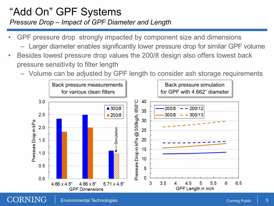
• GPF pressure drop strongly impacted by component size and dimensions – Larger diameter enables significantly lower pressure drop for similar GPF volume
• Besides lowest pressure drop values the 200/8 design also offers lowest back pressure sensitivity to filter length – Volume can be adjusted by GPF length to consider ash storage requirements
Back pressure simulation for GPF with 4.662” diameter
“Add On” GPF Systems Pressure Drop – Impact of GPF Diameter and Length
Back pressure measurements for various clean filters
Sim
ulat
ion
6 Environmental Technologies Corning Public
“Add On” GPF Systems Filtration Efficiency for 200/8 GPF Design
• Filtration efficiency requirements expected to be in the range of 50 to 90% – Assuming engine out emissions of 8 to 20 x 1011#/km and targeted tailpipe
emissions below 6 x 10¹¹#/km • 200/8 design with an optimized microstructure having a porosity in the medium
range offers filtration efficiencies in the required target range
• Similar to diesel applications, the accumulation and uncontrolled oxidation of soot is expected to lead to high GPF temperatures and therefore high thermal stress – Typical soot load expectations for GPF around 2 to 3g/l
• Lab reactor study on thermal response for GPF during simulated fuel cut engine operation – simulation of oxygen supply during gasoline engine operation
0
5
10
15
20
25
30
35
40
200
300
400
500
600
700
800
900
1000
1100
500 550 600 650 700 750 800
O2
[%],
Mas
s Fl
ow [k
g/h]
Tem
pera
ture
[°C
]
Time [s]
127mm 76mm
25mm
Flow
O2 (downstream)
GPF 200/8 - 50% (bare)2g/l soot, 700°C
Mass Flow
Lab scale fuel cut experiment Uncoated GPF in 200/8 design with 50% porosity Inlet temperature 700°C Oxygen pulse 40s
Flow
8 Environmental Technologies Corning Public
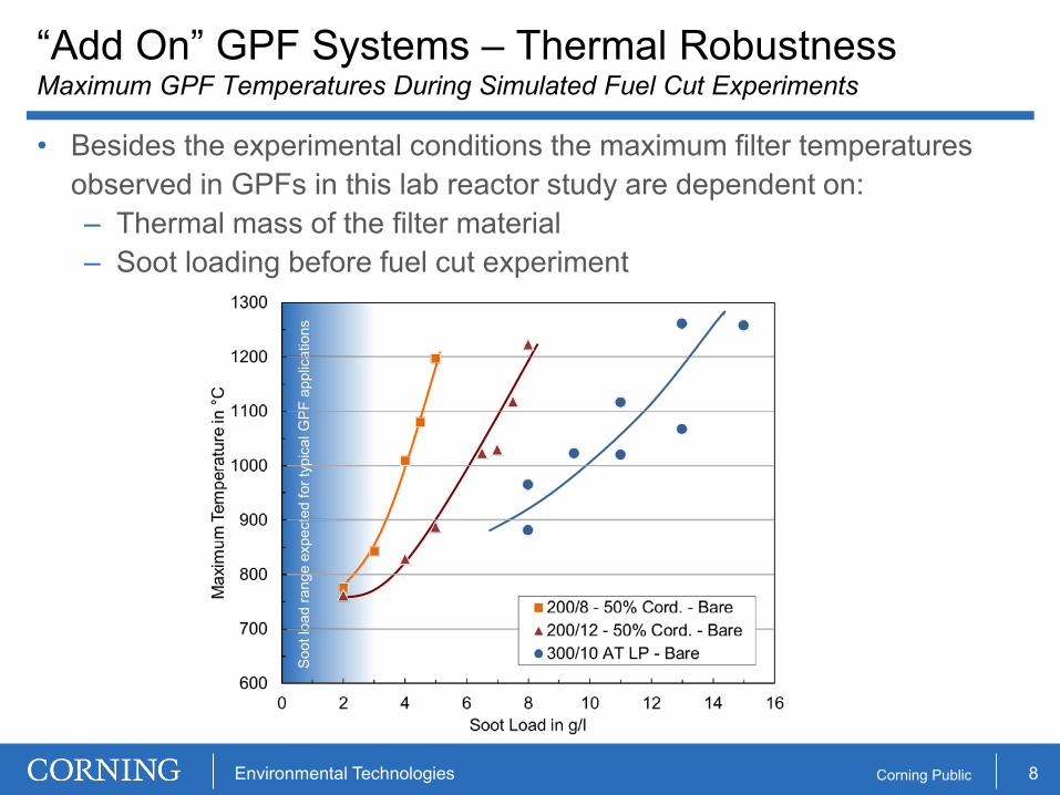
“Add On” GPF Systems – Thermal Robustness Maximum GPF Temperatures During Simulated Fuel Cut Experiments
• Besides the experimental conditions the maximum filter temperatures observed in GPFs in this lab reactor study are dependent on: – Thermal mass of the filter material – Soot loading before fuel cut experiment
So
ot lo
ad ra
nge
expe
cted
for t
ypic
al G
PF a
pplic
atio
ns
9 Environmental Technologies Corning Public
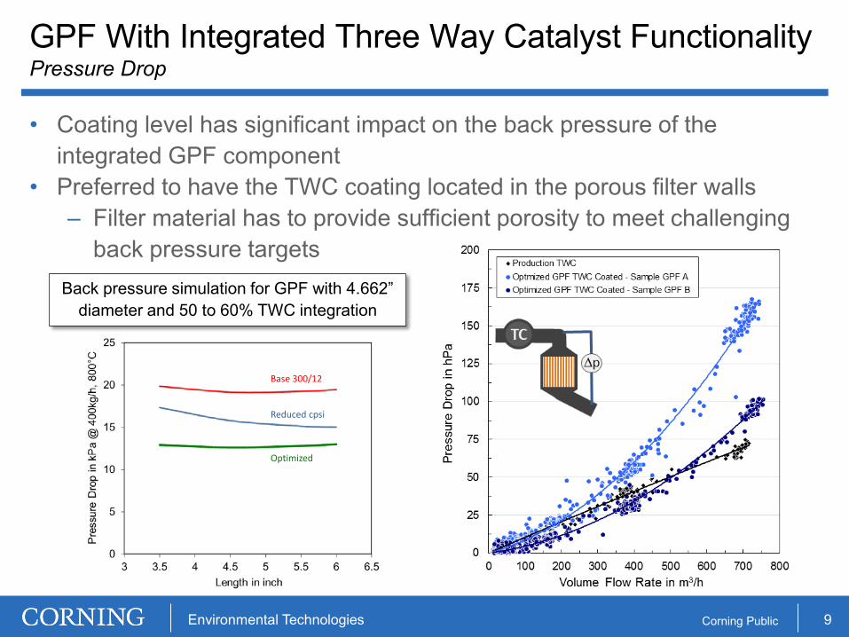
• Coating level has significant impact on the back pressure of the integrated GPF component
• Preferred to have the TWC coating located in the porous filter walls – Filter material has to provide sufficient porosity to meet challenging
back pressure targets
GPF With Integrated Three Way Catalyst Functionality Pressure Drop
Base 300/12
Reduced cpsi
Optimized
Back pressure simulation for GPF with 4.662” diameter and 50 to 60% TWC integration
10 Environmental Technologies Corning Public
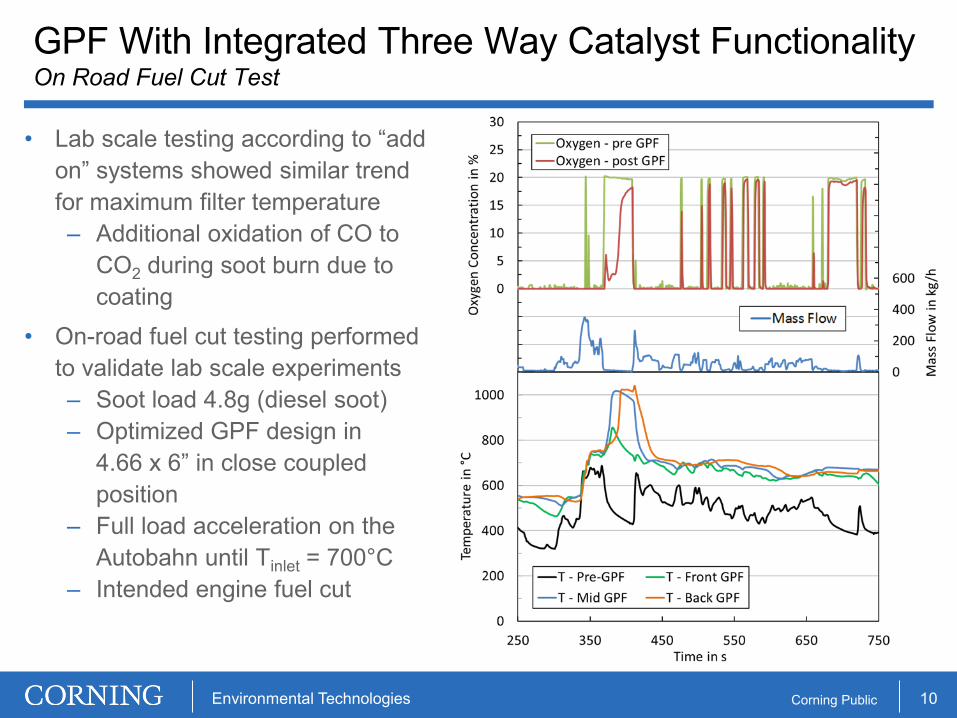
• Lab scale testing according to “add on” systems showed similar trend for maximum filter temperature – Additional oxidation of CO to
CO2 during soot burn due to coating
• On-road fuel cut testing performed to validate lab scale experiments – Soot load 4.8g (diesel soot) – Optimized GPF design in
4.66 x 6” in close coupled position
– Full load acceleration on the Autobahn until Tinlet = 700°C
– Intended engine fuel cut
GPF With Integrated Three Way Catalyst Functionality On Road Fuel Cut Test
11 Environmental Technologies Corning Public
• Continuing efforts for further CO2 and PN reduction create a challenging environment for vehicles equipped with DI gasoline engines
• Gasoline particulate filters will be an enabler to meet these challenging targets either as an alternative or as a supplement to improved combustion recipes
• Gasoline particulate filters can be designed: – As an “add on” solution to an existing after treatment system – As a gasoline particulate filter with integrated three way catalyst
functionality • Optimized designs for gasoline particulate filter applications
Summary Advanced Particulate Filter Technologies for DI Gasoline Engine Applications
"Add on" GPF TWC Integrated GPFCell Density 200cpsi 200/300cpsi