PNNL-21174 Prepared for the U.S. Department of Energy under Contract DE-AC05-76RL01830 Advanced Redox Flow Batteries for Stationary Electrical Energy Storage L Li W Wang S Kim Z Yang G Xai March 2012
Transcript
PNNL-21174
Prepared for the U.S. Department of Energy under Contract DE-AC05-76RL01830
Advanced Redox Flow Batteries for Stationary Electrical Energy Storage L Li W Wang S Kim Z Yang G Xai March 2012
DISCLAIMER This report was prepared as an account of work sponsored by an agency of the United States Government. Neither the United States Government nor any agency thereof, nor Battelle Memorial Institute, nor any of their employees, makes any warranty, express or implied, or assumes any legal liability or responsibility for the accuracy, completeness, or usefulness of any information, apparatus, product, or process disclosed, or represents that its use would not infringe privately owned rights. Reference herein to any specific commercial product, process, or service by trade name, trademark, manufacturer, or otherwise does not necessarily constitute or imply its endorsement, recommendation, or favoring by the United States Government or any agency thereof, or Battelle Memorial Institute. The views and opinions of authors expressed herein do not necessarily state or reflect those of the United States Government or any agency thereof. PACIFIC NORTHWEST NATIONAL LABORATORY operated by BATTELLE for the UNITED STATES DEPARTMENT OF ENERGY under Contract DE-AC05-76RL01830 Printed in the United States of America Available to DOE and DOE contractors from the Office of Scientific and Technical Information,
email: [email protected] Available to the public from the National Technical Information Service, U.S. Department of Commerce, 5285 Port Royal Rd., Springfield, VA 22161
PNNL REPORT PNNL-21174 Unlimited Release Printed February 2012
Advanced Redox Flow Batteries for Stationary Electrical Energy Storage Milestone Report for the DOE-OE Energy Storage Systems Program (FY12 Quarter 1: October 2011 through December 2011) Liyu Li, Soowhan Kim, Gordon Xia, Wei Wang, Z. Gary Yang Prepared by Pacific Northwest National Laboratory Richland, Washington 99354 Pacific Northwest National Laboratory is a multi-program laboratory managed and operated by Battelle Memorial Institute for the U.S. Department of Energy under contract DE-AC05-76RL01830. Approved for public release; further dissemination unlimited. Issued by Pacific Northwest National Laboratory, operated for the United States Department of Energy by Battelle Memorial Institute. NOTICE: This report was prepared as an account of work sponsored by an agency of the United States Government. Neither the United States Government, nor any agency thereof, nor any of their employees, nor any of their contractors, subcontractors, or their employees, make any warranty, express or implied, or assume any legal liability or responsibility for the accuracy, completeness, or usefulness of any information, apparatus, product, or process disclosed, or represent that its use would not infringe privately owned rights. Reference herein to any specific commercial product, process, or service by trade name, trademark, manufacturer, or otherwise, does not necessarily constitute or imply its endorsement, recommendation, or favoring by the United States Government, any agency thereof, or any of their contractors or subcontractors. The views and opinions expressed herein do not necessarily state or reflect those of the United States Government, any agency thereof, or any of their contractors.
2
PNNL-21174
Unlimited Release Printed February 2012
Advanced Redox Flow Batteries for Stationary Electrical Energy Storage
Milestone Report for the DOE Energy Storage Systems Program (FY12 Quarter 1: October 2011 through December 2011)
Liyu Li, Soowhan Kim, Gordon Xia, Z. Gary Yang
Energy and Environmental Directorate Pacific Northwest National Laboratory
Richland, WA 99354
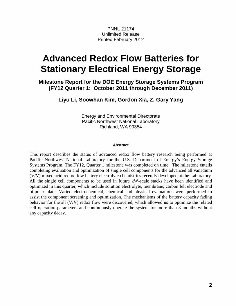
Abstract This report describes the status of advanced redox flow battery research being performed at Pacific Northwest National Laboratory for the U.S. Department of Energy’s Energy Storage Systems Program. The FY12, Quarter 1 milestone was completed on time. The milestone entails completing evaluation and optimization of single cell components for the advanced all vanadium (V/V) mixed acid redox flow battery electrolyte chemistries recently developed at the Laboratory. All the single cell components to be used in future kW-scale stacks have been identified and optimized in this quarter, which include solution electrolyte, membrane; carbon felt electrode and bi-polar plate. Varied electrochemical, chemical and physical evaluations were performed to assist the component screening and optimization. The mechanisms of the battery capacity fading behavior for the all (V/V) redox flow were discovered, which allowed us to optimize the related cell operation parameters and continuously operate the system for more than 3 months without any capacity decay.
3
Project Description Concerns over the environmental consequences of burning fossil fuels and their resource constraints, along with the growing world demands in energy, have led to increasing penetration of renewable energy generated from sources such as solar and wind. However, the intermittent and varied nature of the renewable resources makes integration and dispatch of the renewable power challenging. A solution to this problem is to employ electrical energy storage (EES), which is widely considered as an effective approach to improve the grid reliability, power quality, and economy of the renewable energy.[1-3] Among the most promising EES technologies are the redox flow batteries (RFBs). RFB is an electrochemical device that is capable of storing up to multi-megawatt-hours (MWhs) of electrical energy via a reversible electrochemical energy conversion.[4,5]
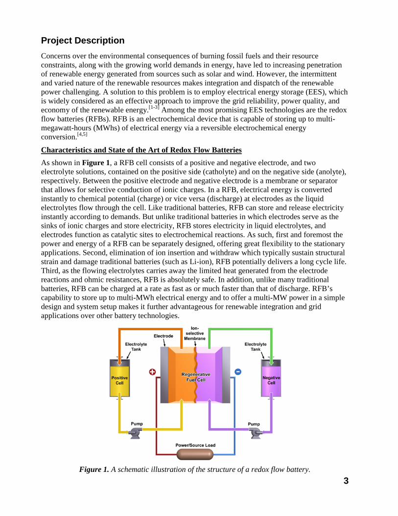
Characteristics and State of the Art of Redox Flow Batteries As shown in Figure 1, a RFB cell consists of a positive and negative electrode, and two electrolyte solutions, contained on the positive side (catholyte) and on the negative side (anolyte), respectively. Between the positive electrode and negative electrode is a membrane or separator that allows for selective conduction of ionic charges. In a RFB, electrical energy is converted instantly to chemical potential (charge) or vice versa (discharge) at electrodes as the liquid electrolytes flow through the cell. Like traditional batteries, RFB can store and release electricity instantly according to demands. But unlike traditional batteries in which electrodes serve as the sinks of ionic charges and store electricity, RFB stores electricity in liquid electrolytes, and electrodes function as catalytic sites to electrochemical reactions. As such, first and foremost the power and energy of a RFB can be separately designed, offering great flexibility to the stationary applications. Second, elimination of ion insertion and withdraw which typically sustain structural strain and damage traditional batteries (such as Li-ion), RFB potentially delivers a long cycle life. Third, as the flowing electrolytes carries away the limited heat generated from the electrode reactions and ohmic resistances, RFB is absolutely safe. In addition, unlike many traditional batteries, RFB can be charged at a rate as fast as or much faster than that of discharge. RFB’s capability to store up to multi-MWh electrical energy and to offer a multi-MW power in a simple design and system setup makes it further advantageous for renewable integration and grid applications over other battery technologies.
Figure 1. A schematic illustration of the structure of a redox flow battery.
4
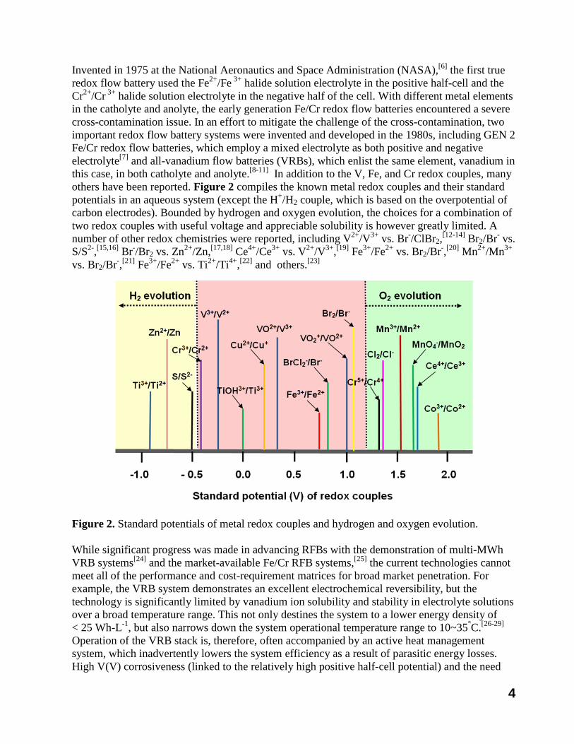
Invented in 1975 at the National Aeronautics and Space Administration (NASA),[6] the first true redox flow battery used the Fe2+/Fe 3+ halide solution electrolyte in the positive half-cell and the Cr2+/Cr 3+ halide solution electrolyte in the negative half of the cell. With different metal elements in the catholyte and anolyte, the early generation Fe/Cr redox flow batteries encountered a severe cross-contamination issue. In an effort to mitigate the challenge of the cross-contamination, two important redox flow battery systems were invented and developed in the 1980s, including GEN 2 Fe/Cr redox flow batteries, which employ a mixed electrolyte as both positive and negative electrolyte[7] and all-vanadium flow batteries (VRBs), which enlist the same element, vanadium in this case, in both catholyte and anolyte.[8-11] In addition to the V, Fe, and Cr redox couples, many others have been reported. Figure 2 compiles the known metal redox couples and their standard potentials in an aqueous system (except the H+/H2 couple, which is based on the overpotential of carbon electrodes). Bounded by hydrogen and oxygen evolution, the choices for a combination of two redox couples with useful voltage and appreciable solubility is however greatly limited. A number of other redox chemistries were reported, including V2+/V3+ vs. Br-/ClBr2,[12-14] Br2/Br- vs. S/S2-,[15,16] Br-/Br2 vs. Zn2+/Zn,[17,18] Ce4+/Ce3+ vs. V2+/V3+,[19] Fe3+/Fe2+ vs. Br2/Br-,[20] Mn2+/Mn3+
vs. Br2/Br-,[21] Fe3+/Fe2+ vs. Ti2+/Ti4+,[22] and others.[23]
Figure 2. Standard potentials of metal redox couples and hydrogen and oxygen evolution.
While significant progress was made in advancing RFBs with the demonstration of multi-MWh VRB systems[24] and the market-available Fe/Cr RFB systems,[25] the current technologies cannot meet all of the performance and cost-requirement matrices for broad market penetration. For example, the VRB system demonstrates an excellent electrochemical reversibility, but the technology is significantly limited by vanadium ion solubility and stability in electrolyte solutions over a broad temperature range. This not only destines the system to a lower energy density of < 25 Wh-L-1, but also narrows down the system operational temperature range to 10~35°C.[26-29] Operation of the VRB stack is, therefore, often accompanied by an active heat management system, which inadvertently lowers the system efficiency as a result of parasitic energy losses. High V(V) corrosiveness (linked to the relatively high positive half-cell potential) and the need
5
for relatively high-cost membranes are other issues that have plagued the VRB system to date. In comparison, the Fe-Cr flow battery uses relatively low-cost elements, yet its Cr2+/Cr3+ redox couple demonstrates an inferior electrochemical activity that requires a combination of elevated operation temperature (at > 40 °C) and a catalyst-loaded electrode to enhance its redox reaction. Besides, the Fe-Cr system also involves hydrogen gas evolution and is thus complicated by gas management issues, limiting fuel use (~60%) while lowering the coulombic efficiency[30].
New Discoveries at PNNL Researchers at PNNL have recently revisited the solution chemistry of the vanadium electrolytes. It was found that the <1.7M concentration limit of the vanadium sulfate electrolyte is a compromise between the low solubility of VOSO4 at low temperatures and the precipitation of V2O5 at higher temperature[31]. With advanced nuclear magnetic resonance (NMR) spectroscopy and density functional theory (DFT) based computational modeling, the structure and kinetics of vanadium (IV) [32] and vanadium (V) [33] species were further investigated. The scientific study revealed that the vanadium (IV) species in a hydrated vanadyl ion ([VO(H2O)5]2+) form an octahedral coordination with vanadyl oxygen in the axial position, with the remaining positions occupied by water molecules. An increase in the sulfate acid concentration would lead to an increase of sulfate anion in the second-coordination sphere of the vanadyl ion, resulting in an increase in re-orientation activation energy for the vanadyl ion. As such, the VOSO4 solubility decreases with increasing sulfate acid concentration[34]. On the other hand, the vanadium (V) species was identified as a hydrated penta co-ordinated vanadate ion [VO2(H2O3)]1+, which is not stable at elevated temperature and changes into neutral H3VO4 molecules via a deprotonation process, subsequently leading to an irreversible precipitation of the solid V2O5 phase.
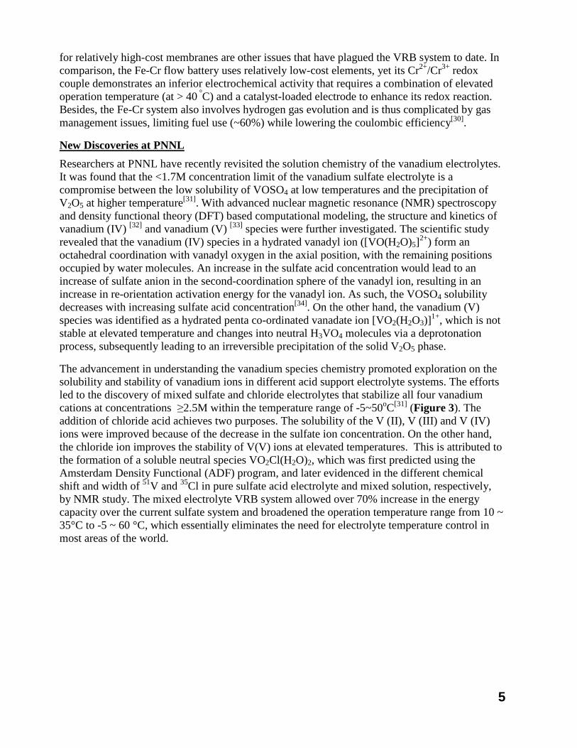
The advancement in understanding the vanadium species chemistry promoted exploration on the solubility and stability of vanadium ions in different acid support electrolyte systems. The efforts led to the discovery of mixed sulfate and chloride electrolytes that stabilize all four vanadium cations at concentrations ≥2.5M within the temperature range of -5~50oC[31] (Figure 3). The addition of chloride acid achieves two purposes. The solubility of the V (II), V (III) and V (IV) ions were improved because of the decrease in the sulfate ion concentration. On the other hand, the chloride ion improves the stability of V(V) ions at elevated temperatures. This is attributed to the formation of a soluble neutral species VO2Cl(H2O)2, which was first predicted using the Amsterdam Density Functional (ADF) program, and later evidenced in the different chemical shift and width of 51V and 35Cl in pure sulfate acid electrolyte and mixed solution, respectively, by NMR study. The mixed electrolyte VRB system allowed over 70% increase in the energy capacity over the current sulfate system and broadened the operation temperature range from 10 ~ 35°C to -5 ~ 60 °C, which essentially eliminates the need for electrolyte temperature control in most areas of the world.
6
Figure 3. A schematic illustration of a vanadium redox flow battery (discharging) using mixed sulfate-chloride electrolyte solutions at temperatures higher than 20oC.
Cathode: VO2+ + Cl- + H2O – e
VO2Cl + 2H+
(1)
Anode: V3+ + e
V2+ (2)
Cell: VO2+ + Cl- + H2O + V3+
VO2Cl + 2H+ + V2+
(3)
Scope and Milestones in FY12
The overall objective of this project is to develop and demonstrate low cost all vanadium mixed acid flow battery technologies using the PNNL invented electrolytes. Toward this goal, we focus on screening and optimization of cell and stack components, including electrolytes, carbon felt electrodes, current-collecting bi-polar plates, and proton membrane or separator. These components are then prepared at immediate scale and assembled into stacks to further validate the electrolytes, other components and designs. A bench-top system up to an 1- kW stack and 1-kWh tanks will be demonstrated at the end of FY12. To help optimize stack design and system integration, computer modeling is performed to simulate flow and electrical field, and to shunt current (a parasitic current that can cause a significant energy loss and affect the reliability and durability of the stacks).
To achieve the overall goal in FY12, the following milestones are planned:
First Quarter - Complete evaluation and optimization of cell components. The related components will be used in the 1-kW prototype design and assembly. This milestone has been completed. Second Quarter - Complete cell/stack designs and scale up for the 1-kW prototype
Third Quarter - Complete assembling a 1-kW/1-kWh prototype system
Charge Discharge
Charge Discharge
Charge Discharge
7
Fourth Quarter - Evaluate the prototype system and report its early stage performance with power cost <$2240/kW and energy cost <$560/kW-hr for a 4-hr system
Beyond FY12, we aim to achieve the following targets in cost reduction in the next 5 years, via cooperation with industries and universities:
• FY12: power cost <$2240/kW and energy cost <$560/kW-hr for a 4-hr system
• FY13: power cost <$1900/kW and energy cost <$475/kW-hr for a 4-hr system
• FY14: power cost <$1600/kW and energy cost <$400/kW-hr for a 4-hr system
• FY15: power cost <$1300/kW and energy cost <$325/kW-hr for a 4-hr system
• FY16: power cost <$1200/kW and energy cost <$300/kW-hr for a 4-hr system
8
FY12 Quarter 1 Project Status Summary The first quarter milestone is to “complete evaluation and optimization of cell components for a 1-kW prototype design and assembly”. This milestone was successfully completed in December 2011.
During the first quarter, we were focusing on optimizing the electrolyte composition for the all vanadium mixed acid system in terms of (1) detailed study of the electrolyte temperature stability and ; (2) elaboration of the V ion transport mechanism, which leads to the mechanistic understanding on the capacity loss over cycling, a serious issue encountered during the redox flow battery operation. The knowledge obtained from the study helps solve the capacity fading and energy loss issue. A stable operation with negligible capacity loss was achieved. Operation parameters were also defined.
1. Optimization of electrolyte compositions 1.1 All Vanadium Mixed Acid System
The stability tests of the all vanadium mixed acid system under different temperatures and varied compositions have been investigated systematically with ex-situ heating/cooling treatment and in-situ flow battery testing methods. The temperatures, ranging from -15 to 40oC, were maintained during the tests in a temperature-controlled bath. All the stability tests were performed statically without any stirring or shaking. During the test, each sample was checked visually once per day for precipitation and solution color change. It was found that the vanadium-sulfate-chloride system was stable up to 2.5M and beyond that, vanadium (III) precipitated from the electrolyte solution when temperatures were lower than -5oC. Although this precipitate could be re-dissolved simply by heating the precursor solution to an elevated temperature, it seriously affected the vanadium redox battery performance. Studies were then carried out to understand the chemistry behind the thermal stability behavior of V3+ cation in the mixed acid electrolyte to help optimize the electrolytes. First we performed density functional theory (DFT) based calculations that were verified by electronic and nuclear magnetic resonance (NMR) spectroscopic measurements. The powerful combination of theory and experimental measurements successfully helped us derive the molecular structure of V (V) cations in mixed acid based electrolyte solutions and led us discovering the new vanadium mixed acid system. Figure 4 shows pristine hexaaqua V3+ cation and the counter anion (sulfate /chloride ions) complexed V(III) species with respective bond lengths calculated from our DFT study. The electronic spectra by UV-Vis spectroscopy were then obtained to verify the anion complexed structures in the V3+ redox battery electrolytes. Figure 6 (a) shows the room temperature optical absorption spectrum of V3+ with various vanadium concentrations. The electronic spectra of V3+ in electrolyte solution reveals broad absorption bands representing 3T1g
→ 3T2g (500-700 nm) and 3T1g → 3T1g (300-450 nm). These absorption maxima were comparable with the electronic spectra of single crystals containing [V3+6(H2O)]3+ cation, which has a maxima at 578 nm and 395 nm for 3T2g and 3T1g absorption bands, respectively. For the electrolyte solutions, both the 3T1g band (405 nm) and the 3T2g band (610 nm) are shifted towards higher wavelengths compared with [V3+6(H2O)]3+ cation. The 3T1g band shifting towards higher wavelength might indicate the presence of V3+ dimer species and/or chlorine complexed V3+ cation, both are reportedly have characteristics absorption around 430
9
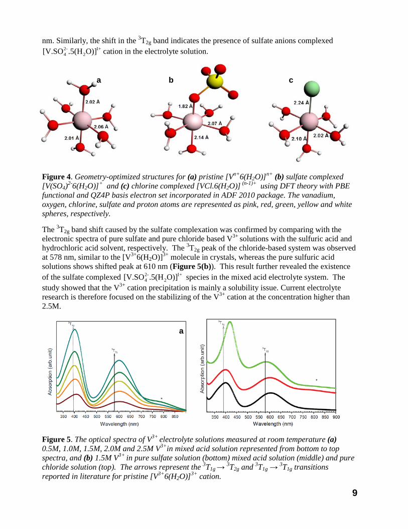
nm. Similarly, the shift in the 3T2g band indicates the presence of sulfate anions complexed cation in the electrolyte solution.
Figure 4. Geometry-optimized structures for (a) pristine [Vn+6(H2O)]n+ (b) sulfate complexed [V(SO4)2-6(H2O)]+ and (c) chlorine complexed [VCl.6(H2O)] (n-1)+ using DFT theory with PBE functional and QZ4P basis electron set incorporated in ADF 2010 package. The vanadium, oxygen, chlorine, sulfate and proton atoms are represented as pink, red, green, yellow and white spheres, respectively.
The 3T2g band shift caused by the sulfate complexation was confirmed by comparing with the electronic spectra of pure sulfate and pure chloride based V3+ solutions with the sulfuric acid and hydrochloric acid solvent, respectively. The 3T2g peak of the chloride-based system was observed at 578 nm, similar to the [V3+6(H2O)]3+ molecule in crystals, whereas the pure sulfuric acid solutions shows shifted peak at 610 nm (Figure 5(b)). This result further revealed the existence of the sulfate complexed species in the mixed acid electrolyte system. The study showed that the V3+ cation precipitation is mainly a solubility issue. Current electrolyte research is therefore focused on the stabilizing of the V3+ cation at the concentration higher than 2.5M.
Figure 5. The optical spectra of V3+ electrolyte solutions measured at room temperature (a) 0.5M, 1.0M, 1.5M, 2.0M and 2.5M V3+in mixed acid solution represented from bottom to top spectra, and (b) 1.5M V3+ in pure sulfate solution (bottom) mixed acid solution (middle) and pure chloride solution (top). The arrows represent the 3T1g
→ 3T2g and 3T1g → 3T1g transitions reported in literature for pristine [V3+6(H2O)]3+ cation.
+12
-24 O)].5(H[V.SO
+12
-24 O)].5(H[V.SO
a
a b c
10
2. Membrane development for V/V system System
The ion exchange membrane is one of the most important components in the RFB system; it prevents the crossover of the active materials in the positive and negative electrolyte while allowing proton transport to complete the circuit. Perflourinated polymers such as Nafion (Dupont) have been often used in the VRB system because of their excellent chemical stability in the highly oxidative V5+ environment and high proton conductivity. The high price of the Nafion membrane, however, accounts for over 40% of the cell stack cost[24]. As such, search for low-cost substitutes has been a major effort in advancing the redox flow batteries. Several lower-cost non-perfluorinated polymer membranes were evaluated by others for the VRBs. So far there has been no low-cost alternative that can match the Nafion membranes in terms of conductivity, selectivity and chemical stability.[35,36] In the first quarter, PNNL extensively explored the replacement of the expensive perfluorinated Nafion® ion exchange membrane by low-cost hydrocarbon-based membrane. we have previously developed a sulfonated poly(arylene ether) membrane (S-Radel) having one order of magnitude lower permeability of VO2+ than Nafion 117, which resulted in higher coulombic efficiency and lower capacity loss per cycle.19 However, the cell performance declined rapidly after 40 cycles due to physical and/or chemical degradation by VO2
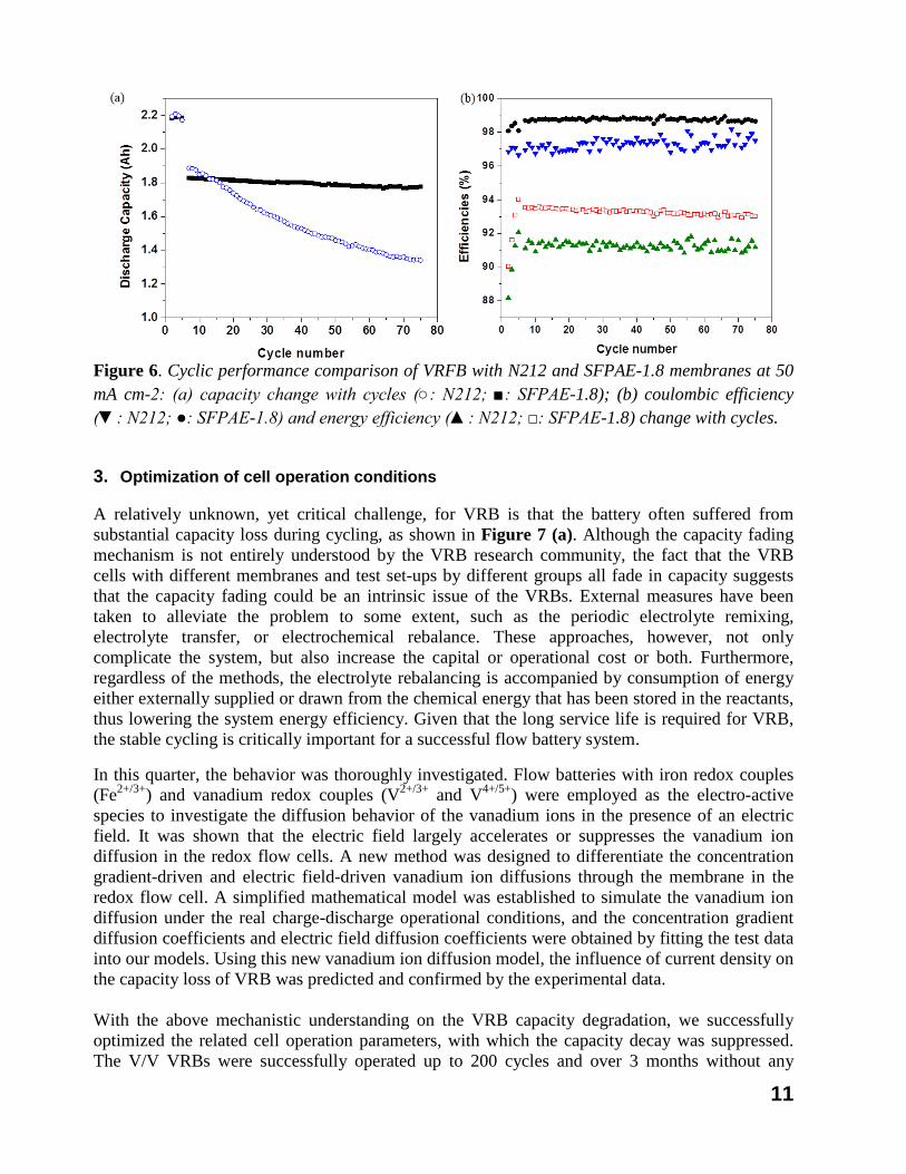
+.36 In a continuous collaboration with the membrane team at the Pennsylvania State University, University Park, PA, we developed partially fluorinated sulfonated poly(arylene ether) (SFPAE) copolymers with a range of ion exchange capacities (IECs) as chemically stable proton exchange membranes for vanadium redox flow battery (VRFB) applications. Fluorinated poly(arylene ether)s (FPAE) were successfully synthesized by reacting decafluorobiphenyl and biphenol A at room temperature for 24h. The influence of IEC on membrane water uptake, mechanical properties, thermal and oxidative stability, proton conductivity, and VO2+ permeability was studied. Improved stability was observed for SFPAEs as compared to non-fluorinated samples. SFPAE-1.8 with optimized proton conductivity to vanadium permeability selectivity was selected for evaluation in VRFB and compared to the performance of a cell with NAFION® N212 membrane. VRFB with SFPAE-1.8 membrane had higher coulombic efficiencies, voltage efficiencies and energy efficiencies than VRFB with N212 membrane under all tested current densities. The capacity fade of VRFB with SFPAE-1.8 membrane was 1.1 mAh per cycle, which was about 7 times lower than the fade experienced in a VRFB with an N212 membrane. The cycling performance comparison of VRB with N212 and membranes at 50mA/cm2 are provided at Figure 6. From a cost effective of view, SFPAE-1.8 is about 30% of the cost of the NAFION® N212. This work demonstrates our progress towards high-performance, low-cost, long-lifetime ion exchange membranes for electrochemical energy storage devices.
11
Figure 6. Cyclic performance comparison of VRFB with N212 and SFPAE-1.8 membranes at 50 mA cm-2: (a) capacity change with cycles (○: N212; ■: SFPAE-1.8); (b) coulombic efficiency (▼: N212; ●: SFPAE-1.8) and energy efficiency (▲: N212; □: SFPAE-1.8) change with cycles.
3. Optimization of cell operation conditions
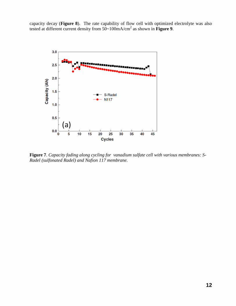
A relatively unknown, yet critical challenge, for VRB is that the battery often suffered from substantial capacity loss during cycling, as shown in Figure 7 (a). Although the capacity fading mechanism is not entirely understood by the VRB research community, the fact that the VRB cells with different membranes and test set-ups by different groups all fade in capacity suggests that the capacity fading could be an intrinsic issue of the VRBs. External measures have been taken to alleviate the problem to some extent, such as the periodic electrolyte remixing, electrolyte transfer, or electrochemical rebalance. These approaches, however, not only complicate the system, but also increase the capital or operational cost or both. Furthermore, regardless of the methods, the electrolyte rebalancing is accompanied by consumption of energy either externally supplied or drawn from the chemical energy that has been stored in the reactants, thus lowering the system energy efficiency. Given that the long service life is required for VRB, the stable cycling is critically important for a successful flow battery system.
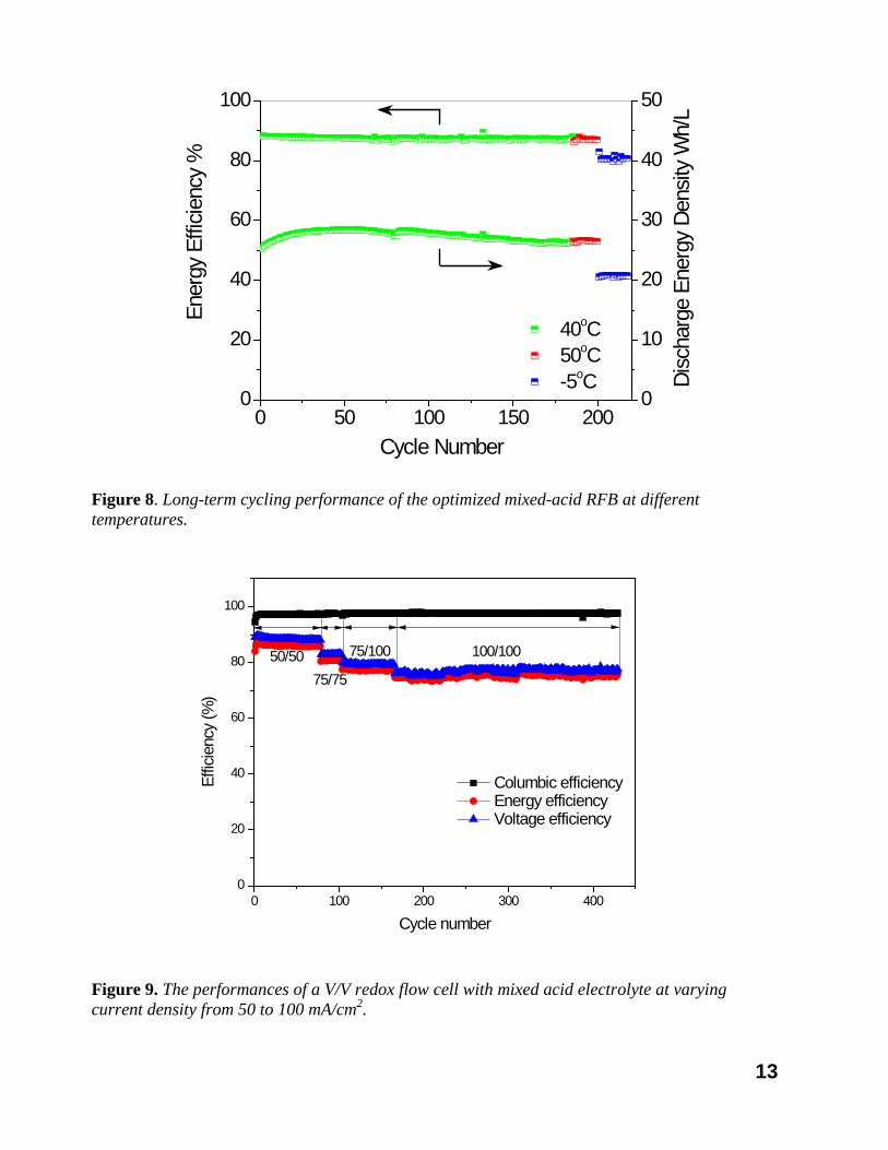
In this quarter, the behavior was thoroughly investigated. Flow batteries with iron redox couples (Fe2+/3+) and vanadium redox couples (V2+/3+ and V4+/5+) were employed as the electro-active species to investigate the diffusion behavior of the vanadium ions in the presence of an electric field. It was shown that the electric field largely accelerates or suppresses the vanadium ion diffusion in the redox flow cells. A new method was designed to differentiate the concentration gradient-driven and electric field-driven vanadium ion diffusions through the membrane in the redox flow cell. A simplified mathematical model was established to simulate the vanadium ion diffusion under the real charge-discharge operational conditions, and the concentration gradient diffusion coefficients and electric field diffusion coefficients were obtained by fitting the test data into our models. Using this new vanadium ion diffusion model, the influence of current density on the capacity loss of VRB was predicted and confirmed by the experimental data. With the above mechanistic understanding on the VRB capacity degradation, we successfully optimized the related cell operation parameters, with which the capacity decay was suppressed. The V/V VRBs were successfully operated up to 200 cycles and over 3 months without any
12
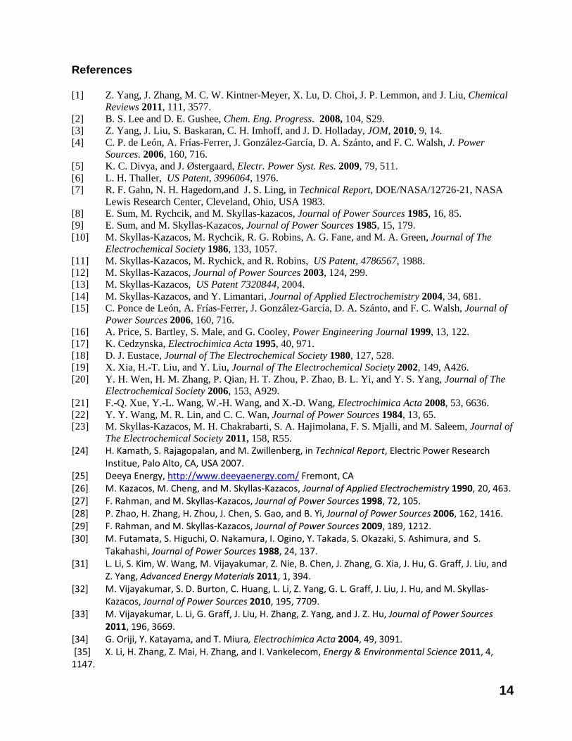
capacity decay (Figure 8). The rate capability of flow cell with optimized electrolyte was also tested at different current density from 50~100mA/cm2 as shown in Figure 9.
Figure 7. Capacity fading along cycling for vanadium sulfate cell with various membranes: S-Radel (sulfonated Radel) and Nafion 117 membrane.
13
0 50 100 150 2000
20
40
60
80
100
Cycle Number
Ener
gy E
fficie
ncy
%
Disc
harg
e En
ergy
Den
sity
Wh/
L
0
10
20
30
40
50
40oC 50oC -5oC
Figure 8. Long-term cycling performance of the optimized mixed-acid RFB at different temperatures.
0 100 200 300 4000
20
40
60
80
100
Effic
ienc
y (%
)
Cycle number
Columbic efficiency Energy efficiency Voltage efficiency
50/5075/75
75/100 100/100
Figure 9. The performances of a V/V redox flow cell with mixed acid electrolyte at varying current density from 50 to 100 mA/cm2.
14
References [1] Z. Yang, J. Zhang, M. C. W. Kintner-Meyer, X. Lu, D. Choi, J. P. Lemmon, and J. Liu, Chemical
Reviews 2011, 111, 3577. [2] B. S. Lee and D. E. Gushee, Chem. Eng. Progress. 2008, 104, S29. [3] Z. Yang, J. Liu, S. Baskaran, C. H. Imhoff, and J. D. Holladay, JOM, 2010, 9, 14. [4] C. P. de León, A. Frías-Ferrer, J. González-García, D. A. Szánto, and F. C. Walsh, J. Power
Sources. 2006, 160, 716. [5] K. C. Divya, and J. Østergaard, Electr. Power Syst. Res. 2009, 79, 511. [6] L. H. Thaller, US Patent, 3996064, 1976. [7] R. F. Gahn, N. H. Hagedorn,and J. S. Ling, in Technical Report, DOE/NASA/12726-21, NASA
Lewis Research Center, Cleveland, Ohio, USA 1983. [8] E. Sum, M. Rychcik, and M. Skyllas-kazacos, Journal of Power Sources 1985, 16, 85. [9] E. Sum, and M. Skyllas-Kazacos, Journal of Power Sources 1985, 15, 179. [10] M. Skyllas-Kazacos, M. Rychcik, R. G. Robins, A. G. Fane, and M. A. Green, Journal of The
Electrochemical Society 1986, 133, 1057. [11] M. Skyllas-Kazacos, M. Rychick, and R. Robins, US Patent, 4786567, 1988. [12] M. Skyllas-Kazacos, Journal of Power Sources 2003, 124, 299. [13] M. Skyllas-Kazacos, US Patent 7320844, 2004. [14] M. Skyllas-Kazacos, and Y. Limantari, Journal of Applied Electrochemistry 2004, 34, 681. [15] C. Ponce de León, A. Frías-Ferrer, J. González-García, D. A. Szánto, and F. C. Walsh, Journal of
Power Sources 2006, 160, 716. [16] A. Price, S. Bartley, S. Male, and G. Cooley, Power Engineering Journal 1999, 13, 122. [17] K. Cedzynska, Electrochimica Acta 1995, 40, 971. [18] D. J. Eustace, Journal of The Electrochemical Society 1980, 127, 528. [19] X. Xia, H.-T. Liu, and Y. Liu, Journal of The Electrochemical Society 2002, 149, A426. [20] Y. H. Wen, H. M. Zhang, P. Qian, H. T. Zhou, P. Zhao, B. L. Yi, and Y. S. Yang, Journal of The
Electrochemical Society 2006, 153, A929. [21] F.-Q. Xue, Y.-L. Wang, W.-H. Wang, and X.-D. Wang, Electrochimica Acta 2008, 53, 6636. [22] Y. Y. Wang, M. R. Lin, and C. C. Wan, Journal of Power Sources 1984, 13, 65. [23] M. Skyllas-Kazacos, M. H. Chakrabarti, S. A. Hajimolana, F. S. Mjalli, and M. Saleem, Journal of
The Electrochemical Society 2011, 158, R55. [24] H. Kamath, S. Rajagopalan, and M. Zwillenberg, in Technical Report, Electric Power Research
Institue, Palo Alto, CA, USA 2007. [25] Deeya Energy, http://www.deeyaenergy.com/ Fremont, CA [26] M. Kazacos, M. Cheng, and M. Skyllas-Kazacos, Journal of Applied Electrochemistry 1990, 20, 463. [27] F. Rahman, and M. Skyllas-Kazacos, Journal of Power Sources 1998, 72, 105. [28] P. Zhao, H. Zhang, H. Zhou, J. Chen, S. Gao, and B. Yi, Journal of Power Sources 2006, 162, 1416. [29] F. Rahman, and M. Skyllas-Kazacos, Journal of Power Sources 2009, 189, 1212. [30] M. Futamata, S. Higuchi, O. Nakamura, I. Ogino, Y. Takada, S. Okazaki, S. Ashimura, and S.
Takahashi, Journal of Power Sources 1988, 24, 137. [31] L. Li, S. Kim, W. Wang, M. Vijayakumar, Z. Nie, B. Chen, J. Zhang, G. Xia, J. Hu, G. Graff, J. Liu, and
Z. Yang, Advanced Energy Materials 2011, 1, 394. [32] M. Vijayakumar, S. D. Burton, C. Huang, L. Li, Z. Yang, G. L. Graff, J. Liu, J. Hu, and M. Skyllas-
Kazacos, Journal of Power Sources 2010, 195, 7709. [33] M. Vijayakumar, L. Li, G. Graff, J. Liu, H. Zhang, Z. Yang, and J. Z. Hu, Journal of Power Sources
2011, 196, 3669. [34] G. Oriji, Y. Katayama, and T. Miura, Electrochimica Acta 2004, 49, 3091. [35] X. Li, H. Zhang, Z. Mai, H. Zhang, and I. Vankelecom, Energy & Environmental Science 2011, 4, 1147.