Advanced 3R regenerator scheme for high spectral efficient signal waveforms M. Sorokina, S. Sygletos, F. Ferreira, A. Perentos, A. Ellis and S. Turitsyn Aston Institute of Photonic Technologies, Aston University, Birmingham, UK [email protected]ABSTRACT We propose a novel 3R regenerator architecture for highly spectral efficient signals. Through numerical simulations we evaluate its performance and compare with traditional 2R schemes. The results of the analysis demonstrate necessity of 3R for regeneration of NRZ pulses and its relevance for future high capacity transmission systems. Keywords: all-optical regeneration. 1. INTRODUCTION All optical regeneration is seen as a promising approach to increase the transparent reach in long haul transmission systems and to bring significant improvements in terms of capacity and cost. Complete regeneration is achieved when not only the amplitude but also the timing distortion can be removed from the propagating signal. Such capability, traditionally known as 3R standing for re-amplification, re-shaping and re- timing, was essential to any subsystem implementation dealing with return-to-zero (RZ) modulated waveforms. However, with the recent introduction of highly spectral efficient signals, characterized by non-return to zero (NRZ) modulation of complex constellations, the re-timing functionality was overlooked. The efforts mostly were focused in advancing the 2R performance through schemes that could remove the noise from the multiple amplitude and phase levels of the signal waveform [1]-[3]. However, in future transmission links the channels will be densely packed and tight filtering will be required for any in-line channel selection, e.g. to perform all- optical add-drop multiplexing or signal regeneration. Unavoidably, this will give rise to timing jitter effects that will accumulate along the 2R line drastically limiting the system cascadability. In this paper, we propose a new subsystem architecture for the 3R regeneration of highly spectral efficient, NRZ modulated, signals. Our approach is based on combining an advanced 2R regenerator element that enables simultaneous noise suppression on both quadratures of a multi-level signal (i.e. M-QAM), with an optical gate and a pulse reformatting filter, for facilitating the signal sampling at the minimum distortion point and the recovery the initial NRZ waveform at the output of the subsystem, respectively. Numerical simulations, performed for 16-QAM formatted signals, prove the necessity of the proposed 3R regenerator against its 2R counterpart in long haul transmission systems. 2. Description of proposed 3R scheme The diagram of the proposed 3R architecture is depicted in Fig. 1a). At the input, an optical filter selects the incoming signal and removes the out-of-band noise. The use of matched filtering is a favourable option as it improves the bandwidth utilization of the system by allowing tighter packing of co-propagating signals across the transmission spectrum. Furthermore, at a given optical signal to noise ratio (ONSR) it minimizes the number of errors that are created within the regenerator due to the non-linear transformation of the signal waveform. Since our simulations were based on the use of rectangular pulses, ~sinc shaped responses were assumed for this filtering device, i.e. H input ( f )= sinc ( f⋅ T / BW ) , where T is the symbol duration and BW a bandwidth enhancement parameter, which was subject to optimization. Subsequently, the selected signal undergoes a 2R regeneration stage, where the two signal quadratures are separated and experience a non-linear Regenerative Fourier Transformation (RFT) [4]. The RFT represents the first order Fourier expansion of an ideal stepwise transfer function, i.e. TF : y=x+α sin ( βx ) , and it enables suppression of distortion on multiple amplitude levels. It can be applied independently on the two signal quadratures using the three branch interferometric configuration that has been recently proposed in [4], and depicted in Fig. 1b). After a first splitting stage, the two quadratures of the input field are separated at the two lower branches of the interferometer using two phase sensitive amplifiers (PSAs). Then, each of the coordinates ( x R ,x I ) is propagated through a highly non-linear fibre (HNLF) to achieve four-wave mixing with a much stronger continuous wave field ξ ≫x , which should be synchronized to the input signal carrier. At the output, and after cancelling the static non-linear phase shift term exp( i γ L ξ 2 / 2) , we get x' R,I =ξ/ √ 2exp ( i γ L ξ R,I / √ 2) =ξ/ √ 2 [ cos(β x R,I )+ i sin (β x R,I )] , where γ is the non-linear coefficient and L is the length of the HNLF, which define also the parameter β= γ L ξ/ √ 2 . Our focus in on the imaginary of x' R,I which represents in the sine component of the RFT transformation. At the vicinity of the alphabet points the
Transcript
Advanced 3R regenerator scheme for high spectral efficient signalwaveforms
M. Sorokina, S. Sygletos, F. Ferreira, A. Perentos, A. Ellis and S. TuritsynAston Institute of Photonic Technologies, Aston University, Birmingham, UK
ABSTRACTWe propose a novel 3R regenerator architecture for highly spectral efficient signals. Through numericalsimulations we evaluate its performance and compare with traditional 2R schemes. The results of the analysisdemonstrate necessity of 3R for regeneration of NRZ pulses and its relevance for future high capacitytransmission systems.
Keywords: all-optical regeneration.
1. INTRODUCTION
All optical regeneration is seen as a promising approach to increase the transparent reach in long haultransmission systems and to bring significant improvements in terms of capacity and cost. Completeregeneration is achieved when not only the amplitude but also the timing distortion can be removed from thepropagating signal. Such capability, traditionally known as 3R standing for re-amplification, re-shaping and re-timing, was essential to any subsystem implementation dealing with return-to-zero (RZ) modulated waveforms.However, with the recent introduction of highly spectral efficient signals, characterized by non-return to zero(NRZ) modulation of complex constellations, the re-timing functionality was overlooked. The efforts mostlywere focused in advancing the 2R performance through schemes that could remove the noise from the multipleamplitude and phase levels of the signal waveform [1]-[3]. However, in future transmission links the channelswill be densely packed and tight filtering will be required for any in-line channel selection, e.g. to perform all-optical add-drop multiplexing or signal regeneration. Unavoidably, this will give rise to timing jitter effects thatwill accumulate along the 2R line drastically limiting the system cascadability.
In this paper, we propose a new subsystem architecture for the 3R regeneration of highly spectral efficient,NRZ modulated, signals. Our approach is based on combining an advanced 2R regenerator element that enablessimultaneous noise suppression on both quadratures of a multi-level signal (i.e. M-QAM), with an optical gateand a pulse reformatting filter, for facilitating the signal sampling at the minimum distortion point and therecovery the initial NRZ waveform at the output of the subsystem, respectively. Numerical simulations,performed for 16-QAM formatted signals, prove the necessity of the proposed 3R regenerator against its 2Rcounterpart in long haul transmission systems.
2. Description of proposed 3R scheme
The diagram of the proposed 3R architecture is depicted in Fig. 1a). At the input, an optical filter selects theincoming signal and removes the out-of-band noise. The use of matched filtering is a favourable option as itimproves the bandwidth utilization of the system by allowing tighter packing of co-propagating signals acrossthe transmission spectrum. Furthermore, at a given optical signal to noise ratio (ONSR) it minimizes the numberof errors that are created within the regenerator due to the non-linear transformation of the signal waveform.Since our simulations were based on the use of rectangular pulses, ~sinc shaped responses were assumed for thisfiltering device, i.e. Hinput ( f )= sinc( f⋅T /BW ) , where T is the symbol duration and BW a bandwidthenhancement parameter, which was subject to optimization.
Subsequently, the selected signal undergoes a 2R regeneration stage, where the two signal quadratures areseparated and experience a non-linear Regenerative Fourier Transformation (RFT) [4]. The RFT represents thefirst order Fourier expansion of an ideal stepwise transfer function, i.e. TF : y=x+α sin ( βx ) , and it enablessuppression of distortion on multiple amplitude levels. It can be applied independently on the two signalquadratures using the three branch interferometric configuration that has been recently proposed in [4], anddepicted in Fig. 1b). After a first splitting stage, the two quadratures of the input field are separated at the twolower branches of the interferometer using two phase sensitive amplifiers (PSAs). Then, each of the coordinates(xR , xI) is propagated through a highly non-linear fibre (HNLF) to achieve four-wave mixing with a much
stronger continuous wave field ξ≫x , which should be synchronized to the input signal carrier. At the output,and after cancelling the static non-linear phase shift term exp(i γ L ξ
2/2) , we get
x' R , I=ξ/√ 2exp ( i γ L ξR , I /√ 2)=ξ/√ 2 [cos(β xR , I)+ isin(βxR , I )] , where γ is the non-linear coefficient and L is
the length of the HNLF, which define also the parameter β=γ Lξ/√2 . Our focus in on the imaginary of x' R , I
which represents in the sine component of the RFT transformation. At the vicinity of the alphabet points the
approximation cos(βxR , I)≃1 is valid, and the resulted unity factor can me eliminated by adding to bothquadratures the continuous wave ψ=ξ√(ρ/4(1−ρ))(1−i ) at the last output coupler, where ρ is the couplingparameter of the previous coupler. Once the two waves (the sine transformation of the two coordinates) havebeen added together, they are then coupled with the original wave and amplified with the amplifier gainG=4 / (1−ρ)≃4 achieving the transfer function of the RFT : yR , I=xR , I+α sin (β xR , I ) , with α=ξ√ρ/2 (1−ρ) .
The proposed RFT is the first scheme to operate on both quadratures and enable an infinite number ofregenerative levels. Moreover, being the Fourier transform of the ideal regenerator, it enables the highestregeneration efficiency without making a hard decision.
After the 2R element, an optical gate and a pulse reformatting filter complement the regenerator subsystemwith the re-timing functionality. The optical gate performs sampling at the central part of each incoming pulsewhere the amplitude distortion has been adequately suppressed and there is no influence of timing jitter. For thisanalysis an ideal rectangular switching window had been assumed. Its duration represented a small fraction ofthe symbol period T and it was subject to optimization. The gate synchronization can be achieved by aconventional clock-recovery circuit. However, to be able to extract unsuppressed the prime modulationfrequency, the signal had to be selected and fed to the clock recovery before the input matched filtering. Afterthe gate, optical amplification will be unavoidable to restore the pulse energy that has been cut down from thesampling action, as well as, to compensate for any other device losses within the regenerator. Finally, the pulsereformatting filter at the output of the 3R subsystem restores the non-return-to-zero shape of the pulse waveform.To maintain the rectangular shape of the input pulses a ~sinc shaped transfer function had been assumed also forthis case, i.e. H output( f )=sinc (f⋅T ) .
3. Performance evaluation
Our goal was to compare the cascadability performance of the proposed 3R architecture against its 2R subset.For the analysis we simulated 105 equiprobable 16-QAM symbols, shaped as rectangular optical pulses of asingle wavelength channel at baud-rate Rs of 28 Gbaud. The system under study consisted of a cascade ofidentical 3R, or 2R, regenerative elements connected by linear transmission sections of equal length, see Fig. 2.The impairments associated with the propagation of the signal were modelled by additive white Gaussian noise(AWGN) distributed uniformly along the transmission line. The AWGN representation can be applied not only tothe amplified spontaneous emission (ASE) noise, but also to the Kerr effect induced inter-channel distortion thatoccurs in the fibre [5], as well as to the associated signal non-linear noise interactions that might also arise [6].The validity of the approach has been verified both theoretically [5] and experimentally [7] and it has beenwidely used for estimating the capacity limits in non-linear fibre channels [8]. The system performance has been
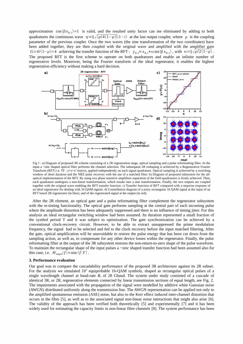
Fig 1 : a) Diagram of proposed 3R scheme consisting of a 2R regeneration stage, optical sampling and a pulse reformatting filter. At theinput a ~sinc shaped optical filter performs the channel selection. The subsequent 2R reshaping is achieved by a Regenerative FourierTransform (RFT) i.e. TF : y=x+π-1sin(πx), applied independently on each signal quadrature. Optical sampling is achieved by a switchingwindow of short duration and the NRZ pulse recovery with the use of a matched filter. b) Diagram of proposed subsystem for the all-optical implementation of the RFT. By using two phase sensitive amplifiers separation of the field quadratures is firstly achieved. Then,each quadrature undergoes a non-linear transformation, which results into a sine transformation. Finally, the two outputs are coupledtogether with the original wave enabling the RFT transfer function. c) Transfer function of RFT compared with a stepwise response ofan ideal regenerator for dealing with 16 QAM signals. d) Constellation diagram of a noisy rectangular 16 QAM signal at the input of anRFT based 2R regenerator (in blue), and of the regenerated signal at the output (in red).
characterized by calculating, through direct error counting, the symbol error rate (SER) at the final receiving end.The calculation was as a function of an effective optical signal-to-noise ratio (OSNR), which has been definedby the ratio of the average signal power at the input of the transmission system to the total optical power of thelinearly added noise along the transmission lines (not including the noise introduced by the regenerators). Thisconvention is equivalent to the OSNR of the corresponding linear system, i.e. at the absence of regenerativeelements and provides a common reference for comparing systems of different regenerative properties.
Initially, we investigated the capability of the proposed 3R scheme in compensating timing jitter effects.These phenomena may arise from the non-linear transformation of the incoming pulses with the reshapingelement of the regenerator. In particular, any amplitude distortion on the edges of the pulse, caused either byASE noise or pattern dependent inter-symbol interference, is translated to timing displacements that mayaccumulate along the 2R cascade and affect the per symbol received energy. In Fig. 3a) we have plotted thereceived eye diagram of the 16-QAM signal after 10 cascaded 2R regenerators, having assumed BW parameterequal to 3 and ignored any ASE noise influence in the transmission system. The presence of strong timing jitterdistortion, originating from a pattern dependent inter-symbol interference, is evident. The use of the proposed 3Rscheme leads to a complete elimination of this effect, even for tighter spectral filtering (i.e. BW=1) appliedbefore each 3R regenerator, see Fig. 3b).
Subsequently, we included the ASE noise effects in the transmission system and investigated the tworegeneration scenarios. Fig. 4a) depicts symbol error rate curves as a function of the total OSNR degradation inthe transmission line. The results have been taken for various numbers of cascaded 3R elements and for the inputpower levels of 0 dBm and 10 dBm. Within each regenerator, we have applied matched filtering to the incomingsignal and considered two different values of the switching window (SW), i.e. 2% and 6% of the symbol period,respectively. With SW=2%, significant performance improvements are obtained for 10 dBm. For the same SWand having 0 dBm launched power no significant regeneration gain was observed. This was because the ASEnoise introduced by the 3R subsystem exceeded the added noise of each interconnection link. Specifically, thisnoise power scales proportionally to the square of the SW parameter and although it can be cut down bywidening the switching window an impact on the efficiency of the timing jitter compensation mechanism shouldbe expected. Here we plotted the results for a SW of 6% and 0 dBm signal power, which reveal performancecomparable to the previous case of 10 dBm and SW 2%. This illustrates the trade-off between noise and jitterand makes SW an important optimization parameter.
In Fig. 4b) we have considered the 2R regeneration system and plotted the SER versus OSNR for differentnumber of non-linear elements in cascade. Contrary to the aforementioned 3R scenario, using a matched filter toselect the signal at the input of each regenerator wouldn't allow the system to cascade. So a broader spectralfiltering had to be applied, i.e. by setting BW=4 in this case. Despite the broader filtering, the influence of thetiming jitter has been detrimental. Comparing to the linear system, we could achieve OSNR performance gain(defined for SER:10-3) if more that four regenerative elements are included in the line. Furthermore, with respectto the 3R scenario the OSNR penalty exceeds 4 dB in the limit of 20 cascaded regenerators.
A more detailed comparison of the 3R and 2R systems is depicted in Fig. 4c), where we have calculated the
Fig 2 The regenerative channel model of this study consisting of a number of 3R or 2R regenerators that are placed equidistantly along thetransmission line. Each 3R regenerator is according to the proposed scheme described in Fig. 1a) and Fig 1b). In the 2R case, the optical gateand the pulse reformatting filter which enable the re-timing functionality have been omitted.
Tx3R/2R Rx3R/2R
k=0 k=R k=R+1
Fig 3 : Eye diagrams after 10 regenerators in cascade for the a) 2R and b) 3R case respectively. No ASE noise effects have been taken intoaccount. For the 2R case the BW parameter has been set to 3, whereas a matched filter (i.e. BW=1) has been considered before each 3Rregenerator. Despite the tighter spectral filtering of the second case no pattern dependent is observed, as it has been fully suppressed by theproposed 3R scheme. The switching window (SW) was 2% of the symbol period.
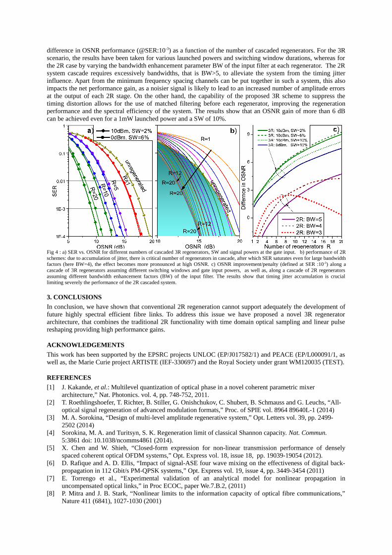
difference in OSNR performance (@SER:10-3) as a function of the number of cascaded regenerators. For the 3Rscenario, the results have been taken for various launched powers and switching window durations, whereas forthe 2R case by varying the bandwidth enhancement parameter BW of the input filter at each regenerator. The 2Rsystem cascade requires excessively bandwidths, that is BW>5, to alleviate the system from the timing jitterinfluence. Apart from the minimum frequency spacing channels can be put together in such a system, this alsoimpacts the net performance gain, as a noisier signal is likely to lead to an increased number of amplitude errorsat the output of each 2R stage. On the other hand, the capability of the proposed 3R scheme to suppress thetiming distortion allows for the use of matched filtering before each regenerator, improving the regenerationperformance and the spectral efficiency of the system. The results show that an OSNR gain of more than 6 dBcan be achieved even for a 1mW launched power and a SW of 10%.
Fig 4 : a) SER vs. OSNR for different numbers of cascaded 3R regenerators, SW and signal powers at the gate input. b) performance of 2Rschemes: due to accumulation of jitter, there is critical number of regenerators in cascade, after which SER saturates even for large bandwidthfactors (here BW=4), the effect becomes more pronounced at high OSNR. c) OSNR improvement/penalty (defined at SER :10-3) along acascade of 3R regenerators assuming different switching windows and gate input powers, as well as, along a cascade of 2R regeneratorsassuming different bandwidth enhancement factors (BW) of the input filter. The results show that timing jitter accumulation is cruciallimiting severely the performance of the 2R cascaded system.
3. CONCLUSIONS
In conclusion, we have shown that conventional 2R regeneration cannot support adequately the development offuture highly spectral efficient fibre links. To address this issue we have proposed a novel 3R regeneratorarchitecture, that combines the traditional 2R functionality with time domain optical sampling and linear pulsereshaping providing high performance gains.
ACKNOWLEDGEMENTS
This work has been supported by the EPSRC projects UNLOC (EP/J017582/1) and PEACE (EP/L000091/1, aswell as, the Marie Curie project ARTISTE (IEF-330697) and the Royal Society under grant WM120035 (TEST).
REFERENCES
[1] J. Kakande, et al.: Multilevel quantization of optical phase in a novel coherent parametric mixer architecture,” Nat. Photonics. vol. 4, pp. 748-752, 2011.
[2] T. Roethlingshoefer, T. Richter, B. Stiller, G. Onishchukov, C. Shubert, B. Schmauss and G. Leuchs, “All-optical signal regeneration of advanced modulation formats,” Proc. of SPIE vol. 8964 89640L-1 (2014)
[3] M. A. Sorokina, “Design of multi-level amplitude regenerative system,” Opt. Letters vol. 39, pp. 2499-2502 (2014)
[4] Sorokina, M. A. and Turitsyn, S. K. Regeneration limit of classical Shannon capacity. Nat. Commun. 5:3861 doi: 10.1038/ncomms4861 (2014).
[5] X. Chen and W. Shieh, “Closed-form expression for non-linear transmission performance of denselyspaced coherent optical OFDM systems,” Opt. Express vol. 18, issue 18, pp. 19039-19054 (2012).
[6] D. Rafique and A. D. Ellis, “Impact of signal-ASE four wave mixing on the effectiveness of digital back-propagation in 112 Gbit/s PM-QPSK systems,” Opt. Express vol. 19, issue 4, pp. 3449-3454 (2011)
[7] E. Torrengo et al., “Experimental validation of an analytical model for nonlinear propagation inuncompensated optical links,” in Proc ECOC, paper We.7.B.2, (2011)
[8] P. Mitra and J. B. Stark, “Nonlinear limits to the information capacity of optical fibre communications,”Nature 411 (6841), 1027-1030 (2001)