Advanced Technology Center 1 HMI HMI - Scherrer Stanford University SDO System Concept Review Lockheed Martin Space Systems Company Advanced Technology Center Solar & Astrophysics Laboratory Palo Alto, CA Stanford University Hansen Experimental Physics Laboratory Stanford, CA Solar Dynamics Observatory System Concept Review Helioseismic and Magnetic Imager Draft Presentation 21 March 2003 Solar Dynamics Observatory
Transcript
Advanced Technology Center
1
HMI
HMI - Scherrer
Stanford University
SDO System Concept Review
Lockheed Martin Space Systems Company
Advanced Technology Center
Solar & Astrophysics Laboratory
Palo Alto, CA
Stanford University
Hansen Experimental Physics Laboratory
Stanford, CA
Solar Dynamics ObservatorySystem Concept Review
Helioseismic and Magnetic ImagerDraft Presentation
21 March 2003
Solar Dynamics Observatory
Advanced Technology Center
2
HMI
HMI - Scherrer
Stanford University
SDO System Concept Review
HMI Science Objectives
B – Solar DynamoC – Global Circulation
H – Far-side Imaging
F – Solar Subsurface Weather
E – Coronal Magnetic Field
I – Magnetic Connectivity
J – Sunspot Dynamics
G – Magnetic Stresses
A – Interior Structure
NOAA 9393
Far-side
D – Irradiance Sources
Advanced Technology Center
3
HMI
HMI - Scherrer
Stanford University
SDO System Concept Review
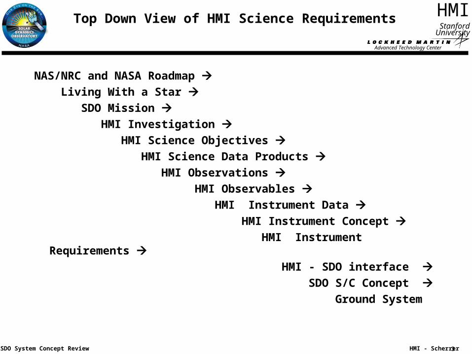
Top Down View of HMI Science Requirements
NAS/NRC and NASA Roadmap Living With a Star SDO Mission HMI Investigation HMI Science Objectives HMI Science Data Products HMI Observations HMI Observables HMI Instrument Data
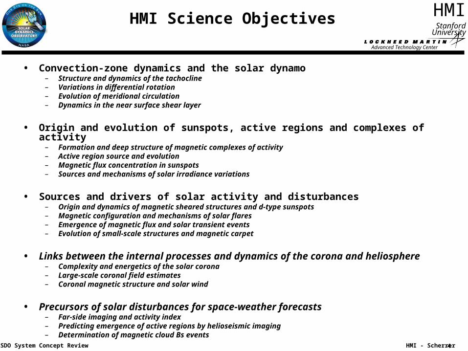
• Convection-zone dynamics and the solar dynamo – Structure and dynamics of the tachocline– Variations in differential rotation– Evolution of meridional circulation– Dynamics in the near surface shear layer
• Origin and evolution of sunspots, active regions and complexes of activity– Formation and deep structure of magnetic complexes of activity– Active region source and evolution– Magnetic flux concentration in sunspots– Sources and mechanisms of solar irradiance variations
• Sources and drivers of solar activity and disturbances – Origin and dynamics of magnetic sheared structures and d-type sunspots– Magnetic configuration and mechanisms of solar flares– Emergence of magnetic flux and solar transient events– Evolution of small-scale structures and magnetic carpet
• Links between the internal processes and dynamics of the corona and heliosphere – Complexity and energetics of the solar corona– Large-scale coronal field estimates– Coronal magnetic structure and solar wind
• Precursors of solar disturbances for space-weather forecasts – Far-side imaging and activity index– Predicting emergence of active regions by helioseismic imaging– Determination of magnetic cloud Bs events
Advanced Technology Center
5
HMI
HMI - Scherrer
Stanford University
SDO System Concept Review
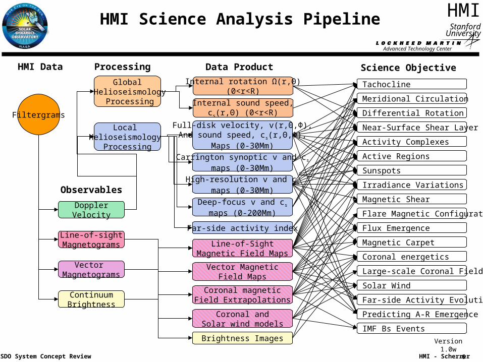
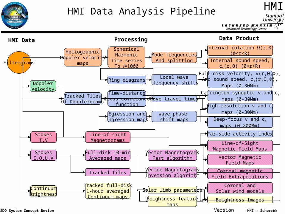
HMI Science Data Products
• HMI Science Data Products
High-level data products which are input to the science analyses. These are time series of maps of physical quantities in and on the Sun.
– Internal rotation Ω(r,Θ) (0<r<R)
– Internal sound speed, cs(r,Θ) (0<r<R)
– Full-disk velocity, v(r,Θ,Φ) and sound speed, cs(r,Θ,Φ) maps (0-30Mm)
– Duration of mission– Completeness of coverage– HMI Science Data Products– Roll accuracy– Time accuracy (months)
• HMI Observations – Duration of sequence– Cadence – Completeness (95% of data sequence)– Noise– Resolution– Time accuracy (days)
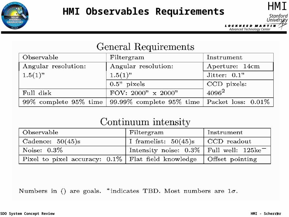
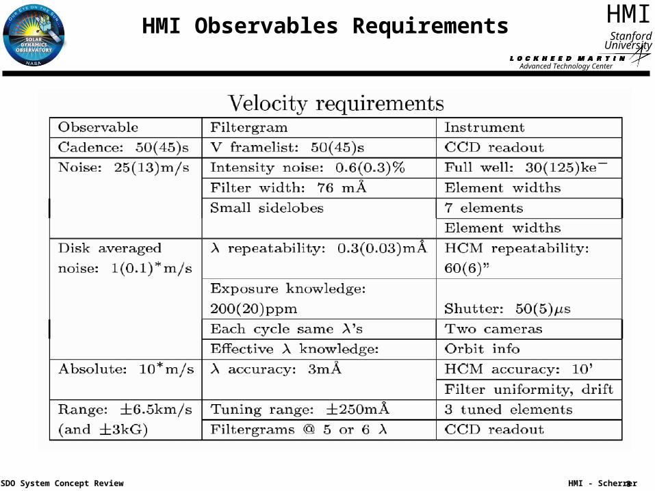
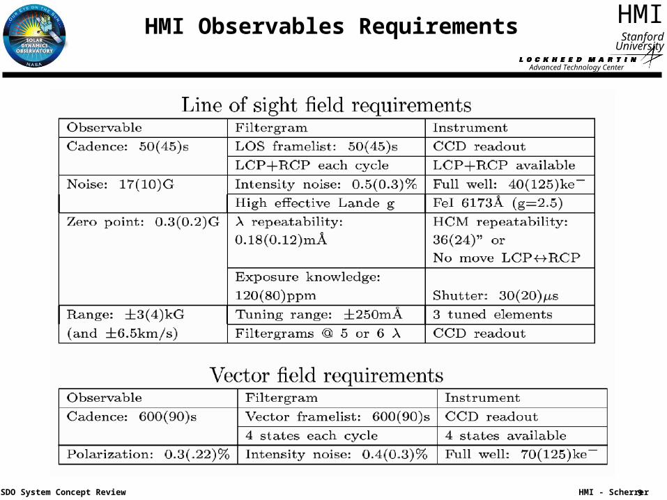
• HMI Observables– Sensitivity– Linearity– Acceptable measurement noise– Image stability– Time rate (minutes) – Completeness (99.9% of observable data in
90s)– Orbit knowledge
• HMI Instrument Data– Accuracy – Noise levels– Completeness (99.99% of data in filtergram) – Tuning & shutter repeatability– Wavelength knowledge– Image registration– Image orientation jitter
• HMI to SDO Interface Requirements• Ground System• Processing System• Data Distribution
Advanced Technology Center
11
HMI
HMI - Scherrer
Stanford University
SDO System Concept Review
Key Requirements
Advanced Technology Center
12
HMI
HMI - Scherrer
Stanford University
SDO System Concept Review
HMI Instrument Concept
• The HMI instrument is an evolution of the successful Michelson Doppler Imager instrument which has been operating on the SOHO spacecraft for over seven years.
• The raw HMI observables are filtergrams of the full solar disk taken with a narrow band (~ 0.1 A bandpass) tunable filter in multiple polarizations.
• The primary science observables are Dopplergrams, line-of-sight magnetograms, vector magnetograms and continuum images computed from a series of filtergrams.
• Some of the key instrument design drivers include maintaining uniform image quality and performance through detailed optical and thermal design and rigorous testing.
• The vector magnetic field measurements are best decoupled from the helioseismology measurements, and a two camera design results to maintain image cadence and separate the two primary data streams.
Advanced Technology Center
13
HMI
HMI - Scherrer
Stanford University
SDO System Concept Review
HMI Optical Layout
Advanced Technology Center
14
HMI
HMI - Scherrer
Stanford University
SDO System Concept Review
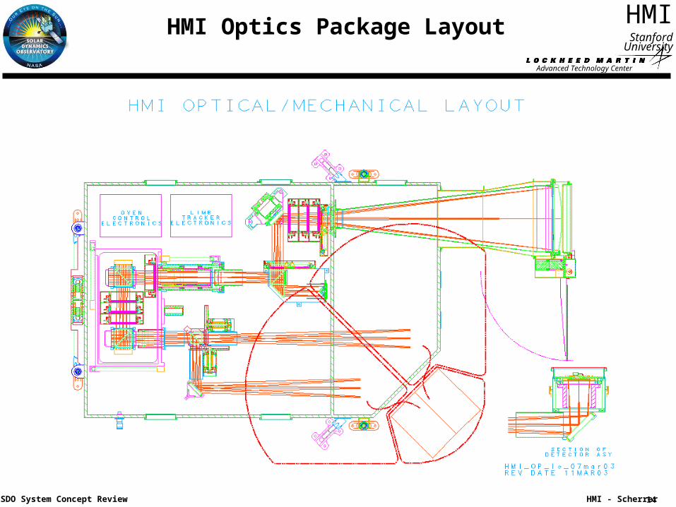
HMI Optics Package Layout
Advanced Technology Center
15
HMI
HMI - Scherrer
Stanford University
SDO System Concept Review
HMI Design Improves on MDI
• The HMI common design features based on MDI:– Front window designed to be the initial filter with widest bandpass.
– Simple two element refracting telescope.
– Image Stabilization System with a solar limb sensor and PZT driven tip-tilt mirror.
– Narrow band tunable filter consisting of a multi-element Lyot filter and two Michelson interferometers.
– Similar hollow core motors, filterwheel mechanisms and shutters.
• The HMI improvements from MDI:– The observing line is the Fe I 617.3 nm absorption line instead of the Ni I 676.8 nm line.
This observing line is used for both Doppler and magnetic measurements.
– Rotating waveplates are used for polarization selection instead of a set of polarizing optics in a filterwheel mechanism.
– An additional tunable filter element is included in order to provide the measurement dynamic range required by the SDO orbit.
– The CCD format will be 4096x4096 pixels instead of 1024x1024 pixels in order to meet the angular resolution requirements.
– Two CCD cameras are used in parallel in order to make both Doppler and vector magnetic field measurements at the required cadence.
– The is no image processor – all observable computation is performed on the ground.
Advanced Technology Center
16
HMI
HMI - Scherrer
Stanford University
SDO System Concept Review
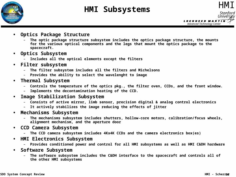
HMI Subsystems
• Optics Package Structure– The optic package structure subsystem includes the optics package structure, the mounts for the
various optical components and the legs that mount the optics package to the spacecraft.
• Optics Subsystem– Includes all the optical elements except the filters
• Filter subsystem– The filter subsystem includes all the filters and Michelsons– Provides the ability to select the wavelenght to image
• Thermal Subsystem– Controls the temperature of the optics pkg., the filter oven, CCDs, and the front window.– Implements the decontamination heating of the CCD.
• Image Stabilization Subsystem– Consists of active mirror, limb sensor, precision digital & analog control electronics– It actively stabilizes the image reducing the effects of jitter
• Mechanisms Subsystem– The mechanisms subsystem includes shutters, hollow-core motors, calibration/focus wheels,
alignment mechanism, and the aperture door
• CCD Camera Subsystem– The CCD camera subsystem includes 4Kx4K CCDs and the camera electronics box(es)
• HMI Electronics Subsystem– Provides conditioned power and control for all HMI subsystems as well as HMI C&DH hardware
• Software Subsystem– The software subsystem includes the C&DH interface to the spacecraft and controls all of the other HMI
subsystems
Advanced Technology Center
17
HMI
HMI - Scherrer
Stanford University
SDO System Concept Review
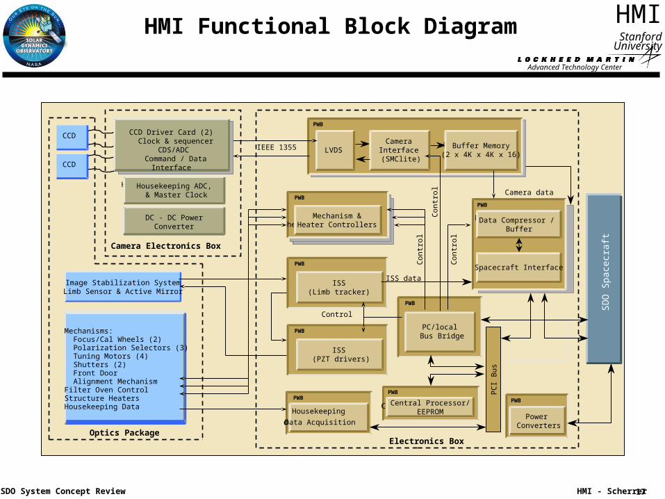
HMI Functional Block Diagram
Buffer memory(2x4Kx4Kx16)
LVDSCamera
interface
(SMClite )
PWB
Mechanism &
heater controllers
PWB
ISS
(Limb tracker)
PWB
PC/local
bus bridge/
EEPROM
PWB
Central processor
PWB
Data compressor
& AEC
PWB
Buffer memory
Housekeeping
data acquisition
PWB
Power
converters
PWB
Camera data
PC
I B
us
ISS
(PZT drivers)
PWB
SD
O S
pace
craf
t
Housekeeping ADC,
& master clockHousekeeping ADC,
& Master Clock
DC -DC power
converter
Camera Electronics Box
IEEE 1355 Buffer memory(2x4Kx4Kx16)Buffer Memory
(2 x 4K x 4K x 16)LVDSLVDS
Camera
interface
(SMClite )
CameraInterface
(SMClite)
PWB
Mechanism &
heater controllersMechanism &
Heater Controllers
PWB
ISS(Limb tracker)
PWB
PC/local
bus bridge/
EEPROM
PWB
PC/local Bus Bridge
PWB
Central processorCentral Processor/EEPROM
PWB
Data compressor
& AECData Compressor /
Buffer
PWB
Buffer memorySpacecraft Interface
Housekeeping
data acquisition
Housekeeping
Data Acquisition
PWB
Power Converters
PWB
Con
trol
Control
ISS data
PC
I B
us
ISS (PZT drivers)
PWB
SD
O S
pace
craf
tS
DO
Spa
cecr
aft
Electronics BoxOptics Package
Image Stabilization SystemLimb Sensor & Active Mirror
CCD
CCD
CCD Driver Card (2) Clock & sequencer
CDS/ADC Command / Data Interface
Mechanisms: Focus/Cal Wheels (2) Polarization Selectors (3) Tuning Motors (4) Shutters (2) Front Door Alignment MechanismFilter Oven ControlStructure HeatersHousekeeping Data
DC - DC Power Converter
Con
trol
Con
trol
Advanced Technology Center
18
HMI
HMI - Scherrer
Stanford University
SDO System Concept Review
Optics Subsystem
• 1 arc-sec diffraction limited image at the sensor– Requires 14 cm aperture
– Requires 4096x4096 pixel sensor
• Solar disk at the sensor 4.9 cm– For sensor with 12 um pixels
• Focus adjustment system with ±3 (TBC) depth of focus range and 16 steps
• Provide calibration mode that images the pupil on the sensor
• Provide beam splitter to divide the telescope beam between the filter oven and the limb tracker
• Provide telecentric beam through the Lyot filter
• Provide beam splitter to feed the output of the filter subsystem to two sensors
• Minimize scattered light on the sensor
Advanced Technology Center
19
HMI
HMI - Scherrer
Stanford University
SDO System Concept Review
Filter subsystem
• Central wavelength 6173Å Fe I line
• Reject 99% of solar heat load from the OP interior
• Total bandwidth 76mÅ FWHM
• Tunable range 500 mÅ
• Very high stability and repeatability required (to be quantified)
• The required bandwidth obtained by cascading filters as follows– Front window 50Å
– Blocker 8Å
– Lyot filter (5 element 1:2:4:8:16) 306 mÅ
– Wide Michelson 172 mÅ
– Narrow Michelson 86 mÅ
• Tuning range requires use of three co-tuned elements– Narrowest Lyot element
– Wide Michelson
– Narrow Michelson
Advanced Technology Center
20
HMI
HMI - Scherrer
Stanford University
SDO System Concept Review
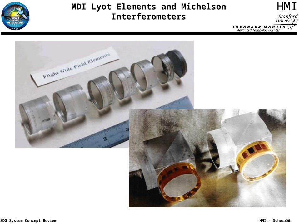
MDI Lyot Elements and Michelson Interferometers
Advanced Technology Center
21
HMI
HMI - Scherrer
Stanford University
SDO System Concept Review
Thermal Subsystem
• Optics package thermal control– Operating temperature range 15 to 25 °C
– Active control to ±0.5 °C
– Control loop in software
• Filter oven– Operating temperature range 35 ± 4 °C
– Temperature accuracy 0.5 °C
– Temperature stability 0.01 °C /hour
– Changes in internal temperature gradients as small as possible
– Dedicated analog control loop in controlled thermal environment
• Sensor (CCD detector) thermal control– Operating –100 °C to –30 °C
– Stability over an orbit xx °C?
– Decontamination mode raise CCD to 20 to 40 °C (may need to be wider because of unregulated power)
• Front window thermal control– Minimize radial gradients
– Return to normal operating temperature within 60 minutes of eclipse exit
Advanced Technology Center
22
HMI
HMI - Scherrer
Stanford University
SDO System Concept Review
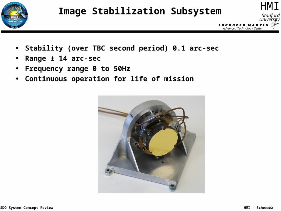
Image Stabilization Subsystem
• Stability (over TBC second period) 0.1 arc-sec
• Range ± 14 arc-sec
• Frequency range 0 to 50Hz
• Continuous operation for life of mission
Advanced Technology Center
23
HMI
HMI - Scherrer
Stanford University
SDO System Concept Review
Mechanisms (1 of 2)
Shutters
• Repeatability 100 us
• Exposure range 50 ms to 90 sec
• Knowledge 30 us
• Life (5 year) 40M exposures
Hollow core motors
• Move time (60 deg) <800 ms
• Repeatability 60 arc-sec
• Accuracy 10 arc-min
• Life (5 year) 80M moves
Advanced Technology Center
24
HMI
HMI - Scherrer
Stanford University
SDO System Concept Review
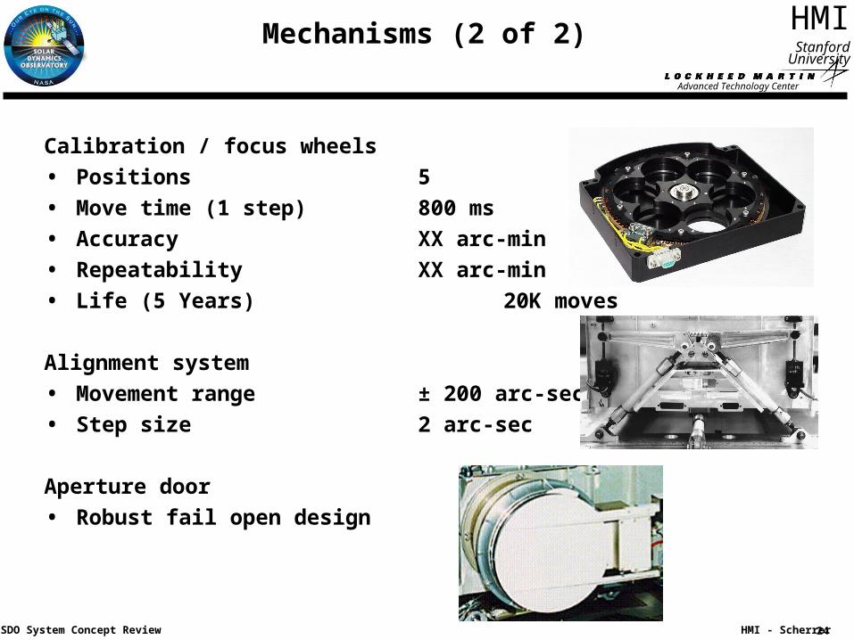
Mechanisms (2 of 2)
Calibration / focus wheels
• Positions 5
• Move time (1 step) 800 ms
• Accuracy XX arc-min
• Repeatability XX arc-min
• Life (5 Years) 20K moves
Alignment system
• Movement range ± 200 arc-sec
• Step size 2 arc-sec
Aperture door
• Robust fail open design
Advanced Technology Center
25
HMI
HMI - Scherrer
Stanford University
SDO System Concept Review
CCD Camera Subsystem
• Format 4096 x 4096 pixels
• Pixel size 12 um
• Full well >125K electrons
• Readout noise 40 electrons
• Readout time <3.4 seconds
• Digitization 12 bits
• Dark current 10 –e/sec/pixel at –60 °C
Advanced Technology Center
26
HMI
HMI - Scherrer
Stanford University
SDO System Concept Review
HMI Electronics Subsystem
• Provide conditioned power and control for all HMI subsystems
• Provide processor for:– Control all of the HMI subsystems
– Decoding and execution of commands
– Acquire and format housekeeping telemetry
– Self-contained operation for extended periods
– Program modifiable on-orbit
• Provide stable jitter free timing reference
• Provide compression and formatting of science data
• Provide interface for 55 Mbps of science date
• Provide spacecraft 1553 interface– Commands 2.5 kbps
– Housekeeping telemetry 2.5 kbps
– Diagnostic telemetry 10 kbps (when requested)
Advanced Technology Center
27
HMI
HMI - Scherrer
Stanford University
SDO System Concept Review
HMI Operations Concept
• The goal of HMI operations is to achieve a uniform high quality data set of solar Dopplergrams and magnetograms.
• A single “Prime Observing Sequence” will run continuously taking interleaved images from both cameras. The intent is to maintain this observing sequence for the entire SDO mission.
• Short calibration sequences are run on a periodic basis (daily or weekly) in order to monitor instrument performance parameters such as focus, filter tuning and polarization .
• Every six months, coordinated spacecraft maneuvers are performed to determine the end-to-end instrument flat-field images and measure solar shape variations.
• HMI commanding requirements will be minimal except to update internal timelines for calibration activities and configuration for eclipses.
• After instrument commissioning, it is anticipated that a single daily command load will be sufficient.
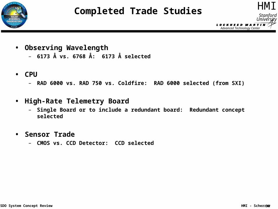
• Observing Wavelength– 6173 Å vs. 6768 Å: 6173 Å selected
• CPU– RAD 6000 vs. RAD 750 vs. Coldfire: RAD 6000 selected (from SXI)
• High-Rate Telemetry Board – Single Board or to include a redundant board: Redundant concept selected
• Sensor Trade– CMOS vs. CCD Detector: CCD selected
Advanced Technology Center
31
HMI
HMI - Scherrer
Stanford University
SDO System Concept Review
Trade Studies In Progress
• Inclusion of redundant mechanisms in HMI Optic Package– Increased reliability vs. Increased cost & mass
– Have allocated volume to not preclude additional mechanisms
• Inclusion of redundant power supply in HMI Electronics Box– Increased reliability versus Increased cost and mass
– Just started this trade
• Camera Subsystem - evaluating two options– Build in-house an evolution of a Solar-B FPP Camera
– Procure from RAL an evolution of a SECCHI Camera
• CCD Configuration– Evaluating operation in front side or back side illuminated mode
Advanced Technology Center
32
HMI
HMI - Scherrer
Stanford University
SDO System Concept Review
HMI CCD and Camera Electronics
• Baseline CCD vendor is E2V– Specification drafted - includes capabilities that allow more optimal camera electronics
design and requires less power– SHARP and HMI to use identical CCDs– E2V to be given a design phase contract ASAP
• Two principal paths for development of camera electronics– Develop cameras in-house => evolution of the Solar-B FPP FG camera– Procure cameras from RAL => evolution of the SECCHI camera
• Key Considerations for decision on approach– Schedule => very critical– Cost => RAL approach less expensive if already doing SHARPP cameras– Performance => both “good enough” but RAL better
• Recommendations if camera electronics are procured from RAL– Baseline same camera for SHARPP and HMI– Have separate RAL subcontracts from LMSAL and NRL– Continue to study FPP-option through Phase A
• Recommendation if camera electronics are developed in house– Do not provide cameras for SHARPP– Keep informed on RAL-for SHARPP camera status and vice versa
Advanced Technology Center
33
HMI
HMI - Scherrer
Stanford University
SDO System Concept Review
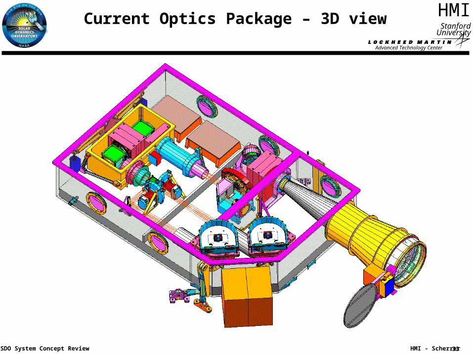
Current Optics Package – 3D view
Advanced Technology Center
34
HMI
HMI - Scherrer
Stanford University
SDO System Concept Review
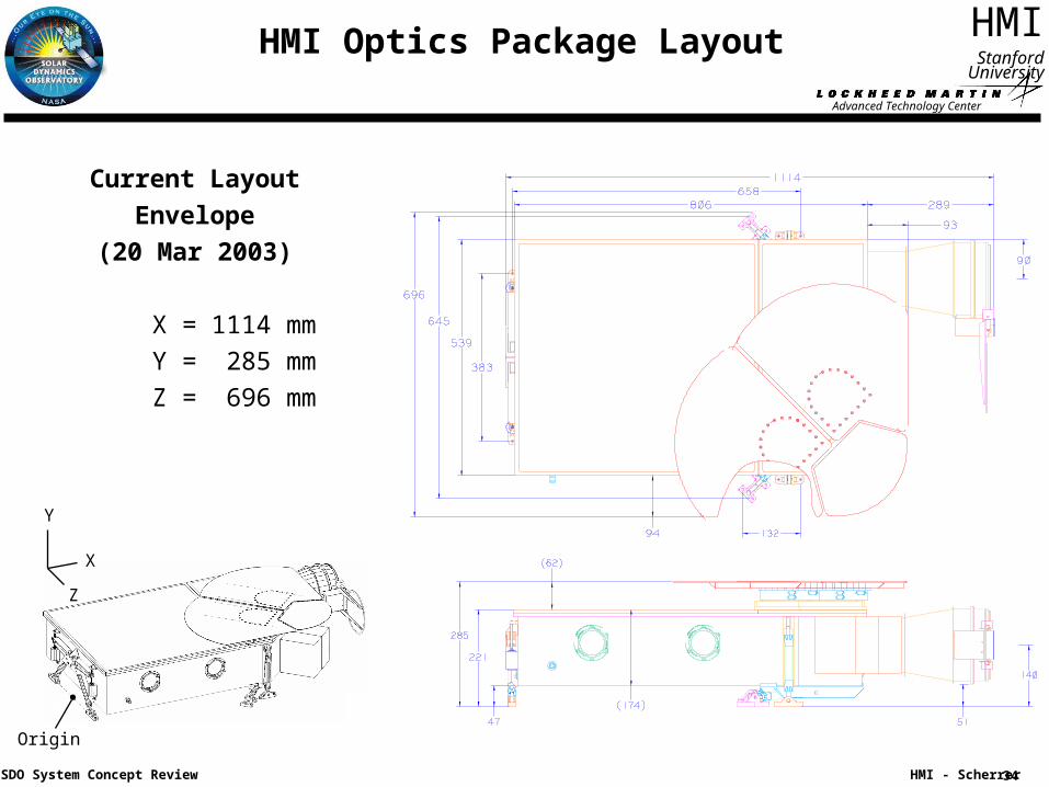
HMI Optics Package Layout
Current Layout
Envelope
(20 Mar 2003)
X = 1114 mm
Y = 285 mm
Z = 696 mm
Y
X
Z
Origin
Advanced Technology Center
35
HMI
HMI - Scherrer
Stanford University
SDO System Concept Review
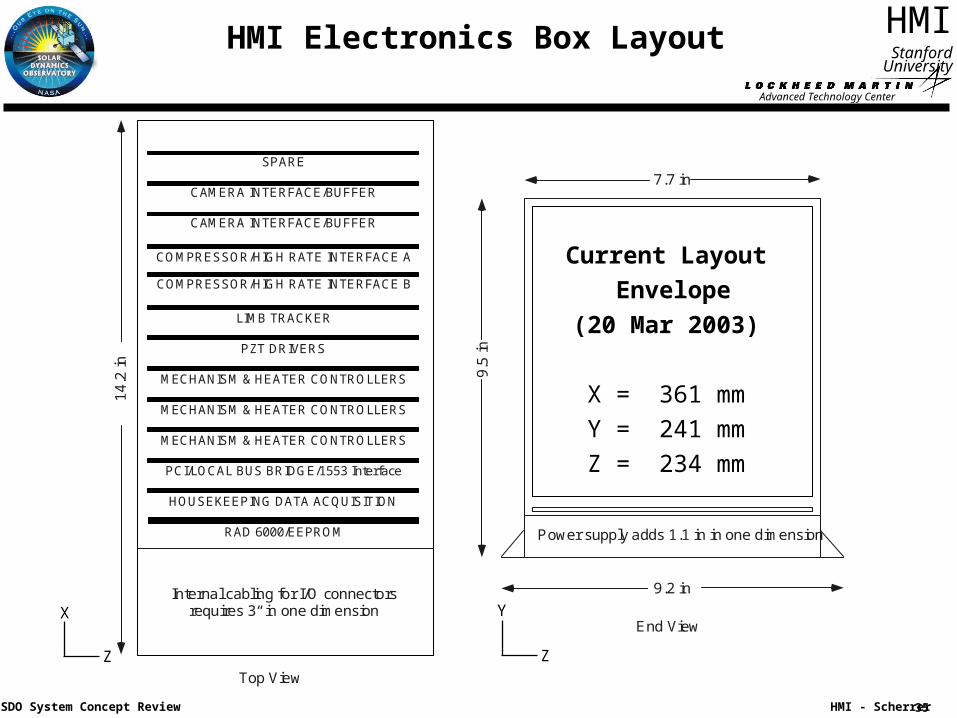
9.2 in
Power supply adds 1.1 in in one dimension
9.5
in
7.7 in
End View
RAD 6000/EEPROM
HOUSEKEEPING DATA ACQUISITION
PCI/LOCAL BUS BRIDGE/1553 Interface
PZT DRIVERS
LIMB TRACKER
CAMERA INTERFACE/BUFFER
CAMERA INTERFACE/BUFFER
MECHANISM & HEATER CONTROLLERS
MECHANISM & HEATER CONTROLLERS
MECHANISM & HEATER CONTROLLERS
SPARE
COMPRESSOR/HIGH RATE INTERFACE A
COMPRESSOR/HIGH RATE INTERFACE B
Internal cabling for I/O connectorsrequires 3“ in one dimension
14.
2in
Top View
HMI Electronics Box Layout
Current Layout
Envelope
(20 Mar 2003)
X = 361 mm
Y = 241 mm
Z = 234 mm
X
Z
Y
Z
Advanced Technology Center
36
HMI
HMI - Scherrer
Stanford University
SDO System Concept Review
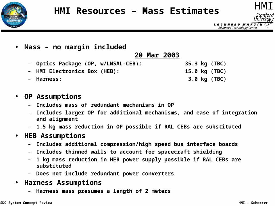
HMI Resources – Mass Estimates
• Mass – no margin included20 Mar 2003
– Optics Package (OP, w/LMSAL-CEB): 35.3 kg (TBC)
– HMI Electronics Box (HEB): 15.0 kg (TBC)
– Harness: 3.0 kg (TBC)
• OP Assumptions– Includes mass of redundant mechanisms in OP
– Includes larger OP for additional mechanisms, and ease of integration and alignment
– 1.5 kg mass reduction in OP possible if RAL CEBs are substituted
• HEB Assumptions– Includes additional compression/high speed bus interface boards
– Includes thinned walls to account for spacecraft shielding
– 1 kg mass reduction in HEB power supply possible if RAL CEBs are substituted
– Does not include redundant power converters
• Harness Assumptions– Harness mass presumes a length of 2 meters
Advanced Technology Center
37
HMI
HMI - Scherrer
Stanford University
SDO System Concept Review
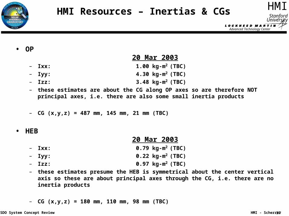
HMI Resources – Inertias & CGs
• OP 20 Mar 2003
– Ixx: 1.00 kg-m2 (TBC)
– Iyy: 4.30 kg-m2 (TBC)
– Izz: 3.48 kg-m2 (TBC)
– these estimates are about the CG along OP axes so are therefore NOT principal axes, i.e. there are also some small inertia products
– CG (x,y,z) = 487 mm, 145 mm, 21 mm (TBC)
• HEB 20 Mar 2003
– Ixx: 0.79 kg-m2 (TBC)
– Iyy: 0.22 kg-m2 (TBC)
– Izz: 0.97 kg-m2 (TBC)
– these estimates presume the HEB is symmetrical about the center vertical axis so these are about principal axes through the CG, i.e. there are no inertia products
– CG (x,y,z) = 180 mm, 110 mm, 98 mm (TBC)
Advanced Technology Center
38
HMI
HMI - Scherrer
Stanford University
SDO System Concept Review
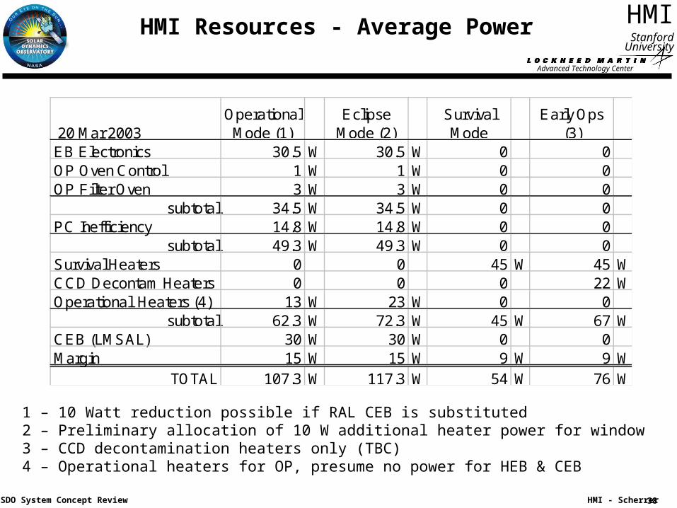
HMI Resources - Average Power
20 Mar 2003Operational
Mode (1)Eclipse
Mode (2)SurvivalMode
Early Ops(3)
EB Electronics 30.5 W 30.5 W 0 0OP Oven Control 1 W 1 W 0 0OP Filter Oven 3 W 3 W 0 0
subtotal 34.5 W 34.5 W 0 0PC Inefficiency 14.8 W 14.8 W 0 0
subtotal 49.3 W 49.3 W 0 0Survival Heaters 0 0 45 W 45 WCCD Decontam Heaters 0 0 0 22 WOperational Heaters (4) 13 W 23 W 0 0
subtotal 62.3 W 72.3 W 45 W 67 WCEB (LMSAL) 30 W 30 W 0 0Margin 15 W 15 W 9 W 9 W
TOTAL 107.3 W 117.3 W 54 W 76 W
1 – 10 Watt reduction possible if RAL CEB is substituted2 – Preliminary allocation of 10 W additional heater power for window3 – CCD decontamination heaters only (TBC)4 – Operational heaters for OP, presume no power for HEB & CEB
Advanced Technology Center
39
HMI
HMI - Scherrer
Stanford University
SDO System Concept Review
HMI Resources – Mass Estimates
• Mass – no margin included20 Mar 2003
– Optics Package (OP, w/LMSAL-CEB): 35.3 kg (TBC)
– HMI Electronics Box (HEB): 15.0 kg (TBC)
– Harness: 3.0 kg (TBC)
• OP Assumptions– Includes mass of redundant mechanisms in OP
– Includes larger OP for additional mechanisms, and ease of integration and alignment
– 1.5 kg mass reduction in OP possible if RAL CEBs are substituted
• HEB Assumptions– Includes additional compression/high speed bus interface boards
– Includes thinned walls to account for spacecraft shielding
– 1 kg mass reduction in HEB power supply possible if RAL CEBs are substituted
– Does not include redundant power converters
• Harness Assumptions– Harness mass presumes a length of 2 meters
Advanced Technology Center
40
HMI
HMI - Scherrer
Stanford University
SDO System Concept Review
HMI Resources - Telemetry
• Telemetry Data Rate– Nominal science data: 55 Mbits/sec (Split between two interfaces)
– Housekeeping data: 2.5 kb/sec
– Diagnostics data: 10 kb/sec
– Command uplink: 2.6 kb/sec (max)
Advanced Technology Center
41
HMI
HMI - Scherrer
Stanford University
SDO System Concept Review
Spacecraft Resource Drivers
• Data Continuity & Completeness– Capture 99.99% of the HMI data (during 90 sec observing periods)
– Capture data 95% of all observing time
• Spacecraft Pointing & Stability– The spacecraft shall maintain the HMI reference boresight to within 200 arcsec of sun
center
– The spacecraft shall maintain the HMI roll reference to within TBD arcsec of solar North
– The spacecraft shall maintain drift of the spacecraft reference boresight relative to the HMI reference boresight to within 14 arcsec in the Y and Z axes over a period not less than one week.
– The spacecraft jitter at the HMI mounting interface to the optical bench shall be less than 5 arcsec (3 sigma) over frequencies of 0.02 Hz to 50 Hz in the X, Y and Z axes.
• Reference Time– Spacecraft on-board time shall be accurate to 100 ms with respect to ground time
(goal of 10 ms)
Advanced Technology Center
42
HMI
HMI - Scherrer
Stanford University
SDO System Concept Review
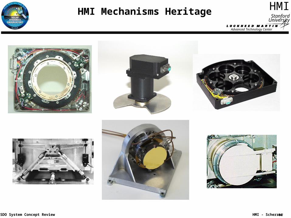
HMI Heritage
• The primary HMI heritage is the Michelson Doppler Imager instrument which has been successfully operating in space for over 7 years. Between launch in December 1995 and March 2003, almost 70 million exposures have been taken by MDI.
• Most of the HMI sub-systems are based on designs developed for MDI and subsequent space instruments developed at LMSAL.
– Lyot filter has heritage from Spacelab-2/SOUP, SOHO/MDI, Solar-B/FPP instruments.
– HMI Michelson interferometers will be very similar to the MDI Michelsons.
– Hollow core motors, filterwheel mechanisms, shutters and their controllers have been used in SOHO/MDI, TRACE, SXI, Epic/Triana, Solar-B/FPP, Solar-B/XRT, Stereo/SECCHI.
– The Image Stabilization System is very similar to the MDI design, and aspects of the ISS have been used in TRACE and Stereo/SECCHI.
– The main control processor planned for HMI is being used on the SXI and Solar-B/FPP instruments.
Advanced Technology Center
43
HMI
HMI - Scherrer
Stanford University
SDO System Concept Review
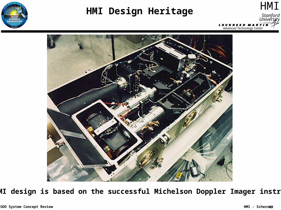
HMI Design Heritage
The HMI design is based on the successful Michelson Doppler Imager instrument.
CCD detector Camera electronics Fabricate ISS Fabricate electronics
Telescope structure
Lyot element fabrication
Optics fabrication
Entrance filter
Michelsonsfabrication
Oven & controller fabrication
Fabricate mechanisms
Fabricate focal plane
Assemble & align on optical bench
Verify optics performance
HMI functional test
HMI environmental test
HMI calibration
Spacecraft I&T
Launch & commissioning
Integrate &align telescope
Test & calibrate ISS
Develop Software
Advanced Technology Center
47
HMI
HMI - Scherrer
Stanford University
SDO System Concept Review
Environmental Test Approach
• In general environmental test will be done at the integrated HMI level to protoflight levels & durations
• The preferred order of testing is:– LFFT
– SPT for Calibration
– SPT for Sunlight Performance
– EMI/EMC
– LFFT
– Sine & Random Vibration
› Electronics & Optics Package separately
› Powered off
– LFFT
– Thermal Vacuum / Thermal Balance
– LFFT
– SPT for Calibration
– SPT for Sunlight Performance in vacuum
– Mass Properties
– Delivery
Advanced Technology Center
48
HMI
HMI - Scherrer
Stanford University
SDO System Concept Review
Instrument Calibration Approach
• Critical subsystems will be calibrated at LMSAL prior to integration these include
– The CCD cameras
– The Michelsons
– The Lyot filter
– Mechanisms
– Other optical elements
• The completed HMI will be calibrated at LMSAL using lasers, the stimulus telescope and the Sun
• The completed HMI will be calibrated at LMSAL in vacuum using both the stimulus telescope and the Sun
Advanced Technology Center
49
HMI
HMI - Scherrer
Stanford University
SDO System Concept Review
Functional Test Approach
• HMI will use a structured test approach so that the test at each point in the program can be appropriate to the need and consistent test results can be obtained
• The tests will be controlled by STOL procedures running in the EGSE and will use released test procedures
• The Aliveness test will run in less than 30 minutes and will do a quick test of the major subsystems
• The Short Form Functional Test (SFFT) will run in a few hours and will test all subsystems but will not test all modes or paths. It will not require the stimulus telescope
• The Long Form Functional Test (LFFT) will run in about 8 hours and will attempt to cover all paths and major modes. The SFFT is a subset of the LFFT. The LFFT will require the use of the stimulus telescope
• Special Performance Tests (SPT) are tests that measure a specific aspect of the HMI performance. These are detailed test that require the stimulus telescope or other special setups. They are used only a few times in the program
Advanced Technology Center
50
HMI
HMI - Scherrer
Stanford University
SDO System Concept Review
HMI Functional Test on Observatory
• SFFT / LFFT / SPT are derived from Instrument level tests
• We assume that GSFC will provide an interface to the HMI EGSE so the same EGSE system can be used to test HMI after integration onto the spacecraft
• We will use the HMI stimulus telescope to verify HMI calibration while HMI is mounted on the spacecraft
• We recommend the inclusion of a spacecraft level jitter compatibility test
Advanced Technology Center
51
HMI
HMI - Scherrer
Stanford University
SDO System Concept Review
Schedule and Critical Path
Advanced Technology Center
52
HMI
HMI - Scherrer
Stanford University
SDO System Concept Review
Risks Assessment – Instrument Development
• Filter performance:– The Lyot filter and Michelson interferometers are the heart of the HMI instrument.
Although we have previously built these filters for the MDI instrument, there are relatively few vendors with the specialized skills necessary for their fabrication. We are working aggressively to develop detailed filter specifications and identify potential vendors.
• Mechanisms longevity :– Although the hollow core motor and shutter planned for HMI have significant flight
heritage, the required number of mechanism moves is of concern. Lifetests of the hollow core motors and shutters are planned to validate their performance for the planned SDO mission duration.
• Thermal performance:– The thermal stability of the HMI instrument is critical to achieving it’s ultimate
performance. Detailed thermal modeling and subsystem thermal testing will be used to optimize the thermal design.
Advanced Technology Center
53
HMI
HMI - Scherrer
Stanford University
SDO System Concept Review
Risks Assessment - Programmatic
• HMI camera electronics has potential schedule/cost impact:– Obtaining SECHHI derived camera electronics from the Rutherford Appleton Laboratory
in the UK is a viable option for HMI, but the development schedule is not know in detail. If this option is chosen, we feel it is best that we obtain the camera electronics directly from RAL.
– A modified Solar-B/FPP camera electronics developed by LMSAL will also meet the HMI requirements. This option has less schedule risk, but costs and camera power and mass are higher than the RAL camera.
• Timely negotiation of HMI Product Assurance Implementation Plan