12/7/2016 1 by Prof. Deepankar Choudhury, PhD Humboldt Fellow, JSPS Fellow, BOYSCAST Fellow, TWAS-VS Fellow Professor, Dept. of Civil Engg., IIT Bombay, Mumbai, India. Also, Adjunct Professor, Academy of CSIR (AcSIR), New Delhi, India. Advances in Design and Practice for Combined Pile-Raft Foundation (CPRF) under Earthquake Conditions Lecture at Conference of IAStructE, New Delhi on 7 th December, 2016 Deepankar Choudhury, IIT Bombay, India * PhD Scholars : Mr. Ashutosh Kumar, Dr. Kaustav Chatterjee, Dr. V. S. Phanikanth, Mr. Milind Patil, Ms. Sujatha Manoj. * Collaborators : Prof. Rolf Katzenbach, TU Darmstadt, Germany; Prof. Harry Poulos, Australia. * Funding Agencies: British Petroleum, UK; Alexander von Humboldt Foundation, Germany; ThyssenKrupp Pvt. Ltd., Germany, NPCIL, India, Chemie-Tech. Pvt. Ltd., India. * Society/Code Committee: ISSMGE TC 212 - Deep Foundations , International Building Code (IBC-1803), USA Acknowledgements 2
Professor, Dept. of Civil Engg., IIT Bombay, Mumbai, India.Also, Adjunct Professor, Academy of CSIR (AcSIR), New Delhi, India.
Advances in Design and Practice for Combined Pile-Raft Foundation (CPRF)
under Earthquake Conditions
Lecture at Conference of IAStructE, New Delhi on 7th December, 2016
Deepankar Choudhury, IIT Bombay, India
* PhD Scholars : Mr. Ashutosh Kumar, Dr. KaustavChatterjee, Dr. V. S. Phanikanth, Mr. Milind Patil, Ms. SujathaManoj.
* Collaborators : Prof. Rolf Katzenbach, TU Darmstadt,Germany; Prof. Harry Poulos, Australia.
* Funding Agencies: British Petroleum, UK; Alexander vonHumboldt Foundation, Germany; ThyssenKrupp Pvt. Ltd.,Germany, NPCIL, India, Chemie-Tech. Pvt. Ltd., India.
* Society/Code Committee: ISSMGE TC 212 - DeepFoundations , International Building Code (IBC-1803), USA
Acknowledgements
2
12/7/2016
2
3
Glory of Deep Foundations
7 December 2016
Burj Khalifa, Dubai
Poulos and Bunce (2008)
Introduction - Super Tall Towers
ongoing construction boom - supertall towers of 200 to 600 m
- 800 to 1000m tall vertical cities
12/7/2016
3
5
Future of Deep Foundations
7 December 2016
Proposed Kingdom Tower, 1001 m, Jeddah
Katzenbach, Choudhury and Chang (2013)
Foundation system of World’s Tallest (1001m) Building at Jeddah
Foundation raft (4.5 m thick)
Piles (45 m long)
Piles (65 m long)
Katzenbach, Choudhury and Chang (2013)
12/7/2016
4
Concept of Combined Pile-Raft Foundation (CPRF)
Skin friction Pile
Foundations
Raft foundation Deep (Pile) foundation Combined Pile-Raft Foundation (CPRF)
Base pressure
INTRODUCTION to CPRF
Piled raft foundation(also called composite foundation)solve:
1. Settlement – through interaction and load sharing.2. Differential settlement – raft provide stiffness
against load.3. Economical - reducing number of piles.
Poulos et al. (2001) has examined a number ofidealized soil profiles, and found that soil profilesconsisting of relatively stiff clays and relativelydense sands may be favourable for piled raftfoundation.
Construction: 1988 - 1990
Foundation: CPRF
Height: 256 m Messeturm tower, Germany
(Katzenbach et al. 2005)8
12/7/2016
5
9
• CPRF (Composite foundation ) – shallow(raft) + Deep(pile) foundation
• Cost optimized solution for the foundations of HIGH RISE BUILDINGS
• Reduces differential settlement (raft provide stiffness against load)
D. Choudhury, IIT Bombay, India
ISSMGE CPRF guideline by TC 212 – Deep Foundation, 2013
INTRODUCTION to CPRF
→ → Combined Pile-Raft Foundation (CPRF) Katzenbach et al. (2009)
Settlements calculated for a shallow foundation:s > 40 cmz = 0 - 20 m → 75 - 80 %
Messeturm · Frankfurt am Main, Germany
Settlements:
Messeturm · Frankfurt am Main, Germany
12/7/2016
6
Accomplished: CPRF of 64 piles (laverage = 30 m)
Costs of pile production: 64 piles of 30 m at 780 US$/m 1.5 Mio. US$
Pile foundation: 316 piles (l = 30 m)
Costs of pile production: 316 piles of 30 m at 780 US$/m 7.4 Mio. US$
Savings in costs of pile production 5.9 Mio. US$
Comparison of costs for the piles
Messeturm · Frankfurt am Main, Germany
Katzenbach and Choudhury (2011)
International Design Guideline for CPRF –by ISSMGE TC 212 – Deep Foundations (2013)
7 December 2016Eds. Katzenbach and Choudhury (2013)
12/7/2016
7
dydxy,x,s)s(R k,raft
m
1jk,raftj,k,pilek,tot sRsRsR
sRsRsR j,k,sj,k,bj,k,pile
Total resistance of the CPRF:
Pile resistance:
Raft resistance:
Bearing concept of a Combined Pile-Raft Foundation (CPRF)
Katzenbach and Choudhury (2013)
Analytical study:
14
Katzenbach et al. (2011) suggested that designing Combined Pile-Raft Foundations (CPRF) requires the qualified understanding of soil-structure interaction.
Rtotal,k = ΣRpile,k, j + RRaft, k
Total resistance of the CPRF:
Pile resistance: sRsRsR jksjkbjkpile ,,,,,,
Raft resistance: dydxyxssR kraft ,,)(,
αCPRF is set between 0.45-0.55
s =
(Katzenbach and Choudhury, 2013).
, ,1
,
( )
( )
m
p i le k jj
C P R Fto t k
R s
R s
CPRF coefficient:
12/7/2016
8
Cost efficiency analysis of CPRF
Pile Foundation CPRF
Approximate weight of 50 storey building over 50m2 area= 25000kN
assume pile axial resistance= 2000kN
No.of piles in pile foundationTotal superstructure load=
axial resistance in single pile
No.of piles in CPRFTotal superstructure load=
axial resistance in single pileCPRF
25000Number of piles= =12.5 132000
0.5 25000Number of piles= =6.25 72000
no. of piles in CPRFCPRF efficiency= no. of piles in pile foundation alone
CPRF CPRF PFCost Cost
Suitable FOS may be adopted in finding the superstructure load and axial resistance of piles
Tall Tower ProjectPreliminary Site Investigation
(e.g. Desktop Study, Geological Model, Risk Assessment, etc.
Moderate Risk
Low Risk
High Risk
Ground Investigation
(disturbed sampling, coring)
General Testing(Sieve Analysis, AtterbergLimits, UCS, Point Loads)
Empirical Correlations
Dominate
Ground Investigation(as for Low Risk + the
followings)
In-situ Testing(e.g. PMT, Packer, FHT)
General Testing
(as for Low Risk)
Site Specific Correlations
Preliminary Ground
Investigation(as for Low Risk)
In-situ Testing
(identify critical zones)
Detailed Ground
InvestigationHigh Quality Undisturbed
Samples
Site Specific Correlations
High Quality Laboratory Testing
(Triaxial)
12/7/2016
9
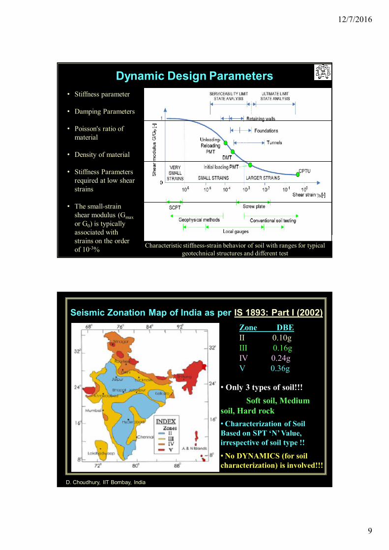
Dynamic Design Parameters
Characteristic stiffness-strain behavior of soil with ranges for typical geotechnical structures and different test
• Stiffness parameter
• Damping Parameters
• Poisson's ratio of material
• Density of material
• Stiffness Parameters required at low shear strains
• The small-strain shear modulus (Gmaxor G0) is typically associated with strains on the order of 10-3%
D. Choudhury, IIT Bombay, India
Seismic Zonation Map of India as per IS 1893: Part I (2002)Zone DBEII 0.10gIII 0.16gIV 0.24gV 0.36g
• Only 3 types of soil!!!Soft soil, Medium
soil, Hard rock• Characterization of Soil Based on SPT ‘N’ Value, irrespective of soil type !!
• No DYNAMICS (for soil characterization) is involved!!!
12/7/2016
10
Soil Classification for Seismic Design in USA (NEHRP)
Choudhury (2010) in Structural Longivity, 3(2), 155-170.
Also getting included in International Building Code (IBC 1803 on Foundations), USA.
Dr. Deepankar Choudhury, IIT Bombay
Soil Classification as per Eurocode 8 (2004)
12/7/2016
11
21Deepankar Choudhury, IIT Bombay
• Base isolation technique adopted(Peak acceleration at 1st and 12thfloor – 0.527m/s2 and 0.619m/s2
respectively whereas PGA was 1.748m/s2
• Very little effect of earthquake of suchlarge magnitude felt on CPRFmagnitude which lead to very minordisturbance in the building
Yamashita et al. (2012) – Field data from Tohuku Earthquake• Reported the performance of CPRF of a twelve
storey building (38.7m high) of Tokyo, Japan foundedon silty sand in Mw=9, 2011 Tohoku earthquake
• Ground improvement technique(deep soil mixing)was adopted to improve the ground and baseisolation was done
Building photo and ground displacement, (Yamashita et al. 2012)
22Deepankar Choudhury, IIT Bombay
Three dimensional view of soil and CPRF model in PLAXIS3D
Response of CPRF under Pseudo-static load
Kumar, A., Choudhury, D. and Katzenbach,R. (2016). In International Jounral ofGeomechanics, ASCE, doi:10.1061/(ASCE)GM.1943-5622.0000637.
Seismically induced load isreplaced with equivalent statichorizontal load, equal to seismiccoefficient times the vertical load.
Seismically induced loads areapplied at the level of raft and isnamed as pseudo-statichorizontal load in the presentstudy.
12/7/2016
12
23D. Choudhury, IIT Bombay, India
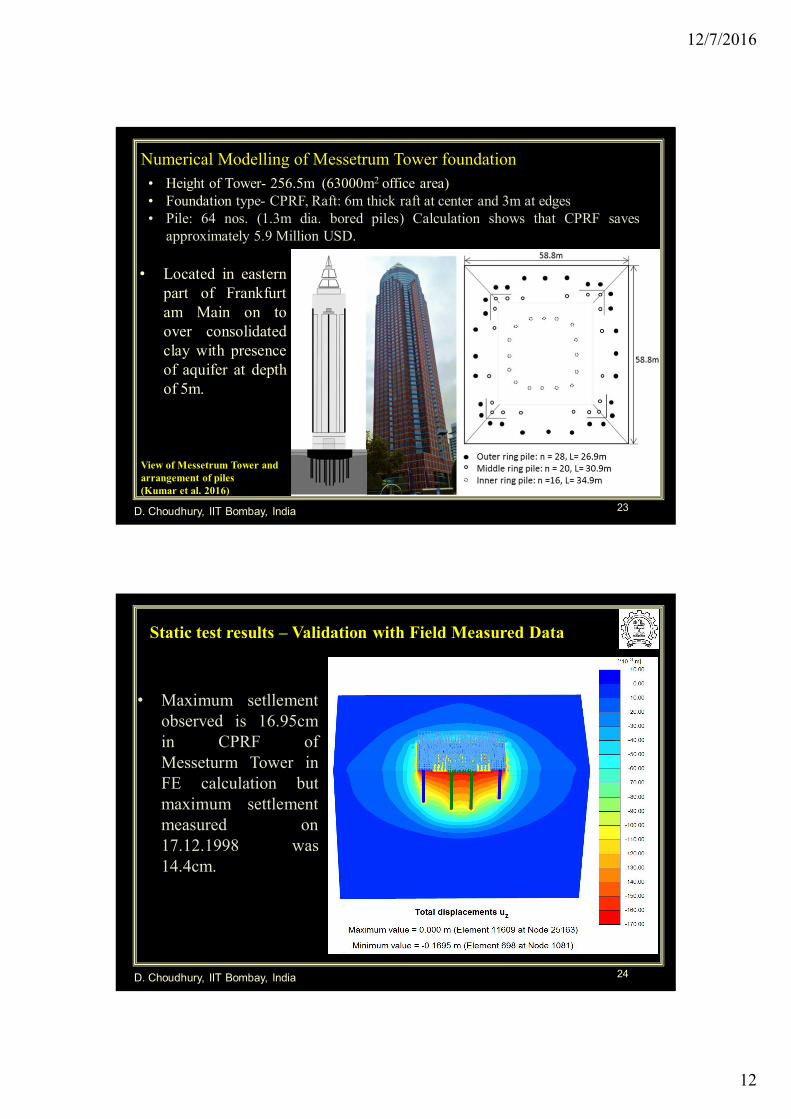
Numerical Modelling of Messetrum Tower foundation • Height of Tower- 256.5m (63000m2 office area)• Foundation type- CPRF, Raft: 6m thick raft at center and 3m at edges• Pile: 64 nos. (1.3m dia. bored piles) Calculation shows that CPRF saves
approximately 5.9 Million USD.
View of Messetrum Tower and arrangement of piles (Kumar et al. 2016)
• Located in easternpart of Frankfurtam Main on toover consolidatedclay with presenceof aquifer at depthof 5m.
24
Static test results – Validation with Field Measured Data
D. Choudhury, IIT Bombay, India
• Maximum setllementobserved is 16.95cmin CPRF ofMesseturm Tower inFE calculation butmaximum settlementmeasured on17.12.1998 was14.4cm.
12/7/2016
13
25
Recent Major Projectson
Design of CPRF1. Oil Tank Foundations in Iraq – for BP, UK.
2. Heavy material Storage Unit Foundation in
Vietnam – for ThyssenKrupp, Germany.
3. NB Foundation in India – for NPCIL, India.
D. Choudhury, IIT Bombay, India
26
Project completedon
“Seismic Design of Foundation System for
Oil Tanks at SKA terminal, Iraq”
Owner: British Petroleum, UK.Involved Geotechnical Agencies & Experts:
• The site is located approximately 40 km south of Basrah in the Free Trade
zone at KAFZA in Iraq (Latitude 47.9294οN and Longitude 30.0342οE)
• It is Iraq’s third largest port in scale of size and for goods shipped to the
port of Basrah
Seismic Design of CPRF and DSSI analysis
Kumar, A. and Choudhury, D.(2016). in Proc. of the ICE – Geo.Eng.169,(2), 129–138.
28D. Choudhury, IIT Bombay, India
Typical Soil property of the site (Ref: Fugro, Dubai)• Fine to medium silica sand as fill material at
top• Below it, very soft to soft clay underlain by
stiff clay encountered• Dense sand extends to greater depth at bottom
12/7/2016
15
29D. Choudhury, IIT Bombay, India
Description Load Unit
Total Empty Weight 1400 kN
Operating Weight 51000 kN
Hydrotest Weight 62000 kN
Shear Wind 160 kN
Moment Wind 1200 kN.m
'(( tan ) ) ( ) -u i i i Di s c D q p p pQ c K P A cN P N A A L Vertical compression and lateral loading tests are carried out on test pile of
diameter 800 mm and length 26 m Characteristic strength of concrete is 35 N/mm2
Safe vertical capacity is 2052kN The group interaction factor is chosen as 0.65 on the basis of soil
homogeneity, slenderness ratio and pile spacing as per Randolph andWorth (1979)
Loading details and static design of pile
30D. Choudhury, IIT Bombay, India
Seismic Hazard Distribution Map of Iraq (Ref: ARUP)
12/7/2016
16
D. Choudhury, IIT Bombay, India31
Field Pile load test (Ref: Chemie Tech.)
Pile load test result Lateral load test result
• Vertical compression and lateral loadings test are carried out ontest pile of diameter 800 mm and length 26 m
• Characteristics strength of concrete is 35 N/mm2
32
Design Model Layout
View of different layers of soil model and pile arrangement
(89 nos. 800mm dia pile group)D. Choudhury, IIT Bombay, India
12/7/2016
17
D. Choudhury, IIT Bombay, India33
Input acceleration time history used in FLAC3D based on the PSHA report and RSP Match computer programme
Input acceleration time history• The Uniform Hazard Response Spectra (UHRS) is selected from the provided
Probabilistic Seismic Hazard Analysis (PSHA)
• Synthetic earthquake time-history for MCE is generated using RSP Match software
• Target response spectra at the bedrock level and Seed accelerogram are then used to
develop input motion using RSP Match that
is further used as an input in FLAC3D
UHRS for SKA site developed by Mott Macdonald
Dynamic analysis of foundation system
D. Choudhury, IIT Bombay, India34
Modulus reduction curve chosen for different layers of soil
Numerical Fits chosen for soil model as input in FLAC3D to input Hysteresis damping
12/7/2016
18
35D. Choudhury, IIT Bombay, India
Numerical Modelling of soil-pile-raft• Lateral dimension of soil model kept
as four times raft radius to avoidboundary effect
• Grid size near foundationfootprint=0.5m
• Pile as Structural element and raft asshell element
• 89 piles of 800mm diameter and 26mlength and raft thickness- 1.5m ofdiameter 24.1m
36D. Choudhury, IIT Bombay, India
Layer No. Depth (m) Soil typeSoil density
(kg/m3)
Cohesion
(kPa)
Friction
angle
φ (deg)
Modulus of
elasticity (E, kPa)
Poisson’s
ratio
(µ)
1 0 - 2Dense
Sand1800 0 30 50000 0.30
2 2 - 20 Soft Clay 1700 10 0 10000 0.49
3 20-24 Stiff Clay 1700 250 0 70000 0.35
4 24-60
Very
Dense
sand
1900 0 35 60000 0.30
Input Soil and pile parameters in FLAC3D chosen fromexperimental results
MaterialGrade of
concrete
Young’s
Modulus (kPa),
(= 5000(fck)1/2)
(as per IS:456)
Poisson’s ratio
(µ)
Diameter
(m)
Length/thickness
(m)
Pile 35 29500000 0.15 0.8 26
Raft 35 29500000 0.15 24.1 1.5
12/7/2016
19
37D. Choudhury, IIT Bombay, India
Maximum settlement= 23.3mm, Rotation= 5.81x 10⁻⁴, Permissible limit= 1/300 for liquid
storage tank
Vertical settlement contour
38
Axial load contour in pile group in static case
Max. axial force=
697kN
Min. axial force=
478kN
Axial load varying from maximum to minimum magnitude from periphery towards center due to soil-pile-raft interaction
D. Choudhury, IIT Bombay, India
12/7/2016
20
39D. Choudhury, IIT Bombay, India
0
0.1
0.2
0.3
0.4
0.5
0.6
0.7
0.8
0.9
1
1.1
0.0001 0.001 0.01 0.1 1
G/G
max
Cyclic Strain (%)
FLAC3D Input (Depth-(0-2m))
Seed and Idriss, (1970) (Depth-(0-2m))
FLAC3D Input (Depth-(2-24m))
Sun et al. (1988) (PI=20-40%) (Depth-(2-24m))
FLAC3D Input (Depth-(24-60m))
EPRI, (1993) (Depth-(24-60m))
Dynamic soil properties
2 (3 2 ), 0 S 1sM S S
2
2 1
S= L LL L
• Hysteresis damping is taken for soil model that incorporates strain dependentdamping ratio, shear modulus and plasticity based numerical fits.
• To avoid numerical distortion of propagating wave in the dynamic analysisspatial element size must be smaller than approximately one tenth to oneeighth of wave length associated with the highest frequency component ofInput wave
10
L
cf
L
40D. Choudhury, IIT Bombay, India
Construction in progress
12/7/2016
21
41D. Choudhury, IIT Bombay, India
Completed stage
42D. Choudhury, IIT Bombay, India
Summary of CPRF Design Recommendations:Summary of CPRF Design Recommendations:
• The evaluation of displacements and stress resultants are highly importantfactors which govern the response of foundation components
• The factor of safety, defined as ratio of ultimate bearing capacity of CPRF to verticalload together with lateral load should be more than 1.5 (Yamashita et al. 2011)
• The factor of safety, expressed as ratio of ultimate bearing capacity of piles tomaximum axial load obtained in load sharing should be more than 1.5 (Yamashita etal. 2011)
• The connection rigidity between raft and piles should be chosen based onallowable rotation in raft. The permissible angular rotation under static load is1/1000 to 1/500 (AIJ, 2001)
• Soil-raft interaction dominates the design at initial stage of loading but at laterstage pile-soil interaction plays an important role. This peculiar behaviour ofCPRF can be utilized in the actual design depending on the tolerable lateraldisplacement.
• For seismic design of CPRF, the condition of resonance must be checked for thesoil media and the foundation itself
12/7/2016
22
•• Piles have to be set directly under the load of the superstructure. The center of the pile group should be under the center of the loads.
• Few long piles are better than many short piles.
• The length of the piles has to be adapted to the loads. At the edge and the corners of the raft shorter piles and in the inner part of the raft longer piles are recommended.
• Optimum of the CPRF-coefficient: αCPRF = 0.5 … 0.7
Recommendations for the design of CPRF
, ,1
,
( )
( )
m
pile k jj
CPRFtot k
R s
R s
CPRF coefficient:
Dr. Deepankar Choudhury, IIT Bombay, India
For More Details,
(1) Book
(2) Online NPTEL Video Course:
“Soil Dynamics” and“Geotechnical EarthquakeEngineering” – free in YouTube