NEHRP Seismic Design Technical Brief No. 2 Seismic Design of Steel Special Moment Frames A Guide for Practicing Engineers NIST GCR 16-917-41 Ronald O. Hamburger James O. Malley SECOND EDITION This publication is available free of charge from: http://dx.doi.org/10.6028/NIST.GCR.16-917-41
Transcript
NEHRP Seismic Design Technical Brief No. 2
Seismic Design of Steel Special Moment FramesA Guide for Practicing Engineers
NIST GCR 16-917-41
Ronald O. Hamburger James O. Malley
SECOND EDITION
This publication is available free of charge from: http://dx.doi.org/10.6028/NIST.GCR.16-917-41
About the AuthorsRonald O. Hamburger, P.E., S.E., (First and Second Edition),is Head of Structural Engineering, Western Region, for Simpson, Gumpertz, & Heger, Inc. in San Francisco, California. He chaired the American Institute of Steel Construction (AISC) Connection Prequalification Review Panel from 2002-2015, is a member of the AISC Committee on Specifications, and received the Institute’s Higgins award in 2006. He has chaired the ASCE 7 committee, the joint USGS-Building Seismic Safety Council (BSSC) Project 17 and the BSSC’s Provisions Update Committee. Following the 1994 Northridge earthquake, he served as Product Director for Product Development of the SAC Joint Venture.
James O. Malley, P.E., S.E., (First and Second Edition), is Senior Principal with Degenkolb Engineers in San Francisco, California. He chaired the American Institute of Steel Construction (AISC) Task Committee on Seismic Design from 1995-2015. Since 2000 he has served on the AISC’s Committee on Specifications, becoming its chair
About the ReviewersThe contributions of the review panelists for this publication are gratefully acknowledged.
John D. Hooper, P.E., S.E., (Second Edition) is a Senior Principal and Director of Earthquake Engineering at Magnusson Klemencic Associates, a structural and civil engineering firm headquartered in Seattle, Washington. He is a member of the BSSC’s 2015 Provisions Update Committee and chair of the American Society of Civil Engineers Seismic Subcommittee for ASCE 7-16.
Thomas A. Sabol, Ph.D., S.E., A.I.A, (First and Second Edition), is Principal with Englekirk in Los Angeles, California and Adjunct Professor of Civil and Environmental Engineering at the University of California in Los Angeles. He is both a registered structural engineer and architect. He has served as chair of the seismic systems technical committee of the AISC.
C. Mark Saunders, P.E., S.E., (First and Second Edition), is retiredfrom Rutherford+Chekene Consulting Engineers where he was formerlyPresident and Chairman. He has been a member of the AISC TaskCommittee 9 – Seismic Provisions for more than 20 years, most recently asVice Chairman, and as Chairman of Subcommittee 4 on Moment Frames.He is a past president of both the Structural Engineers Association ofNorthern California and ATC.
Andrew W. Taylor, Ph.D., P.E., S.E., FACI, (Second Edition) is an Associate with KPFF Consulting Engineers in Seattle. He is the chair of the American Concrete Institute (ACI) 318 Building Code sub-committee H on Seismic Provisions, a member of the ACI Technical Activities Committee, and chair of the Earthquake Engineering Committee of the Structural Engineers Association of Washington. He is also a member of the ASCE 41 seismic rehabilitation standard committee, and a member of subcommittees of the ASCE 7 seismic design standard.
AcknowledgmentsThis Second Edition supersedes the original edition of NIST GCR 09-917-3, published in June 2009. It is based on information in the originalpublication and includes updated references to codes and standards,updated guidance, and current best practices. ATC, CUREE, and NISTwould like to acknowledge the following additional authors and reviewerswho contributed to developing the original publication, which served asthe basis of this Second Edition:
Helmut Krawinkler, formerly with Stanford University, Stanford, CAScott M. Adan, formerly with Simpson, Gumpertz, & Heger, San Francisco, CADouglas Foutch, University of Illinois at Urbana-Champaign, Urbana, ILRoberto Leon, Virginia Tech, Blacksburg, VA
National Institute of Standards and Technology
NIST is a federal technology agency within the U.S. Department of Commerce that promotes U.S. innovation and industrial competitiveness by advancing measurement science, standards, and technology in ways that enhance economic security and improve our quality of life. NIST is the lead NEHRP agency. Dr. Steven L. McCabe is the Earthquake Engineering Group (EEG) Leader within the Materials and Structural Systems Division of the Engineering Laboratory at NIST. The EEG supports the work of the NEHRP program at NIST.
Applied Technology CouncilThe Applied Technology Council (ATC) is a nonprofit corporation advancing engineering applications for hazard mitigation. This publication is a product of Task Order 15-264 under Contract SB1341-13-CQ-0009 between ATC and NIST. Jon A. Heintz served as theProgram Manager for work conducted under this contract, and ScottSchiff serves as ATC Associate Program Manager on this Task Order.
Consortium of Universities for Research in Earthquake EngineeringThe Consor tium of Universities for Research in Ear thquake Engineering (CUREE) is a nonprofit organization advancing earthquake engineering research, education, and implementation. This publication was produced under a cooperative agreement between ATC and CUREE. Robert Reitherman served as Associate Program Manager overseeing production. Reed Helgens and Darryl Wong served as report production and report preparation consultants for this work.
National Earthquake Hazards Reduction Program (NEHRP) Technical Briefs are published by the National Institute of Standards and Technology (NIST) as aids to the efficient transfer of NEHRP and other research into practice, thereby helping to reduce the nation’s losses resulting from earthquakes.
in 2016. He received the Institute’s T. R. Higgins award in 2010 and a Lifetime Achievement award in 2012. He also serves as a member of the BSSC’s Provision’s Update Committee. Following the 1994 Northridge earthquake, he served as Product Director for Topical Investigations of the SAC Joint Venture.
Consortium of Universities for Research in Earthquake Engineering (CUREE)1301 South 46th Street, Building 420Richmond, CA 94804(510) 665-3529 | [email protected]
Applied Technology Council (ATC)201 Redwood Shores Parkway, Suite 240Redwood City, CA 94065(650) 595-1542 | email: [email protected]
CUREE
NEHRP Seismic Design Technical Briefs
ByApplied Technology Council
In association with the Consortium of Universities for Research in Earthquake Engineering
andRonald O. Hamburger
James O. Malley
June 2016
Prepared forU.S. Department of Commerce
National Institute of Standards and TechnologyEngineering Laboratory
Gaithersburg, MD 20899-8600
Seismic Design of Steel Special Moment Frames
A Guide for Practicing Engineers
NIST GCR 16-917-41
U.S. Department of CommercePenny Pritzker, Secretary
National Institute of Standards and TechnologyWillie E. May, Under Secretary of Commerce for
Standards and Technology and Director
SECOND EDITION
With references to ASCE 7-16, AISC 341-16, and AISC 358-16
This publication is available free of charge from:
http://dx.doi.org/10.6028/NIST.GCR.16-917-41
Disclaimers
This Technical Brief was prepared for the Engineering Laboratory of the National Institute of Standards and Technology (NIST) under the National Earthquake Hazards Reduction Program (NEHRP) Earthquake Structural and Engineering Research Contract SB1341-13-CQ-0009, Task Order 15-264. The contents of this publication do not necessarily reflect the views and policies of NIST or the U.S. Government.
This report was produced by the Applied Technology Council (ATC) in association with the Consortium of Universities for Research in Earthquake Engineering (CUREE). While endeavoring to provide practical and accurate information, ATC, CUREE, the authors, and the reviewers assume no liability for, nor express or imply any warranty with regard to, the information contained herein. Users of information in this report assume all liability arising from such use.
Unless otherwise noted, photos, figures, and data presented in this report have been developed or provided by ATC staff, CUREE staff, or consultants engaged under contract to provide information as works for hire. Any similarity with other published information is coincidental. Photos and figures cited from outside sources have been reproduced in this report with permission. Any other use requires additional permission from the copyright owners.
Certain commercial software, equipment, instruments, or materials may have been used in preparing information contributing to this report. Identification in this report is not intended to imply recommendation or endorsement by NIST, nor is it intended to imply that such software, equipment, instruments, or materials are necessarily the best available for the purpose.
Cover photo—Steel special moment frame under construction.
NIST (2016). Seismic design of steel special moment frames: A guide for practicing engineers, Second Edition, GCR 16-917-41, NEHRP Seismic Design Technical Brief No. 2, produced by the Applied Technology Council and the Consortium of Universities for Research in Earthquake Engineering for the National Institute of Standards and Technology, Gaithersburg, MD.
Introduction ..............................................................................................1The Use of Special Moment Frames................................................................3Principles for Steel Special Moment Frame Design.........................................10Analysis Guidance...................................................................................19Design Guidance.....................................................................................21Additional Requirements...........................................................................26Detailing and Constructability Issues...........................................................29References.............................................................................................33Notations and Abbreviations......................................................................34Credits....................................................................................................36
1. 2.3. 4. 5. 6. 7. 8.9.
10.
Contents
How to Cite This Publication
1Seismic Design of Steel Special Moment Frames: A Guide for Practicing Engineers, Second Edition
Structural steel special moment frames are commonly used as part of the seismic force-resisting systems in buildings designed to resist severe ground shaking and are permitted by ASCE/SEI 7-16, Minimum Design Loads and Associated Criteria for Buildings and Other Structures (ASCE 2016), referred to hereafter as ASCE 7, for any Seismic Design Category without limitation as to height. Beams, columns, and beam-column connections in Steel Special Moment Frames are proportioned and detailed to resist flexural, axial, and shearing actions that result as the building sways through multiple inelastic displacement cycles during strong earthquake ground shaking. Special proportioning and detailing requirements enable these structures to safely resist strong earthquake shaking while experiencing substantial inelastic behavior. These moment frames are called special moment frames by ASCE 7 because of these additional requirements, which improve the inelastic response characteristics of these frames in comparison with less stringently detailed intermediate and ordinary moment frames.
Design requirements for steel special moment frames are contained in a series of standards. ASCE 7, sets the basic loading criteria for steel special moment frames together with associated lateral drift limits. ANSI/AISC 341-16, Seismic Provisions for Structural Steel Buildings (AISC 2016a), referred to hereafter as AISC 341, provides detailed design requirements relating to materials, framing members (beams, columns, and beam-column joints), connections, and construction quality assurance and quality control. In addition, AISC 341 presents requirements for columns that are not designated as part of the seismic force-resisting system. The numerous interrelated requirements for steel special moment frames are covered in several sections of AISC 341, with the primary requirements covered in Section E3. Section E3.6c of AISC 341 references ANSI/AISC 358-16 Prequalified Connections for Special and Intermediate Steel Moment Frames for Seismic Applications (AISC 2016b), referred to hereafter as AISC 358, which facilitates and standardizes the selection and design of steel special moment frame connections to allow their use without the need for project-specific testing. A series of different moment connection details are presented in AISC 358, and additional connections are anticipated to be added in future editions.
1. IntroductionBoth AISC 341 and AISC 358 are applied in conjunction with the ANSI/AISC 360-16, Specification for Structural Steel Buildings (AISC 2016c), referred to hereafter as AISC 360, and AISC 303, Code of Standard Practice for Steel Buildings and Bridges (AISC 2016d), referred to hereafter as AISC 303. AISC 360 is the main AISC specification that provides the design and detailing requirements for all steel buildings. In addition to these standards, American Welding Society (AWS) standards AWS D1.1 Structural Welding Code Steel (AWS 2015) and (AWS) Standard D1.8/D1.8M: 2009, Structural Welding Code—Seismic Supplement (AWS 2009) presents requirements for welding and fabrication that pertain to steel special moment frames.
This Guide is intended for use by practicing structural engineers to assist in their understanding and application of the ASCE 7, AISC 341, AISC 358, and AWS D1.8 standards to steel special moment frame design. The material is presented in a sequence that practicing engineers have found useful, with historic and general principles for seismic design discussed first, followed by system-specific analysis and design requirements. This Guide is also intended to be of value to building officials, educators, and students.
This Guide follows the requirements of the 2016 editions of AISC 341 and AISC 358, along with the pertinent design load requirements specified in ASCE 7. AISC 341 primarily addresses the seismic design of systems in Seismic Design Categories D, E, and F, as defined in ASCE 7. The International Building Code, or IBC, (ICC 2015), which is the code generally adopted throughout the United States, references ASCE 7 for the determination of seismic loads. AISC 341 was developed in parallel with ASCE 7, so the documents are well coordinated regarding terminology, system definition, application limitations, and other issues.
Seismic Design of Steel Special Moment Frames: A Guide for Practicing Engineers, Second Edition
2
Code Requirements versus Guide Recommendations
Building codes present minimum requirements for design and construction of buildings and are legal requirements where adopted by the authority having jurisdiction. Thus, where adopted, AISC 341, AISC 358 and AISC 360, with ASCE 7, must as a minimum be followed. This Guide is written mainly to clarify requirements of the building code and these referenced standards, and it presents other recommendations for good analysis, design, and construction practices that may not be specifically required by the codes or standards. The Guide clearly differentiates between building code requirements and other recommendations.
The main body of text in this Guide emphasizes code requirements and accepted approaches to their implementation. It includes background information and figures to illustrate the requirements. Sections 3 through 6 present analysis, behavior, proportioning, and detailing requirements for steel special moment frames and other portions of the building that interact with these frames. Section 7 presents a discussion of detailing and constructability issues to highlight unique features of steel special moment frame construction. Cited references, notations and abbreviations, and credits are in Sections 8, 9, and 10.
Edition of Codes and Standards
At the time of this publication the International Building Code (ICC 2015) adopts ASCE 7-10, AISC 360-10, and AISC 341-10, which reference AISC 358-10. However, the 2016 editions of these standards have been completed, are anticipated to be adopted by the 2018 International Building Code, and will be available for use in design projects in the near term.
To enable long-term relevance, this publication references the 2016 editions of these standards and the 2018 International Building Code. Substantial changes in these documents from earlier editions affecting the design of steel special moment frames are noted in sidebars. Design engineers are responsible for verifying the currently applicable building code provisions adopted by the authority having jurisdiction over their project. Discussion with and approval by the building official should occur to verify that a later version of a code or standard not yet adopted locally may be used.
The First Edition of this document (NIST CGR 09-917-3) was published in June 2009. The codes and standards referenced in that edition were current as of then but have been updated by the documents referenced in this Second Edition. The First Edition, which may still be relevant in some engineering applications with regards to buildings constructed under the earlier editions of the codes and standards, referenced the 2006 edition of the International Building Code, ASCE 7-05, ANSI/AISC 341-05, ANSI/AISC 358-05, ANSI/AISC 360-05, AISC 303-05, AWS D1.1-2004, and AWS D1.8-2005.
3Seismic Design of Steel Special Moment Frames: A Guide for Practicing Engineers, Second Edition
2.1 Historic Development
Although the concept of a steel special moment frame is a relatively recent development in the building codes, steel moment frames have been in use for more than one hundred years, dating to the earliest use of structural steel in building construction. A notable example of steel building construction in the United States with the frame carrying the vertical loads is the Home Insurance Building in Chicago, a 10-story structure constructed in 1884 with a height of 138 feet (42 m), carrying its gravity loads with a framework of iron and steel members, it is often credited with being the first skyscraper (Figure 2-1). This and other tall buildings in Chicago, New York, and other U.S. cities spawned an entire generation of tall buildings, constructed with load bearing steel frames supporting concrete or wood floors and non-load bearing, unreinforced masonry infill walls at their perimeters. Framing in these early structures typically used “H” shapes built up from plates, “L,” and “Z” sections. Starting with the Manhattan Building (1889), perimeter framing connections usually incorporated large stiffened triangular gusset plates, joined to the beams and columns with angles and rivets (Figure 2-2). Typically, steel framing was completely encased by masonry, concrete, or a combination of these, to provide fire resistance. Anecdotal evidence suggests that designers of these early moment frame structures neglected the structural contributions of concrete and masonry encasement and further assumed that framing connections acted as “pinned” connections for gravity loading and “fixed” connections for lateral loading. Despite these assumptions, the steel framing in these structures was substantially stiffened and strengthened by composite behavior with their encasements.
This basic construction style remained popular for high-rise construction through the 1930s, though by the early 1900s, rolled “I” and “H” shape sections began to see increasing use in place of the built-up sections, in particular for lighter framing. Many very tall structures, including New York’s Empire State Building, for many years the world’s tallest structure, are of this construction type.
Following World War II, constructing perimeter walls out of infill unreinforced masonry, particularly for tall buildings became uneconomical, and more modern glass and aluminum curtain wall systems were adopted as part
2. The Use of Special Moment Frames
Figure 2-1. The Home Insurance Building – Chicago, IL, 1884, an early skyscraper.
Figure 2-2. Typical early moment connection, consisting of heavy triangular gusset plates, angles, and rivets connecting built-up
columns and beams.
of the new modern architectural style. The larger windows possible with these new curtain wall systems made large gusseted framing connections undesirable, and engineers began to design connections without gussets, using angles or split tees to connect top and bottom beam flanges to columns (Figure 2-3).
In the 1950s, as welding became increasingly common in building construction, the angles and split tees were replaced by flange plates that were shop-welded to the column flanges and then riveted to the beam flanges. By the 1960s, riveting had become uneconomical and was
Seismic Design of Steel Special Moment Frames: A Guide for Practicing Engineers, Second Edition
4
replaced by high strength bolting. Finally, in the early 1970s, engineers began to use the connection type known today as the welded unreinforced flange—bolted web (Figure 2-4), incorporating field-welded, complete joint penetration groove welds to join beam flanges to columns, with shop-welded, field-bolted shear plates joining beam webs to columns.
Almost from their inception as a means of building construction, engineers began to observe that steel moment frames seemed to exhibit superior performance in earthquakes. More than 20 such structures were subjected to and survived the 1906 San Francisco earthquake and the fires that followed it, while few other buildings in the central commercial district of San Francisco remained standing (Figure 2-5). Many of these steel frame buildings are still in service today. For nearly 90 years, as additional earthquakes shook steel structures with little apparent damage, a reputation of superior earthquake-resisting capability was created. Much of the seismic and fire resistance possessed by these structures was a result of the composite interaction of the steel framing with the encasing masonry and concrete. Modern steel structures, with lightweight fireproofing applied to steel members, do not have the benefit of this composite behavior.
As a result of the apparent superior performance of these structures, building codes of the 1960s adopted preferential seismic design criteria for steel moment frames. Under these codes, buildings having complete vertical load-carrying space frames as their lateral force-resisting systems could be designed for two-thirds of the seismic forces specified for braced frames and half the forces specified for bearing wall structures. Further, these codes required such moment frames in buildings exceeding 160 feet (49 m) in height.
In the 1960s and 1970s, Professor Popov at the University of California at Berkeley and other researchers began to perform cyclic laboratory testing of steel moment framing and discovered that some control on the proportioning and detailing of these structures was necessary to obtain superior inelastic behavior in strong earthquakes. Slowly, throughout the 1970s and 1980s, the building codes began to adopt these researchers’ recommendations and require special design, configuration, and detailing of steel moment frames used for seismic resistance in regions of high probability of strong ground motion. Frames conforming to these design criteria were first designated in the Uniform Building Code (UBC) as ductile moment-
Figure 2-4. Welded unreinforced flange—bolted web connection popularly used from 1970 to 1994.
5Seismic Design of Steel Special Moment Frames: A Guide for Practicing Engineers, Second Edition
Figure 2-5. Steel frame buildings in downtown San Francisco performed well in the 1906 earthquake.
resisting space frames, and then finally, in the 1988 UBC (ICBO 1988), as special moment-resisting space frames, which were assigned the highest response modification factor, Rw. The term “special” was adopted, both because special criteria applied to the design of these structures and because they were expected to provide special, that is superior, performance in strong earthquakes.
Initially, the special design criteria were limited to a requirement that connections be capable of developing the strength of the connected members, with the welded unreinforced flange—bolted web connection identified as a deemed-to-comply standard. Later, requirements were introduced to provide for strong-column/weak-beam behavior, regulate panel zone shear strength (defined on page 7), and institute section compactness and lateral bracing criteria. Building codes of this era required the use of ductile moment-resisting space frames in all structures exceeding 160 feet (49 m) in height in regions with a high probability of experiencing strong ground motion, as a result, nearly every tall building constructed in the western United States in this era was of steel moment-frame construction. Such structures designed in the 1960s and 1970s tended to employ moment-resisting connections at every beam-column joint, providing great redundancy and distribution of lateral force resistance. However, by the 1980s, engineers had begun to economize their designs and minimize expensive field welding by using fewer bays of moment-resisting framing that employed heavier beams and columns, resulting in less redundant structures with more concentrated lateral force resistance. In extreme cases, some tall structures were provided with only a single bay, or perhaps two bays, of moment-resisting framing on each side of the building.
Figure 2-6. Fracturing of W14 column at welded beam-to-column connection in Northridge earthquake.
Following the 1994 Northridge earthquake in the Los Angeles area, engineers were surprised to discover that more than 20 modern special steel moment frame structures had experienced brittle fracturing of their welded beam-to-column connections. Figure 2-6 shows one example of such damage; however, many different types of fractures were also discovered, the majority initiating where the bottom beam flange joined the column flange. Similar damage occurred one year later in the 1995 Kobe earthquake in Japan. Following these discoveries, a consortium of professional associations and researchers known as the SAC Joint Venture engaged in a federally funded, multiyear program of research and development to determine the causes of this unanticipated behavior and to develop recommendations for more robust moment frame construction. The SAC research, conducted at a cost of $12 million over eight years, resulted in the basis for the current design provisions for moment frames contained in AISC 341, AISC 358, and AWS D1.8.
Seismic Design of Steel Special Moment Frames: A Guide for Practicing Engineers, Second Edition
6
2.2 Steel Moment Frame Seismic Behavior
Even in regions of very high seismic risk severe earthquakes are rare events, affecting typical building sites at average intervals of hundreds of years. It is usually economically impractical to design structures to resist such severe but rare earthquakes without damage. Instead, the building codes have adopted a design philosophy intended to provide safety by minimizing the risk of collapse given the occurrence of severe shaking, termed Risk-targeted Maximum Considered Earthquake (MCER) shaking, while permitting extensive structural and nonstructural damage in these and more moderate events.
Inelastic behavior in steel special moment frame structures is intended to be accommodated through the formation of plastic hinges in beams at beam-column joints, as well as at column bases. Plastic hinging in beams and columns can be accompanied by local buckling of beam and column flanges, as well as large deformations of the webs (Figure 2-7). In recognition of the highly ductile inelastic behavior of panel zones and the ability of this behavior to minimize the damage to beams, AISC 341 encourages design to accommodate balanced yielding between plastic hinge zones in beams and the panel zones.
In addition to these desired behaviors, a number of other less desirable behavior modes can occur. AISC 341 design procedures seek to minimize the potential for these less desirable modes, which include the following.
Beam behavior. When buckling becomes excessive, strength loss and ultimately fractures associated with low-cycle fatigue will occur. The use of highly compact sections for members intended to experience hinging minimizes the potential for strength loss and fracturing at deformation levels likely to occur in response to MCER shaking. Provision of lateral bracing in zones of anticipated plastic hinging is required to avoid lateral-torsional buckling and the strength loss associated with that behavior mode.
Beam-to-column connections. Connections must be capable of transferring the yield-level stresses and strains that develop in the beam or connection components to the column during plastic hinging and do so for multiple cycles. Depending on the type of connection used, this might trigger any of the following failure modes:
• Fractures in or around welds• Fractures in highly strained base material• Fractures at weld access holes• Net section fractures at bolt holes• Shearing and tensile failures of bolts• Bolt bearing and block shear failures
AISC 341 requires demonstration by conformance with prequalified details or through prototype testing that connections used in steel special moment frames are capable of accommodating at least +/- 0.04 radians of total rotation without exhibiting strength loss associated with these or other failure modes when subjected to a specified loading consisting of repeated cycles of increasing displacement.
Figure 2-7. Typical local buckling of beam flanges and web in zone of plastic hinging at high levels of inelastic rotation.
1994 Northridge Earthquake and the SAC Steel Project In the aftermath of the 1994 Northridge, California earthquake, damage to welded steel moment frame connections in the Los Angeles area spawned concern about the reliability of established design and construction procedures. A number of buildings experienced damage in beam-to-column connections that underwent only moderate inelastic demands. Failures included fractures of the bottom beam flange-to-column-flange complete joint penetration groove welds, cracks in beam flanges, and cracks through the column section. The fractures were a result of the basic connection geometry, lack of control of base material properties, the use of weld filler metals with inherently low toughness, uncontrolled deposition rates, inadequate quality control, and other factors. The SAC Steel Project research conducted by the SAC Joint Venture, published in the FEMA 350, FEMA 351, FEMA 352, FEMA 353, and FEMA 355 series of reports, underpins current code requirements for steel special moment frame design (FEMA 2000 a-e).
7Seismic Design of Steel Special Moment Frames: A Guide for Practicing Engineers, Second Edition
Joint panel zones. The joint panel zone, consisting of that portion of the column bounded by the top and bottom beam flanges, resists significant shear, tension, and compression forces from the beams framing into the column. Potential failure modes include web compressive buckling opposite beam compression flanges, web shear buckling, and, if doubler plates are used to reinforce the panel zone, fracture at welds. AISC 341 design procedures control these behaviors through requirements for minimum shear strength, provision of stiffener plates opposite beam flanges, and control of welding details.
Columns. Except at restrained column bases, where plastic hinging is likely to occur, columns are designed to behave in an essentially elastic manner to minimize potential formation of single-story mechanisms (Figure 2-8). This is accomplished through requirements that columns be stronger in flexure than beams connected to the columns at the same joint. Nonetheless, columns can experience significant inelastic rotations in response to severe shaking, resulting in excessive local buckling and lateral-torsional buckling. Global buckling can also occur. To minimize this potential, columns must have adequate axial strength, compactness, and lateral bracing to withstand the axial forces associated with formation of full frame yield mechanisms.
Figure 2-8. Formation of a single story frame mechanism, also termed a “weak story” mechanism.
well as seismic force-resisting frames in steel special moment frame structures.
Column bases. Potential failure modes depend on the connection between the column and the foundation. They can include anchorage stretching or pull-out, fracture in base plates or in column-to-base plate connections, and/or excessive local and lateral-torsional buckling if inelastic deformations are concentrated in the region above the base connection.
Structural Stability. Amplification of internal forces and lateral displacements, known as the P-D effect, occurs when a structure is simultaneously subjected to gravity loads and lateral sidesway. This reduces frame lateral resistance and stiffness and can cause a negative effective lateral tangent stiffness once a mechanism has formed, leading to collapse.
Much of the guidance presented here focuses on design principles and analysis checks intended to reduce the likelihood of the aforementioned failure modes.
2.3 When To Use Steel Special Moment Frames
The principal architectural advantage of moment frame structures is that they do not have structural walls or diagonal braces. They therefore provide architectural freedom in design, permitting open bays and unobstructed view lines. The tradeoff for these benefits is that moment frame structures can be more costly to construct than braced frame or shear wall structures. The added cost results from the use of larger and heavier sections in moment frames than is common in braced structures and more labor-intensive connections. However, moment frames typically impose smaller forces on foundations than do other structural systems, resulting in somewhat more economical foundation systems. Another consideration is that because moment frames are inherently flexible structures, when earthquakes do affect them, drift-sensitive nonstructural components, such as cladding and glazing, can experience more damage in these structures compared with other structural types.
Once a steel moment frame solution is selected for a project, designers may be able to choose from several types, including special moment frames, intermediate moment frames, ordinary moment frames, and moment frames not specifically designed for seismic resistance. The following is a general discussion of limitations on
Undeformed shape
Deformed shape
Plastic hinges
Column splices. Potential failure modes at column splices are similar to those enumerated for beam-to-column connections. Failure of column splices will not only reduce or eliminate bending and tension resistance but also reduce or eliminate the ability of the column to transfer shear forces. Because gravity load-carrying columns in steel special moment frame structures can experience substantial lateral deformations and related seismic forces, AISC 341 specifies the required strength of splices in the columns of gravity-resisting frames as
Seismic Design of Steel Special Moment Frames: A Guide for Practicing Engineers, Second Edition
8
the use of these various systems. ASCE 7 §12.2.1, Table 12.2-1 states the limitations on use of each of these systems, based on the assigned seismic design category and the height of the structure. There are no restrictions on system use in Seismic Design Category A.
Moment frames not specifically detailed for seismic resistance have no special detailing criteria and need comply only with the strength and drift limits of ASCE 7 and the design requirements of AISC 360. These frames are not permitted as seismic force-resisting systems in Seismic Design Categories D, E, or F. Ordinary moment frames, designed in accordance with limited requirements specified by AISC 341 §E1, are permitted in light, single-story structures and low-rise residential structures in all Seismic Design Categories and are permitted without restriction in Seismic Design Categories A, B, and C.
Intermediate moment frames, designed to somewhat more restrictive criteria specified in AISC 341 §E2, are permitted without restriction in Seismic Design Categories A, B, and C. In Seismic Design Category D, intermediate moment frames are permitted for structures up to 35 feet (11 m) in height. In Seismic Design Categories E and F, intermediate moment frames are permitted for light, single-story structures only.
Steel special moment frames must conform to the criteria in AISC 341 §E3. Special moment frames are permitted without restriction in all seismic design categories and are required as part of the seismic force-resisting system in Seismic Design Categories D, E, and F for most structures exceeding 160 feet (49 m) in height. For structures that meet certain regularity criteria, the requirement to incorporate special moment frames is triggered at a height of 240 feet (73 m).
Code-specified seismic strength as a fraction of building weight decreases progressively from ordinary moment frames to intermediate moment frames to special moment frames. However, the added level of detailing required for the better-performing systems can significantly increase construction cost. In addition, because considerations of lateral drift often control the selection of moment frame member sizes, the reduced required strength associated with the more ductile systems do not necessarily translate to savings in member sizes or frame weight. A common strategy for tall buildings in Seismic Design Categories D, E, and F has been to use dual systems, in which steel special moment frames capable of providing at least 25 percent of the required lateral strength are used in
combination with shear walls or braced frames. The dual system allows economical control of lateral drift while permitting design for reduced forces relative to those required for pure braced frame systems.
2.4 Frame Proportioning
Except for a steel special moment frame used as part of a dual system, base shear strength is not usually the primary design consideration. The primary factors affecting steel special moment frame member size selection are the need to control design drifts below specified limits, the need to avoid P-D instabilities, and the need to proportion structures to comply with the strong-column/weak-beam criteria of AISC 341 §E3.4a. Although many designers find that the use of deep section columns (W24s, W36s, and built-up box sections) is an economical choice that facilitates achievement of both drift control and strong-column/weak-beam requirements, deep wide f lange sections, particularly those with lighter weights, are susceptible to undesirable local and lateral-torsional buckling. The performance of deep column sections is the subject of ongoing research.
It is usually advantageous to limit the dimensions of bays in moment frames, as long-span frames tend to be flexible, driving up section sizes required to control drift. Frame spans exceeding 40 feet (12 m) are rarely practical. However, short bay widths result in larger plastic rotation demands at a given level of inelastic drift, result in higher shear demands on connections, and, in extreme cases, can result in inelastic behavior dominated by shear, as opposed to flexural yielding, of beams. Most connections prequalified for use in steel special moment frames have limits on the beam span-to-depth ratio that prevent use of excessively short bays. Bay widths less than 20 feet (6 m) are rarely economical.
The ability of steel framing members to accommodate large inelastic deformations is in part dependent on section depth and weight. Lighter, shallower sections and their connections that meet AISC 341 §D1.1 compactness requirements tend to have larger inelastic deformation capacity than do deep, heavy sections. For this reason, it is desirable to distribute lateral resistance in steel special moment frame structures among multiple bays of framing, providing high redundancy and reduced framing sizes. In some cases, use of smaller members in multiple bays can offset the cost of the additional number of connections associated with more bays of framing.
9Seismic Design of Steel Special Moment Frames: A Guide for Practicing Engineers, Second Edition
2.5 Strength and Drift Limits
Although drift control and stiffness considerations usually control the proportioning of most steel special moment frame members, strength also must be considered. ASCE 7 §12.2.1, Table 12.2-1 allows design of steel special moment frames using a response modification coefficient, R, of 8. That is, they are allowed to be designed for a base shear equal to 1/8 that obtained from elastic response analysis, so long as this base shear does not fall below minimum levels applicable to all structures. Base shear calculations are frequently controlled by the approximate upper limit period defined in ASCE 7 §12.8.2.
Wind loads also must be checked and may govern strength requirements, particularly in taller structures. It is not uncommon for seismic loads to govern drift requirements while wind loads govern strength requirements. Regardless of whether gravity, wind, or seismic forces govern, proportioning and detailing provisions for steel special moment frames apply wherever these frames are used.
Frame stiffness must be sufficient to control lateral drift at each story within specified limits. ASCE 7 §12.1, Table 12.12-1 provides the allowable story drift, Da, as a function of structure type. The redundancy coefficient, ρ, determined in accordance with ASCE 7 §12.3.4.2, also affects the permissible drift. ASCE 7, §12.12.1.1 limits the design story drift, D, to Da/ρ.
Regardless of whether Allowable Strength Design or Load and Resistance Factor Design procedures are used to evaluate strength, drift is calculated using strength-level seismic forces, factored by the ASCE 7 deflection amplification coefficient, Cd. ASCE 7 does not specify drift limits for wind loads; however, many designers of tall buildings limit wind-induced drift to enhance occupant comfort during wind storms. In some buildings, it may be desirable to limit design seismic drift to reduce damage of cladding, stairs, and other nonstructural elements that span vertically from one level to another.
Seismic Design of Steel Special Moment Frames: A Guide for Practicing Engineers, Second Edition
10
3. Principles for Steel Special Moment Frame Design The ASCE 7 procedures for determining required frame strength incorporate a seismic response modification coefficient, R, that reflects the degree of inelastic response expected for design-level ground motions, as well as the ductility capacity of the framing system. Steel special moment frames are permitted to be designed using a value of R = 8 and are expected to be able to sustain multiple cycles of significant inelastic response when subjected to design-level ground motion. However, many steel special moment frame structures have substantial overstrength. This overstrength results from a number of factors, including oversizing of columns to meet strong-column/weak-beam criteria, use of oversize sections to provide sufficient stiffness for drift control, and variability in the strength of the steel material itself. As a result, although the R value of 8 specified by the code would imply initiation of inelastic behavior at shaking with an intensity 1/8 that of the design earthquake, many steel special moment frame structures will remain elastic for shaking with an intensity approximately 1/3 that of the design earthquake, or even with more intense shaking.
The AISC 341 proportioning and detailing requirements are intended to provide ductile inelastic response. The primary goals are (1) achieve a strong-column/weak-beam condition that helps distribute inelastic response over several stories, (2) avoid P-D instability under gravity loads and anticipated lateral seismic drifts, and (3) incorporate details that enable ductile flexural response in yielding regions.
The design criteria in ASCE 7 §12.2.1, Table 12.2-1 for steel special moment frames, including the R, Cd, and the overstrength factor, Ωo, coefficients, were established based on historical precedent and the past performance of frames having essentially full-strength, fully restrained connections between the beams and columns. ASCE 7 §12.2.1.2 establishes equivalency criteria by which substitutions for specified components or details for a structural system can be qualified as equivalent to the specified components, permitting the use of the same R, Cd, and Ωo coefficients when these substitutions are made. In recognition of this, AISC 341 §E3.2 modified the basis of design for steel special moment frames to permit the use of partial strength, partially restrained connections when this is justified by testing and analysis, such as that permitted by ASCE 7 §12.2.1.2.
At present, one partial strength connection technology, the Simpson Strong-Tie Strong Frame™ connection,
has been demonstrated to be adequate for use as a substitute for fully restrained connections in steel special moment frames. In frames incorporating this connection technology, inelastic behavior is accommodated through controlled yielding of the connection elements adjacent to the column. The effects of this yielding on frame behavior are similar to the formation of plastic hinges in beams having full-strength connections. For simplicity, the balance of this Guide does not distinguish between fully restrained and partially restrained connections, except where it is significant to design considerations.
Partially Restrained Connections
Prior to publication of ASCE 7-16 and ASCE 341-16, steel special moment frames were required to incorporate full strength, fully restrained beam-to-column connections. ASCE 7-16 establishes equivalency criteria that have been used to qualify the use of one partial strength moment connection technology. Additional partial strength technologies may be qualified for such use in the future.
3.1 Design a Strong-column/Weak-beam Frame
To avoid development of P-D instability in multi-story structures, achieving a relatively uniform distribution of drift over the height of the structure is desirable. To achieve this distribution, avoiding early formation of single-story mechanisms in which inelastic response is dominated by formation of plastic hinges at the tops and bottoms of columns within a single story (Figure 2-8) is important. When such single-story mechanisms form, most of the inelastic portion of a structure’s drift will occur within these stories, resulting in very large P-D effects at those locations. To avoid these effects, building codes require designs intended to promote formation of multi-story sidesway mechanisms dominated by hinging of beams, as opposed to columns, like the idealized sidesway mechanism of Figure 3-1. These requirements are termed strong-column/weak-beam design.
AISC 341 §E3.4 adopts a strong-column/weak-beam design approach that requires the sum of column flexural strengths at each joint to exceed the sum of beam flexural strengths. To determine available column flexural strength, considering the axial loads that will be simultaneously present in the column along with flexural demands is important. The provisions provide
11Seismic Design of Steel Special Moment Frames: A Guide for Practicing Engineers, Second Edition
Figure 3-1. Idealized sidesway mechanism intended for columns with strong-column/weak-beam design.
an expression to determine the column-beam strength ratio and acknowledge that the design requirement is not adequate to completely avoid flexural hinging of columns. Conformance to the strong-column/weak-beam requirement applies except for columns in the top stories of frames, columns with required axial strength substantially less than their design strength, and columns that are exempted because they provide only a limited portion of the lateral resistance for the frame or structure at the floor considered.
AISC 341 provisions require supplemental lateral bracing of beam-column connections unless it can be shown that the columns will remain elastic. Section 5.4 of this Guide discusses this additional bracing requirement. Analytical research has demonstrated that the AISC 341 §3.4 strong-column/weak-beam provisions are not adequate to avoid formation of story mechanisms in all cases. Designers may wish to increase column sizes beyond the code requirements to obtain better performance in severe earthquake events. When the column-beam moment ratio is two or greater, AISC 341 §E3.4c permits an assumption that columns will remain elastic. This strategy frequently has the advantage of reducing the need to provide costly web stiffener and doubler plates; thus, this strategy may be more cost effective despite the increase in the total weight of steel used on the project.
3.2 Proportion for Drift Sizing of beams in steel special moment frames typically is controlled by the consideration of drift. As a consequence, the sizes of many columns also are drift-controlled because the strong-column/weak-beam provisions discussed earlier demand larger columns if larger beams are used. An exception is end columns in tall steel special moment frames, which often have high axial load demands and, in most cases, are controlled by strength design criteria.
ASCE 7 permits several types of lateral analysis including Equivalent Lateral Force Analysis (ASCE 7 §12.8), Modal Response Spectrum Analysis (ASCE 7 §12.9.1), Linear Response History Analysis (ASCE 7 §12.9.2), and Nonlinear Response History Analysis (ASCE 7, Chapter 16). Except when nonlinear response history analysis is performed, ASCE 7 §12.12.1, Table 12.12-1 limits design story drift to a specified fraction of the story height, depending on Risk Category and other factors. Design story drift is determined by factoring the story drift obtained from the lateral analysis by the quantity Cd /I. For purposes of determining design story drift, using the computed building period without consideration of the upper limit (CuTa) is permitted. However, if the design base shear is controlled by the near-fault criterion (ASCE 7 §12.8.6, Equation 12.8-6), scaling the computed drift such that the total base shear for the scaled analysis is not less than that obtained from Equation 12.8-6 is necessary.
Necessary amplifications of story drift because of real and accidental torsion and because of P-D effects (see Section 3.3) are stated explicitly in ASCE 7 §12.8.7 and are treated equally in linear response history, modal response spectrum, and equivalent lateral force designs. Design for stiffness because of story drift limitations is often an iterative process because the design lateral forces depend on the computed fundamental period of the structure.
When nonlinear response history analysis is performed, design story drift is determined at the MCER, rather than design earthquake shaking level. The mean value of story drift obtained from the suite of analyses is limited to twice the values specified in Table 12.12-1.
Analysis Procedures
ASCE 7-16 expands the lateral analysis procedures available under earlier editions of the standard to include linear response history analysis. In addition, Chapter 16 of the standard includes a completely rewritten procedure for nonlinear response history analysis. Except for Risk Category IV structures, the nonlinear response history procedure permits somewhat more flexible structures than the linear methods of analysis. Specifically, the procedure permits drifts evaluated at the MCER level twice those permitted by ASCE 7 §12.12. This may permit more economical designs in some cases. However, the procedure is computationally intensive and requires specialized designer knowledge.
Undeformed shape
Deformed shape
Plastic hinges
Seismic Design of Steel Special Moment Frames: A Guide for Practicing Engineers, Second Edition
12
Story drifts can be considered as composed of two components: shear drift, caused by flexural and shear deformations in beams and columns and their connections (Figure 3-2a), and f lexural drift, caused by axial deformations in the columns (Figure 3-2b).
3.3 Frame Stability
In a severe earthquake, frame structures have the potential to collapse in a sidesway mode because of P-D effects. These effects are caused by vertical gravity loads acting on the deformed configuration of the structure. For design purposes, P-D effect is assessed in codes by means of elastic, static concepts, even though the response of the structure in a severe earthquake is inelastic and dynamic. The simple P-D provisions in ASCE 7 §12.8.7 provide some protection against sidesway failures but do not provide accurate information on the susceptibility of a structure to such failure.
ASCE 7 §12.8.7 requires explicit consideration of P-D effects in each story in which the elastic story stability coefficient, θ, given by Equation 12.8-16 exceeds 0.1. This evaluation is supplemental to the frame stability evaluation required by AISC 360. In Seismic Design Categories D, E, and F, this is typically a more severe requirement. When computer analysis is performed, these elastic P-D effects usually can be accounted for automatically in the analysis; however, the user usually must specify that the software performs this calculation.
ASCE 7 §12.8.7, Equation 12.8-17, places an upper limit on the value of θ given by θmax = 0.5/(β Cd) < 0.25, where β is ratio of shear demand to shear capacity for the story under consideration. Shear demand is the Load and Resistance Factor Design story design shear force, and shear capacity is the maximum shear force that can be resisted by the story. This shear capacity cannot be defined uniquely because the capacity in one story depends on the load pattern applied to the full structure. An estimate of the story shear capacity can be obtained by dividing the average of the “floor moment” capacities of the two floors bounding the story by the story height. The “floor moment” capacity is the sum of the maximum beam or column moments that can be developed at the intersection of all beam-to-column centerlines at the floor level.
For connections that follow the strong-column/weak-beam concept, this amounts to the quantity ΣM*pb employed in AISC 341 §E3.4a, Equation E3-1, divided by 1.1 to eliminate presumed overstrength inherent in the computation of ΣM*pb. For connections with weak columns, the quantity ΣM*pc from AISC 341 §E3.4a, Equation 3.1, should be used.
The contributions to the shear mode of drift vary with configuration, however, beam bending is generally the largest contributor, with column bending and panel zone deformation also contributing. ASCE 7 §12.7.3b requires that the contribution of panel zone deformation to story drift be included when checking drift limits. Section 4.2 of this Guide provides additional discussion on this topic.
In linear analysis, the flexural mode of drift becomes important for relatively slender frames with a height-to-width (aspect) ratio of about 1.5 or larger. For symmetrical frames, the portion of the total story drift because of flexure is approximately equal to the rotation of a cantilevered steel column having a moment of inertia I=A D2, where A is the area of a single end column in the frame, and D is the distance between the end columns of the moment frame.
The total story drift is the sum of shear and flexural mode drifts. If the flexural mode of drift contributes significantly to the story drift, the remedy is to increase the size of the exterior steel special moment frame columns. If the shear mode controls, use of deeper beam sections is the most effective method of reducing drift, although use of deeper beams will also require larger columns to satisfy strong-column, weak-beam criteria. For slender steel special moment frames, optimal sizing of members to meet drift requirements can lead to the use of larger beam sections near the frame’s mid-height than at lower levels.
(a) Shear drift (b) Flexural drift
Figure 3-2. Shear drift and flexural drift.
13Seismic Design of Steel Special Moment Frames: A Guide for Practicing Engineers, Second Edition
Figure 3-3. Reduced beam section connection.
It is not uncommon for the story stability coefficient to exceed 0.1, particularly in regions in which the design spectral values, SDS and SD1, are relatively small. In such cases, the seismic design forces are small, and steel special moment frames may become very flexible unless wind criteria control member design. It is also common in such cases that the θmax criterion controls and P-D considerations will require an increase in member stiffness. Most computer analysis programs will not check for θmax, so this criterion must be checked manually.
When the stability coefficient, θ, exceeds a value of 0.1, ASCE 7 §12.8 requires evaluation of P-D effects, either using a first-order approach, in which computed deflections are amplified by the quantity 1/(1-θ), or by a second-order analysis, in which geometric nonlinearities are explicitly considered. Many structural software packages commonly used by engineers to analyze and design steel structures have the ability to perform these second-order analyses. However, as noted above, this software generally does not evaluate whether θ exceeds θmax as required by ASCE 7 §12.8. In that case, engineers must manually check that this condition is satisfied.
P-D evaluations should be performed for each frame so that torsional effects, which cause displacement amplification, are considered.
3.4 Strength Verification
Columns and beams are required to have adequate strength to resist the load combinations of ASCE 7 §2.3 or §2.4, considering axial-flexural interaction effects. In addition, columns and their splices are required to have adequate strength to avoid global buckling or tensile fracture under maximum axial forces, and beam-column connections are required to have adequate strength to develop the probable flexural strength of the beams. The provisions of AISC 341 and AISC 360 govern the calculation of design strength for both Allowable Strength and Load and Resistance Factor Design procedures.
3.5 Connection Type Selection
Since the 1994 Northridge earthquake, AISC 341 has required that detailing and design of steel special moment frame moment connections be demonstrated through qualification testing to be capable of developing at least (+/- 0.04) radians of interstory drift without excessive strength loss when subjected to the cyclic loading protocol specified in AISC 341, Chapter K. Qualification testing
must be conducted on full-size specimens using sections, materials, and fabrication procedures comparable to those to be incorporated in the actual construction. Relatively few laboratories have the capability to perform such tests, which are expensive. If initial connection designs fail the testing, performing multiple iterations of the design and testing may be necessary, adding months of delay and hundreds of thousands of dollars of expense to projects. To avoid these difficulties, AISC 341 established a series of requirements to permit the use of prequalified connections. Prequalified connections have been demonstrated to be acceptable, based on extensive testing and analysis, to be capable of reliable service when used within specified application limits. Several sources of connection prequalifications are described below.
3.5.1 AISC Prequalified ConnectionsAISC maintains a Connection Prequalification Review Panel that develops an American National Standards Institute (ANSI)-approved standard, AISC 358 Prequalified Connections for Special and Intermediate Steel Moment Frames for Seismic Applications. AISC 358 presents materials, design, detailing, fabrication, and inspection requirements for a series of prequalified moment connection details. This standard is referenced by AISC 341, and connection prequalifications contained in the standard are acceptable to most building officials. Each prequalified connection has unique limits of applicability associated with member type, depth, and weight. Thus, not every connection can be used in the same applications. Figure 3-3 through Figure 3-11 show the configurations of connection technologies included in AISC 358-16.
Seismic Design of Steel Special Moment Frames: A Guide for Practicing Engineers, Second Edition
AISC 358 prequalifications generally apply to planar frames consisting of wide flange beams connected to the major axis of wide flange columns. In addition to wide flange columns, some connections are also prequalified for use with HSS columns, box columns, and cruciform wide flange columns. The ConXL™ and Sideplate™ ® connections have been specifically qualified for use in orthogonal intersecting frames, in which beams frame into both axes of the columns.
As noted earlier, all of the depicted connections except the Simpson Strong-Tie Strong Frame™ Connection are full-strength, fully restrained connections. The use of the partial strength connection offers some advantages in that limit states associated with local flange buckling and lateral-torsional buckling of beams become less likely. However, additional design requirements pointed out later in this Guide are associated with this connection.
The AISC 358 prequalifications are specifically intended for use at connections with columns extending above and below the horizontal framing and do not specifically apply to top story conditions. However, these connections are routinely used in such applications, typically by extending a cover plate over the column top or by extending a column stub beyond the top level. Similarly, the connections have been prequalified assuming that the beams and columns align within a vertical plane and that the alignment of the beams is orthogonal to the alignment of the columns. Engineers designing for conditions other than these must exercise engineering judgment and possibly modify the prequalified design procedures to accommodate the design conditions. Some building officials may require project-specific qualification testing when these conditions are encountered.
Seismic Design of Steel Special Moment Frames: A Guide for Practicing Engineers, Second Edition
16
The reduced beam section, bolted end plate, bolted flange plate, welded unreinforced flange-welded web, and double-tee connections shown in these figures are in the public domain. Other connections shown are proprietary and may be subject to licensing fees. AISC 358 contains more information on these issues. From time to time, AISC updates AISC 358 with supplements as new connection technologies are prequalified and as existing prequalifications are extended or modified in applicability.
3.5.2 Other Prequalified ConnectionsSeveral independent evaluation services, such as the ICC-Evaluation Service, IAPMO Evaluation Service, and City of Los Angeles Evaluation Service, offer qualification of proprietary products and procedures as meeting the criteria in the building code. Some of these evaluation services publish connection prequalifications for proprietary connection technologies in the form of evaluation reports. Most building officials accept these reports as evidence of code conformance, as long as they are maintained current with the latest building code edition. However, engineers relying on these evaluation reports should be aware that the rigor of review by these evaluation services does not always match that performed by the AISC Connection Prequalification Review Panel. Therefore, the performance capability of connections that have been included in these evaluation reports may not match that of connections in AISC 358.
Some individual patent holders for proprietary connections not included in AISC 358 maintain their own library of test data and analysis to substantiate the performance capability of their connections. Strictly speaking, these connections are not prequalified. However, some building officials will accept their use, sometimes requiring independent review as a condition of such use.
3.5.3 Project-Specific Qualification In some cases, the prequalifications available in AISC 358 and evaluation service reports may not be adequate to cover the design conditions for a particular project. One reason this may occur is that the sizes of frame elements selected for a steel special moment frame may fall outside the limits contained within the prequalifications. Other reasons this may occur include use of connections in geometries other than those for which prequalifications exist, such as connections to the minor axis of wide-flange columns or skewed connections. If no prequalified connection meets the requirements of a particular design condition, AISC 341 §E3.6c(c)(2) permits project-specific
testing. At least two specimens must be tested and must pass the criteria specified in AISC 341, Chapter K. Because the required size of specimens needed to comply with the AISC 341, Chapter K requirements can be quite large, often only a limited number of university laboratories have the capability to perform such testing. Scheduling use of these facilities can be difficult. Therefore, if project-specific testing will be required, early planning for this effort is recommended. Because of specimen fabrication, shipping, and set-up costs, testing can be expensive. Therefore, whenever possible, using framing configurations that will enable the use of prequalified connections should be considered.
3.6 Details for Ductile Behavior
As a highly ductile system, steel special moment frames may undergo significant inelastic behavior in numerous members when subjected to severe seismic shaking. The primary source of this inelastic behavior is intended to occur in the form of plastic hinging in the beams adjacent to the beam-column connections. In a properly configured system, this hinging should occur over multiple stories to spread the total displacement demand and limit the local deformations and member strains to a level that the members can withstand. In addition to the hinging of beams, inelastic behavior can be expected to occur at column bases and to a more limited extent in beam-column connections.
A number of features are incorporated into steel special moment frame design to achieve the intended ductility level. One primary feature is the level of compactness required of beam and column members. In addition, steel special moment frame members must be laterally braced for stability. AISC 341 §E3.4b prescribes a maximum spacing distance for lateral bracing of steel special moment frame beams and specifies stiffness and strength criteria for this bracing to avoid lateral-torsional buckling. In most applications where the framing supports a concrete floor slab, the lateral bracing is provided for only the bottom beam flange. Lateral bracing of columns at the floor levels is also required. This bracing is especially important for deep column sections that, although efficient for frame stiffness because of their high moment of inertia to weight per foot ratio, are more susceptible to lateral-torsional buckling than stockier W14 column shapes.
As mentioned in previous sections, implementing a strong- column/weak-beam design philosophy is important to good steel special moment frame performance. Although
17Seismic Design of Steel Special Moment Frames: A Guide for Practicing Engineers, Second Edition
it is desirable to avoid column hinging, under very intense shaking, columns will invariably form hinges at the frame base and other locations. Frame design should explicitly consider this inelastic demand. Generally, the design of steel special moment frame column bases should be strong enough so that inelastic deformation is limited to a region that can exhibit significant ductility, such as the column member just above the base connection. Another approach, if the steel special moment frame extends to the foundation, is to design and detail anchor bolts to yield as a means of limiting demand on other elements of the connection or through the formation of yielding in supporting foundation elements. In some cases, engineers may wish to design columns assuming the bases are “pinned.” In those cases, detailing the bases to accommodate the large anticipated rotations without failing the anchorage and attachment to foundations is important.
3.6.1 Section Compactness Reliable inelastic deformation requires limiting the width-thickness ratios of compression elements to a range that provides a cross section resistant to local buckling under inelastic straining. AISC 360 §B4 uses the term “compact” for steel cross sections that are able to achieve the full plastic section capacity and maintain strength through moderate ductility demands. AISC 341 §D1.1 defines two levels of compactness, one for moderately ductile members and one for highly ductile members. Although the section limitations for moderately ductile members are similar to those for some sections defined as compact in AISC 360, they are not identical and in some cases are much more severe because of the cyclic nature of seismic loading. Members of steel special moment frames are required to meet the compactness requirements for highly ductile members. Such highly compact sections are expected to be able to achieve significant deformation ductility. To meet the compactness criteria for highly ductile members, AISC 341 §D1.1a requires member flanges to be continuously connected to the web(s), and §D1.1b requires width-thickness ratios less than or equal to those that are resistant to local buckling when stressed into the inelastic range. AISC 341 §D1.1b, Table D1.1 specifies limiting width-thickness ratios for compression elements for highly ductile and moderately ductile members.
3.6.2 Demand-Critical Welds Demand-critical welds are those welds that are anticipated to experience yield-level or higher strains, the failure of
which would result in critical impairment of the safety of the structural system. To perform acceptably, such welds require increased quality and toughness relative to other welded joints. AWS D1.8 specifies the special requirements associated with demand-critical welds. A user note in AISC 341 §A3.4b repeats these requirements for information; however, specification that welding conform to AWS D1.8 is necessary to assure appropriate execution of demand-critical welds.
AISC 341 §E3.6a requires demand-critical welds for groove welds at column splices and for connections of column bases to base plates unless it can be demonstrated that neither column hinging nor net tension will occur at the base. In addition, unless otherwise permitted by AISC 358, or as determined in either prequalification or qualification testing, complete joint penetration groove welds of beam flanges and of beam webs to columns are required to be demand critical.
3.6.3 Protected Zones AISC 341 §E3.5c requires designation of the region at each end of a steel special moment frame beam subject to inelastic straining as a protected zone. Protected zones must meet the requirements of AISC 341 §D1.3. AISC 358 designates the location and extent of protected zones for prequalified connections. For connections not contained in AISC 358, engineers should specify protected zones based on the inelastic behavior exhibited in connection assembly qualification tests. In beams carrying heavy gravity loads, plastic hinging may occur within beam spans remote from connections. When such conditions are anticipated, engineers should designate protected zones in these additional areas of anticipated plastic hinging.
Protected Zone Test ing conducted by the SAC Steel Project demonstrated that the regions of beams undergoing s igni f icant ine last ic st ra ins are sensi t ive to discontinuities caused by welding, rapid change of section, penetrations, or construction-related flaws. Connections, attachments, notches, or flaws may initiate a fracture. For this reason, areas of anticipated inelastic straining are designated as protected zones and are not to be disturbed by other building construction operations, including tack welds, welded shear studs, or bolted or screwed attachments. However, AISC 341 §I2.1 does permit arc spot welds and power-actuated fasteners up to 0.18 inch (4.6 mm) diameter used to fasten metal deck to top beam flanges.
Seismic Design of Steel Special Moment Frames: A Guide for Practicing Engineers, Second Edition
18
3.6.4 Panel Zones Panel zones experience large shear forces because of the transfer of moments from beams to columns. Shear yielding of panel zones is a very ductile behavior; however, the accompanying shear deformation depicted (greatly amplified) in Figure 3-12 can impose potentially harmful secondary stresses on welded beam-flange-to-column joints and has resulted in premature fractures in some laboratory tests. The best inelastic behavior of beam-column connections is obtained when limited yielding occurs in the panel zone simultaneously with beam plastic hinging.
AISC 341 §E3.6e1 requires panel zones to have adequate strength per AISC 360 §J.10.6 to develop the expected plastic moment strengths of the beams at the intended zone of plastic hinging. If panel zone deformation is explicitly considered in frame stability evaluation, which is not typical, the AISC 360 formulation for shear strength includes a significant contribution from the column flanges. When this design approach is used, it can help to provide balanced yielding between the panel zone and beam, which has been shown to provide enhanced ductility for some connection types. Other column strength considerations, however, can lead to panel zones that are stronger than required and that will result in less panel zone yielding. Section 4.2.1 of this Guide provides further discussion of panel zone modeling considerations.
3.6.5 Lateral Bracing and Stability Stability bracing is required to inhibit lateral buckling or lateral-torsional buckling of primary framing members. Section 5.2 discusses detailing issues associated with beam flange bracing.
3.6.6 Beam Flange Continuity PlatesIn addition to their role in controlling web buckling opposite concentrated beam flange forces, continuity plates can also serve an important role in stiffening and strengthening column flanges and assisting in transfer of beam flange forces from the column flanges to the column web. Analytical research conducted as part of the SAC Steel Project indicated that a significant contributing factor in the premature fracture of pre-Northridge style welded connections was that beam flange stresses and strains were significantly larger at the centers of beam flanges, opposite the column webs, than at the beam flange edges. To minimize this effect, the SAC Steel Project recommended use of beam flange continuity plates matching the beam flange in thickness for columns with beams on both faces This requirement carried forward into the first edition of AISC 358. More recently, research has shown that this requirement was excessively conservative. AISC 341 §E3.6f sets the minimum requirements for beam flange continuity plates for most types of special steel moment frame beam-to-column connections. AISC 358 sets additional criteria for these plates for some prequalified connections.
Figure 3-12. Panel zone inelastic deformation (exaggerated).
19Seismic Design of Steel Special Moment Frames: A Guide for Practicing Engineers, Second Edition
4.1 Analysis Procedure
ASCE 7 §12.6 permits five different analysis procedures to determine required member strengths and design drifts: (1) equivalent lateral force, (2) a simplified version of the equivalent lateral force method, (3) modal response spectrum, (4) linear response history, and (5) nonlinear response history analysis. The simplified Equivalent Lateral Force (ELF) method is not permitted for moment frame design. ELF analysis is the simplest procedure permitted for use in steel moment design, but will not adequately capture higher mode effects when these are significant nor will it account for the effects of some irregularities. Therefore, ASCE 7 §12.6, Table 12.6-1 prohibits ELF for structures having fundamental periods that are large enough that significant higher mode effects are likely or having horizontal or vertical irregularities specified in that section.
The ELF procedure permits the use of an approximate fundamental period unless the period is determined by more exact analysis. In most cases, the more exact analysis will determine a substantially longer period than that obtained using the approximate methods. As a result, substantial reduction in base shear forces often can be obtained by calculating building periods using the more exact methods. ASCE 7 §12.8.2 places an upper limit on the period that can be used.
Modal response spectrum analysis or linear response history analysis are the preferred procedures, as they more accurately account for a building’s dynamic behavior, take advantage of calculated rather than approximate period, and account for modal participation, which can result in lower response than that calculated using the ELF procedure. ASCE 7 §12.9.4 requires scaling the modal base shear and all corresponding element forces to a minimum of 100 percent of the base shear determined using the ELF procedure. This provision is intended to guard against the use of analytical models that underestimate stiffness and produce unrealistically low estimates of design forces. The scaling requirement generally does not apply to drift, as excessively flexible models will produce conservatively larger estimates of drift. However, if a structure is located close to a major active fault and the ELF base shear is controlled by ASCE 7 §12.8.1.1, Equation 12.8-6, drift must be scaled as well.
For structures with calculated periods that exceed the ASCE 7 limits, either the modal response spectrum or seismic response history analysis procedures are required. Elastic response history analysis is more difficult than modal response spectrum analysis, but it does have the advantage that the sign of forces obtained from the analysis have meaning and that at any instant, the structure will be in equilibrium. In modal response spectrum analysis this is not the case.
ASCE 7 §12.6, Table 12.6-1 permits the use of nonlinear response history analysis for any structure. This analysis method is computationally complex. In addition, ASCE 7, Chapter 16, which specifies the requirements for nonlinear response history analysis, requires independent peer review when this technique is used. ASCE 7, Chapter 16 also requires that designs conducted using nonlinear response history analysis meet the requirements for an appropriate linear analysis method, with the exception that drift criteria are relaxed for structures conforming to Risk Categories II and III. Because drift often controls member sizes in steel special moment frames, use of nonlinear response history analysis can result in more economical designs. In addition, as explained below, nonlinear response history analysis can be used to reduce the required axial design strength for columns.
Linear analysis can use either 2-D or 3-D computer models. Three-dimensional models are recommended, and sometimes required, because they are effective in identifying the effects of any inherent torsion in the lateral system, as well as combined effects at corner conditions. Nonlinear response history analysis requires three-dimensional models.
ASCE 7 §12.5 specifies requirements for the combination of seismic forces along different building axes. The design forces for beams and columns are calculated independently for response in each orthogonal direction. It is common to combine the resulting seismic forces using the orthogonal combination procedure in which 100 percent of the seismic force in one direction is combined with 30 percent of the seismic force in the perpendicular direction. Multiple load combinations are required to bound the orthogonal effects in both directions. The design of each beam and column is based on an axial and biaxial flexural interaction for each load combination.
4. Analysis Guidance
Seismic Design of Steel Special Moment Frames: A Guide for Practicing Engineers, Second Edition
20
AISC 341§D1.4a also requires that columns have adequate axial strength that is independent of flexural considerations to resist the axial force resulting from development of a full side-sway mechanism in the frame. For columns common to intersecting moment frames, this section requires consideration of simultaneous yielding of both frames. This requirement supplements the orthogonal combination rules of ASCE 7 for this load consideration. If nonlinear response history analysis is used to determine required forces, it is permissible to limit the required axial design strength for columns based on this analysis. This can result in more economical designs, particularly for taller structures.
4.2.2 Beam Stiffness Reductions For reduced beam section connections, the beam flange width is reduced near the beam ends, where curvature effects are at a maximum under lateral frame loading. Accounting for the resulting reduction in beam stiffness in analytical models is important. Some structural analysis software incorporates explicit elements that can model the reduced stiffness of beams having reduced beam section cutouts. Alternatively, use of 90 percent of the beam section properties is typically a reasonable approximate representation of this effect when 50 percent reductions in flange width are used and is a conservative approximation when smaller reductions in beam section are used.
4.3 Base Fixity
Base restraint can have a significant effect on moment frame behavior. ASCE 7 §12.7.1 permits consideration of the columns to be either fixed or flexible at the base, as suits the conditions of construction. Therefore, the designer is required to determine the appropriate analytical restraint conditions for column bases.
Because most column bases and foundations will provide some restraint against rotation, an assumption that column bases are pinned will tend to overestimate column flexibility, building period, and ground story drift, all of which are conservative design assumptions for frames with design controlled by drift considerations. When pinned bases are assumed, the column base anchorage must be designed with adequate capacity to transfer the shear and axial forces to the foundation while accommodating the rotations that will occur at the column bases. Some of this rotation can occur in the foundation itself.
Similarly, except when columns extend through basement levels and are embedded within the basement walls, few column bases provide true fixity. Except in those cases where columns embed in basement walls, fixed base assumptions tend to result in underestimates of column flexibility, building period, and ground story drift, which can be unconservative because the model will not provide an appropriate prediction of drift demand. Column bases should not be modeled as fixed unless the bases themselves and the foundation elements they are attached to can effectively provide sufficient restraint to provide such fixity. The extent of fixity present at column bases can be determined by explicit modeling of the base and foundation conditions.
Simultaneous Yielding
The requirement to consider simultaneous yielding of the frames in orthogonal directions when designing columns that are part of intersecting frames is a new requirement in AISC 341-16. This requirement was introduced because given the large R factors used to design steel special moment frames, simultaneous yielding in frames providing lateral resistance in both orthogonal directions is likely to occur.
4.2 Modeling
4.2.1 Connection ModelingMost designers model moment frames with fully restrained connections using line representations of beams and columns, with the lines intersecting at dimensionless nodes. This accounts in an approximate manner for flexibility inherent in the panel zone. It is also possible to explicitly model panel zones using any of several 4-node scissor or 8-node quadrilateral elements. When this is done, AISC 360 §J10.6 permits consideration of increased strength for the panel zones. However, the benefits of doing this when fully restrained connections are employed are typically small; thus, this is not typically done.
Some analysis software permits specification of a rigid end offset to simulate stiffness of the panel zone and to simplify calculation of forces at the column face. This is not an appropriate method to represent panel zones and often results in unconservative estimates of frame stiffness and underestimation of design drift.
When partially restrained connections are used, explicitly modeling the connection to capture the additional frame flexibility introduced by such connections is mandatory. AISC 358 §12.9 provides requirements for such modeling for the Simpson Strong-Tie Strong Frame™ Connection.
21Seismic Design of Steel Special Moment Frames: A Guide for Practicing Engineers, Second Edition
5. Design Guidance5.1 Design Procedure
The three basic steel special moment frame design components are beams, columns, and beam-column connections. Beams span the horizontal clear distance between protected zones, columns span the vertical clear distance between panel zones, and the beam-column connections encompass both protected and panel zone regions at the beam-column intersections.
AISC 341 permits the use of either Load and Resistance Factor Design or Allowable Strength Design approaches to proportion beams and columns in steel special moment frames. However, AISC 358 §1.3 only permits the use of Load and Resistance Factor Design procedures for design of prequalified connections. The corresponding nominal strengths, resistance and safety factors, and available strengths of the components must be determined in accordance with the provisions of AISC 360 unless noted otherwise in AISC 341 or AISC 358.
5.2 Beam Design
5.2.1 Limitations To provide for reliable inelastic deformations, AISC 341 §E3.5a requires beams to conform to the compactness requirements for highly ductile members. Beams should not be designed as composite with supported concrete slabs for seismic resistance because the composite behavior is not available when the top flange is in tension and because AISC 341 §D1.3 prohibits placement of shear connectors in the zone of anticipated plastic hinging unless specifically permitted in AISC 358 or via other connection conformance demonstration. AISC 341 §E3.5c requires the designation of the region at each end of the beam that is subject to inelastic straining as a protected zone. AISC 341 §E3.5b prohibits abrupt changes in beam flange area in this region. The drilling of flange holes or trimming of the flanges (e.g., as is done in the reduced beam section connection) is permitted only if qualification testing demonstrates that the resulting configuration can develop a stable plastic hinge. Welds connecting the web(s) and flanges of built-up members in the expected regions of plastic hinging must be made using complete joint penetration groove welds with a pair of reinforcing fillets in accordance with AISC 358 §2.3.2a.
AISC 358 §2.3 requires both rolled wide-flange and built-up beams to conform to the cross-section profile
limitations applicable to the specific connection type. These limitations include restrictions on beam depth, weight, flange thickness, and clear span-to-depth ratio. The limitations do not apply when project-specific qualification testing is performed using beams of the proposed cross section.
5.2.2 Lateral-Torsional Buckling When subjected to inelastic deformation, steel special moment frame beams must resist member instability resulting from lateral-torsional buckling. AISC 341 §E3.4b requires lateral bracing of top and bottom flanges near the following: concentrated forces, changes in cross-section, and locations where analysis indicates that a plastic hinge will form during inelastic deformation. Bracing must be spaced at no more than 0.095ryE/(RyFy), where ry is the beam radius of gyration about the weak axis, E is the modulus of elasticity, Fy is the specified minimum yield stress, and Ry is the ratio of expected to specified yield stress. Figure 5-1 shows lateral beam bracing consisting of diagonal “kicker” braces extending from the bottom flange of the moment frame beam to the top flange of an adjacent beam. Although this detail is commonly used, it can be problematic because the brace will be stressed whenever loading of the two beams produces dissimilar deflections, causing the kicker braces to tend to twist the moment frame beam by pushing the bottom flange to the side as the adjacent beam deflects. Figure 5-2 shows an alternate detail in which intermediate horizontal framing is used to provide lateral bracing in the form of rotational restraint. Figure 5-3 shows another alternative, in which kickers are moved one bay from the moment frame beam.
Figure 5-1. Stability bracing using diagonal “kickers”.
Seismic Design of Steel Special Moment Frames: A Guide for Practicing Engineers, Second Edition
22
Plastic hinge locations must be consistent with AISC 358 §2.4.2, or as otherwise determined, with either prequalification or qualification testing. AISC 358 requires placement of lateral bracing just outside designated protected zones. Such bracing also is required at any other locations where plastic hinging can occur, which for beams with heavy gravity loading can be within beam spans. In many cases, when a beam supports a concrete structural slab that is connected to the beam between the protected zones with welded shear connectors, supplemental lateral bracing may be eliminated at the plastic hinge. Such detail-specific exceptions are outlined in the individual connection chapters of AISC 358.
If lateral braces are provided adjacent to the plastic hinge, AISC 341 §D1.2c requires a brace strength equal to at least 6 percent of the expected flange capacity at the plastic hinge location. Otherwise, the brace strength must meet the provisions of AISC 360, Appendix 6, Equation A-6-7. All braces also must meet the stiffness provisions of AISC 360, Appendix 6, Equation A-6-8.
5.2.3 StrengthRequired beam strength initially is determined using the load combinations of ASCE 7 §2.3 or §2.4. Although steel special moment frame story drift limits often will control the selection of the beams, the flexural and shear strengths still must be verified.
Beam nominal flexural strength, Mn , is determined in accordance with AISC 360 §F2. Because AISC 341 requires compact sections meeting the criteria for highly ductile members and having adequate lateral bracing, it is necessary to evaluate only the yielding limit state (plastic moment). When using reduced beam section connections, adequacy of beam flexural strength must be evaluated both at the column face and at the reduced section. The effective reduced beam section plastic section modulus is determined in accordance with AISC 35 §5.8, Equation 5.8-4.
Beam nominal shear strength, Vn , is determined from the limit states of shear yielding and shear buckling in accordance with AISC 360 §G2. Beam sections are designed for flexure and shear such that design strengths including corresponding resistance or safety factors are at least equal to required demand moments and shears.
5.3 Column Design
5.3.1 Limitations As with beams, AISC 341 §3.5a, requires column sections to conform to the compactness criteria for highly ductile members. AISC 358 §2.3 also requires that both rolled wide-flange and built-up columns conform to the cross section profile limitations applicable to the specific connection type. These limitations include restrictions on depth, weight, and flange thickness.
AISC 358 §2.3.2b prequalifies a number of built-up column shapes, including (1) I-shaped welded columns that resemble standard rolled wide-flange shape in cross section shape and profile; (2) boxed wide-flange columns, fabricated by adding side plates to the sides of an I-shaped cross section; (3) built-up box columns, fabricated by welding four plates together to form a closed box-shaped cross section; and (4) flanged cruciform columns. The flanged cruciform columns are fabricated by splitting a wide-flange section in half and welding the webs on either side of the web of an unsplit I-shaped section at its mid-depth to form a cruciform shape, each outstanding leg of which terminates in a rectangular f lange. In addition, concrete-filled HSS sections can be used with the proprietary ConXL™ connection, and unfilled HSS sections can be used with the proprietary Sideplate™ ® connection.
5.3.2 Stability In most cases, steel special moment frame columns are required to be braced at beam-to-column connections
Figure 5-2. Stability bracing using transverse framing.
Figure 5-3. Alternate stability bracing detail.
BraceHorizontal strutFloor framing
Moment frame beam
23Seismic Design of Steel Special Moment Frames: A Guide for Practicing Engineers, Second Edition
to prevent rotation out of the plane of the moment frame, particularly if inelastic behavior is expected in or adjacent to a beam-column connection. In some special cases, such as when a column spans two or more stories without a supporting floor, the potential for out-of-plane buckling at the unbraced connection must be minimized. In the event such a column containing a connection is not laterally braced, AISC 341 §3.4c2 requires the column to conform to AISC 360 §H1, but with a number of additional requirements. For example, the unbraced column segment must be designed using the distance between adjacent lateral braces as the column height for buckling transverse to the plane of the frame, and the column must be designed for the ASCE 7 load combinations that include consideration of overstrength.
When columns are braced laterally by the f loor or roof framing, column and beam webs are coplanar, and columns remain elastic outside panel zones, AISC 341 §E3.4c requires only bracing at beam top flanges. Otherwise, column flange bracing is required at both the top and bottom levels of beam flanges. It is assumed that a column will remain elastic outside the panel zone when the beam-column moment ratio is greater than 2.0. Flange lateral bracing can be direct or indirect. Direct lateral support (bracing) can be achieved through the use of braces or other members, deck and slab, attached to a column flange at or near the desired bracing point. Indirect lateral support can be achieved through the stiffness of members and connections that are not directly attached to column flanges, but rather act through column web or stiffener plates.
AISC 341 §E3.4c1(b) specifies required brace strength for column flange bracing that is equal to 2 percent of available beam flange strength.
5.3.3 Strength Required column strength initially is determined using the load combinations of ASCE 7 §2.3 or §2.4. Although steel special moment frame story drift limits and strong-column/weak-beam requirements often will control the selection of column sections, the combined axial and flexural strengths still must be verified.
Adequacy of column strength for combined flexural and axial loads is verified using interaction equations in AISC 360 §H1. The interaction equations accommodate flexure about one or both principal axes as well as axial compression or tension. In these equations, the column available axial compressive strength, Pc, is determined in
accordance with AISC 360 §E as the value obtained by the limit state of flexural buckling. The column available flexural strength, Mc, is determined in accordance with AISC 360 §F2 as the lower value obtained by the limit states of yielding (plastic moment) and lateral-torsional buckling.
Column nominal shear strength, Vn , is determined from the limit states of shear yielding and shear buckling in accordance with AISC 360 §G2. Column sections are designed for shear such that nominal strength including corresponding resistance or safety factors is at least equal to the required demand shear.
In addition to design for the load combinations of ASCE 7 §2.3 or §2.4, AISC 341 §D1.4a requires that columns have sufficient axial strength to avoid global buckling or tensile fracture under load combinations, including the overstrength seismic load. Compliance with this requirement can be checked by computations using the Ωo factor per ASCE 7 §12.2.1 or by performing a plastic mechanism analysis and determining the capacity-limited load as permitted by AISC 341 §B2. It is permitted to neglect consideration of concurrent bending moments when meeting the requirements of AISC 341 §D1.4a.
5.3.4 Column BasesColumn base connections are among the more important elements in steel special moment frame design. When design assumes a fixed-base condition, the column bases must be designed and detailed to develop potential plastic hinging in the columns. AISC 341 §D2.6a, §D2.6b, and §D2.6c outline the column base requirements for axial, shear, and flexural strengths, respectively.
AISC 341 Commentary §D2.6c, Figure C-D2.6 shows several examples of rigid base assemblies that employ thick base plates, haunches, cover plates, and other strengthening mechanisms to develop plastic hinging in the column. In addition, AISC 341 §D2.6b, Figure C-D2.4 shows examples of base assemblies that employ anchor rod bearing, shear key bearing, or grout bearing to transfer shear forces into the supporting concrete foundation. Friction must not be relied on as a means of shear transfer at column bases.
The available strength of concrete elements at column bases must be in accordance with ACI 318, Chapter 17. ACI 318 §17.2.3.1 requires design of anchorage in Seismic Design Categories D, E, and F to be controlled by ductile yielding of a steel element and reduces the available
Seismic Design of Steel Special Moment Frames: A Guide for Practicing Engineers, Second Edition
24
also may occur in other locations, such as the column panel zone and the beams that have large gravity load demands within the beam span.
AISC 358 §2.4.3, Equation 2.4.3-1 specifies computation of the probable plastic moment at the assumed plastic hinge zone. The probable plastic moment at the plastic hinge is intended to be a conservative estimate of the maximum moment likely to be developed by the beam at the plastic hinge under cyclic inelastic response, considering material overstrength and strain hardening.
5.4.2 Column-Beam Moment RatioAISC 341 §E3.4 requires, with some exceptions, a check on the relative bending strength of columns versus beams, using the intersection of beam and column centerlines as a reference point. At this intersection, the ratio ΣM*pc /ΣM*pb should be greater than 1.0, where ΣM*pc is the sum of the plastic moment capacities of the columns above and below the panel zone, reduced for axial load effects, including overstrength load combinations, and ΣM*pb is the sum of beam moments obtained by “projecting” the expected flexural strengths of the beams from the plastic hinge locations to the column centerline. The term “projecting” implies that each of these moments is calculated from the flexural strength at the plastic hinge locations and amplified by a moment resulting from shear forces computed using the Load and Resistance Factor Design load combinations acting between the location of the plastic hinge to the column centerline. ΣM*pc is based on nominal strengths, and ΣM*pb is based on expected strengths (defined as nominal strength times 1.1Ry).
The larger the ratio ΣM*pc /ΣM*pb, the smaller is the likelihood that undesirable plastic hinges will form in columns. AISC 341 §E3.4c permits the assumption that columns remain elastic if this ratio is greater than 2.0. When a column cannot be shown to remain elastic outside the panel zone, column flanges have to be braced laterally as discussed in Section 5.3.2.
In those cases where columns form part of two intersecting moment frames, AISC 341 §E3.3 requires that evaluation of moment ratios consider the potential for simultaneous yielding of the frames in both directions. This evaluation can increase the axial load in end columns of frames and reduces the available flexural strength because of the increased axial load as well as the simultaneous bending of the column about both axes.
capacity of groups of anchors by a factor of 0.75. AISC 341 §D2.6 specifies design of column base connections for the ASCE 7 load combinations considering overstrength.
5.3.5 Column SplicesContrary to the notion that steel special moment frame columns typically will bend in double curvature with an inflection point near mid-height, nonlinear analyses have demonstrated that mid-height column bending moments can be substantial, and under some conditions, single curvature bending is possible. Accordingly, AISC 341 §D2.5b requires that the expected flexural strength of the smaller column cross section be developed at column splices, either through the use of complete joint penetration groove welds or through other means that can provide similar strength. In addition, it requires the shear strength of the splice to be sufficient to resist the shear developed when the column nominal plastic flexural strength, Mpc, occurs at each end of the spliced column. AISC 341 §D2.5d permits column splices to be either bolted or welded, or welded to one column and bolted to the other. In the case of bolted splices, plates or channels must be used on both sides of column webs and single-sided connections are not permitted.
Partial joint penetration groove welded column splices can be subject to fracture. The use of such joints has been discouraged in the past. Research on this topic is ongoing and suggests that such splices can perform acceptably under some conditions. AISC 341 §E3.6g indicates when such joints can be used. Companion requirements for nondestructive evaluation of these partial joint penetration splices is given in AISC 341 §J2.6c. Ultrasonic inspection of partial joint penetration welds is not a typical process for building construction. Therefore, extra effort and coordination may be required to avoid disputes.
5.4 Connection Design
5.4.1 Probable Maximum Moment AISC 358 identifies the locations of assumed plastic hinge zones in the respective provisions for each of the prequalified connection types. These plastic hinge locations are specified based on observed hinge formation during connection assembly tests. They represent the anticipated location of inelastic deformation in connection assemblies conforming to the prequalification requirements. Although AISC 358 specifies the region of primary plastic hinging, some limited inelastic behavior
25Seismic Design of Steel Special Moment Frames: A Guide for Practicing Engineers, Second Edition
Figure 5-4. Panel zone free body diagram.
5.4.3 Beam-Column Panel Zone AISC 341 §E3.6e specifies that the required panel zone shear strength be determined from the summation of moments at the column faces, as determined by projecting the expected moments at the plastic hinge points to the column faces. The expected moment is the bending strength at the plastic hinge point based on expected material yield strength, i.e., based on RyFy. If the summation of moments at the column faces is denoted as ΣMb, the required panel zone shear strength can be estimated as Vpz = ΣMb /db – Vcol, (see Figure 5-4), where Vcol is the column shear associated with formation of a plastic mechanism in the frame. More elaborate equations should be used if Vcol above the panel zone differs significantly from Vcol below the panel zone and if the depths of the two beams framing into the panel zone are different. The design shear strength is ϕv Rv, with ϕv=1.0 for Load and Resistance Factor Design. The nominal shear strength Rv is determined from AISC 360 §J10-6.
doubler plates. AISC 341 Commentary §E3.6e, Figures C-E-3.5 through Figure C-E3.9 show alternative details for connection of the web doubler plate(s) to the column panel zone, when doubler plates are required. Often, using a heavier column section than providing doubler plate reinforcement in panel zones is more economical.
5.4.4 Continuity PlatesAISC 341 §E3.6f2c requires continuity plates in steel special moment frames consistent with the connection qualification designated in AISC 358 or, as otherwise determined, with either prequalification or qualification testing.
AISC 360 §J10 and AISC 341 §E3.6f2b govern the design of continuity plate thickness. The continuity plates must be attached to the column in accordance with AISC 341 §E3.6f. In addition, to avoid welding in regions of potentially low notch toughness in wide-flange sections, the corners of the continuity plates are required to be clipped in accordance with AISC 341 §I2.4 and AWS D1.8, clause 4.1 (see also the discussion in Section 3.6.6 of this Guide).
5.4.5 Beam Web-to-Column ConnectionTwo types of web connection details are commonly used for steel special moment frame connections: a welded and a bolted detail. Most connections use the welded detail, with the beam web welded directly to the column flange using a complete joint penetration groove weld. A few connections use a bolted detail, in which pretensioned high-strength bolts attach the beam web to a single plate shear connection. AISC 358 provides specific requirements for each connection type.
Fb,r = Mb,r /db
Fb,r = Mb,r /db
dbMb,rMb,l
Fb, l = Mb,l /db
Fb, l = Mb,l /db
Vcol
Vcol
dc SMb = Mb,r + Mb,l
Panelzone
If the effect of panel zone deformations on frame stability is considered (see Section 4.2.1), AISC 360 §J10.6 permits an increase in the design shear strength beyond the level associated with global shear yielding of the panel zone. In this instance, Equations J10-11 and J10-12 may be used rather than Equations J10-9 and J10-10. If panel zones are explicitly modeled in the analysis, it is permissible to use these equations. However, as explained in Section 4.2.1, this is not common.
Equating required shear strength with design shear strength will determine the need for panel zone doubler plates. AISC 341 §E3.6e2 presents minimum requirements for plate thickness of column web and
Seismic Design of Steel Special Moment Frames: A Guide for Practicing Engineers, Second Edition
26
6. Additional RequirementsIn addition to requirements governing proportioning and detailing of special steel moment frames the building code and AISC specifications also specify quality assurance, materials, and construction requirements. This Section discusses several of these important requirements. Readers are referred to the building code and AISC specifications for complete information.
6.1 Special Inspection
Generally, the special inspector is required to inspect work for conformance to approved design drawings and specifications. Under IBC §1704.3, the engineer of record is required to prepare a Statement of Special Inspections indicating the specific inspections and tests to be performed; these requirements should be on the structural drawings. Some jurisdictions additionally require submittal of these inspection requirements on a separate form. Contract documents should also specify the tests and inspections to be performed and require that the special inspector furnish inspection reports to the building official, engineer of record, owner, and contractor. Discrepancies should be reported to the contractor for correction, and, if uncorrected, to the engineer and the building official. A final signed report should be submitted by the special inspector stating whether the work requiring special inspection was completed in conformance with the approved plans and specifications and applicable workmanship provisions of the IBC and its referenced standards.
IBC §1705.12.1 requires special inspection of all structural steel elements of the seismic force-resisting system in accordance with the quality assurance requirements of AISC 341. AISC 341, Chapter J sets the requirements for quality assurance including the qualifications of agencies and personnel providing quality assurance services and the specific quality assurance tasks required as a minimum for welding and high-strength bolting operations. Individual engineers can specify additional special inspection/quality assurance tasks on individual projects if they deem this appropriate. When setting quality assurance requirements, engineers should consider the experience level and competence of the fabricator and erector and the adequacy of their internal quality control programs.
6.2 Material Properties
Wherever steel special moment frames are used, regardless of the seismic design category, AISC 341 stipulates that material properties conform to specific requirements. These requirements are intended to result in a frame capable of sustaining multiple inelastic deformation cycles without critical degradation.
AISC 341 §A3.1 requires that structural steel used in steel special moment frames meet additional requirements to those specified in AISC 360 §A3.1 for all structural steel. The specified minimum yield stress to be used for members in which inelastic behavior is expected cannot exceed 50,000 psi (345 MPa) unless the suitability of the material is determined by testing in accordance with AISC 341, Chapter K or other rational criteria. This same limitation does not apply to columns for which the only expected inelastic behavior is yielding at the column base.
AISC 360 §A3.1c and AISC 341 §A3.3 require structural steel hot-rolled shapes with a flange thickness 1½ inches (38 mm) or greater, and plates with a thickness 2 inches (51 mm) or greater, that are used in steel special moment frames to have Charpy V-Notch toughness of 20 ft-lb at 70 °F (15 J at 21 °C). The frequency of testing is separately specified for each. This is intended to help ensure that the material properties of heavier shapes and thicker plates are consistent with those assumed for all members of the seismic force-resisting system.
6.3 Bolting
AISC 341 §D2.2a requires fasteners used in steel special moment frames to be pretensioned high-strength bolts meeting the requirements of AISC 360 §J3.8 with a Class A surface. The faying surfaces for some types of bolted connections are permitted to be painted with coatings not tested for slip resistance or with coatings with a slip coefficient less than that of a Class A faying surface. AISC 358 §4.3 requires bolts in prequalified steel special moment frame connections to conform to ASTM A325, A490, F1852, or F2280 unless a connection prequalification specifically permits the use of bolts conforming to other specifications. AISC 360 §M1 and AISC 341 §I1.1 require the locations of pretensioned bolts to be shown in the shop and erection drawings. There
27Seismic Design of Steel Special Moment Frames: A Guide for Practicing Engineers, Second Edition
may be connections or applications for which details are not addressed specifically by referenced standards. If such a condition exists, the shop drawings should include appropriate requirements for that application.
Inspection of bolts and bolting operations in steel special moment frames must be performed in accordance with IBC §1704.3. AISC 341 §J7, Tables J7-1, J7-2, and J7-3 suggest that the minimum acceptable level of quality assurance is for the special inspector to observe high-strength bolting operations, including grade and size of fasteners, storage procedures, pre-installation verification, installation personnel qualifications, joint fit-up and faying surface condition, the installation of bolts, and documents both acceptable and rejectable conditions. The Special Inspector is not required to torque test high strength bolts. The use of load indicator style washers and other forms of pretension indicators can facilitate the assurance that bolts are properly installed.
6.4 Welding
AISC 341 §I2.3 requires welding of steel special moment frames to be performed in accordance with AWS D1.1 (AWS 2015) and AWS D1.8. Welding Procedure Specifications must be submitted to and approved by the engineer of record. The Welding Procedure Specification essential variables, including current setting, length of arc, angle of electrode, speed of travel, and filler metal specification, must be within the parameters established by the filler metal manufacturer. AISC 360 §M1 requires that the locations of shop and field welds be included in the structural design, shop, and erection drawings and in the structural specifications. AISC 341 §I1.2 requires that joints requiring special welding sequences or techniques be identified on the erection drawings. Any welded joint specified as demand critical should be included in this requirement. When reviewing submittals, engineers should ensure these requirements are met. In addition, when reviewing Welding Procedure Specifications, engineers should ensure that the manufacturer’s weld filler metal data sheets have been submitted and that the proposed filler metals have the required toughness properties.
Inspection of welds and welding operations in steel special moment frames must be performed in accordance with IBC §1704.3, AISC 341 §J.6, and AWS D1.1. AISC 341 §J.6 requires visual inspection of all welded joints in the seismic force-resisting system before, during, and after welding, as specifically indicated in Tables J6-1,
J6-2, and J6-3. In addition, AISC 341 §J6.2a requires ultrasonic testing on 100 percent of complete joint penetration groove welds in materials 5/16 inch thick or thicker. Magnetic particle testing of 25 percent of all beam-to-column complete joint penetration groove welds is also required. AISC 341 §J6.2i permits reductions in these requirements upon successful demonstration by the fabricator and erector that welds of acceptable quality are routinely being produced. Ultrasonic testing is also required on 100 percent of partial joint penetration groove welds in column splices and column to base plate joints.
AISC 341 §J6.2c requires ultrasonic testing of base metal at any welded splices and connections with base metal thicker than 1½ inch (38 mm) that is subject to through-thickness tension and of tee and corner joints where the connected materials are thicker than 3/4 inch (19 mm). The purpose of this testing is to detect lamellar tearing. AISC 341 §J6.2e requires magnetic particle testing on any repairs to damaged sections of reduced beam section flange cutouts. This testing can be conducted by the contractor’s quality control agency and observed by the special inspector.
6.4.1 Filler MetalWelded joints often include a number of small flaws including porosity, slag, and small cracks that are permitted under AWS D1.1. However, under conditions of high stress, these flaws can act as crack initiators. When welded joints have high toughness, they are more resistant to formation of such cracks. Recognizing that members and connections in the seismic force-resisting systems can be subjected to very high stress, AWS D1.8 requires all welds in these members and connections be made using filler metal with a minimum Charpy-V Notch toughness of 20 ft-lb at 0 °F (15 J at -17.8 °C) (as determined by the appropriate AWS classification test method or manufacturer certification.
Additionally, AWS D1.8 also requires that filler metals used for welds designated as demand-critical also be capable of providing a minimum Charpy V-Notch toughness of 40 ft-lb at 70 °F (73 J at 21 °C). This dual requirement ensures that the filler metal will provide ductile behavior under dynamic loading and inelastic demands. These criteria are approrpiate when the steel frame is normally enclosed and maintained at a temperature of 50 °F (10 °C) or higher. For structures with anticipated service temperatures lower than 50 °F (10 °C), the qualification temperature must be reduced to 20 °F (-7 °C) above the lowest anticipated service temperature.
Seismic Design of Steel Special Moment Frames: A Guide for Practicing Engineers, Second Edition
28
6.5 Additional System Design Requirements
6.5.1 Structural Diaphragms In steel special moment frame construction, roof and floor slabs typically consist of concrete-filled metal deck slabs that are connected to the structural framing and provide an in-plane diaphragm that collects and distributes inertial forces. NEHRP Seismic Design Technical Brief No. 5 (Sabelli et al. 2011) provides detailed guidance on the design of such diaphragms.
6.5.2 FoundationsACI 318 §18.13 (ACI 2014) outlines design requirements for foundations that transfer earthquake-induced forces between the steel special moment frame and the ground in Seismic Design Categories D, E, or F. Because foundation damage can be extremely difficult to detect and repair, it is desirable that inelastic response during earthquake ground shaking occurs above the foundation. As previously discussed, AISC 341 requires design of the connection of the column base to foundation to accommodate the load combinations, including overstrength. However, neither ASCE 7 nor ACI 318 requires that the foundation itself be designed for these forces. Unless a designer chooses to design foundations to remain elastic, the foundation will probably experience some inelastic behavior. When the designer chooses to allow such inelastic behavior, combined footings and concrete grade beams, such as that shown in Figure 6-1, should be detailed with longitudinal and transverse reinforcement that meet the concrete special moment frame requirements of ACI 318 §18.6.
Figure 6-1. Concrete grade beam connecting adjacent column steel special moment frame bases.
6.5.3 Members Not Designated as Part of the Seismic Force-Resisting System Because of the inherent flexibility of steel special moment frame systems, columns that are not part of the seismic force-resisting system still may develop significant bending moments and shears when the frame is subjected to the design displacements. Even though the connections of beams framing to columns are often considered to be pins, the columns must deform to accommodate the deflected shape of the moment frame and typically will bend in double curvature with the inflection point near mid-height. As a result, such columns may develop significant shear forces. This behavior is beneficial in that it provides steel special moment frame buildings with substantial overstrength and helps to inhibit the formation of inelastic soft stories. AISC 341 §D2.5a requires that the splice location for such columns be located away from the beam-to-column connection and near the expected inflection point. AISC 341 §D2.5c requires that splices in gravity columns have the strength to resist shear forces associated with development of their expected plastic moment capacity at one end of the column.
29Seismic Design of Steel Special Moment Frames: A Guide for Practicing Engineers, Second Edition
This section of the Guide addresses a number of issues related to documentation of the design engineer’s information, connection detailing, and construction quality and control that are essential to achieving the expected seismic performance of steel special moment frames.
7.1 Specifications and Structural, Shop, and Erection Drawings
Clear documentation of the expectations of the design engineer is essential to convey the design intent to the general contractor, fabricator, and erector. For steel special moment frame projects, this is especially important because the design is intended to result in significant inelastic response when subjected to shaking equal to or greater than the design earthquake. This documentation manifests itself in the form of complete drawings and project specifications, with special emphasis on the unique aspects of steel special moment frame connections design, details, and joining via welding and/or bolting.
Recognizing the importance of this documentation, AISC 341 §A4 and §I1 specifically list items that are required for documentation beyond that required for all steel structures as listed in the AISC Code of Standard Practice for Steel Buildings and Bridges (AISC 2016d).
7.2 Protected Zones
The majority of steel seismic force-resisting systems not designated as “ordinary” in AISC 341 have specific elements that are intended to be the primary source of inelastic response when the structure is subjected to severe ground shaking. In steel special moment frame structures, the primary inelastic behavior is intended to occur in the beams near or within the beam-column connections. In most cases, this inelastic behavior can be expected to concentrate over a length approximately equal to or slightly longer than the beam depth. Because large inelastic strains are expected to occur at these locations, any discontinuities in the material in the steel beam in the hinge zones could become fracture initiation points. In an attempt to avoid these fractures, AISC 341 §D1.3 requires protection of these zones from discontinuities to the greatest extent practicable. AISC 341 §I2.1 lists the specific discontinuities that are unacceptable in these “protected zones.”
One of the discontinuities addressed by AISC 341 §I2.1 is shear connectors, such as those commonly used for composite slab behavior. The limitation on shear connectors in the protected zone is the result of a fracture that occurred in a connection test with a composite floor slab that had headed shear studs in the plastic hinge region to connect the deck and slab to the moment frame beam. Power actuated fasteners and arc spot welds used to fasten metal deck to beam flanges for composite behavior are permitted, however.
AISC 341 §A4.1, §I1.1, and §I1.2 require designation of the location and dimensions of protected zones on structural design, shop, and erection drawings. Engineers should be aware that trades that may make attachments to structural framing often may not be familiar with these requirements. As shown in Figure 7-1, enforcement of the protected zone provisions can be a significant challenge on construction sites. Preconstruction meetings with the general contractor should be used to emphasize the importance of these requirements. The concept needs to be clear not only to the structural steel and decking subcontractors but also to all curtain wall, mechanical, electrical, and plumbing subcontractors. AISC 303 incorporates language requiring that the general contractor paint or otherwise designate these regions. If fireproofing is used, the marking should be applied after its application. Because not all contractors are familiar with AISC 303, repeating this requirement in the drawings and specifications is recommended.
7. Detailing and Constructability Issues
Figure 7-1. Unauthorized attachment within the protected zone of a reduced beam section connection.
Seismic Design of Steel Special Moment Frames: A Guide for Practicing Engineers, Second Edition
30
When repair of a discontinuity within the protected zone is required, the repairs are subject to the approval of the engineer of record. As a reference, the engineer of record can refer to AWS D1.1 and ASTM A6 §9 (ASTM 2014)for guidance in establishing repair acceptance criteria. Outside the protected zone, AWS D1.1 requirements apply for the repair of discontinuities.
7.3 Weld Access Holes
Many steel special moment frame connections include a complete joint penetration groove weld between the beam flanges and the column flange. In most cases, this joint is made with a single bevel weld that is detailed with weld backing across the width of the flange, with the weld being made in the flat position. The backing is typically a steel bar, 1 inch wide by 3/8 inch thick (10 mm), although ceramic and copper backing can also be used. To accommodate this backing and to provide access for the welder to make the weld at the bottom flange, a weld access hole is provided. AISC 360 §J1.6 specifies the minimum permissible shape of these access holes for typical conditions.
One finding of the post-Northridge earthquake research was that the configuration and preparation of these access holes can play a critical role in the performance of steel special moment frame connections. Large inelastic strains are concentrated in these regions in connections that focus much of the inelastic behavior at the beam-column interface, for example in the welded unreinforced flange–welded web connection. Both experimental and parametric finite element analytical studies have confirmed that modifications to the standard AWS access hole configurations are needed to achieve the levels of inelastic deformation anticipated in steel special moment frame designs. AWS D1.8 §6.10.1.2 specifies the weld access hole configuration required for welded unreinforced flange–welded web connections. Access holes for reduced beam section connections must be detailed according to AISC 360 §J1.6. Complete joint penetration groove welds for end plate connections fabricated per AISC 358 §6.9.7 are to be detailed without weld access holes because extensive testing of this connection indicates that eliminating the access holes significantly improves the performance.
Similar to protected zones, weld access holes should be free of discontinuities that could cause a premature
fracture. AWS D1.8 §6.10.2 provides the criteria for weld access hole surface finishes and repair.
7.4 Web Doubler Plates
As discussed previously in this Guide, high shear forces occur in the joint panel zones of steel special moment frames. In many cases, to meet panel zone shear strength requirements, a doubler plate is needed to locally strengthen the column web. Adding doubler plates is expensive because of the significant shop fabrication time that is needed to prepare the plate and weld it into the column web. A rule of thumb that commonly applies for most typical moment frame configurations, story heights of approximately 15 feet (5 m), and beam spans of approximately 30 feet (10 m), is as follows: if the designer can increase the weight per foot of the column by less than 100 lb/ft (150 kg/m) and avoid the need for doubler plates, the cost of the frame will be reduced. Engineers should confirm this approach with the fabricators selected for a given project.
Proper detailing of the welding of the doubler plates with the column web, column flanges, and/or continuity plates is needed to ensure that force transfers through this highly stressed region can be achieved. AISC 341 §E3.6e3 states the requirements for welding of doubler plates to the column flanges and web. In most applications, the doubler plate is placed immediately adjacent to the column web plate. This location requires welding of the doubler in the region of the web-flange junction of the column, sometimes known as the “k-area.” Some fabrication-induced cracking in this area of the column also has led to the suggestion to obtain symmetry in the connection by moving the doubler plate, or plates, away from this highly stressed area and closer to the midpoint of the flange half-width. This practice has not gained widespread acceptance because the need for a second plate and the increased thickness necessary for plate stability increases the cost of this detailing approach over the typical single plate placed adjacent to the column web. AISC 341 §E3.e2 requires that all plates have a thickness that is larger than 1/90 of the sum of the panel zone depth plus width (all terms in inches). Doubler plates that are thinner than this limit are typically brought into conformance with this requirement by the addition of a series of four plug welds at about the quarter points of the joint panel zone. AISC 341 Commentary §E3.6e2, Figure C-E3.5, depicts the various configurations for web doubler plates.
31Seismic Design of Steel Special Moment Frames: A Guide for Practicing Engineers, Second Edition
7.5 Continuity Plates
As shown in Figure 7-2, continuity plates often are required between column flanges to help transfer beam flange forces through the connection and help to stiffen the column web and flanges. The individual AISC 358 connection prequalifications include specification of whether continuity plates are required as well as the design procedures for these plates.
plates to avoid the rounded area at the web flange junction. The reader is referred to AISC 341 Commentary §D2.3, Figure C-D2.3 for a graphical explanation of the continuity plate clips in this region.
When both continuity plates and doubler plates are included in a steel special moment frame detail, the engineer must decide whether the length of the doubler plates will be stopped at the face of the continuity plates that are adjacent to the joint panel zone. Stopping the doubler plate in this way requires careful detailing of the two welded joints that would occupy the same space at this intersection. The option of extending the vertical length of the doubler plate beyond the extent of the beam can facilitate welding procedures. Recent research suggests that welding of the doubler plates to the column web need not fully develop the beam flange or continuity plates. AISC 341 §E3.6e3 specifies the requirements for welding of these plates.
7.6 Column Splices
Splices in steel special moment frame columns also can be critical to system performance. In many cases, the primary demand on steel special moment frame columns is f lexure, or f lexure combined with axial tension, rather than axial compression. In effect, these columns act as “vertical beams” rather than classical columns. Nonlinear response history analyses of steel special moment frame designs performed for the SAC Steel Project demonstrated that column flexural and tension demands can approach column capacity (FEMA 2000). These studies also indicate that the location of minimum moment in a column is not static but moves along the length of the column, depending on the characteristics of the ground motion and the frame configuration. In some instances, no point of inflection occurs over entire story heights at various times during seismic response of the frames. As a result of these findings and the potentially dramatic consequence of column splice failures, AISC includes restrictive criteria for the design of steel special moment frame column splices. In most cases, complete joint penetration groove welds, such as those shown in Figure 7-3, will probably be required for these splices. Partial joint penetration groove welds are permitted in some cases, but AISC 341 places severe limitations on their use.
Figure 7-2. Installed connection continuity plates in a bolted stiffened extended end plate connection.
Like doubler plates, proper detailing of continuity plates is crucial to the anticipated ductile performance of steel special moment frame connections. Welds between continuity plates and the other elements of a connection may be required to develop the capacity of the plate. In such instances, yield level strains may be anticipated in the plates and their connections. Care should be taken to avoid fracture-sensitive details, such as partial joint penetration welds or single sided fillet welds. Complete joint penetration groove welds and double fillet welds or partial penetration groove welds are both options. Also, like doubler plates, continuity plates require welding near the “k” area of wide flange columns.
AISC 341 §I2.4 references AWS D1.8 for fabrication requirements for continuity plates, which requires that continuity plates be configured to avoid the welding in the k-area of the column, because the straightening process used by some mills can cause local embrittlement of the wide flange section in this area. When shapes have been made brittle by mill straightening, welding can result in fracturing of the section during fabrication. Specific dimensions are provided for the clipping of continuity
Seismic Design of Steel Special Moment Frames: A Guide for Practicing Engineers, Second Edition
32
The proceeding discussion focused on splices for seismic force-resisting system columns. The SAC Steel Project research studies also found that columns that were not part of the seismic force-resisting system and that are intended primarily for gravity load resistance can provide beneficial effects to overall system seismic performance. Continuity of these columns was found to help vertically distribute inelastic demands throughout the building height, thereby avoiding focusing inelastic demands in a single or small number of stories. This finding caused AISC 341 to place a design requirement on shear connections of non-frame column splices as a means of providing this continuity. This requirement increases design forces on this splice substantially but still can be accomplished by bolted connections in most cases.
7.7 Concrete Placement
AISC 358 limits the prequalification of some moment connections when a concrete structural slab is present because slabs will tend to act compositely with the steel framing, whether intended to or not, and in the process shift the location of the beam neutral axis and alter stress distributions in the connection. AISC 358 permits some connections to be used with a structural slab only if the slab is not restrained by the column or, in some cases, by other protruding elements associated with the connection. In this manner, the slab will not inhibit the expected performance of the connection. As shown in Figure 7-4, detailing compressible material against the protruding elements prior to the placement of the concrete is a sufficient means to address the requirement.
Figure 7-4. Compressible material used to isolate a protruding bolted stiffened extended end plate connection prior to
concrete placement.
Figure 7-3. Steel special moment frame complete joint penetration groove weld column splice.
33Seismic Design of Steel Special Moment Frames: A Guide for Practicing Engineers, Second Edition
8. ReferencesACI (2014). Building code requirements for structural
concrete, (ACI 318-14), and commentary on building code requirements for structural concrete, (ACI 318R14), American Concrete Institute, Farmington Hills, MI.
AISC (2016a). Seismic provisions for structural steel buildings, ANSI/AISC 341-16, American Institute of Steel Construction, Inc., Chicago, IL.
AISC (2016b). Prequalified connections for special and intermediate steel moment frames for seismic applications including supplement no. 1, ANSI/AISC 358-16, American Institute of Steel Construction, Inc., Chicago, IL.
AISC (2016c). Specification for structural steel buildings, ANSI/AISC 360-16, American Institute of Steel Construction, Inc., Chicago, IL.
AISC (2016d). Code of standard practice for steel buildings and bridges, AISC 303-16, American Institute of Steel Construction, Inc., Chicago, IL.
ASCE (2016). Minimum design loads and associated criteria for buildings and other structures, ASCE/SEI 7-16, American Society of Civil Engineers, Reston, VA.
ASTM (2014). Standard specification for general requirements for rolled structural steel bars, plates, shapes, and sheet piling, ASTM A6/A6M-14, ASTM International, West Conshocken, PA.
FEMA (2000a). Recommended seismic design criteria for new steel moment frame buildings, FEMA 350, Federal Emergency Management Agency, Washington, DC.
FEMA (2000b). Recommended seismic evaluation and upgrade criteria for existing welded steel moment frame buildings, FEMA 351, Federal Emergency Management Agency, Washington, DC.
FEMA (2000c). Recommended postearthquake evaluation and repair criteria for welded steel moment frame buildings, FEMA 352, Federal Emergency Management Agency, Washington, DC.
FEMA (2000d). Recommended specifications and quality assurance guidelines for steel moment frame construction for seismic applications, FEMA 353, Federal Emergency Management Agency, Washington, DC.
FEMA (2000e). State of art reports on steel moment frame structures (FEMA 355 A through F), Federal Emergency Management Agency, Washington, DC.
ICBO (1997). Uniform building code, International Conference of Building Officials, Whittier, CA.
ICC (2015). International building code, International Code Council, Washington, DC.
Sabelli, R., Sabol, T. A., and Easterling, S. W. (2011). Seismic design of composite steel deck and concrete-filled diaphragms: A guide for practicing engineers, NEHRP Seismic Design Technical Brief No. 5, NIST GCR 11-917-10, produced by the Applied Technology Council and the Consortium of Universities for Research in Earthquake Engineering for the National Institute of Standards and Technology, Gaithersburg, MD.
Seismic Design of Steel Special Moment Frames: A Guide for Practicing Engineers, Second Edition
34
area of the end column
deflection amplification coefficient defined in ASCE 7
coefficient for upper limit on calculated period as defined in ASCE 7
distance between end columns
overall beam depth
overall column depth
modulus of elasticity of steel
beam flange force (tension or compression) at the column face
specified minimum yield stress
moment of inertia, in4; also importance factor as defined in ASCE 7
column available flexural strength
risk-targeted maximum considered shaking
nominal flexural strength
column nominal plastic flexural strength
moments at the face of the column
moment at the center of the column
sum of the projected beam moments on either side of the panel zone
sum of the projected column moments at the top and bottom of the panel zone
total vertical design load as defined in ASCE 7
column available axial compressive strength
radius of gyration about y-axis
9. Notations and Abbreviations
A
Cd
Cu
D
db
dc
E
Fb
Fy
I
Mc
MCER
Mn
Mpc
SMb
ΣM*b
ΣM*pb
ΣM*pc
P
Pc
ry
R
Rv
Rw
Ry
SDS
SD1
Ta
Vcol
Vn
Vpz
β
D
Da
Ωo
θ
θmax
ρ
φv
response modification coefficient as defined in ASCE 7
panel zone nominal shear strength
response modification factor
ratio of expected strength to specified yield stress
design, 5 percent damped, spectral response acceleration parameter at short periods as defined in ASCE 7
design, 5 percent damped, spectral response acceleration parameter at a period of 1 s as defined in ASCE 7
approximate fundamental period of building defined in ASCE 7
column shear force
nominal shear strength
panel zone shear force
ratio of shear demand to shear capacity for the story under consideration, as defined in ASCE 7
story drift as defined in ASCE 7
allowable story drift as defined in ASCE 7 story drift
overstrength factor
stability coefficient as defined in ASCE 7
upper limit of θ as defined in ASCE 7
redundancy factor as defined in ASCE 7
resistance factor for panel zone shear strength
Notations
35Seismic Design of Steel Special Moment Frames: A Guide for Practicing Engineers, Second Edition
ACI American Concrete Institute
AISC American Institute of Steel Construction
ANSI American National Standards Institute
ASCE American Society of Civil Engineers
ASTM ASTM International (formerly American Society of Testing and Materials)
ATC Applied Technology Council
AWS American Welding Society
CUREE Consortium of Universities for Research in Earthquake Engineering
FEMA Federal Emergency Management Agency
IAPMO International Association of Plumbing and Mechanical Officials
IBC International Building Code
ICC International Code Council
NEHRP National Earthquake Hazards Reduction Program
SAC SAC Joint Venture (SEAOC, ATC, CUREE)
SEAOC Structural Engineers Association of California
SEI Structural Engineering Institute
Abbreviations
Seismic Design of Steel Special Moment Frames: A Guide for Practicing Engineers, Second Edition
36
10. CreditsCover photo
Figure 2-1
Figure 2-5
Figure 2-6
Figure 2-7
Figure 3-4(b)
Figure 3-7
Figure 3-8
Figure 3-9
Figure 3-12
Figure 7-1
Image courtesy of Michael D. Engelhardt.
Image #X539.3/c, courtesy of Images of America, Library of Congress.
Image 524396, courtesy of National Archives and Records Administration NARA.
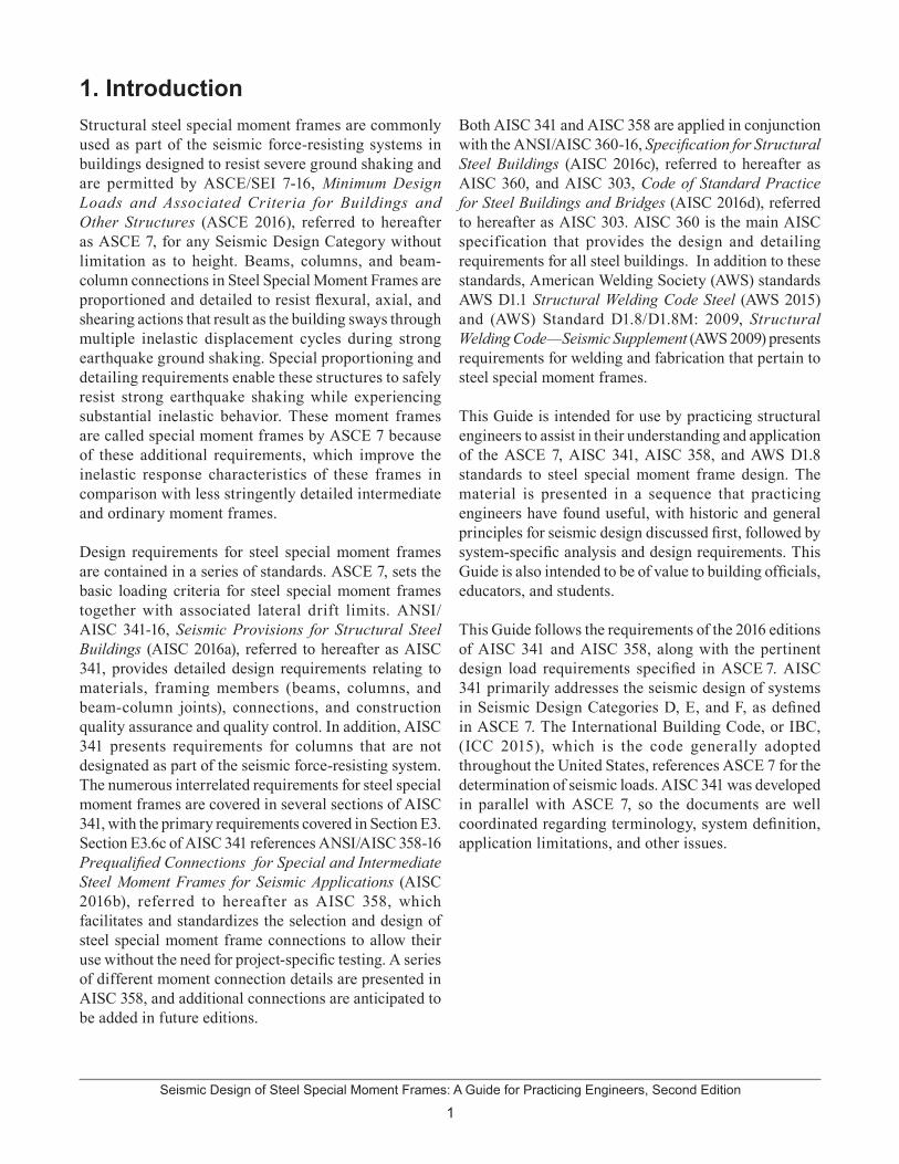
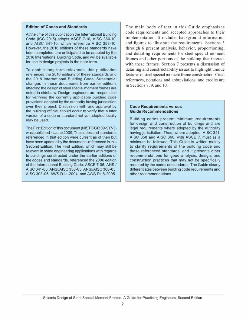
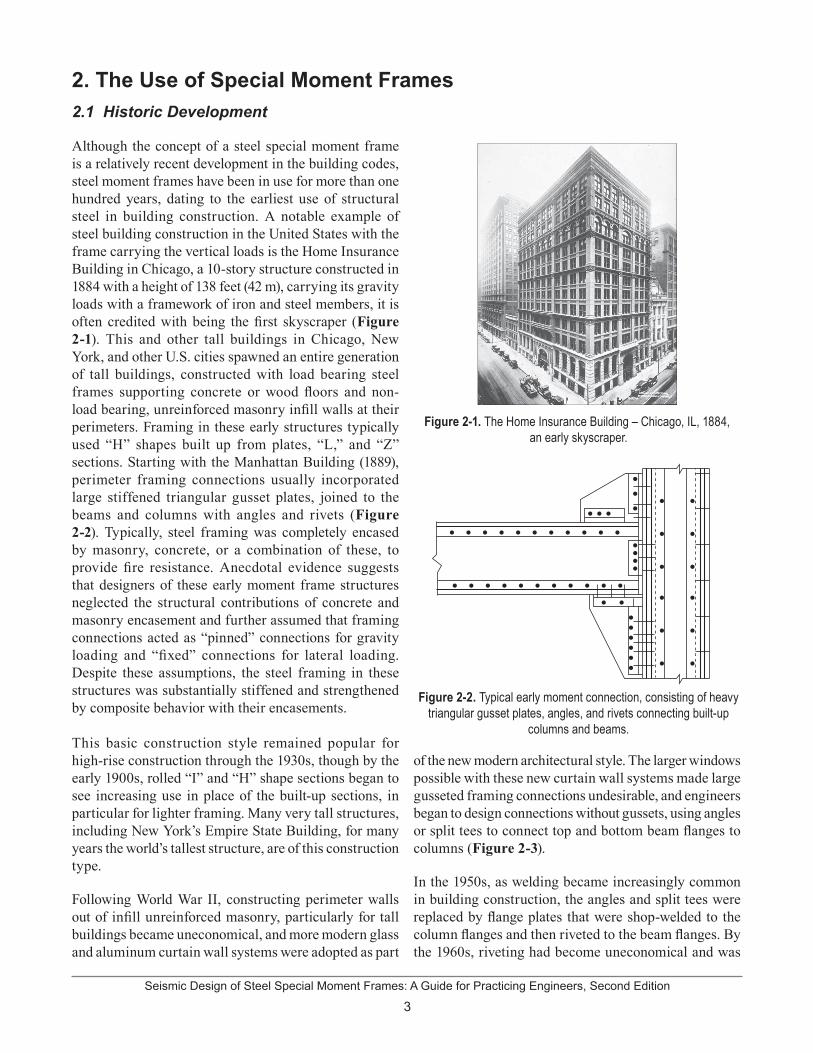
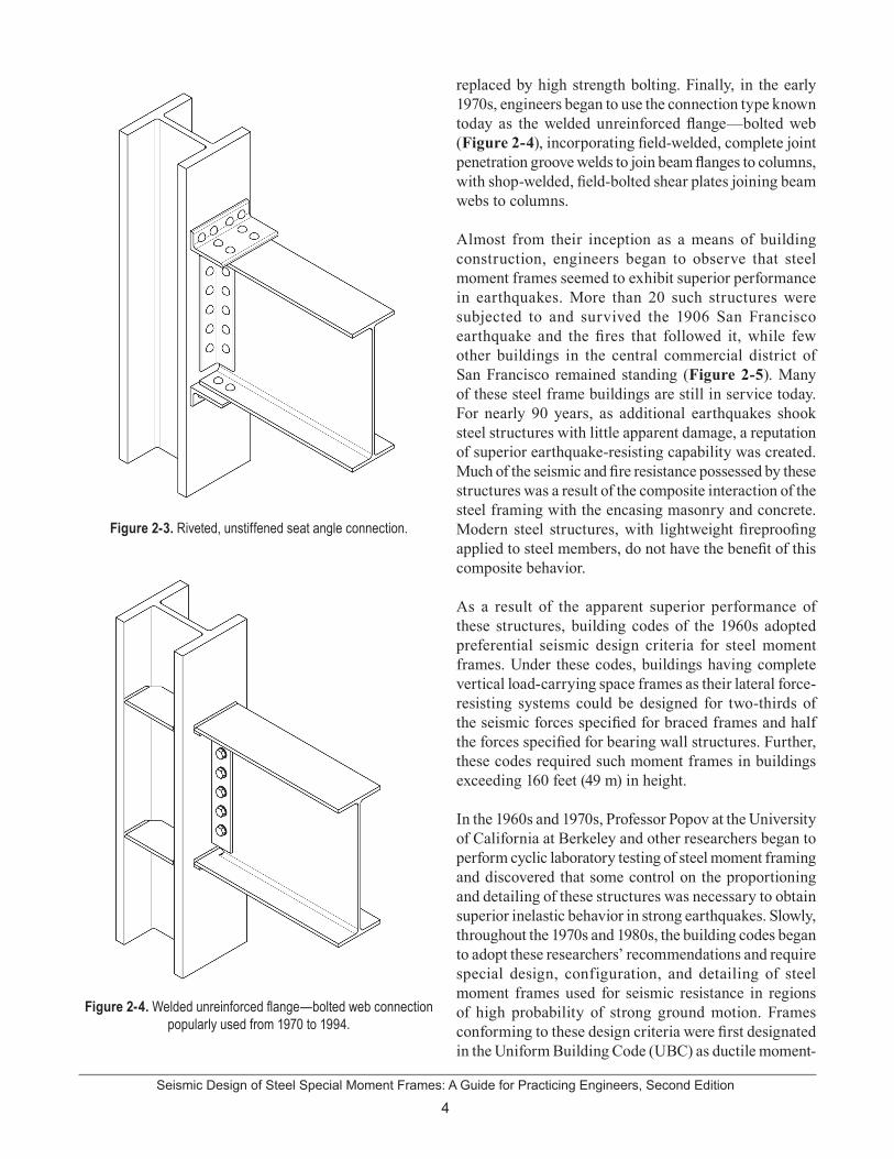
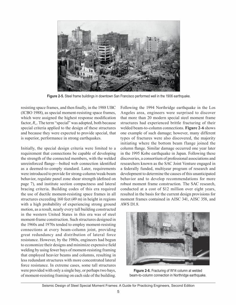
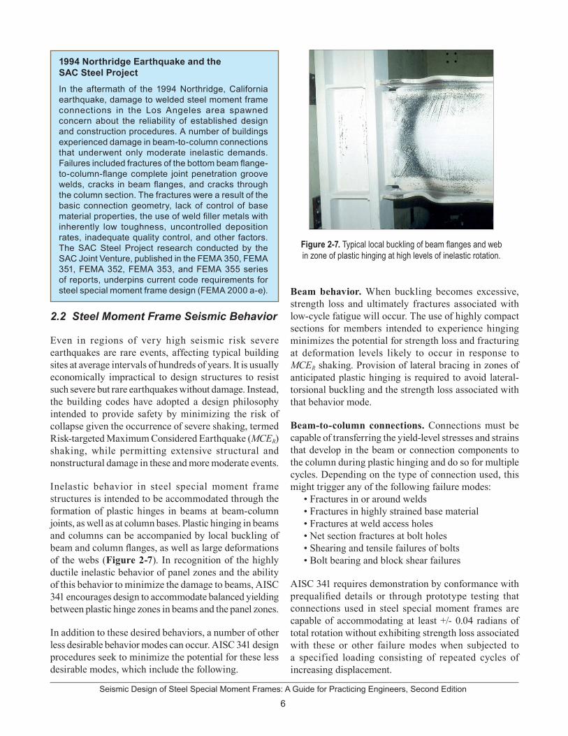
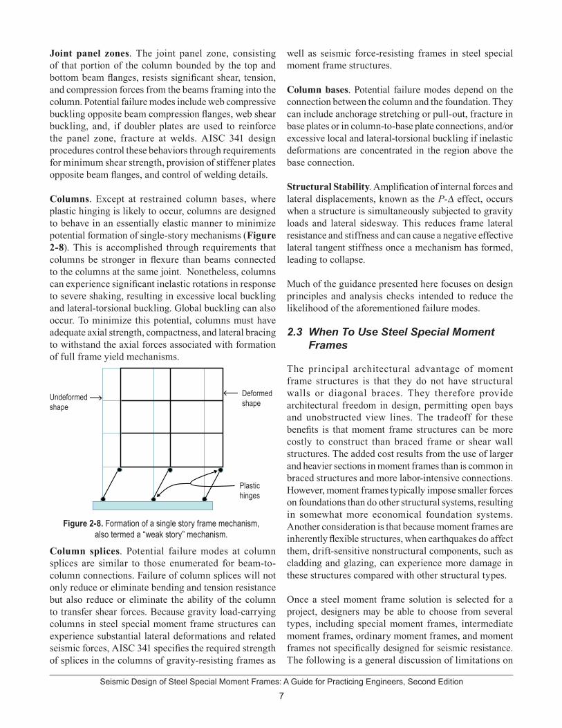
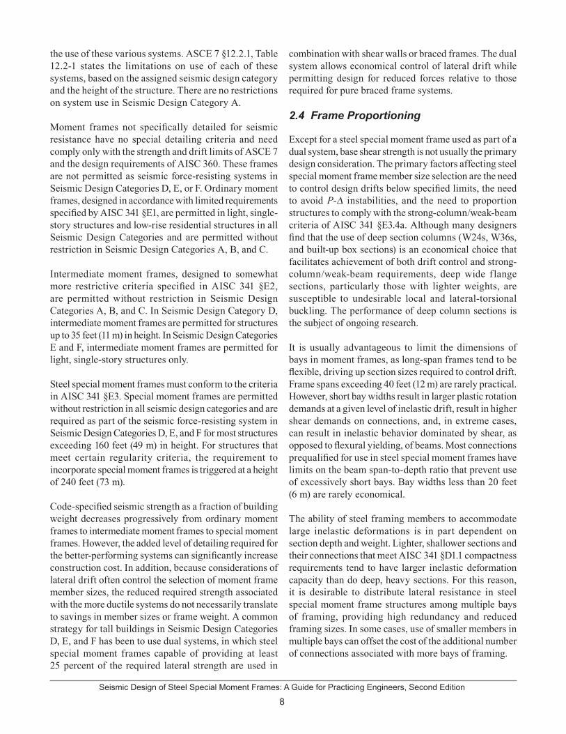
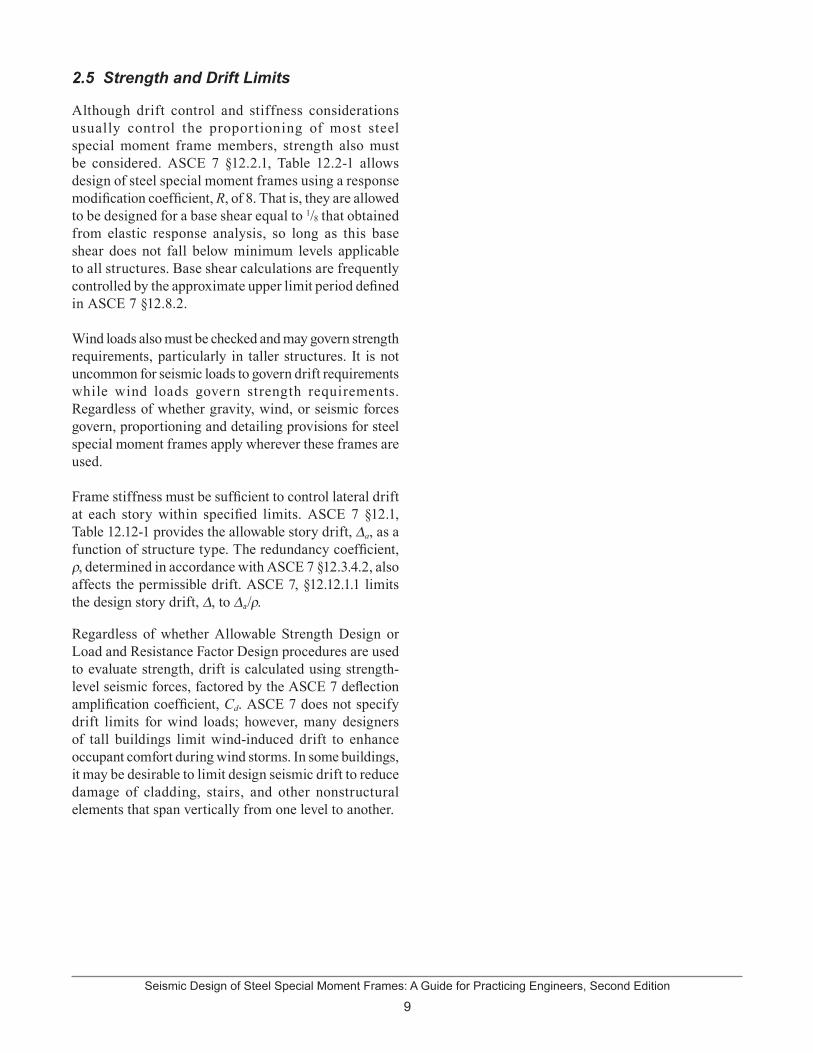
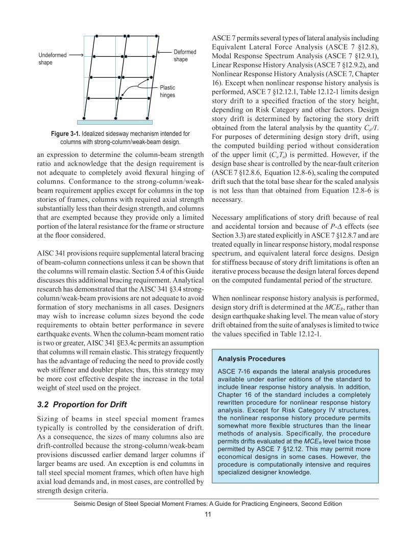
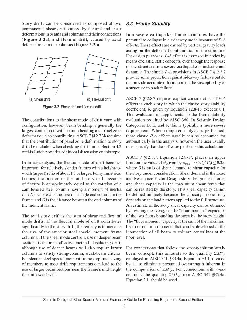
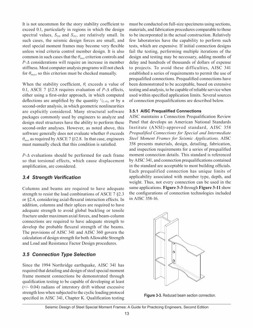
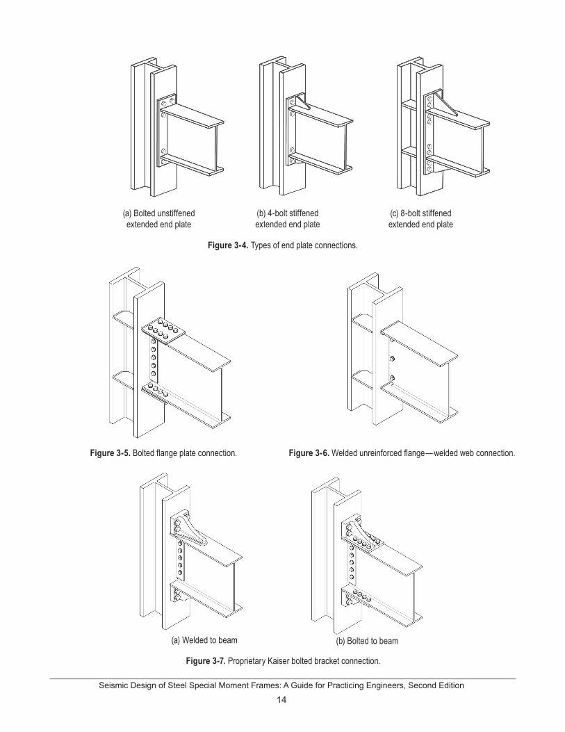
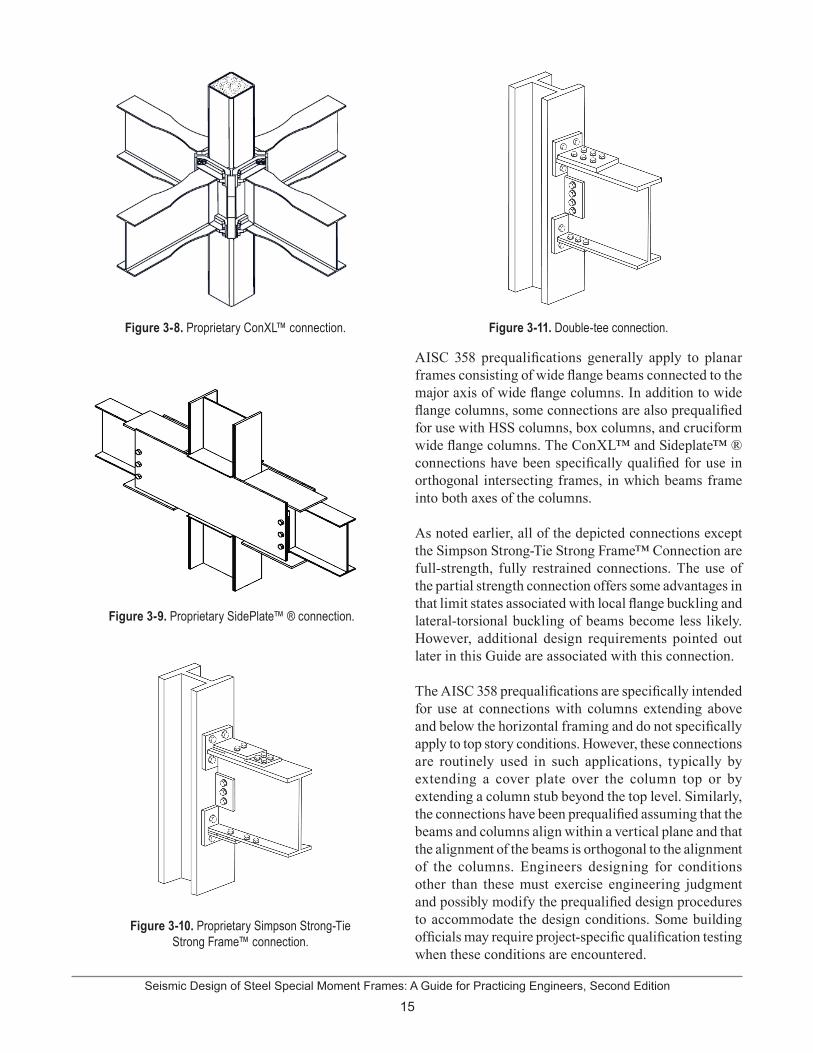
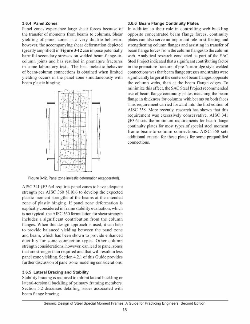
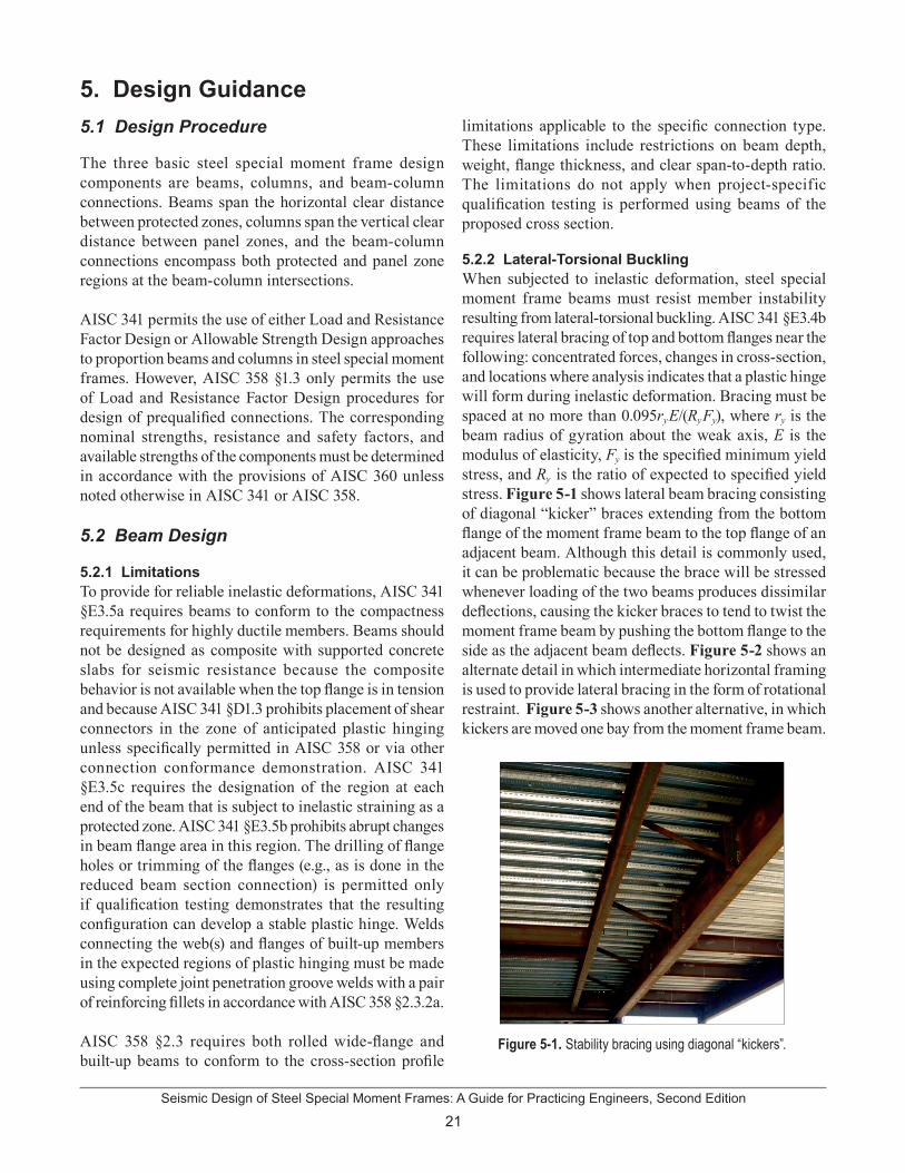
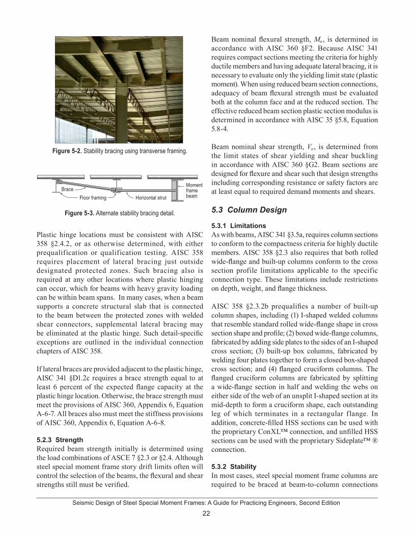
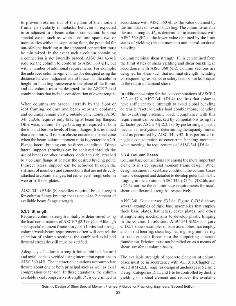
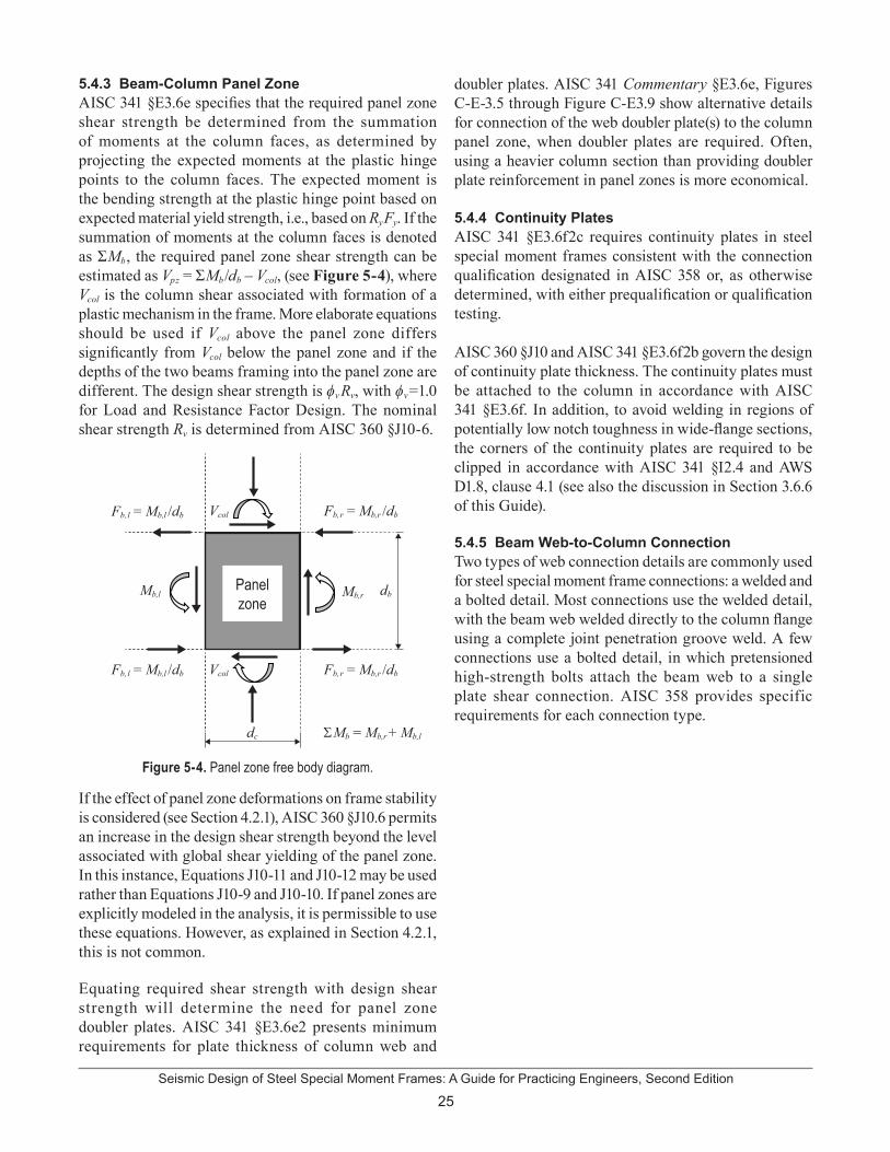
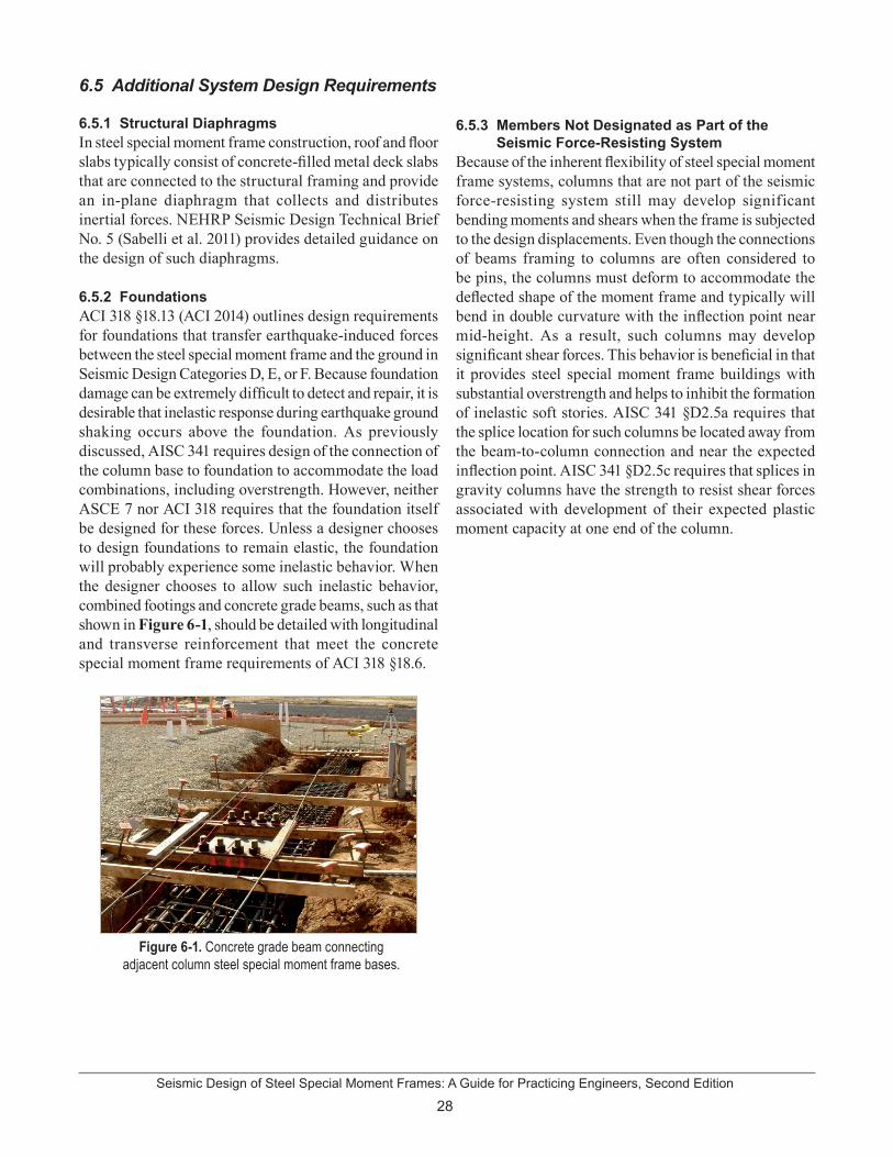
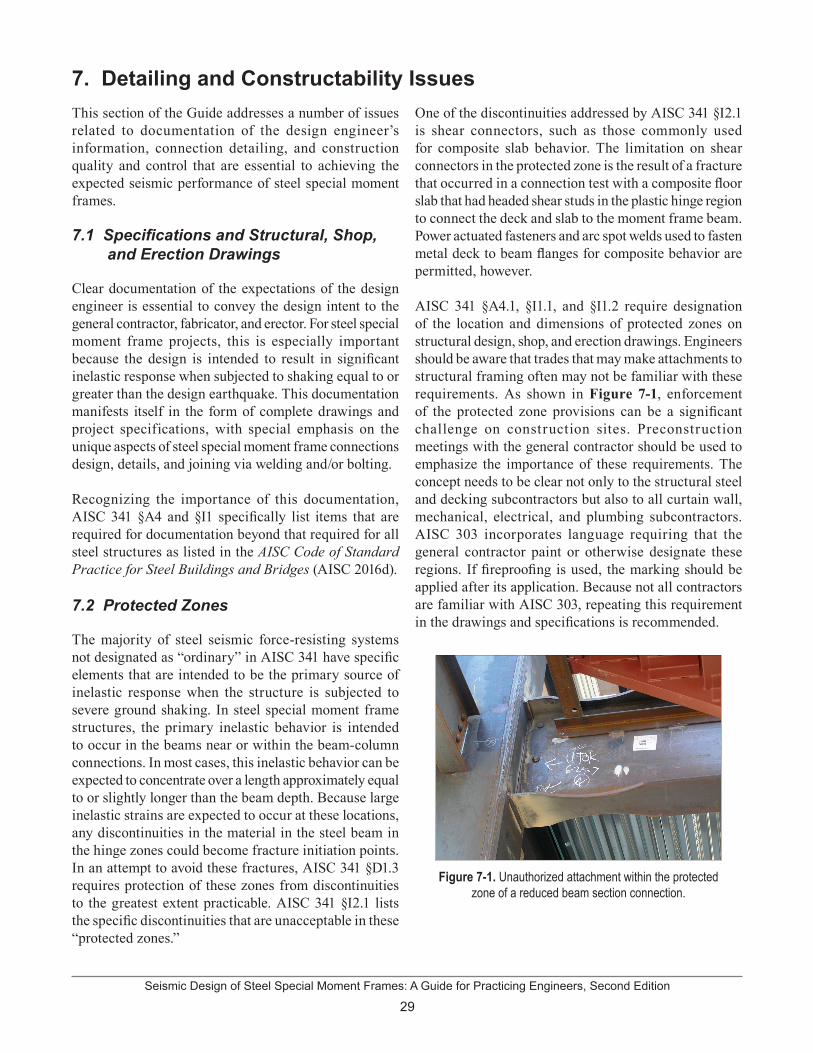
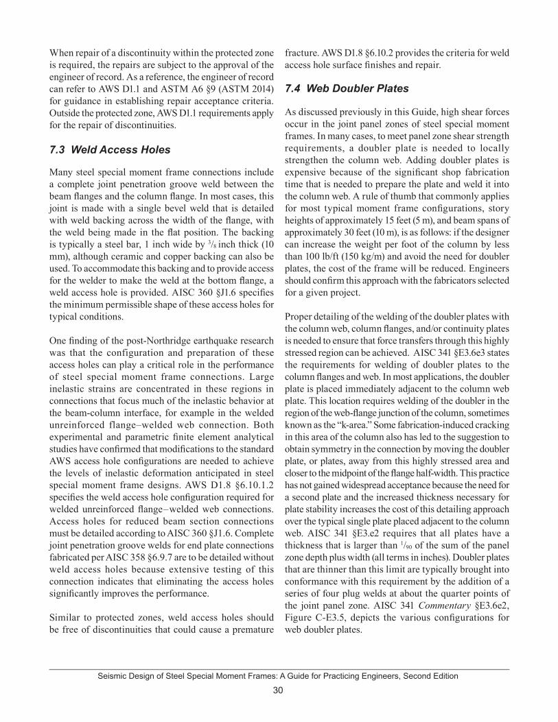
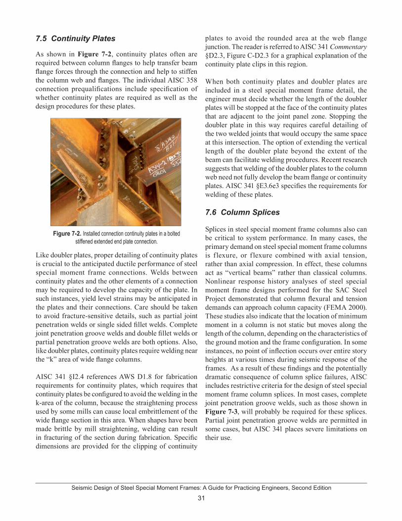
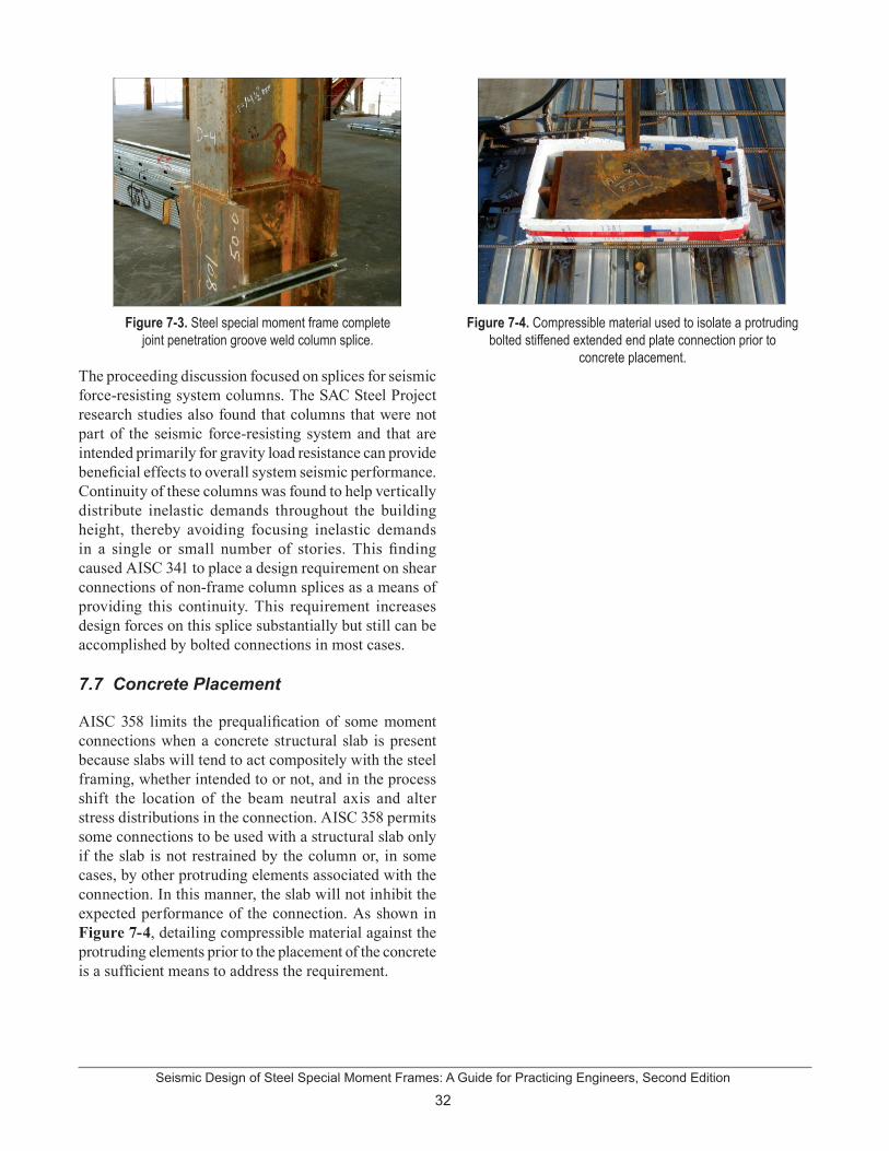


![Nonlinear Static Analysis to Assess Seismic Performance ... · (NEHRP) guidelines for the seismic rehabilitation of buildings [68]. It require realistic values of the effective cracked](https://static.documents.pub/doc/80x56/5fcb1299db4e5462ec6f6178/nonlinear-static-analysis-to-assess-seismic-performance-nehrp-guidelines-for.jpg)


