Advantages gained from the use of a geomembrane waterproofing system on RCC dams: experiences from Australia G.L. Vaschetti, C.A. Verani, & J.W. Cowland CARPI TECH, Via Passeggiata 1, 6828 Balerna, Switzerland. Geomembranes are an established technique for long-term waterproofing of hydraulic structures including all types of dams, canals, tunnels and reservoirs. Three construction projects are presented that feature unique waterproofing solutions leading to faster construction programmes and granting safer and longer service life at lower costs: The 35 m high Paradise Dam (aka Burnett River), Australia's largest volume Roller Compacted Concrete (RCC) dam waterproofed using a PolyVinylChloride (PVC) geomembrane sandwiched between prefabricated concrete panels and the RCC itself; The 50 m high multipurpose Meander Dam in Tasmania, designed as a RCC dam of the low cementitious content type whose imperviousness is provided by a PVC geomembrane installed in exposed position and mechanically anchored to the upstream face of the dam; And the Eidsvold Weir, a 115 m long 15.45 m high RCC structure used for water supply, waterproofed using an external PVC waterstop installed on the upstream face and able to accommodate the expected movements at the joints. The paper will outline the technical details, installation and performance of the geomembranes. Keywords: Geomembranes, waterproofing, Roller Compacted Concrete (RCC) dams, PolyVinylChloride (PVC), external waterstop. Introduction The popularity gained by RCC dams over the past decade has been largely due to benefits such as the design, which is simpler than for conventional concrete dams, and the construction procedures, which allow faster placement and therefore reduced construction time. RCC dams have proven over time to be a technically sound and financially valuable solution. Due to construction procedures and materials, however, RCC dams have a higher risk of water infiltration from the reservoir that may affect the overall stability of the structure. The main causes of infiltration are the horizontal lift joints, induced or random vertical joints, the contact area between the RCC and the conventional concrete, and the higher permeability of the concrete mix itself. The control of permeability in RCC dams can be achieved by intervening on the body of the dam (mass concrete permeability) or by intervening on the upstream face (upstream face permeability) or a combination of the two. Whilst it can be argued that low and high cementitious RCC is impermeable, the permeability of the interface lift joints can be significant. As stated by an RCC dam expert one seeping lift joint is sufficient to affect the stability and uplift of the dam. This suggests that both low and high cementitious mix designs require a water barrier on the upstream face. In RCC dams, cement quantity typically exceeds strength requirements to improve lift joint impermeability. By introducing a water barrier at the upstream face, the cement content can be reduced considerably. This is achieved by separating the waterproofing and static functions and introducing a separate watertight element on the upstream face. Among available upstream water barriers, the geomembrane solution is now an accepted technique. This solution is currently available in two configurations, both outlined in this paper: The covered solution, also known as the Winchester system, from the name of the US dam where it was first adopted in 1984, adopts a synthetic geomembrane system embedded in the precast facing (Figure 1). Figure 1. Illustration of the Winchester covered geocomposite system. The exposed solution adopts a drained synthetic geomembrane system mechanically fixed to the upstream face of the dam (Figure 2). ANCOLD Proceedings of Technical Groups
Transcript
Advantages gained from the use of a geomembrane waterproofing system on RCC dams: experiences from Australia
G.L. Vaschetti, C.A. Verani, & J.W. Cowland
CARPI TECH, Via Passeggiata 1, 6828 Balerna, Switzerland.
Geomembranes are an established technique for long-term waterproofing of hydraulic structures including all types of dams, canals, tunnels and reservoirs.
Three construction projects are presented that feature unique waterproofing solutions leading to faster construction programmes and granting safer and longer service life at lower costs: The 35 m high Paradise Dam (aka Burnett River), Australia's largest volume Roller Compacted Concrete (RCC) dam waterproofed using a PolyVinylChloride (PVC) geomembrane sandwiched between prefabricated concrete panels and the RCC itself; The 50 m high multipurpose Meander Dam in Tasmania, designed as a RCC dam of the low cementitious content type whose imperviousness is provided by a PVC geomembrane installed in exposed position and mechanically anchored to the upstream face of the dam; And the Eidsvold Weir, a 115 m long 15.45 m high RCC structure used for water supply, waterproofed using an external PVC waterstop installed on the upstream face and able to accommodate the expected movements at the joints.
The paper will outline the technical details, installation and performance of the geomembranes.
The popularity gained by RCC dams over the past decade has been largely due to benefits such as the design, which is simpler than for conventional concrete dams, and the construction procedures, which allow faster placement and therefore reduced construction time. RCC dams have proven over time to be a technically sound and financially valuable solution.
Due to construction procedures and materials, however, RCC dams have a higher risk of water infiltration from the reservoir that may affect the overall stability of the structure. The main causes of infiltration are the horizontal lift joints, induced or random vertical joints, the contact area between the RCC and the conventional concrete, and the higher permeability of the concrete mix itself.
The control of permeability in RCC dams can be achieved by intervening on the body of the dam (mass concrete permeability) or by intervening on the upstream face (upstream face permeability) or a combination of the two.
Whilst it can be argued that low and high cementitious RCC is impermeable, the permeability of the interface lift joints can be significant. As stated by an RCC dam expert one seeping lift joint is sufficient to affect the stability and uplift of the dam. This suggests that both low and high cementitious mix designs require a water barrier on the upstream face. In RCC dams, cement quantity typically exceeds strength requirements to improve lift joint impermeability. By introducing a water barrier at the upstream face, the cement content can be reduced considerably. This is achieved by separating the
waterproofing and static functions and introducing a separate watertight element on the upstream face.
Among available upstream water barriers, the geomembrane solution is now an accepted technique. This solution is currently available in two configurations, both outlined in this paper:
The covered solution, also known as the Winchester system, from the name of the US dam where it was first adopted in 1984, adopts a synthetic geomembrane system embedded in the precast facing (Figure 1).
Figure 1. Illustration of the Winchester covered geocomposite system. The exposed solution adopts a drained synthetic
geomembrane system mechanically fixed to the upstream face of the dam (Figure 2).
ANCOLD Proceedings of Technical Groups
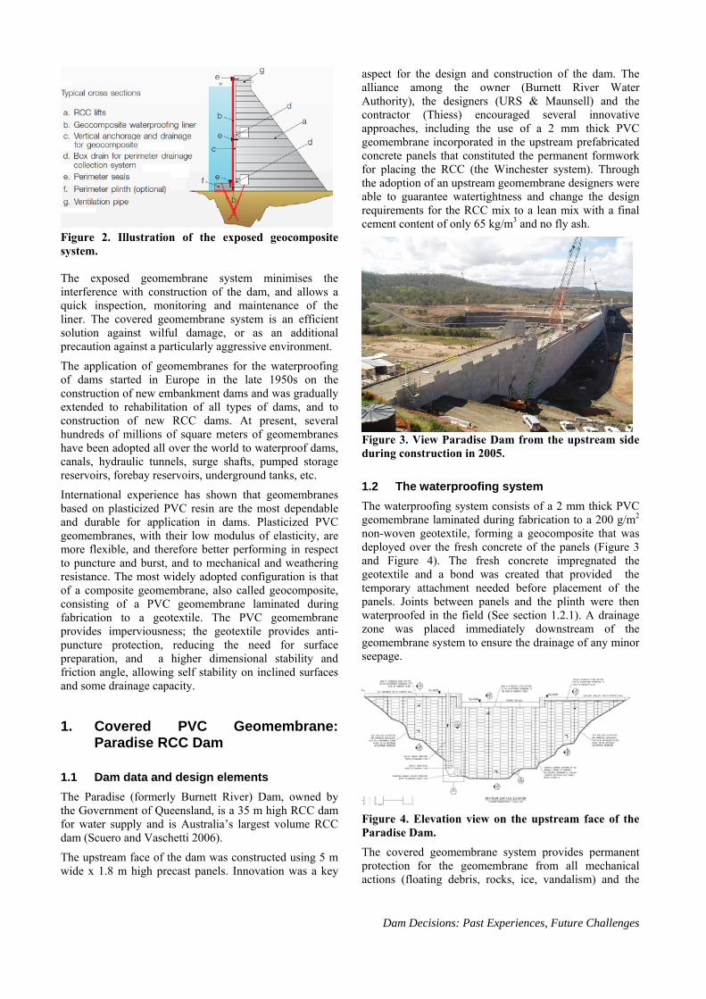
Figure 2. Illustration of the exposed geocomposite system. The exposed geomembrane system minimises the interference with construction of the dam, and allows a quick inspection, monitoring and maintenance of the liner. The covered geomembrane system is an efficient solution against wilful damage, or as an additional precaution against a particularly aggressive environment.
The application of geomembranes for the waterproofing of dams started in Europe in the late 1950s on the construction of new embankment dams and was gradually extended to rehabilitation of all types of dams, and to construction of new RCC dams. At present, several hundreds of millions of square meters of geomembranes have been adopted all over the world to waterproof dams, canals, hydraulic tunnels, surge shafts, pumped storage reservoirs, forebay reservoirs, underground tanks, etc.
International experience has shown that geomembranes based on plasticized PVC resin are the most dependable and durable for application in dams. Plasticized PVC geomembranes, with their low modulus of elasticity, are more flexible, and therefore better performing in respect to puncture and burst, and to mechanical and weathering resistance. The most widely adopted configuration is that of a composite geomembrane, also called geocomposite, consisting of a PVC geomembrane laminated during fabrication to a geotextile. The PVC geomembrane provides imperviousness; the geotextile provides anti-puncture protection, reducing the need for surface preparation, and a higher dimensional stability and friction angle, allowing self stability on inclined surfaces and some drainage capacity.
1. Covered PVC Geomembrane: Paradise RCC Dam
1.1 Dam data and design elements
The Paradise (formerly Burnett River) Dam, owned by the Government of Queensland, is a 35 m high RCC dam for water supply and is Australia’s largest volume RCC dam (Scuero and Vaschetti 2006).
The upstream face of the dam was constructed using 5 m wide x 1.8 m high precast panels. Innovation was a key
aspect for the design and construction of the dam. The alliance among the owner (Burnett River Water Authority), the designers (URS & Maunsell) and the contractor (Thiess) encouraged several innovative approaches, including the use of a 2 mm thick PVC geomembrane incorporated in the upstream prefabricated concrete panels that constituted the permanent formwork for placing the RCC (the Winchester system). Through the adoption of an upstream geomembrane designers were able to guarantee watertightness and change the design requirements for the RCC mix to a lean mix with a final cement content of only 65 kg/m3 and no fly ash.
Figure 3. View Paradise Dam from the upstream side during construction in 2005.
1.2 The waterproofing system
The waterproofing system consists of a 2 mm thick PVC geomembrane laminated during fabrication to a 200 g/m2 non-woven geotextile, forming a geocomposite that was deployed over the fresh concrete of the panels (Figure 3 and Figure 4). The fresh concrete impregnated the geotextile and a bond was created that provided the temporary attachment needed before placement of the panels. Joints between panels and the plinth were then waterproofed in the field (See section 1.2.1). A drainage zone was placed immediately downstream of the geomembrane system to ensure the drainage of any minor seepage.
Figure 4. Elevation view on the upstream face of the Paradise Dam.
The covered geomembrane system provides permanent protection for the geomembrane from all mechanical actions (floating debris, rocks, ice, vandalism) and the
Dam Decisions: Past Experiences, Future Challenges
effects of an aggressive climate. Stringent Quality Control was implemented to assure that the geomembrane was not damaged during RCC construction related activities.
1.2.1 Joints and footing
A strip of geomembrane was welded between panels, both horizontally and vertically, to provide waterproofing continuity across joints. Where the panels meet the plinth a strip of geomembrane was attached to the downstream face of the panel footing and welded to a longitudinal waterstop cast into the grout cap (Figure 5).
Figure 5. View on the inside face of the panels, showing the PVC geomembrane embedded in the grout cap.
1.2.2 Primary spillway
At the primary (central) spillway section, the geomembrane extends up to El. 65.7, which is the top of the concrete precast panels and where the conventional concrete crest form commences. Conventional concrete was cast up against the geomembrane between El. 65.4 and 65.7. A horizontal strip of geomembrane was welded to the upper part of the geomembrane on the panels, and then fully embedded into the conventional concrete cap by a minimum length of 300 mm.
To prevent water from flowing into the monolith joints from the conventional concrete crest a system of waterstops was welded to the top of the geomembrane and embedded across the joint over the entire “ogee” crest (Figure 6).
ANCOLD Proceedings of Technical Groups
Figure 6. View of the main spillway. 1.2.3 Abutments
At the right and left abutment sections, the geomembrane extends to El. 69.3, which corresponds to approximately the 1 in 2 year flood level. This provides an excellent upstream seal for a reasonable level above full supply level. However, when the reservoir level exceeds El. 69.3 it is important that there is no direct flow path to the drainage system or into the monolith joints. To achieve this a conventional concrete cap was cast along the top of the geomembrane at El. 69.3, which embeds the geomembrane by at least 300 mm to ensure an adequate seal at the top of the geomembrane to avoid a flow connection to the drainage system.
1.2.4 Drainage system
A drainage system was provided behind the precast concrete panels on the upstream face of the dam. This drainage system was installed as installation of the precast panels and RCC construction progressed. The components of the drainage system included the following:
Bedding mix placed against the geotextile to ensure that the most upstream part of the RCC has a lower permeability ensuring that any leakage past the geomembrane flows along the drainage system rather than through the dam.
A 200 mm wide x 40 mm thick stripdrain placed horizontally at every panel height intercepted any leakage that got passed the geomembrane and carried that leakage to vertical slotted PVC pipes.
150 mm diameter vertical slotted, PVC pipes placed every 22.5 m at the monolith joints and mid span between these joints. These pipes were extended progressively to the crest to enable future clearing of the pipes. Outlets are provided to the downstream face.
1.3 Construction
Construction of the dam followed the sequence below:
Preparation for the perimeter seal at the heel of the dam. A PVC geomembrane sheet was embedded in the grout cap so that it extended horizontally in the body of the dam and constituted a horizontal barrier to upward migration of water seeping from the foundation (Figure 5).
Placement of the first rows of panels with the geomembrane side facing the dam body so that after construction the PVC geomembrane was “sandwiched” between the upstream concrete of the panels and the downstream RCC lifts. The shape of the panels allowed easy placement and interlocking (Figure 7).
Connection of adjoining panels along the entire perimeter through PVC geomembrane strips heat-welded to the geomembrane of the panels.
Connection of the panels to the steel bars that anchored them to the dam through watertight fittings (Figure 8).
Dam Decisions: Past Experiences, Future Challenges
igure 7. Erection of precast panels.
Placement of RCC. As the RCC lifts were placed, the anchor bars were embedded within them, thus securing the panels to the dam body (Figure 9).
F
Figure 8. Detail of anchoring rod.
Figure 9. View on the inside face of the panels,
struction proceeded with the placement of
concrete at the crest began.
showing the steel bars anchoring the panels to the dam body.
Consubsequent rows of panels, repeating the sequential steps described for the first row, until the dam body was completed, then construction of the traditional
The project was completed in 2005.
Figure 10. View of the upstream face as construction works proceeded.
PVC Geomembrane:
ivers and Water ly ose dam in the
0 m long central spillway at RL 402 m, a
e RCC
rting with
. Exposed 2Meander RCC Dam
2.1 Dam data and background
The Meander Dam, owned by the RSupp Commission, is a multi-purpnorthern part of Tasmania designed by Hydro Tasmania Consulting and GHD; the main contractor was McConnell Dowell.
The dam, 50 m high and 170 m long at the crest, has a primary 5secondary 60 m long spillway on the right abutment at RL 404.6 m, and a 60 m long left abutment at RL 406.9 m. Monolith joints were placed at 25 m horizontal spacing. The dam has a 0.45 m x 0.35 m upstream plinth, a grout curtain with primary holes 1.75 m downstream of the upstream face, a 1.8 m x 2.7 m inspection gallery, and a 3 m wide precast outlet tower (Gibson et al. 2008).
The dam was designed as an all-RCC gravity dam of the low cementitious content type, built placing thagainst upstream precast concrete panels used as permanent formwork (Figure 11), with bedding mix placed adjacent to the panels. The waterproofing geomembrane was placed over the outside of the panels and not embedded in them as at Paradise Dam.
The panels were 5 m wide, 1.8 m high and 100 mm thick and the design for the system was self suppoadjacent panels offset by half the panel height.
ANCOLD Proceedings of Technical Groups
Figure 11. View of the upstream face of Meander Dam during erection of the precast panels.
The Meander Dam designers adopted the same philosophy adopted at Burnett River Dam, i.e. of separating the watertight function, provided by an upstream impervious geomembrane, from the static function, provided by the concrete. This philosophy allowed the use of a lean cement mix for the dam: the selected cement content was 70 kg/m3.
2.2 The waterproofing system
ce placing of the CC had been completed. The waterproofing
ultraviolet light preferred to an
(there were
g and draining system
slack areas and folds that are ion of stress that can be f the geomembrane. The
The imperviousness of the dam is provided by an exposed geomembrane which was mechanically attached to the
pstream face of the precast panels onuRgeomembrane covers the whole surface of the upstream face, with the exclusion of the intake tower.
Tender Specifications allowed for two types of geomembrane: Polyvinylchloride (PVC) or High Density Polyethylene (HDPE), requiring evidence that the proposed geomembrane had a durability replacement life of at least 30 years when exposed toand/or water. A PVC geomembrane was HDPE geomembrane because of the number of successful references in waterproofing of dams. Exposed PVC has been successfully used on 90 large dams of all types, up to 188 m high, since 1979, while there is no evidence of a successful installation of an exposed HDPE geomembranes on the upstream face of concrete dams. PVC can better adapt to an irregular subgradesignificant offsets between panels) and better follows the geometry of the dam. Welds are easier and more reliable, tensile properties grant good performance in case of movement between monoliths, and longevity in dam applications is proven. Very importantly, PVC has a low coefficient of thermal expansion.
The selected material was a 2.5 mm thick PVC geomembrane laminated during fabrication to a 500 g/m2 anti-puncture geotextile.
2.2.1 Face anchorage
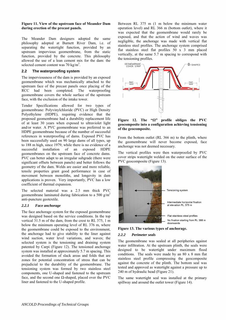
The face anchorage system for the exposed geomembrane was designed based on the service conditions. In the top vertical 31.5 m of the dam, from the crest to RL 375, 1 m below the minimum operating level of RL 376 m, where the geomembrane could be exposed to the environment, the anchorage had to give stability to the liner against wind suction, water level variations, and waves; the selected system is the tensioninpatented by Carpi (Figure 12). The tensioned anchorage system was installed at approximately 5.7 m spacing. This avoided the formation ofzones for potential concentratprejudicial to the durability otensioning system was formed by two stainless steel components, one U-shaped and fastened to the upstream face, and the second one Ω-shaped, placed over the PVC liner and fastened to the U-shaped profile.
Between RL 375 m (1 m below the minimum water operation level) and RL 366 m (bottom outlet), where it was expected that the geomembrane would rarely be exposed, and that the action of wind and waves was negligible, the anchorage was made with vertical flat stainless steel profiles. The anchorage system comprised flat stainless steel flat profiles 50 x 3 mm placed vertically, at the same 5.7 m spacing to correspond with the tensioning profiles.
Figure 12. The “Ω” profile obliges the PVC geocomposite into a configuration achieving tensioning of the geocomposite. From the bottom outlet (RL 366 m) to the plinth, where the geomembrane will never become exposed, face anchorage was not deemed necessary.
The vertical profiles were then waterproofed by PVC cover strips watertight welded on the outer surface of the PVC geocomposite (Figure 13).
Figure 13. The various types of anchorage.
2.2.2 Perimeter seals
The geomembrane was sealed at all peripheries against water infiltration. At the upstream plinth, the seals were designed to be watertight under maximum flood conditions. The seals were made by an 80 x 8 mm flat stainless steel profile compressing the geocomposite against the concrete of the plinth. The bottom seal was tested and approved as watertight against a pressure up to 240 m of hydraulic head (Figure 21).
he primary spillway and around the outlet tower (Figure 14). The same watertight seal was installed at t
Dam Decisions: Past Experiences, Future Challenges
p dary spillway and at the left
ided behind the
herwise
The to seal at the seconabutment, considering that they would be submerged only in exceptional cases and under a limited head was designed to be watertight only against rain water. The seal was made by a 50 x 3 mm flat stainless steel profile, fastened to the panels with impact anchors at 0.20 m spacing.
2.2.3 Drainage system
A drainage system was provgeomembrane to drain any minor leakage. The drainage system prevents pressure build up that could otcause geomembrane or panel failure during reservoir drawdown, and also allows monitoring the efficiency of the geomembrane liner by measuring the drained flow. The system includes a face drainage layer, vertical drains, horizontal and peripheral drainage collection zones, and transverse discharge conduits to the gallery and to downstream.
Figure 14. Upstream view of the waterproofing system.
2.2.4 Joints between panels and monoliths
To support the PVC liner on the joints between monoliths and between panels an additional layer of the same PVC liner was installed to span the gaps under full loading and therefore there was no need to fill the joints (Figure 15).
Figure 15. Additional sacrificial layer of geomembrane spanning across a joint providing support to the main geocomposite.
2.3 Construction
Access to the panels for installation of the geomembrane system was made by suspended platforms from a swing stage scaffold over the length of the primary spillway,
with a monorail system used on the left and right abutments.
2.3.1 Surface preparation
To protect the PVC liner against possible puncture by the 7 to 10 mm offsets between panels under full hydraulic loading, a 1000 g/m2 geotextile was installed over the panels. The geotextile allowed the geomembrane to span the gaps without the need to fill the joints between panels. The geotextile also provided support to the PVC liner on the joints between monoliths (Figure 16).
m, the anti-puncture geotextile, and the eotextile backing the PVC geomembrane), drainage of
he following components:
drainage geonet placed
ater will travel by gravity in (geotextile, gap between
2.3.2 Drainage system
Besides the face drainage layer (the gap allowed by the anchorage systegthe system is provided by t
Hollow tensioning profiles at 5.75 m centres immediately behind the geomembrane;
Embedded horizontal drainage collection zones made with porous concrete immediately behind the precast panels at elevations RL 396 m and RL 391 m, and upstream of the gallery;
Bands of a highly transmissiveon the panels in front of the horizontal drainage zones, and running along the plinth at the left and right abutments (Figure 17); and
Transverse discharge cross drains at 10m centres draining leakage from the horizontal drainage zones to the gallery or downstream face.
Seepage or condensation wthe various componentsgeotextile and concrete panels, vertical tensioning profiles), to reach the collection system (bands of drainage geonet), and then discharge into the gallery.
Figure 16. Installation of the anti-puncture geotextile on the lower part of the panels.
Figure 17. The black band of geonet along the plinth t the right abutment collects a
w
ANCOLD Proceedings of Technical Groups
and conveys drained ater to the discharge points.
2.3.3 Waterproofing liner
Installation of the waterproofing system was staged in two horizontal sections. In the first phase the waterproofing system was installed in the bottom section, from approximately RL 375 m down to the plinth, to allow early impoundment. In this section the PVC sheets were anchored at RL 375 m by a fixing comprising a 50 x 3 mm stainless steel flat profile, fastened to the panels with impact anchors at 0.20 m spacing, and were then rolled down over the panels (Figure 18).
the bottom section, and m, thus waterproofing also
In the second phase the waterproofing system was installed from crest down RL 375 m (Figure 19). The PVC sheets waterproofing the top section overlapped the PVC sheets already installed inwere watertight welded to thethe intermediate fixing at RL 375 m (Figure 20).
Figure 18. Installation of the PVC sheets (the grey material) on the anti-puncture geotextile in thpart of the dam.
e lower
Figure 19. Installation and anchorage of the PVC sheets in the top part of the dam, at the primary spillway section.
Figure 20. View of the completed geomembrane system installation.
2.3.4 Face anchorage
Once the geotextile had been locally removed, adjacent sheets of geocomposite were welded together and anchored to the dam face by means of Carpi patented vertical tensioning profiles.
The lower U-shaped profiles were fastened to the panels with chemical anchors. The two ends of adjacent sheets of geocomposite were then pulled over the profiles so that they overlapped sufficiently to enable the upper -shaped profile to compress the two layers and tension the geocomposite, lying between vertically placed tensioning
ed over the tensioning profile to
t seal.
profiles, transversally. The two profiles were secured together with a connector. A PVC geomembrane cover strip was then weldachieve full watertightness.
2.3.5 Perimeter seals
A layer of resin, rubber gaskets and splice plates (Figure 21) allow the regular and adequate compression that is necessary to achieve a perfec
Figure 21. The seal over the primary spillway, along the upstream plinth, and at the outlet tower is watertight against the water pressure, and was tested at 240 m head.
The project was completed in late 2007 (Figure 22) and initial seepage data are encouraging (See section 4). Based on the performance of geomembrane systems on dams with a lean cement mix, very low seepage and no maintenance are expected in the future.
Figure 22. Meander dam impounding in November 2007.
3
Dam Decisions: Past Experiences, Future Challenges
. Exposed PVC Geomembrane as
t of Eidsvold in Queensland, is a 115 m long, 15.45 m high RCC dam owned by Burnett Water Pty Ltd. and used for water supply (Figure 23).
external waterstop: Eidsvold RCC Main Weir
Eidsvold Main Weir, located on the Burnett River approximately 5 kilometres north-wes
Figure 23. View from the upstream face of the
ent was expected at three of the ertical construction joints between the monoliths, a
waterproofing system (PVC geomembrane) was installed as an external waterstop on the upstream face in correspondence with the three joints to ensure safe operation of the dam (Figure 24). The external waterstop was designed to be able to largely accommodate the expected movements of the joints in three directions, including opening, shear, and rotation. The new external waterstop was also connected to the existing rearguard waterstop at the heel of the joints (Figure 25) to provide continuity in the system.
3.1.1 Vertical joints
The new external waterstop was composed of three independent layers of synthetic materials, positioned over the upstream concrete face and sealing the joints from the top of the nib wall or from the top of the ogee down to the heel (Figure 24). The first two layers have the function of supporting the third layer, the new waterproofing liner, in case of maximum opening of joint and maximum water head. The support layers comprised: two layers of PVC geocomposite consisting of a 2.5 mm thick impervious PVC geomembrane, heat-coupled during fabrication to a 500 g/m² polyester geotextile. Each layer was 520 mm wide and anchored to the dam body by 8 mm diameter
e waterproofing geocomposite
waterproofing PVC
its imperviousness
mmodate e expected movements of the joints.
Eidsvold Weir prior to commencement of the waterproofing activities.
3.1 Waterproofing system
Since major movemv
impact anchors, placed on each side of the geocomposite at 30 cm centres. The function of the supporting layers was to provide additional mechanical support and reduce
e friction angle with ththacross the joint (Figure 26).
The waterproofing liner: one layer ofgeocomposite consisting of a 2.5 mm thick impervious PVC geomembrane, heat-coupled during extrusion to a 500 g/m² polyester geotextile. The PVC geocomposite is 52 cm wide, and can elongate over its entire width to follow the movements of the joint. The PVC geocomposite will largely maintainunder the expected service conditions, as a theoretical 1.15 m joint opening will be required for the geocomposite to break. The elongation properties, the width of the geocomposite strips, and the fact that the geocomposite was anchored only at the periphery, will allowing the external waterstop to largely accoth
Figure 24. Sketch illustrating the extent of the exposed geomembrane system.
ANCOLD Proceedings of Technical Groups
Figure 25. Detail C from Figure 24 illustrating the connection of the geocomposite to the waterstop at the foot of the dam.
3.1.2 Perimeter seal
The external waterstop was sealed at the perimeter by a watertight seal of the compression type made with flat stainless steel profiles, 75 x 8 mm. The profiles were anchored to the curbs of the RCC by means of chemical anchors at approximately 150 mm spacing (Figure 26). The watertightness of the anchorage is inherently achieved through compression of the geocomposite against the concrete face. The seal is of the same type
.1.3 Connection at the heel
A watertight connection was achieved between the geocomposite waterproofing the vertical joints and the rearguard waterstop embedded in the dam body and coming out from the RCC layers at the heel of the dam (Figure 26). The connection was made by watertight welding the backside of the waterproofing geocomposite, after removal of the geotextile, to the upper side of the rearguard PVC waterstop (Figure 27) and maintaining the joint in compression through a seal the same as that used
iew of the works on the upstream face an be seen in Figure 29. The project was completed in
adopted at Meander Dam. 3
at the periphery.
A view of a completed joint waterstop can be seen in igure 28F
c, and a v
2004.
Figure 26. View of the support layer at the foot of the vertical joint. The waterstop can be seen emerging from the RCC body.
Figure 27. Arrangement of the connection to the waterstop at the heal.
Dam Decisions: Past Experiences, Future Challenges
Figure 28. View of a completed joint waterstop.
References
Gibson, G., Griggs, T., Scuero, A. and Vaschetti, G. 2008. Meander RCC dam in Tasmania. Proceedings, 2nd International Symposium on Water Resources and Renewable Energy Development in Asia, Danang, Vietnam.
Figure 29. View of the corner waterstop.
Herweynen R. 2006. Burnett RCC dam – An innovative approach to floods. Proceedings ICOLD 22nd International Congress, Barcelona, Spain.
Scuero, A. and Vaschetti, G. 2006. Geomembrane experience on dams and canals in South East Asia. Proceedings, 1st International Symposium Water Resources and Renewable Energy Development in Asia, Bangkok, Thailand.
4 Performance and conclusions
At Paradise Dam, the designers reported the total estimated seepage at 65% impoundment to be less than 2 l/s, and the majority of this seepage was considered to be coming through the foundation rather than the geomembrane (Herweynen 2006).
At Meander Dam the use of precast units for upstream formwork, covered by an upstream exposed impervious geomembrane, allowed the use of a lean cement mix and also completion of the dam body in about 7 months. The installation of the waterproofing system was totally independent from the rest of the dam construction, and was completed in 6 weeks.
The exposed PVC geomembrane at Eidsvold Weir was installed in 2004 and has been maintaining imperviousness as expected.
n Australians all over the
rld, to have superior performance than concrete in nce
Geomembrane systems have been proven, irojects, as well as in now about 300 project
pworespect to seepage control, design life and maintenarequirements. They allow significant savings on other expensive components of the project and offer faster construction programmes.