DDC SECONDMENT REPORT Prepared By: Muhammad Fadhil Mohd Nawawi Table of Contents INTRODUCTION......................................................................2 MGKT TASKS........................................................................2 1 Intervention Shaft 1..........................................................2 1.1 Earthing Grid Design......................................................2 1.2 Drafting of Electrical and Mechanical ISD.................................2 2 Intervention Shaft 2..........................................................2 2.1 Electrical Supply Distribution and Protection.............................2 2.2 Earthing and Bonding......................................................3 2.3 Lightning Protection......................................................3 2.4 Cable Containment.........................................................3 2.5 Lighting Design...........................................................3 2.6 Mechanical Service Electrical Supply Single Line Diagram..................3 3 Escape Shaft 1................................................................3 3.1 Electrical ISD............................................................3 3.2 Drainage ISD..............................................................4 3.3 CSD and SEM drawings......................................................4 4 Tunnel........................................................................4 5 KL Sentral Station............................................................4 5.1 Cable Containment.........................................................4 5.2 Power Point Location......................................................4 5.3 ITB Schedule and Location.................................................4 5.4 Architectural Change......................................................4 6 Merdeka Station...............................................................5 7 Pasar Seni Station............................................................5 PDP TASKS.........................................................................5 1 Design Calculation of Elevated Stations.......................................5 2 Cable Containment Review......................................................5 APPENDICES........................................................................6 1 Intervention Shaft 1 Earthing Calculation.....................................6 2 IVS 2 Load Estimation and Analysis............................................8 3 IVS 2 Back of House Lighting Calculation.....................................10 4 IVS 2 Sketch.................................................................11 5 Tunnel Lighting Calculation..................................................18 Page 1 of 35
Transcript
DDC SECONDMENT REPORT Prepared By: Muhammad Fadhil Mohd Nawawi
Table of ContentsINTRODUCTION...................................................................................................................................................... 2
2.1 Electrical Supply Distribution and Protection..........................................................................................2
2.2 Earthing and Bonding..............................................................................................................................3
5.2 Power Point Location..............................................................................................................................4
5.3 ITB Schedule and Location.....................................................................................................................4
7 Pasar Seni Station...........................................................................................................................................5
8 Electrical Design Calculation of Elevated Station..........................................................................................24
Page 1 of 28
DDC Secondment Report
INTRODUCTION
This report outline the tasks and methodology of design learned in the period of secondment in AECOM’s office. The tasks essentially divided into two category, where the tasks made for AECOM’s client, MMC-Gamuda KVMRT (T) Sdn Bhd (MGKT) will be elaborated in section MGKT Tasks and also there’s tasks made for another AECOM’s client, MMC-Gamuda KVMRT (PDP) Sdn. Bhd (PDP) where will be elaborated in section PDP Tasks.
MGKT TASKS
To better categorise the task made MGKT, the sections are to correspond for each buildings that are related to the tasks made.
1 Intervention Shaft 1
Update Intervention Shaft 1 (IVS1) electrical design drawing based on changes on Architectural layout, design change by lead designer, DRR request by MGKT and conformance to specifications.
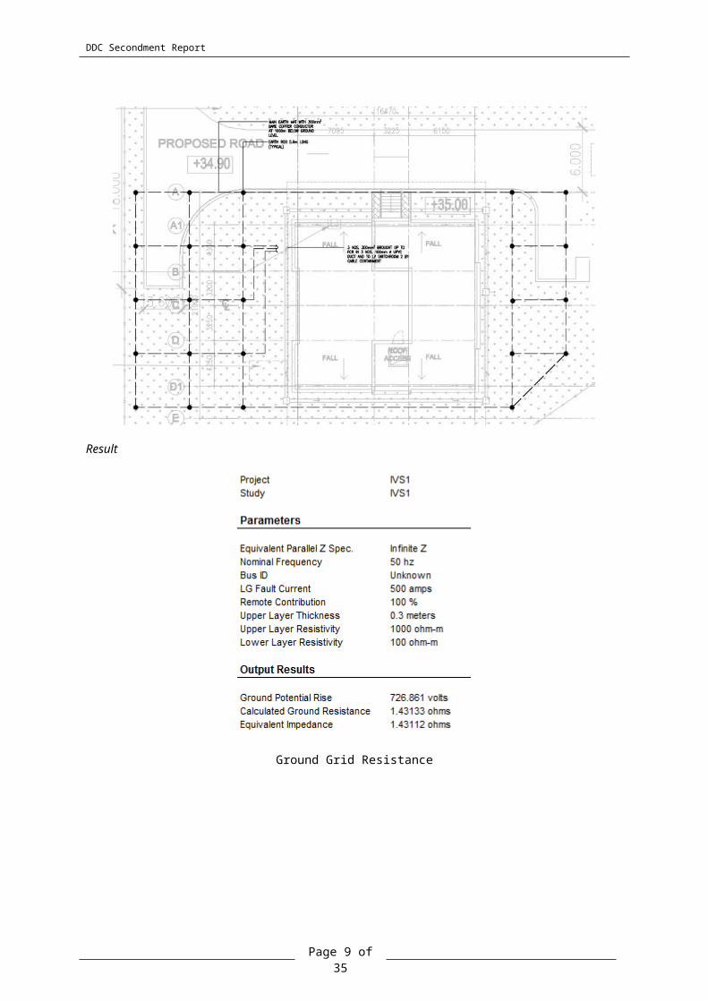
1.1 Earthing Grid Design
Earthing grid location moved from below base slab level to ground level. Detailed calculation and analysis can be referred to Appendix 1.
1.2 Drafting of Electrical and Mechanical ISD
Referring to official DDR request by MGKT and sketch by lead designer, changes were made to the electrical ISD.
2 Intervention Shaft 2
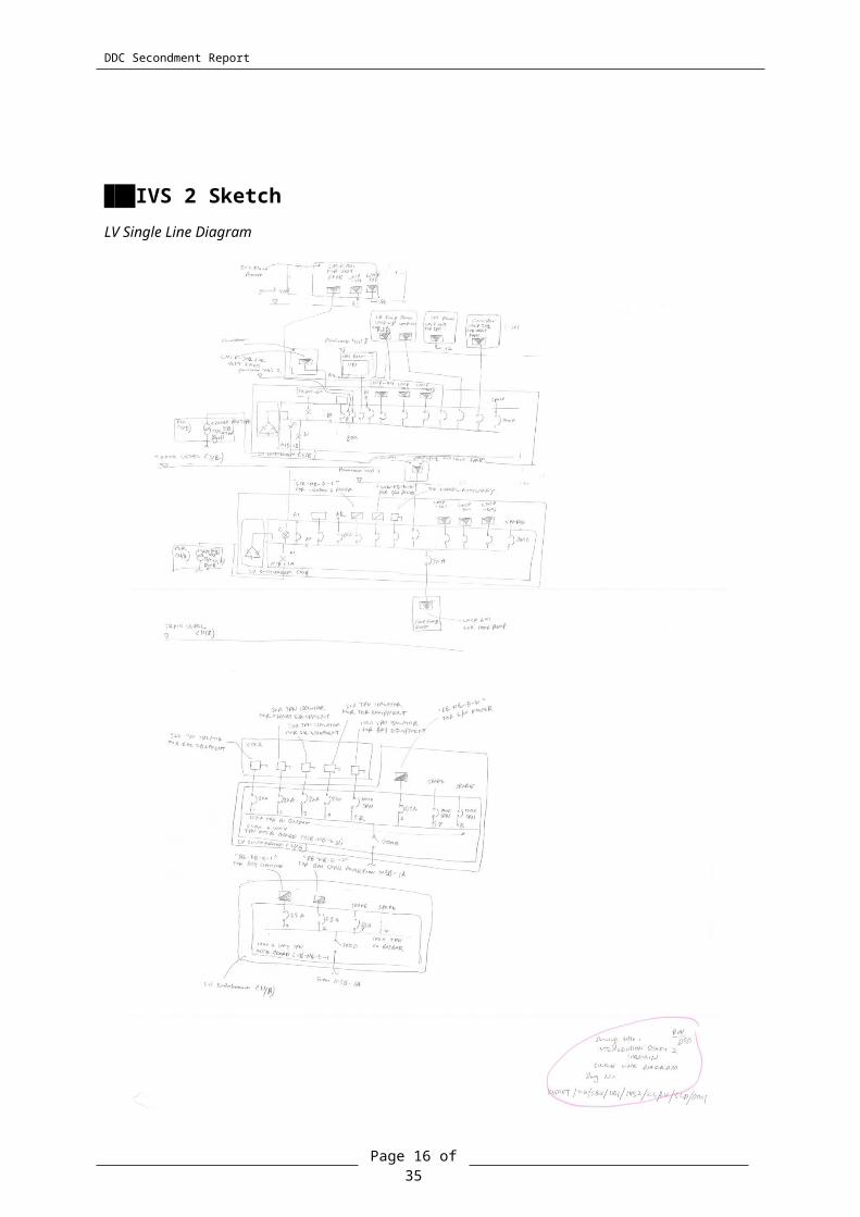
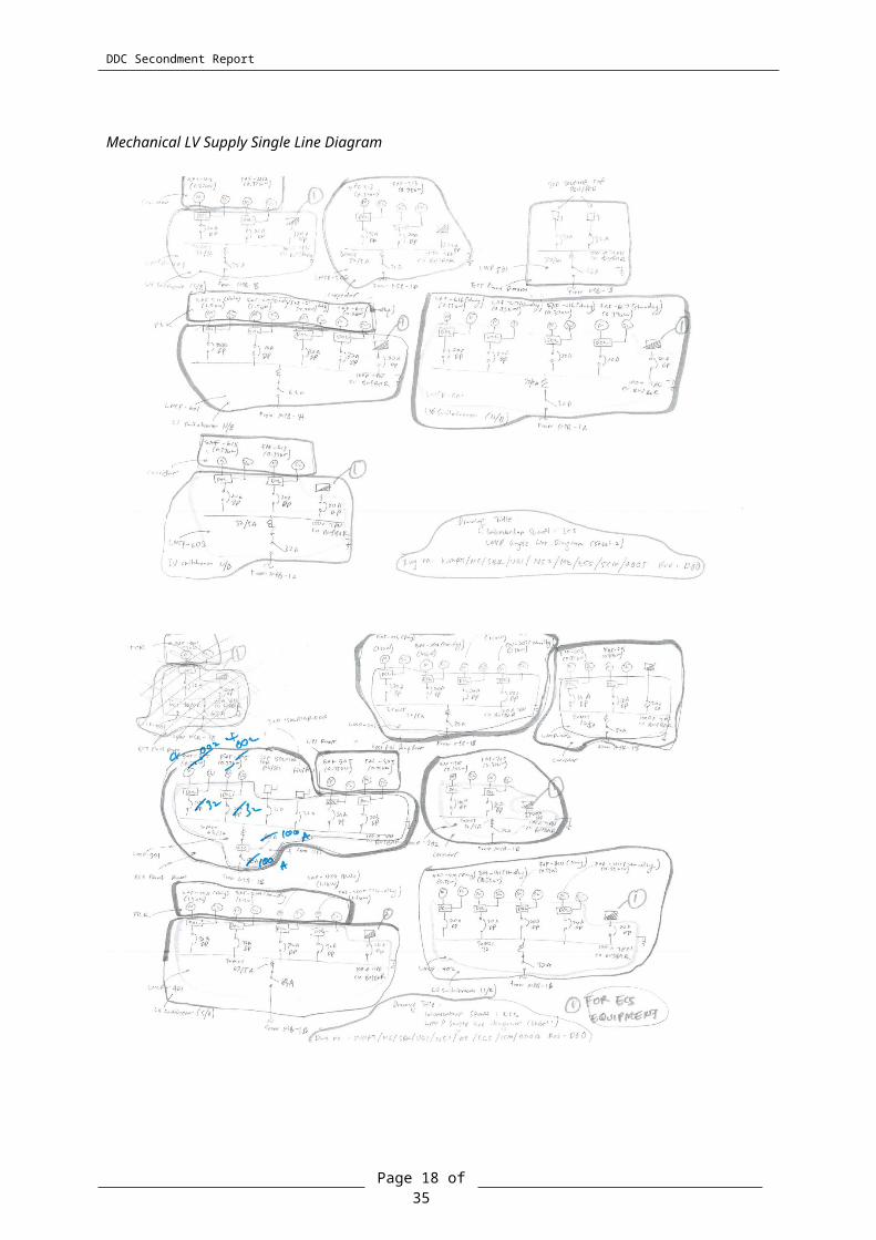
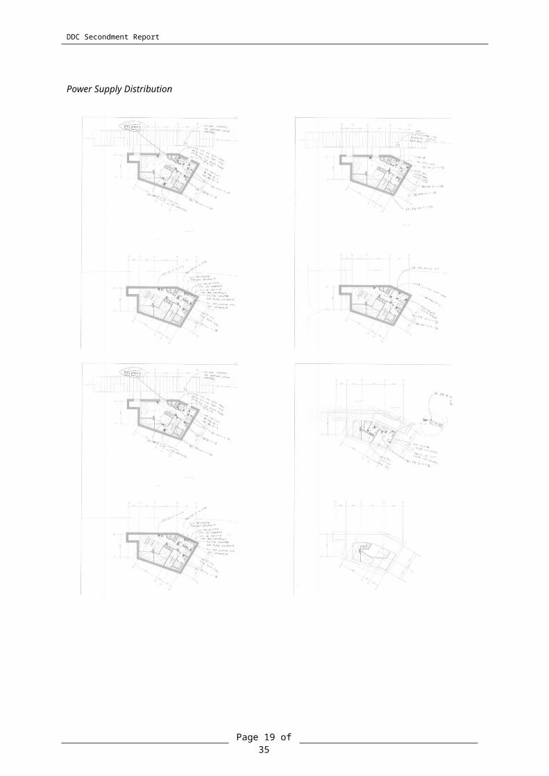
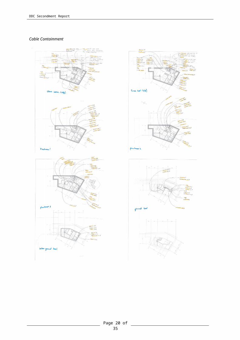
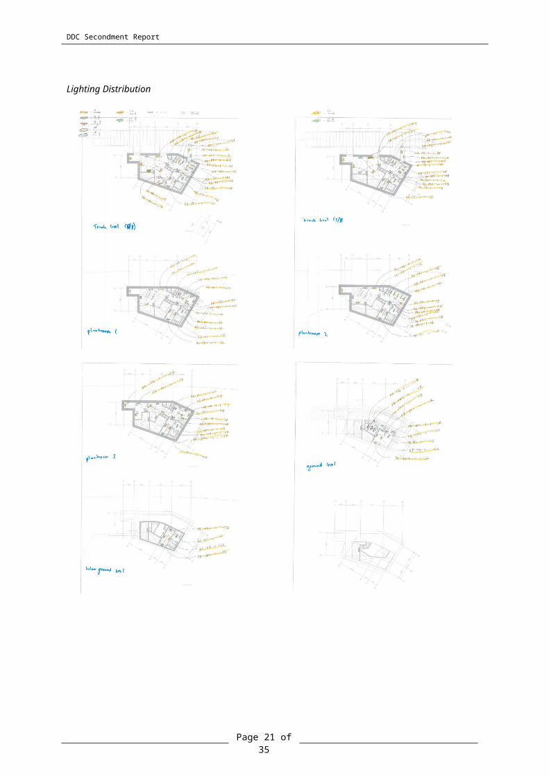
Intervention Shaft 2 (IVS2) at the time of secondment in AECOM’s office, doesn’t have prefinal design. Hence, complete electrical ISD drawings comprising electrical schematics, earthing diagram, lightning protection, cable containment, lighting and power supply distribution needs to be produced from the beginning. The sketch for the design of IVS2 can be referred to Appendix 4.
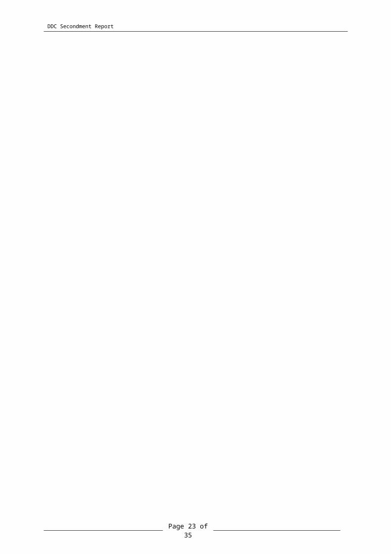
2.1 Electrical Supply Distribution and Protection
Electrical supply distribution strategy was determined by calculating the maximum demand of the building and can be referred to Appendix 2. The data is obtained from mechanical services, OWC’s power requirement and W/m2 method as per On Site Guide of BS 7671. Distribution strategy is essentially similar to Intervention Shaft 1 and as per Design Criteria 1200 (DC1200) and Design Basis Report (DBR). Care also taken to ensure loads are balanced. Sizing of protection is determined by maximum demand of the load protected.
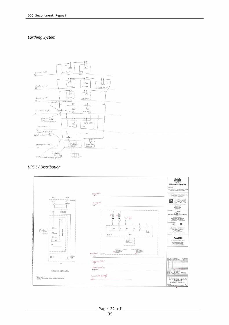
2.2 Earthing and Bonding
Since IV2’s space is limited, IVS2 earthing grid proposed to be under the base slab level. Earthing and bonding distribution follows UG1’s strategy where ring earthing system was used. The material and sizes also follows other UG1 stations and shafts design. Clean earth is located where required as per latest Interface Specifications.
Page 2 of 28
DDC Secondment Report
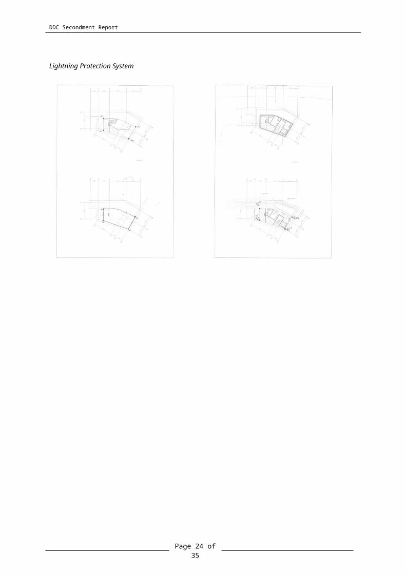
2.3 Lightning Protection
Lightning protection system for UG1 stations and shafts is designed to be indicative only. The provision of air termination, down conductor and earthing electrode are shown to indicate extend of work to be done and should be further verified by detailed calculation as required in BS EN 62305.
2.4 Cable Containment
Cable containment is designed based on number of cables to be installed and requirement in Interface Specification. 50% extra on top total of overall diameter of cable runs is used in sizing of cable tray for M&E installation. The cables in the tray are assumed to be installed in single layer flat and touching. Cable trunkings are sized according to BS 7671. The sketch can be referred to Appendix.
2.5 Lighting Design
Since IVS2 is only accessible during emergency and maintenance, detailed illumination calculation taking consideration the aesthetic value of lighting and ambiance is not warranted. To comply with illumination levels for specific rooms/areas defined in DC1200 and DBR, simple calculation of illumination is made and explained in Appendix 3.
2.6 Mechanical Service Electrical Supply Single Line Diagram
Based on location and power consumption of mechanical equipment, LMCP design is made. The LMCP design comprised of the followings:
Number of outgoing of LMCP – determined by the nearest mechanical equipment located in the LMCP location
Sizing of feeder protection CB – since induction motor in IVS2 is low powered and low duty, sizing of feeder CB is based on MCB type D. Care is taken to ensure starting current of induction motor would only cause tripping time of higher than 1 minute.
Starter type – Since the induction motors used is low duty, starter type can be determined by rule of thumb.
3 Escape Shaft 1
Escape Shaft 1 (ES1) electrical and drainage drawings were updated based on changes on architectural layout and DDR request by MGKT and MRTC. The tasks made for Escape shaft were rectifying mistakes made in previous submission and incorporating comments made by MGKT.
3.1 Electrical ISD
The electrical ISD is updated to incorporate MGKT and MRTC requests. Some of the changes made are the following:
Providing autotransformer in ES1 building to cater for excessive voltage drop and avoid the installation of large cables in the tunnel.
Replacing all RCBO for power socket circuitry to MCB only. Providing appropriate RCCB for all final DB to comply with Energy Commission requirement.
However, RCD is not provided for final circuit of inductive motor to avoid nuisance tripping.
3.2 Drainage ISD
The drainage ISD is updated to incorporate MGKT and MRTC requests. Major changes made are the following:
Page 3 of 28
DDC Secondment Report
Re-routing drainage pipe distribution to avoid drainage pipe being directly above trackway.
3.3 CSD and SEM drawings
Escape shaft 1 construction adopting top-down method, hence the CSD and SEM drawings for top level submission date is expedited. So CSD is produced by overlapping ISD drawings and rectifying any clashes and also providing clearance for man access and electromagnetic compatibility. Openings for SEM drawings are determined by quantity and sizes of M&E services penetrating through structural/architectural barrier. Adequate spare also estimated to ensure the openings are big enough to cater any minor changes of M&E services.
4 Tunnel
Design calculation is made to find optimum interval length of light fixtures in tunnel to meet requirements of NFPA 130. The calculation report can be found in Appendix 5.
5 KL Sentral Station
KL Sentral (KLS) electrical drawings are updated to suit latest architectural layout, DDR request by MGKT and MRTC and also OWC requirement. Below are the extents of changes made.
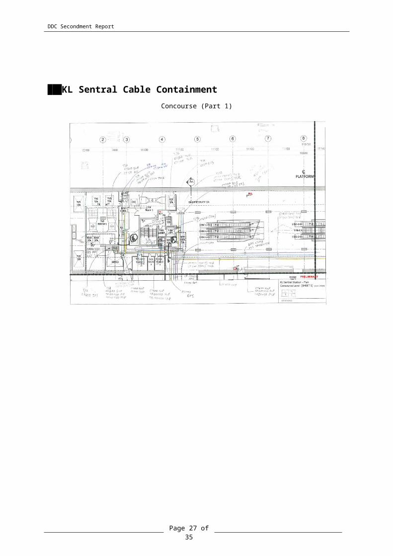
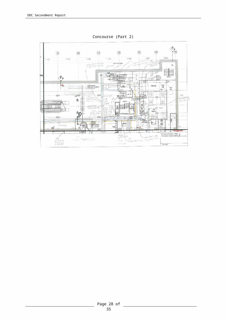
5.1 Cable Containment
Since the architectural layout of KLS is changed, the arrangement of cable containment is amended to suit the new layout. On top of that, optimization also made by determining the actual amount of cable to be installed and then determining the optimum cable containment sizes according to 50% spare rule and requirement in BS 7671. The sketch of optimized cable containment can be referred to Appendix 6.
5.2 Power Point Location
Amendment is made to power point location to suit new layout and also to comply with Interface Specifications.
5.3 ITB Schedule and Location
Referring to all ISD and typical BMS and FSCADA I/O list, ITB grouping is proposed and tabled. The location of ITB is marked in the small power layout of Electrical ISD.
5.4 Architectural Change
Improvements were made to architectural layout of KLS Station. DB Room is created in northern side of platform and the DB room in southern side was relocated. Both changes made to create a more convenient access for cable routing from concourse to platform and vice versa. The changes can be referred to Appendix 7.
Page 4 of 28
DDC Secondment Report
6 Merdeka Station
Similar like KLS, Merdeka Station (MER) is updated to suit new architectural layout and also to comply with Interface Specifications. However, the extent of work is limited to cable containment only. However, optimization could not be done because of limited timeframe to complete the task.
7 Pasar Seni Station
For Pasar Seni Station (PAS), the only task made is the update of CSD for concourse level. The update is due to changes in architectural layout. Final ISD is used to produce the CSD drawings. Clashes were identified and appropriate services’ levels are indicated in the CSD drawings.
PDP TASKS
Tasks done for PDP are limited to design verification only. The verification includes calculation of electrical system for certain elevated station to ensure proper design was made. Aside from that, proper sizing of cable containment also verified using method explained in section 2.4
1 Design Calculation of Elevated Stations
The following calculation are made for Sg Buloh Station (STN001), Kota Damansara Station (STN004) and Section 16 Station (STN012).
Voltage drop calculation Cable ampacity calculation LV Short circuit calculation and disconnection time LV L-G fault calculation and disconnection time Circuit Protective Conductor sizing Circuit breaker discrimination
The details of each calculation can be referred to Appendix 8.
2 Cable Containment Review
Using the method explained in section 2.4, cable containment sizes for STN001 and STN004 is verified.
Page 5 of 28
DDC Secondment Report
APPENDICES
1 Intervention Shaft 1 Earthing Calculation
Method
1. Calculation is made according to IEEE Standard 80:2000 – Guide for Safety in AC Substation Ground (IEEE Std 80) method and requirements and expedited by using software CYME CYMGRD.
Parameter
The following parameters are assumed
1. L-G Fault – 500 A for 3 s. Based on AECOM’s preliminary calculation using TNB requirement of 25 kA short circuit power at TNB substation, sequence network is estimated based on utilising the return protective earth conductor inside tunnel and other interconnected earthing grid. Hence, 500 A is the estimated maximum L-G Fault. 3s is assumed to be the worst disconnection time of feeder CB to IVS1.
2. Soil Resistivity – Since soil resistivity test is not yet done, assumption are made based on experience with KL Sentral Station. Hence, in line with that and level of proposed earthing grid, 2-layer soil model is used. Upper soil is assumed to be dry soil with thickness of 300mm and lower soil is assumed to be moist soil. So based on IEEE Std 80, upper layer is 1000 ohm m and lower layer is 100 ohm m.
Design
The design adopted same material and sizes used for other stations and utilising free space in the IVS1 compound. The design is as below.
Page 6 of 28
DDC Secondment Report
Result
Ground Grid Resistance
Page 7 of 28
DDC Secondment Report
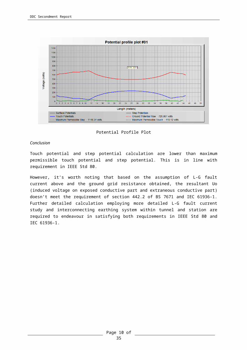
Potential Profile Plot
Conclusion
Touch potential and step potential calculation are lower than maximum permissible touch potential and step potential. This is in line with requirement in IEEE Std 80.
However, it’s worth noting that based on the assumption of L-G fault current above and the ground grid resistance obtained, the resultant Uo (induced voltage on exposed conductive part and extraneous conductive part) doesn’t meet the requirement of section 442.2 of BS 7671 and IEC 61936-1. Further detailed calculation employing more detailed L-G fault current study and interconnecting earthing system within tunnel and station are required to endeavour in satisfying both requirements in IEEE Std 80 and IEC 61936-1.
Page 8 of 28
DDC Secondment Report
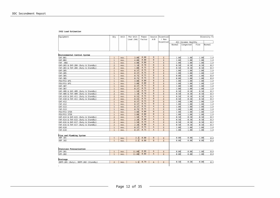
2 IVS 2 Load Estimation and Analysis IVS2 Load Estimation
Equipment Qty Unit Diversity Factor
All Incomer Healthy 1 Incomer DownNormal Congested Fire Normal Congested Fire
Environmental Control SystemEAF-001 1 nos. 3.00 0.80 B E 1.00 1.00 1.00 1.00 1.00 1.00 0.00EAF-002 1 nos. 4.00 0.80 B E 1.00 1.00 1.00 1.00 1.00 1.00 0.00FAF -002 1 nos. 4.00 0.80 A E 1.00 1.00 1.00 1.00 1.00 1.00 0.00EAF-203 & EAF-204 (Duty & Standby) 2 nos. 1.10 0.78 B E 0.50 0.50 0.50 0.50 0.50 0.50 0.00FAF-203 & FAF-204 (Duty & Standby) 2 nos. 1.00 0.75 B E 0.50 0.50 0.50 0.50 0.50 0.50 0.00EAF-205 1 nos. 0.37 0.75 B E 1.00 1.00 1.00 1.00 1.00 1.00 0.00FAF-205 1 nos. 0.37 0.75 B E 1.00 1.00 1.00 1.00 1.00 1.00 0.00EAF-305 1 nos. 0.75 0.75 B E 0.00 1.00 1.00 0.00 1.00 1.00 0.00FAF-305 1 nos. 0.75 0.75 B E 0.00 1.00 1.00 0.00 1.00 1.00 0.00PEU/PCU UPS 1 nos. 3.00 0.80 B E 1.00 1.00 1.00 1.00 1.00 1.00 0.00PEU/PCU UPS 1 nos. 3.00 0.80 B E 1.00 1.00 1.00 1.00 1.00 1.00 0.00EAF-307 1 nos. 0.37 0.75 B E 1.00 1.00 1.00 1.00 1.00 1.00 0.00FAF-307 1 nos. 0.37 0.75 B E 1.00 1.00 1.00 1.00 1.00 1.00 0.00EAF-408 & EAF-409 (Duty & Standby) 2 nos. 1.50 0.79 B E 0.50 0.50 0.50 0.50 0.50 0.50 0.00FAF-408 & FAF-409 (Duty & Standby) 2 nos. 1.10 0.78 B E 0.50 0.50 0.50 0.50 0.50 0.50 0.00EAF-410 & EAF-411 (Duty & Standby) 2 nos. 0.55 0.75 B E 0.50 0.50 0.50 0.50 0.50 0.50 0.00FAF-410 & FAF-411 (Duty & Standby) 2 nos. 0.55 0.75 B E 0.50 0.50 0.50 0.50 0.50 0.50 0.00EAF-412 1 nos. 0.37 0.75 B E 1.00 1.00 1.00 1.00 1.00 1.00 0.00FAF-412 1 nos. 0.37 0.75 B E 1.00 1.00 1.00 1.00 1.00 1.00 0.00EAF-513 1 nos. 0.37 0.75 A E 1.00 1.00 1.00 1.00 1.00 1.00 0.00FAF-513 1 nos. 0.75 0.75 A E 1.00 1.00 1.00 1.00 1.00 1.00 0.00PEU/PCU STER 1 nos. 3.00 0.80 B E 1.00 1.00 1.00 1.00 1.00 1.00 1.00PEU/PCU STER 1 nos. 3.00 0.80 B E 1.00 1.00 1.00 1.00 1.00 1.00 1.00EAF-614 & EAF-615 (Duty & Standby) 2 nos. 1.50 0.79 A E 0.50 0.50 0.50 0.50 0.50 0.50 0.00FAF-614 & FAF-615 (Duty & Standby) 2 nos. 2.20 0.80 A E 0.50 0.50 0.50 0.50 0.50 0.50 0.00EAF-616 & EAF-617 (Duty & Standby) 2 nos. 1.50 0.79 A E 0.50 0.50 0.50 0.50 0.50 0.50 0.00FAF-616 & FAF-617 (Duty & Standby) 2 nos. 2.20 0.80 A E 0.50 0.50 0.50 0.50 0.50 0.50 0.00EAF-618 1 nos. 0.37 0.75 A E 1.00 1.00 1.00 1.00 1.00 1.00 0.00FAF-618 1 nos. 0.37 0.75 A E 1.00 1.00 1.00 1.00 1.00 1.00 0.00
Fire and Plumbing SystemHRP 101 1 nos. 2.2 0.80 B E 0.00 0.00 1.00 0.00 0.00 1.00 0.00HRP 102 1 nos. 2.2 0.80 B E 0.00 0.00 0.00 0.00 0.00 0.00 0.00
Staircase PressurisationSPF-201 1 nos. 11.00 0.88 A E 0.00 0.00 1.00 0.00 0.00 1.00 0.00SPF-202 1 nos. 11.00 0.88 A E 0.00 0.00 1.00 0.00 0.00 1.00 0.00
DrainageDRPP-201 (Duty), DRPP-202 (Standby) 2 nos. 1.5 0.79 A E 0.50 0.50 0.00 0.50 0.50 0.00 0.00
Per Unit Load (kW)
Power Factor
Source A/B
Essential/ Non
EssentialLoss of Both
Incomers
Page 9 of 28
DDC Secondment Report
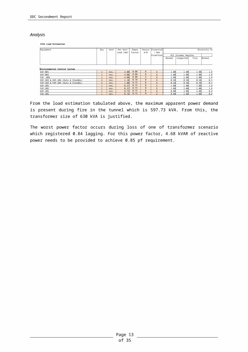
Analysis
IVS2 Load Estimation
Equipment Qty Unit Diversity Factor
All Incomer Healthy 1 Incomer DownNormal Congested Fire Normal Congested Fire
Environmental Control SystemEAF-001 1 nos. 3.00 0.80 B E 1.00 1.00 1.00 1.00 1.00 1.00 0.00EAF-002 1 nos. 4.00 0.80 B E 1.00 1.00 1.00 1.00 1.00 1.00 0.00FAF -002 1 nos. 4.00 0.80 A E 1.00 1.00 1.00 1.00 1.00 1.00 0.00EAF-203 & EAF-204 (Duty & Standby) 2 nos. 1.10 0.78 B E 0.50 0.50 0.50 0.50 0.50 0.50 0.00FAF-203 & FAF-204 (Duty & Standby) 2 nos. 1.00 0.75 B E 0.50 0.50 0.50 0.50 0.50 0.50 0.00EAF-205 1 nos. 0.37 0.75 B E 1.00 1.00 1.00 1.00 1.00 1.00 0.00FAF-205 1 nos. 0.37 0.75 B E 1.00 1.00 1.00 1.00 1.00 1.00 0.00EAF-305 1 nos. 0.75 0.75 B E 0.00 1.00 1.00 0.00 1.00 1.00 0.00FAF-305 1 nos. 0.75 0.75 B E 0.00 1.00 1.00 0.00 1.00 1.00 0.00
Per Unit Load (kW)
Power Factor
Source A/B
Essential/ Non
EssentialLoss of Both
Incomers
From the load estimation tabulated above, the maximum apparent power demand is present during fire in the tunnel which is 597.73 kVA. From this, the transformer size of 630 kVA is justified.
The worst power factor occurs during loss of one of transformer scenario which registered 0.84 lagging. For this power factor, 4.68 kVAR of reactive power needs to be provided to achieve 0.85 pf requirement.
Page 10 of 28
DDC Secondment Report
3 IVS 2 Back of House Lighting Calculation
Method
1. The calculation is made using Lumen Output Method to satisfy the requirement in DC1200. To expedite the calculation, Microsoft Excel was used.
Parameter
The following parameters is used
1. Lumen output per fitting – 2600 lm. Based on manufacturer’s data of 1x28W T5 Batten.
2. Maintenance Factor and Safety Factor – 0.5.
3. Coefficient of reflectance – 0.5/0.3/0.2 (ceiling/floor/wall).
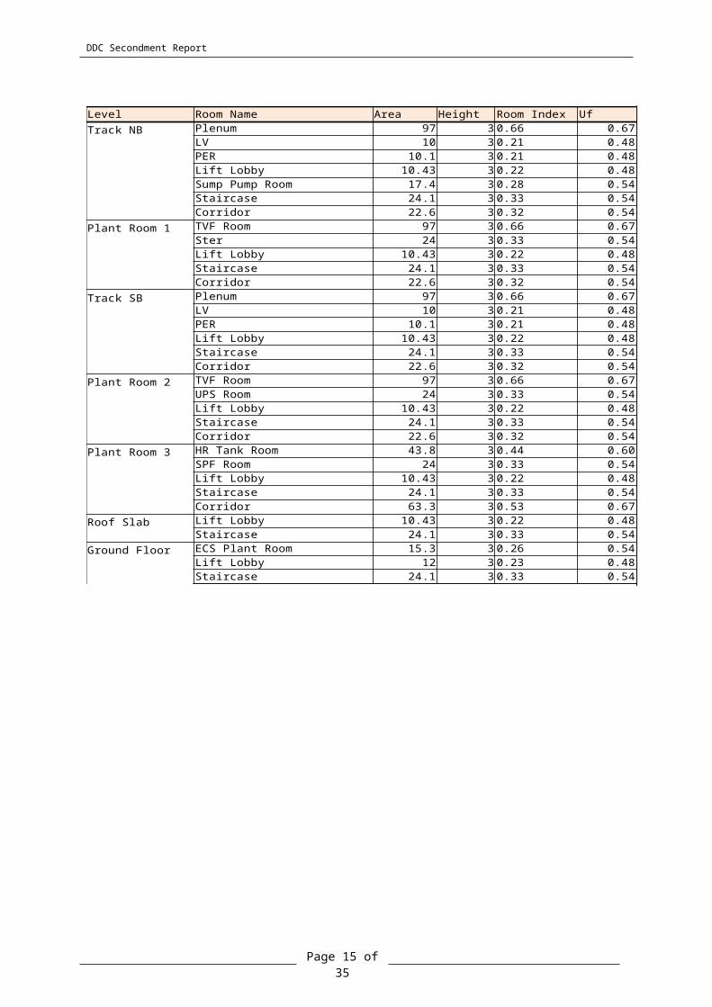
Calculation Result
Level Room Name Area Height Room Index Uf Lux Req QtyTrack NB Plenum 97 3 0.66 0.67 100 12
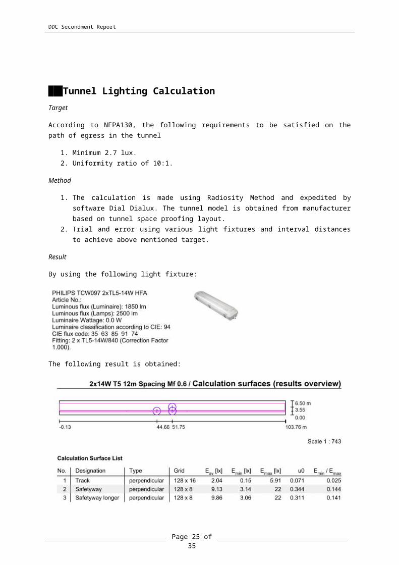
According to NFPA130, the following requirements to be satisfied on the path of egress in the tunnel
1. Minimum 2.7 lux.2. Uniformity ratio of 10:1.
Method
1. The calculation is made using Radiosity Method and expedited by software Dial Dialux. The tunnel model is obtained from manufacturer based on tunnel space proofing layout.
2. Trial and error using various light fixtures and interval distances to achieve above mentioned target.
Result
By using the following light fixture:
The following result is obtained:
Conclusion
At 12m interval, 2x14W T5 light fixture can achieve the targets.
Page 20 of 28
DDC Secondment Report
6 KL Sentral Cable Containment
Concourse (Part 1)
Page 21 of 28
DDC Secondment Report
Concourse (Part 2)
Page 22 of 28
DDC Secondment Report
Concourse (Part 3)
Concourse (Part 4)
Page 23 of 28
DDC Secondment Report
Platform (Part 1)
Platform (Part 2)
Page 24 of 28
DDC Secondment Report
Platform (Overall)
Page 25 of 28
DDC Secondment Report
7 KLS Architectural Layout
Platform
Concourse
Page 26 of 28
DDC Secondment Report
Page 27 of 28
DDC Secondment Report
8 Electrical Design Calculation of Elevated Station
For Sg Buloh Station (STN001), Kota Damansara Station (STN004) and Section 16 Station (STN012), calculation mentioned in Section is made. The following outline the extent of calculation made for every calculation type:
LV Distribution Modelling
The LV distribution of the system is modelled in the software Bentley Hevacomp for ease of calculation. Below is the model of STN001 for reference.
Cable Size Verification
To do a calculation on cable sizing, the following calculation is made:
Cable ampacity is calculated based on maximum current demand. Corresponding cable sizes and types are referred to Appendix in BS 7671.
The voltage drop at final DB must not exceed 2.5%. The voltage drop per meter per ampere is obtained from Appendix in BS 7671 for corresponding cable sizes and types.
Short Circuit Calculation
Short circuit calculation is based on infinite bus method and done on every panel’s installation.
Earth Fault Calculation
Earth fault calculation is based on infinite bus method and done on every panel’s installation.
Circuit Breaker Selection and Coordination
Once short circuit and earth fault calculation is made, selection of circuit breaker is justified by checking the disconnection time and also the discrimination of circuit breaker tripping at every point of fault. The disconnection time was ensured to below as 5s as per BS 7671 requirement for TN-S system. The selectivity is based on time-current selectivity and the data is obtained from manufacturer.
The above calculations are repeated for every electrical scenario which includes:
Normal operation Loss of single supply (load shedding mode) Loss of both supply (genset mode)