Page 1
8/6/2019 Aerial Wind Turbine MQP09
http://slidepdf.com/reader/full/aerial-wind-turbine-mqp09 1/61
Aerial Wind Turbine
A Major Qualifying Project Report
Submitted to the faculty
Of
Worcester Polytechnic Institute
In partial fulfillment of the requirements for the
Degree of Bachelor of Science
Submitted By:
Kevin Martinez
Andrew McIsaac
Devin Thayer
Advisor: Professor Gretar Tryggvason
Date: April 30, 2009
Page 2
8/6/2019 Aerial Wind Turbine MQP09
http://slidepdf.com/reader/full/aerial-wind-turbine-mqp09 2/61
2
Abstract:
Land based wind turbines are not used to their fullest potential due to the inconsistency
of wind near the earth’s surface. The goal was to determine if a structure could be designed
and built to harness wind energy at high altitudes. Using a non-rigid airship, a design was
created to lift wind turbines up to a desired height while still achieving a moderate power
output.
Page 3
8/6/2019 Aerial Wind Turbine MQP09
http://slidepdf.com/reader/full/aerial-wind-turbine-mqp09 3/61
3
Executive Summary:
The rising cost of oil is increasing the need to find alternative energy sources. One
source is harnessing the power of wind which is less harmful to the environment. Commonly,
wind turbines are fixed to the ground and can only reach heights of up to 125 meters. There are
also issues with the consistency of the wind speeds and direction at these heights. Wind
turbines installed at these heights do not produce as much power as they could due to the
inconsistency of the winds.
The goal of this project was to determine a way to elevate the turbines up to
heights of 300 meters using a lighter than air structure. At this altitude, the wind speeds are
more constant and the direction of the wind does not vary. With these two factors significantly
improved, the turbines operate at their maximum potential.
Many steps were involved to reach these goals. To start off, a preliminary design
of the structure including the support beams, tether and turbines was created. The summation
of the forces from weight and drag associated with the structure were found. These numbers
were needed to determine the volume of hydrogen required to overcome the total weight.
With the drag forces calculated, the strength of the tether combined with the angle formed
between the tether and ground were determined. The turbines are aligned facing backwards so
they do not interfere with the tethering system. Wings were added to provide additional lift to
reduce the amount of hydrogen needed.
Page 4
8/6/2019 Aerial Wind Turbine MQP09
http://slidepdf.com/reader/full/aerial-wind-turbine-mqp09 4/61
4
The future of aerial wind turbines is promising with the expectation that
technology will reduce the weight and size of wind turbines while maintaining the same power
capacity. The final design is a feasible solution to the goal of the project but would be better if
the overall size of the structure could be smaller in the future.
Figure 1: Isometric view of structure
Page 5
8/6/2019 Aerial Wind Turbine MQP09
http://slidepdf.com/reader/full/aerial-wind-turbine-mqp09 5/61
5
Contents
Abstract: .......................................................................................................................................... 2
Executive Summary: ........................................................................................................................ 3
Table of Figures ............................................................................................................................... 7
1.0 Introduction: ............................................................................................................................. 8
2.0 Background: ............................................................................................................................ 10
2.1 Wind Power: ........................................................................................................................... 10
2.2 Wind Turbines: ........................................................................................................................ 12
2.3 Patent Search: ......................................................................................................................... 16
2.4 Airships: ................................................................................................................................... 20
3.0 Design Prototype: ................................................................................................................... 23
3.1 Preliminary Volume Calculations: .......................................................................................... 25
3.2 Surface Area: .......................................................................................................................... 26
3.3 Hanging Supports: .................................................................................................................. 27
3.4 Power Lines: ........................................................................................................................... 28
3.5 Drag Force: ............................................................................................................................. 30
3.6 Area of Tether: ....................................................................................................................... 31
3.7 Wing: ...................................................................................................................................... 32
3.8 Horizontal Beam:.................................................................................................................... 35
3.9 Support Cables/Rods: ............................................................................................................. 38
3.10 Maximum Fatigue Load on Supports: .................................................................................. 40
3.11 Calculating Mass: ................................................................................................................. 42
3.12 Solving for Volume: ............................................................................................................... 43
4.0 Conclusions/Future Work: ...................................................................................................... 45
Page 6
8/6/2019 Aerial Wind Turbine MQP09
http://slidepdf.com/reader/full/aerial-wind-turbine-mqp09 6/61
6
Works Cited ................................................................................................................................... 49
Appendix A: ................................................................................................................................... 50
Page 7
8/6/2019 Aerial Wind Turbine MQP09
http://slidepdf.com/reader/full/aerial-wind-turbine-mqp09 7/61
7
Table of FiguresFigure 1: Isometric view of structure .................................................................................. 4
Figure 2: Size specification of common industrial wind turbines ..................................... 15
Figure 3: ZEPPELIN NT ....................................................................................................... 21
Figure 4: Envelope............................................................................................................. 26
Figure 5: Horizontal Beam ................................................................................................ 36
Figure 6: Cross section of hanging support ...................................................................... 40
Page 8
8/6/2019 Aerial Wind Turbine MQP09
http://slidepdf.com/reader/full/aerial-wind-turbine-mqp09 8/61
8
1.0 Introduction:
With the shortage of fossil fuels, alternative energy has been thrust into the national
spotlight as a major necessity in order to keep up with the increasing energy demands of the
world. One of these alternative energies is wind power. Although there has been an increasing
interest in using turbines to harness the power of the wind, only a small percentage of those
have focused on higher altitudes where the wind is more constant. The development and
growth of land-based wind turbines has increased exponentially over the years as countries and
businesses alike seek renewable energy sources. Whether the reason is funding or technical
challenges, few companies are attempting to take on the winds at altitudes higher than 125 m
[1].
Most designs for wind power have utilized a turbine anchored to the ground via a huge
tower. Problems with these designs are that the intermittency of the wind causes most of these
devices to be idle a majority of the time, with only 30 percent efficiency at most [2]. Cost is
another major issue where a turbine with a 91 meter diameter that produces 2.5 megawatts
costs about $14 million to design and build [2].
Reducing carbon dioxide emissions is a major contributing factor in alternative energy
proposals. From the US average fuel mix, about 1.5 pounds of CO2 are emitted for every
kilowatt hour that is generated. Electricity consumption accounted for more than 2.3 billion
tons of CO2 in 2006. This accounted for 39.5 percent of the total emissions from human
resources, according to the US Department of Energy [3]. Coal-fired plants alone released over
Page 9
8/6/2019 Aerial Wind Turbine MQP09
http://slidepdf.com/reader/full/aerial-wind-turbine-mqp09 9/61
9
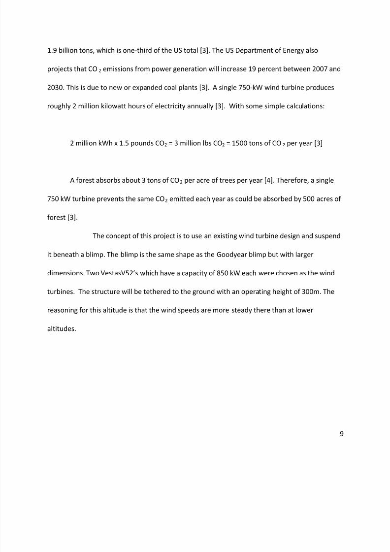
1.9 billion tons, which is one-third of the US total [3]. The US Department of Energy also
projects that CO 2 emissions from power generation will increase 19 percent between 2007 and
2030. This is due to new or expanded coal plants [3]. A single 750-kW wind turbine produces
roughly 2 million kilowatt hours of electricity annually [3]. With some simple calculations:
2 million kWh x 1.5 pounds CO2 = 3 million lbs CO2 = 1500 tons of CO 2 per year [3]
A forest absorbs about 3 tons of CO2 per acre of trees per year [4]. Therefore, a single
750 kW turbine prevents the same CO2 emitted each year as could be absorbed by 500 acres of
forest [3].
The concept of this project is to use an existing wind turbine design and suspend
it beneath a blimp. The blimp is the same shape as the Goodyear blimp but with larger
dimensions. Two VestasV52’s which have a capacity of 850 kW each were chosen as the wind
turbines. The structure will be tethered to the ground with an operating height of 300m. The
reasoning for this altitude is that the wind speeds are more steady there than at lower
altitudes.
Page 10
8/6/2019 Aerial Wind Turbine MQP09
http://slidepdf.com/reader/full/aerial-wind-turbine-mqp09 10/61
10
2.0 Background:
2.1 Wind Power:
Wind power first began around 5000 B.C. [5] with the use of sailboats. The sailors
understood the use of aerodynamic lift, just not why it happened or how. But their experience
and knowledge aided in the first versions of known windmills in Persia around 500-900 A.D. [5].
They were used for pumping water and grinding grain. The design evolved and was later used in
Europe for similar purposes. Up until 1870 the blades were made out of wood [5]. The
addition of steel blades to the design enabled them to be lighter and have more efficient
shapes. These resulted in much higher speeds and a need to gear the windmills down to match
the speed of the pump. In 1888, the first electricity generating windmill was built [5]. It
produced 12 kilowatts with a 17 meter rotor [5]. Improvements to the design allowed for the
production of up to 25 kW per windmill [5]. Jumping ahead, the United States government
took an interest in wind energy after the “Arab oil crisis” of 1973 *5]. While this was not a large
success, it does represent the beginning of the United States government realizing the
weaknesses of oil based energy and looking towards more renewable energy sources. For the
next twenty years much developmental research and testing was completed to solve many of
the issues with windmill designs [5]. Current designs are far more efficient and able to produce
energy in the magnitude of megawatts rather than kilowatts. However, as with most things,
more can be done to increase the efficiency and power output of this renewable resource.
Page 11
8/6/2019 Aerial Wind Turbine MQP09
http://slidepdf.com/reader/full/aerial-wind-turbine-mqp09 11/61
11
The modern design consists of a 1-3 Megawatt turbine [2] with 2 or more blades that
have a rotor diameter between 70 and 100 meters [2]. Most turbine designs have three blades
but it is said that the 2 blade design will become the norm for offshore wind farms [2]. The
blades are shaped much like an airplane’s wings in order to create lift from air moving over the
blade [2]. Generally blades are made of a composite material structure. The best type is the
wood laminates which prove to be the strongest and lightest.
Most modern wind turbine towers are conical tubular steel towers. They can range in
height from 30 to 85 meters depending on the tower costs per meter, how much the wind
locally varies with height above ground level, and the price the turbine owner gets for an
additional kilowatt hour of electricity [5]. They are manufactured in sections of 20-30 meters
[5] and are bolted together on site. The conical design is used to increase their strength while
also saving materials at the same time.
When it comes to extracting power from the wind, there are some problems with
finding a consistent wind. This greatly affects how efficient a wind turbine can be. From Betz’s
linear momentum theory, the maximum energy that can be extracted is 60 percent while most
designs nowadays get around 30-40 percent [2]. A speed of 12 m/s is needed to get this
maximum efficiency [2]. Any speeds higher than this will decrease efficiency and could
potentially damage the turbine. Another way of increasing the efficiency of the turbine is to
allow the rotor to change its rate of rotation as the wind speed changes. This is known as
variable speed operation where the generators allow for variable rates of rotation while still
Page 12
8/6/2019 Aerial Wind Turbine MQP09
http://slidepdf.com/reader/full/aerial-wind-turbine-mqp09 12/61
12
producing alternating current electricity [2]. However, most designs are still of the fixed speed
operation where all the components are much cheaper with a loss of 20 percent energy
production [2].
There are numerous factors which affect the size and design of a wind turbine.
Almost all the factors can be placed in two groups: time-dependent and frequency-dependent
[2]. Forces from the wind, the unwanted vibrations of rotational frequency, and the fatigue
effects of the constant rise and fall of the blades all influence the design process [2]. With
power output goals in mind, the power capture is proportional to the swept rotor area. This
will only increase to a certain range where the component size and machine cost outweighs the
effectiveness. Conversely this “range” has greatly increased over the years as manufacturing
and operational understanding is gained.
2.2 Wind Turbines:
The market for wind energy is expanding every day and many different companies are
becoming involved or have been since the start. Companies all over the world are supplying
wind energy to the residential market as well as building wind farms with hundreds of wind
turbines for commercial use. A single wind turbine can output as little as 100 kW of power all
the way up to 6 MW of power [3]. The amount of power produced is relative to the size and
location of the turbines. The use of wind energy is increasing and potentially could power many
areas of the world in the years to come.
Page 13
8/6/2019 Aerial Wind Turbine MQP09
http://slidepdf.com/reader/full/aerial-wind-turbine-mqp09 13/61
13
There are several big names in the turbine business: Vestas (Denmark), GE (US), Gamesa
(Spain), Enercon (Germany), Suzlon (India), Siemens (Germany), REpower (Germany). Each of
these companies has developed a wide range of turbines for varying power levels and different
locations with assorted wind conditions.
Vestas, a German company has wind turbines all across the world. They design 4 types
of turbines that output power at a range from 850 kW to 3 MW. Their largest, 3 MW, turbine
has a diameter of 90m with a weight of 41 tons which includes only the hub and rotor. Vestas
has wind turbines in Europe, Denmark, the USA and China [6].
GE has been developing turbines for years now and has several models. Currently, GE
has a 1.5 MW, 2.5 MW and a 3.6 MW turbine available to the market. The most advanced one
is their 3.6 MW version that they have available for offshore installations. It has a rotor
diameter of 111m and is rated at wind speeds of 14 m/s [7].
Gamesa is based in Spain and has turbines ranging from 850 kW to 2 MW. They have
turbines designed for different wind speeds such as low, medium and high. The weights of their
turbines rotor and blade combinations range from 10 tons up to 36 tons each [8].
Enercon, out of Germany, has the largest turbines on the market today. Their turbines
are able to create power of over 6 MW each. These structures have a rotor diameter of 126
meters and are rated at 6 MW but have the potential to reach upwards of 7 MW. Enercon also
Page 14
8/6/2019 Aerial Wind Turbine MQP09
http://slidepdf.com/reader/full/aerial-wind-turbine-mqp09 14/61
14
has smaller scaled turbines ranging from 330 kW to 2 MW. They have close to 7,000 wind
turbines in Germany and around 15,000 installed around the globe [9].
Suzlon, Siemens and REpower are all competing companies as well, with turbines
starting at less than 1 MW. REpower was the leader for a while with their 5 MW turbine [10,
11, 12].
One must investigate the entire industry to get a grasp on what is going on in the world
relating to wind turbine technology. There are wind turbines all over the world and some places
are more advanced than others. According to the World Wind Energy Association [13], in 2008
the top five countries in terms of installed capacity are the US (25.17 GW), Germany (23.9 GW),
Spain (16.74 GW), China (12.2 GW) and India (9.587 GW).
Wind energy is on the rise and should only increase with time. This environmentally
friendly way to create electricity can power approximately 650 European households per every
1 MW turbine. Most turbines today are built to produce at least 2 MW [14].
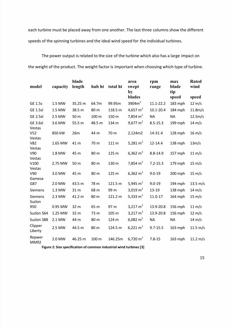
Figure 1 compares some of the major wind turbine companies. The capacity is how
much energy a single turbine can create. It ranges from 850 kW to 3.6 MW. The blade length is
the span of a single blade and the hub height is the height of the tower which it is supported by.
The total height is the distance from the ground to the tip of a vertical blade. The swept area is
found by using the blade length as the radius and finding its circular area. This area is
important for determining the total power output of the turbine. The area also affects how far
Page 15
8/6/2019 Aerial Wind Turbine MQP09
http://slidepdf.com/reader/full/aerial-wind-turbine-mqp09 15/61
15
each turbine must be placed away from one another. The last three columns show the different
speeds of the spinning turbines and the ideal wind speed for the individual turbines.
The power output is related to the size of the turbine which also has a large impact on
the weight of the product. The weight factor is important when choosing which type of turbine.
model capacity blade
length hub ht total ht
area
swept
rpm
range
max
blade
Rated
wind
by
blades
tip
speed speed
GE 1.5s 1.5 MW 35.25 m 64.7m 99.95m 3904m2 11.1-22.2 183 mph 12 m/s
GE 1.5sl 1.5 MW 38.5 m 80 m 118.5 m 4,657 m2 10.1-20.4 184 mph 11.8m/s
GE 2.5xl 2.5 MW 50 m 100 m 150 m 7,854 m2 NA NA 12.5m/s
GE 3.6sl 3.6 MW 55.5 m 48.5 m 134 m 9,677 m2 8.5-15.3 199 mph 14 m/s Vestas
V52 850 kW 26m 44 m 70 m 2,124m2 14-31.4 128 mph 16 m/s Vestas
V82 1.65 MW 41 m 70 m 111 m 5,281 m2 12-14.4 138 mph 13m/s Vestas
V90 1.8 MW 45 m 80 m 125 m 6,362 m2 8.8-14.9 157 mph 11 m/s Vestas
V100 2.75 MW 50 m 80 m 130 m 7,854 m2 7.2-15.3 179 mph 15 m/s Vestas
V90 3.0 MW 45 m 80 m 125 m 6,362 m2 9.0-19 200 mph 15 m/s Gamesa
G87 2.0 MW 43.5 m 78 m 121.5 m 5,945 m2 9.0-19 194 mph 13.5 m/s
Siemens 1.3 MW 31 m 68 m 99 m 3,019 m2 13-19 138 mph 14 m/s
Siemens 2.3 MW 41.2 m 80 m 121.2 m 5,333 m2 11.0-17 164 mph 15 m/s Suzlon
950 0.95 MW 32 m 65 m 97 m 3,217 m2 13.9-20.8 156 mph 11 m/s
Suzlon S64 1.25 MW 32 m 73 m 105 m 3,217 m2 13.9-20.8 156 mph 12 m/s
Suzlon S88 2.1 MW 44 m 80 m 124 m 6,082 m2 NA NA 14 m/s
Clipper
Liberty 2.5 MW 44.5 m 80 m 124.5 m 6,221 m2 9.7-15.5 163 mph 11.5 m/s
Repwer
MM92 2.0 MW 46.25 m 100 m 146.25m 6,720 m2 7.8-15 163 mph 11.2 m/s
Figure 2: Size specification of common industrial wind turbines [3]
Page 16
8/6/2019 Aerial Wind Turbine MQP09
http://slidepdf.com/reader/full/aerial-wind-turbine-mqp09 16/61
16
2.3 Patent Search:
The present state of aerial wind turbine design is one in which designers have thought
of many designs ranging from the simplest form of a kite/airfoil attached to a rope to the most
radical proposals. However, there is a general picture that can be formed that encompasses
most of the designs. Most of the designs have some sort of tethering system that anchors the
structure to the ground or a platform in the water. All of them also have either a blimp or type
of airfoil that keeps the whole system in the air. There next is a component that is used to
harness the wind and convert it to electrical energy whether it is a turbine or a pulley design
that turns a separate generator.
Although these ideas seem to be recent as of the last decade, patents were granted to
engineers in the 70’s for several aerial wind turbine designs. However, these designs consisted
more of general ideas with multiple interpretations of the actual final product. Most of the
patents found on this subject from the 70’s and 80’s had to do with the concepts of harnessing
the wind and not all the logistics involving a final product.
US patent number 4,073,516 was one such example in which there are a lot of general
ideas and little specifics. “Wind-Driven Power Plant” was issued a patent in June of 1975. Its
design called for a power plant having a rotor assembly with at least one rotor connected to a
generator. A gas-filled hollow body keeps the whole system in the air. The designer called for
the whole system to be either anchored to the ground or be suspended in the air with a floating
body. It would have some sort of means for aligning the rotors with the wind direction. There is
Page 17
8/6/2019 Aerial Wind Turbine MQP09
http://slidepdf.com/reader/full/aerial-wind-turbine-mqp09 17/61
17
also a possibility for the use of one cable to act as both the tethering system and the power
transmitting wire. The designer suggests that the generated power be used while in the air
through powering a transmitter or for energizing optical display devices. There is also at least
one pair of coaxially supported counter rotating rotors that compensate for the spinning of the
turbine. This causes rotors to always become aligned into the prevailing winds. Another key
aspect of the design is a suspension body that is connected to a brace by a joint having three
degrees of freedom (i.e. gimbal joint connection). This type of connector allows the suspended
turbine to be readily changed to any pitch or attitude necessary for facing the wind. The balloon
can be connected to the turbine via a net-like wrapping applied over the balloon. At the bottom
there would be a connecting joint to which the rotor assembly attaches much like a gas balloon
[15].
A much different design from the earlier decades would be US patent 4,491,739 entitled
“Airship-Floated Wind Turbine.” The goal for this patent was to create a wind turbine with a
diameter reaching 1,000 feet with operational heights of several thousand feet. In this design,
the airship holds up a large ring which supports the outer ends of the turbine blades that
extend inward from the ring to the airship. A bearing assembly was created that allows the
airship to rotate without twisting the tether line. The ring around the airship is basically a large
“space frame” structure that holds all the turbine blades on the outer edges . This greatly
reduces the weight of the whole structure [15].
Page 18
8/6/2019 Aerial Wind Turbine MQP09
http://slidepdf.com/reader/full/aerial-wind-turbine-mqp09 18/61
18
A more conventional design is US patent 4,450,364 with the title of “Lighter than Air
Wind Energy Conversion System Utilizing a Rotating Envelope.” This is a system where the main
rotors spin independently of the gas-filled structures. It is self-orienting and includes
aerodynamic damping of orientation motions. However, it still requires large heavy rotor
blades. The rotor blades are designed to be rotated by the wind in a plane perpendicular to the
longitudinal axis of the structure. There is also a non-rotating tail for orienting the structure
while also providing some additional lift. Generators are positioned on the rotor blades in order
to generate the electricity. The complete system is tethered to the ground by at least one
tethering cable and one electrical cable. The designer also suggests that there be some type of
mooring system on the cable with the ability to draw the cable in and tether it closer to the
ground [15].
Many of the newer designs and patents have incorporated key aspects of earlier designs
while taking them a step further by going into great detail about the tethering system or the
actual design for the turbine. They are generally much more complete than the earlier patents.
One such design is patent 6,523,781 titled “Axial Load Linear Wind-Turbine.” This design
can be used at any height from 300 feet to 3,000 feet. It is meant to capture the wind in the
axial direction, perpendicular to the airfoil’s flight direction. Most of the expensive and heavy
components are on the ground and only the airfoils are in the air. The system consists of three
airfoil kites in tandem connected to a ground anchor. The kite operates at high speeds with the
airfoil moving mostly perpendicular to the wind stream. Adjusting the length of the control
lines in turn controls the airfoils direction and speed. The three airfoils are angled into the rising
Page 19
8/6/2019 Aerial Wind Turbine MQP09
http://slidepdf.com/reader/full/aerial-wind-turbine-mqp09 19/61
19
wind which causes the pulley and shaft to turn a generator on the ground. Since the generator
is on the ground, there is no need for an electrical cable running to the apparatus that is in air.
This greatly reduces one of the major problems in terms of receiving the energy from the
turbines in the air. Once the airfoils reach the maximum height, their pitch becomes negative
and they fall back to the starting position to start the cycle again [15].
Another present-day design for a wind turbine is US patent 7,129,596 entitled “Hovering
Wind Turbine.” This a fairly simple design in which the turbine is one that would be seen on a
residential unit. The blades lie on the surface of an imaginary horizontal cylinder with their
pitch angle changing as a result of the rotational angle. This allows the turbine to gather wind
energy mainly in the upwind and downwind areas of the cylindrical path. It also uses a fraction
of the gathered energy to create lift by deflecting air downwards, mostly in the upper and
lower areas of the cylindrical path. The remainder of the wind energy is used to drive a pair of
on board electrical generators. The anchoring tethers carry electrical current to a land or water
site. The turbine is tied to a blimp that is purposely located in its wind shade and keeps it
airborne during periods of light or no wind [15].
Generally most of the designs from the 70’s and 80’s have been similar to those used
today. Almost all aspects of the designs are more comprehensive in comparison to the older
designs in which some parts of the system are left the same. Presently the design and set up for
a good working aerial wind turbine is out there. But the costs are just too high for a company to
go through the trial and error of achieving a working design. Changes in the hardware and
weight of the turbines are the most logical areas which need to be focused on.
Page 20
8/6/2019 Aerial Wind Turbine MQP09
http://slidepdf.com/reader/full/aerial-wind-turbine-mqp09 20/61
20
2.4 Airships:
A prominent idea to deploy a wind turbine system in flight is to incorporate lighter-
than-air structure. The main issue is the size of the airship. If the airship is much larger than
any other airship ever made, then using lighter-than-air technology alone is a far-fetched
pursuit. Other issues more quickly resolved are the type of medium used (helium, hydrogen,
etc.) and the structure of the airship.
To create life, the gas inside the airship needs to be lighter than the surrounding air. Air can
be lighter by heating it. Temperature is inversely proportional to density, meaning that the
higher the temperature, the lighter the gas. However, hot air balloons require constant heat
and a large volume of space, ruling out the possibility of using hot air. This leaves two
possibilities: hydrogen and helium.
The main advantage of hydrogen is that it is readily available by splitting water molecules
using electricity, sunlight, or radio waves. The electricity can be generated from the wind
turbines automatically when needed, and the hydrogen can be sent upward by tubes inside or
along the cables that attach the ground station to the aerial wind turbine. Plus, hydrogen is less
dense than helium. However, hydrogen is explosive and requires fire protection measures for
the airship. The two advantages of using the rare and expensive helium gas are that it is not
flammable and does not leak as much as hydrogen. Though the airship will be flying high,
susceptible to lightning strikes, pursuing a design that prevents lightning and leaks from igniting
the airship would be a feasible concept.
Page 21
8/6/2019 Aerial Wind Turbine MQP09
http://slidepdf.com/reader/full/aerial-wind-turbine-mqp09 21/61
21
There are three types of airships: rigid, semi-rigid, and non-rigid. Rigid airships such as the
Hindenburg require an external shell to retain the shape of the airship. This requires a lot of
heavy material that increases the weight of the unit. Semi-rigid airships have a frame around
the envelope (the encasing of the medium) that is sometimes flexible. However, semi-rigid
airships seem to be obsolete, minus the one and only Zeppilin NT (shown in Figure 2). Non-rigid
airships rely on an over-pressure to retain the shape of the envelope and are the most popular
type of airships today. In fact, there is very little difference between semi-rigid and non-rigid
airships of today. It could save on material costs to use an airship that does not rely on a frame.
It results in significant weight reduction and therefore makes sense to use a non-rigid airship if
possible.
Figure 3: ZEPPELIN NT [16]
Lastly, the size of the airship portion of the aerial wind turbine must be within the range
of already-designed airships. To use an already-made design would save time and ensure that
the flight would be successful. Several airships have been created at a very large scale. The
largest of them all was the Hindenburg, lifting over 112 metric tonnes, stretching 245 meters
Page 22
8/6/2019 Aerial Wind Turbine MQP09
http://slidepdf.com/reader/full/aerial-wind-turbine-mqp09 22/61
22
long, and filling a volume of 200,000 cubic meters with hydrogen. The Goodyear blimp, one of
the largest airships of today, weighs 6 metric tonnes, and still generates enough lift for its
passengers. Larger designs have been proposed up to 500,000 cubic meters, but never
amassed the funding to get it off the ground.
Page 23
8/6/2019 Aerial Wind Turbine MQP09
http://slidepdf.com/reader/full/aerial-wind-turbine-mqp09 23/61
23
3.0 Design Prototype:
In order to reach the altitudes needed, a blimp with 200,000 cubic feet of hydrogen was
used. The weights of the turbines, the drag exerted on the swept area of a spinning rotor and
the combined drag and weight of the tether were the main factors which lead to a blimp of
such size. For the material used and the overall structure of the blimp, it was actually very
similar to the Goodyear blimp that we see today. The blimp is a non-rigid airship without an
internal supporting framework. The envelope is made out of a polyester composite fabric much
like the fabric used for modern space suits. The higher pressure of the lifting gas inside the
envelope and the strength of the envelope is what maintain the shape of the blimp.
Two Vestas 850 kilowatt turbines are attached under the blimp using steel supports.
The supports are connected to the blimp using two catenary curtains and suspension cables
inside the blimp, each located along the length of the airship. The curtains are made from
folded fabric and are stitched into the envelope. The suspension cables then attach to the
supports much like the gondola underneath the Goodyear blimp. Steel supports are attached
between the two nacelles of the turbines to provide a more rigid structure. The turbines are
set up to spin in opposing directions in order to counteract the forces involved with the
spinning of the blades.
With an operating height of 300m, a material for the tether needed to have a high
tensile strength and be a light as possible. Steel was first tried as the material for the tether but
it was too heavy and not strong enough. After using calculations for the drag forces, the
Page 24
8/6/2019 Aerial Wind Turbine MQP09
http://slidepdf.com/reader/full/aerial-wind-turbine-mqp09 24/61
24
diameter of the steel tether came out to be 18 cm and this was considered to be too large. The
selected tether is made out of a carbon epoxy composite with a tensile strength of 1100 MPa.
By using the carbon composite, the diameter became 12cm which is more workable. This
comes out to have a cross-sectional area of 256 cm2.
The greatest challenge presented to the analysis was to calculate the amount of
hydrogen that the airship must contain in order to stay afloat. All weights must be accounted
for: the supports, the turbines, the envelope material, tethers, power lines, support cables, and
possibly a wing. This analysis combined the sciences of fluid dynamics, stress analysis, heat
transfer, electrical engineering, and elements of machine design to provide a basis for which a
company could see that a design was possible, a proof of concept.
Further setup consisted of determining what safety factor to use, what lighter-than-
air medium to fill the airship, and what proportions to assume for the airship envelope. Most
safety factors tend to be around 2 or 2.5, but since this is a revolutionary idea, it made sense to
go with a higher, more conservative safety factor of 3. The medium chosen was decided much
earlier on to be hydrogen, due to its cost-effectiveness as well as the safety of the envelope
being far from any type of spark. A proportion of 1:4 (height or depth by length) was the
approximate ratio of many small blimp-like balloons that could serve as a test model for our
design.
Page 25
8/6/2019 Aerial Wind Turbine MQP09
http://slidepdf.com/reader/full/aerial-wind-turbine-mqp09 25/61
25
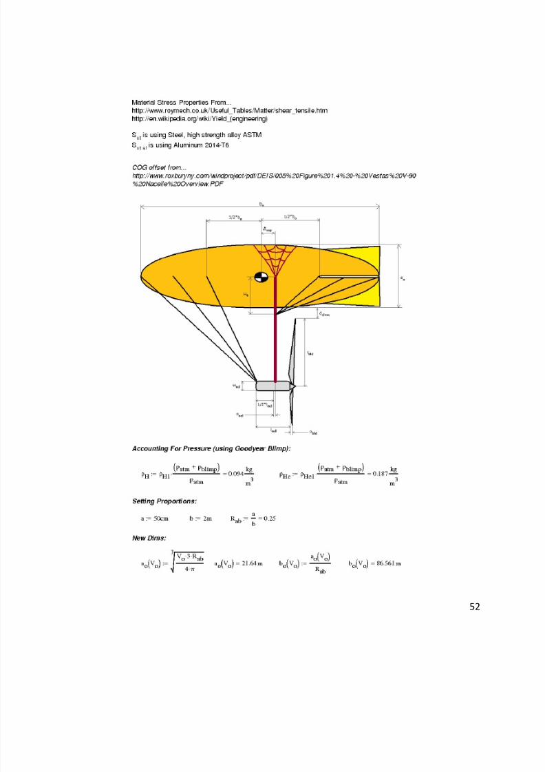
3.1 Preliminary Volume Calculations:
The gauge pressure in the Good Year Blimp was found to be around 0.7 psi. Both
hydrogen and helium were taken into account in case a company taking this design into
consideration favored the inert helium gas over hydrogen. This did not greatly affect the air
density of the medium, whether it is Hydrogen or Helium.
Mass lifted is equal to the difference in density in air from Hydrogen times the volume
(Vo). The mass of the structure was assumed by adding the mass of the turbines (Wrotor: 10
tonne; and Whub: 22 tonne) times the safety factor. Initially, it made sense to go with the
biggest turbines, but as the calculations were made, the size of the airship kept growing past
the size of the largest airship ever made, the Hindenburg. Thus, a smaller turbines design, the
850kW Vestas wind turbine, was used in the calculations. A volume was estimated initially
using the below equation.
The Hindenburg's volume is 2*105
m3, so this renewable energy airship is still
enormous, but not impossible. Keep in mind that this is still not the final calculation, but an
estimate, thus a fair amount of analysis from this point on will be functions of the volume until
Page 26
8/6/2019 Aerial Wind Turbine MQP09
http://slidepdf.com/reader/full/aerial-wind-turbine-mqp09 26/61
26
the final volume is found. From the above calculation and the ratio of length to height, the
equation of a spheroid can be used to find the height/width (ao(Vo)) and the length (bo(Vo)).
The Rab represents the 1:4 ratio (0.25) of width to length.
Figure 4: Envelope
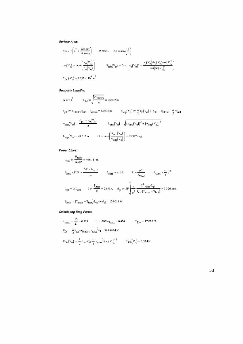
3.2 Surface Area:
The envelope was assumed to have the same thickness and material as the Goodyear
blimp. The surface area is calculated using the following formulas for prolate spheroids.
Page 27
8/6/2019 Aerial Wind Turbine MQP09
http://slidepdf.com/reader/full/aerial-wind-turbine-mqp09 27/61
27
3.3 Hanging Supports:
The next important piece of the setup is the support system. The hanging supports
consist of two rods extending from the centroid of the envelope (possibly using a netting or
other canopy-type support to connect to the envelope) to the nacelles of the turbines. Because
the width of the envelope is smaller than the sum of the radii of the blades plus a clearance
(dclrnc at 10m), this results in the two hanging supports being at obtuse angles from the
envelope.
The support in the middle, under compression, needs to account for the blade radii (rbld
at 26m) plus the clearance. The height of the support is half the height of the envelope plus the
radius of the blade plus the clearance minus half the height of the nacelle (wncl at 3m). The
horizontal distance the support spans is half of the middle support length minus half of the
envelope width. Using Pythagorean Theorem, the total length was calculated. Finally, the angle
at which the supports hang is calculated.
Page 28
8/6/2019 Aerial Wind Turbine MQP09
http://slidepdf.com/reader/full/aerial-wind-turbine-mqp09 28/61
28
Because this is facing the wind and will face a serious drag force at the end, the hanging
supports are made from a hollow rectangular cross-section to ensure high moment of inertia in
order to cut back on the bending stresses discussed further in the analysis called "Fatigue Load
on Supports".
3.4 Power Lines:
Before getting an estimate of the different drag forces, the thickness of the power lines
running up and down the tether must be considered. Because the resistance in a power line is
relative to the current squared (I2) and current directly proportional to the voltage, when the
voltage increases, the resistance significantly decreases. However, when the voltage is too
high, it may spark or lose charge through the corona effect (electron release into space when
high charge is present on small point conductors). Thus, the range in voltage for high tension
power lines was researched and found to be in the range of 3kV to 1MV. To be in that range,
but cautious, 300kV was eventually chosen to be the voltage in the power lines.
A major limiting factor in the diameter of the power lines is the amount of heat transfer.
The resistance is converted into heat, and on a sunny day, the heat from the power lines could
Page 29
8/6/2019 Aerial Wind Turbine MQP09
http://slidepdf.com/reader/full/aerial-wind-turbine-mqp09 29/61
29
melt the shielding right off. Using the equation of electrical power, the current in the power
loss equation can be found from the voltage (Ε). Equations involving power are needed to
combine electrical and heat transfer properties.
Δ T is the change in temperature from a hot day (70oC) to the melting point of rubber
(98oC). Asurf is the surface area of the wire. L is the length of the wire. "k" is the coefficient of
heat transfer for copper, as copper has high conductivity, thus optimal for electrical power
transfer. The power loss equation can be expanded knowing the R value. This is calculated
f rom the below equation where ρ is the coefficient of resistivity.
After combining the equations together, the calculated diameter is around 5.3 mm.
The total power loss (using heat transfer) is roughly 178W, which is a small fraction of the
overall power.
Page 30
8/6/2019 Aerial Wind Turbine MQP09
http://slidepdf.com/reader/full/aerial-wind-turbine-mqp09 30/61
30
3.5 Drag Force:
The “no slip” condition is a practical assumption that fluid velocity moving across a
surface will approach zero as it nears the surface. Therefore, wind velocity is small at the
ground and much larger the further away. Because of this, the aerial wind turbine must be able
to undergo drag forces from high wind velocities.
Drag is a function of velocity squared, surface area, and fluid density. Therefore, the
more area, the more drag. The most significant factor was not the surface area of the airship,
nor the surface area of the tether or cables. The largest drag force came from the area of the
turbine blades. From Betz’ Law, it states that the maximum power that a turbine can take from
the air is 16/27 (ηmax), and further research estimates that the most efficient turbines in today’s
day only reach 80% of that value, resulting in an efficiency of 47.4% (η). Thus, spinning turbine
blades only experience drag at a maximum of 47.4% from the drag on the swept area. Still, the
area swept by the blades is the most significant surface area.
From there drag from the rotor is calculated, assuming wind velocity (vmax) to be 25
meters per second, the maximum wind velocity where the turbine can operate efficiently. Also
drag on the envelope is calculated using a drag coefficient (Cd) of 0.025[28]
using an estimated
cable radius times two plus the thickness of the power lines. The cable drag assumes an
infinitely long cylinder with a drag coefficient (Cdc)of 2.1[29]
. Also, a drag force from the wing is
Page 31
8/6/2019 Aerial Wind Turbine MQP09
http://slidepdf.com/reader/full/aerial-wind-turbine-mqp09 31/61
31
estimated from a previous iteration (to be around 17 kN) and used as a variable in the overall
drag function.
The calculations show that the drag on the two rotors accounts for almost all the
horizontal force.
3.6 Area of Tether:
The tether has to be able to support the structure in heavy winds. This means that a
tether that can support the drag forces as well as the upward forces of the wing must be
attained. To do this, the drag force must be counteracted by another force equal to the drag
force divided by the cosine of the angle of the tether projecting from the ground. Using the
Pythagorean Theorem, the square root of the sum of those two forces is the overall force
pulling on the tether.
Page 32
8/6/2019 Aerial Wind Turbine MQP09
http://slidepdf.com/reader/full/aerial-wind-turbine-mqp09 32/61
32
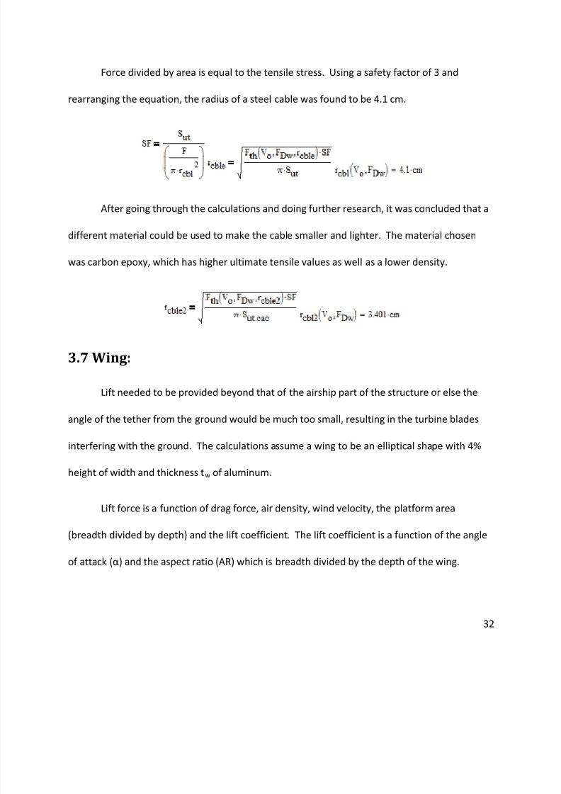
Force divided by area is equal to the tensile stress. Using a safety factor of 3 and
rearranging the equation, the radius of a steel cable was found to be 4.1 cm.
After going through the calculations and doing further research, it was concluded that a
different material could be used to make the cable smaller and lighter. The material chosen
was carbon epoxy, which has higher ultimate tensile values as well as a lower density.
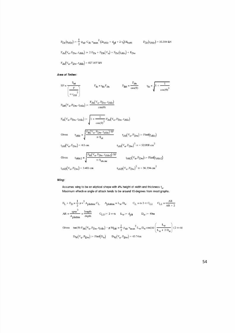
3.7 Wing:
Lift needed to be provided beyond that of the airship part of the structure or else the
angle of the tether from the ground would be much too small, resulting in the turbine blades
interfering with the ground. The calculations assume a wing to be an elliptical shape with 4%
height of width and thickness tw of aluminum.
Lift force is a function of drag force, air density, wind velocity, the platform area
(breadth divided by depth) and the lift coefficient. The lift coefficient is a function of the angle
of attack (α) and the aspect ratio (AR) which is breadth divided by the depth of the wing.
Page 33
8/6/2019 Aerial Wind Turbine MQP09
http://slidepdf.com/reader/full/aerial-wind-turbine-mqp09 33/61
33
Maximum effective angle of attack tends to be around 15 degrees from most graphs, and
beyond that, the wind foil around a wing steadily declines.
Because of the complexity involving the aspect ratio, one dimension (breadth or depth)
must be estimated first. While going through the first round of calculations, it became
apparent that a large wingspan was needed. This complicated the placement of the wings. It
would make sense to place the wing between the two nacelles, but the wing may be too deep,
reaching into the area where the turbine blades will interfere. The calculations below
demonstrate this complication.
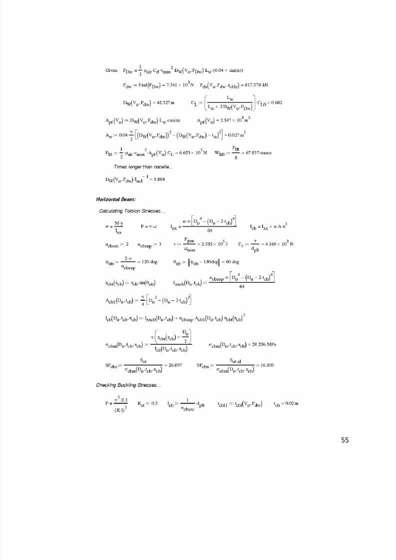
The equation to solve for the wing depth is a function of wing drag and volume. Now
that the equation is found, it can be plugged into a wing drag equation, then back into the
depth equation. This results in a wing depth 3.9 times the length of the nacelle.
Page 34
8/6/2019 Aerial Wind Turbine MQP09
http://slidepdf.com/reader/full/aerial-wind-turbine-mqp09 34/61
34
From this, the planform area is calculated at the maximum angle of attack. Also, the
cross-sectional area of the wing is calculated.
From the dimensions, it is now possible to calculate the lift coefficient and the lifting
force provided by the wing, as well as the equivalent weight it lifts in metric tonnes.
The wing is much longer than the nacelle, so the design requires further attention.
Perhaps the wings could be off the sides of the nacelle or spread out in between the supporting
rods.
Page 35
8/6/2019 Aerial Wind Turbine MQP09
http://slidepdf.com/reader/full/aerial-wind-turbine-mqp09 35/61
35
3.8 Horizontal Beam:
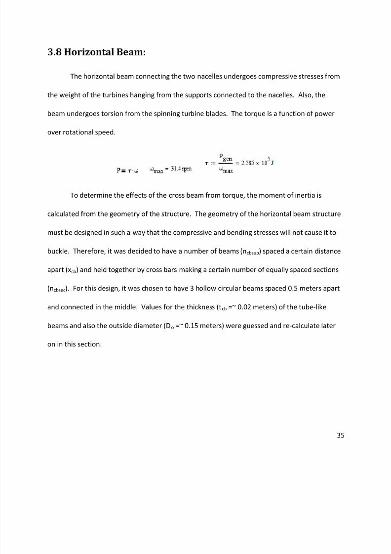
The horizontal beam connecting the two nacelles undergoes compressive stresses from
the weight of the turbines hanging from the supports connected to the nacelles. Also, the
beam undergoes torsion from the spinning turbine blades. The torque is a function of power
over rotational speed.
To determine the effects of the cross beam from torque, the moment of inertia is
calculated from the geometry of the structure. The geometry of the horizontal beam structure
must be designed in such a way that the compressive and bending stresses will not cause it to
buckle. Therefore, it was decided to have a number of beams (ncbsup) spaced a certain distance
apart (xcb) and held together by cross bars making a certain number of equally spaced sections
(ncbsec). For this design, it was chosen to have 3 hollow circular beams spaced 0.5 meters apart
and connected in the middle. Values for the thickness (tcb =~ 0.02 meters) of the tube-like
beams and also the outside diameter (Do =~ 0.15 meters) were guessed and re-calculate later
on in this section.
Page 36
8/6/2019 Aerial Wind Turbine MQP09
http://slidepdf.com/reader/full/aerial-wind-turbine-mqp09 36/61
36
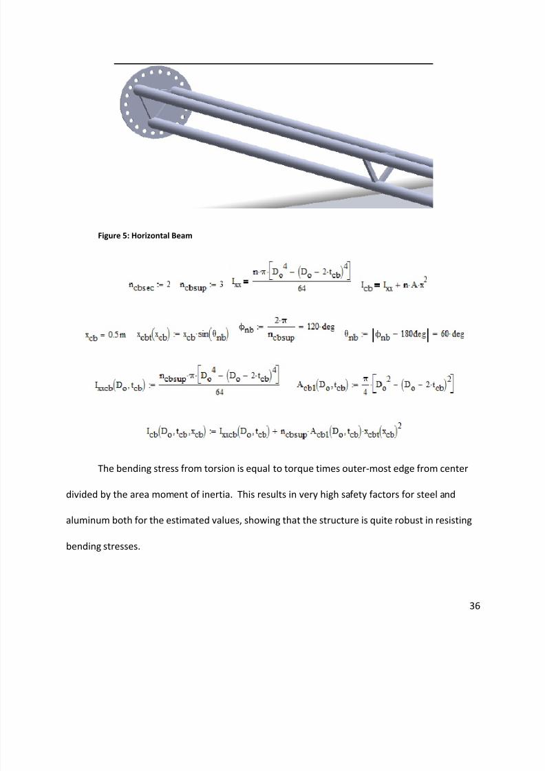
Figure 5: Horizontal Beam
The bending stress from torsion is equal to torque times outer-most edge from center
divided by the area moment of inertia. This results in very high safety factors for steel and
aluminum both for the estimated values, showing that the structure is quite robust in resisting
bending stresses.
Page 37
8/6/2019 Aerial Wind Turbine MQP09
http://slidepdf.com/reader/full/aerial-wind-turbine-mqp09 37/61
37
The biggest concern overall was not the bending stresses, but the buckling. Long beams
in compression will almost always longitudinally bend out of shape before the material snaps.
The force that could cause buckling is a function of length, area moment of inertia, a constant
(Kst = 0.5 for fixed-fixed connects), and the modulus of elasticity.
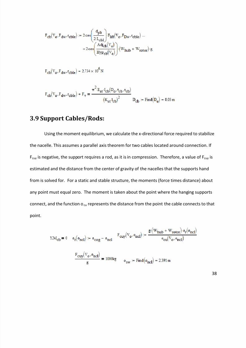
The compressive forces acting on the beam are functions of the angular geometry of the
support beams. The compressive force from the torque of the wind turbines is equal to the
torque over the length of the beam. The other compressive forces come from the tether at
high winds and also from the weight of the hub and rotor. Knowing all of the geometry, it is
possible to come up with the outer diameter.
Page 38
8/6/2019 Aerial Wind Turbine MQP09
http://slidepdf.com/reader/full/aerial-wind-turbine-mqp09 38/61
38
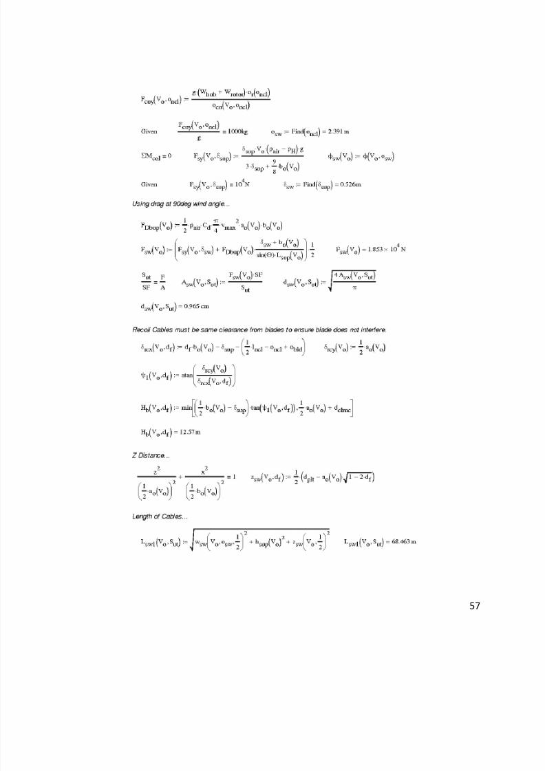
3.9 Support Cables/Rods:
Using the moment equilibrium, we calculate the x-directional force required to stabilize
the nacelle. This assumes a parallel axis theorem for two cables located around connection. If
Fcuy is negative, the support requires a rod, as it is in compression. Therefore, a value of Fcuy is
estimated and the distance from the center of gravity of the nacelles that the supports hand
from is solved for. For a static and stable structure, the moments (force times distance) about
any point must equal zero. The moment is taken about the point where the hanging supports
connect, and the function ocu represents the distance from the point the cable connects to that
point.
Page 39
8/6/2019 Aerial Wind Turbine MQP09
http://slidepdf.com/reader/full/aerial-wind-turbine-mqp09 39/61
39
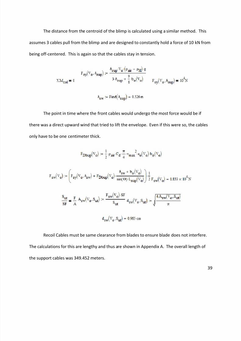
The distance from the centroid of the blimp is calculated using a similar method. This
assumes 3 cables pull from the blimp and are designed to constantly hold a force of 10 kN from
being off-centered. This is again so that the cables stay in tension.
The point in time where the front cables would undergo the most force would be if
there was a direct upward wind that tried to lift the envelope. Even if this were so, the cables
only have to be one centimeter thick.
Recoil Cables must be same clearance from blades to ensure blade does not interfere.
The calculations for this are lengthy and thus are shown in Appendix A. The overall length of
the support cables was 349.452 meters.
Page 40
8/6/2019 Aerial Wind Turbine MQP09
http://slidepdf.com/reader/full/aerial-wind-turbine-mqp09 40/61
40
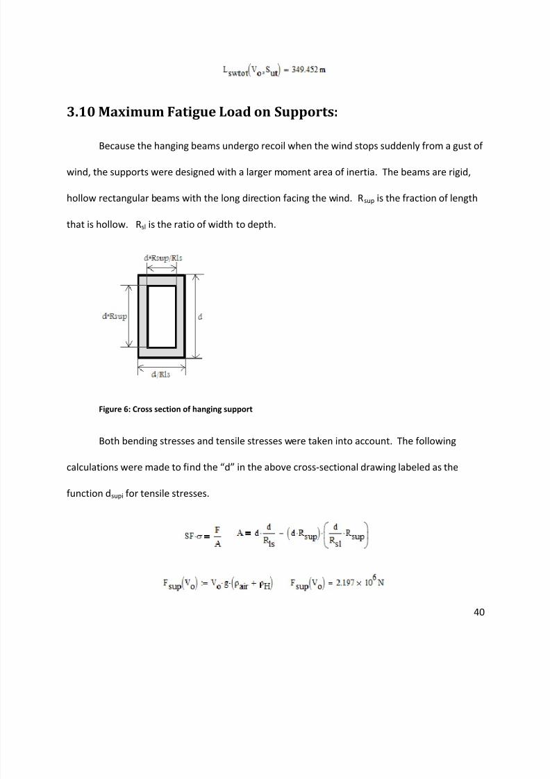
3.10 Maximum Fatigue Load on Supports:
Because the hanging beams undergo recoil when the wind stops suddenly from a gust of
wind, the supports were designed with a larger moment area of inertia. The beams are rigid,
hollow rectangular beams with the long direction facing the wind. Rsup is the fraction of length
that is hollow. Rsl is the ratio of width to depth.
Figure 6: Cross section of hanging support
Both bending stresses and tensile stresses were taken into account. The following
calculations were made to find the “d” in the above cross-sectional drawing labeled as the
function dsupi for tensile stresses.
Page 41
8/6/2019 Aerial Wind Turbine MQP09
http://slidepdf.com/reader/full/aerial-wind-turbine-mqp09 41/61
41
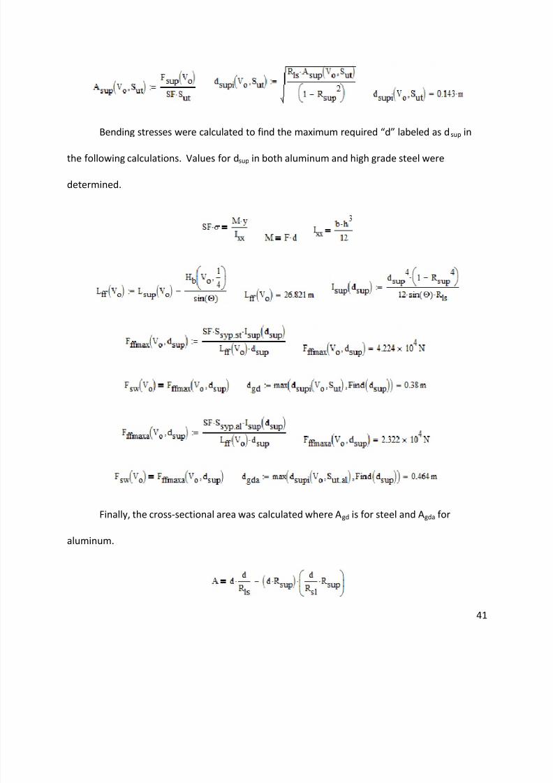
Bending stresses were calculated to find the maximum required “d” labeled as d sup in
the following calculations. Values for dsup in both aluminum and high grade steel were
determined.
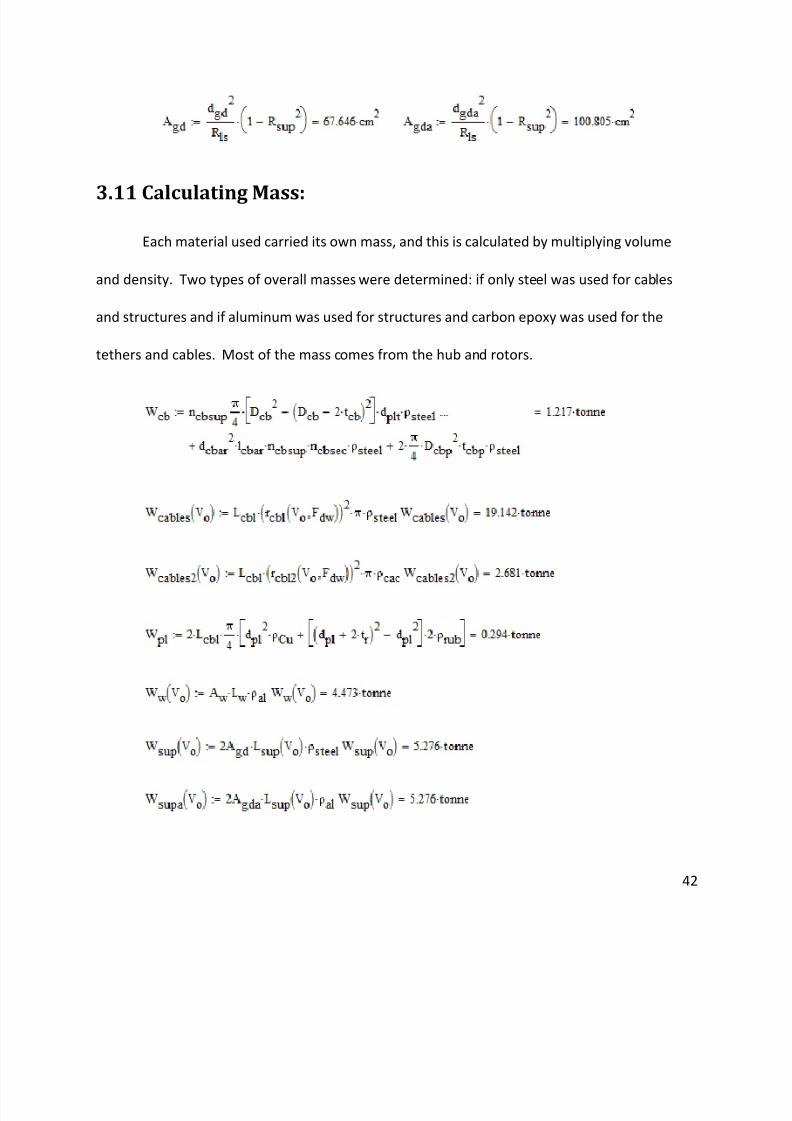
Finally, the cross-sectional area was calculated where Agd is for steel and Agda for
aluminum.
Page 42
8/6/2019 Aerial Wind Turbine MQP09
http://slidepdf.com/reader/full/aerial-wind-turbine-mqp09 42/61
42
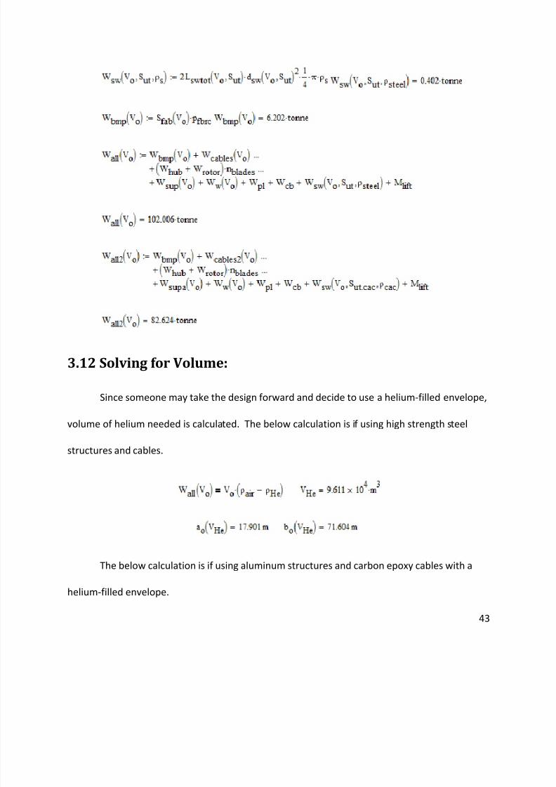
3.11 Calculating Mass:
Each material used carried its own mass, and this is calculated by multiplying volume
and density. Two types of overall masses were determined: if only steel was used for cables
and structures and if aluminum was used for structures and carbon epoxy was used for the
tethers and cables. Most of the mass comes from the hub and rotors.
Page 43
8/6/2019 Aerial Wind Turbine MQP09
http://slidepdf.com/reader/full/aerial-wind-turbine-mqp09 43/61
43
3.12 Solving for Volume:
Since someone may take the design forward and decide to use a helium-filled envelope,
volume of helium needed is calculated. The below calculation is if using high strength steel
structures and cables.
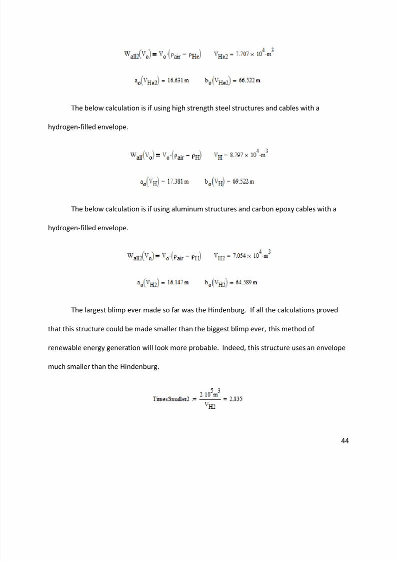
The below calculation is if using aluminum structures and carbon epoxy cables with a
helium-filled envelope.
Page 44
8/6/2019 Aerial Wind Turbine MQP09
http://slidepdf.com/reader/full/aerial-wind-turbine-mqp09 44/61
44
The below calculation is if using high strength steel structures and cables with a
hydrogen-filled envelope.
The below calculation is if using aluminum structures and carbon epoxy cables with a
hydrogen-filled envelope.
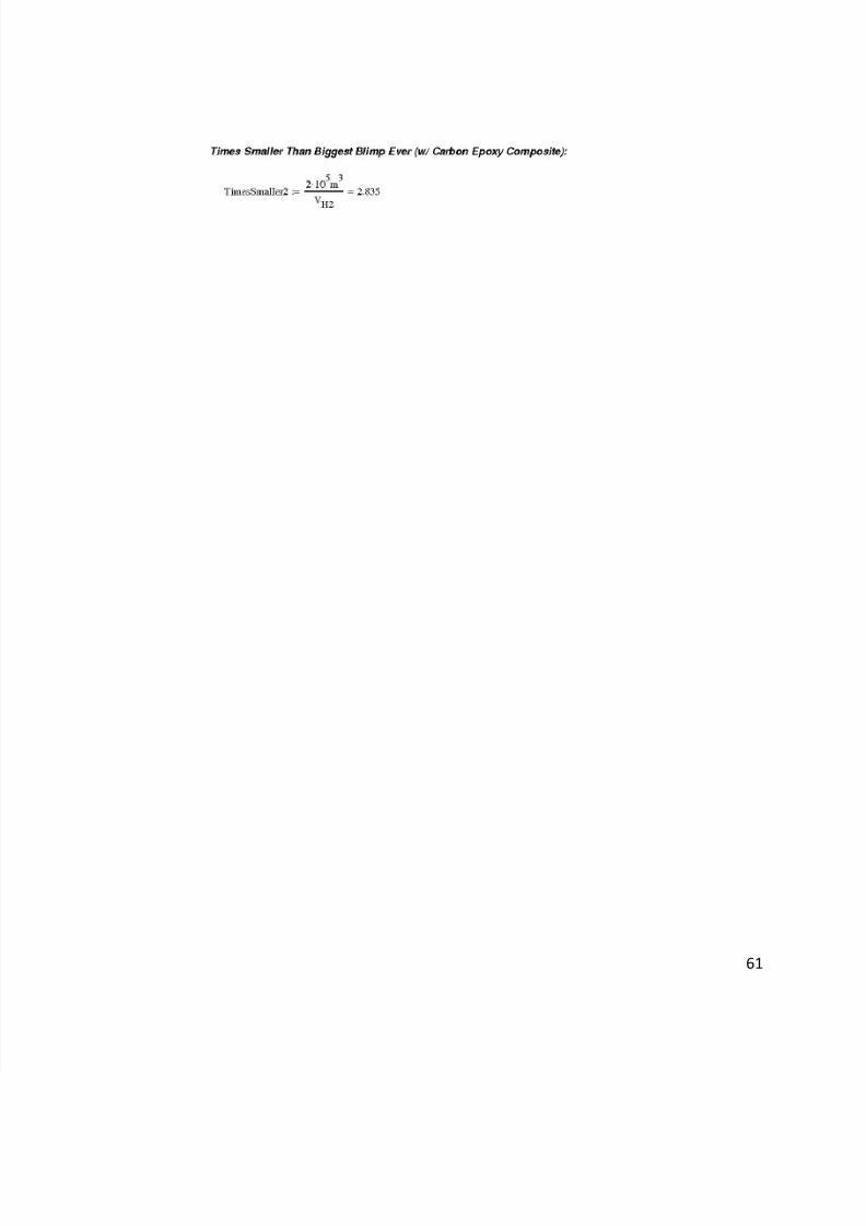
The largest blimp ever made so far was the Hindenburg. If all the calculations proved
that this structure could be made smaller than the biggest blimp ever, this method of
renewable energy generation will look more probable. Indeed, this structure uses an envelope
much smaller than the Hindenburg.
Page 45
8/6/2019 Aerial Wind Turbine MQP09
http://slidepdf.com/reader/full/aerial-wind-turbine-mqp09 45/61
45
4.0 Conclusions/Future Work:
After researching this design, conclusions were made and ideas for future work came
about. From the calculations, the major finding is that at the present time this project is
feasible but will be challenging to complete. One reason for this conclusion is the size and
weight of the turbines. The weight of the turbines and the drag forces cause the blimp to be
massive in size. This project can be undertaken but in the future there are specific challenges
that should be solved in order to have an upgraded prototype.
During our calculations for determining the forces on the structure we came up with
some ideas for future development. Our first idea is to change the shape of the blimp. In the
present design the blimp is the normal elliptical shape and we believe that if the blimp could be
shaped as an airfoil, it could create its own lift. With our design, there needs to be a big wind
added to create the extra lift needed. The placement of the wing is between the two turbines.
We believe that if you could change the placement of the wing, attached to the sides of the
blimp for example, it would create a pulling force up which might be more effective. We chose
to use steel cables connecting the turbines to the blimp for our design. These cables are strong
but they also weigh a lot. To lighten the load, it would be a better idea to use a different
material for the cables. During our research we found a carbon-epoxy material that was both
stronger and lighter than steel. The original design was conceived to be tethered at a 30 degree
angle to the ground. After numerous calculations, it was determined that the optimal tethering
angle should be approximately 60 degrees to minimize the force of the cable on the blimp.
Page 46
8/6/2019 Aerial Wind Turbine MQP09
http://slidepdf.com/reader/full/aerial-wind-turbine-mqp09 46/61
46
Another aspect of the design that could be further looked into would be testing a model
of this prototype to see how it might fair in extreme wind conditions. Calculating the forces on
components of the structure will not give the full picture of how prototype might respond to
stormy conditions. An example of this would be testing the torques caused by the spinning
blades of the turbine. The blades will create a bending stress on the entire cross beam
between the nacelles. These values can be obtained through experimentation to see if the
beam fails and causes the whole structure to break. Also, there was a certain angle of the
tethering that we figured out would be needed to keep the turbines aligned directly into the
wind and a finished design would not be plausible without evaluating models. Testing a model
to failure would also help to see where the weakest links of the structure are. If you can
strengthen those weak links, then you can come up with a prototype that will have a much
longer life span. The ability to see how the structure is affected by the different forces
associated with swirling winds is of great importance in confirming what the calculations show.
Taking a turbine designed to sit atop a tower of no more than 100m and placing it
hanging from a blimp upwards of 300m in the air could greatly affect the efficiency of the
turbine itself. Designing a turbine specifically for high altitude use is crucial in obtaining the
most efficient model for extracting power from high altitude winds. This could mean only
changing some of the components to get a lighter overall weight but could also involve
changing features in the turbine that constantly adjust the pitch of the blades. No companies
Page 47
8/6/2019 Aerial Wind Turbine MQP09
http://slidepdf.com/reader/full/aerial-wind-turbine-mqp09 47/61
Page 48
8/6/2019 Aerial Wind Turbine MQP09
http://slidepdf.com/reader/full/aerial-wind-turbine-mqp09 48/61
48
limit in which it will theoretically never fail under certain repetitive load size. The high the
grade of steel used, the less likely it is to fail and a lesser amount of material can be used to
support the structure.
Page 49
8/6/2019 Aerial Wind Turbine MQP09
http://slidepdf.com/reader/full/aerial-wind-turbine-mqp09 49/61
49
Works Cited
1) High Altitude Wind Power. Bryan Roberts. December 2008. Sky WindPower Corporation.
November 19 2008 <http://www.skywindpower.com/ww/index.htm>.
2) Twidell, J., 2003, “Technology Fundamentals Wind Turbines,” Renewable Energy World, pp.
102-111
3) Walker James February 5 2009, American Wind Energy Association. January 15 2009
<http://www.awea.org/>
4) Wackenmagel and Rees. 1996. “Our Ecological Footprint.” New Society Publishers.1998
5) Dodge, D., 2006, “Illustrated History of Wind Power Development,” Telos Net Web
Development, Littleton, Colorado
6) Vestas. Feb 2009. Vestas Wind Systems December 2008 <http://www.vestas.com/en>
7) GE Energy, 2009 “1.5 MW Wind Turbine Technical Specifications.” Fairfield, CT
8) Gamesa. January 2009. Gamesa Technology Corporation. November 10 2001
<http://gamescorp.com/en/gamesa>
9) Richard, G.R., Feb 2008, “Enercon E-126: The World’s Largest Wind Turbine.” Treehugger
Discovery Communications. New York, NY.
10) RE Power. Feb 2009 RE Power Systems. November 2008. Hamburg, Germany.
<http://www.repower.de/index>
11) Suzlon. Feb 2009. Suzlon Energy. November 15, 2008
<http://www.suzlon.com/Home.aspx>
12) Siemens. Feb 2009. Siemens Energy. November 2008
<http://www.powergeneration.siemens.com/home/>
13) World Wind Energy Report 2008. April 2009. World Wind Energy Association.
<http://www.wwindea.org/home/images/stories/worldwindenergyreport2008_s.pdf>.
14) Wind Energy. 2007. European Renewable Energy Council. February 2009
<http://www.erec.org/renewableenergysources/wind-energy.html>.
15) Free Patents Online. January 2009. November 19 2008
<http://www.freepatentsonline.com/>.
16) “Zeppelin NT,”Wikipedia.com, April 5, 2009.
Page 50
8/6/2019 Aerial Wind Turbine MQP09
http://slidepdf.com/reader/full/aerial-wind-turbine-mqp09 50/61
50
17) Goodyear Blimp. 2006 The Goodyear Tire and Rubber Company. January 2009. Akron, Ohio.
<http://www.goodyearblimp.com>
18) Magenn Power Air Rotor System. Fred Ferguson. October 2008. Magenn Power. November
21 2008 <http://magenn.com/index.php>.
19) World Energy Outlook. February 2009. International Energy Agency. December 10 2008
<http://www.worldenergyoutlook.org/index.asp>.
20) LadderMill. Wubbo Ockels. September 2 2003. Delft University of Technology. December 2
2008 <http://www.ockels.nl/>.
21) Windfair. Martin Tschierschke. January 2009. December 12 2008
<http://windfair.net/welcome.html>.
22) Rosenbloom, E., 2009 “Size Specifications of Common Industrial Wind Turbines.”
Alternative Wind Energy Outlook. Vermont
23) Brain, M., 2009, “How Helium Balloons Work.” How Stuff Works. Atlanta, GA.
24) Sussman, P., 2007 “Reach for the Sky: Could flying wind farms help beat global warming?”
CNW. London, England.
25) Vahrenholt, F. 2005. “Germany Inaugurates 5 MW Wind Prototype.” Renewable Energy
Access. Hamburg, Germany.
26) Enercon. Feb 2009. Enercon Company. November 10 2008
<http://www.enercon.de/en_home.htm>
27) Wind Energy. 2009 Intelligent Energy. January 2009 <http://www.wind-energy-the-facts.org/>
28) Glenn Elert. “Aerodynamic Drag”. April 2009.
<http://hypertextbook.com/physics/matter/drag/>
29) “Drag Fluids”. April 2009. <http://www.roymech.co.uk/Related/Fluids/Fluids_Drag.html>
Page 51
8/6/2019 Aerial Wind Turbine MQP09
http://slidepdf.com/reader/full/aerial-wind-turbine-mqp09 51/61
51
Appendix A:
Page 52
8/6/2019 Aerial Wind Turbine MQP09
http://slidepdf.com/reader/full/aerial-wind-turbine-mqp09 52/61
52
Page 53
8/6/2019 Aerial Wind Turbine MQP09
http://slidepdf.com/reader/full/aerial-wind-turbine-mqp09 53/61
53
Page 54
8/6/2019 Aerial Wind Turbine MQP09
http://slidepdf.com/reader/full/aerial-wind-turbine-mqp09 54/61
54
Page 55
8/6/2019 Aerial Wind Turbine MQP09
http://slidepdf.com/reader/full/aerial-wind-turbine-mqp09 55/61
55
Page 56
8/6/2019 Aerial Wind Turbine MQP09
http://slidepdf.com/reader/full/aerial-wind-turbine-mqp09 56/61
56
Page 57
8/6/2019 Aerial Wind Turbine MQP09
http://slidepdf.com/reader/full/aerial-wind-turbine-mqp09 57/61
57
Page 58
8/6/2019 Aerial Wind Turbine MQP09
http://slidepdf.com/reader/full/aerial-wind-turbine-mqp09 58/61
58
Page 59
8/6/2019 Aerial Wind Turbine MQP09
http://slidepdf.com/reader/full/aerial-wind-turbine-mqp09 59/61
59
Page 60
8/6/2019 Aerial Wind Turbine MQP09
http://slidepdf.com/reader/full/aerial-wind-turbine-mqp09 60/61
60
Page 61
8/6/2019 Aerial Wind Turbine MQP09
http://slidepdf.com/reader/full/aerial-wind-turbine-mqp09 61/61