10
INSTALLATION GUIDE PREMIUM FRONT BUMPER AEV30103AE Last Updated: 09/08/14 US PATENTS: D683281, D697842 CHINESE PATENT: ZL 2012 3 0026081.4
INS
TALL
ATIO
N G
UID
E
P R E M I U M F R O N T B U M P E R
AEV30103AELast Updated: 09/08/14
US PATENTS: D683281, D697842 CHINESE PATENT: ZL 2012 3 0026081.4

PLEASE READ BEFORE YOU STARTTO GUARANTEE A QUALITY INSTALLATION, WE RECOMMEND READING THESE INSTRUCTIONS THOROUGHLY BEFORE BEGINNING ANY WORK. THESE INSTRUCTIONS ASSUME A CERTAIN AMOUNT OF MECHANICAL ABILITY AND ARE NOT WRITTEN NOR INTENDED FOR SOMEONE NOT FAMILIAR WITH AUTO REPAIR.
ii
This product is covered under the AEV Parts Limited Warranty, a copy of which can be found at aev-conversions.com/warranty.
INCLUDED PARTS QTY REQUIRED TOOLS
Premium Front Bumper 1 Common Hand ToolsFairlead Bracket 1 Drill Motor
Closeout Brackets 2 Drill BitsFog Light Brackets 2 Transfer or Center PunchTow Loop Brackets 2 Cut Off Wheel (2010+ Only)Mesh Inserts 2 Touch Up Paint or Rust InhibitorCrush Can Covers 2 File or De-burring ToolHardware Pack 1

1
I. Remove factory componentsA. Remove the factory air dam1. Remove the “Scrivet” fasteners at the front and back side of the air dam. Use a Phillips screwdriver
to back out the plastic pin and pull out the fastener. The pin will tend to spin. Use a flat screwdriver under the base of the fastener to apply pressure as you turn the screw. Do not discard these fasten-ers. You will re-use two of them later on.

2
B. REMOVAL OF THE FRONT BUMPER1. If you have fog lights disconnect the wiring.
2. Remove the and discard the 8 nuts attaching the bumper to the frame rails.
3. Remove and discard steel backing plates from inside frame rail.
4. Carefully remove BUT DO NOT DISCARD the plastic filler panel in front of the grill. If installing a winch, you will trim this piece and re-use it later. You will also need 2 scrivets.

3
II. VEHICLE PREPERATIONA. MODIFY FOG LIGHT WIRING FOR PREMIUM BUMPER ONLY(NOTE: 2007-2009 USA, CANADA, AND MEXICO MODELS ONLY)
1. The fog lights are mounted further apart than factory, so the wiring harness needs to be re-posi-tioned. This is accomplished by removing the factory conduit and re-routing the harness above the frame rails. BE CAREFUL NOT TO CUT THE HARNESS!
2. Remove the tape from the wire harness at both ends to expose the loose length of wires.
3. Extend the harness outboard as much as possible to reach the new fog light location.
4. Replace the conduit, if it has been removed, and re-tape the modified harness.
5. Route the harness along the bottom of the grille and fasten to power steering line using cable ties.
Original Wiring Position Remove Tape

4
B. MODIFY FOG LIGHT WIRING FOR PREMIUM BUMPER ONLY(NOTE: 2010+ USA, CANADA, AND MEXICO MODELS ONLY)
1. Remove the tape from the wire harness on the right side only to expose the loose length of wire. Should have approximately 7”.
2. Replace the conduit, if it has been removed, and re-tape the modified harness.
3. Route the harness along the bottom of the grille and fasten to the power steering line using cable ties.
New Harness Length Fasten to Power Steering Line

5
III. INSTALL BUMPER KITA. TOW LOOP BRACKET INSTALLATION
1. Place tow loop bracket on the vehicle frame.
2. Slide the nut plate into the frame and loosely install the M12 hex head bolts to align tow loop.
3. NOTE: NEWER 2012 VEHICLES HAVE THE FRONT MOUNTING HOLE IN THE FRAME FROM THE FAC-TORY. PROCEED TO STEP 6.
4. If the front mounting hole is not in the frame, push the tow loop bracket up as far as it will go and snug the side mounting bolts to hold it into place. Then using a transfer or center punch mark the location on the frame for the front attachment point.
5. Remove the tow loop and drill with a 1/2” drill bit where marked. It helps to drill a 1/8” pilot hole first.
6. De-burr the drilled hole and paint with a corrosion inhibitor or touch up paint.
7. Place the tow loop bracket back into place and install M12 hex head bolt with washer into the front attachment point.
8. You will also need to place a 1/2” washer between the tow loop bracket and frame at this point to ensure a flat mounting surface.
9. Install the closeout bracket to the tow loop using M12 hex head bolts with washers and nut plate.

6
B. WINCH PLATE InstallationIf you are installing an AEV Winch Mount with your Premium Front Bumper you may now refer to the In-struction Sheet included with the Winch Mount Kit.
C. MODIFY FACTORY BUMPER FILLER TRIM PANELThe factory filler panel is left in place to hide the frame rails and other underbody components. How-ever, it will be necessary to trim the panel if you are installing a winch. The following steps illustrate how to trim the panel to fit a Warn 9.5cti style winch. Because there are many different winches on the market your trim may vary. You can use different tools for this job. A reciprocating saw with a metal cutting blade will work fine. An air saw or hand saw will also work as well. Clean up the edges using sand paper or razor knife.
1. Start by cutting the filler panel as shown below. Insert your saw and cut through the 5 center slots. This will give you a good starting point for most winch profiles. This trim will provide approximately 16” of width. Measure the main body of your winch and adjust this as necessary.
2 inches
2 inches
2. Next make additional cuts to accommodate the ends of the winch. The images below show the necessary trim for the Warn 9.5cti.
2 inches
2 inches
2 inches
2 inches
3. Verify the trim panel clearance to the winch and re-install using the factory scrivets saved from disassembly.

7
D. Premium Bumper Installation
1. Install the mesh into the bumper over the studs and tighten M6 flange nuts.
2. Install the crush can covers with M6 hex head bolts with washers.
3. If you are not installing the winch plate temporarily attach the fairlead bracket to the bumper. Attach through the center set of holes used for mounting a roller/hawse fairlead with two of the supplied M12 hex head bolts and flange nuts.
4. Install the light mount brackets with M10 button head bolts, washers, and nuts.
5. Using the assistance of a helper carefully set the bumper on the vehicle. BE CAREFUL NOT TO SCRATCH THE GRILLE, PLASTIC FENDER FLARES, OR WINCH.
6. Insert the (8) M12 button head fasteners with washers through the bumper, fairlead bracket, and frame rails.
7. NOTE: THE SHORT M12 BUTTON HEAD BOLT SHOULD BE USED IN THE RIGHT SIDE UPPER MOST INNER LOCATION. USING A LONG BOLT HERE WOULD INTERFERE WITH THE WINCH MOTOR.
8. While holding the bumper in place use the flange nuts in all locations except on the short button head bolt, which uses a thin Jam nut. Tighten the (8) button head fasteners enough to allow align-ment.
8
9. Remove the two bolts temporarily holding the fairlead bracket to the bumper if the winch plate was not installed.
10. Loosely attach the closeout brackets to the backside of the bumper with M10 hex head bolts, washers, and flange nuts. The bolts should be installed from the inside of the bumper out.
11. Adjust the bumper to line up with the fairlead bracket and slowly tighten the (8) button head fasteners making sure the bumper is vertical and flat against the fairlead bracket.
12. After the face bolts are tight you can tighten the M10 fasteners.
13. Tighten the M12 bolts to fasten the closeout brackets to the frame.
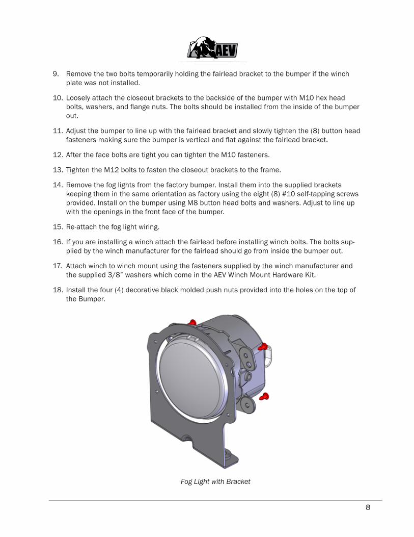
14. Remove the fog lights from the factory bumper. Install them into the supplied brackets keeping them in the same orientation as factory using the eight (8) #10 self-tapping screws provided. Install on the bumper using M8 button head bolts and washers. Adjust to line up with the openings in the front face of the bumper.
15. Re-attach the fog light wiring.
16. If you are installing a winch attach the fairlead before installing winch bolts. The bolts sup-plied by the winch manufacturer for the fairlead should go from inside the bumper out.
17. Attach winch to winch mount using the fasteners supplied by the winch manufacturer and the supplied 3/8” washers which come in the AEV Winch Mount Hardware Kit.
18. Install the four (4) decorative black molded push nuts provided into the holes on the top of the Bumper.
Fog Light with Bracket


