|4 AFAPL-TR- 76-48 Volume 1i $ 4~. INVESTIGATION OF ROTATING STALL PHENOMENA IN AXIAL FLOW COMPRESSORS Volume Il - INVESTIGATION OF ROTOR- STATOR INTERACTION NOISE AND LIFTING C SURFACE THEORY FOR A ROTOR •'V') CALSPAN CORPORATION P.O. BOX 235 BUFFALO, NEW YORK 14221 JUNE 1976 TECHNICAL REPORT AFAPL-TR-76-48 Volume II FINAL REPORT FOR PERIOD 1 MAY 1973 - 31 MAY 1976 SApproved for public release; distribution unlimited AIR FORCE AERO-P1ROPULSION LABORATORY AIR FORCE WRIGHT AERONAUTICAL LABORNIORIES AIR FORCE SYSTEMS COMMAND WRIGITT-PATTERSON AIR FORCE BASE, GITIO -45433
Transcript
|4
AFAPL-TR- 76-48
Volume 1i $ 4~.
INVESTIGATION OF ROTATING STALLPHENOMENA IN AXIAL FLOW COMPRESSORSVolume Il - INVESTIGATION OF ROTOR-STATOR INTERACTION NOISE AND LIFTING
C SURFACE THEORY FOR A ROTOR
•'V') CALSPAN CORPORATION
P.O. BOX 235BUFFALO, NEW YORK 14221
JUNE 1976
TECHNICAL REPORT AFAPL-TR-76-48 Volume IIFINAL REPORT FOR PERIOD 1 MAY 1973 - 31 MAY 1976
SApproved for public release; distribution unlimited
AIR FORCE AERO-P1ROPULSION LABORATORYAIR FORCE WRIGHT AERONAUTICAL LABORNIORIES
AIR FORCE SYSTEMS COMMANDWRIGITT-PATTERSON AIR FORCE BASE, GITIO -45433
NOIC
Men Governmn•t drawings, specifications, or other data are uscdfor any purpose other than in connection with a definitely relatedCoverrumit procurenrnt operation, the United States Government therebyincurs no responsibility nor any obligation whatsoever; and the factthat the government may have formulated, furnished, or in any waysupplied the said drawings, specifications, or other data, is not tobe regarded by inplication or otherwise as in any manner licensing theholder or any other person or corporation, or conveying any rights orpermission to manufacture, use, or sell any patented invention that nmyin any way be rlated thereto.
Tnis final report was sut•nitted by the Calspan Corporation, tuderContract F33615-73-C-.2046. The effort was sponsored by the Air ForceAero-Propulsion Laboratory, Air Force Systzsi CcTnand, Wright-PattersonAFB, Ohio under Project 3066, Task 306603, and Work Unit 30660334 withMr. Marvin A. Stibich, AFAPIA/B2, as Project Engineer in charge.Dr. Gary R. L'xlwig of the Calspan Corporation was technically responsi-ble for the work.
This report has been reviewqed by the Information Office, ASD/OIP,and is releasable to the National Technical Information Service (NTIS).At NTIS, it -will be available to the general public, including foreign
This technical report has been reviewed and is approved for publi-cation.
NURVIN F. SCRHMII' "-Z., , /tTech Area Manager, Crpnresson3 1"
Copies of this report should not be returned unless return isrequired by security ornsiderations, contractual obligations, or noticeon a specific docuno•t,A; Oct - 1Ii 6JO 76 - t0o
UNUILqS IP]CD11St.LCjVMI T y CLASSIf I CAl N I 140 1 115 P A L I(41-," F) I "1 d
REF,%T-DOCUMENTATION PAGE Pi- 0 (D INSTRUCIONSf f
TýT~ -2 G OV T A.C C rSS I GN N O . 3 R E C IP IE N T 'S rA T A L O G ~ i U -
1rA½212R-A7 6_-4 8 -V 4W14 T. 5 TYPLOF RELPORT AS PERIOD COVIERED
action Nossl tiW-'D 'lioyfor a Potorp XE-5319-A--12 ___
AU5Tirr! A ACT oR GAfe
Joh)Iln A.In i5 4 I7
Grecy,_________ j. F336l5-73-C-2O460'
Calsjxin Corporation .-- /P1. 0. Box 2-35Buflo c York 14221 33,&6043
ICGNS IROL LIN4S OF F ICFI NAME AND ADDRIFESS, RE* 0=A
U.S. Air Fore Aero-Propulsion LaboiftoryAir Force Systcmts Conxrnnd NMr
WrightL-Patterson AMB, oil 45423 _Js r..eMO4N I TORIN G AQýENCY N4 AML IL AOIDDESSCI d,(Ip-,, f,o-n OM,~nn l) 1S SE.C RI LL mf ut )
Unclassif iodIS5. D-ECL ASSI FICATON DOANGRAGINO
SCHEýDULIE
16 DISTRIBU71iON STATEME.NT 'o.f rln krnI
71 V
I , K E ....S...../-I b ..- k "MI.-)
RO-t. i ____ I Stall I'i _____ ______________
IA. SuI'P IJLNT v ANY OTE
29 5 KE ROG A ' CI.e 1, VCV1,14 lid, Ifnt #Il -ar Wi,I ) ,IIII In- h ýck vtn I's
iis re] cti presents the,_ rc(Sulj~tr of a research 'rogramn Uiat had tiwc majorObjectives'. ¶1W.: first. objectiwvewnq the1 developuuimi of a prototype rotatingstall control01 systen, whic-h was tested Wutn on a locw speud rig and a J-85-5e~ngine. Thic eSc%)jIII olbjuclivc( was to perform bJudiCiifltal stiidjif_ of the flowrxhchian~ ais t~hat pro.duce i-olaf ing staill, surge and noise i .1 axial flow ctnrelrssorsand thtereby obtaini an understaniding of these phjen~onuna th.;t w.ould aid. attainingthr' first al-jctive. TheC W~rk is reported in thiree sepatrotc voluxrts. Volwiz 1
I)D 14/73 PIOIN01 OF I NOV 65 IS OBSGLETE JL1~PaSELMINt V CL ASSIFICAS ION OFTlSPGEIheft.I/e)
. .- ------- AAiWLt..NLI
UNCLAKSS IFJ-EDSECJ.RQITyY CLASSIFICATION OF " H!s A GECR I Pu .001 a E.-11? areJ)
20. (Cont'd)
covWs the funduwental theoretical and expTrimrntal studios of rotating stall;Volute II covers the theoretical Erid e4•erim.rintal studies of discrete-roneaerTxynanic noise generation mechaism6 in axial flow, compressors; and VolumeI ovenr the developxrent and testing of a prototype rotating stall controlsystem on both the low .peed test rig and the J-85-5 engine.
UNCIASSMII)SECUPITY CLAISIFICAT6ON or flhlS PAGE(TIHI, S r nf~red)
FOImP RD
This is the final Technical Report prepared by the Calspan
Corporation. Mhe effort was sponsored by the Air Force Aero-
Propulsion LAnIratory, Air F1rce Systems Coamrund, Wright-Patterson
AFB, Ohio under Contract F33615-73-C-2046 for the period 1 May 1973
to 31 May 1976. The work herein was accoxplished under Project 3066,
Task 306603, Work Unit 30660334, "Investigation of Rotating Stall
Pheriena in Axial Flow Comuressors," with Mr. Marvin A, Stibich,
AFAPL4/TBC, as Project Engineer. Dr. Gi-ry R. Ludwig of the Calspan
Corporation was technical, .nrsible for the work. Other Calspan
personnel were: Joseph P. M-kini, Joan C. Erickson, John A. Iordi,
Gregory F. Hlomicz, and Rudy I1. Arendt.
i.;
ABSTRACT
Th•is report presents the results of a research program that had two
major objectives. The first objective was the development of a prototype
rotating stall control system which was tested both on a low speed rig and a
J-85-5 engine. The second objective was to perform fundamental studies of the
flow mechanisms that produce rotating stall, surge and noise in axial flow
compressors and thereby obtain an understanding of these phenomena that would
aid attaining the first objective. The work is reported in three separate
volumes. Volume I covers the fundamental theoretical and experimental studies
of rotating stall; Volume II covers the theoretical and experimental studies of
discrete-tone aerodynamic noise generation mechanisms in axial flow compressors;
and, Volume III covers the development and testing of a prototype rotating stall
control system on both the low speed test rig and&the J-85-5 engine.
Volume I describes the theoretical and experimental investigation of
the influence of distortion on the inception and properties of rotating stall
for an isolated rotor row, and the effects of close coupling of a rotor and
stator row on rotacing stall inception. The experiments were conducted in the
Calspan/Air Force Annular Cascade Facility, which is a low speed compressor
research rig. In addition, the previously developed two dimensional stability
theory for prediction of inception conditions was extended to include the
effect of compressibility and the development of a three dimensional theory
was initiated. These studies led to the following key results. The experi-
mental studies of distortion show that for a single blade row the response of
the blade row to the distortion and rotating stall are uncoupled phenomena and
may be explained on the basis of a linearized analysis. The experimental
studies of a closely coupled rotor-stator pair show that the addition of a
closely spaced stator row downstream of a rotor row delays the onset of rotating
stall. Moreover, the corresponding theoretical analysis predicts this trend
although quantitative agreement is hampered by the lack of appropriate steady-
state loss and turning performance for each blade row at the required operating
conditions. The theoretical investigation of the effects of compressibility
for wholly subsonic flows outside the blade rows indicates that the effects of
iii
compressibility do not alter the mechanisms of rotating stall as deduced from
the incompressible theory in that the rate of change of the steady state loss
curve with inlet swirl is the dominant blade row characteristic affecting its
stability. Therefore, if the steady state losses are known for the compressible
flow condition, the lineaiized stability analysis is expected to apply.
Volume II describes a theoretical and experimental study of discrete-
tone noise generation by the interaction of a rotor and a stator, and the de-
velopment of a direct lifting surface theory for an isolated rotor. An approxi-
mate model has been developed to predict the sound pressure level and total
power radiated at harmonics of the blade passage frequency for a rotor-stator
stage. The analysis matches the duct acoustic modes for an annular duct with
an approximate representation of the unsteady blade forces which includes com-
pressibility effects. Measurements were made of thle sound pressure levels
produced on the duct wall of the annular cascade facility by a rotor-stator
pair. Predictions which indicated that only the fourth and higher harmonics
could be excited at conditions achievable in the facility, were borne out by
the experiments. The calculations of the sound pressure levels for the propa-
gating modes were significantly below the measured values. This discrepancy
is believed to result from inaccuracies in existing models of rotor wake
velocity profiles, which are shown to have a strong influence on predictions
of the sound pressure levels of the higher harmonics. Volume II also contains
the formulation of a direct lifting surface theory for the compressible,
three-dimensional flow through a rotor row in an infinitely long annular duct.
A detailed derivation is given for the linearized equations and Uhe corres-
ponding solutions for the blade thickness and loading contributions to the
rotor flow field. The governing integral equation for the blade loading in a
lifting surface theory is obtained for subsonic flow and progress on its
solution is reported.
Volume III describes the development and testing of a prototype ro-
tacing stall control system. The control system was tested on the low speed
compressor research rig and on a J-8S-S turbojet engine. On the low speed
research compressor, the control was tested in the presence of circumferential
inlet distortion. These tests were performed to demonstrate the ability of
iv
/
the control to operate satisfactorily in the presence of inlet distortion and
to aid in the selection of stall sensor configurations for the subsequent
engine tests. The control system was then installed on a J-85-5 jet engine and
its performance was tested under sea level static conditions, both with and
without inlet distortion. On the engine, the stall control was installed to
override the normal operating schedule of the compressor bleed doors and inlet
guide vanes. The J-85-5 was stalled in two ways, first by closing the bleed
doors at constant engine speed, and second by decelerating the engine with the
bleed doors partially closed at the beginning of the deceleration. A total of
41 compressor stalls were recorded at corrected engine speeds between 48 and
72 percent of the rated speed. In all cases, the control took successful
remedial action which limited the duration of the stall to 325 milliseconds
or less.
v
TABLE OF CONTENTS
Section Title Page
INTRODUCTION ............... ........................... I
II EXPERIMENTAL ACOUSTICS RESEARCH ............ ................ 3
A. DESCRIPTION OF ANNULAR CASCADE FACILITY ..... ......... 4
E. NOISE GENERATED BY ROTOR-STATOR INTERACTION ....... ..
C. ISOLATED ROTOR MEASUREMENTS ....... ............... . I..11
D. CONCLUDING REMARKS ............ .................... ... 13
III APPROXIMATE MODEL OF ROTOR-STATOR INTERACTION NOISE .... ...... 15
A. ACOUSTIC ANALYSIS ........... .................... ... 18
B. AERODYNAMIC MODEL ........... .................... ... 20
C. COMBINED AERO-ACOUSTIC ANALYSIS .............. 23
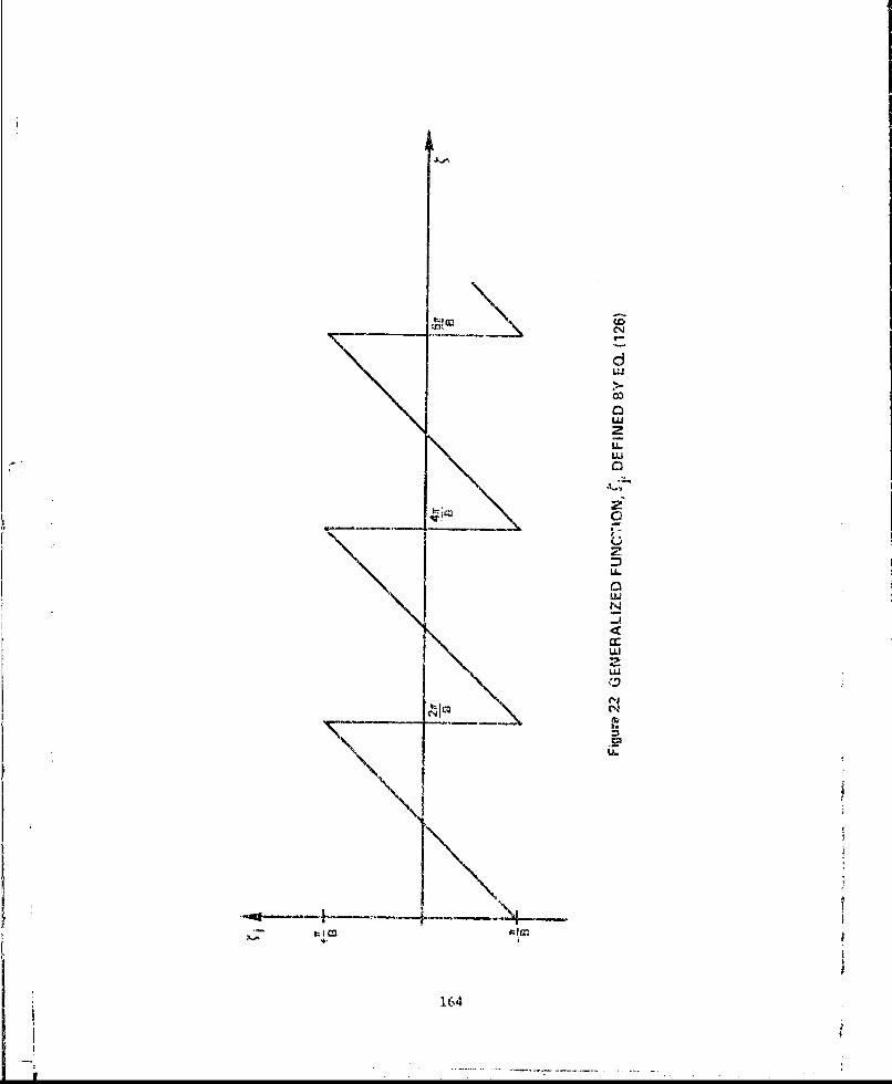
22 Generalized Function, - ., Defined By Eq. (126) .......... 164
x
TABLES
TABLE TITLE PAGE
1 Comparative Influence of Various Wake Profiles on AcousticPredictions .............. ......................... ... 42
2 Comparison of Modal Amplitudes Computed by Clark et al. 19
with Present Theory ................ ..................... 44
3 Coefficients in the Expression for the Normal VelocityComponent of a Lifting Rotor, Equation (172) ........... .... 101
xi
SYMBOLS
Separate li:•ts of symbols are given for Sections IlI and IV.
SYMBOLS FOP SECTION III, APPROXINtATE MODEL OF ROTOR-STATOR INTERACTION NOISE
0-o undisturbed sound speed
A?, Glauert coefficients, Appendix B
/,• admittance of nrin mode, Equation (27)
B number of rotor blades
h axial separation of blade row centerlines
C dcCf semi-chord pengath)
C l drag coefficient per unit span, Equation (37)
CL lift coefficient per unit span, Equation (43)
• r total pressure loss coefficient
ds blade spacing
FR,F, force per unit volume exerted by blades on the air
4 hub/tip ratio, r, ,/ri
4 acoustic wave number, iN 8di/aI.o
A Equation (18)
xii
SYMBOLS, SECTION III (Cont'd.)
LRL total unsteady lift per unit span
unsteady load harmonic index
"in radial mode index
M*' axial flow Mach number
N; harmonic of blade passage frequency
n azimuthal mode index
pressure perturbation.
Fourier decomposition of pressure field, Equation (6)
n • pressure modal amplitude, Equation (18)
P° LL total sound power radiated along the duct, Equation (28)
",' sound power in (n,m) mode
dynamic pressure
Rn(vradi.,- eigenfunctions, Appendix A
r cylindrical radius
rr hub, tip radii
xiii
SYMBOLS, SECTION III (Cont'd.)
S acoustic source distribution, Equation (4)
S',, Fou'rier decomposition of source distribution, Equation (7)
SPL sound pressure level, Equation (23)
t time
U• uniform axial velocity
U tangential velocity, -ar
U axial velocity perturbation, or viscous wake velocity defect
uL L., axial velocity mode amplitude, EquatiQn (27)
V, mean velocity relative to blade row
-v, radial eigenvalue for (n,rn ) mode, Appendix A
X axial coordinate
Sx5 axial location of rows in line dipole model
X.,Y2 ZL magnitudes of ith harmonic of unsteady lift per unit span resulting
from the three interaction mechanisms, Equation (11)
y viscous wake half-width
0,S blade row stagger angles
xiv
SYMBOLS, SECTION III (Cont'd.)
(l-M1)l/2
(5(x) Dirac delta function
2 Fourier transform variable in axial coordinate
0 azimuthal coordinate
n I, 1 / r.
•)g fundamental blade loading frequency• Equation (12)
p. undisturbed density
6" dimensionless radius, r/•r
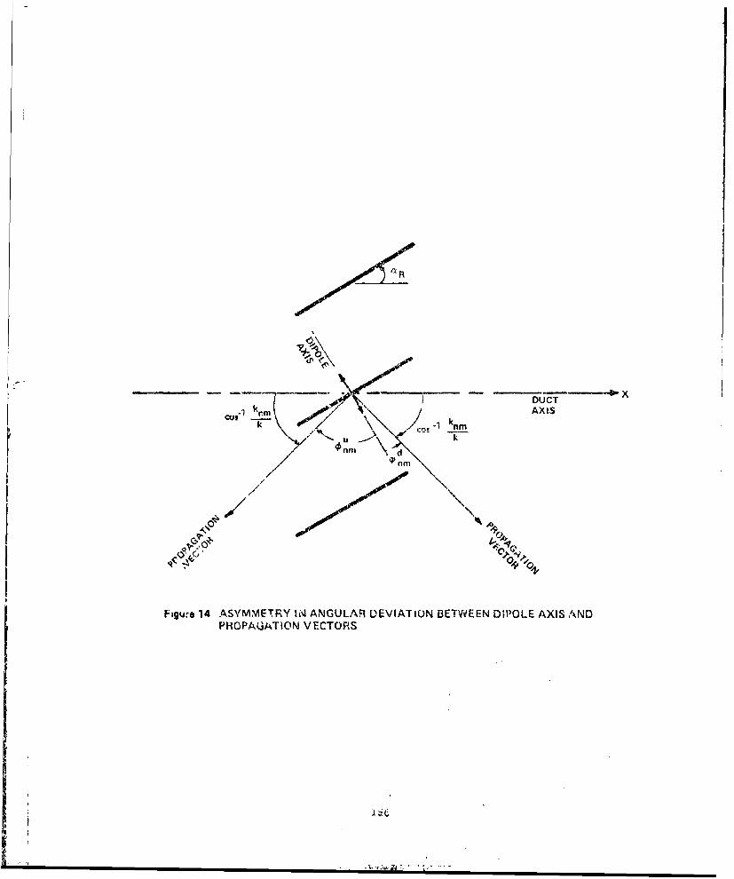
L&, t0" propagation angle of (nrvn ) mode, relative to dipole axis, Figure 14
f. rotor angular velocity, radians/sec.
w acoustic frequency, Nf 8.a.
< ) denotes time average over one blade-passing period
magnitude of a vector or complex number
X complex conjugate
xv
SYMBOLS, SECTION III (Cont'd.)
Subscripts
1,2 refer to upstream or downstream blade row, respectively
C evaluated on viscous wake centerline
referes to I th loading harmonic
ryl refers to m th radial mode
i refers to v, th azimuthal mode
R,5 refers to rotor or stator blade rows, respectively
Superzcripts
L,d refer to upstream or downstream propagating waves, respectively
SYMBOLS FOR SECTION IV, DIRECT LIFTING SURFACE THEORY FOR A COMPRESSOR ROTOR
a, undisturbed sound speed
R vector defined in Equation (63)
Ph coefficient in polynomial expansioin, for axial variation of blade loading
P,6. real part of coefficient defined in Equation (173), see Table 3
xvi
SYMBOLS, SECTION IV (Cont'd.)
5 number of blades
6,6. imaginary part of coefficient defined in Equation (173), see Table 3
C blade chord
C axial projection of blade chord
CL)CB• coefficient defined in Equation (173), see Table 3
df~,d, integrals defined in Equation (C-50), Appendix C.
D dipole strength
D,8* quantity defined in Equation (167)
r) e, 6 unit vectors in cylindrical coordinate system
f function of radius appearing in blade thickness distribution,Equation (110)
F force per unit volume
Snet force on control volume
axial dependence of blade thickness distribution, Equation (110)
G Green's function
U),6 quantity defined in Equation (178)
xvii
SYMBOLS, SECTION IV (Cont'd.)
ratio hub radius to tip radius
H( ) Heaviside step function
I,12 surface integrals in Equation (66)
1(z) integral of pressure perturbation along streamlines
• integrals defined in Appendix C
A radial mode number
K, 4 radial eigenvalues
L operator defined by Equation (58)
Lmsk quantity defined in Equation (173)
multiple of blade nuxnber for azimuthal mode, / = 8
mass flux to first order in perturbation quantities
M Mach number of undisturbed axial stream, U/Ca.
MR Mach number based on undisturbed relative velocity in blade fixedcoordinates, U 6/L.
MT Mach number based on rotor speed at blade tip radius, wrT/ a,
n- azimuthal mode number or coordinate mutually normal to undisturbedstreamline and radial directions
xviii
SYMBOLS, SECTION IV (Cont'd.)
unit vector normal to undisturbed streamline and radial directions
17c blade camber line
1)7,L. distance to upper and lower blade surfaces
- pressure perturbation
undisturbed pressure
terms in expression for pressure perturbation, Equation (148)
A-P local blade loading
Ajp blade loading averaged over radius
Pi terms in polynomial representation of blade loading, Equation (190)
0. source strength
,z integrals defined by Equation (C-39), Appendix C
r radial coordinate
Rnk normalized radial eigenfunctions
5 distance along undisturbed streamlines
5 unit vector along undisturbed streamlines
i.5
xix
SYMBOLS, SECTION IV (Cont'd.)
4t ) +1 for arg > 0, -1 for arg < 0
S surface area
S(4) function defined in Equation (121)
t blade thickness
Thgk quantity defined in Equation (131)
axial component of torque exerted on control volume
U undisturbed axial velocity
UR undisturbed relative velocity in blade-fixed coordinates
Sperturbation velocity, (2r, ir , zf,) or (Vr, rn ,Vs'
(17,) terms in normal component of perturbation velocity, Equations (160)and (168)
V volume
V?88 quantity defined in Equation (117)
VI total velocity in blade fixed coordinates
Z normalized axial coordinate, Equation (179)
2 axial coordinate
xx
SYMBOLS, SECTION IV (Cont'd.)
local vortex strength
F blade circulation
6( ) Dirac delta function
4,-- Kronecker delta
vanishly small quantity
helical coordinate, • = - wZ/U
•" generalized function defined in Equation (126)
q ca / 2 rr
8 azimuthal coordinate
\.k quantity defined in Equation (71)
-. ,08 quantity defined in Equation (114)
Sindex of Lommel function
3 normal to surface
4 Fourier transform variable, or dummy variable for argument of Besselfunctions
xxi
SYMBOLS, SECTION IV (Cont'd.)
• poles of integrand in Equation (78)
/o density perturbation
undisturbed density
a- normalized radial coordinate, r/ rr
velocity potential
4 coefficient in expansion of I in terms of duct eigenfunctions,Equalion (72)
scalor function defined in Equation (62)
t. w,-,/L
ta-riliJr/U)
wo angular velocity of rotor
-- Fourier transform
C ) dimensionless variable, see Equation (186)
Subscripts
D property of dipole solution
H evaluated at hub radius
xxii
SYMBOLS, SLC'T[ON IV (Cont'd.)
4 th blade
A th radial mode
n ,L th azimuthal mode
0 source coordinates
S property of source solution
7 evaluated at tip radius
xx-iii
SECTION I
I NTRODUCT ION
The useful operating range of a turbine engine compressor is greatly
influenced by its stalling characteristics. The optimum performance of a
turbo-propulsion system is usually achieved when the compressor is operating
near its maximum pressure ratio, However, this optimum is generally not
attainable because it occurs close to compressor stall a.id unstable flow con-
ditions. Because of the serious mechanical damage that may result during com-
pressor stall cycles, a factor of safety (stall margin) must be provided
between the compressor operating line and the stall boundary. This is usually
done by prescheduling the primary engine controls. However, the prescheduling
approach can lead to the requirement for a large stall margin in order to keep
the engine from stalling under all possible transient and steady state flight
conditions. It is clear, then, that an engine control system that can sense
incipient destructive unsteady flow in a compressor and take corrective action
would allow for reduced stall margins in the design and thus lead to large
engine performance and/or efficiency gains. Recognition of this fact has been
the motivation for a continuing program of research that the AFAPL has sponsored
at Calspan dating back to 1962.
The work at Caispan has been both theoretical and experimental in
nature and has been aimed at obtaining a sufficient understanding of the rotat-
ing stall phenomena such that its onset and its properties can be predicted
and controlled. The capability of predirting the onset of rotating stall on
isolated blade rows of high hub to tip ratios in low speed flows was demon-
strated in Reference 1. In addition, the basic feasibility of developing a
rotating stall control system was demonstrated in the Calspan/Air Force Annular
Cascade Facility. This present report sunmnarizes the latest three year
research program at Calspan. The specific goals of the present program were
to extend the fundamental studies of rotating stall to consider the effects ofcompressibility, blade row interaction and inlet distortion; and to extend the
m l l m l m l m mI
fundamental aerodymamic and acoustic analysis of flow through a compressor.
In addition, the rotating stall control system was validated by successful
ground tests on a J-85-5 turbojet engine.
The work is reported in three separate volumes. Volume I entitled,
"Basic Studies of Rotating Stall", covers the theoretical and experimental
work on the effects of distortion and close coupling of blade rows on rotating
stall inception and properties. In addition, the theoretical analysis of com-
pressibility is treated in the two-dimensional approximation and the initial
development of a three-dimensional theory is given. Volume II entitled, "In-
vestigation of Rotor-Stator Interaction Noise and Lifting Surface Theory for
a Rotor", describes the development of a linearized lifting surface theory for
the subsonic compressible flow through an isolated rotor row. In addition, a
theoretical and experimental study of the noise generated by the interaction
of a rotor and stator is described. Volume III entitled, "Development of a
Rotating Stall Control System", describes the development and testing of the
control system installed on a low speed research compressor and on a J-85-5
turbojet engine.
In the current three-year segment of the ongoing research program on
rotating stall, the scope of the investigation was expanded to include studies
of the aerodynamics and acoustics of axial flow compressors. Volume II con-
tains the results of this aspect of the program, which consisted of two basic
parts: the theoretical and experimental investigation of discrete-tone noise
generation by the interaction of a rotor and stator, and the development of
the three-dimensional direct lifting surface theory for a compressor rotor.
An approximate model has been developed to predict the sound pressure level
and total power radiated at harmonics of the blade passage frequency for a
rotor-stator stage. Also, measurements were made of the sound pressure levels
produced on the outer duct wall of the annular cascade facility by a rotor-
stator pair. In the development of a direct lifting surface theory, the
governing integral equation relating the rotor blade loading to prescribed
incidence and camber lines has been formulated and progress made toward its
numerical solution. The experimental and theoretical studies of rotor-stator
interaction noise are reported in Sections II and III, respectively. The
direct lifting surface analysis is presented in Section IV.
2
SECTION II
EXPERIMENTAL ACOUSTICS RESEARCH
As a part of the work under a previous program, Contract AF 33(615)-3357,
an annular cascade facility was designed and fabricated. Its principal purpose
is to provide fundamental experimental data during and prior to the occurrence
of rotating stall in order to improve our understanding of the phenomena and
for use as a guide in improving the theoretical analysis. In addition to the
study of rotating stall, the facility has also been used to provide acoustic
data for comparison with theory and to evaluate the operation of a prototype
rotating stall control system. The fundamental experiments on rotating stall
are described in Volume I of this report and the control system tests are
described in Volume III. This section of Volume II presents the results of
the acoustic experiments.
Two sets of experiments were performed in support of the theoretical
developments described in Section III and IV of this volume. The first set of
experiments were designed to provide data for correlation with the approximate
theory of Section III for the prediction of rotor-stator interaction noise.
In these experiments, the far-field sound pressure levels generated by roto-
stator interaction were measured in the constant area annulus upstream of a
rotor-stator stage. These measurements were performed over a range of rotor
speeds for two different stagger angle settings of the stator blades. The
second set of experiments were intended to provide a measure of the tip pressure
loading on an isolated rotor for comparison with the direct lifting surface
theory of Section IV. In these experiments, time-varying records of the outer
wall static pressure fluctuations caused by blade tip passage were obtained
for a number of different chordwise locations on the rotor blades. The scope
.of these tip loading experiments was very limited.
The order of presentation of the experimental studies in the remainder
of this section is as follows. A brief description of the annular cascade
facility is presented in Section II-A. Section II-B presents the results of
3
the measurements of noise caused by rotor-stator interaction. This is followed
by the presentation, in Section II-C, of a typical set of results obtained for
the blade passage fluctuations on an isolated rotor. Finally, some concluding
remarks on the experimental studies are presented in Section II-D.
A. DESCRIPTION OF ANNULAR CASCADE FACILITY
A detailed description of the annular cascade facility has been pre-
sented in Reference 1, and further details are given in Volume I of this
report. Only a brief description of the facility is given here.
The annular cascade facility consists of a test section built around
the outer front casing of a J-79 jet-engine compressor with a Calspan fabri-
cated hub. The facility includes a bell-mouth inlet on the outer casing and a
bullet nose on the hub to provide a smooth flow of air to the test section.
Outlet ducting is connected to an independently variable source of suction to
provide the required flow through the annulus. An electrically powered two-
speed axial flow fan is used as the source of suction. Continuous control of
the mass flow is achieved through the use of variable inlet guide vanes to the
fan and a variable damper in the fan exit flow.
The test section of the annular cascade forms a circular annulus with
an outer diameter of 29.35 inches and an inner diameter of 23.35 inches which
provides a hub-to-tip ratio of 0.80. The outer casing will accept up to six
variable stagger angle stator rows. The hub has provision for two rotor rows
at the third- and fifth-stage rotor locations of the J-79 compressor. At the
time the acoustic studies were performed, either rotor row could be rotated
while the other was held fixed or both rows could be rotated together. The
rotor assembly was powered by a 24 horsepower hydraulic motor. Rotational
speed was continuously variable in either direction between zero and approxi-
mately 1500 rpm. An external hydraulic pump system powered by a 30 horsepower
electric motor was used to provide power for the hydraulic motor.
4
Although the speed range of the rotor was restricted at the time of
these tests, it was possible to perform acoustic tests for comparison with the
theory of Section III, The flexibility of control and the relative absence of
background noise in the facility are features which were highly useful in the
performance of the tests.
B. NOISE GENERATED BY ROTOR-STATOR INTERACTION
The configuration of the annular cascade used for the rotor-stator
interaction studies is shown in Figure 1 along with some details of the micro-
phone-probe assembly used in the acoustic work. The rotor-stator stage
studied is designated Rotor Set No. 1 (46 blades) and Stator Set No. 1 (54
vanes) in Reference 1. These are modified blade rows from the fifth stage of
a J-79 compressor. Their characteristics and performance when used as iso-
lated blade rows in the annular cascade have been presented in Reference 1.
The mean stagger angles (at mid-annulus) were R = 400, Ms = 37.20 or 28.20,
and the semi-chords C, = .0604 ft. and C. = .054 ft. The axial separation
of the iid-chord planes was b = .125 ft.
The sound pressure levels produced by rotor-stator interaction were
measured on the outer casing upstream of the rotor. In taking these data, the
fan system downstream of the annular cascade was turned off and the fan was
allowed to rotate freely under the influence of the flow generated by the
rotor in the annular cascade. In addition, all dampers in the downstream
drive system were opened wide. It was convenient to use this wide open con-
figuration because it was found to provide nearly constant inlet swirl angles
relative to the rotor. That is, the.mean axial velocity in the annular
cascade increased in direct proportion to the rotor angular velocity. This
feature made application of the rotor-stator interaction theory much simpler
because the dimensionless steady state loss and turning performance data for
the rotor also remained approximately constant with changing rotor speeds.
A Bruel and Kjaer (B & K) acoustic-probe with its tip flush with the
inner surface of the compressor casing was used in combination with a B & K
condenser microphone and sound level meter to measure the interaction noise.
The sound level meter output was recorded on an instrumentation quality FM
tape recorder. The recorded data were processed later on a modified General
Radio Type 1921 real time analyzer to obtain one-third octave spectra of the
signals.
The tape recording of the noise was necessary because the rotor-stator
interaction harmonic frequencies were above the frequency range available on
the real time analyzer. The maximum frequency accommodated by the spectrum
analyzer is the third octave centered on 2500 Hz while the noise harmonics
extended up to approximately 5000 Hz. The effective frequency range of the
noise spectrum was reduced by a factor of four bqv recording at 30 ips and playing
back for spectrum analysis at 7-1/2 ips. Absolute calibration of the complete
system including the tape recorder was obtained by recording a 114 db signal
from a General Radio microphone calibrator at the beginning and end of each
tape. These calibration signals were used to set the gain of the overall
system when played back through the spectrum analyzer.
Within the frequency range of interest, the response of the microphone-
sound level meter system was essentially flat. However, the acoustic probe
assembly introduced frequency dependent distortion to this flat response.
Thus, it was necessary to obtain a calibration for the complete system in-
cluding the acoustic probe. A sketch of the acoustic probe calibration
apparatus is shown in Figure 2. All of the apparatus shown in the sketch is
manufactured by B & K. The calibrator consists of a small cavity into which
sound is introduced by an earphone speaker. For a given excitation of the
speaker, the sound pressure level in the cavity is measured by the microphone
in its reference level location (position #1). The acoustic probe is in
place during these measurements with a dummy microphone inserted in its end.
Following the reference level measurements, the microphone is inserted in the
acoustic probe (position #2) and the dummy microphone inserted in the reference
6
level lucation (position #1) . The sound pressure levels detected by the micro-
phone in the probe are then determined for the same speaker excitation as used
in the reference level measurements. The difference between the two sets of
measurements provides a frequency dependent calibration for the probe.
In the current work, the probe was calibrfted first without any steel
wool damping material in the tube. This calibration showed a rather large
(12 db) probe resonant peak at approximately 1900 Hz. The probe was then
calibrated with three different degrees of steel wool damping and a final
damping configuration was selected for use in the noise measurements. The
sound pressurc levels measured with pure tone excitation of the earphone
speaker are shown in Figure 3 for the frequency range of interest and for both
microphone positions in the calibrator. Both curves drop off at high frequency
because of frequency response limitations on the earphone speaker. The dif-
ference between the two curves provides the calibration of the acoustic probe.
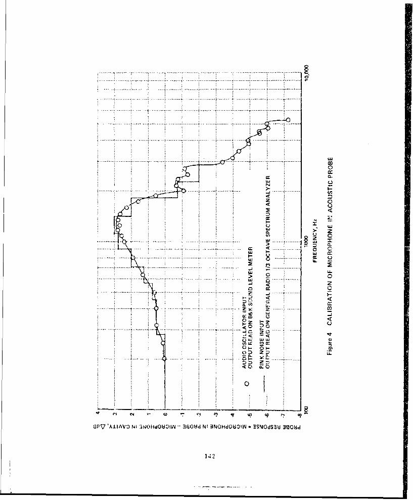
]he probe calibration is shown in Figure 4. The circular points were
obtained %ith pure tone excitation of the speaker at the indicated frequencies.
These values must be subtracted from the measured noise levels. A second
calibration result is also shown on this figure as solid straight line segments.
This wa., obtained by exciting the speaker with pink noise and analyzing the
result on the 1/3 octave real t.in.e analyzer. The effective 1/3 octave band-
widths of the results arc represented by the length of the horizontal portions
of the segmented curve. If allowance is made for the larger bandwidth of the
1/3 octave analyzer, the agreemnent bQtween the two calibration curves is very
good. Since the rotor-stator interference noise was very close to a pure tone,
the pure tone calibration curve was used in correcting the measured results.
The pure tone nature of the interference noise is illustrated in
Figure S. This figure shows photographic oscilloscope records of the unfiltered
output from the sound level meter. In the upper photograph, the top trace is
generated by the noise signal and the lower trace is the output from an audio
oscillator tuned to the same frequency' as the predominant noise harmonic.
7
The jitter in the upper trace signals is caused by the presence of frequencies
other than the predominant harmonic. Tuning of the audio oscillator was
accomplished by setting the oscillos,ope trigger mechanism to fire on the
audio oscillator signal and then adjusting the oscillator frequency until a
stationary noise signal was attained, This procedure led to a number of
possible oscillator frequencies for the noise harmonic. The correct frequency
was difficult to determine because of the jitter in the noise signal. The
oscillator frequency was then deternined by forming a Lissajous figure from
the noise and oscillator signals. The lower photograph in Figure 5 shows the
Lissajous figure corresponding to the upper photograph. The multiple ellipses
in the lower photograph show that the noise and oscillator signals are cor-
rectly matched in fundamental frequency. The multiplicity of ellipses arises
from the same reason as the jitter in the upper photograph.
The procedure described in the previous paragraph was used to determine
the frequency of the predominant pure tone noise for all tests where a strong
blade row interaction signal was obtained. Thus, it was possible to identify
accurately Ahich harmonic of rotor blade passage frequency was being excited
by the interaction mechanism.
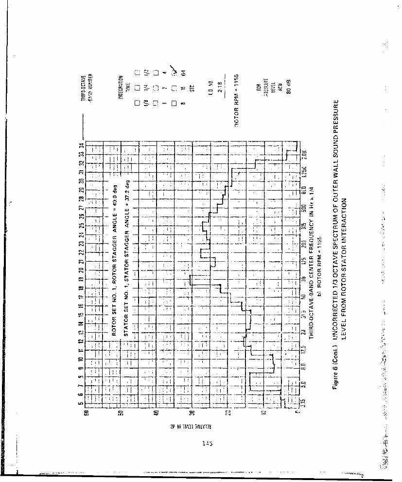
Samples of the one-third octave spectra of the interaction noise are
shown in Figures (,a through 6d. TIesc figures are direct reproductions of the
output from the spectrum analyzer. Absolute sound pressure level for any
one-third octave band is obtained by correcting the relative db levels for
system gain and for acoustic probe response. The frequency dependent probe
response correction has been discussed previously. The system gain corr"ection
is indupendent of frequency and is noted on the lower right hand side of each
figure. For the particular examples of Figure 6, system gain is corrected for
by adding 80 db to all relative levels.
Figures 6a through 6d have been chosen to illustrate the extremely
sharp rise in interaction noise as rotor speed is increased over a very small
range of rpm from below cutoff to above cutoff of the fourth rotor blade
passage harmonic. ligures 6a and 6b correspond to conditions slightly below
,utoff. Here the noise spectra are generated primarily by turbulent pressure
fluctuations within the boundary layer en the outer wall and by the free.
wheeling fan downstream of the annular cascade test section. Figures 6c and
6d show the sharp rise in fourth harmonic interaction noise as the rotor rpm
increased to above cutoff conditions. This rise can be seen in the third
oLtave bands cen.tered at 11z x 1/4 = 800 and 1000. both of these third octave
bands respond because the pure tone frequency is nearly mid-way between these
two bands. The measured pure tone frequency is shown on the lower right hand
side of Figures 6c and 6d. It can be seen that the pure tone frequency is
approximately 3600 Htz for both figures corresponding to Hz X 1/4 = 900.
'The correct sound pressure level for the pure tone signal was obtained
from spectra such as shown in Figure 6 by combining the two third octave band
responses closest to the pure tone frequency and then correcting the indicated
SPL for acoustic probe response at the measured pure tone frequency. An
example of the procedure for the data of Figure 6d is as follows.
Relative Level for third octave centered at Hz x 1/4 = 800 is 34.75 db
Relative Level for third octave centered at Hz x 1/4 = 1000 is 39.25 db
Combined Level Corrected for system gain ý 43.3 + 80 = 123.3 db
Probe response at pure tone frequency (3610 Hz) = -4.7 db (from Figure 4)
Corrected pure tone Sound Pressure Level = 123.3 - (-4.7) := 128.0 db.
The pure tone frequency in all cases where it was measurable corres-
ponded very closely to either the calculated fourth or fifth harmonic of rotor
blade passage frequency. For the example given above, the calculated fourth
harmonic of rotor blade passzngc frequency is 3588 Hz and the measured pure tone
frequency is 3610 l1z. The difference between the two is within the accuracy
of the audio oscillator used in the measurements. For conditions below cutoff
such as shown in Figures 5a and 6b, the sound pressure levels for the fourth
blade passage harmonic were estimated from the data uý,ing the calculated fourth
harmonic frequency and the measured levels in the two third octave bands closest
to this calculated frequency.
9
t .lnA.:.A°;r*O.- - t ~ t ~ - fflI aft.. nt
ii
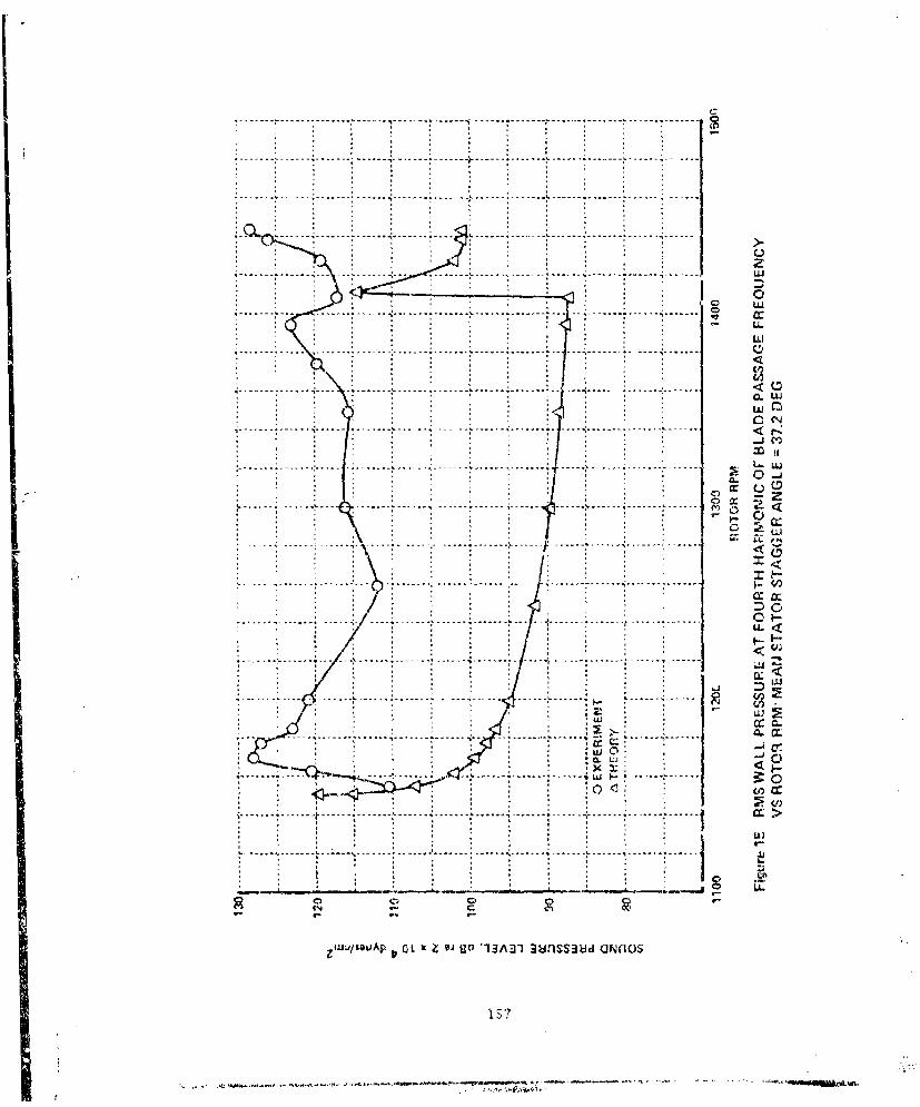
The results of the interaction noise measurements are summarized in
Figures 7 and 8 for rotor speeds ranging from below cutoff to the maximum
speed available. Figure 7 shows the results obtained for a stator stagger
angle of 37.2 degrees and Figure 8 show, the results obtaind for 28.2 degrees.
In both figures, an estimate of the background level in the third octave band
closest to the measured pure tone frequency is also shown. This was obtained
by inspection of the third octave bands on each siae of the band:; used to
calculate the pure tone levels and must be considered highly approximate in
nature. Any data point for harmonic level of the SPL within about 10 db of
the approximate background level probably contains a certain degree of back-
ground noise from the mechanical systems or the turbulent wall pressure
fluctuations. The closer the data point is to the approximate background
level, the larger the contribution will be,
Most of the data shown in Figures 7 and 8 correspond to the fourth
harmonic of rotor blade passage frequency. The fifth harmonic was generally
masked by the backgruund lve .uu Could not ukUtCLt ., [IUWCVtX, for
a stator stagger angle of 28.2 degrees, the fifth harmonic was detectable at
moderately low rotor speeds, where the background noise level was low but the
rotor speed was high enough to allow propagation of this mode in the annular
duct system. The results are shown on the left side of Figure 8,
It was not possible to obtain interaction noise signals at harmionics
of blade passage frequencies below the fourth harmonic. The generation of
lower harmonics would require either a greater rotor speed capability or else
blade configurations that are not available to the annular cascade in its
present configuration. It is unfortunate that the generation of lower har-
monics was not possible because the prediction of harmonics as high as the
fourth presents a test for the interaction theory which may be more severe
than is warranted in the present state of the theoretical development. Never-
theless, these data have been used for comparison with the theoretical pre-
dictions in Section 11, and are discussed more fully there.
10
"I' • +
C. ISOLATED ROTOR MEASURFMENTS
In addition to the rotor-stator interaction noise experiments described
above, measurements were made of the fluctuati.ng wall pressures produced by an
isolated rotor. These measurements, which were intended to provide information
on the blade tip loading, were taken at six chordwise locations along the
outer casing wall.
The configuration of the annular cascade was simi lar to that shown in
Figure 1 but with the stator row removed. Rotor Set No. I was used with the
blade stagger angle set at 40 degrees at mid-annulus (48 degrees at the tip).
As noted earlier, this rotor set had been studied previously to determine its
steady state turning and loss performance (Reference 1).
Pressure fluctuations produced by the passage of the blades wele
obtained at rotor speeds of 600, 700, 800, 900 and 1000 rpm, while the mean
axial velocity through the test section was held at 60 ft/sec. At the lowest
rotor speed, the rotor blades were very lightly loaded, while at the highest
speed the loading was large enough to induce rotating stall.
The pressure signals were measured by' a Setra Systems Model 242 TC
pressure transducer closely coupled to a hole in the outer casing of the annular
cascade. The time-varying pressure signals were recorded photographically f'orom
a dual trace oscilloscope. A second signal was used to indicate rotor blade
position. This signal was generated by a magnetic pickup which sensed blade
tip passage past a point or. the outer casing of the annular cascade. Instanl-
taneous blade post.tions with respect to the pressure signals were calculated
from the magnetic pickup signals and the geometric relationship between the
magnetic pickup and the pressure tap.
The six ayia1 stations used for the wall pressure measurements were
situated at 13, 18, 32, 49, 64 and 79 percent of the rotor chord. A set of
results is shown in Figure 9 for the station at 18 percent of the chord.
-11.-
These results are typical of the measurements at all six cliordwise measuring
stations. Parts (a) through (d) of Figure 9 show the records obtained at
rotor speeds between 600 and 900 rpm. The relative inlet swirl angle at the
rotor tip is indicaýed for each rotor speed. The instantaneous locations of
the blade pressure and suction surfaces with respect to the pressure signals
are shown also.
As expected, the maximum amplitude of the pressure fluctuations in-
creases with increasing rotor speed. (Note that the scale for pressure
signals varies for different rotor speeds. The scale in each case is indi-
cated to the left of the pressure signals.) Hlowever, the shapes of the
fluctuating pressure signals are unexpected. The data records show that the
maximum wall pressure is reached well ahead of the blade pressure surface at
all rotor speeds. Moreover, a double pressure peak occurs at the lower rotor
speeds, one ahead of the rotor pressure surface and one approximately at the
location of the pressure surface, The peak in pressure at the rotor pressure
u,,rr hraii to disa.-ppe ba r-r O is T increased. The reason for the
unexpected shape of the pressure signals is not definitely known. However,
it is speculated that the results may be caused by three-dimensional effects
associated with the relatively large clearances between the rotor blades and
the outer casing. As explained in Volume I, a blade tip clearance of approxi-
mately 0.05 inches was required to compensate for thr slightly oval shape of
the production J-79 casing which forms the outer wall of the annular cascade.
The fluctuating wall pressures recorded during rotating stall are
shown in Figure 10 for all six chordwise locations. Although the rotating
stall phenomenon is beyond the scope of the direct lifting surface theory,
these data are presented as being of general interest to the overall program;
pressure signals such as the ones shown in Figure 10 are used as stall do-
tectors in the rotating stall control system which is described in Volume III
of this report.
12
The rotor speed for the records in P igure 10 was 1000 rpm and tile mean
axial velocity was 60 ft/sec. The oscilloscope sweep speed in Figure 10 is
mLuch slower than in Figure 9 so that the blade passage pressure peaks are
highly compressed. The interest here is centered on the pressure fluctuations
during passage of a rotating stall cell. Each photograph in Figure 10 shows
the passage of two stall cells, The phase relationships between the separate
photographs have no meaning since the records vere not obtained simultaneously.
Figure 10 illustrates that the character of the stall cell passage
signals change considerably with chordwise location on the rotor. Near the
leading edge, the stall passage signals coincide with an amplitude reduction
in the blade passage signals. In this region the combined maximum amplitude
of the pressure signals during stall passage is almost the same as the blade
passage pressure amplitude between stall cells, In contrast, near the trailing
edge the passage of a stall cell coincides with an increase in amplitude of'
the blade passage signals and the ccmbined maximaum amplitude is larger thanm
the blade passage ampli.tude between stall cells.
The rotating stall control system detects unusually large peak
amplitudes in pressure signals such as shown in Figure 10. Control action is
taken when these peak amplitudes reach a prVahtermir.eC ro'rc-cs value. It
is required that only those fluctuating pressure levels associated with rota-
ting stall should initial control action. Tests of the control have shown
that the best performance is obtained when pressure signals, due to blade
passage, are removed by low-pass filters. It is clear from Figure 10 that
elimination of the blade passage signals will greatly improve the signal to
noise ratio for stall detection purposes. This is true even for the pressure
tap locations near the blade trailing edge since the blade passage pressure
fluctuations still have an appreciable amplitude between the stall cells.
D. CONCLUIDING REMARKS
The rosults of two separate experimental investigations have been
presented in Section II. In the first investigation, Section Il-B, the
13
far-field noise generated by rotor-stator interaction was measured to provide
data for correlation with the approximate theory prescted in Section 1J I.
In the second study, Section II-C, the fluctuating outer-wall static pressures
generated by passage of the blade tips of an isolated rotor were measured to
provide data for comparison .th the direct lifting surface theory of Section IV.
The rotor-stator interference noise studies presented in Section 1I-B
consisted of measuring the sound pressure levels in the conrstant area annulus
far upstream of a rotor-stator stage, The measurements were made at a series
of rotor speeds for two stagger arngle settings of the stators. The results
contained detectable pure tone components only at the fourth and fifth har-
monics of blade passage frequency. The generation of lower harmonics was not
possible because the rotor speed capability was limited at the time of the
tests. Since the performance of these tests, the rotor speed capability of
the test rig has been increases. It is olanned to use this capability to
perform additional measurements for conditions in which lower harmonics of
blade passage frequency are propagating, The results of the current tests
are compared with theoretical predictions in Section Ill.
The isojated rotor studies of Section Il-C were intended to provide
a measure of the blade tip pressure loading for comparison with the predictions
of the direct lifting surface theory of Section IV. However, the theoretical
development had not reached the stage where quantitative predictions could
be made. Thus, samples of some of the data are presented as of interest in
themselves. Inspection of the results suggest the measured pressures may
have been influenced by rotor tip clearance effects, As such, the results
may not be predictable by the direct lifting surface theory, Nevertheless, a
comparison between theory and experiment would still be of interest.
14
SECTION III
APPROXIMATE MODEL OF ROTOR-STATOR INTERACTION NOISE
The interactions betw;een rotor and stator blade rows have lonig been
recognized as a major source of noise in subsonic axial flow fans and com-
pressors. The interactions consist of fluctuating forces which arise because
of the motion of the blade rows relative to one another, and in turn, act as
acoustic sources. Out of practical necessity, little detailed attention can be
paid to the interaction noise at the design stage, where each row is usualJy
modeled as an isolated two-dimensicnal cascade in a steady tLtrlisturbed flow.
Interactions can be kept to a minimum by spacing the rows several chord
lengths apart, but the designer is generally working under size and weight
constraints as well. This portion of the report presents the results to date
of a combined theoretical and experimental program aimcd at a better under-
5tanding of rotor-stator noise generation, and methods for its "allevia'tion
May investigations have appeared in the literature which treat, both
the aerodynamic and/or acoustic aspects of the problem, e.g. , References 2-26,
which is by no means an all-inclusive list. Because of the complexity of the
problem, the various theoretical models represent several combination5 of
simplifying assumpttons needed to make them amenable to analysis. These include
the use of free-field vs. ducted boundary conditions, tw-o-dimensional vs. axi-
symmetric blade rows, and variou0 degrees of approximation to the unsteady aero-
dynamic processes. Probably the most uni-versal approximation, and the most
restrictive, has been the use of incompressible flow theory to estim•ate the
fluctuating blade loads. Strictly speaking, this restricts the range of
validity of these models to very low flow speeds.
As the speeds of modern turbomachitiery are definitely subsonic, and
often transonic, the need to include compressibility effects is obv.oua. The
goal of the present theoretical work is to ii corporate a compressible flow
aerodynamic model into the prediction of rotor/szator interactioni noise.
Published investigations, which allow for compressibility effects in the pre-
diction of unsteady aerodynamic loads, include those by Kaji and Okazaki, 22324 26
Mani, Osborne, Whitehead25 and Flceter.6
15
Kaji and Okazaki treat the ncar-field aerodyvnamic and far-fiAld
&-ousti.: regions of the flow in a en tfied lineari :ed tcictmenlit. Thei r ail I ys is
is the most complete because it includes the upwash velocities on each blade
generated not ornly by the forces on that same blade, but also by the forces
(both steady and unsteady) on all the other blades in that same row, as well
as those from blades in the neighboring row. Unfortunately, this requires one
to solve simultaneously for the loading distribution on both rows using a pair
of coupled singular integral equations. Manil23 simplified the problem some-
what by neglecting the influence of the unsteady loading on the neighboring
row. It is still necessary to solve a Pair of integral equations to obtain the
unsteady loading on both rows, but the two are no longer coupled. Similarly,
the aerodynaimlic analyses in References 2S and 26 require the numerical solution
of an integral equation for the loading on each row. These analyses are all
based on two-dimensional cascade models.
It is ultimately hoped that our work on the three-dimensional lifting
surface theory for annular blade rows can be applied to the rotor-stator
interaction problem. This would amount to the extension of the Kaji and
Okazaki analysis to include three-dimensional effects, and is expected to lead
again to a pair of coupled integrAl equations, probably even more complex than
theirs. Hence, it is likely that more experience with the problems of stealy
and unsteady flow through an isolated rotor (reported on in Section IV, below)
would be needed before applying such an analysis to rotor-stator interaction,1.
In the interim, however, it was felt that our understanding of the basic
mechanisms could benefit greatly from the application of a simpler mcdel, and
the corapari son of its theoretical predictions against the acoustic data taken
in the annular cascade (see Section II)
The theory developed under the current prugran avoids the necessity
of solving integral equations, and thus considerably reduces the complexity of
the analysis, as well a>, computing times. In this simplified model, the aero-
dynamic and acoustic problems are treat.ed individually and then matched together.
The aerodynamic analysis is that published by Osborne,24,27 which essentially,
reprcsents the compressible extension of the now classic analysis by Kemp and
16
Sears.'3 Osborne's results are closed form expressions for the unsteady
blade loads on both rotor and stator which are easily accommodated in the
acoustics calculation, since no numerical techniques are required. The
principal features of this model are described in Section 111-B below.
The Osborne aerodynamic analysis models each row as a two-dimensional
cascade, which is strictly justifiable only at large hub/tip ratios; even then,
McCune28 has shown that in certain types of transonic flow, no logical two-
dimensional cascade limit exists. The acoustic analysis described in Section III-A
below employs axisymmetric annular blide rows housed in an infinite hard-walled
cylindrical duct with a uniform axial flow. Accordingly, Osborne's expressions
for the fluctuating loads are applied on a strip theory basis at each radial
station. This procedure was followed so that in the event a truly three-
dimensional aerodynamic analysis becomes available, it can more easily be in-
corporated in the model.
The combined aero-acoustic analysis in Section III-C results in easily
evaluated expressions for the sound field in terms of the same duct modes
studied previously by Tyler and Sofrin and Morfey.5,6 A computer program has
been written to evaluate the modal amplitudes in terms of blade row steady
loadings, stagger angles and drag coefficients. From these amplitudes, the
total radiated sound power (either upstream or downstream), as well as the
mean square pressure at any given point in the duct may be obtained.
Se'tion III-D contains comparisons made between the theoretical pre-
dictions and acoustic data taken in the annular cascade facility. Additional
n'unerical results are presented in Section III-E to better illustrate the
effects of compressibility. Section I11-F summarizes the findings and makes
suggestions as to how the theoretical model can be improved.
17
A. ACOUSTriC ANALYSIS
In the acoustic model studied, the blade rows are assumed to be
housed in an infinitely long hard-walled cylindrical duct, as shown in
Figure 11. The hub and tip radii are denoted by rH and r-- respectively, and
a uniform axial flow at Mach number M. is assumed. In describing the flow
field, we will use Lighthill's29 acoustic analogy procedure as later extended30
by Curle to allow for the presence of solid boundaries. That is, rather than
having the blades impose boundary conditions on the equations of motion, we
represent them as distributed sources of mass and momentum which arise from
the blades' thickness and loading, and imagine the fluid to be otherwise un-
bounded in the annulus formed by the duct walls. The linearized, inviscid
conservation equations of mass, momentum and energy in duct-fixed coordinates
are then:
Dp _ (1)
t + F (2)
O _ __ D-p
St Dit (3)
Here - is the linearized substantial derivative
V _ + U aDt at a
and 0 , 7o and 7f are the perturbation density, pressure and velocity fields,
rspectively. The quantities ao and U, represent the undisturbed sound speed
and the axial flow velocity, respectively. Q is the rate of introduction of
:2:-s per unit volume per unit time, and F is a force per unit volume; both
Are .unctoLons of x and t Equations (l)-(3) ar.- easily manipulated into
"-Le fnilowing form
___--~- V _t F = S( i, t) JoD Dt
The only boundary condition imposed on this equation is that the radial
velocity vanish at the duct walls. Using Equation (2), this is expressed in
terms of as
- = 0 at r = r , r()8r N
In order for Equations (4) and (S) to be of any use, one must have a
priori knowledge of the acoustic source distribution, S( 5z , t) . This is dis-
cussed in the next section; for now we simply observe that solutions of (4)
and (5) can be obtained using a number of methods. The present analysis uses
a Fourier-Bessel transform decomposition. That is, we define transform vari.bles
-p,,,( ,w) and S.-,, (,,w) , corresponding to (X, t) and S ( , , which
are expressed in the cylindrical polar coordinates of Figure 11 as:
27 ý (ir (-u U_ - C1 CL XeI A (6)S- ,' 0
C1 9 e _p r, T-,, 9 Y t)
L eOe S (r r a-), & , x(,L
Nlere r-" r/r'r is a convenient dimensionless radial variable and A - :/
is the hub/tip ratio. The functions R0,.•.. C o.¢- are the set of orthonormal
radial eigenfunctions imposed on the system by Equation (5); they are a linear
cro-1ination of the Bessel and Neumann functions, and are described more fu.11v
£fn Appendix A. The corresponding eigenvalues, rr ,are determined h\' the
condi t ioo
1 9
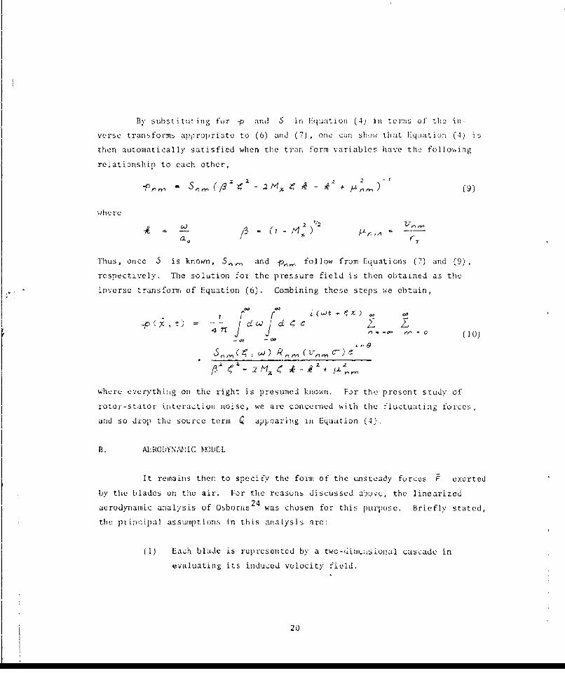
By substituting for -p and 5 in Equation (4) in tenrs of the in-
verse transforms app ropriate to (6) and (7), one can show that Equation (4) is
then automatically satisfied when the tran form variables have the foljo%ýing
relationship to each other,
S, (132 - Q M, -4 +k/A
whe re
-#0 T 0) 1 ~-
Thus, once .5 is known, 5_, and -p,,g follow from Equations (7) and (9),
respectively. The solution for the pressure field is then obtained as the
inverse transform of Equation (6). Combining these steps we obtain,
IV
x4 rJ j ' fi•7C rfl- (10)
trO
/S 42+ 1•J- + -i
whcre everything on the right is presumed known. For the present study of
rotor-Stator inzteraction io1ise, we are concerned with the fluctuating forces,
and so drop the source term Q appe;ari 'g i, Equation (4).
B. AL RODYNMIlC NOK.EL
It remains then to specify the form of the unsteady forces F exerted
by the blades on the air. For the reasoas discussed above, the linearized
aerodynamic analysis of Osborne 24 was chosen for this purpose. Briefly stated,
the principal assumptions in this analysis are:
(1) Each blade is represented by a two-,im usional cascade in
evaluating its induced velocity field.
20
(2) The steady part o7 the circulation about each blade, and hence
its influence on a neighboring blade row, is much greater than
the Lusteady circulation. The latter is neglected, along with
any, associated shed vorticity.
(3) Unsteady velocity gusts parallel to the blade chord are
neglected. This is safe p~ovided the steady state angle of3]
attack is small, which is implicit in the linuarization.
(4) Isolated two-dimensional airfoil theory is used to estimate27
blade response to gusts perpendicular to the chord.
As in the original analysis hy Kemp and Sears, Osborne considers a
single stage consisting of a stator followed by a rotor (see Figure 12a).
Since we have aqsumned a uniform axial velocity in the duct as the undisturbed
state In the acoustic model, the linearized aiialvsis is strictly appli.cable
only to stages with small stator stagger angles. Three interaction mechanisms
are considered:
(a) Rotor unsteady lift fluctuations due to its passage by the
steady upstream stator loads.
(b) Rotor unsteady lift due to its passage through the viscous
wakes shed by the upstream stator.
(c) Stator unsteady lift due to the passage of the steady rotor
loads.
For brevity, items (a) and (c) are usually referred to as potential inter-
actions since they would be present even if the fluid were ideal. Item (,
referred to as the viscous interaction, requires the presence of fluid friction.
The potential interaction analysis involves the blade aerodynamic response to
a generalized Kemp-type gust upwash, whereas the viscous interaction is modeled
as the superposition of responses to a frozen sinusoidal gust.
21
The sectional lift per unit span on the zeroth blade given by
Osborne f0r each of the above mechanisms may be symbolically expressed in
blade-referenced coordinates as
.r) jZ X e (ila)
I - i--:(lc
LK It) 'u I 1½
where X-1 = XL and similarly for Y, and ?)
The subscripts R and s refer to a blade member of the rotor and statorr. ...,ow , r s e t v y .11-r .. . ... .. .n. 1 ... .. h* , r.. o• -1 , .- 1 474. .. ..
equation numbers refers to their corresponding interactions (a, b, c) above.
The Xf , Y, , and Z, are the amplitudes of the fluctuation at each harmonic
of the fundamental frequency, whether z), or 5 . (Mo9te: since we are not
explicitly concerned here with the noise field generated by the steady rotor
.oad, the I = 0 term in [Ila, b] is ignored.) These coefficients are given
explicity by Osborne as functions of blade row stagger, spacing and operating
conditions. The full functional relationships would needlessly confuse the
analysis that follows, and so they are given in Appendix B. Since Osborne's
model is a two-dimensional ono, x1 , Y1 and 2. are independent of spanwise
location in his analysis; in the strip-wise apnlication of his results to our
annular duct model, they are assumed to be implicit functions of the radial
coordinate r shown in Figure 11.
The fundamental frequencies zA and V, correspond to the radian
frequency with which a rotor blade (stator vane) encoLuters a stator vane
(rotor blade). In the cascade model, this is related to i:he rotor tangential
velocity divided by the stator vane (rotor blade) spacing. In the present
circular duct mudel, this translates into thie product of the stator vane (rotor
blade) numtber times the angular velocity of rotation, i.e.,
22
rrfl - r r (12)
where V and B are the numbers of vanes and blades, respectively, d5 and
2 their spacing, and -a is the shaft frequency in radians/sec.
C. COMBINED AERO-ACOUSTIC ANALYSIS
Equation (4) shows that the contribution to the source distribution
S C r ,) from these fluctuating forces per unit span is in the form of
minus the divergence of the fluctuating forces per unit volume, expressed in
duct-fixed coordinates. That is, the blade rows are imagined replaced by a
fictitious distribution of acoustic dipole singularities, stationary in du.ct
coordinates, whose magnitude and phase are in accordance with Equations (Ila-c).
To determine this distribution, some asumotion must be made regardini7 the
spatial distribution of blade forces in the axial (x) and azimuthal (G) co-
ordinates. For simplicity, we have initially assumed each blade (vane) to be
represented by a line dipole located at its mid-chord. (More sophisticated
models employing a chordwise distribution of loading can be treated, as this
assumption is not crucial to the acoustic analysis.) Noting that Osbor-ne takes
the rotor as having velocity U (-Sir) in what we define as the negative (9
direction (Figure 12a), the fluctuating force field correspond'tng to Equations
(lha-c) may then be expressed in duct-fixed coordinates as
.- Xe C V s (13a)
I i- LVO9 8-1 .1 r~t) I a -1 L dr + fl------
'Y,,j d rA(lt~ SrGat- 'uu "6&c*X - X') (13b
2:-Z. eV ( ( (l3c)
where x1 , xa are the axial locations of the stator and rotor dipoles, vTe
dipole axes are perpendicular to the rotor blade (stator vane) chord lines,
23
-. - - --l- f a q . r . ~
hhich, in turn, are inclined at an angle o-.c L, from the axial dircceLion,
as in Figure 12a. Hence, the divergence of the forces occurring at toe rotor
can be shown to be (neglecting any contribution from the radial direction):
1 CAS ~~6~±>PI(14)
and for the stator,
V - ( t C , &ra$ >?, - (15)
Substitution of Equations (13a-c) into the above expressions gives the
following contributions to S from each mechanism:
,JV0 lvcsn ,- t 4-fl(- x
SV F X, e r6 (0o nI b
z ... • .- (X - -lcýcdt (IX -•
11 dx(16a3
Club
+ ---- n - n ) Xh XR) -the axrs er 2
-V-1 '(.mat. 2Tt Lt J6)
4 4vV' Ct, 6x - -S (16e)
SubstitutiulQ 1:quation, (16a-e) in ()then gives the expansion coefficients
24
.2 ( • , -- 4 r 7 - VN8l ri
c S ( c . • o - N B ! ) N I3- V ( 1 7 a )
v (e7b)
6 'Q (17c)
where the sum over the integer N has replaced that over . The notation 2;
indicates that Equation (17) should be viewed as ni being a fixed integer and
ailQwiFig only those tcims in thc sum ovcr N 'which give integral values of 2
This restriction arises because of the following identity which is used in the
derivation of Equations (17a) and (17b).
8-, -(lW•.V *,)3- :- V, N 2 V + ,i = N8 N o ,± ' 1, t -Z .
7 e -~0 O'r'P��~ r 5; -
Similarly, in the case of Equation (17c), use was made of
v- C V(-B V) v Aj EN J.B - .i NV N 0, t Y, t 2,...
e
Physically, these identities reflect the phase cancellations in the duct which
allow only a restricted set of loading harmonics to generate a given azirnuthal
mode.
25
1. Pressure_ Mode Amplitudes
Substituition of Equation (17) into (10) gives the desired solution
for Lh2- acooutic pressure field. The integral over 4 is rretdered trivial by
the I rescnce of the delta functions in Equation (17). The integral over
can bc handled in a straightfon,;ard manner using contour integration in the-
complex 4 plane. Thu integrand exhibits two simple poles on the real axis.
The physical requirement that all waves generated by a row should iropagate
away from it determines which, half-plane the poles should be considered to
lie in, and the value of the integral can then be found from residue theory.
For the sake of generality, pressure waves generated in the upstream
direction 'U either row are referred to with a superscript "u", and those in
the dowýtstrcam direction w1IL a "d". A bubscript of either 1 or 2 will be
used to denote whether they originated at the upstream or downstream blade row
(see Figure 13). (in tnis simplified model, no allowance is made for the re-
- ALtiUL Ut Li,.,LIs5aUI ut wave. by a neuighboring row once they are generated.)
This formalism allows us to present results for either the stator-rotor case
discussed thus far, or the rotor-stator case to be discussed shortly, within
the same context. Then, each harmonic of the pressure field is found to con-
sist of four sets of waves as given below:
- R Z 2: P ,,, ( ) e Via)
/1m,0a+ • tP n zi,,% ,.,(1+81-"fl 2 rl~q 2
LA L
where
•o N•Sns>o .lm• = /3- A-_ pA.*,• 2
26-0~'4'-*-.-
•! is the particular harmonic of blade passage frequency being considered.
Thic values, included in the sum over the azimuthal and radial mode numbors,
n and rn , will be discussed shortly. Equations (lSa-d) lhold regardlcss of
the relative positions of the rotor and stator. This need not be specified
until the mode amplitudes •f ' , which are in general complex, are calculated.
For the stator-rotor case discussed above, these are:
-k t
ci>~ 2 2 ( (1092Ca3
€where
P, -- ±, N, ±- * 2 , •
qni
(A. d 1
q~n4 -rr rr ,63 7-&,• " (1 t)
+ t Q 4" Pk M 2 ,X) (X,•,o) + Y- - -
whereS= P41 -iav. N.N¢ .2 = + ,+ .
The upper signs apply upstream, and the lower signs downstream.
In many applications, particularly high bypass ratio fans, the per-
tinent geometry is that of a rotor upstream of a stator (outlet guide vanes),
The same three interactions (a, b, c) listed at the beginning of Section Iii-Bare still involved, provided one interchanges the words rotor and stator.Rather than having to redo Osborne's entire analysis, the appropriate forces-,can be obtained from his present expressions using a simple transformation Widiscussed in Appendix B, and the results written down directly:
27
.. A~JlWl* ~ ..4baa.4 m1 &t2 it.-.,.-
-•,• 4rtr,. / A' ... ! L (lgcii X
2A 1
where
and
•: "(.•,• • -• ) 'xs A,
where
LLV J=N N O, z i z. •
Equations (18a-d) express the pressure field as the superpositio, of
the same spiral duct modes studied by Tyler and Sofrin, 4 and Morfev.' 6 Note
that the rotor-generated field is made up of modes with azimuthal order
NýS - )V , where N; Sfl is the acoustic frequency and ,IVtl the blade loading
frequency. The stator-generated field on the other hand is composed of modes
with azimuthal order j 5- AV , where both the acoustic and vane loading fre-
quencies • -1fl - N.BD.. .Tese rules for determining the azimuthal modes
over which one must sum in Equations (18a-d) are a result of the delta functions
involving w in Equation (17) in conjunction with the special relationships
between ri , N and A" given there. Interestingly, one can see that the rotor
and stator always will each excite the same set of {nv} modes. These obser-
vations hold irrespective of which is the upstream row.
28
[Here we are concerned only with the radiated field, and so only those
modes above cut-off, i.e., for which -k, in real, need be considered. This
allows one to pu;t an upper limit on the value of the radial index M , for a
given frequency w and azimuthal mode number r . (The form of the result for
modes which are cut off is the samc as (18), except that -A,_, is then
imaginary; its bgni is determined from the physical requircment that th(* mode
decay, rather than grow, exponentially.)
The mode amplitudes given by Equations (19a-d) are singular right at
the cutoff condition for any one mode, 4 = ,e,, , as first reported by28
McCune in his study of the disturbances generated by the steady loading or,
an isolated rotor. In References 22, 23 and 25, which treat the aerodynamic
and acoustic fields simultaneously in a two-dimensional cascade model, no such
resonance is predicted since the unsteady loads (which we have assumed as given
a l)rioriJ apparentily \anisn at this condition, due to a strong interaction
between the two fields. The experimental results discussed below and in
SecLion 11, however, indicate that the sound levels are significantly higher
near such a condition.
2. Sotnd Pressure Level and Total Radiated Power
On:ce the pressure mode amplitudes, #p . . have been determi;ned from
Lquation (19), expressionis for both the mean square pressure at any point in
the duct and the total radiated power are easily derived for any given frequency.
We denote time averages over one blade passage interval by < > Then since
everything is harmonic in time,
a j •j"i'La •2 20)(2L.
where
29
arid -c i I s the Inagni tride of the sutir of the signals from both rows, i.e., the
Coe t'iCierlt of C.t in Equation (21), after substituting from (18) and (19)
as appropriate. The result is eastly shown to be:
",Olt (.4,.
Ik, z (22L•.d ±d
, Z Z.v r, ,.fl ,, 1 I%
The last equality flollows froni the fact that the two blade rows aIlway's •NCIL
the same set of [n m) modes, (but with different amplitudes, of course).
Note that (-P") is a function of z,, z ,ore, and 0 , but is independent of
tinc; tho depcndencc on x and & will also dfsappear in situations where only
one mode is excited. The sound pressure level, 51L, then follows from
$PL ;oLo2 1 ( 23)
jheC- -P, 1 2 x 10-I dyrre/cm2
To obtain the total sound power radiated along the duct, P •d , we
mtst evaluate (Reference 6)
2,n
P + M [L 100 a M"I. <Lt +- <. J> rd "dO
(24)
where L, is the axial tomponent of the acoustic pertarbat ion velocity. The
last term is proportional to the Integral of Lquation (22) over the. duct cross-
section; it simplifics considerably due to the orthogonality properties of the
trigonometric and Bessel functions arid the fact that, for two coaplex
quantities,
30
. -
ABIq S .2. 1I161cao 4at 13'tB
The integral of d.p ½ ' then reduces to
(25)
The other terms in Equcition (24) irvolve the axial velocity in some
form. For every pressure wave with amplitude -pý-6 there is a corresponding
velocity wave with the same spatial and time dependence and an amplitude of,
say, The two amplitudes can be relared through the axial component of
the momenLun equation:
.+ - - (26)
wiud., rquircs that
CLd d CL 13 A4 rl- ,. . ,.,a ... , , , - -(27)
The quantity RA"• may be thought of as the dimensionless acoustic admittance
of an [,,,• ) mode. For the plane wave mode with no axial flow, n I tm i o
it reduces to ;i, as expected. Since . is a real, constant multiplicative
factor independent of x, r and 6 , the contributions to P"' from the first
two terms in Equation (24) can be written down directly from (25).
The complete result can then be reduced to:
1(,M2 \,q-
n aj c• (a 1,,,,,, -Ao,,_, (28)
which is written in such a way that P' and Pd are both positive, i.e., power is
always radiated away from the stage.
-- .. . .IV. 4A- U a & W & ai n e n ... .,
The terms involving the squares of the mode amplitudes represcnt the power put
out independently by each blade row, assuming only its radiation was pIeCsent.
The last term represents an interference between waves emanating from the
separate rows; this would be zero if the two blade rows radiated independently
of one another, i. e, if (arg -P1A arg -, ) were random.
If the acoustic interference effect is sufficiently strong, it may
be possible to "tune" the rotor-stator stage to minimize radiation at a given
frequency by adju--sting the inter-row separation Ix,, -xzl (see Equation (19)).
To achieve maximum benefit, Equation (28) indicates that should ap-
proximately equal ).co',j . However, most modern turbofans are designed with
maximum rotor-stator separation, subject to size and weight constraints. This
usually results in negligible potential interactions between rows (they decay
cxponentially); practically all the noise then results from the viscous w.,,ake
impingement on the downstream row, i.e., in our notation, dp,'
These arguments suggest that moving the rows closer together until they play
roughly equal roles may lead to nolse reduction at a given frequency, if their
signals can be made to destructively interfere. This would probably be useful
only in situations where the acoustic field was dominated by a single
mode. Whether the benefits of such a scheme could be realized in practice
would depend on several factors not included in the present model. One would
also have to consider if such an optimum separation would have an adverse af-
fect on the other harmonics in the spectrum.
Useful qualitative conclusions regarding the variations in upstream
and down.stream radiated power which result from changes in axial Mach number
and frequency can also be drawn from Equation (28). The arguments below apply
to radiation from a single rotor as well as from a rotor-stator pair, due to
the absence of transmission and reflection effects of the other row. Hence
for the sake of simplicity imagine the mode amptitudes of one row, say the
rotor, to be dominant over those of the other row. First we consider the
situation with no mean flow. In this case, Equation (27) shows
32
-.- ..-. m........... . . .
14 = - (29)
and the power contained in any one a,• mode, call it P: is proportional
to (from Equation (28)):
Now, from Equation (19) we see that the only thing differentiating o
from J-pý,,j is the sign of that term in the integrand beginning with sin a,
If the integrand is not very sensitive to variations in radius, Equation (30)
can then be written approximately as
~n W
which, after soeme ie-arranfgemcnt gives
Pd ti "I rTJ4~n L2 .____ _ ~L(31)
4'~~~ r-c.o' /
This result is in agreemnent with that of Morfey in Equati-on (09) of Reference 6,
if there one sets t-, o , interchanges n and ni , and notes that in hi:; nota-
tion, 6/ka.~ equals c-4 R/, }o in ours, Equation (31) indicates that cven
when n~~ , equal. amounts of power do not radiate to either side of the!
blade row. This results from the fact that the relative angle between thQ
dipole axis and the propagation vectors of the acoustic mode, sa)' 01r is
different on the two sides of the blade row. The situarioin is -;hown
schematically in Figure 14.
The geomctry of Figure 14 suggests that. this asyrimentr, i~n radiated
power should disappear for modLS propagating very near thIe duý..t axis, whichi
happens well above cut-or(. In this cas.e
33
I
- -0 A"--k(2
and the ratio in Equation (31) approaches unity.
In fact, this can be shown to be true in the more general case with
axial flow; Equation (27) then yields,
,•"' ,(33)
The first factor in Equation (28) then becomes
and it can be shown, again using Equations (19' and (32), that
, < (yI - l) /(34)
Hence, while n7", and P_ will still depend individually on ,147 , their ratio
I eý (35)/3 1 - -k•,
will always approach unity for modes well above cut-off, again in agreement
with Reference 0. Care should be taken not to apply this result very near
the condition of transonic axial flow, M,, - I . Here the upstream radiated
power will vanish, whereas that in the downstream diroction remains finite,
in violation of Equation (35). This is because the linearized analysis on
which these results are based is invalid right at the transonic condition.
D. COMPARISONS OF THEORY WITH EXPEPIMENT AND DISCUSSION
This section presents comparisons between numerical prediction.s from
a computer program based on the preceding analysis and the acoustic data de-
scribed in Section II. Unfortunately, as pointed out in the discussion of
Sec.tion II, acoustic data could be obtairted only for the tourth and fifth
S~3.
harmonics of blade passing frequency. As seen below, this seriously hampers
one's ability to draw meaningful conclusions concerning the model's validity.
The basic inputs required by the computer program are the geometries
of the two blade rows, the steady lift on each of the blades, and the drag co-
efficient of the upstream row, which in the case of the present experiments,
is the rotor. Since at the speeds encountered in the experiment compressibility
effects should be negligible, and the hub/tip ratio is large, a two-dimensional
incompressible r.leory can be used to relate the lift and drag on each blade to
the turning performance and viscous losses across each row. For example,
Horlock32 has shown that the drag coefficient, G. , of each blade is related
to the total pressure loss coefficient, 4Cr , by the following
L -C P 4 ,C3. (36)
where ORn&/SPRN
I, (37)10 VM,
TOTAL PRESS URE LOSS ACROS5 ROWA2 a (38)
,, is the mean flow angle, cL the blade spacing, c the semi-chord, and p the
fluid density. It is important to note that/ 3rn and the total pressure loss
must be measured in coordinates fixed to the blade row. Since ce/3- =V_
V_ being the vector mean of the velocities upstream and downstream of the
blade row, and dt Equation (36) becomes:
m A, r (39)
where B is the number of blades and everything on the right hand side is
either knowvn or measured.
Also, the lift coefficient on each blade, 0 L can be obtained from
the turning performance through:
35
c -8,- -,- r4-/32 cr V1,-c Cra (40)
where ,3 and /6 are the upstream and downstream flow angles, respectively.
Letting
o2 4 1 (41)
where z, and it are the tangential flow velocities, again measured relative
to the row, and substituting for d ,13_ and C. from above, we obtain
7r [ -'a - ., (42)sc "T-• •v zc
Now the lift force is actually put into th: rotor-stator interaction noise
program in the form of the Glauert coefficients A. , required by Osborne's
theory (see Appendix B). The first two of these, R. and A, , are respectively
the blade angle of attack and the ratio of maximum camber to blade semi-chord,
assuming a circular-arc profile. They are related to :L by
C -a ",7 (A , + 4 ) (433
Since the angle of attack R; is simply the mean flow angle minus the known
geometric blade stagger angle, Equations (42) and (43) are sufficient to de-
termine A, ; for n greater than one, the P,, are assumed to be zero. In this
way the AF. are computed in such a manner as to use the actually measured
steady loads in the Osborne theory.
For the present acoustic experiments all quantities on the right
hand side of Equations (39)-(43) are either knowni or measured in the case of
the rotor, for which data were taken were over a wide range of conditions in
the previous program. I Unfortunately, since stator performance data were
obtained near rotating stall inception, they do not include the range of inlet
conditions covered by the present experiments. Consequently, stinatr turning
performance uas inferred from design data made available by the mantuacturer
for the corresponding stator in the comp'ete J-79 engine. The outlet flo¢w
36
angle at design was assumed to apply for all incidence angles away from the
design value (corresponding to a high solidity approximation). The outlet
angles at the off-design stator stagger angles used here were assumed to
differ from tha designi value by the same amount as the stagger angle differed
from the design stagger angle. Viscous losses were assumed negligible for
the stator; this is a safe assumption since tIC-, has a relatively weak influ-
ence in Equation (42) and the C0 of Equation (39) is not needed for the down-
stream row. The rotor mid-chord location was chosen as X = 0 . Hence, the
coordinates of the piobe in Figure 1 were X -. 979 ft., r = s 1.?21 ft.,
and eo 00.
Due to the large hub/lip ratio of about 0.8, the dimensionless
steady lift and drag co,;•ficients used by the program were input as cornstants
independent of radius. These were computed from the radially averaged turn-
ing and loss data ot Heterence 1. The lift and drag forces do, of CO,(.,-
vary with radius, because all the velocities scale with the rotational speed,
fir To check the validity of using the radially averaged coefficients, one
case was also run with a four-point radial distribution of these coefficients
(also measured in Reference 1). This produced only minor differences in
the results.
Figure 15compares the expernimental measurements of r.m.s. wall pres-
sure described in aection 1I foi the fourth harmonic of blade passage frequency
with the computer predictions for the mean stator stagger angle of 37.20.
The axial flow velocity and rotor rpm were varied in such a way that the .
relative rotor inlet angle, and hence also turning performance, of both rows .4
was held constant for all conditions shown. Figure 16 shows the same compari-
son for a mean stator stagger angle of 28.20. 1
The comparison of absomte levels is seen to be rather poor, although
the shapes of both curves are in general agreement. For example, in Figure 15 S.
both experimental and theoretical curves are characterized by two rathir well-eA
defined peaks, at approximately 1170 and 1445 rpm in the experiment, and 1.150
and 1415 rpm in the theory. Similar behavior is exhibited in Figure 16. As
37
A
explained under the discussion of Section 11, discrete-tone noise signals
could be obtained only at the fourth and higher harmonics of blade passage
frequency in the accessible rpm range of the annular cascade experiments.
The left hand peak in the theoretical curve corresponds to the operating
point where the r = 22 azimuthal and rn = I radial order mode for the fourth
harmonic of blade passage frequency exceeds the theoretical cut-off condition
and begins to propagate. The peak at the higher rpm corresponds to where the
,l = 22, rn = 2 mode begins to propagate. These peaks are a result of the
acoustic resonance that :.ocurs at the cut-off frequency of'any mode, due to
the vanishing of -kin the denominator of the modal amplitudes ' (see
Equation (19)). The height of the theoretical curve is limited only by the
precision of the computer. The level and shape of the experimental peaks
in these regions are heavily influenced by factors not included in the. ideal-
ized model, e.g., non-linearities, viscous effects, and radial variations in
axial velocity. In view of this a small discrepancy between the locations
of the experiment:,i nnd theoretical peaks, here about 20 rpm, is to be expected.
Note that the pressure levels rose slightly from Figure 15 to
Figure 16, probably a result of tilting the stator load vector closer to the
angle of propagation of the acoustic mode, as well as a modest increase in
flow velocity. Again, it is encouraging to note in this regard that theory
and experiment rose by roughly the same amount
Figuro 17 contains limited data for the fifth harmonic n1oise of Lhe
same rotor-stator pair as Figure lu. The fifth harmonic excites propagating
modes at a much lower rpm. In this case only the n = 14, I - mode is
present, the rpm at which it theoretically exceeds cut-off being just to the
left of that shown. in the figure. Here, the shapes of the twc curves are
only mairginally similar, and the discrepancy in absolute levels is even wider
than in Figures 13 and 16.
This discrepancy in absolute level between theory and experiment
bears further discussion. For the experimental rocor-stator stage having
46 blades in the rotor and 5A blades in the stator, the nI = 22, ,n = 1,
38
2 modes in Figures 15 and 16 are generated by the third loading harmonic on
the rotor in concert with the fourth loading harmonic on the stator (see Equa -
tions (19c, di). Moreover, computer resuits indicate that at these conditions
the potential interactions between rows are negligibly snall in comparison
with the viscous interaction. Hience, the question is reduced to how well the
model can predict the noise resulting from the fourth loading harmonic on the
stacor induced by its passage through the rotor viscous wakes. (Figure 17
involves the fifth harmonic of stator loading, and hence is an even more
severe test of the model.) Since the velocities involved are all low enough
to be considered incompressible, we are essentially dealing with the original2,3
Kemp-Sears model to Thich Osborne's analysis reduces in this limit. It is
felt that the following are the most likely sources of the discrepancy:
a Poor modeling of the viscous wake defect at the higher harmonics
* Inaccuracies in turning performance and loss data used as inputs
0 Inadequacy of strip-wise application of isolated airfoil theory -•
in predicting unsteady loads
Each of these is discussed individually below, beginning with the last.
The ad hoc application of a strip theory aerodynamic analysis for
predicting unsteady loads in a three-dimensional annular flow is open to
question, although the large hub/tip ratio and large number of blades in this
case weuld seem to justify it. Also, since the solidity zatio, 2C/Q& is
near unity, the use of isolated airfoil theory in estimating these loads
introduces some error. These questions are particularly crucial with respect
to phase variations in loading along the span, as these critically affect
the radial integration involved in the modal pressure amplitudes, - inn
Equation (19). It is difficult to assess the importance of these approxima-
tions in the absence of any experimental data on the load fluctuations, or0
a truly three-dimensional annular cascade theory for unsteady flow through a
blade row.
39
The inaccuracy involved in estimating the steady loading and viscous
losses on the rows is also difficult to assess. The principle reason is that
such data as were obtained were measured with the row operating in isolation,
since at the time their use in the present investigation was not envisioned.
Hence, the performance of both rows may have been somewhat different from
that assumed. This could significantly affect the potential interactions.
Since these were found to be negligible as noise sources at these conditions,
a strong variation in loading would probably be needed to appreciably change
the acoustic predictions. The prediction of viscous wake interaction, how-
ever, might have been considerably improved if more detailed knowledge of the
blade wake structure had been available. This is discussed at more length
below.
With regard to the wake modeling, both Osborne's analysis and the
previous work of Kemp and Sears made use of empirical laws for the wake width
and velocity defect suggested by Silverstein et al,53 based on isolated air-
foil data. in particular the decay of the wake centerline dynamic pressure,
q, . is assumed to follow
_ - -0.4
where 3 is the free-stream dynamic pressure, x the distance downstream of the
blade mid-chord position, and c the seri-chord. From this, the centerline ve-
locity defect, u", , was inferred, assuming it to be a small perturbation of
the free-stream flow. In the present experimental configuration, there is
roughly a one semi-chord separation betwee. - . rotor trailing edge and the
leading edge of the stator. Equation (39), in conjunction with the loss data,
indicates a rotor C0 of 0.16. For such a high drag coefficient, Equation (44)
predicts a negative value of dynamic pressure, and is clearly inapplicable.4
Partially for this reason, and also because it was feit that the
radially averaged loss data were perhapýs unduly influenced by viscous losses
at the inner and outer duct walls, the value of C0 used in the calculations
presented here was lowered to 0.10. To indicate the uncertainty involved in
40
estimating u, , an alternate correlation proposed by Dittmar (Reference 17Equation (J,), and based in part . , the cascade data of Lieblcin and Roudebush, 4
was evaluated for the same conditions. It indicated an increase in o., by a
factor of about 1.5. Since the unsteady loading is proportional to u-~ , and
only one mode is piopagating over most of Figures 15 and 16, one would expect
this to raise the theoretical SPL by about 4 dB.
In addition to this uncertainty, a surprising variation was noted in
the :alculations. That is, when C. was lowered from .16 to .10, there was a
rise in the predicted viscous interaction force, and hence dult wall pressure,
in sharp contrast to the conclusion of Kemp and Sears'3 that such loading ap-
pears to be linearly proportional to c, . The observed behavior can be traced
to an exponential factor in the load prediction (see Appendix B (c)) whose
argument is propoitional to minus the product of C. times the square of the
load harmonic index. Clearly, for the high drag coefficient and load harmonic
inde•xt of .1 ,r t here this ux.uI+elLLJ..± uav domtina(tes aim' linear vya iar ion.+
The above anomalous behavior strongly suggests that the viscous wakes
are not modeled accurately enough to predict the higher loading harmornics on
the downstream row when the rotor and stator are in close proximity to one
another, and the wake structure is accordingly changing rapidly. Table Ifurther supports this contention. The first t'o entries in the frsr column
3,24give the velocity defect profile assumed by Kemp-Sears-Osborne, 4 and that
originally suggested by Silverstein et al, as a fit to their isolated airfoil
data. Here L is the velocity defect at any distance y from the wake centerline,
and Y is the wake half-width, The last entry is suggested by the present
authors as fitting the Silverstein data nearly as well, at least witllin the
experimental scatter of about ±.10 in cL/,u0 sho,,wn in Figure 42 of Reference 33. X
All three are normalized in such a way as to produce the same total momentum .1
defect in the wake flow. The second colunn gives the relative magnitude of
the Ith rharmonic in the Fourier expansion of an infinite train of such pulses
spaced a distance d3 apart. Since this is the only change that would be in-
volved if a different profi e were assume.J, the influence on the theoretical
predict ions can be easily assessed. The first entry is the exponential discussed
4.
44
, (-, # 11÷
+ +
0
., 'I•-
4-, , - ,-
.. - ,, II '
4)40
I0
I0w'L . -. . ..
S- I U
above, Lut written in terns of Y r•ther than Co for the sake of simplicity.
The r:uxt t•o <:ntrJes show how this factor weald change i£ one or the other o17
tile substitute profiles had been assumed. Th• resulti•;g chan•es in the pro-
dictions art. -.,ho•l in the last column for "Y/• ¢0• •, (:'•::tuall:," }'./c• •, o.•
f,•r the present case of a rotor-staler) = .265.3 appropriate to the present
conditions, and the first, fourtt•, and tenth loading harmonics. Note that the
firsT, h.•rmonic Js r-latively insensitive to the choice of profile, bu• at
higher values of_.• sL.ch as needed here, the choice is critical, tlad tile last
profLle Leerl used [n the cai.culat, iohs, in conjun¢tiozl with the alternate
estlma:te of • discussed above, it is seen th-lt •.h-• theoretical curve •-n
Figure IS would be almost 12 dB high,:r.
It would be presumptuous Lo st'ggest that this constitutes a b,:-•ter '.;.
model for the •akc p•operties in the present case, or any other, simply bcuause
•t_• corrcLate.s better '-'it], our acoustic ,,•.' .... But it i• •ica: "hat the' prediction
of i•igher harmonics is too sensitive to the details cf wa•.e structure to be re-.
liable, and for t|•e•e we ha':e had to rely on isolated airfoil data. Moreover,recent ezperimental workZ0'35'36 haa she'.-n •hat l'.-.•' •,ake propertie.¢, for cascad-
ed azt'foils and rote• blades can dLffer significantly from those for at: Jsolatwd
aixtoil, tience •t i0 felt likely that the theor)' could benefit from a ••filLe.d
viscous wake model •;hich better reflects the true situ:•tion. Also, if they
should prove possible, co'npariso:•s of the theory against acoustic data for the
lower harm'•.:|•cs in the spectrum woctld be v(::-> yah:able. These are :cs5 sen-
sitive to d•'tailed ,•hanges in wake strut:urn:, and would alio•' a better assess-
me::l of the validity c£ •:ther por:ioes of the theoretical model.
E. ADDITIONAL NIJ%{LRICAL RLSUL]'S
In addition to the ebove comparisons with experiment, which all in-
volvo incompressible flow, some calculati,)ns have been performed to show tile
influence of compressibili•,:y on the radiated nois,:. One of the test cases
presented by' Clark, et al. (Referenc• 19, Vol, Ill, p. 59) involved the ,'al-
cutation of the upstream pressure amplitudes generated by the potential inter-
action on the upst•eam s• tor of al: i:ll¢l stator-rotor pair. Tile present ,:-
4•
•,'•
program was run using the same input conditions as given there (see test
case #2, subroutine package AAB!A). Briefly, the stator and rotor were housed
in an annular duct with hub/tip ratio of .35, and axial Mach number of 0.5.
The rotor (1S blades) had a tip Mach number of .875 and was located a distance
c,1/s downstream of the stator (10 vanes). In this case the potential inter-
action on the upstream stator was dominant. The amplitudcs
I' I / .
as used by Clark, et al. 19 are compared win.. the present predictions in
Table 2.
Table 2
COMPARISON OF MODAL AIMPLITUDES COMPUTED BY CLARK ET AL. 19
WITH PRESENT THEORY
C rl Clark et al. Present Theory
1 4.72 x 10 8.92 x 10-
3 7.46 x 10 2 3.83 x 10²
S1 .54 x 1.0 "5.36 x 1"IF- -_______ __9______
_F -21S+5 I S.07 x 10 1.91 x 10 ,
3 8.94 x 10⁻² 3.84 x 10
This particular calculation in Reference 19 also assumed a line
dipole model for the blades, and so the differences in the predicted values
are largely a result of using the Osborne rather than Kemp-Scars aerodýnamic
analysis. As one might expect, the inclusion of compressibility (the relative
Mach T,.umb,::r at the stator was about 0.5) had a noticeable effect, generally
dccreasirg the modal amplitudes.
44
In the acoustic experiments performed under the current program, the
fundamerntal blade passing tone could not propagate owing to power constraints
in the annular cascade (see Section II). However, calculations indtcate that
it should begin to propagate above roughly 1160 rpm. To study its behavior,
and give some idea of how the theoretical predictions vary over a wider range
of conditions than those above, the calculations in Figure 18 are presented.
The inputs are the same as in Figure 1S, except that the rpm and N, were in-
creased, again proportionately, into the subsonic regime. Thus, when this
tone first begins to propagate at the left "f the figure, the relative Mach
numbers of the rotor and stator are approximately .15 and .11, respectively.
,hei 8700 rpm is reached, these are .77 and .56, and the first four radial
modes of the r. = -8 circumferential node are propagating. The rpm at which
each of these starts to propagate is shown at the bottom of the figure.
The upper curve gives the variation in 5PL at the same location as
before. As exijctted, thule is a large _i1't24abe in sig;'ai over the fourth
harmonic of Figure 15. The lower curve in Figure 13 is the total power radiated
in the upstream direction. Straight line segments have been used to connect
the computed points for ease of visualization only, and should not be assumed
to accurately depict the true curve. The curves exhibit a rise just above each
cut-off frequency, due to the acoustic resonance for that mode, as discussed
previously; again it should be emphasized that the levels computed very near
these frequencies arc open to question because they represent singular points
in the solution. In fact, the rise becomes harder to resolve as rpm is in-
creased. This results because as increasingly higher order radial inrues get
turned on, the integrand in the radial integration in Equation (19) osciliates
more. The value of the integral itself thus approaches :ero, anl so one must
be extremely close to the cut-off frequency before the pressure amplitude begins5
to diverge.
The behavior of the SPL curve in Figure 13 is much more unpredictable
than thai. in Figure 15. *his is because over most oi the rpnm range mure than
one mode is propagating, and so the interference between modes described by
Equation (22) cones into play. No doubt at some other point in the duct this
45
curve would look quite different, due to its complicated dependence on observer
position and frequency. At the higher" rpm values the curve begins to smoot.i
out somewhat, probably because as the signal is distributed amongst more modes,
the constructive and destructive interferences tend to cancel one another.
Thie curve rupresenting total radiated power is much more well behaved,
since it represents an integral over the duct cross section, thus removing any
delpa.dence on position. With the exception of the resonance peaks, it exhibits
a smooth -rise as relative velocity is increased, as expected. The interference
effects between waves from the rotor and stator described by Equation (28) do
not arise, since the computer results again indicate that >
The leveling off and subsequent decay of the curve in the higher rpm region
is not surprising. Upstream radiated power must go to zero as a soni,: axial
flow velocity is approached; hence the presence of a maximum in the subsonic
regime is to be expected. However, as Osborne's theory becomes more approxi-
Mate as tI= LVC i:'iia number is Jncreased. whether the location of the
peak is accurately predicted is open to question. Subsequent to the completion
of the present worok, Amiet3 7 presented an approximate analysis of compressible
unsteady airfoil theory which also makes use of asymptotit techniques. His
analysis complements Osborne's in that it becomes more exact as the Mach nunber
and/or reduced frequency increases, and so should prove useful in the higher
subsonic regime.
The computing time needed to generate the numerica[ results in
Sections Il-1, E: above on an IBM 370/ld8 varied bcween approximately I and
10 seconds per point, depending primariiy on the numb.:r of propaga ing moles.
F. CONCLUDING REMAIR KS
A compressi'lc two-dimensional analysis of the aerodynamic forces
generated by roto,-stator inrteraction has been matched, on a strip-theory basis,
to the well known three-dimensional annular duct acoustic modes. Lxpres - ions
have been derived for both h2 mean square pressure at any position in the duct
46
and the total power radiated at harmonics of blade passage frequency. The
mean square pressure signal is seer, to be subject to interferences between
the various propagating modes. The total rad:ated power is the sum of inde-
pendent contributions from each mode, but is still subject to interference ef-
fects between waves generated by each row within the same mode. These are
evaluated easily on a computer in terms of stage operating conditions and
geometry.
Experimental acoustLc data were taken in the annular cascade facility,
as described under Section II, to provide a means of assessing the validity
of the theoretical model. Data on blade row steady-state performance and
losses had been taken in the annular cascade facility under a previous program.
These were used as inputs to the theory to calculate SPL at the outer wall,
and the results were compared with the acoustic data for two configurations of
a rotor-stator pair. Unfortuunatcly, power constraints in the rig allowed only
the fourth and higher harmonics to be studied, which is felt to be a rather
severe test of the theory. Although it was able to predict cutoff frequencies
and follow trends in the data adequately, the theory significantly under-
estimated absolute levels.
The most likely source for the discrepancy is felt to be in the viscous
wake modeling, which at present is based on isolated airfoil data. Recent
experimental work by others has suggested that the strvcture of cascade and
rotor wakes can be significantly different, and this is expected to have a
strong influence on the higher harmonics. It is felt that the theoretical
model could benefit from a closer examinat on of such cascode or rotol wake
data as are available, as well as an improved aerodynamic load model at high
redaced frequencies and Mach numbers.'17 It is also hoped to obtain more
acoustic data in the annular cascade facility, which has been repowered and
will now allow the propagation of lower harmonics in the spectrum.
47
SECTION IV
DIRECT LIFTINC SURFACE THEORY FOR A COMPRLSSOR ROTOR
Increased emphasis on reduction of the size, weight, and noise out-
put of axial flow turbomachinery demands improved understanding of the flow
through high-speed fan and compressor blade rows. As more dctailed questions
are asked about modern blade row performance, the essentially three-dimen-
sional character of the flow takes on increased importance. The task of
calculating the fully nonlinear, threc-dimvnsional,viscous flow through inter-
acting blade rows .s a formidable one indeed. Consequently, some approxima-
tions are required in order to obtain a tractable model, the most familiar
being the jaealization of inviscid flow through a two-dimensional cascade.
A linearized analysis of the steady, inviscid, three-dimensional flow through
an isolated rotor contains important features not present in the ccrresponding
two-dimensional cascade approximation. For example, though restricted to
lightly loaded, thin blades, it does include disturbances induced by the
trailing vortex wakes which result from spanwise variations in the blade
circulation. Also, modern fans and compressorc often operatce ith a tra.asu..ic
inflow that is subsonic ox.er the inner portion of the blade span and super-
sonic over the outer portion. At Mach numbers where shock losses are small,the linearized, three-dimensional analysis remains valid, bu, it does not
have a well-defined two-dimensional limit.28
The small -perturbation approach to three-dimensional compressor
flows~ ~ ~ ~~~J wspoceebyMun2841flows was pioneered by McCun2 who, in the sp-irit of linearized wing theory,
separated the thickness and loading contributions to the rotor disturbance
field. In his original papers, McCune treated the thickness problem for the
subsonic, transonic, and supersonic flow regimes. Later, Okurounmu and, 12,43Mcturie employed a vortex represelntation of the blade row to solve tile
indirect lifting problem, i.e., that in which the disturbance field, along
with the blade geometry needed to produce it, are determined from a prescribed
distribution of blade londing Lordi 4 4 "4 hab invest .gated the acoustic im-
plications of both of these anaiyses; the sound radiation from an isolated
rotor operating at supersonic tip speeds was evaluated for various th-ckness
and loading distributions.
48
ii
W•ile the thickness and ]oading contributions to the rotor disturbance
field can be treated separately in the linearized analysis, they are not
entirely independent. In order that there be no loading contribution to the
flow field associated with a given distribution of blade thickness, this
thickness must be distributed about an unknown camber line. The camber lines
required for the rotor to be unloaded must be determined as part of the
solution to the thickness problem , in much the same way as the camber lines
corresponding to a specified loading distribution are computed. Erickson,
Lordi, and RaeJb presented results for thickness-induced camber lines at high
subsonic tip speeds. They also have computed the camber lines required to
produce given loading distributions, as have Okurounmu and McCune.43
A major objective of the presen: program has been to develop a
linearized analysis of the direct lifting -urface problem for the compressible,
three-dimensional flow through a rotor ruw. In contrast to the indirect load-
ing problem, the direct problem refers to the situation where the blade inci-
dence and camber lincs are given, and the resuIting blade loading must be
determined. Once the blade loading is knoun, the evaluation of the rotor
flow field is accomplished in the same way as in the indirect case. The
solution of the direct problem, together with the existing solution of the
thickness problem, would permit computation of the aerodynamic and acoustic
performance for a rotor row of given geometry ac specified operating conditions.
In addition to providing a predictive capability for steady flow at off-design
conditions, thc successful anaulysis of the direct lifting surface problem pro-
vides the basis for cxamining three-dimensional flows which are unsteady in
rotor coordinates. 4
In the thickness and indirect-loading analyses, the flow field
quantities are four'J by evaluation ef integrals which express the superposi-
tio.n of the appropri.cde singularity solutions e.g., sources in the thickness
case and vortices iij The loading case. liow2ver, direct lift4ng surface
calculations entail t.he solution of an integral equation, which for a ductcd .•
rotor has a very complicated kernel function. Some progress on the direct
49"i
lodaing problem has beon reported by other investigators. Dharwadkar and
McCune have obtained a solution using a lifting-lin: approximatijon.. Namba 4 8 ' 4 9
has reported a diroct lifting surface analysis including some numerical
examples. Nanba:s approach close]ly parallels that presented here and frequent
reference to it is made throughout the report.
Our initial approach to the direct lifting surface problem was to
generalize the formal relationships between the blade camber lines and the
blade loadings which were derived in Reference 46. In this way, an integral
equation for the blade loading was obtained in the framework of the vortex
theory of Qkurounmu and McCune. This formulation of the direct lifting
surface theory produced an integral equation which not only contained the
expected complexities in the kernel function, but moreover would require
repeated evaluations of both ordinary and modified Bessel functions of large
order. The appearance of both kinds of Bessel functions is a consc'tuence
of tne way in which the trailing vortex wakes are hfandled separazeiy from
the bound vorticity at the blade surfaces.
At this point, ar, alternative formulation of the lifting surface
problem was sought by using a pressure dipole rather than a vortex representa-
tion of thv blade surfaces. In principle, the tw% approaches should result in
tihe same governing integral equation for the blade loading. Howe.er, it was
felt that an alternative derivatiun, as is often the case in potential theory
for complicated geometries, would yield an alternative form for the result.
A simpler for'm did i.ndeed result from the pressure dipole approach, the main
difference Leing the absence of the modified Bessel functions of large order
which appear in the vortex formulation.
At about the time we began to pursue the piessure dipole representa-
tion, Namba's initial report48 appeared. There are important differenccs
between our foraulation anLd hi.s. Fuithermore, the initial solution for tile
50
-so
pressure field which we obtained wici' the dipole representation failcd to
yield correct limits. In particular, the pressure rise between points far
uPstream and downstream of the rotor did not agree with that from the vortex
theory, or with Namba's version of the dipole formulation. These discrepan-
cies prompted a complete review of our analysis. A crucial revision has been
made in the pressure dipole solution which led to a limiting pressure rise
across a lifting rotor that now agrees %ith the vortex theory result, but
still differs from Namba's.
In tne material which follows, a detailed account is given of the
linearized solution for the three-dimensional, compressible flow through a
rotor, This formalism is presented riot only because of its relevance to
establishing the correct integral equation in a direct lifting surface theory,
but also because of its general importance to other aspects of the flow
through rotating blade rows. In Section IV-A, the derivation of the line-
arized equations is reviewed and a fort-mal solution of them is obtained basec
on Green's theorem. In Section IV-B solutions are found for the disturbance
fields of a point source of mass a.ra a pressure dipole. Next these singu-
larity solutions are used as the Green's functions to deteirmine the flow
fields produced by rotor thickness and loading distributions. Discussion
of the thickness contribution is included here because cf its role in deriving
a correct solution for the entire flow field, and also to point out omissions
in earlier results. In the resptctive presentations of the thickness and
loading solutions in Sections IV-C and 1V-D, the f)ow fields are shown to
display the correct discontinuous behavior across the blade surfaces and
trailing vortex wakes. Demonstrations that the results for a mass source,
a pressure dipole, and the thickness and loading problemfs satisfy global mass
and momentum balances appropriate to the noninertial reference fr.meL are
collected in Appendix C. In the final part of the main text, Section IV-E,
the governing inte-gral equation for the dixevt lifting surface theory is
derived and the progress made on its solution is reported.
51
A. DERIVATION OF MODEL EQUATIONS AND GREEN'S FUNCTION SOLUTION
In this section, the linearized equations and a formal integral
representation of their solution are developed for the flow through an isolated
rotor row in an infinitely long annular duct. The key assumptions in the
analysis are that the undisturbed axial velocity is uniform and subsonic,
and that the disturbrnce field of the rotor is a small perturbation about
the resulting helical inflow seen by an observer in blade-fixed coordinates.
Both compressibility and three-dimensional effects are included. WhAile
not a fundamental restriction in the analysis, attention is confined to
subsonic relative tip speeds. The required externsions to supersonic tip
speeds are indicated at several points in the derivations. As a consequence
of the linearization, the blade surface boundary conditions can be separated
into thickness and camber line contritutions and their associated flow field
solutions superimposed to find the overall disturbance field. This separa-
tion is effected by requiring the rotor blades to be locall> unloaded in
the thickness case and by assuming that the blades have vanishting thickness
in the loading case.
The geometry of the blade-fixed coordinates is illustrated in
Figure 19 for a rotor rotating in the negative 0 direction with angular
velocity to The full nonlinear equations for the flow through such a blade
row in a cy'lindrical coordinate system fixed to the rotor have been given bySc
WU. These equations can be linearized by writing the velocity in blade-
fixed coordinates as
where CUR is the undisturbed velocity,
A U- + CJr-e (46)
and i7 is the perturbation velocity with components -r, , , va . The fluid
pressure and density are expanded in a similar way; the undisturbed quantities
are deneted by - and /0, , the perturbation quantities by .t and/0 . Sub-
stituting these definitions into Wu' s equations and linearizing the result by
52
neglecting the products of perturbation quantities leads to the following
vector forms of the steady flow continuity and momentumn Cquations, to first
order.
0 VO + p V. (4 7.S(47)
Paying careful attention to the proper differentiation of the un.t vectors,
the component form of the momentum equation can be expressed as
, o., U d•49,.,a)
U. - 3-p (49b)
I.. -
ds 3,*
where U, = ,j¾.•-r'P and S is the coordinate alorig the helical undisturbed
streaml ines.
From this basic set of conservation equations, we can develop the
governing equations for either the perturbation pressure or the velocity
potential, the solutions of which can then be used to obtain the remaining
flow field quantities. First, the & and Z components of the momentum equa-
tions are cast in ter'ms of distance along the undisturbed streamlines and
the direction normal to the streamline and radial directions. Unit vectors
in these directions, which are illustrated in Figure 20, are
P= e0 C-4gt,-3.o± (Sob)
where ?P tan wr/,/ . The directional derivatives along 5 and a are
related to the partial derivatives with respc.:t to a and 4 by
53
as __+___j_ ~ , (SIa)
5 +- . r, U - o ,
8,___ ' w yr (Sib)
With these results the $ and a components of the linearized momentum equations
become
(52a)355
S. . . .- (S2b)
T-his form of the linearized momentum equations is useful in relating results
for the pressure and velocity fields. For subsonic flow •:herc disturbances
dec¢ay far upstream, Eq. (52a) can be integrated along the streanlines to
obtain
The normal momentum equation, Eq. (52b), plays a central role in the direct
lifting surface theory. It contains the upwash velocity, tr4 , which is
related to the blade camber line in order to derive the integral equation
for the blade loading. The above equations have the same appearance as their
counterparts in isolated airfoil theory because Lhe linearized substantial
derivative, 39 -- , is independent of radius. It s. ould be noted that the
noninertial acceleration terms enter only through the curvature of the un-
disturbed streamlines.
The governing equation for the perturbation pressure is derived by
introducing the assunption that the disturbance flow is isentropic so that
5 4
where L,, is the undisturbed sound speed. Using this relationship to eliminate
the density, and then combining (4 J. of the linearized centinuity equation
with the divergetce of the raomentum equation leads to
V -P - w(SS1
There are several ways to demonstrate that the velocity potAential
satisfies the samnc governing differential equation. McCune, 41starting in
flui'-fixed coordinates where the disturbance potentiat satisfies the wave
equation, obtains this result by transformation to the biade-fixed system.
to the same result. Here we note that the linearized momentum equations,
in the streamline-normal coordinates, indicate that the velocity components
are proportional to the gradient of the integral of the pressure along the-
undi51turbed. strcamlins,,, aa csidi fullltion. Accordingly, Ii a scalar velocitY
potential, defined such that r-V4 , is introduced into Eqs. (47) and (52a),
the results may be combined with Eq. (54) to obtain
V o (56) ,
This equation is the same as that given for p in Eq. (SS), and when expressed
in cylindrical coordinates leads to the same form of the governing equation41
for the velocity potential that McCune obtained.
The formal solution of the governing differential tquation for ci
(orv-p) is derived from Green's theorem, which states that for two scalar
functions • and G
iv
jr
V V--- d-- V (5-)
where the surface.%5 encloses the volume V and '• is the normal tc the surf;lce "'
7 directed into V . The fol,'owing development, while carried out for the
velocity potential al plieai as well to the pressure perturbati~on. As shown
5 5 :4,
above, 4 sati-fie". the equation LLJ- o where the operator -. is defined by
L - Va ' -J NIQ e 5,a
and where wu have introduced the undisturbed relative Miach number seen in
blade-fixed coordinates, M, = U./q.l, If we eliminnatc • In teCrms of the
operator L in Green's theorem, we get
z I}(6;" L~ 4- (L-LG) oýV MR V
The second volune integral on the right-hand side can be rc.,'r'itten
as
i(, M V M V • (• tv
Ii this ferm, the volume integral car. be converted to a surfacc integral by
applying the divergence theorem to the product )f a scalar function • and
a vector
'Iv
Thv volume integrals in the divergence theorem can be identified "ith the
volume integral on the right-hand side of Eq. (60) if
- -p --- [62 )
andS- /1 -( 3.4
where the cylindrical-coordinate form of Eq. (63) readily shows that v..I vanisnes.
Using Lqs. (61)-(63) in Eq. (60), Green's theorem takes the form
a TC d- ('(,Z - ( iL$.- yL ). V + V. (,.) (4)
56
where # and P are given by Eqs. (02) and (63).
This relationship can be used to express the velocity potential in
terms of surface integrals which bound the region of solution by the usual
Green's function technique. The scalar function & in Eq. (64) is chosen
to be the Green's function having the property that it is the solution to
the governing differential equation for a point disturbance. If r and r,
denote the observation point and the source point, &(F3 q ) satisfies the
equat ion
S7o mA)F (65
where 6 denotes the Dirac delta function. If the integrations in Eq. (64)
are taken to be over the source coordinates, and within the region of inteiest
Lo ,'(A)=V, then the following integral ex.pression is obtained for the ve-
locity potential.
The term $r) is the result of integrating 4 & )L ' 7,- over the volume,
which requires that the Creen's function determined from Eq. ;,65) also has
the property
LO (U7
An alternative approach to the integration ovoer the region containing the
singular point, which may be more rigorous, is to exclude this point from
the volume integral by surrounding it with a vanish.ngly small surface.
Then the functions Q and 6 are continuous and differentiable throug.hout the
region of interest, and the volume integral in Eq. (64) vanishes. liowe-;e:-,
there %,ould then be a contribution from the integration over th- surface
enclosing the point t . It has bee-jn demonstrated, using the Green's
function determined in the subsequent section, that the integral over such
a surface yi lds the same result as the volume integral over the delta
functionr. Throughout the derivations which follow, the generalized function
approach is used to handle point si.ngularities because the presentations
are th-reby shortened considerably.
37])5 ",I[
4
In the present application, the surfaces over which the integrations
must be done in Eq. (66) include the blade surfaces, t.,. duct walls, and the
surfaces normal to the duct axis at large distances upstream and downstream
of the blade row. The evaluation of the surface integrals is simplified
considerably through the use of a Green's function which satisfies the same
boundary conditions at the duct walls as the velocity potential. Then the
surface integrals over the duct walls vanish identically and, in a direct
parallel with isolated win; theory, the velocity potential for a rotor can
be found by superimposing the solutions for singularities which are distributed
on> over the blade surfaces. The Green's function C>, r) can be identified
with a mass source, and then corresponds to a fluid doublet. In theaa0 orrsodlinearized analysis, where thickness and loading effects are scnarable, the
source solutions can be used to repiesent the flow about a nonlirting rotor
and the doublet solutions employed for a lifting rotor. However, it is more
convenient to troat the loading case in terms of the perturbation pressure
because the blade bondarr conditions arc expressed in a simpler for= and
further, integration oev.',: the blade wakes is- avoided. Since thu perturbation
pressure satisfies the same equac.ion as the velocity potential, the for al
solution given in Lq. (Cc) als-) annt l.s to the pressure field. Here the
Green's function is interpreted aP a prssure monopole and i', in tuni, is
differentiated to find the distur"arie field of a pressure dipole. The pres-
sure field of a lifting rotor can ti%.-s be found by so.perpsition cf the
prossuve dipole solution.
In the nf-xt section, the solutions for a point source of' mass and
pzessure dipole are found for the ducted g.-ometry.
B. MAS'.-•SOURCE Ak\D PRESSUR.L DIPOLE SOLUTIONS
The governing differential equation foi the velocity potenrtial! givejj
in t[q. (56) c'.an be expressed in cylindrical coordinates by using Eq. ($1a'.
ThIn, the Y veloc:ty potential due :o a source located at r. , , 2 in a
58
rotating reference fracme and having a mass addition rate of satisfies
the equation
A, - Z. (( , -+ o )
(0 - 6__(,Z - Z,)
r
where M is the Mach number based on the undisturbed axial velocity, U/a-,•
and /5a -M I . In this fora the homogeneous equation is separable and,
as originally sho.wn by McCune, 41 it possesses the followilng eigenfunction
solutions when the boundary condition of no flo:w through the walls is enforced.
Lf.. a ,-,1 w'Z • A
q?,,~e K, #3oU ,k-
The quantity , is a normalined comhinaitinn of the P[ 1 ... e .. N..m.nn "
of order n as described in Appepjix A and G- - r/rT. K'A is the • eigen-
valuc of the equations which rf sult from the b.undary cond:tzi that '/
vanish at the duct walls,
wl:ere iz = i,, The qua11t.4y 2,,, is def.ncd by-
with i - r, . Transformed to duct-fixed coordinates, these
homogeneous solutions reprLsent the duct acoustic modes; Eq. ,71) contains
the so-called cutoff condition for the propagat:on of these nmcdes. Wh-en
17 (,., i becomcs imaginary- and the solutions in Lq. (e9) cor-
respond to propagating waves. The cutoff coi'dition can be stated approxim;ately
as requiring that the relative Mach number at tht tip radius must be super-
sonic for the. source to excite propagating modes. Here we restrict attention
to the subsonic case where the modes decay with distance from the source.
S9
In order to solve Eq. (68) the form of Eq. (69) suggests we assume
an expinsion for S of the form
where 6, will denote the solution for a mass source. Here f, - I ior z > o
but *, -o for n -o in order to include the nontrivial zero eige:ivalue re-
quired to make the zeroth-order Bessel functions a complete set. In addition
we introduce the expansions of the delta functions in terrs of the azimuthal
and radial eigenfunctions.
-= ;2 7, e (73a-)
6" (T1 r'. .
r"7- , (Kr, c;) , . -)n t or °(73b)
.4 r... -.-. ,sr$
r" (C - t) ,r 4, (73c)
Substituting these expansions into Eq. (68), using the differential equation
satisfied by, the radial elgenfunctions,
I -
¶~K' a -A\ , (74)
r ar r 4 r/
and making use ot the orthogonality properties of the azimuthal a3rl raJial
eigenfunctions leads to
-- _ _ 2. . oC-
where R&(6;) is introduced as a shortened notation for Pk (K,, d )
The solution of this equation for 4 (A;!) can be found using FourieL transform
techniques. With the following definition of a transform pair
60
A-n
4. { c __f (I) i_(Tbb
taking the transform of Eq. (75) yields
S 2 '1i!) .1 ; -R; 6.{ -- ( + j
Solving for t and taking the inverse transform,
c~R~(/3 Cj_ + ' A(S
Tne integral in Eq. (7a) can be evaluated by residue theory, the roots of tne
deno.-ina-or being
-nw~ M
- a •(j9)
For Z Z. the contour is closed in the upper half-plane and encloses the
pole at &'4%& for Z-Z. the contour is closed in the lower half-plan-e and
encloses the pole at 4 - ý This pioc-dure ensures that the solutior.
decays rather tsan diverging for z- -o- (or for sup,.rsonic tip speeds, cor-
respo, 's to outward moving waves).
The case n'o, A- t deserves special attention. For those values of
n anid A the integrand in Eq. (78) has a second-ordet lole at o ' o . The
contribution from this pole is included in the contour which encloses tie
upper half-plane (corresponding to 2?Z• ) and excluded from the contour en-
closing the lower half-plane (cnrresponding to P .Zý )1. This choice is made
on the grounds that there can be no steady per~urbation at up-stream infinity.
The integrated results for CP,;, are
i0 1
L o-- <• '•* -/' - g -"
-- - ,_P (o;) e ' iz) 7 f
4 -1
• 1kz)
•o~ (2) - (z -2 .) H (z -zo) (Sej
where R (i-o) is the Heaviside step function and R0 ,o c
,itth this result for 1,4 and the definition of A•& in Eq. (71), Eq. (72) be-
ceusles
U-F~~~ , 0 r. C.t&A,#
/z a r, u 13 4((831'A
"The first term in the so, rce solution has been omitted in previous
treatments.41, - Except for the presence of this term, the above result can
be integrated in the radial directio:! to recover the line source solution
which McCune used to solve the rotor thickness problem. The omission of this
-i the mass source (or pressure monopole) solution also affects the. fluid
doublet (or pressure dipole) solution. The implications thai omitting this
term from the source anc dipole solutions would have to the results for the
rotor thickness and loading problcms are elaborated upon below where those
solutions are presented.
As a result ot 2J.scolering the omission of this term in previous
analyses, several checks were made on the revised source solution. the filst
test made on the solution for 4', was to substitute it back into Eq. (68),
and to verify that it was indeed tie correct solution. In addition, the pres-
sure and velocity fields associated with the mass source soluLion were obtained
from the velQcizy potential, and it has been verified that the solution dislpIays
the properties of a mass source. The flow field quantities required for this
o2
demonstration are the perturbation pressure, q , and the axial and tangential
velocity components (u0), and (ur0 )6 . The velocity components are just the
appropriate derivatives of the velocity potential. The pressure perturbation
can be expressed in terns of V, and tr2 by using Eqs. (51a) and (53) together
with the definition of a .
The resulting expressions for the flow field variables are
.(83a).f, ,,(0-0,)+ -.N2 -<z -z.)-A•,,4 T .~ l
(0.) - .
'/SV
it,
-z- 77 .r 'k .-. /L'jT~J it S-t I7/ - n
•her o• Z-Z; is*1 or'z >Z. and I -1 for z <• [£
:r•:
rr (,9~ 1 6F Al
=s 41 f a r I2 > Z.ad-frZ<z
Now consider a control surfa-ce 0iich enclosesý the point source and W•
is bounded by planes normal to the duct axis at Z • and by the duc:t;+
I iiH. Next, the iincarized pe--tprLat,a ii th7. flow rate t.rough tile 4
surfaces bounded by this control volumne jsi computc~i. Siniev tile Sousrcv solution '
satisfies tt~v boundary conditions of no flow threu~gh the duct wall, the only 7mass flux is througha t rl surfaces noral to thce duct axls. t etping S c a
f' 3
represent the first order terms in the axial component of the ma.ss flux,
;' - '0. V /U (84)
The density perturbation can be expressed in terms of •Vo and v, using Eqs. (54)
and (82). As a result ,A becomes
41 = /0 jr (85)
If ?K :Q Q is the rate of introduction of mass by the source then we must have
for this control volumer, - 7
51S j [Cc. -rf C) r drr ct (86)
Taking the limit of this expression as f-. o and ! , arid noting that v.,
is continuous at Z , then
- [P/SZ/3 Air,] rd-rd96 (87)
whereav -*" [0,Z. % °+• - ve (Z.-•)]
From Eq. (83b),
'a zz
Using the series expansions for the delta functions given in Eq. (73), this
last equation can be written
tar.~~~ --; jr'dX -,Sr (89)
and hence the mass balance in Eq. (87) is satisfied.
In addition to the demonstration of mass conservation for the above
control volume, a similar check ha5 been made for the control volume obtained
by withdrawing the surfaces norrmal to the duct axis to the location Z =
It also has been showni that the results for the flow field of a point source
The expression for zr, obtained by combining Eqs. (142) and (144)
is,
U
_J +
.A. ,-- ( z, z, )(E ,,)(.
e- r0 a 9 i (2 4u)
Particular note should be paid to those terms in v, and vr which do
not decay downstream of the rotor, These terms, which are presetr. within the
blade row and downstream of it, represent the cunti-ibutiori Ofthe trail•ng
vortex wakes to the velocity field. The flow field produced by these wakes
has a helical pattern and,as a consequence of the linearization, the wakes
coincide with the undisturbed stream surfaces on which the blades lie. Therc
are no wake terms in p or v, , which should be continuous across these sur-
faces.
The results given in this section for the lifting-rotor flow field
satisfy the global mass and momentum balances presented in Appendix B. In the
next section it is demonstrated that the velocity perturbations found for the
lifting rotor also exhibit the proper behavior at the blade surfaces.
3. Behavior of Ve]oci__ctLComponents at the Blade Surfaces andacross the Trailinj Yortex Wakes
The properties of the above solution for the velocity field of a
lifting rotor can be examined in much the same way as was done in the previous
section for a nonlifting rotor, although the loading case is somewhat more
compllicated because of the presence of the trailing vortex wakes. Again the
88
streamrwise, normal, and radial components, uI , , and Lrr , are considered.
First the behavior of v, is treated, followed by zw. The examination of zr,
will be done last because it provides a natural transition to the discussion
of the direct lifting surface theory in the next section.
a. Streamwise Velocity Comnonent
Since z-, is proportional to p , it must contain a discontinuity
across the bl.de surfaces which is in the same proportion to ths blade loading,
,ý p . Therefore, it is equivalent to demonstrate the proper behw.',ior of -,
at the blade surface by showing that the solution for the pressure field
contains the correct discontinuity. Again this is done by ordering the serics-I
expansions in (niB) and, in particular, isolating a series fcr which the 4k
summation can be done and for which them summation yields the generalized
f nLct ion "
As before, the first operation on the expression for .p is to per-
form an integration by parts on the Z. integral. The result, v.ater some
rearrangement, is
-p - ------ I-.L Z C . ... . €2 nf"U + -. rA< J .... 4" .4 T:S1"
! . u
a)Vms*(r>,, 0) .A.,e*(a.o)a V ,e r;.,.) A 6 .- AY-~
.. ,,z - AP ..z.
j V,.,ý raŽ ~[xr. ) (147)
4 .2, M[ tt,4' A#2,;
In order to e scusS the behavior of the various terms in this fozai, iL is
convenient to write
89i +., i•
'.4
•I I I I I I I I I I I-
" n- r U J ,1 (Zo) ct o -10 + -P4
where -p refers to each of the series in braces in Eq. (147), numbered suquen-
tially. Each of th,n rn, terms in p, and 4., are C(in B-' and are iultiplied
by the loading at the leading and trailing edges, respectively. In addition,
the terms in pr contain the exponential factor C while those in
-p, contain e- t -A. Away from the leading and trailing edges,
the presence of these factors arcelerates the coi.--ence of the series.
However, at the leading or trailing edge, one or the ocher 9 f the exponenctals
approaches unity and the series can diverge. At the trailing edge. A6,c should
vanish accocding to the Kutta condition, and the convergence p.roperties of
the series in -p. depends on the behavior of A6p as 2 -- t. At the leading
edge, the linearized analysis contains a singularity if, the loading, and Lio
the serie.s for -fa, can be expccted to diverge there. The behavior at the lead-
ing and trailing edges i.P more difficult to understand than it was in the
thickness case where the slopes of the thickness profile are V-ell dcf'ined.
Because of their impact on lifting surface calcul tions, these terim5 arc
examined further in the next section.
The series represented by -p contains the integral which remains
after the integration by parts. Integration of the exponential factors over
Z, introdaces a factor which .is 0(ai) and so each term in -p. is at most
0 (,-,1B) -. IT has bet n verified that successive integration by parts produ..es
rerms of higher order inOmB) and so this series is
Next consider the series denoted by -p . It is this contribution
to - that will be shown to corncain the discontinuity across the blade surfaces,
First the expression for .p is rewritten in the form
7? P8 (/ 0 &- . r-od--",-.
90
-,.- - -.- I. I...-i-I
The expression for -p, is now seen to be -S(r, "), the double series function
defined in Eq. (121),if we identify f(r,) in Eq. (121) with the quantity
U..
When the final expression obtained for S(r,,f, in Eq. (128) is used here,
then
-~ ~ ~ ~ ~~~(y 4.8~rZ Z~(~ __
.21T~I (r ) 7r (Lr
6 -P (15O)
rrAnother integration by parts may be done in the second termi in -~The
integrated term vanishes as a consequence of the boundary condition that
vanishes at the hub and the tips. The final result for -p. is
B (r 81f2 =pt) ,.. ,,,: 2: ,..,,,,4r
K4j 31
R,, 5 4 ~ ~ ~~~zJ~(151),
The term containing the generalized function 4jis the term which
contains the discontinuity in p ; all of the remaining terms converge uniformly
for all 4 away from the leading or trailing edge and, hence, are continuous
across the blade surfaces. If the difference in ip across the blade surfaces
is formed, -p (r, z,- -p , -- ) , then because of the nature
of the function z , it can be seen that the definition of 85 given in Eq. (133)
is recovered.
91
Collecting the evaluations of the various terms, the expression for
the perturbation pressure at points within thr blade row is
2 2I '
a c- /'3 .
"9. U
- k.()',, ) (a .
When the first two terms are omitted, this expression, for -p is validupstream (Z < 0) and downstream (z! •c.) of the blade row. Thus, away fromthe leading and trailing edges, p (and hence v5 ) is continuous in these re-gions, and in particular, across the blade wakes.
b. Radial Velocity Component
Next, tOe properties of the expression for the radial velocity areexamined, focussing on the terms due to the trailing vortex wakes. The radialvelocity is tangential to the wake surfaces and should be discontinuous acrossthem. This behavior can be demonstrated simply, if we consider points fardownstream of the rotor where all other terms except the wake term have de-
cayed and Eq. (146) becomes
92
n,,U~~r-., , C,,,m
_____ r•,+ '. 8 • [ '" () Pm-*CC >!(ri,,),:Zd
7omp rin (Zhi-w -q~i,, /i~ IM (19 ... *•ri r•-t a ..
resultin Eq (15(,1th)
•r •-"÷®)I z _ _ _ I-,--t , 73 t ', roiJ L
-7*.aa R-
K ,' S --t "-'
Comparing this eouaLiUIt w inL4 E4. (143)hlda th-oat Y4is prcrtionais t
t-
Taki tngs h d iva tive iof vth odres ftrength. r., in t e
result in EqI(53, he
S( K (154)
izUrv11. -, KmA t ,•' " (r isi6):
Substituting for air, in terms of using Eq. (53) and transforming the stream-
wise integration to an integration over b l he circulation is expressed in
terms of (p(r, 2) as
93
CC
Thus O (Kn)
.2 7T $ý U ;TpU ID-A
ro (158)
The ~'term produces the expected discontinuity in w'> across the wakes while
the second term is continuous. Farming the diff~erence in it,. across the
blade wake locations according to the same convention adopted forA,
AU, 1]> (r' Vjt .- J Cr= f we ge t:rd
Notice that in this convention ris negative when 6-p is positive and work isdone on the f luid. This result for the jump in Vr, across the wakes is the
same as for an isolated wing. The difference here is that the trailing vortex
wakes are helical rather than plane surfaczes.
c, Normal Velocity Conponent
The final task of this Section is to develop further the expression
for the normal component of the perturbation velocity,. As with the expression
for ,the terms in zv,~ arc numbered to facilitate the following discussion.
From Eq. (145)
c1v / )rr%) Ap(4 + (tr ,. (rooa
The term labeled (r) contains the wake term, and can be rewritten as
follows
94
9- r*1*
where it is recalled that the prime on the ni suim.ation denotes that there is
no rM o term, The 4-summation can be rearranged u.sing the same techniques
employed to evaluate the 5eries function S(rr) in Section )V-C-3. ]he reuiting
expression for (2ry), , is
1+
j r A_ )I _ _Z-Z '
The A summation which includes the first term in braces is just the r-ourier-
Bessel expan~iion for ASb(r,•) . The corresponding ",i summation also can he
evaluated if the appropriatt rm.o term is added and subtracted so that the
following r'elat~on can be used.
.2T TI r
Then (summa) , b wcoi nbes
95
+ (") I) 3 16
(Zr.) I- S. uý - L Z-. i2"_' ' __. ,_ -. .2rrh .
/C.L-,- Cr, ')H ,,-, /•: .B \ f /c,, (164'
jo -UT p,o ,,,Ur ../0,. U. r .0
W)F C
The first term precisely cancels the blade force term in V,. repr2sented as
a volumne distribution of dipoles in Eq. (141). Thus, we can drop the prime
on v,, and the expression is valid anywhere, including on the blade surfaces.
The next operation perform,ýd on v-,, is an integration by parts over
The expressions defining Q and 58 can be used as they stand in Table 3.
As for the dependent variables, such as velocity and pressure, it
is natural to normalize them by the axial velocity, U , and dynamic pressure,
7p oU respectively. Thus we define
tr 1o-CL oouA (186)
With these definitions, Eq. (177) becomes:A djiL8flc P
"3X "'2 ) T 2 A-2
(C.l ,, - C, , ). c•L d X. -".4 (Tgl2 dxz/3
+ (X ('±-, )ma84m&~
IA-Ar/e*OY.1 xF
j a( 7)
A-p (o , -, t + - T,.,a"(A, r)o o; )
(187)
107
The next step is to consider the behavior of the integrand. In
isolated airfoil theory, singularities generally appear as the source (r(, XQ
and field (r.,) poinr, approach one another, and we must expect such behavior
here. In our case however, they would appear as divergent series, so that
the nature of the singularity is not immediately obvious. Preliminary con-
sideration of the series in bq. (187) when the source and field points coincide-f
suggests that for fixed A , the terms in the integrand decay only as (c 8)
and for fixed m8 as (4)-' , thus indicating potential convergence problems.
(It should be noted here that this in no way contradicts the earlier statement
that the rvi series occurring in Eq. (172) for v, is uniformly convergent.
There we were considering the integrated expression for tr,, and hence could
make the use of the fact that the integration over z. of the exponential argu-
ments would yield an extra factor of (Y"'B) Here we are considering the be-
havior of the integrand near x - x, , at which point the exponentials all
reduce to unity•,on hPnr... cannot aid in the convergence).
The nature of these singularities has not yet been determined, and
so a detailed discussion of the convergence of these series is deferred until
then. Once the form of the singularity is determined, it is anticipated that
its influence can be subtracted out and isolated, much as the discontinuous
portions of p and ½r were isolated in Section 1V-D-3. In addition to facili-
tating the evaluation of the improper integrals which occur, the isolation of
the singularity will serve another very useful purlpose. In any numerical
scheme, the infinite series over the azimuthal and radial mode numbers must be
truncated after a fiitte number of terms; since all series would be convergent
after the above separation, a much better estimate of the truncation error
should result.
2. Progress Toward the Solution
Despite the fact that this singularity has not yet been isolated,
some progress has been made toward the inversion of Eq. (187). This
equation is obviously too complex to hold any hope for an analytical solution,
and so various numerical schemes employed successfully in past lifting-surface
studies SS', S have been reviewed. The schemes all appear to fall into one of
two basic categories. The first involves the idealization of the distributed
loading as a lattice of discrete loading elements (i.e., vortices, dipoles,
etc.) whose strengths are constant, but initially unknown. The second ap-
proach is to represent the contiruous loading as a double series of suitable
functions in th,. chordwise and spanwise variables, the coefficients in which
are initial]j unknown. This is also sometimes referred to as a kernel func-
tion approach.
In either case, one then requires that thtc velocity be parallel to
the blade surface at each of a set of suitabl) chosen collocation points.
This reduces the integral equation to a set of simultaneous linear algebraic
equations which can be expressed as a matrix equation. The rank of the rnatr:x
equals the number of unknowns, which in turn equals the number of coilocation
points for the system to be detvwiiinanr. One can aiso choose the number of
collocation points to exceed the number of unknowns, in which case the boundary
condition at the surface can only be satisfied in a least-squares sense. 6 ,S'
The solution of a matrix equation, whether for the unknoin strengths
of the source lattice or for the unknown coefficients in the series expansion,
is thus comamon to both approaches. This portion of the solution is relatively
straightforward and rapid. It is in determining the elements of the coeffi-
cient matrix that the most time is usualiy consumed, and it is here that the
two techniques differ significantly, with each having advantages in certain,
prob l emos.
The greatest advantage of the lattice methods is that. no numerical
quadratures are needed to determine the coefficient matrix. Mforeover, ,>
vided the source and collocation points are never coincident, the problems
mentioned above in treating the singularity are evidently avoided. However,
since one only solves for the loading at a set of discrete locations, thexre , -
some ambiguity involved in how best to interpolate for cit, loadin:gs at otcher
positions. (A general discussion of this point is given in Chapter 3 of
Reference 57.)
109
;-i
WQ feel that the series expansion 2appreach has several overriding
advantages in the i :'esent problem, the pr'icipal one being that it enables
one to express the .o,',dng, as well as its derivatives, uniquely at every
point on the surface. Through judicicus chioice of the loading functions in
the steries expansion, one can also include the appropriate behavior at the
leading and trailing edges automatically. ' The principal disadvantage is
that ::umerical quadratures usually are required for thu elements of the co-
efficient i-,atrix, which for our kernel function would likely be ratler time-
c oe-utm in •
Fortunately, there appear,-s to be a strong possibility that, once
the singularity has been treated separ-ately, the remaining spanwise integrations
can all be done analyrically. To see this, note that the ro integrals in.
E".- (187 jinvolve only products of 6A ,rnCA wit,1 A{ o: ýts
deirvhtive;. Furthei , if we expand the radial dependence of 4p, in a simple
po:.zer series, then the integrals will still involve only products of P,_o& with
int.;gra' pov;r" of (% . Then, since the Pe 4 arc linear combinations of "
arid Y- 8 (see Appendix A), use can be made of the indefini'te integral:5 9
"fr + r..l
where !i and ,- ace e'ach inltegers, the 5M., are ,onn;et's func-tions nd A; is a
dumi, v;i •i •abl ft r K ., • Re-ereAce 59 gives an c2asily used asymptotic ex-
nps- firn ±ftr he cvalation of the 30.e valid for large argunent. Since•,••, -•, , whvr r, , can he shownr to bt of the sane order as the number of
bladc.s, this sliouid be applicadle in the irajo)ity." of cases encouintcred in the
p re:sent preb •en:.
110
One further point needs to be made regarding the radial variation
of An, and that concerns its behavior as the hard walls at oT -. and I are
approached. In isolated airfoil theory the loading at the tips must vanish
since no pressure differential can exist off the airfoil. However, in the
present problem, since we have not allowed for thý effects of any clearance
between the blade3; and the walls, the hard-wall boundary conditions requireinstead that there be no radial pressure gradient there, so
0 0- - I, 1 (189)ac
This requirement can be satisfied easily by a power serics, and is another
advantage of using such an expansion in the radial coordinate. In fact, if
ý.-w assumes an expansion with N unknown coefficients, two of these can be
expressed as linear combinations of the remaining (N-2) using the two condi-
tions embodied in Eq. (189). This allows one to repre.ent the radial
variations with a power series two orders higher than the number of unknown
coefficients one is willing to include.
As for thŽ chordwise variation, it is very doubtful that a simple
power series expansion in x. would be adequate. This i- because of the need
to represent the behavior near the blade leading and trailing edges, where
4-p and/or S-have singularities. Accordingly, an expansion which represents
such behavior explicitly will likely prove necessary, i.e.
+4x L (AL10
where each of the A is a nower series in a- as discussed above, and the P
if- a suitarly chosen set of finite polynonmills, each of order . Such arepresentation automatically exhibits the appropriate 0 ± Xo ) behxvior
near the leading and trailing edges, respectively.?3 Unfortunately. it also
requires the use of numerical integrations .4ith respect to x.. The effi-
ciency and accuracy of these integrations can be affected by the form as.umed
for the set of polynomials P, and various alternatives d.susscd in Refs. 55
and 60 are being considered. Once tne terms containing the singularity that
i | i | i i | i | i | | i ll
occurs at the coincidence of the source and field points has been isolated and
the mathematical c-iar-4ztcr of the nonsingular portion of the integrand has
been established, a choice for the fuom of the P will be made and efforts to
obtain numerical results will begin.
F. CONCLUDING REMARKS
A linearized direct lifting surface theory has been formulated for
the compressible, three-dimensional flow through a rotor of specified geometry
in an annular duct. In arriving at this formulation, the overall subject of
the linearized analysis of three-dimensional compressor flows was reviewed in
detail. This review was made necessary by difficulties encountered in early
phases of the work. Initial attempts to derive the loading contribution to
the flow field of a rotor by the superposicion of pressure dipole solutions
met with two problems. The solution for the rctor pressure field did not
yield a nct prcssuc rise betweern points far upstream and downstream of the
rotor. Furthermore, it did not agree with the result obtaind by Namba 4 9 in a
similar investigation.
The error in the pressure rise was traced to the omission of a tern
in previous versions of the fundamental solution for a point source. The
missing term in the source solution also led to an error in the dipole solution.
When these singularity solutions were corrected and the result for the pressure
field revised accordingly, then a nonvanishing pressure ribe across the rotor
was found which agreed with the vortex theory result obtained by Okurounmu42
and McCune.
Both the thickness and loading contributions to the flow field of a
rotor were rederived using the corrected singularity solutions. The implica-
tions of te additional term in the source solution to published reports on
the thickness problem have been described. The solution for the loading problem
has been applied to formulate a direct lifting surface theory. There are two
remaining differences between our formulation and that given by Namba. 4 9
First of all, thcre is the difference which results because the additional
112
term we found to be required in the dipole solution is not present in his.
Secondly, our formulation does not contain his scale factor, a futnctjoni o'f
radius which modifies the dipole strength. Wh han concluded that this factor
should not be included on the basis of severan checks made oil our analysis.
Both the thickness and loading contributionrs to the rotor Slow field have been
shown to satisfy rhaý global conservaL-on of mass and of the axial components
of linear and angular momentum-. In addition, the velocity components have
been shown to display the correct behavior at the blade surfaces and, in the
loading case, across the trailing vortex wakes.
Progress has been made toward obtaining numerical solutions of the
integral equation for the unknown blade loading. A kernel function method has
been chosen as the best approach; the loading is expanded in a double series
of suitable functions in the chordwise and spanwise variables, the coefficients
in which are unknown. The expected loading behavior near the blade leading
and trailing edges is ensured by the inclusion of appropriate factors outside
the double sum. The choice of the form of the expansion functions used to
represent the axial and radial variations is deferred until the singularities
in the integral equation have beLn isolated. These singularities occur in the
kernel function when the source and field points coincide. It is felt that tile
same techniques L,-.ed to isol- n the discontinuities in the pressure and velocity
fields can be use, to determine t(he niature of these singularities, and work
along these lines has begun. Tih isolation of these singularities should
accelerate the rate of convergence of the series in the remaining portions of
the integrand, and therefore, facilitatQ numerical evaluation of the solution.
113
SLCTION V
SUt\tARY AN) CONCLUSIONS
A theoretical and experimental investigation of discrete-tore rotor-
stator Interaction noise. and the development of a three-dimensional lifting
surface theory for a rotor have been presented. In the experimental part of
the program, the sound pressure levels produced on the outer duct wall of the
annular cascade facility were measured for a rotor-stator pair. The micro-
phone probe was located in the far field upstream of the blade rows and data.
were taken for two stator stagger angle settings. In both sets of data the
rotor speed was varied continuously up to about 1450 rpm. A pure tone signal
was observed above 1100 rpm which was identified as the fourth-harmonic of
blade passage frequency. For one of the stator settings, some additional data
were obtained on the fifth harmonic at about 600 rpm. Lower harmonics could
nT1 n.' rVoi rBA t r~" t.aA I,-~~I 14-, t at the t~ire V1,
these experiments.
A limited amount of experimental data were taken on the time varying
pressure signal at several chordwise locations adjacent to the blade tips of
an isolated rotor. These data were taken in an attempt to obtain information
on the loading at the blade tips with which to compare lifting surface calcu-
lations. However, the data appear to contain tip clearance effects which are
not included in the theory and would complicate such an eventual comparison.
An approximate model has been developed to predict the discrete-tone
noise produced by tite interaction of a rotor and a stator. In this anaiysis
the aerodynamic and acoustic aspects of the problem are treated separately.
The sound pressure levels in the duct and total radiated power at the harmonics
of blade passage frequeic,/ are computed in terms of the propagating duct
acoustic modes. The amplitudes of these modes are related to the blade row
parameters through an approximate two-dimensional representation of the unsteady
blade forces. The main advance over previous approximate treatments of rotor-
stator noise is tite incorporation of an aerodynamic model that accounts for
compressinility effects.
114
Sample colculations have been presented for sound pressure levels and
totsi radiated power over a wide range of subsonic. Mach niumb'ers anrd comparisons
of the mode amplitudes were made wtth those predicted by an incompressible
model. In addition, theoretical predictions were made of the discrete-tone
noise to be expected in the acoustic experiments. The calculated sound
pressure levels were significantly lower than the measured values. Evidence
has been presented showing thaL the sound pressure levels at the higher
harmonies of blade passage frequency are sensitive to the uncertainties in the
data for wake mean velocity profiles. This should not be true for the funida-
mental and the lower harmonics and so, if the inaccuracies in predicting the
sound pressure levels of the fourth harmonic are due to an inadequate wake
model, then better agreement with experiment shoulid result for lower ha-nonics.
The anaular cascade facility has been repowered so that higher rotor speeds %4
are now available. Further acoustic experiments are planned in order to obtain
data on the lower harmonics.
Finally, a direct lifting surface theory has been formulated for the
compressible, three-dimensional flow through an isolated rotor. A pressure37
dipole representation of the blade row was used to derive the integral equation
relating the blade loading to a specified blade shape. During this deveiopment,
the omrission of a tern in previously published versions of the fuidamental
source and pressurc dipole solutions was found and corrected. As a result. a
general review of the linearized analysis of three-dimensional compressor flows_
was presented. Both the thickness and loading contributions to the flow field
of a rotor were considered.
Work was begun on solving the governing integral equation using
numerical techniques analogous to those e:mplcyel successfully for isolated
wings arhd cascades. A kernel function approach has been choseni which in-
corporates the expectead behavior of the loading at the blade leading amid trailing
edges and at the duct walls. At present, the singularity in the kernel
function is being isolated and, once this is completed, programming a•nd numicrical
evaluations of the solution will begin.
110.
APPENDIX A
DhI-INITION OF RAD IAL E GE-NMUNCTIONS
This appe:idix summarizes the definition and properties of the ortho-
normal radial cigenfuni-tions, R,,_. As used in Section III
Y )
-Z , N,,
where j,. and Y, are the Bessel functions of the first and secori kind, of
order n The normalization factor Nris chosen such that
where k,, is the Kronecker delta. This requires
The set of eigenvalues u,_ corresponding to each function are solutions of
Jj ( •%•) J', (•... {) .
which insures that Equation (8) will be satisfied. The zeroth eigenvalue, vz,,
is zero so that all the P are trivially zero, save for the case o o Then
The set of functions Q,, is complete for any r , so that a function
can be represented on the interval A to 1 by the series
F ( ') - • C,,, P,, 0 Cu.... ,,ra-)
whereFa
116
116
and i can be chosen for convenience. These functions are discussed at more-)8 4length in the papers by MlcCuneC2 and Tyler and Sofrin. (Note that in the
lifting surface theory of Section IV, a somewhat different notation is used.
There, 4 rather than ti, is used as the radial mode index, and the eigen-
values are referred to as rnk rather than
117
APPENDIX B
EXPRESSIONS FOR ROTOR-STATOR INTERACTION FORCES
This appendix, quotes the results of Osborne's analysis of the un-steady compressible interactions within a stator-rotor pair, as shown inFigure 12a. Some typographical errors appearing in Reference 24, and checkedwith its author, are also corrected. The notation used here is that of Osborne,except where otherwise noted. Note in particular that "2 " was used for theload harmonic index, in place of his "m ", to keep consistent with the main
text.
a) Rotor Unsteady Lift Resulting from Passage of SteadyStator Loads
c - (- Me 95H< " •n,,. ', ,7X, I- L(',C,
L C
rC 1 "R VLCn"a,
z c.5 Vs s P. (, AL ., - V- r
f 7T + 4 1C , a Y
£'T12Ce
tAJp 2. 2), C R
-•I L VR e C C c•
,A = . .. & . S. ( Ž-6 1- ) .= 7 Q.l+ .
( I . v , S3
IA L I fLe mic Lre L C c I -l±.ci-..I. L O L t h Gl'L a r expan1sio of ... . .at..j a- C.
shape. That is, if ,Y (X,) describes the stator blade shape, then
,Y'(x5) A,,R-z Q n
where
xs c, cs o c• * x • c•XsC 5$. 5
An analogous expression defines the A, . The quzntities K, and Zr will be
discussed further below.
b) Stator Unsteady Lift Resulting from Passage of SteadyRotor Loads
L5 13R e4 - cvt3 Gi KL (is 1L5 , M5)
S-i.' •-i + 2. (-z;j, -!•,,+,- ,. T,,_
f-. ftP. + P, J(
rr~ L.CLRI
=[ 2
F = , ,--,,,)e e a,
C + ÷c(;-ftf) Sc
K = EG E i F J E 1/3
/33
2r7rtwe I1I.Lcis5-- ,., Ti,$
The function K.( 0_,6,M) represents the airfoil response to a gen-
eralized Kemp-type upwash gust. In Equation (6) of Reference 24, it was given
as the sum of an infinite series of products of Bessel functions. Kemp38
later showed that the series could be summed analytically, and gave the closed
Figure 18 THEORETICAL SPL. AND TOTAL RADIATED POWER AT ELLAD PASSAGEFREQU.ENCY VERSUS ROTOR RPM; MEAN rATQOR nSTMGGERANGLE ='".2 DEG
1.60~~!
1 Fi~iure 19 BLADE GEOMETRY AND BLADE-FIXED COOflDINATE SYSTEM
,---
SLADE S'RFACE .
//
(w O---. 4.
(II
Figure 20 COORDON'J E SYSTEM ALIGNELL WITH UNDISTURBED FLZ'/'I DIRECTION
162
Figurc 21 BLADE SURI-ACE GEOMETR
163
6
z"
LL
<
,..
TU..
0
164
REF:ERENCES
1. Ludwig, G.R., Nenni, J.P. and Arendt, R.-H., "Investigation ,ofRotating Stall in Axial Flow Conpcessurs and the Development of aPrototype Rotating Stall Control System", AFAPL-TR-73-45, May 1973.
2. Kemp, N.H. and Sears, W.R., "Aerodynamic Interference Between MovingBlade Rows", J. of Aeronautical *iesices, Vol. 20, No. 9, 585-598,September 1953.
Kemp, N.H. and Sears, ;.R., "The Unsteady Forces Due to ViscousWakes in Turbomachines", J. of Aeronautical Scieaices, Vol. 22, No. 7,478-483, July 1955.
. Morfey, C.L., "Rotating Pressure Patterns in Ducts: Their Generationand Transmission", J. Sound and Vibration, Vol. 1, 60-87, 1964.
.Mlorfefy, C. L. , "Sound Tranmission and GeijeLatlou in Duct with Flow",J. Sound and Vibration, Vol. 14, No. 1, 37-55, January 1971.
7. Hietherington, R. , "Compressor Noise Generated by Fliuctu,{ting LiftReSsultinT), from Rotor-Stator Interaction", AIAA Journal, Vol. 1, No. 2,473-4-4, Februairy 1.963.
8. Crigler, J.L. and Copeland, W.L., "Noise Studies of Inlet GuideVane-Roo:." Interaction, of a Single-Stage Axial-Flow Compressor",N.tSA TN V-29o 2 , Septe:.ber 1965.
9. Hulse, B.T. and Large, JR., "The Mechanisms of Noise Generation ina Compressor Model", ASME Transactions, J. Eng. for Power, Vol. 89A,No. 2, 191-198, April 1967,
10. Murfey. C.L., "Sound Generation in Subsonic Turbomaehincry", ASMETrans., J. of Basic Eng., Vol. 921), No. 3D, 450-458, September 1970.
11. Mani, K., "Discrete Frequency Noise Generation from an Axial Flok,Fan Blade Row", ASM.E Trans., J. of Basic Log.. Vol, 92D, No. 10, 37-43,March 1970.
12. Lipstein, M. C. and Mani , R. , "Lxperiraental Invest. gation of DiscreteFrequency Noise Generated by Unsteady Blade F orces", ASMLE Trans-actions, J. of tasic Eng., Vol. 92L, No. 1, 155-164, March 1970.
I
13. Lowsoni, M. V. , "Thoretical Studica of Compressor Noise", NASA CR-1287,March 1909.
14. Morfey, C.L., "Sound Generation in Subsonic Turbomachinery", ASNIEPaper 69-WA/FE-4, Presented at Winter Annual Me..cting, Los Angeles,California, November 16-20, 1969.
is. Krishnappa, G., "Blade Interaction Noise from Lift Fans', J.Acoustical Society of America, Vol. 51, No. 5, 1464-1470, May 1972.
1. Abdelhamid, A.N. , "Discrete Frequency Noise frou Lifting Fans",ASME Transactions, J. Eng. for Power, Vol. 93A, No. 4A, 431-440,October 1)71.
17. Uittmar, J.1. , "Methods for Reducing Blade Passing Freq1 ericy NoiseGtnerated by Rotor Wake-Stator Interaction', NASA TN X-2609,November 1972.
18. Cumpst.,, N.. , "Tone Noise from Rovor/Staror Interactionsr in hiighSpeed Fans", J. Sound and Vibration, Vol. 24, No 3, 393-409, October 1972.
19. Clark, T.L., Ganz, U.N., Graf, C.A. and 'est: l, J3S., "AnalyticModels of Ducted Turbomachinery Tone Ncise Sources, Volume I:Analysis", NASA CR-132443, "Volume IT: Subprogram Docummentation",NASA CR-13244.4, "Volume 11I: Program Test Case Results", NASA CR-132445, May 1974.
20. BurdsalI, E.A. and Urban, R.H., "-aa Compressor Noise: 'rediction,Research and Reduction Studi,", FV.t-RD-71-73, Feb:uari/ 1971.
22. Kaji, S. and Okazaki, T., "Ce,'e-ation of Sound by Rotox-StatorInteraction", J. Sound and Vibration, Vol. 13, No. 3, 2,%1-307, November l§/70.
23. Mani . R. , "Corapressbility' .ffects in the Kemp-Sears Problem",presented at International S)mposium cn the Fluid Meehan'cs andDesign of Turbomachinerv, Penm. State Univ.. September 1970.
25. Whitehead, D.S., "Vibration and Sound Generation in a Cascade ofFlat Plates in Subsonic Flow", Aeronautical Research Council,Great Britain, R & M 3685, February 1970.
26. Ellcter, S., "Flluctuating Lift and Moment Coefficients for CascadedAirfoils in a Nonunifonr Compressible Flow", Journal of Aircraft,Vol. 10, No. 2, 93-98, February 197Z.
16o
27. Osborne, C., "Unsteady Thin Airfoil Theory for Subsonic Flow",AIAA Journal, Vol. 11, No. 2, 205-209, February 1973.
2S. McCune, J.E., "The Transonic Flow Field of an Axial CompressorBlade Row", Journal of the Aerospace Sciences, Vol. 25, No. 16,616-626, October 1958.
29. Lighthill, M.J., "On Sound Generated Aerodynamically-I", Pro-ceedings of the Royal Society (London), Vol. 211A, 564-537, March 1952.
30. Curle, N., "The Influence of Solid Boundaries Upon AerodynamicSound", Proceedings of the Royal Society (London), Vol. 231A,505-514, September 1955.
31. Horlock, J.H., "Fluctuating Lift Forces on Aerofoils Moving ThroughTransverse and Chordwise Gusts", ASME Transactions, Journal of BasicEngineering, Vol. 90D, No. 11, 494-500, December 1968.
33. Silverstein, A., Katzoff, S. and Bullivant, W.K., "Downwash and WakeBehind Plain and Flapped Airfoils", NACA TR 651, 1939.
34. Lieblein, S. and Roudebush, W.H., "Low-Speed Wake Characteristics ofTwo-Dimensional Cascade and Isolated Airfoil Sections", NACA TN 3771,1956.
3S. Raj, R, and Lakshminarayana, B., "Characteristics of the Wake Behinda Cascade of Airfoils", Journal of Fluid Mechanics, Vol. 61, No. 4,707-730, December 1973.
36. Raj, R. and Lakshminarayana, B., "Three-Dimensional Characteristicsof Turbulent Rotor Wakes Behind Rotors of Axial Flow Turbomachinery",ASME Paper 75-GT-1, ASME Gas Turbine Conference, Houston, Texas,March 2-6, 1975.
37. Amiet, R., "Effects of Compressibility in Unsteady Airfoil LiftTheories", Symposium on Unsteady Aerodynamics, University of Arizona,Tucson, Arizona, March 18-20, 1975.
38. Kemp, N.H., "Closed Forn Lift and Moment for Osborne's UnsteadyThin Airfoil Theory", AIAA Journal, Vol. 11, No. 9, 1358-1360,September 1973.
39. Kemp, N.H. and Homicz, G.F., "Approximate Unsteady Thin-AirfoilTheory for Subson'c Flow", to be published in AIAA Journal.
4G. Amiet, R., "Compressibility Effects in Unsteady Thin-Airfoil Theory",AIAA Jour-lal, Vol. 12, No. 2, 252-235, February 1974.
167
41. McC. 'e, .I.E., "A Three-Dimensional Theory of Axial Compressor BladeRow,; - lpllication in Subsonic and Sueprsonic Flows", J. of Aero-space Sciences, Vol. 25, No. 9, 544-560, September 1958.
42. Okuroun;u, 0. and McCune, J.E., "Thre-e-Dimensional Vortex Theory of.Axial Compressor Blade Rows at Sutsonic and Transonic Speeds", AIAAJournal, Vol. 8, No. 7, 1275-1283. July 1970.
43. Okurounmu, 0. and McCune, J.E., "Lifting Surface Theory of AxialCompressor Blade Rows" Part I - Subsonic Compressor", AIAA Journal,Vol. 12, No. 10, 1363-1371, October 1974. "Part iH - TransonicCompressor", AIAA Journal, Vol. 12, No. 10, 1372-1330, Octooer 1974.
44. Lordi, J.A., "Noise Generation by a Rotating Blade Row in anInfinit" Annulus", AIAA Paper No. 71-6i7, AIAA 4th Fluid and PlasmaDynamic Conference, Palo Alto, California, June 21-23, 1971.
45. Lordi, J.A., "Report on a Study of Noise Generation by a RotatingBlade Row in an Infinite Annulus", U.S. Air Force Office of ScientificResearch, Scientific Report AFOSR TR-71-4185 (also available asCalspan Report No. AI-2836-A-I), May 1971.
46. Erickson, J.C., Jr., Lordi, J.A. and Rae, W.J., "On the TransonicAerodynamics of a Compressor Blade Row", Calspan Report No. AI-3003-A-l,October 41971.
47. McCvne, J.E. and Dharwadkar, S.P., "Lifting-Line Theory for SubsonicAxial Compressor Rotors", MIT Sas Turbine Laboratory Report No. 110,
July 1972.
48. Namba, M., "Small Disturbance Theory of Rotating Subso: iTransonic Cascades", 1st International Symposium on Airbi-. ingEngines, Marseille, Fran-e, June 19-23, 1972.
49. Namba, M., "Lifting Surface Theory for a Rotating Subsonic orTraisonic Blade Row", Aeronautical Research Council, Great Britain,R & % 3740, November 1972.
50. Wu, Chung-Hua, "A General Theory of Three-Dimensional Flow inSubsonic and supersonic Turbomachines of Axial-, Radial-, and Mixed-FlowTypes", NASA TN 2604, January 1952.
51. Morse, P.M. and Feshbach, H., Methods of Theoretical Physics,McGraw-Hill Book Company, Inc., New York, 1953, Chapt. 7.
52. Reissn.4r, H.. "On the Vortex Theory of the Screw Propeller", J.Aeronautical Sciences, Vol. 5, No. 1, 1-7, November 1937.
53. Landahl, M., "Pressure Loading Functions for Oscillating Wings withControl Surfaces", AIAA Journal, Vol. 6, No. 2, 345-348, February 1968.
168
54. Mangler, K.W. , "Improper Integrals in Theoretical Aerodynamics",Aeronautical Research Council C.P. 94, Great Britain, June 1951.
55. Woodcock, D.L., "A Comparison of Methods Used in Lifting SurfaceTheory, Supplement to the Manual on Aeroelasticity Part VI", AGARDReport 583, June 1971.
56. Landahl, M.T. and Stark, V.J.E., "Numerical Lifting Surface Theory -
57. Hildebrand, F.S., Methods of Applied Mathematics, 2nd Ed. Prentice-Hall, Englewood Cliffs, New Jersey, 1965, Chapt. 3.
58. Albano, E. and Rodden, W.P., "A Doublet-Lattice Method for CalculatingLift Distributions on Oscillating Surfaces in Subsonic Flow", AIAAJournal, Vol. 7, No. 2, 279-284, February 1969.
59. Watson, G.N., A Treatise On the Theory of Bessel Functions, 2nd Ed.,Cambridge University Press, London,'1966.
60. Langan, T.L. and Wang. H.T., "Evaluation of Lifting Surface Programsfor Computing the Pressure Distribution on Planar Wings in SteadyMotion", Computers and Fluids, Vol, 2, No. 1, 53-78, March 1974.
61. Shames, I.H., Mechanics of Fluids, McGraw-Hill Book Company, Inc.,New York, 1962, Chapt. 5.