188
AGGREGATE TECHNICIAN REFERENCE MANUAL 2017-2018 TECHNICAL TRAINING AND CERTIFICATION PROGRAM

AGGREGATE TECHNICIAN
REFERENCE MANUAL 2017-2018
TECHNICAL TRAINING AND CERTIFICATION PROGRAM

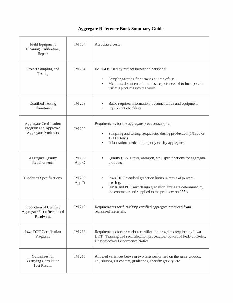
Aggregate Reference Book Summary Guide
Field Equipment
Cleaning, Calibration, Repair
IM 104
Associated costs
Project Sampling and
Testing
IM 204
IM 204 is used by project inspection personnel:
• Sampling/testing frequencies at time of use• Methods, documentation or test reports needed to incorporate
various products into the work
Qualified Testing
Laboratories
IM 208
• Basic required information, documentation and equipment• Equipment checklists
Aggregate CertificationProgram and ApprovedAggregate Producers
IM 209
Requirements for the aggregate producer/supplier:
• Sampling and testing frequencies during production (1/1500 or 1/3000 tons)
• Information needed to properly certify aggregates
Aggregate Quality
Requirements
IM 209App C
• Quality (F & T tests, abrasion, etc.) specifications for aggregate
products.
Gradation Specifications
IM 209App D
• Iowa DOT standard gradation limits in terms of percent
passing.• HMA and PCC mix design gradation limits are determined by
the contractor and supplied to the producer on 955’s.
Production of Certified
Aggregate From Reclaimed Roadways
IM 210
Requirements for furnishing certified aggregate produced from reclaimed materials.
Iowa DOT Certification
Programs
IM 213
Requirements for the various certification programs required by Iowa DOT. Training and recertification procedures: Iowa and Federal Codes; Unsatisfactory Performance Notice
Guidelines for
Verifying CorrelationTest Results
IM 216
Allowed variances between two tests performed on the same product, i.e., slumps, air content, gradations, specific gravity, etc.
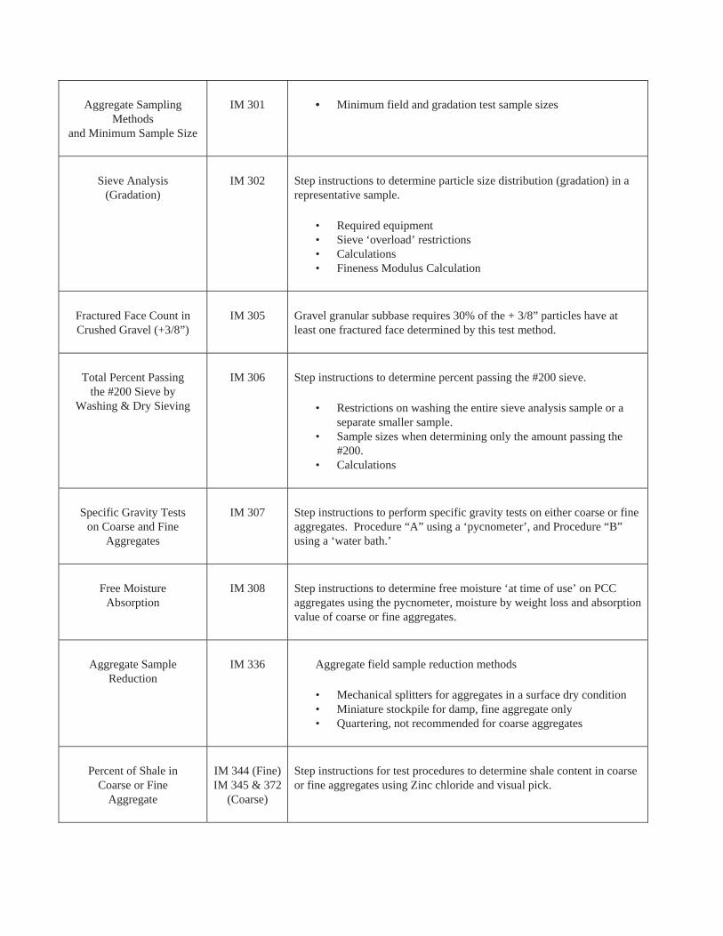
Aggregate Sampling Methods
and Minimum Sample Size
IM 301 • Minimum field and gradation test sample sizes
Sieve Analysis(Gradation)
IM 302 Step instructions to determine particle size distribution (gradation) in a representative sample.
• Required equipment• Sieve ‘overload’ restrictions• Calculations• Fineness Modulus Calculation
Fractured Face Count inCrushed Gravel (+3/8”)
IM 305 Gravel granular subbase requires 30% of the + 3/8” particles have at least one fractured face determined by this test method.
Total Percent Passingthe #200 Sieve by
Washing & Dry Sieving
IM 306 Step instructions to determine percent passing the #200 sieve.
• Restrictions on washing the entire sieve analysis sample or aseparate smaller sample.
• Sample sizes when determining only the amount passing the#200.
• Calculations
Specific Gravity Testson Coarse and Fine
Aggregates
IM 307 Step instructions to perform specific gravity tests on either coarse or fine aggregates. Procedure “A” using a ‘pycnometer’, and Procedure “B” using a ‘water bath.’
Free MoistureAbsorption
IM 308 Step instructions to determine free moisture ‘at time of use’ on PCC aggregates using the pycnometer, moisture by weight loss and absorption value of coarse or fine aggregates.
Aggregate SampleReduction
IM 336 Aggregate field sample reduction methods
• Mechanical splitters for aggregates in a surface dry condition• Miniature stockpile for damp, fine aggregate only• Quartering, not recommended for coarse aggregates
Percent of Shale inCoarse or Fine
Aggregate
IM 344 (Fine)IM 345 & 372
(Coarse)
Step instructions for test procedures to determine shale content in coarse or fine aggregates using Zinc chloride and visual pick.
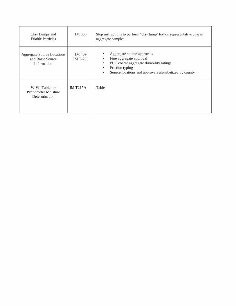
Clay Lumps and
Friable Particles
IM 368
Step instructions to perform „clay lump‟ test on representative coarse
aggregate samples.
Aggregate Source Locations
and Basic Source
Information
IM 409
IM T-203
• Aggregate source approvals
• Fine aggregate approval
• PCC coarse aggregate durability ratings
• Friction typing
• Source locations and approvals alphabetized by county
W-W1 Table for
Pycnometer Moisture
Determination
IM T215A
Table


Aggregate Reference Book Summary Guide
Field Equipment
Cleaning, Calibration, Repair
IM 104
Associated costs
Project Sampling and
Testing
IM 204
IM 204 is used by project inspection personnel:
• Sampling/testing frequencies at time of use• Methods, documentation or test reports needed to incorporate
various products into the work
Qualified Testing
Laboratories
IM 208
• Basic required information, documentation and equipment• Equipment checklists
Aggregate CertificationProgram and ApprovedAggregate Producers
IM 209
Requirements for the aggregate producer/supplier:
• Sampling and testing frequencies during production (1/1500 or 1/3000 tons)
• Information needed to properly certify aggregates
Aggregate Quality
Requirements
IM 209App C
• Quality (F & T tests, abrasion, etc.) specifications for aggregate
products.
Gradation Specifications
IM 209App D
• Iowa DOT standard gradation limits in terms of percent
passing.• HMA and PCC mix design gradation limits are determined by
the contractor and supplied to the producer on 955’s.
Production of Certified
Aggregate From Reclaimed Roadways
IM 210
Requirements for furnishing certified aggregate produced from reclaimed materials.
Iowa DOT Certification
Programs
IM 213
Requirements for the various certification programs required by Iowa DOT. Training and recertification procedures: Iowa and Federal Codes; Unsatisfactory Performance Notice
Guidelines for
Verifying CorrelationTest Results
IM 216
Allowed variances between two tests performed on the same product, i.e., slumps, air content, gradations, specific gravity, etc.

Aggregate Sampling
Methodsand Minimum Sample Size
IM 301
• Minimum field and gradation test sample sizes
Sieve Analysis
(Gradation)
IM 302
Step instructions to determine particle size distribution (gradation) in a representative sample.
• Required equipment• Sieve ‘overload’ restrictions• Calculations• Fineness Modulus Calculation
Fractured Face Count inCrushed Gravel (+3/8”)
IM 305
Gravel granular subbase requires 30% of the + 3/8” particles have at least one fractured face determined by this test method.
Total Percent Passing
the #200 Sieve byWashing & Dry Sieving
IM 306
Step instructions to determine percent passing the #200 sieve.
• Restrictions on washing the entire sieve analysis sample or a separate smaller sample.
• Sample sizes when determining only the amount passing the #200.
• Calculations
Specific Gravity Tests
on Coarse and FineAggregates
IM 307
Step instructions to perform specific gravity tests on either coarse or fine aggregates. Procedure “A” using a ‘pycnometer’, and Procedure “B” using a ‘water bath.’
Free Moisture
Absorption
IM 308
Step instructions to determine free moisture ‘at time of use’ on PCC aggregates using the pycnometer, moisture by weight loss and absorption value of coarse or fine aggregates.
Aggregate Sample
Reduction
IM 336
Aggregate field sample reduction methods
• Mechanical splitters for aggregates in a surface dry condition• Miniature stockpile for damp, fine aggregate only• Quartering, not recommended for coarse aggregates
Percent of Shale inCoarse or Fine
Aggregate
IM 344 (Fine)IM 345 & 372
(Coarse)
Step instructions for test procedures to determine shale content in coarse or fine aggregates using Zinc chloride and visual pick.

Clay Lumps and
Friable Particles
IM 368
Step instructions to perform „clay lump‟ test on representative coarse
aggregate samples.
Aggregate Source Locations
and Basic Source
Information
IM 409
IM T-203
• Aggregate source approvals
• Fine aggregate approval
• PCC coarse aggregate durability ratings
• Friction typing
• Source locations and approvals alphabetized by county
W-W1 Table for
Pycnometer Moisture
Determination
IM T215A
Table


SPEC 4109
A
GG
. GR
AD
. TAB
LE


Oct
ober
17,
201
7S
pec
4109
Sup
erse
des
Apr
il 18
, 201
7A
ggre
gate
Gra
datio
n T
able
AG
GR
EG
AT
E G
RA
DA
TIO
N T
AB
LE
Gra
d.
No
.S
ecti
on
No
.S
td. S
ieve
Sz.
1 1/2”
1.00”
3/4”
1/2”
3/8”
48
3050
100
200
Inte
nd
ed U
seP
erce
nt
Pas
sin
gN
ote
s
141
10,
4125
, 41
33, 4
134
PC
C F
A,
Cov
er A
gg.
100
90-
100
70-
100
10-
600-
1.5
1
241
12P
CC
Int
erm
edia
te95
-10
00-
10
341
15 (
57,
2-8)
, 41
18P
CC
CA
100
95-
100
25-6
00-
100-
50-
1.5
2, 1
0
441
15 (
2-8)
PC
C C
A10
050
-10
030
-10
020
-75
5-55
0-10
0-5
0-1.
510
541
15 (
67,
2-8)
PC
C C
A10
090
-10
020
-55
0-10
0-5
0-1.
510
641
15.0
6 (R
epai
r &
Ove
rlay)
PC
C C
A10
090
-10
040
-90
0-30
0-1.
510
741
17 (
Cla
ss V
)P
CC
FA
& C
A10
080
-92
60-7
520
-40
841
17.0
3 (C
lass
V)
Fin
e Li
mes
tone
100
90-
100
0-30
1041
19,
4120
.02,
412
0.03
(C
gra
vel)
Gra
nula
r S
urfa
ce10
050
-80
25-6
03,
11
1141
19,
4120
.02,
412
0.04
, 412
0.05
,41
20.0
7,(A
, B C
r. S
t.)
Gra
nula
r S
urfa
ce &
Sho
ulde
r10
095
-10
070
-90
30-5
515
-40
6-16
4, 5
,11
12a
4121
(C
r. S
t.)
Gra
nula
r S
ubba
se10
040
-80
5-25
0-6
6, 1
1
12b
4121
(C
r. G
rave
l)G
ranu
lar
Sub
base
100
50-8
010
-30
5-15
3-7
7, 1
1
1341
22.0
2 (C
r. S
t.)
Mac
adam
St.
Bas
e3”
nom
inal m
axim
um
siz
e s
cre
ened o
ver
3/4
” or
1.0
0”
scre
en.
1441
23M
odifi
ed S
ubba
se10
070
-90
10-4
03-
105,
7,
11
194125 (
1/2
”) C
r. G
r. o
r C
r. S
t.)
Cov
er A
ggre
gate
100
97-
100
40-9
00-
300-
150- 1.
511
204125 (
1/2
” S
cr.
Gr.
)C
over
Agg
rega
te10
095
-10
040
-80
0-15
0-7
0-1.
511
214125 (
3/8
”)C
over
Agg
rega
te10
090
-10
010
-55
0-20
0-7
0-1.
511
2241
24F
ine
Slu
rry
Mix
ture
100
85-
100
40-9
520
-60
14-
3510
-25
5-25
9, 1
1
2341
24 (
Cr.
St.
)C
oars
e S
lurr
y M
ixtu
re10
070
-90
40-7
019
-42
5-15
11
2941
31P
orou
s B
ackf
ill10
095
-10
050
-10
00-
500-
811
3041
32.0
2 (C
r. S
t.)
Spe
cial
Bac
kfill
100
10-4
00-
105,
11
3141
32.0
3 (G
rave
l)S
peci
al B
ackf
ill10
090
-10
075
-10
030
-55
3-7
11
3241
33 (
San
d/G
r./C
r. S
t.)G
ranu
lar
Bac
kfill
100%
passin
g t
he 3
” scre
en
10-
100
0-10
8, 1
1
3541
34 (
Nat
ural
San
d/G
r.)
Flo
odab
le B
ackf
ill10
020
-90
0-4
11
3641
34 (
Nat
ural
San
d)F
lood
able
Bac
kfill
100
0-2
11
37
2320
(Q
uart
zite
/Gra
nite
/Sla
g)
Pol
ymer
-Mod
ified
Mic
rosu
rfac
ing
100
90-1
00
65-9
0 30
-50
18-3
0 10
-21
5-15
12
, 13
38
2320
(lim
esto
ne/D
olom
ite)
Pol
ymer
-Mod
ified
Mic
rosu
rfac
ing
100
70-9
0 45
-70
15-3
5 10
-25
5-20
5-
15
12, 1
3
No
tes
: (
Gra
da
tio
ns
No
. 9,
15,
16
, 17
, 18
, 24
, 25
, 26
, 27
, 28
, 3
3, a
nd
34
ha
ve b
ee
n d
ele
ted
)

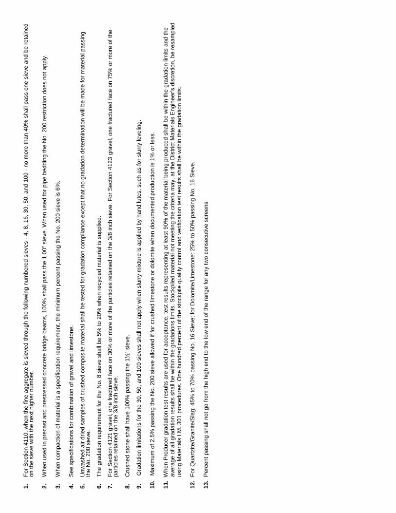
1.
Fo
r S
ect
ion
41
10,
wh
en
the
fin
e a
gg
reg
ate
is s
ieve
d t
hro
ugh
the
fol
low
ing
nu
mb
ere
d si
eve
s -
4,
8, 1
6, 3
0, 5
0, a
nd
10
0 -
no
mo
re t
han
40%
sh
all
pas
s on
e s
ieve
and
be
reta
ine
d o
n t
he
sie
ve w
ith t
he
ne
xt h
ighe
r n
umb
er.
2
. W
hen
use
d in
pre
cast
and
pre
stre
ssed
con
cre
te b
ridge
bea
ms,
10
0% s
hall
pas
s th
e 1
.00"
sie
ve. W
hen
use
d fo
r p
ipe
bed
din
g th
e N
o.
200
res
tric
tion
do
es
no
t ap
ply
. 3
. W
hen
com
pac
tion
of m
ate
rial
is a
sp
ecifi
catio
n re
qui
rem
en
t, th
e m
inim
um p
erc
ent
pas
sin
g th
e N
o.
200
sie
ve is
6%
. 4
. S
ee
spe
cific
atio
ns
for
com
bin
atio
n o
f g
rave
l and
lim
esto
ne.
5.
Unw
ash
ed
air
dri
ed s
am
ple
s of
cru
she
d co
mpo
site
ma
teria
l sh
all
be
test
ed
fo
r g
rada
tion
com
plia
nce
exc
ep
t th
at n
o g
rad
atio
n d
ete
rmin
atio
n w
ill b
e m
ade
fo
r m
ate
rial p
assi
ng
th
e N
o. 2
00
sie
ve.
6.
Th
e g
rad
atio
n r
eq
uire
me
nt
for
the
No
. 8 s
ieve
sh
all
be
5%
to 2
0%
wh
en
rec
ycle
d m
ate
rial i
s su
pplie
d.
7.
Fo
r S
ect
ion
41
21 g
rave
l, on
e fr
act
ure
d f
ace
on
30
% o
r m
ore
of
the
pa
rtic
les
reta
ine
d o
n th
e 3
/8 in
ch s
ieve
. F
or
Se
ctio
n 4
123
gra
vel,
one
fra
ctu
red
fac
e o
n 7
5%
or
mo
re o
f th
e
pa
rtic
les
reta
ine
d o
n t
he
3/8
inch
sie
ve.
8.
Cru
she
d st
on
e s
hal
l ha
ve 1
00%
pas
sin
g t
he
1½
” si
eve
. 9
. G
rad
atio
n li
mita
tion
s fo
r th
e 3
0, 5
0,
and
10
0 s
ieve
s sh
all
no
t ap
ply
wh
en
slu
rry
mix
ture
is a
pp
lied
by
han
d lu
tes,
su
ch a
s fo
r sl
urr
y le
velin
g.
10
. M
axi
mu
m o
f 2
.5%
pa
ssin
g th
e N
o.
20
0 si
eve
allo
we
d if
for
cru
shed
lim
esto
ne
or
do
lom
ite w
he
n d
ocu
me
nte
d p
rodu
ctio
n is
1%
or
less
. 1
1.
Whe
n P
rod
uce
r g
rad
atio
n te
st r
esu
lts a
re u
sed
fo
r a
cce
pta
nce
, te
st r
esul
ts r
ep
rese
ntin
g a
t le
ast
90%
of t
he
ma
teri
al b
ein
g p
rod
uce
d s
ha
ll be
with
in t
he
gra
da
tion
lim
its a
nd t
he
ave
rag
e o
f a
ll g
rad
atio
n r
esu
lts s
hall
be
with
in t
he
gra
datio
ns li
mits
. S
tock
pile
d m
ate
ria
l not
me
etin
g th
e cr
iteri
a m
ay,
at
the
Dis
tric
t M
ate
ria
ls E
ngin
ee
r’s d
iscre
tion
, be
resa
mp
led
u
sing
Ma
teri
als
I.M
. 3
01
pro
ced
ure
s. O
ne
hu
nd
red
pe
rce
nt
of t
he
sto
ckpi
le q
ual
ity c
on
trol
an
d v
eri
fica
tion
test
re
sults
sh
all
be
with
in th
e g
rad
atio
n lim
its.
12
. F
or
Qua
rtzi
te/G
ran
ite/S
lag
: 4
5% t
o 7
0%
pa
ssin
g N
o.
16 S
ieve
; fo
r D
olo
mite
/Lim
est
on
e: 2
5% t
o 5
0%
pa
ssin
g N
o.
16 S
ieve
. 1
3.
Pe
rce
nt p
assi
ng
sh
all n
ot
go f
rom
the
hig
h e
nd
to t
he lo
w e
nd o
f th
e r
ang
e fo
r a
ny
two
con
secu
tive
scr
een
s

Oct
ober
17,
201
7
S
pec
4109
S
uper
sede
s A
pril
18, 2
017
A
ggre
gate
Gra
datio
n T
able
AG
GR
EG
AT
E G
RA
DA
TIO
N T
AB
LE
G
rad
. N
o.
Sec
tio
n N
o.
Std
. Sie
ve S
z.
1 1/2”
1.00”
3/4”
1/2”
3/8”
4 8
30
50
100
200
In
ten
ded
Use
P
erce
nt
Pas
sin
g
No
tes
1 41
10,
4125
, 41
33, 4
134
PC
C F
A,
Cov
er A
gg.
100
90-
100
70-
100
10-
60
0-1.
5 1
2 41
12
PC
C I
nter
med
iate
95-
100
0-10
3 41
15 (
57,
2-8)
, 41
18
PC
C C
A
100
95-
100
25
-60
0-10
0-
5
0-1.
5 2,
10
4 41
15 (
2-8)
P
CC
CA
10
0 50
-10
0 30
-10
0 20
-75
5-
55
0-10
0-
5
0-1.
5 10
5 41
15 (
67,
2-8)
P
CC
CA
100
90-
100
20
-55
0-
10
0-5
0-
1.5
10
6 41
15.0
6 (R
epai
r &
Ove
rlay)
P
CC
CA
10
0 90
-10
0 40
-90
0-
30
0-1.
5 10
7 41
17 (
Cla
ss V
) P
CC
FA
& C
A
100
80-9
2
60-7
5
20-
40
8 41
17.0
3 (C
lass
V)
Fin
e Li
mes
tone
10
0 90
-10
0
0-
30
10
4119
, 41
20.0
2, 4
120.
03 (
C g
rave
l)
Gra
nula
r S
urfa
ce
100
50-8
0
25-6
0
3, 1
1
11
4119
, 41
20.0
2, 4
120.
04, 4
120.
05,
4120
.07,
(A
, B C
r. S
t.)
Gra
nula
r S
urfa
ce &
S
houl
der
10
0 95
-10
0 70
-90
30-5
5
15-4
0
6-
16
4, 5
, 11
12a
4121
(C
r. S
t.)
Gra
nula
r S
ubba
se
100
40-8
0
5-25
0-6
6, 1
1
12b
4121
(C
r. G
rave
l) G
ranu
lar
Sub
base
10
0
50
-80
10
-30
5-15
3-7
7, 1
1
13
4122
.02
(Cr.
St.
) M
acad
am S
t. B
ase
3”
nom
inal m
axim
um
siz
e s
cre
ened o
ver
3/4
” or
1.0
0”
scre
en.
14
4123
M
odifi
ed S
ubba
se
100
70
-90
10-4
0
3-
10
5, 7
, 11
19
4125 (
1/2
”) C
r. G
r. o
r C
r. S
t.)
Cov
er A
ggre
gate
10
0 97
-10
0 40
-90
0-
30
0-15
0-
1.5
11
20
4125 (
1/2
” S
cr.
Gr.
) C
over
Agg
rega
te
100
95-
100
40-8
0
0-15
0-
7
0-1.
5 11
21
4125 (
3/8
”)
Cov
er A
ggre
gate
100
90-
100
10-5
5
0-20
0-
7
0-
1.5
11
22
4124
F
ine
Slu
rry
Mix
ture
10
0 85
-10
0 40
-95
20
-60
14
-35
10
-25
5-
25
9, 1
1
23
4124
(C
r. S
t.)
Coa
rse
Slu
rry
Mix
ture
10
0 70
-90
40
-70
19
-42
5-
15
11
29
4131
P
orou
s B
ackf
ill
100
95-
100
50-
100
0-50
0-
8
11
30
4132
.02
(Cr.
St.
) S
peci
al B
ackf
ill
100
10
-40
0-10
5,
11
31
4132
.03
(Gra
vel)
Spe
cial
Bac
kfill
100
90-
100
75-
100
30-5
5
3-
7 11
32
4133
(S
and/
Gr.
/Cr.
St.)
G
ranu
lar
Bac
kfill
100%
passin
g t
he 3
” scre
en
10-
100
0-
10
8, 1
1
35
4134
(N
atur
al S
and/
Gr.
) F
lood
able
Bac
kfill
10
0
20-9
0
0-
4 11
36
4134
(N
atur
al S
and)
F
lood
able
Bac
kfill
100
0-2
11
37
2320
(Q
uart
zite
/Gra
nite
/Sla
g)
Pol
ymer
-Mod
ified
Mic
rosu
rfac
ing
100
90-1
00
65-9
0 30
-50
18-3
0 10
-21
5-15
12
, 13
38
2320
(lim
esto
ne/D
olom
ite)
Pol
ymer
-Mod
ified
Mic
rosu
rfac
ing
100
70-9
0 45
-70
15-3
5 10
-25
5-20
5-
15
12, 1
3
No
tes
: (
Gra
da
tio
ns
No
. 9,
15,
16
, 17
, 18
, 24
, 25
, 26
, 27
, 28
, 3
3, a
nd
34
ha
ve b
ee
n d
ele
ted
)
1.
Fo
r S
ect
ion
41
10,
wh
en
the
fin
e a
gg
reg
ate
is s
ieve
d t
hro
ugh
the
fol
low
ing
nu
mb
ere
d si
eve
s -
4,
8, 1
6, 3
0, 5
0, a
nd
10
0 -
no
mo
re t
han
40%
sh
all
pas
s on
e s
ieve
and
be
reta
ine
d o
n t
he
sie
ve w
ith t
he
ne
xt h
ighe
r n
umb
er.
2
. W
hen
use
d in
pre
cast
and
pre
stre
ssed
con
cre
te b
ridge
bea
ms,
10
0% s
hall
pas
s th
e 1
.00"
sie
ve. W
hen
use
d fo
r p
ipe
bed
din
g th
e N
o.
200
res
tric
tion
do
es
no
t ap
ply
. 3
. W
hen
com
pac
tion
of m
ate
rial
is a
sp
ecifi
catio
n re
qui
rem
en
t, th
e m
inim
um p
erc
ent
pas
sin
g th
e N
o.
200
sie
ve is
6%
. 4
. S
ee
spe
cific
atio
ns
for
com
bin
atio
n o
f g
rave
l and
lim
esto
ne.
5.
Unw
ash
ed
air
dri
ed s
am
ple
s of
cru
she
d co
mpo
site
ma
teria
l sh
all
be
test
ed
fo
r g
rada
tion
com
plia
nce
exc
ep
t th
at n
o g
rad
atio
n d
ete
rmin
atio
n w
ill b
e m
ade
fo
r m
ate
rial p
assi
ng
th
e N
o. 2
00
sie
ve.
6.
Th
e g
rad
atio
n r
eq
uire
me
nt
for
the
No
. 8 s
ieve
sh
all
be
5%
to 2
0%
wh
en
rec
ycle
d m
ate
rial i
s su
pplie
d.
7.
Fo
r S
ect
ion
41
21 g
rave
l, on
e fr
act
ure
d f
ace
on
30
% o
r m
ore
of
the
pa
rtic
les
reta
ine
d o
n th
e 3
/8 in
ch s
ieve
. F
or
Se
ctio
n 4
123
gra
vel,
one
fra
ctu
red
fac
e o
n 7
5%
or
mo
re o
f th
e
pa
rtic
les
reta
ine
d o
n t
he
3/8
inch
sie
ve.
8.
Cru
she
d st
on
e s
hal
l ha
ve 1
00%
pas
sin
g t
he
1½
” si
eve
. 9
. G
rad
atio
n li
mita
tion
s fo
r th
e 3
0, 5
0,
and
10
0 s
ieve
s sh
all
no
t ap
ply
wh
en
slu
rry
mix
ture
is a
pp
lied
by
han
d lu
tes,
su
ch a
s fo
r sl
urr
y le
velin
g.
10
. M
axi
mu
m o
f 2
.5%
pa
ssin
g th
e N
o.
20
0 si
eve
allo
we
d if
for
cru
shed
lim
esto
ne
or
do
lom
ite w
he
n d
ocu
me
nte
d p
rodu
ctio
n is
1%
or
less
. 1
1.
Whe
n P
rod
uce
r g
rad
atio
n te
st r
esu
lts a
re u
sed
fo
r a
cce
pta
nce
, te
st r
esul
ts r
ep
rese
ntin
g a
t le
ast
90%
of t
he
ma
teri
al b
ein
g p
rod
uce
d s
ha
ll be
with
in t
he
gra
da
tion
lim
its a
nd t
he
ave
rag
e o
f a
ll g
rad
atio
n r
esu
lts s
hall
be
with
in t
he
gra
datio
ns li
mits
. S
tock
pile
d m
ate
ria
l not
me
etin
g th
e cr
iteri
a m
ay,
at
the
Dis
tric
t M
ate
ria
ls E
ngin
ee
r’s d
iscre
tion
, be
resa
mp
led
u
sing
Ma
teri
als
I.M
. 3
01
pro
ced
ure
s. O
ne
hu
nd
red
pe
rce
nt
of t
he
sto
ckpi
le q
ual
ity c
on
trol
an
d v
eri
fica
tion
test
re
sults
sh
all
be
with
in th
e g
rad
atio
n lim
its.
12
. F
or
Qua
rtzi
te/G
ran
ite/S
lag
: 4
5% t
o 7
0%
pa
ssin
g N
o.
16 S
ieve
; fo
r D
olo
mite
/Lim
est
on
e: 2
5% t
o 5
0%
pa
ssin
g N
o.
16 S
ieve
. 1
3.
Pe
rce
nt p
assi
ng
sh
all n
ot
go f
rom
the
hig
h e
nd
to t
he lo
w e
nd o
f th
e r
ang
e fo
r a
ny
two
con
secu
tive
scr
een
s

IM 204
SA
MP
LIN
G &
TE
ST
ING
.


October 17, 2017 Matls. IM 204 Supersedes October 18, 2016
1
Office of Construction & Materials
INSPECTION OF CONSTRUCTION PROJECT SAMPLING & TESTING
INTRODUCTION The Iowa Department of Transportation (DOT) has established a Quality Assurance Program (IM 205) to assure that the quality of materials and construction workmanship incorporated into all highway construction projects is in reasonable conformity with the requirements of the approved plans and Specifications, including approved changes. It consists of an Acceptance Program and an Independent Assurance Program (IAP), both of which are based on test results obtained by qualified persons and equipment. The acceptance portion of the program covers quality control (QC) sampling and testing and verification sampling and testing. The IAP portion of the program covers the evaluation of all sampling and testing procedures, personnel, and equipment used as part of an acceptance decision (includes contractor, contracting agency, and consultant). ACCEPTANCE PROGRAM FOR MATERIALS To fulfill the materials acceptance requirements, several methods are used by the DOT. Sampling & Testing (Test Report) Certification Approved Brands Approved Sources Approved Shop Drawings Approved Catalog Cut Inspection Report Visual Approval by the Engineer The Instructional Memorandum IM 204 Appendices A through W contain the material acceptance information for the type of work being done. If there is a conflict in wording between the appendix and another Instructional Memorandum or appendix Z, the appendix A through W will supersede the others. In many cases more than one method may be required for acceptance in the 204 Appendices and tables in the back of this guide. For some new or special materials, the District Materials Engineer may need to determine the most appropriate acceptance requirements. In order to provide the Contractor the opportunity to construct a project with minimal sampling and testing delays, inspection is performed at the source for many materials. Source inspection may consist of inspecting process control, sampling for laboratory testing or a combination of these procedures. All source-inspected or certified materials are subject to inspection at the project site prior to being incorporated into the work. Project site inspections are for identification of materials with test reports and for any unusual alterations of the characteristics of the material due to handling or other causes. Verification samples secured by project agency personnel of source-inspected, certified, or project processed materials are also required for some materials in order to secure satisfactory validation for acceptance.
October 17, 2017 Matls. IM 204 Supersedes October 18, 2016
2
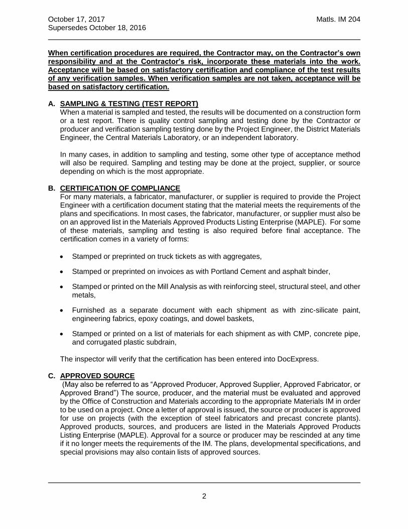
When certification procedures are required, the Contractor may, on the Contractor’s own responsibility and at the Contractor’s risk, incorporate these materials into the work. Acceptance will be based on satisfactory certification and compliance of the test results of any verification samples. When verification samples are not taken, acceptance will be based on satisfactory certification. A. SAMPLING & TESTING (TEST REPORT)
When a material is sampled and tested, the results will be documented on a construction form or a test report. There is quality control sampling and testing done by the Contractor or producer and verification sampling testing done by the Project Engineer, the District Materials Engineer, the Central Materials Laboratory, or an independent laboratory.
In many cases, in addition to sampling and testing, some other type of acceptance method will also be required. Sampling and testing may be done at the project, supplier, or source depending on which is the most appropriate.
B. CERTIFICATION OF COMPLIANCE
For many materials, a fabricator, manufacturer, or supplier is required to provide the Project Engineer with a certification document stating that the material meets the requirements of the plans and specifications. In most cases, the fabricator, manufacturer, or supplier must also be on an approved list in the Materials Approved Products Listing Enterprise (MAPLE). For some of these materials, sampling and testing is also required before final acceptance. The certification comes in a variety of forms:
Stamped or preprinted on truck tickets as with aggregates,
Stamped or preprinted on invoices as with Portland Cement and asphalt binder,
Stamped or printed on the Mill Analysis as with reinforcing steel, structural steel, and other metals,
Furnished as a separate document with each shipment as with zinc-silicate paint, engineering fabrics, epoxy coatings, and dowel baskets,
Stamped or printed on a list of materials for each shipment as with CMP, concrete pipe, and corrugated plastic subdrain,
The inspector will verify that the certification has been entered into DocExpress.
C. APPROVED SOURCE
(May also be referred to as “Approved Producer, Approved Supplier, Approved Fabricator, or Approved Brand”) The source, producer, and the material must be evaluated and approved by the Office of Construction and Materials according to the appropriate Materials IM in order to be used on a project. Once a letter of approval is issued, the source or producer is approved for use on projects (with the exception of steel fabricators and precast concrete plants). Approved products, sources, and producers are listed in the Materials Approved Products Listing Enterprise (MAPLE). Approval for a source or producer may be rescinded at any time if it no longer meets the requirements of the IM. The plans, developmental specifications, and special provisions may also contain lists of approved sources.

October 17, 2017 Matls. IM 204 Supersedes October 18, 2016
3
The project inspector will document information about this material such as product name, source, date, producer, and lot number in the project files.
Most approved sources also require a certification.
D. APPROVED WAREHOUSE STOCK
For some items made up of miscellaneous materials, inspection and approval will be done by the District Materials Engineer at the supplier’s warehouse.
E. APPROVED SHOP DRAWING & APPROVED CATALOG CUT
This information must be submitted to, and reviewed by the Iowa DOT Design Office or Bridges and Structures Office, before the material can be incorporated in the project.
F. INSPECTION REPORT
The project inspector must have a copy of the final inspection report prior to incorporating the item into the project. The report will vary depending on the Materials IM requirements for the item fabricated. Final acceptance is by construction personnel at the project site, and is based on the proper documentation and the condition of the component.
G. VISUAL APPROVAL BY PROJECT ENGINEER
(May also be referred to as “As Per Plan, Approved By RCE, or Manufacturer Recommendations”) The project inspector must document information about this material such as product name, source, producer, lot number and date produced in the project files. The inspector will make sure the material meets the requirements of the plans, the Engineer, or the manufacturer before the material is used. Visual approval requires construction personnel to visually inspect the material to determine if it complies with the specifications. Visual approval is appropriate for non-critical items such as sod stakes, where compliance can be readily determined by visual means. If there are questions on specification compliance, samples will be taken for testing.
INDEPENDENT ASSURANCE PROGRAM The IAP evaluates all sampling and testing procedures, personnel, and equipment used as part of an acceptance decision (Includes Contractor, Contracting Agency, and consultant). Independent assurance includes evaluation based on: Calibration checks Split samples Proficiency samples Observation of sampling and testing performance The test method and the frequency of test are in the Appendices. Calibration checks and proficiency samples testing is covered in IM 208. SMALL QUANTITIES The FHWA allows and encourages alternative acceptance methods for small quantities of non-critical materials. Appendix X contains a list of those materials and maximum quantities for which alternative acceptance methods may be appropriate. The Project Engineer or District Materials Engineer may still require the normal acceptance method for a material when it is considered critical in the intended application.
October 17, 2017 Matls. IM 204 Supersedes October 18, 2016
4
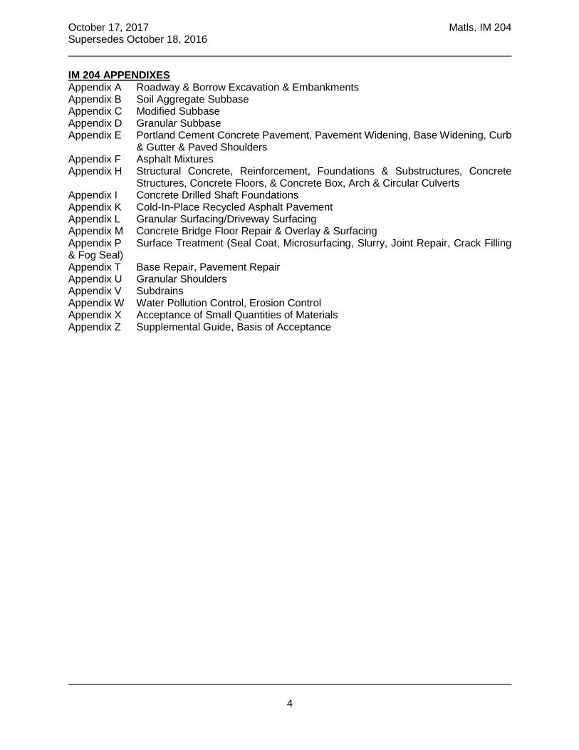
IM 204 APPENDIXES Appendix A Roadway & Borrow Excavation & Embankments Appendix B Soil Aggregate Subbase Appendix C Modified Subbase Appendix D Granular Subbase Appendix E Portland Cement Concrete Pavement, Pavement Widening, Base Widening, Curb
& Gutter & Paved Shoulders Appendix F Asphalt Mixtures Appendix H Structural Concrete, Reinforcement, Foundations & Substructures, Concrete
Structures, Concrete Floors, & Concrete Box, Arch & Circular Culverts Appendix I Concrete Drilled Shaft Foundations Appendix K Cold-In-Place Recycled Asphalt Pavement Appendix L Granular Surfacing/Driveway Surfacing Appendix M Concrete Bridge Floor Repair & Overlay & Surfacing Appendix P Surface Treatment (Seal Coat, Microsurfacing, Slurry, Joint Repair, Crack Filling & Fog Seal) Appendix T Base Repair, Pavement Repair Appendix U Granular Shoulders Appendix V Subdrains Appendix W Water Pollution Control, Erosion Control Appendix X Acceptance of Small Quantities of Materials Appendix Z Supplemental Guide, Basis of Acceptance
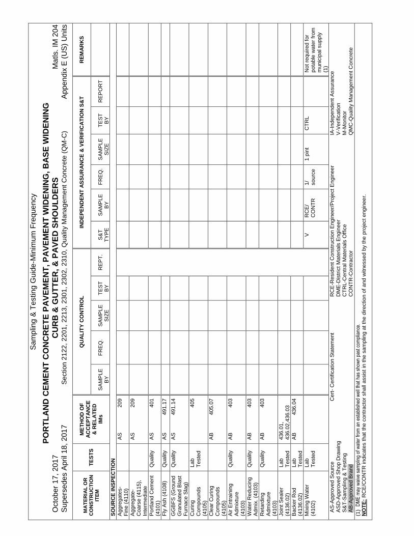
Sam
plin
g &
Tes
ting
Gui
de-M
inim
um F
req
uenc
y
PO
RT
LA
ND
CE
ME
NT
CO
NC
RE
TE
PA
VE
ME
NT
, P
AV
EM
EN
T W
IDE
NIN
G,
BA
SE
WID
EN
ING
O
ctob
er 1
7, 2
017
CU
RB
& G
UT
TE
R,
& P
AV
ED
SH
OU
LD
ER
S
Mat
ls.
IM 2
04
Sup
erse
des
Apr
il 18
, 201
7 S
ectio
n 2
122,
220
1, 2
213
, 23
01, 2
302
, 23
10,
Qu
ality
Man
age
men
t Con
cret
e (Q
M-C
) A
ppen
dix
E (
US
) U
nits
MA
TE
RIA
L O
R
CO
NS
TR
UC
TIO
N
ITE
M
TE
ST
S
ME
TH
OD
OF
A
CC
EP
TA
NC
E
& R
EL
AT
ED
IM
s
QU
AL
ITY
CO
NT
RO
L
IND
EP
EN
DE
NT
AS
SU
RA
NC
E &
VE
RIF
ICA
TIO
N S
&T
R
EM
AR
KS
S
AM
PLE
B
Y
F
RE
Q.
S
AM
PLE
S
IZE
T
ES
T
BY
R
EP
T.
S
&T
T
YP
E
S
AM
PLE
B
Y
F
RE
Q.
S
AM
PLE
S
IZE
T
ES
T
BY
R
EP
OR
T
SO
UR
CE
INS
PE
CT
ION
A
ggre
gate
s-
Fin
e (4
110)
AS
20
9
Agg
rega
te-
Coa
rse
(411
5),
Inte
rmed
iate
A
S
209
Por
tland
Cem
ent
(410
1)
Qua
lity
AS
40
1
Fly
Ash
(41
08)
Qua
lity
AS
49
1.17
GG
BF
S (
Gro
und
Gra
nula
ted
Bla
st
Fur
nace
Sla
g)
Qua
lity
AS
49
1.14
Cur
ing
Com
poun
ds
(410
5)
Lab
Tes
ted
40
5
Cle
ar C
urin
g C
ompo
unds
(4
105)
A
B
405.
07
Air
Ent
rain
ing
Adm
ixtu
re
(410
3)
Qua
lity
AB
40
3
Wat
er R
educ
ing
Adm
ix.
(410
3)
Qua
lity
AB
40
3
Ret
ardi
ng
Adm
ixtu
re
(410
3)
Qua
lity
AB
40
3
Join
t Sea
ler
(413
6.02
) La
b T
este
d 43
6.01
, 43
6.02
,436
.03
Bac
ker
Rod
(4
136.
02)
Lab
Tes
ted
AB
43
6.04
Mix
ing
Wat
er
(410
2)
Lab
Tes
ted
V
R
CE
/ C
ON
TR
1/
so
urce
1
pint
C
TR
L
Not
req
uire
d fo
r po
tabl
e w
ater
fro
m
mun
icip
al s
uppl
y (1
) A
S-A
ppro
ved
Sou
rce
Cer
t- C
ertif
icat
ion
Sta
tem
ent
RC
E-R
esid
ent
Con
stru
ctio
n E
ngin
eer/
Pro
ject
Eng
inee
r IA
-Ind
epen
dent
Ass
uran
ce
AS
D-A
ppro
ved
Sho
p D
raw
ing
DM
E-D
istr
ict
Mat
eria
ls E
ngin
eer
V-V
erifi
catio
n S
&T
-Sam
plin
g &
Tes
ting
C
TR
L-C
entr
al M
ater
ials
Offi
ce
M-M
onito
r A
B-A
ppro
ved
Bra
nd
C
ON
TR
-Con
trac
tor
QM
C-Q
ualit
y M
anag
emen
t Con
cret
e
(1)
DM
E m
ay w
aive
sam
plin
g of
wat
er fr
om a
n es
tabl
ishe
d w
ell t
hat h
as s
how
n pa
st c
ompl
ianc
e.
NO
TE
: R
CE
/CO
NT
R in
dica
tes
that
the
con
trac
tor
shal
l ass
ist
in t
he s
ampl
ing
at t
he d
irect
ion
of a
nd w
itnes
sed
by t
he p
roje
ct e
ngin
eer.

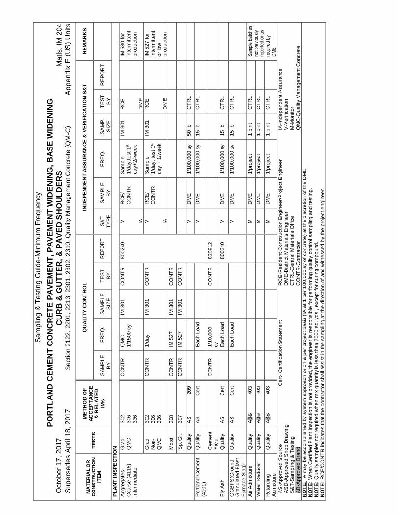
Sam
plin
g &
Tes
ting
Gui
de-M
inim
um F
req
uenc
y
PO
RT
LA
ND
CE
ME
NT
CO
NC
RE
TE
PA
VE
ME
NT
, P
AV
EM
EN
T W
IDE
NIN
G,
BA
SE
WID
EN
ING
O
ctob
er 1
7, 2
017
CU
RB
& G
UT
TE
R,
& P
AV
ED
SH
OU
LD
ER
S
Mat
ls.
IM 2
04
Sup
erse
des
Apr
il 18
, 201
7 S
ectio
n 2
122,
220
1, 2
213
, 23
01, 2
302
, 23
10,
Qu
ality
Man
age
men
t Con
cret
e (Q
M-C
) A
ppen
dix
E (
US
) U
nits
MA
TE
RIA
L O
R
CO
NS
TR
UC
TIO
N
ITE
M
TE
ST
S
ME
TH
OD
OF
A
CC
EP
TA
NC
E
& R
EL
AT
ED
IM
s
QU
AL
ITY
CO
NT
RO
L
IND
EP
EN
DE
NT
AS
SU
RA
NC
E &
VE
RIF
ICA
TIO
N S
&T
R
EM
AR
KS
S
AM
PLE
B
Y
F
RE
Q.
S
AM
PLE
S
IZE
T
ES
T
BY
R
EP
OR
T
S
&T
T
YP
E
S
AM
PLE
B
Y
F
RE
Q.
S
AM
PLE
S
IZE
T
ES
T
BY
R
EP
OR
T
SO
UR
CE
INS
PE
CT
ION
S
teel
R
einf
orce
men
t (4
151)
Dow
els
Qua
lity
A
S
451
Tie
Bar
s Q
ualit
y A
S
451
Gen
eral
Use
Q
ualit
y A
S
451
PL
AN
T I
NS
PE
CT
ION
A
ggre
gate
s-F
ine
(411
0/41
11)
Gra
d
QM
C
302
306
336
CO
NT
R
1/15
00cy
IM
301
C
ON
TR
80
0240
V
IA
RC
E/
CO
NT
R
Sam
ple
1/
day,
tes
t 1st
day
+
2/w
eek
IM 3
01
RC
E
DM
E
IM
530
for
in
term
itten
t pr
oduc
tion
G
rad
N
on-Q
MC
30
2 30
6 33
6
CO
NT
R
1/da
y IM
301
C
ON
TR
V
IA
RC
E/
CO
NT
R
Sam
ple
1/da
y, t
est
1st d
ay +
1/
wee
k
IM 3
01
RC
E
DM
E
IM
527
for
in
term
itten
t or
low
pr
oduc
tion
M
oist
30
8, 5
27
CO
NT
R
IM 5
27
1000
gm
C
ON
TR
N
ot
appl
icab
le
with
pro
be
S
p. G
r.
307
CO
NT
R
IM 5
27
1000
gm
C
ON
TR
Q
ualit
y A
S
209
AS
-App
rove
d S
ourc
e C
ert-
Cer
tific
atio
n S
tate
men
t R
CE
-Res
iden
t C
onst
ruct
ion
Eng
inee
r/P
roje
ct E
ngin
eer
IA-I
ndep
ende
nt A
ssur
ance
A
SD
-App
rove
d S
hop
Dra
win
g
D
ME
-Dis
tric
t M
ater
ials
Eng
inee
r V
-Ver
ifica
tion
S&
T-S
ampl
ing
& T
estin
g
CT
RL-
Cen
tral
Mat
eria
ls O
ffice
M
-Mon
itor
CO
NT
R-C
ontr
acto
r Q
MC
-Qua
lity
Man
agem
ent C
oncr
ete
NO
TE
: IA
may
be
acco
mpl
ishe
d by
sys
tem
app
roac
h or
on
a pe
r pr
ojec
t bas
is (
IA a
t 1 p
er 1
00,0
00 s
y of
con
cret
e) a
t the
dis
cret
ion
of th
e D
ME
. N
OT
E:
Whe
n C
ertif
ied
Pla
nt In
spec
tion
is n
ot p
rovi
ded,
the
eng
inee
r is
res
pons
ible
for
per
form
ing
qual
ity c
ontr
ol s
ampl
ing
and
test
ing.
N
OT
E:
RC
E/C
ON
TR
indi
cate
s th
at t
he c
ontr
acto
r sh
all a
ssis
t in
the
sam
plin
g at
the
dire
ctio
n of
and
witn
esse
d by
the
pro
ject
eng
inee
r.
Sam
plin
g &
Tes
ting
Gui
de-M
inim
um F
req
uenc
y
PO
RT
LA
ND
CE
ME
NT
CO
NC
RE
TE
PA
VE
ME
NT
, P
AV
EM
EN
T W
IDE
NIN
G,
BA
SE
WID
EN
ING
O
ctob
er 1
7, 2
017
CU
RB
& G
UT
TE
R,
& P
AV
ED
SH
OU
LD
ER
S
Mat
ls.
IM 2
04
Sup
erse
des
Apr
il 18
, 201
7 S
ectio
n 2
122,
220
1, 2
213
, 23
01, 2
302
, 23
10,
Qu
ality
Man
age
men
t Con
cret
e (Q
M-C
) A
ppen
dix
E (
US
) U
nits
MA
TE
RIA
L O
R
CO
NS
TR
UC
TIO
N
ITE
M
TE
ST
S
ME
TH
OD
OF
A
CC
EP
TA
NC
E
& R
EL
AT
ED
IM
s
QU
AL
ITY
CO
NT
RO
L
IND
EP
EN
DE
NT
AS
SU
RA
NC
E &
VE
RIF
ICA
TIO
N S
&T
R
EM
AR
KS
S
AM
PLE
B
Y
F
RE
Q.
S
AM
PLE
S
IZE
T
ES
T
BY
R
EP
OR
T
S
&T
T
YP
E
S
AM
PLE
B
Y
F
RE
Q.
S
AM
P.
SIZ
E
T
ES
T
BY
R
EP
OR
T
PL
AN
T I
NS
PE
CT
ION
Agg
rega
tes-
C
oars
e (4
115)
, In
term
edia
te
Gra
d
QM
C
302
306
336
CO
NT
R
QM
C
1/15
00 c
y IM
301
C
ON
TR
80
0240
V
IA
RC
E/
CO
NT
R
Sam
ple
1/da
y,te
st 1
st
day+
2/ w
eek
IM 3
01
R
CE
D
ME
IM 5
30 f
or
inte
rmitt
ent
prod
uctio
n
G
rad
N
on-
QM
C
302
306
336
CO
NT
R
1/da
y IM
301
C
ON
TR
V
IA
RC
E/
CO
NT
R
Sam
ple
1/da
y, t
est 1
st
day
+ 1
/wee
k
IM 3
01
R
CE
D
ME
IM
527
for
in
term
itten
t or
low
pr
oduc
tion
M
oist
30
8 C
ON
TR
IM
527
IM
301
C
ON
TR
S
p. G
r.
307
CO
NT
R
IM 5
27
IM 3
01
CO
NT
R
Q
ualit
y A
S
209
V
DM
E
1/10
0,00
0 sy
50
lb
CT
RL
Por
tland
Cem
ent
(410
1)
Qua
lity
AS
C
ert
E
ach
Load
V
D
ME
1/
100,
000
sy
15 lb
C
TR
L
C
emen
t Y
ield
C
ON
TR
1/
10,0
00
cy
C
ON
TR
82
0912
Fly
Ash
Q
ualit
y A
S
Cer
t
Eac
h Lo
ad
8002
40
V
DM
E
1/10
0,00
0 sy
15
lb
CT
RL
GG
BF
S(G
roun
d G
ranu
late
d B
last
F
urna
ce S
lag)
Qua
lity
AS
C
ert
E
ach
Load
V
D
ME
1/
100,
000
sy
15 lb
C
TR
L
Air
Adm
ixtu
re
Qua
lity
AB
S
403
M
D
ME
1/
proj
ect
1 pi
nt
CT
RL
S
ampl
e ba
tche
s no
t pre
viou
sly
repo
rted
or
as
requ
ired
by
DM
E
Wat
er R
educ
er
Qua
lity
AB
S
403
M
D
ME
1/
proj
ect
1 pi
nt
CT
RL
Ret
ardi
ng
Adm
ixtu
re
Qua
lity
AB
S
403
M
D
ME
1/
proj
ect
1 pi
nt
CT
RL
AS
-App
rove
d S
ourc
e C
ert-
Cer
tific
atio
n S
tate
men
t R
CE
-Res
iden
t C
onst
ruct
ion
Eng
inee
r/P
roje
ct E
ngin
eer
IA-I
ndep
ende
nt A
ssur
ance
A
SD
-App
rove
d S
hop
Dra
win
g
D
ME
-Dis
tric
t M
ater
ials
Eng
inee
r V
-Ver
ifica
tion
S&
T-S
ampl
ing
& T
estin
g
CT
RL-
Cen
tral
Mat
eria
ls O
ffice
M
-Mon
itor
AB
-App
rove
d B
rand
CO
NT
R-C
ontr
acto
r Q
MC
-Qua
lity
Man
agem
ent C
oncr
ete
NO
TE
: IA
may
be
acco
mpl
ishe
d by
sys
tem
app
roac
h or
on
a pe
r pr
ojec
t bas
is (
IA a
t 1 p
er 1
00,0
00 s
y of
con
cret
e) a
t the
dis
cret
ion
of th
e D
ME
. N
OT
E:
Whe
n C
ertif
ied
Pla
nt In
spec
tion
is n
ot p
rovi
ded,
the
eng
inee
r is
res
pons
ible
for
per
form
ing
qual
ity c
ontr
ol s
ampl
ing
and
test
ing.
N
OT
E:
Qua
lity
sam
ples
not
req
uire
d w
hen
mix
qua
ntity
is le
ss th
an 2
000
sq. y
ds.,
exce
pt fo
r cu
ring
com
poun
d.
NO
TE
: R
CE
/CO
NT
R in
dica
tes
that
the
con
trac
tor
shal
l ass
ist
in t
he s
ampl
ing
at t
he d
irect
ion
of a
nd w
itnes
sed
by t
he p
roje
ct e
ngin
eer.

Sam
plin
g &
Tes
ting
Gui
de-M
inim
um F
req
uenc
y
PO
RT
LA
ND
CE
ME
NT
CO
NC
RE
TE
PA
VE
ME
NT
, PA
VE
ME
NT
WID
EN
ING
, B
AS
E W
IDE
NIN
G
Oct
ober
17,
201
7 C
UR
B &
GU
TT
ER
, &
PA
VE
D S
HO
UL
DE
RS
M
atls
. IM
204
S
uper
sede
s A
pril
18, 2
017
Sec
tion
212
2, 2
201,
22
13,
2301
, 23
02,
231
0, Q
ual
ity M
ana
gem
ent C
oncr
ete
(QM
-C)
App
endi
x E
(U
S)
Uni
ts
MA
TE
RIA
L O
R
CO
NS
TR
UC
TIO
N
ITE
M
TE
ST
S
ME
TH
OD
OF
A
CC
EP
TA
NC
E
& R
EL
AT
ED
IM
s
QU
AL
ITY
CO
NT
RO
L
IND
EP
EN
DE
NT
AS
SU
RA
NC
E &
VE
RIF
ICA
TIO
N S
&T
R
EM
AR
KS
S
AM
PLE
B
Y
F
RE
Q.
S
AM
PLE
S
IZE
T
ES
T
BY
R
EP
T.
S
&T
T
YP
E
S
AM
P.
BY
F
RE
Q.
S
AM
PLE
S
IZE
T
ES
T
BY
R
EP
T.
GR
AD
E I
NS
PE
CT
ION
C
hlor
ide
Sol
utio
n C
once
ntra
tion
37
3 R
CE
1/
day
Ste
el
Rei
nfor
cem
ent:
Dow
els
Qua
lity
AS
45
1.03
B
V
DM
E
1/S
ourc
e/Y
r 1
dow
el
bar
CT
RL
Dow
el B
aske
t A
ssem
bly
Qua
lity
AS
45
1 C
ert
45
1.03
B
Tie
Bar
s Q
ualit
y A
S
451
V
DM
E
1/S
ourc
e/Y
r 1
tie b
ar
CT
RL
Gen
eral
Use
Q
ualit
y A
S
451
V
DM
E
1/S
ourc
e/Y
r 48
in
CT
RL
Cur
ing
Com
poun
d (4
105)
Qua
lity
Tes
ted
405
V
D
ME
1/
batc
h 1/
qt
CT
RL
S
ampl
e ba
tche
s no
t pr
evio
usly
rep
orte
d or
as
requ
ired
by
DM
E
Pla
stic
Con
cret
e A
ir Q
MC
31
8 32
7 C
ON
TR
1/
350
cy,
1/10
0 cy
re
ady
mix
C
ON
TR
E
115
V IA
RC
E
1/70
0 cy
,1/1
00
cy r
eady
mix
1/
100,
000
sy
R
CE
D
ME
M
in.
1 te
st/p
our
A
ir N
on-
QM
C
318
327
E11
5 V
IA
RC
E
1/70
0 cy
,1/1
00
cy r
eady
mix
1/
100,
000
sy
R
CE
D
ME
M
in.
1 te
st/p
our
S
lum
p 31
7
V
RC
E
1/70
0 cy
,1/1
00
cy r
eady
mix
R
CE
F
or h
and
finis
h or
fixe
d fo
rm o
nly.
M
in. 1
/pou
r
G
rade
Yie
ld
R
CE
1/
1000
cy
R
CE
B
eam
s**
316,
327
, 32
8 R
CE
2/
day
R
CE
E
115
Har
dene
d C
oncr
ete
Thi
ckne
ss*
346,
347
V IA
RC
E/
CO
NT
R
1/20
00 s
y 10
%
R
CE
D
ME
S
moo
thne
ss
341
C
ON
TR
100%
C
ON
TR
V
DM
E
10
%
DM
E
AS
-App
rove
d S
ourc
e C
ert-
Cer
tific
atio
n S
tate
men
t R
CE
-Res
iden
t C
onst
ruct
ion
Eng
inee
r/P
roje
ct E
ngin
eer
IA-I
ndep
ende
nt A
ssur
ance
A
SD
-App
rove
d S
hop
Dra
win
g
D
ME
-Dis
tric
t M
ater
ials
Eng
inee
r V
-Ver
ifica
tion
S&
T-S
ampl
ing
& T
estin
g
CT
RL-
Cen
tral
Mat
eria
ls O
ffice
M
-Mon
itor
CO
NT
R-C
ontr
acto
r Q
MC
-Qua
lity
Man
agem
ent C
oncr
ete
*IA
thic
knes
s co
res
sent
to
Cen
tral
Lab
for
add
ition
al p
roje
ct in
form
atio
n te
stin
g (I
nter
stat
e an
d P
rimar
y on
ly.) *
*Non
e re
quire
d w
hen
mat
urity
is u
sed.
N
OT
E:
IA m
ay b
e ac
com
plis
hed
by s
yste
m a
ppro
ach
or o
n a
per
proj
ect b
asis
(IA
at 1
per
100
,000
sy
of c
oncr
ete
or a
s no
ted
in th
e ta
ble)
at t
he d
iscr
etio
n of
the
DM
E.
NO
TE
: Q
ualit
y sa
mpl
es n
ot r
equi
red
whe
n m
ix q
uant
ity is
less
than
200
0 sq
. yds
., ex
cept
for
curin
g co
mpo
und.
N
OT
E:
RC
E/C
ON
TR
indi
cate
s th
at t
he c
ontr
acto
r sh
all a
ssis
t in
the
sam
plin
g at
the
dire
ctio
n of
and
witn
esse
d by
the
pro
ject
eng
inee
r. N
OT
E:
For
m #
E11
5 av
aila
ble
from
the
Offi
ce o
f Con
stru
ctio
n.

1
Sam
plin
g &
Tes
ting
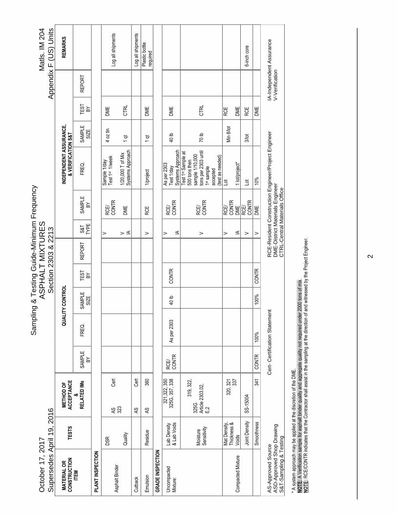
Gui
de-M
inim
um F
req
uenc
y O
ctob
er 1
7, 2
017
AS
PH
ALT
MIX
TU
RE
S
Mat
ls.
IM 2
04
Sup
erse
des
Apr
il 19
, 201
6 S
ectio
n 23
03 &
221
3 A
ppen
dix
F (
US
) U
nits
M
AT
ER
IAL
OR
C
ON
ST
RU
CT
ION
IT
EM
T
ES
TS
M
ET
HO
D O
F
AC
CE
PT
AN
CE
&
R
EL
AT
ED
IMs
Q
UA
LIT
Y C
ON
TR
OL
IND
EP
EN
DE
NT
AS
SU
RA
NC
E,
& V
ER
IFIC
AT
ION
S&
T
R
EM
AR
KS
S
AM
PLE
B
Y
FR
EQ
.
SA
MP
LE
SIZ
E
T
ES
T
BY
R
EP
OR
T
S
&T
T
YP
E
S
AM
PLE
B
Y
F
RE
Q.
S
AM
PLE
S
IZE
T
ES
T
BY
R
EP
OR
T
SO
UR
CE
INS
PE
CT
ION
Agg
rega
tes-
Coa
rse
(412
7)
A
S
209
Agg
rega
tes-
Fin
e (4
127)
AS
20
9
Hyd
rate
d Li
me
(412
7)
A
S
491.
04
Asp
halt
Bin
der
A
S
437
Em
ulsi
ons
&
Cut
back
s
AS
43
7
Rel
ease
Age
nt
A
BS
49
1.15
Rec
ycle
d A
spha
lt S
hing
les
A
S
506
PL
AN
T IN
SP
EC
TIO
N
Agg
rega
tes
(230
3)
Qua
lity
V
D
ME
1/
20,0
00 T
on
50 lb
. C
TR
L
Com
bine
d A
ggre
gate
(41
27)
Gra
datio
n
302,
336
R
CE
/ C
ON
TR
1/
lot
IM 3
01
CO
NT
R
V
IA
RC
E/
CO
NT
R
Sam
ple
1/da
y,
Tes
t 1st d
ay +
20
%
Sys
tem
s A
ppro
ach*
IM 3
01
DM
E/
RC
E
IM 2
16
IM 2
16
M
oist
ure
C
ON
TR
1
/ hal
f da
y 10
00 g
m
CO
NT
R
D
rum
Mix
Pla
nts
Onl
y
AS
-App
rove
d S
ourc
e C
ert-
Cer
tific
atio
n S
tate
men
t R
CE
-Res
iden
t C
onst
ruct
ion
Eng
inee
r/P
roje
ct E
ngin
eer
IA-I
ndep
ende
nt A
ssur
ance
A
SD
-App
rove
d S
hop
Dra
win
g
D
ME
-Dis
tric
t M
ater
ials
Eng
inee
r V
-Ver
ifica
tion
S&
T-S
ampl
ing
& T
estin
g
CT
RL-
Cen
tral
Mat
eria
ls O
ffice
AB
-App
rove
d B
rand
CO
NT
R-C
ontr
acto
r
*A p
roje
ct a
ppro
ach
may
be
appl
ied
at th
e di
scre
tion
of th
e D
ME
at t
he fr
eque
ncy
1/pr
ojec
t. N
OT
E:
RC
E/C
ON
TR
indi
cate
s th
at th
e C
ontr
acto
r sh
all a
ssis
t in
the
sam
plin
g at
the
dire
ctio
n of
and
witn
esse
d by
the
Pro
ject
Eng
inee
r.
2
Sam
plin
g &
Tes
ting
Gui
de-M
inim
um F
req
uenc
y O
ctob
er 1
7, 2
017
AS
PH
ALT
MIX
TU
RE
S
Mat
ls.
IM 2
04
Sup
erse
des
Apr
il 19
, 201
6 S
ectio
n 23
03 &
221
3 A
ppen
dix
F (
US
) U
nits
M
AT
ER
IAL
OR
C
ON
ST
RU
CT
ION
IT
EM
T
ES
TS
M
ET
HO
D O
F
AC
CE
PT
AN
CE
&
R
EL
AT
ED
IMs
Q
UA
LIT
Y C
ON
TR
OL
IND
EP
EN
DE
NT
AS
SU
RA
NC
E,
& V
ER
IFIC
AT
ION
S&
T
R
EM
AR
KS
S
AM
PLE
B
Y
F
RE
Q.
S
AM
PLE
S
IZE
T
ES
T
BY
R
EP
OR
T
S
&T
T
YP
E
S
AM
PLE
B
Y
F
RE
Q.
S
AM
PLE
S
IZE
T
ES
T
BY
R
EP
OR
T
PL
AN
T IN
SP
EC
TIO
N
Asp
halt
Bin
der
DS
R
Qua
lity
AS
C
ert
323
V
V
IA
RC
E/
CO
NT
R
DM
E
Sam
ple
1/da
y T
est 1
st 1
/wee
k 1/
20,0
00 T
of M
ix
Sys
tem
s A
ppro
ach
4 oz
tin
1 qt
DM
E
CT
RL
Lo
g al
l shi
pmen
ts
Cut
back
AS
C
ert
Lo
g al
l shi
pmen
ts
Em
ulsi
on
Res
idue
A
S
360
V
R
CE
1/
proj
ect
1 qt
D
ME
Pla
stic
bot
tle
requ
ired
GR
AD
E IN
SP
EC
TIO
N
Unc
ompa
cted
M
ixtu
re:
Lab
Den
sity
&
Lab
Voi
ds
32
1,32
2, 3
50
32
5G, 3
57, 3
38
RC
E/
CO
NT
R
As
per
2303
40
lb
CO
NT
R
V
IA
RC
E/
CO
NT
R
As
per
2303
T
est 1
/day
S
yste
ms
App
roac
h 40
lb
DM
E
M
oist
ure
Sen
sitiv
ity
319
, 322
, 32
5G
Art
icle
230
3.02
, E
,2
V
R
CE
/ C
ON
TR
Tes
t 1st S
ampl
e at
50
0 to
ns th
en
sam
ple
1/10
,000
to
ns p
er 2
303
until
1st
sam
ple
acce
pted
(t
est a
s ne
eded
)
70 lb
C
TR
L
Com
pact
ed M
ixtu
re
Mat
Den
sity
, T
hick
ness
&
Voi
ds
32
0, 3
21
33
7
V
IA
RC
E/
CO
NT
R
DM
E
Lot
1 lo
t/pro
ject
*
Min
8/lo
t
RC
E
DM
E
Join
t Den
sity
S
S-1
5004
V
RC
E/
CO
NT
R
Lot
3/lo
t R
CE
6-in
ch c
ore
S
moo
thne
ss
34
1 C
ON
TR
10
0%
100%
C
ON
TR
V
DM
E
10%
DM
E
AS
-App
rove
d S
ourc
e C
ert-
Cer
tific
atio
n S
tate
men
t R
CE
-Res
iden
t C
onst
ruct
ion
Eng
inee
r/P
roje
ct E
ngin
eer
IA-I
ndep
ende
nt A
ssur
ance
A
SD
-App
rove
d S
hop
Dra
win
g
D
ME
-Dis
tric
t M
ater
ials
Eng
inee
r V
-Ver
ifica
tion
S&
T-S
ampl
ing
& T
estin
g
CT
RL-
Cen
tral
Mat
eria
ls O
ffice
* A
sys
tem
app
roac
h m
ay b
e ap
plie
d at
the
disc
retio
n of
the
DM
E.
NO
TE
: A
Ver
ifica
tion
sam
ple
for
asph
alt b
inde
r qu
ality
and
agg
rega
te q
ualit
y no
t req
uire
d un
der
2000
tons
of m
ix.
NO
TE
: R
CE
/CO
NT
R in
dica
tes
that
the
Con
trac
tor
shal
l ass
ist i
n th
e sa
mpl
ing
at th
e di
rect
ion
of a
nd w
itnes
sed
by th
e P
roje
ct E
ngin
eer.
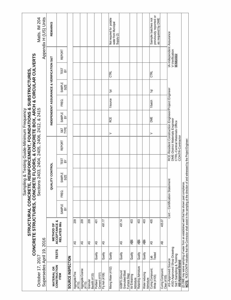
Sam
plin
g &
Tes
ting
Gui
de-M
inim
um F
req
uenc
y S
TR
UC
TU
RA
L C
ON
CR
ET
E,
RE
INF
OR
CE
ME
NT
, F
OU
ND
AT
ION
S &
SU
BS
TR
UC
TU
RE
S,
CO
NC
RE
TE
ST
RU
CT
UR
ES
, C
ON
CR
ET
E F
LO
OR
S,
& C
ON
CR
ET
E B
OX
, A
RC
H &
CIR
CU
LA
R C
UL
VE
RT
S
Oct
ober
17,
201
7 S
ectio
ns 2
403,
240
4, 2
405,
240
6, 2
412,
& 2
415
Mat
ls.
IM 2
04
Sup
erse
des
Apr
il 19
, 201
6
App
endi
x H
(U
S)
Uni
ts
MA
TE
RIA
L O
R
CO
NS
TR
UC
TIO
N
ITE
M
TE
ST
S
ME
TH
OD
OF
A
CC
EP
TA
NC
E &
R
EL
AT
ED
IMs
QU
AL
ITY
CO
NT
RO
L
IND
EP
EN
DE
NT
AS
SU
RA
NC
E &
VE
RIF
ICA
TIO
N S
&T
R
EM
AR
KS
S
AM
PLE
B
Y
FR
EQ
.
SA
MP
LE
SIZ
E
T
ES
T
BY
R
EP
OR
T
S
&T
T
YP
E
S
AM
PLE
B
Y
F
RE
Q.
S
AM
PLE
S
IZE
T
ES
T
BY
R
EP
OR
T
SO
UR
CE
INS
PE
CT
ION
Agg
rega
te-F
ine
(411
0)
A
S
209
Agg
rega
te-C
oars
e (4
115)
AS
20
9
Gra
nula
r B
ackf
ill (
4133
)
AS
20
9
Por
tland
C
emen
t (41
01)
Qua
lity
AS
40
1
Fly
Ash
(41
08)
Qua
lity
A
S
491.
17
Mix
ing
Wat
er (
4102
) Q
ualit
y
V
RC
E
1/so
urce
1p
t C
TR
L
Not
req
uire
d fo
r p
otab
le
wat
er fr
om M
unic
ipal
S
uppl
y (2
)
GG
BF
S (
Gro
und
Gra
nula
ted
Bla
st
Fur
nace
Sla
g)
Qua
lity
AS
49
1.14
Air
Ent
rain
ing
Adm
ixtu
re
Qua
lity
AB
S
403
Ret
ardi
ng A
dmix
ture
Q
ualit
y A
BS
40
3
Wat
er r
educ
ing
Adm
ixtu
re
Qua
lity
AB
S
403
Cur
ing
Com
poun
d,
Whi
te (
4105
) La
b T
este
d A
S
405
V
D
ME
1/
batc
h 1q
t C
TR
L
Sam
ple
batc
hes
not
prev
ious
ly r
epor
ted
or
as r
equi
red
by D
ME
Cur
ing
Com
poun
d,
Cle
ar (
4105
)
AB
40
5.07
AS
-App
rove
d S
ourc
e C
ert – C
ertif
icat
ion
Sta
tem
ent
RC
E-R
esid
ent
Con
stru
ctio
n E
ngin
eer/
Pro
ject
Eng
inee
r IA
-Ind
epen
dent
Ass
uran
ce
AS
D-A
ppro
ved
Sho
p D
raw
ing
DM
E-D
istr
ict
Mat
eria
ls E
ngin
eer
V-V
erifi
catio
n S
&T
-Sam
plin
g &
Tes
ting
C
TR
L-C
entr
al M
ater
ials
Offi
ce
M-M
onito
r A
B-A
ppro
ved
Bra
nd
C
ON
TR
-Con
trac
tor
(2)
DM
E m
ay w
aive
sam
plin
g of
wat
er fr
om a
n es
tabl
ishe
d w
ell t
hat h
as s
how
n pa
st c
ompl
ianc
e.
NO
TE
: R
CE
/CO
NT
R in
dica
tes
that
the
Con
trac
tor
shal
l ass
ist i
n th
e sa
mpl
ing
at th
e di
rect
ion
of a
nd w
itnes
sed
by th
e P
roje
ct E
ngin
eer.

S
ampl
ing
& T
estin
g G
uide
-Min
imum
Fre
que
ncy
ST
RU
CT
UR
AL
CO
NC
RE
TE
, R
EIN
FO
RC
EM
EN
T,
FO
UN
DA
TIO
NS
& S
UB
ST
RU
CT
UR
ES
, C
ON
CR
ET
E S
TR
UC
TU
RE
S,
CO
NC
RE
TE
FL
OO
RS
, &
CO
NC
RE
TE
BO
X,
AR
CH
& C
IRC
UL
AR
CU
LV
ER
TS
O
ctob
er 1
7, 2
017
Sec
tions
240
3, 2
404,
240
5, 2
406,
241
2, &
241
5 M
atls
. IM
204
S
uper
sede
s A
pril
19, 2
016
A
ppen
dix
H (
US
) U
nits
MA
TE
RIA
L O
R
CO
NS
TR
UC
TIO
N
ITE
M
TE
ST
S
ME
TH
OD
OF
A
CC
EP
TA
NC
E &
R
EL
AT
ED
IMs
Q
UA
LIT
Y C
ON
TR
OL
IND
EP
EN
DE
NT
AS
SU
RA
NC
E
& V
ER
IFIC
AT
ION
S&
T
R
EM
AR
KS
SA
MP
LE
BY
F
RE
Q.
S
AM
PLE
S
IZE
T
ES
T
BY
R
EP
OR
T
S
&T
T
YP
E
S
AM
PLE
B
Y
F
RE
Q.
S
AM
PLE
S
IZE
T
ES
T
BY
R
EP
OR
T
SO
UR
CE
INS
PE
CT
ION
Pre
-for
med
Joi
nt
Sea
ler
(413
6)
Lab-
Tes
ted
AB
S
436.
02
43
6.05
Rei
nfor
cing
Ste
el
Bar
s (4
151)
Q
ualit
y
AS
45
1 45
1.03
B
Ste
el P
ile (
4167
) Q
ualit
y
467
Con
cret
e P
ile (
4166
) Q
ualit
y A
S
570
Tim
ber
Pile
(41
65)
Qua
lity
C
ert
462
AS
Tim
ber
(416
2) &
Lu
mbe
r (4
163
Tre
ated
-Cer
t 46
2 A
S
Con
cret
e A
ncho
rs
Qua
lity
AB
S
453.
09
Epo
xy G
rout
Q
ualit
y A
BS
49
1.11
Con
cret
e S
eale
r Q
ualit
y A
BS
49
1.12
Sub
drai
n P
ipe
(414
3)
Qua
lity
AS
44
3, 4
48
Neo
pren
e B
earin
g P
ads
(419
5)
A
BS
49
5.03
Bro
nze
Bea
ring
Pla
tes
(419
0.03
)
AS
Cer
t
AS
-App
rove
d S
ourc
e C
ert – C
ertif
icat
ion
Sta
tem
ent
RC
E-R
esid
ent
Con
stru
ctio
n E
ngin
eer/
Pro
ject
Eng
inee
r IA
-Ind
epen
dent
Ass
uran
ce
AS
D-A
ppro
ved
Sho
p D
raw
ing
DM
E-D
istr
ict
Mat
eria
ls E
ngin
eer
V-V
erifi
catio
n S
&T
-Sam
plin
g &
Tes
ting
C
TR
L-C
entr
al M
ater
ials
Offi
ce
M-M
onito
r A
B-A
ppro
ved
Bra
nd
C
ON
TR
-Con
trac
tor
NO
TE
: R
CE
/CO
NT
R in
dica
tes
that
the
Con
trac
tor
shal
l ass
ist i
n th
e sa
mpl
ing
at th
e di
rect
ion
of a
nd w
itnes
sed
by th
e P
roje
ct E
ngin
eer.

S
ampl
ing
& T
estin
g G
uide
-Min
imum
Fre
que
ncy
ST
RU
CT
UR
AL
CO
NC
RE
TE
, R
EIN
FO
RC
EM
EN
T,
FO
UN
DA
TIO
NS
& S
UB
ST
RU
CT
UR
ES
, C
ON
CR
ET
E S
TR
UC
TU
RE
S,
CO
NC
RE
TE
FL
OO
RS
, &
CO
NC
RE
TE
BO
X,
AR
CH
& C
IRC
UL
AR
CU
LV
ER
TS
O
ctob
er 1
7, 2
017
Sec
tions
240
3, 2
404,
240
5, 2
406,
241
2, &
241
5 M
atls
. IM
204
S
uper
sede
s A
pril
19, 2
016
A
ppen
dix
H (
US
) U
nits
MA
TE
RIA
L O
R
CO
NS
TR
UC
TIO
N
ITE
M
TE
ST
S
ME
TH
OD
OF
A
CC
EP
TA
NC
E &
R
EL
AT
ED
IMs
Q
UA
LIT
Y C
ON
TR
OL
IND
EP
EN
DE
NT
AS
SU
RA
NC
E
& V
ER
IFIC
AT
ION
S&
T
R
EM
AR
KS
SA
MP
LE
BY
F
RE
Q.
S
AM
PLE
S
IZE
T
ES
T
BY
R
EP
OR
T
S
&T
T
YP
E
S
AM
PLE
B
Y
F
RE
Q.
S
AM
PLE
S
IZE
T
ES
T
BY
R
EP
OR
T
SO
UR
CE
INS
PE
CT
ION
Ste
el M
ason
ry P
late
(4
152)
AS
Cer
t
Pre
cast
Uni
ts (
2407
) Q
ualit
y A
S
570
Anc
hor
Bol
ts
(ligh
ting,
sig
ning
, ha
ndra
il, s
truc
ture
s)
(415
3)
Lab
Tes
ted
AS
D
Str
uctu
ral S
teel
(4
152)
Q
ualit
y C
ert
M
onito
r S
ampl
e A
ccor
ding
to
pla
ns o
r ot
her
inst
ruct
ions
Alu
min
um &
Ste
el
Brid
ge R
ail &
Anc
hor
Ass
embl
y
A
SD
Con
duit
(Ele
ctric
al)
(4
185.
10))
Ste
el
A
S
Con
duit
(Pla
stic
)
(418
5.10
) La
b T
este
d
V
D
ME
1/
size
4’
C
TR
L
Ben
toni
te
V
isua
l
Flo
wab
le M
orta
r La
b T
este
d
A
ppro
ved
525,
375
T
rial M
ix
T
este
d by
DM
E
Fab
ric F
orm
ed
Rev
etm
ent
A
ppro
ved
375
Tria
l Mix
Tes
ted
by D
ME
AS
-App
rove
d S
ourc
e C
ert – C
ertif
icat
ion
Sta
tem
ent
RC
E-R
esid
ent
Con
stru
ctio
n E
ngin
eer/
Pro
ject
Eng
inee
r IA
-Ind
epen
dent
Ass
uran
ce
AS
D-A
ppro
ved
Sho
p D
raw
ing
DM
E-D
istr
ict
Mat
eria
ls E
ngin
eer
V-V
erifi
catio
n S
&T
-Sam
plin
g &
Tes
ting
C
TR
L-C
entr
al M
ater
ials
Offi
ce
M-M
onito
r
C
ON
TR
-Con
trac
tor
NO
TE
: R
CE
/CO
NT
R in
dica
tes
that
the
Con
trac
tor
shal
l ass
ist i
n th
e sa
mpl
ing
at th
e di
rect
ion
of a
nd w
itnes
sed
by th
e P
roje
ct E
ngin
eer.

S
ampl
ing
& T
estin
g G
uide
-Min
imum
Fre
que
ncy
ST
RU
CT
UR
AL
CO
NC
RE
TE
, R
EIN
FO
RC
EM
EN
T,
FO
UN
DA
TIO
NS
& S
UB
ST
RU
CT
UR
ES
, C
ON
CR
ET
E S
TR
UC
TU
RE
S,
CO
NC
RE
TE
FL
OO
RS
, &
CO
NC
RE
TE
BO
X,
AR
CH
& C
IRC
UL
AR
CU
LV
ER
TS
O
ctob
er 1
7, 2
017
Sec
tions
240
3, 2
404,
240
5, 2
406,
241
2, &
241
5 M
atls
. IM
204
S
uper
sede
s A
pril
19, 2
016
A
ppen
dix
H (
US
) U
nits
MA
TE
RIA
L O
R
CO
NS
TR
UC
TIO
N
ITE
M
TE
ST
S
ME
TH
OD
OF
A
CC
EP
TA
NC
E &
R
EL
AT
ED
IMs
Q
UA
LIT
Y C
ON
TR
OL
IND
EP
EN
DE
NT
AS
SU
RA
NC
E
& V
ER
IFIC
AT
ION
S&
T
R
EM
AR
KS
SA
MP
LE
BY
F
RE
Q.
S
AM
PLE
S
IZE
T
ES
T
BY
R
EP
OR
T
S
&T
T
YP
E
S
AM
PLE
B
Y
F
RE
Q.
S
AM
PLE
S
IZE
T
ES
T
BY
R
EP
OR
T
PL
AN
T IN
SP
EC
TIO
N
Agg
rega
te-
Fin
e (4
110)
G
rada
tion
Dec
k
302,
306
336
CO
NT
R
IM 5
28
IM 3
01
CO
NT
R
8002
40
V
IA
RC
E/
CO
NT
R
Sam
ple
& T
est
1/de
ck p
our
IM 3
01
RC
E
DM
E
Pla
nt M
onito
r W
orkb
ook
See
IM 5
28
G
rada
tion
All
othe
r
CO
NT
R
IM 5
28
IM 3
01
CO
NT
R
V IA
RC
E/
CO
NT
R
1/pr
ojec
t
Sam
ple
1/w
k T
est 1
st d
ay
+20
%
IM 3
01
RC
E
DM
E
Pla
nt M
onito
r W
orkb
ook
See
IM 5
28
Sys
tem
s ap
proa
ch
appl
icab
le
M
oist
ure
30
8, 5
28
CO
NT
R
IM 5
28
IM 3
01
CO
NT
R
See
IM 5
28 if
Moi
stur
e P
robe
is u
sed
S
p. G
r.
30
7 C
ON
TR
IM
528
IM
301
C
ON
TR
Q
ualit
y A
S
209
Agg
rega
te-
Coa
rse
(411
5)
Gra
datio
n D
eck
30
2, 3
06
33
6 C
ON
TR
IM
528
IM
301
C
ON
TR
V
IA
RC
E/
CO
NT
R
Sam
ple
& T
est
1/de
ck p
our
IM 3
01
RC
E
DM
E
Pla
nt M
onito
r W
orkb
ook
See
IM 5
28
G
rada
tion
All
othe
r
CO
NT
R
IM 5
28
IM 3
01
CO
NT
R
V IA
RC
E/
CO
NT
R
1/pr
ojec
t
Sam
ple
1/w
k T
est 1
st d
ay
+20
%
IM 3
01
RC
E
DM
E
Pla
nt M
onito
r W
orkb
ook
See
IM 5
28
Sys
tem
s ap
proa
ch
appl
icab
le
M
oist
ure
30
8, 5
28
CO
NT
R
IM 5
28
2000
gm
CO
NT
R
S
p. G
r.
30
7 C
ON
TR
IM
528
20
00gm
C
ON
TR
Q
ualit
y A
S
209
V
DM
E
1/10
00 c
y 50
lb
CT
RL
(1
)
Por
tland
C
emen
t w
/c r
atio
528
C
ON
TR
1/
pour
CO
NT
R
Qua
lity
AS
C
ert
V
DM
E
1/10
00 c
y 15
lb
CT
RL
(1
)
AS
-App
rove
d S
ourc
e C
ert – C
ertif
icat
ion
Sta
tem
ent
RC
E-R
esid
ent
Con
stru
ctio
n E
ngin
eer/
Pro
ject
Eng
inee
r IA
-Ind
epen
dent
Ass
uran
ce
AS
D-A
ppro
ved
Sho
p D
raw
ing
DM
E-D
istr
ict
Mat
eria
ls E
ngin
eer
V-V
erifi
catio
n S
&T
-Sam
plin
g &
Tes
ting
C
TR
L-C
entr
al M
ater
ials
Offi
ce
M-M
onito
r
C
ON
TR
-Con
trac
tor
(1)
The
se v
erifi
catio
n sa
mpl
es fo
r co
ncre
te m
ater
ials
not
req
uire
d w
hen
mix
qua
ntity
is le
ss t
han
50 c
u. y
d.
NO
TE
: IA
may
be
acco
mpl
ishe
d by
sys
tem
app
roac
h or
on
a pe
r pr
ojec
t bas
is (
IA a
t 1 p
er 1
000
cy o
f con
cret
e) a
t the
dis
cret
ion
of t
he D
ME
acc
ordi
ng to
IM 2
07.
NO
TE
: R
CE
/CO
NT
R in
dica
tes
that
the
Con
trac
tor
shal
l ass
ist i
n th
e sa
mpl
ing
at th
e di
rect
ion
of a
nd w
itnes
sed
by th
e P
roje
ct E
ngin
eer.
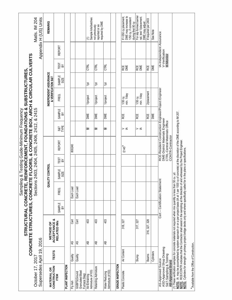
S
ampl
ing
& T
estin
g G
uide
-Min
imum
Fre
que
ncy
ST
RU
CT
UR
AL
CO
NC
RE
TE
, R
EIN
FO
RC
EM
EN
T,
FO
UN
DA
TIO
NS
& S
UB
ST
RU
CT
UR
ES
, C
ON
CR
ET
E S
TR
UC
TU
RE
S,
CO
NC
RE
TE
FL
OO
RS
, &
CO
NC
RE
TE
BO
X,
AR
CH
& C
IRC
UL
AR
CU
LV
ER
TS
O
ctob
er 1
7, 2
017
Sec
tions
240
3, 2
404,
240
5, 2
406,
241
2, &
241
5 M
atls
. IM
204
S
uper
sede
s A
pril
19, 2
016
A
ppen
dix
H (
US
) U
nits
MA
TE
RIA
L O
R
CO
NS
TR
UC
TIO
N
ITE
M
TE
ST
S
ME
TH
OD
OF
A
CC
EP
TA
NC
E &
R
EL
AT
ED
IMs
Q
UA
LIT
Y C
ON
TR
OL
IND
EP
EN
DE
NT
AS
SU
RA
NC
E
& V
ER
IFIC
AT
ION
S&
T
R
EM
AR
KS
S
AM
PLE
B
Y
F
RE
Q.
S
AM
PLE
S
IZE
T
ES
T
BY
R
EP
OR
T
S
&T
T
YP
E
S
AM
PLE
B
Y
F
RE
Q.
S
AM
PLE
S
IZE
T
ES
T
BY
R
EP
OR
T
PL
AN
T IN
SP
EC
TIO
N
Fly
Ash
Q
ualit
y A
S
Cer
t
Eac
h Lo
ad
8002
40
GG
BF
S(G
roun
d G
ranu
late
d B
last
F
urna
ce S
lag)
Qua
lity
AS
C
ert
E
ach
Load
Air-
Ent
rain
ing
Adm
ixtu
re (
4103
)
AB
40
3
M
DM
E
1/pr
ojec
t 1p
t C
TR
L
(1)
Sam
ple
lots
/bat
ches
no
t pre
viou
sly
repo
rted
or
as
requ
ired
by D
ME
Ret
ardi
ng A
dmix
ture
AB
40
3
M
DM
E
1/pr
ojec
t 1p
t C
TR
L
Wat
er R
educ
ing
Adm
ixtu
re (
4103
)
AB
40
3
M
DM
E
1/pr
ojec
t 1p
t C
TR
L
GR
AD
E IN
SP
EC
TIO
N
Pla
stic
Con
cret
e A
ir C
onte
nt
31
8, 3
27
E14
5*
V
IA
RC
E
1/30
cy,
m
in. 1
/day
RC
E
DM
E
If
>35
0 cy
pla
cem
ent,
DM
E m
ay in
crea
se to
1/
50 c
y, if
con
sist
ent
durin
g fir
st 9
0 cy
S
lum
p
317,
327
V
IA
R
CE
1/
30 c
y,
min
. 1/d
ay
R
CE
D
ME
For
slip
form
ed b
arrie
r ra
il, te
st 1
/pla
cem
ent.
DM
E m
ay a
djus
t .
B
eam
s
316,
327
, 328
RC
E
2/pl
acem
ent
R
CE
If re
quire
d pe
r 24
03
C
ylin
ders
DM
E
D
ME
See
Not
e
AS
-App
rove
d S
ourc
e C
ert – C
ertif
icat
ion
Sta
tem
ent
RC
E-R
esid
ent
Con
stru
ctio
n E
ngin
eer/
Pro
ject
Eng
inee
r IA
-Ind
epen
dent
Ass
uran
ce
AS
D-A
ppro
ved
Sho
p D
raw
ing
DM
E-D
istr
ict
Mat
eria
ls E
ngin
eer
V-V
erifi
catio
n S
&T
-Sam
plin
g &
Tes
ting
C
TR
L-C
entr
al M
ater
ials
Offi
ce
M-M
onito
r A
B-A
ppro
ved
Bra
nd
C
ON
TR
-Con
trac
tor
(1)
The
se v
erifi
catio
n sa
mpl
es fo
r co
ncre
te m
ater
ials
not
req
uire
d w
hen
mix
qua
ntity
is le
ss th
an 5
0 cu
. yd.
N
OT
E:
IA m
ay b
e ac
com
plis
hed
by s
yste
m a
ppro
ach
or o
n a
per
proj
ect b
asis
(IA
at 1
per
100
0 cy
of c
oncr
ete)
at t
he d
iscr
etio
n of
the
DM
E a
ccor
ding
to IM
207
. N
OT
E:
RC
E/C
ON
TR
indi
cate
s th
at th
e C
ontr
acto
r sh
all a
ssis
t in
the
sam
plin
g at
the
dire
ctio
n of
and
witn
esse
d by
the
Pro
ject
Eng
inee
r.
NO
TE
: C
ylin
ders
for
stre
ngth
on
prim
ary
proj
ect b
ridge
dec
ks o
nly
and
whe
re s
peci
fical
ly c
alle
d fo
r in
the
plan
s or
spe
cific
atio
ns.
*Ava
ilabl
e fr
om th
e O
ffice
of C
onst
ruct
ion.

S
ampl
ing
& T
estin
g G
uide
-Min
imum
Fre
que
ncy
ST
RU
CT
UR
AL
CO
NC
RE
TE
, R
EIN
FO
RC
EM
EN
T,
FO
UN
DA
TIO
NS
& S
UB
ST
RU
CT
UR
ES
, C
ON
CR
ET
E S
TR
UC
TU
RE
S,
CO
NC
RE
TE
FL
OO
RS
, &
CO
NC
RE
TE
BO
X,
AR
CH
& C
IRC
UL
AR
CU
LV
ER
TS
O
ctob
er 1
7, 2
017
Sec
tions
240
3, 2
404,
240
5, 2
406,
241
2, &
241
5 M
atls
. IM
204
S
uper
sede
s A
pril
19, 2
016
A
ppen
dix
H (
US
) U
nits
MA
TE
RIA
L O
R
CO
NS
TR
UC
TIO
N
ITE
M
TE
ST
S
ME
TH
OD
OF
A
CC
EP
TA
NC
E &
R
EL
AT
ED
IMs
Q
UA
LIT
Y C
ON
TR
OL
IND
EP
EN
DE
NT
AS
SU
RA
NC
E
& V
ER
IFIC
AT
ION
S&
T
R
EM
AR
KS
S
AM
PLE
B
Y
F
RE
Q.
S
AM
PLE
S
IZE
T
ES
B
Y
R
EP
OR
T
S
&T
T
YP
E
S
AM
PLE
B
Y
F
RE
Q.
S
AM
PLE
S
IZE
T
ES
T
BY
R
EP
OR
T
GR
AD
E IN
SP
EC
TIO
N
Rei
nfor
cing
Ste
el
(415
1)
Qua
lity
AS
C
ert
E
ach
Shi
pmen
t
F
ield
Boo
k V
D
ME
IM
451
6
ft C
TR
L
Rei
nfor
cing
Ste
el
Epo
xy C
oate
d (4
151)
Qua
lity
AS
C
ert
E
ach
Shi
pmen
t
F
ield
Boo
k V
D
ME
1
bar
6 ft
CT
RL
W
ill b
e ve
rific
atio
n
test
ed fo
r co
atin
g
Rei
nfor
cing
S
tain
less
Ste
el
(415
1)
Qua
lity
AS
C
ert
E
ach
Shi
pmen
t
F
ield
Boo
k V
D
ME
IM
452
6
ft C
TR
L
Ste
el P
ile (
4167
) Q
ualit
y A
S
Cer
t
Eac
h H
eat
Fie
ld B
ook
D
ME
IM
467
CT
RL
Tim
ber
Pile
(41
65)
Qua
lity
AS
46
2
Cer
t
V
DM
E
IM 4
67
C
TR
L
No
grad
e re
quire
men
t C
harg
e nu
mbe
rs o
n bu
tt en
d.
Anc
hor
Bol
ts
(ligh
ting,
sig
ning
, ha
ndra
il, s
truc
ture
s)
Lab
Tes
ted
AS
D
V
D
ME
1/
diam
eter
/ so
urce
/yea
r 1
bolt
w/n
ut &
w
ashe
r
CT
RL
S
ampl
e on
ly if
not
so
urce
insp
ecte
d
Ste
el M
ason
ry
Pla
tes
(415
2)
A
SD
C
ert
E
ach
Shi
pmen
t
F
ield
Boo
k
A
ppro
ved
by M
ater
ials
D
epar
tmen
t
Bro
nze
Bea
ring
Pla
tes
(419
0.03
) La
b T
este
d
V
D
ME
1/
proj
ect
1 on
ly
CT
RL
S
ampl
e on
ly if
not
so
urce
insp
ecte
d
Neo
pren
e B
earin
g P
ads
(419
5)
A
BS
49
5.03
Eac
h S
hipm
ent
8209
05
Alu
m. B
ridge
Rai
l &
Anc
hor
Ass
embl
y
AS
D
E
ach
Shi
pmen
t
F
ield
Boo
k
A
ppro
ved
By
Mat
eria
ls D
ept.
Dra
ins
(Std
Ste
el
Pip
e)(a
s pe
r pl
an)
Dim
ensi
ons
Gal
vani
zed
AS
D
Vis
ual
33
2
V
DM
E
1/pr
ojec
t
DM
E
AS
-App
rove
d S
ourc
e C
ert – C
ertif
icat
ion
Sta
tem
ent
RC
E-R
esid
ent
Con
stru
ctio
n E
ngin
eer/
Pro
ject
Eng
inee
r IA
-Ind
epen
dent
Ass
uran
ce
AS
D-A
ppro
ved
Sho
p D
raw
ing
DM
E-D
istr
ict
Mat
eria
ls E
ngin
eer
V-V
erifi
catio
n S
&T
-Sam
plin
g &
Tes
ting
C
TR
L-C
entr
al M
ater
ials
Offi
ce
M-M
onito
r A
B-A
ppro
ved
Bra
nd
C
ON
TR
-Con
trac
tor
NO
TE
: R
CE
/CO
NT
R in
dica
tes
that
the
Con
trac
tor
shal
l ass
ist i
n th
e sa
mpl
ing
at th
e di
rect
ion
of a
nd w
itnes
sed
by th
e P
roje
ct E
ngin
eer.

S
ampl
ing
& T
estin
g G
uide
-Min
imum
Fre
que
ncy
ST
RU
CT
UR
AL
CO
NC
RE
TE
, R
EIN
FO
RC
EM
EN
T,
FO
UN
DA
TIO
NS
& S
UB
ST
RU
CT
UR
ES
, C
ON
CR
ET
E S
TR
UC
TU
RE
S,
CO
NC
RE
TE
FL
OO
RS
, &
CO
NC
RE
TE
BO
X,
AR
CH
& C
IRC
UL
AR
CU
LV
ER
TS
O
ctob
er 1
7, 2
017
Sec
tions
240
3, 2
404,
240
5, 2
406,
241
2, &
241
5 M
atls
. IM
204
S
uper
sede
s A
pril
19, 2
016
A
ppen
dix
H (
US
) U
nits
MA
TE
RIA
L O
R
CO
NS
TR
UC
TIO
N
ITE
M
TE
ST
S
ME
TH
OD
OF
A
CC
EP
TA
NC
E &
R
EL
AT
ED
IMs
Q
UA
LIT
Y C
ON
TR
OL
IND
EP
EN
DE
NT
AS
SU
RA
NC
E
& V
ER
IFIC
AT
ION
S&
T
R
EM
AR
KS
SA
MP
LE
BY
F
RE
Q.
S
AM
PLE
S
IZE
T
ES
T
BY
R
EP
OR
T
S
&T
T
YP
E
S
AM
PLE
B
Y
F
RE
Q.
S
AM
PLE
S
IZE
T
ES
T
BY
R
EP
OR
T
GR
AD
E IN
SP
EC
TIO
N
Tim
ber
(416
2)
& L
umbe
r (4
163)
Q
ualit
y A
S
462
Tre
ated
-Cer
t
Sub
drai
n P
ipe
(414
3)
Qua
lity
AS
C
ert
443,
448
Eac
h S
hipm
ent
Flo
wab
le M
orta
r (2
506)
F
low
Tes
t
375
V
R
CE
1/
4 ho
urs
(crit
ical
) V
isua
l (n
oncr
itica
l)
R
CE
P
lant
Rep
ort
Mix
Des
ign
appr
oval
by
DM
E
Lab
mix
for
criti
cal
flow
onl
y
Gro
ut fo
r S
tone
R
evet
men
t 250
7 an
d F
abric
For
med
R
evet
men
t
Air
C
onte
nt
318
340
V
R
CE
1/
half
day
Pla
nt R
epor
t F
abric
For
med
Mix
D
esig
n ap
prov
al b
y D
ME
Flo
w T
est
375
V
R
CE
1/
half
day
F
abric
For
med
R
evet
men
t Onl
y
Com
pres
sive
S
tren
gth
315
O
nly
whe
n re
quire
d by
th
e D
ME
Ben
toni
te
Flo
w T
est
Vis
ual
375
R
CE
Har
dene
d C
oncr
ete
Sm
ooth
ness
34
1 C
ON
TR
10
0%
C
ON
TR
82
1301
V
D
ME
10
%
D
ME
AS
-App
rove
d S
ourc
e C
ert – C
ertif
icat
ion
Sta
tem
ent
RC
E-R
esid
ent
Con
stru
ctio
n E
ngin
eer/
Pro
ject
Eng
inee
r IA
-Ind
epen
dent
Ass
uran
ce
AS
D-A
ppro
ved
Sho
p D
raw
ing
DM
E-D
istr
ict
Mat
eria
ls E
ngin
eer
V-V
erifi
catio
n S
&T
-Sam
plin
g &
Tes
ting
C
TR
L-C
entr
al M
ater
ials
Offi
ce
M-M
onito
r
C
ON
TR
-Con
trac
tor
NO
TE
: R
CE
/CO
NT
R in
dica
tes
that
the
Con
trac
tor
shal
l ass
ist i
n th
e sa
mpl
ing
at th
e di
rect
ion
of a
nd w
itnes
sed
by th
e P
roje
ct E
ngin
eer.


IM
209
AG
G. P
RO
DU
CE
RS


April 18, 2017 Matls. IM 209 Supersedes April 19, 2016
1
Office of Construction & Materials
APPROVED PRODUCER PROGRAM AND CERTIFIED AGGREGATES APPROVED PRODUCER PROGRAM In order to furnish certified aggregates to projects, an aggregate producer shall be on the approved aggregate producer listing Appendix B. This will also apply to recycled product yards and/or processors. The specific requirements, including the details of the required quality control program are in Appendix A. Specification limits for aggregates being produced are found in Appendix C and the Aggregate Gradation Table in the Standard Specifications. For complete details on aggregate quality and gradation requirements, refer to the appropriate referenced specification. Non-compliance to the approved Producer Quality Control Program shall constitute grounds for the source and/or producer to be placed on conditional status by the District Materials Engineer. Continued non-compliance will be considered sufficient grounds to remove the producer from the Approved Producer List. Appendix E contains the “Notification of Violations of the Approved Producer’s Quality Control Program”. This is a written notice from the District Materials Coordinator or District Materials Engineer to a Producer identifying violation(s) of the Producer’s Quality Control Program or requirements of the Approved Producer Program. A written response is required from the Producer describing how the violation occurred, how the violation will be rectified, and what will be done so the violation will not occur or continue to occur in the future. An Aggregate Review Board will meet, as needed, for disciplinary actions and appeals involving Approved Producers. The Aggregate Review Board shall consist of: The State Construction and Materials Engineer The Chief Construction and Materials Geologist CERTIFIED AGGREGATES – SAMPLING AND TESTING The Aggregate Producer shall be responsible for source product quality control. Aggregate quality will be determined by testing samples secured by District Materials personnel. This will not relieve the producer or supplier of their responsibility for quality of the material. Producers must meet the responsibilities outlined in Guidelines for Aggregate Producer Quality Control Program, IM 209 Appendix A. Not less than 24 hours before start up, or as soon as possible for a production change, the appropriate District Materials Engineer shall be notified. The notification shall include the estimated daily production and total production, the intended use (project or warehouse stock), production ledge(s) if applicable, and responsible person(s). Failure to notify may result in additional quality sampling and testing, or rejection of the material. Aggregates to be used in highway construction projects shall be subject to sampling and testing, including Producer Quality Control (QC) sampling and testing. Sampling and testing shall be performed during production in accordance with the minimum frequencies listed in the table

April 18, 2017 Matls. IM 209 Supersedes April 19, 2016
2
below.
TABLE 1. SOURCE SAMPLING AND TESTING REQUIREMENTS
Sample Type Producer Quality Control
Testing Frequency
Iowa DOT Verification Testing
Frequency
Proportioned Aggregates
Gradation 1/1500 T(1, 4) minimum 1/18,000 T(2, 4)
Quality 1/12,000 T or 1/month,
whichever is more frequent (3)
1/12,000 T or 1/month,
whichever is less frequent (2)
Non-Proportioned Aggregates
Gradation 1/3000 T(1) minimum 1/18000 T(2)
Quality 1/12,000 T or 1/month,
whichever is more frequent (3)
1/12,000 T or 1/month,
whichever is less frequent ( 2)
Notes: 1 Additional QC testing may be required at the time material is shipped to a project, for a
stockpiled material carried over a winter season or if there is evidence of segregation, contamination, or degradation.
2 May be adjusted by the DME for source specific needs. 3 When required by the DME for sources where historic quality test results have approached or
exceeded the specification limits (IM 307, 344, and 368). 4 Variation of Fineness Modulus (FM) by more than 0.2 lower than the target fineness or more
than 0.25 greater than the target fineness modulus should be investigated.
A. Producer Quality Control Sampling & Testing Producer QC sampling and testing personnel, laboratories, and equipment shall be qualified in accordance with the Iowa DOT Technical Training & Certification Program (IM 213) and the Materials Laboratory Qualification Program (IM 208). If Producer gradation test results are used as part of an acceptance decision, they will be evaluated under the Independent Assurance Program. It is recommended that a Producer Quality Control Program include quality control testing to assist with ledge control and pit quality. Such tests may include: specific gravity (IM 307), clay lumps and friable material (IM 368), or shale in fine aggregate (IM 344). If historic data from a source indicate that quality test results approach or exceed specification limits the Engineer may require specific data be provided by the aggregate producer or supplier to the Iowa DOT (obtained by qualified persons and procedures). These data may include those tests listed above. See Table 1 for frequencies. B. Iowa DOT Verification Sampling & Testing The District Materials Office will be responsible for monitoring the Producers Quality Control Program. Verification of quality and gradation is through independent sampling and testing. Verification sampling and testing is done by Agency personnel. Agency sampling and testing personnel, laboratories, and equipment will be qualified in accordance with the Iowa DOT
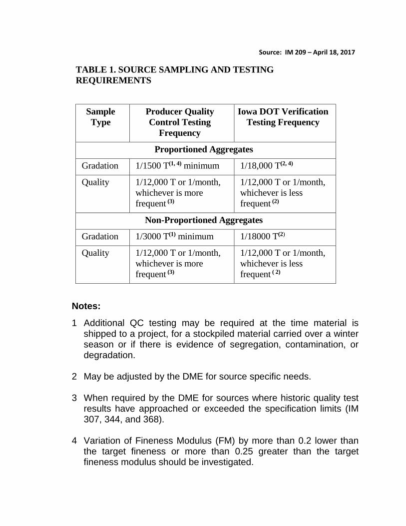
Source: IM 209 – April 18, 2017
TABLE 1. SOURCE SAMPLING AND TESTING
REQUIREMENTS
Sample
Type
Producer Quality
Control Testing
Frequency
Iowa DOT Verification
Testing Frequency
Proportioned Aggregates
Gradation 1/1500 T(1, 4) minimum 1/18,000 T(2, 4)
Quality 1/12,000 T or 1/month,
whichever is more
frequent (3)
1/12,000 T or 1/month,
whichever is less
frequent (2)
Non-Proportioned Aggregates
Gradation 1/3000 T(1) minimum 1/18000 T(2)
Quality 1/12,000 T or 1/month,
whichever is more
frequent (3)
1/12,000 T or 1/month,
whichever is less
frequent ( 2)
Notes:
1 Additional QC testing may be required at the time material is shipped to a project, for a stockpiled material carried over a winter season or if there is evidence of segregation, contamination, or degradation.
2 May be adjusted by the DME for source specific needs.
3 When required by the DME for sources where historic quality test results have approached or exceeded the specification limits (IM 307, 344, and 368).
4 Variation of Fineness Modulus (FM) by more than 0.2 lower than the target fineness or more than 0.25 greater than the target fineness modulus should be investigated.


April 18, 2017 Matls. IM 209 Supersedes April 19, 2016
3
Technical Training & Certification Program (IM 213) and the Materials Laboratory Qualification Program (IM 208). When requested by the Agency, Producer or Contractor personnel shall assist with the sampling as directed and witnessed by the certified Agency personnel. The sample location and time will be randomly selected by the Agency (except when noted elsewhere) and will only be given to the Producer immediately prior to sampling. To maintain the integrity of the sample, it will be transported by Agency personnel or secured by a tamper proof method and transported by the Producer. The Agency may spilt the verification sample and give a portion to the Producer. Verification gradation test results, when non-complying, will normally be provided to the Producer within 3 working days of sampling. At no time will the District Materials Office representative issue directions to the producer. However, the representative will have authority and responsibility to question and where necessary reject any operation, which is not in accordance with the Specifications, Special Provisions, and Instructional Memorandums. C. Validation of Non-Proportioned Aggregate Test Results The verification gradation test results will be compared to the QC test results to validate the QC results for non-proportioned aggregate. Validation is based on the verification test results being within the specification limits. When the QC test results cannot be validated, the dispute resolution process will be used. Material shall not be shipped from the stockpile until the dispute is resolved. NOTE: Verification test results may be used solely for acceptance. When verification test results are used solely for acceptance, the acceptance criteria is Article 4109. D. Dispute Resolution System Validation disputes arising between the Contracting Agency and the Producer or Contractor will be resolved in a reliable, unbiased manner usually within two weeks of notification of a dispute. If necessary, an evaluation will be performed by the Iowa DOT Central Materials Laboratory. Resolution decisions by the Iowa DOT Central Materials Laboratory will be final. Unless specified elsewhere, the District Materials Engineer will select some or all of the following steps for the dispute resolution:
1. Perform a comparison between the verification result and QC result(s) for the same time period (If the QC sample is from a split with the verification sample, also compare the previous independently taken QC result). Use the tolerances in IM 216. If the results are within the tolerance, validation is achieved.
2. Check all numbers and calculations. 3. Isolate material in dispute and begin a new stockpile. Resample stockpile material in
dispute. 4. Perform tests on split obtained by Agency personnel. 5. Review past proficiency and validation data. 6. Review sampling and testing procedures. 7. Check equipment operation, calibrations and tolerances. 8. In the event of multiple validation failures for a source, the DME may use F-test and t-
test statistical methods to compare the set of QC results with the set of verification
April 18, 2017 Matls. IM 209 Supersedes April 19, 2016
4
results. A 0.05 level of significance will be used and a set of at least 5 verification test results.
9. Involve the Central Materials Laboratory.
If the discrepancy cannot be resolved using the steps listed above then the Agency test results will be used for the acceptance decision for that lot.
E. Small Quantities
Verification sampling and testing may be waived by the DME for product quantities of less than 2000 tons. For quantities of less than 200 tons of non-critical aggregate, the DME may waive QC testing and approve the stockpile based on a visual inspection by the DME or the Engineer.
CERTIFIED AGGREGATES – DOCUMENTATION
A. Producer Test Documentation
All producer test results performed on certified aggregates, whether compliant or non-compliant, shall be reported weekly or as designated to the District Materials Engineer on Form #821278. These reports shall indicate whether the aggregate is being produced for direct project delivery, stockpiling for a specific project, or for advance warehouse stock.
Selected production limits shall be included on Form #821278.
Production limits for aggregate produced for use in HMA are generated by the contractor and supplied to the aggregate producer on Form #955.
B. Certified Aggregate Delivery Documentation
Documentation may be accomplished by numbered truck ticket, transfer list or shipment statement (such as Form #821278), or by a bill of lading (for rail or barge shipments). The certified documentation shall be furnished to project inspection personnel or receiving contractor before material is incorporated. For aggregates as bid items measured by weight (mass), the certified truck tickets shall be
numbered and include signatures or initials in accordance with Article 2001.07.
A “secure electronic signature” as defined by IM 209 Appendix G may be acceptable for certification of truck tickets in lieu of an original signature.
In the case of shipment by rail or barge, the documentation shall be sent to the project
engineer and receiving contractor or ready mix operator no later than the same day as shipment source departure. The documentation shall include the rail car or barge number(s).
Documentation not having an exact weight (mass) shall include an estimated quantity (i.e.
transfer listings or Form #821278, etc.). Non-Proportioned Aggregate Summaries
April 18, 2017 Matls. IM 209 Supersedes April 19, 2016
5
o If the Producer/Supplier QC test results are used in the acceptance decision
for non-proportioned aggregates, the Producer shall supply a signed certified summary documentation to the Project Engineer, including: the source, the type of material, the total quantity delivered, and project number.
o When Agency test results are used in the acceptance decision of for non-
proportioned aggregate, the Producer/Supplier shall supply a signed certified summary documentation to the Project Engineer and District Materials Engineer, including: the source, type of material, the total quantity delivered, and project number. The District Materials Engineer will provide test reports to the Project Engineer.
The following certification statement is required to be on the document used to certify the material being delivered (i.e. truck ticket, Form #821278, etc.): “This is to certify the material herein described meets applicable contract specifications.” NOTE: This certification statement shall be signed or initialed by an authorized representative of the aggregate supplier. To ensure proper identification of delivered aggregates, the following additional information is required on the certification document: Proportioned Aggregate When the aggregate represented is for use in HMA or PCC mixtures, the project number is preferred when practical, as in the case when shipping to a single project paving plant site, and not required when impractical, as in the case when shipping into warehouse stock at a ready mix plant or when shipping to a plant supplying material to multiple projects. PCC Aggregate: Gradation number, quantity, source name and T203 A-number, production beds (for quarried stones) and the delivery date.
HMA Aggregate: Product size, quantity, source name and T203 A-number, production beds (for quarried stones), and delivery date. Non-proportioned Aggregate Iowa DOT gradation number, project number, quantity, source name and T203 A-number and the delivery date. NOTE: Documentation for revetment stones shall include production beds. Recycled Aggregate Materials Iowa DOT gradation number, project number, quantity, source name and the delivery date. NOTE: A T203 A-number is not required for Recycled plants.
REHANDLING OF CERTIFIED AGGREGATES When certified aggregates are rehandled the District Materials Engineer shall be notified and afforded the opportunity to monitor the re-handling procedure. For the purpose of this IM, re-handling is meant to include the physical unloading and reloading of aggregate at a temporary storage site before the aggregate is delivered to its final destination.
April 18, 2017 Matls. IM 209 Supersedes April 19, 2016
6
Rehandled certified aggregates may be required to be re-tested, with or without re-weighing and recertified on a numbered shipment ticket with proper identification and certification statement. ACCEPTANCE At the Contractor’s and Producer’s own risk, aggregates may be certified for project use before quality sample test results are reported based on the following:
Complying Quality Control and Verification gradations Documentation of consistent previous compliance to specified quality requirements from
the source or ledge.
A. Proportioned Aggregate In the case of HMA or PCC proportioned aggregates, acceptance tests will be performed on verification samples obtained at the proportioning plant. Certified proportioned aggregate may be incorporated into a project on the basis of the certified truck ticket, certified bill of lading, shipment listing, certified transfer listing or Certified Gradation Test Report (Form #821278). A file of certified shipment or transfer documents for the HMA or PCC proportioned aggregate will be maintained by the contractor or ready mix operator and made available for inspection at each plant or project site during the project period. Project inspection personnel shall verify that all material incorporated in the project is properly certified and document this verification and quantity on each of the appropriate daily or periodic construction reports. No other project documentation for the incorporated aggregate is required. B. Non-Proportioned Aggregate
Acceptance of non-proportioned aggregates will be based on proper certification, visual examination by the contracting authority to ensure against obvious contamination or segregation, Producer quality control test results, and Agency verification test results. Minor quantities of non-critical aggregates may be visually inspected by the contracting authority and recorded in the project field book. Quantities less than 200 Mg (ton) are considered minor. An example of a non-critical aggregate is a non-proportioned aggregate such as granular backfill material for bridge abutments. C. Independent Assurance Program (IAP)
If Producer QC test results are used in the acceptance decision for non-proportioned aggregate, each certified technician who performs the QC sampling or testing and their test equipment will be independently checked by Iowa DOT certified technicians (IAP personnel) as per Materials IM 205 at least once per year. IAP personnel must not be involved in gradation verification testing for the aggregate source being tested.
IAP personnel will witness the Producer technician taking a random sample and splitting that sample. The splits of the sample will be tested by the Producer’s technician and by the Iowa DOT District Laboratory. District Laboratory IAP testing equipment must not be the same equipment that is used for gradation verification for that source.

April 18, 2017 Matls. IM 209Supersedes April 19, 2016
7
The results will be compared using IM 216. If acceptable correlation is not found, IAPpersonnel will contact the Producer’s technician and review the results for the following:
1. Check for recording, weighing, or calculating errors.2. Check to see that the balance is working correctly.3. Check the sieves for damage or out of tolerance openings.4. Check for overloading of sieves.5. Check for incomplete sieving.6. Resolve any problems, repeat the sampling, splitting, and observe the testing of a new
sample.
The IAP results are not to be used in the acceptance decision for the material. Any non-complying IAP results should result in a visit by the Iowa DOT inspector responsible forverification testing at that location.
This method of IAP is called a System Approach and requires the Iowa DOT to report asummary of the results annually to the FHWA. Document when the Producer’s Technician was visited, which Producer’s laboratory was used, the results, and any follow-up if required.This documentation should be retained in the event of an FHWA audit.


IM 209 C
A
GG
. QU
AL
ITY
RE
Q


A
GG
RE
GA
TE
SP
EC
IFIC
AT
ION
LIM
ITS
& S
AM
PL
ING
AN
D T
ES
TIN
G G
UID
E
Oct
ober
17,
201
7 (S
ee S
peci
ficat
ions
for
Com
plet
e D
etai
ls.)
M
atls
. IM
209
S
uper
sede
s O
ctob
er 2
1, 2
014
A
ppen
dix
C
TE
ST
LIM
ITS
S
pec
#
F &
T
A
F &
T
C
LA
A
bra
sio
n
Ab
sorp
tio
n
Ch
ert
Sh
ale
Cla
y L
um
ps
Pla
stic
In
dex
O
rgan
ic
Mat
eria
l A
l₂O
₃ L
imit
Po
re
Ind
ex
Gra
dat
ion
N
um
ber
Fin
e A
gg
reg
ate
for
PC
C
PC
C
4110
2
1
N
ote:
Max
imum
40%
bet
we
en s
ieve
s
Not
e: T
he f
inen
ess
mod
ulus
mus
t be
no lo
wer
tha
n 2.
60.
A ta
rget
fin
enes
s m
odul
us (
or b
ase
-line
) w
ill b
e es
tabl
ishe
d fo
r ea
ch s
ourc
e fo
r co
ntin
ued
appr
oval
.
N
ote:
Sh
ale
+ C
oal n
ot t
o e
xcee
d 2%
max
. P
CC
, Cla
ss L
41
11
2
1
Not
e: O
nly
from
app
rove
d P
CC
sou
rces
.
N
ote:
Ma
xim
um 4
5% b
etw
een
sie
ves
and
mus
t hav
e a
finen
ess
mod
ulus
no
low
er t
han
2.30
.
N
ote:
Sh
ale
+ C
oal n
ot t
o e
xcee
d 2%
max
. In
term
edia
te A
gg
reg
ate
for
PC
C
Cru
shed
Sto
ne a
nd P
ea
Gra
vel
4112
6
0.
5
0.5
2
N
ote:
For
Pe
a G
rave
l see
Tab
le 4
112
.03
-2 f
or m
axim
um a
llow
able
obj
ectio
nabl
e m
ater
ials
C
oar
se
Ag
gre
gat
e fo
r P
CC
C
rush
ed S
tone
41
15
-Str
uctu
ral
6
50
2 1
0.5
0.01
0.
5
3-
5 -N
onstr
uctu
ral
6
50
3 1
0.5
0.01
0.
5
3-
5
N
ote:
Se
e 41
15.0
2 f
or m
axim
um a
llow
able
obj
ectio
nab
le m
ater
ials
. G
rave
l 41
15
-Str
uctu
ral
6
35
2 1
0.5
3-
5 -N
onstr
uctu
ral
6
35
3 1
0.5
3-
5
N
ote:
Se
e 41
15.0
2 fo
r m
axim
um a
llow
able
obj
ectio
nab
le m
ater
ials
. B
ridge
Dec
k 41
15.0
5
-Surf
acin
g, R
epa
ir &
O
verlay
6
40
2.
5
0.5
0.01
0.
4
6
Not
e: U
nsou
nd C
hert
+S
hale
+C
oal+
Iro
n n
ot to
exc
eed
1%.
Not
e: U
nsou
nd C
hert
par
ticle
s ar
e de
fine
d in
411
5.02
.

A
GG
RE
GA
TE
SP
EC
IFIC
AT
ION
LIM
ITS
& S
AM
PL
ING
AN
D T
ES
TIN
G G
UID
E
Oct
ober
17,
201
7 (S
ee S
peci
ficat
ions
for
Com
plet
e D
etai
ls.)
M
atls
. IM
209
S
uper
sede
s O
ctob
er 2
1, 2
014
A
ppen
dix
C
TE
ST
LIM
ITS
S
pec
#
F &
T
A
F &
T
C
LA
A
bra
sio
n
Ab
sorp
tio
n
Ch
ert
Sh
ale
Cla
y L
um
ps
Pla
stic
In
dex
O
rgan
ic
Mat
eria
l A
l₂O
₃ L
imit
Po
re
Ind
ex
Gra
dat
ion
N
um
ber
Cla
ss V
Ag
gre
gat
e
41
17
6
40
2 (+
#16
)
7
N
ote:
Coa
rse
Agg
rega
tes
as
in 4
115
(exc
ept
abr
asio
n) a
nd F
ine
Agg
reg
ates
as
in 4
110
. C
om
bin
atio
n o
f M
ater
ials
Wit
h C
lass
V
Coa
rse
Lim
esto
ne
Li
mes
tone
Scr
eeni
ngs
N
ote:
Se
e 41
17 f
or c
emen
t req
uire
men
ts.
Not
e: A
cqu
ire li
mes
tone
fro
m s
ourc
es m
eetin
g th
e sp
eci
fied
coar
se a
ggre
gate
dur
abili
ty c
lass
for
PC
C.
Not
e: M
ust m
eet t
he r
equ
irem
ents
of
4115
an
d b
e on
ly f
rom
sou
rces
acc
epta
ble
as c
oars
e ag
greg
ate.
8
Pip
e B
edd
ing
A
ggre
gate
41
18.0
2
20
50
3
(Non
-Prim
ary
Roa
ds)
N
ote:
>7
5% C
rush
ed G
rave
l or
Cru
shed
Sto
ne.
Cru
shed
PC
C m
ay
be u
sed
if ap
pro
ved
by
the
Eng
ine
er.
Pip
e B
edd
ing
an
d B
ack
fill
A
ggre
gate
41
19.0
2
15
45
10
,11
(I
nter
stat
e an
d P
rimar
y)
N
ote:
>7
5% C
rush
ed G
rave
l or
Cru
shed
Sto
ne.
Cru
shed
PC
C m
ay
be u
sed
if ap
pro
ved
by
the
Eng
ine
er.
Gra
nu
lar
Su
rfac
ing
A
ggre
gate
for
Gra
nula
r S
houl
ders
41
20.0
2
P
er 4
120.
02
Not
e: R
equi
rem
ents
are
eq
uiva
lent
to
412
0.0
4, 4
120
.05
or 4
120
.06.
C
lass
C G
rave
l 41
20.0
3
15
10
10
N
ote:
Per
cen
t of
Cla
y Lu
mps
+ p
erce
nt p
assi
ng #
200
sie
ve n
ot t
o ex
ceed
15%
.
N
ote:
Per
cen
t of
Cla
y Lu
mps
+ p
erce
nt o
f (+
4) s
hale
+ p
erce
nt p
assi
ng
#200
not
to
exce
ed 2
0%.
Cla
ss A
Cru
shed
Sto
ne
4120
.04
15
45
4
11
Not
e: F
or s
hou
lder
s o
nly;
mat
eria
l with
Al₂O
₃ n
ot e
xcee
din
g 0.
7 or
A-f
ree
ze n
ot e
xcee
ding
10
ma
y ha
ve a
n ab
rasi
on
Sto
ne
max
imum
of
55.
Cla
ss B
Cru
shed
Sto
ne
4120
.05
20
55
4
11
Not
e: “
C”
Fre
eze +
Abra
sio
n n
ot
to e
xceed 6
5%
C
lass
D C
rush
ed S
ton
e
4120
.06
N
ote:
“C
” F
ree
ze, A
bra
sio
n,
and G
radation
to b
e s
pecifie
d b
y C
ontr
act D
ocum
ents
. P
ave
d S
hou
lder
s F
illet
s 41
20.0
7
15
45
4
11
Not
e: M
ater
ial w
ith A
l₂O
₃ n
ot e
xcee
din
g 0.
7 or
A-f
ree
ze n
ot e
xcee
din
g 1
0 m
ay
ha
ve a
n a
bras
ion
max
imum
of
55.

A
GG
RE
GA
TE
SP
EC
IFIC
AT
ION
LIM
ITS
& S
AM
PL
ING
AN
D T
ES
TIN
G G
UID
E
Oct
ober
17,
201
7 (S
ee S
peci
ficat
ions
for
Com
plet
e D
etai
ls.)
M
atls
. IM
209
S
uper
sede
s O
ctob
er 2
1, 2
014
A
ppen
dix
C
TE
ST
LIM
ITS
S
pec
#
F &
T
A
F &
T
C
LA
A
bra
sio
n
Ab
sorp
tio
n
Ch
ert
Sh
ale
Cla
y L
um
ps
Pla
stic
In
dex
O
rgan
ic
Mat
eria
l A
l₂O
₃ L
imit
Po
re
Ind
ex
Gra
dat
ion
N
um
ber
Gra
nu
lar
Su
bb
ase
41
21
25
50
1.
5
12
a(C
r. S
t.)
12b(
Gra
v.)
Not
e: C
ombi
natio
ns o
f cr
ushe
d P
CC
, sa
nd, c
rush
ed g
rave
l, or
cru
shed
sto
ne m
ay
be u
sed.
N
ote:
Sp
ecifi
catio
n lim
its a
re f
or c
rush
ed s
tone
or
crus
hed
grav
el.
Cru
shed
Sto
ne
-Bas
e
Mac
adam
Sto
ne
4122
10
50
13 (
Vis
ual)
Per
412
2.02
N
ote:
Cho
ke s
tone
se
e 4
122.
03 f
or d
eta
ils;
whe
n pr
oduc
ed f
rom
Mac
adam
has
cer
tifie
d in
spec
tion
of 1
/300
0 to
n.
Mo
dif
ied
Su
bb
ase
41
23
15
45
7
(Gra
vel)
4.7(
-#40
)
14
Not
e: M
ater
ial w
ith A
l₂O
₃ n
ot e
xcee
din
g 0.
7 (+
4) o
r A
-fre
eze
not
exc
eed
ing
10 m
ay h
ave
an a
bras
ion
max
imum
of
55.
Not
e: I
f gra
ve
l o
nly
, 7
5%
of
+3/8
” m
ust be c
rushed w
ith a
min
imum
of
one f
ractu
red f
ace.
Not
e: R
ecla
imed
pa
vem
ents
mee
ting
Mat
eria
ls IM
210
ma
y be
use
d w
ith n
o m
ore
than
50%
RA
P.
Ag
gre
gat
e fo
r S
lurr
y M
ixtu
re
41
24.0
3
10
40
5
0.01
0.
7
22
or
23
N
ote:
Fri
ctio
n T
ype
4 o
r b
ette
r, s
and
equ
iva
lent
of
not
less
than
45,
and
org
ani
c m
ater
ials
max
imum
0.0
1%.
Ag
gre
gat
e fo
r B
itu
min
ou
s S
eal
coat
4125
.03
10
40
0.
5
0.
5
1, 1
9-2
1
Not
e: F
rict
ion
Typ
e 4
or
bet
ter,
sha
le o
n sa
nd
cove
r ag
greg
ate
sha
ll no
t ex
ceed
2%
max
imum
. A
gg
reg
ate
for
Po
lym
er-M
od
ifie
d M
icro
surf
acin
g
41
26.0
3
10
40
0.5
0.5
0.01
0.
7
37
, 38
Not
e: S
and
Equ
ival
ence
of
45 M
inim
um. N
ote:
Tot
al o
f al
l com
bine
d un
sou
nd c
hert
+sh
ale
+co
al+
iron
1.0
N
ote:
For
Fric
tion
Typ
e 2
crus
hed
sto
ne r
equ
ires
Abr
asio
n lo
ss 3
0 m
ax a
nd S
and
Equ
ival
ence
of
60 M
inim
um.
Co
ars
e A
gg
reg
ate
for
HM
A
Typ
e A
41
27.0
2
10
45
6.
0
0.5
0.01
0.
7
P
er
Fo
rm 9
55
Typ
e B
Prim
ary
41
27.0
2
25
10
45
6.0
0.
01
1.5
Pe
r F
orm
95
5 N
on-P
rim
ary
41
27.0
2
45
10
45
6.0
0.
01
2.5
Pe
r F
orm
95
5
N
ote:
Org
anic
mat
eria
ls m
axim
um 0
.01%
. F
ine
Ag
gre
gat
e fo
r H
MA
4127
.03
0.
01
Pe
r F
orm
95
5
N
ote:
Nat
ura
l sa
nd s
hall
have
no
mor
e th
an 5
0% r
eta
ined
bet
wee
n tw
o co
nsec
utiv
e s
ieve
s be
low
the
#4
sie
ve.
Not
e: C
rush
ed g
rave
l or
sto
ne p
roce
ssed
fro
m c
oars
e ag
gre
gate
mee
ting
requ
ire
men
ts o
f 41
27.0
2.

A
GG
RE
GA
TE
SP
EC
IFIC
AT
ION
LIM
ITS
& S
AM
PL
ING
AN
D T
ES
TIN
G G
UID
E
Oct
ober
17,
201
7 (S
ee S
peci
ficat
ions
for
Com
plet
e D
etai
ls.)
M
atls
. IM
209
S
uper
sede
s O
ctob
er 2
1, 2
014
A
ppen
dix
C
TE
ST
LIM
ITS
S
pec
#
F &
T
A
F &
T
C
LA
A
bra
sio
n
Ab
sorp
tio
n
Ch
ert
Sh
ale
Cla
y L
um
ps
Pla
stic
In
dex
O
rgan
ic
Mat
eria
l A
l₂O
₃ L
imit
Po
re
Ind
ex
Gra
dat
ion
N
um
ber
Co
mb
inat
ion
of
Mat
eria
ls
Typ
e A
41
27.0
4
P
er
Fo
rm 9
55
Not
e: T
he f
ine
por
tion
of
com
bine
d m
ater
ials
sha
ll no
t ex
ceed
2%
sha
le r
eta
ined
on
the
#16
sie
ve.
Typ
e B
Not
e: T
he f
ine
por
tion
of
com
bine
d m
ater
ials
sha
ll no
t ex
ceed
5%
sha
le r
eta
ined
on
the
#16
sie
ve.
Sta
bili
zati
on
(F
ou
nd
atio
n)
Mat
eria
l
4128
.03
20
50
13
Rev
etm
ent
Sto
ne
Not
e: R
ocks that split
in
to la
yers
less tha
n 4
” th
ick s
hall
not
be u
se
d.
Cla
ss A
41
30.0
1
10
50
0.
7
25
Vis
ual
Cla
ss B
41
30.0
1
10
50
0.
7
25
Vis
ual
Cla
ss D
41
30.0
1
10
50
V
isua
l C
lass
E a
nd C
41
30.0
1
10
50
0.
7
25
Vis
ual
Not
e: S
ee
Spe
cific
atio
n 41
30.0
1 fo
r be
ddi
ng
pla
ne/
conc
rete
sla
b th
ickn
ess
requ
irem
ents
.
N
ote:
Se
e 41
30.0
2 fo
r gr
adat
ion
req
uire
men
ts.
Ero
sio
n a
nd
Gab
ion
Sto
ne
E
rosi
on
Sto
ne
41
30.0
5
15
50
5
V
isua
l
N
ote:
Se
e 41
30.0
4 fo
r gr
adat
ion
req
uire
men
ts.
Gab
ion
Sto
ne
41
30.0
8
10
50
0.
7
V
isua
l
N
ote:
Se
e 41
30.0
7 fo
r gr
adat
ion
req
uire
men
ts.
Po
rou
s B
ackf
ill
4131
10
50
5(+
4)
0.
7
29
N
ote:
Mat
eria
l sha
ll be
fre
e of
vis
ible
cla
y an
d o
bjec
tion
able
cla
y co
atin
g.
Sp
ecia
l Bac
kfill
41
32.0
1
30
,31
C
rush
ed S
tone
/PC
C/C
CP
/Rec
laim
ed H
MA
; M
ixtu
res
of G
rave
l, S
and
and
So
il or
Uni
form
ly b
lend
ed
com
bin
atio
ns o
f th
e ab
ove
. G
rave
l 41
32.0
3
10
31
Not
e: O
rgan
ic m
ater
ial o
f n
o m
ore
than
1%
on
frac
tion
pas
sing
the
#4
0 si
eve
. G
ran
ula
r B
ackf
ill
41
33
20
55
4
32
(se
e n
ote
2)
Not
e: “
C”
Fre
eze +
Abra
sio
n n
ot
to e
xceed 6
5%
.
N
ote:
Whe
n ba
ckfil
l is
und
er
flow
abl
e m
orta
r se
e 41
33.
04 f
or g
rada
tion
s.
Flo
od
able
Ba
ckfi
ll
41
34
Not
e: M
eet r
equi
rem
ents
for
gra
datio
ns
No.
1, 5
, or
36
.
Rec
ycle
d P
CC
N
ote:
Rec
ycle
d P
CC
and
Rec
ycle
d C
ompo
site
mus
t mee
t gra
datio
n an
d sa
mpl
ing
fre
quen
cy o
f th
e in
tend
ed
prod
uct;
and
m
eet t
he r
equ
irem
ents
of
IM 2
10.
R
ecyc
led
Co
mp
osi
te
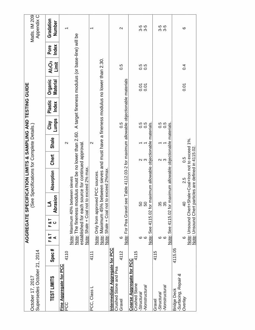
A
GG
RE
GA
TE
SP
EC
IFIC
AT
ION
LIM
ITS
& S
AM
PL
ING
AN
D T
ES
TIN
G G
UID
E
Oct
ober
17,
201
7 (S
ee S
peci
ficat
ions
for
Com
plet
e D
etai
ls.)
M
atls
. IM
209
S
uper
sede
s O
ctob
er 2
1, 2
014
A
ppen
dix
C
TE
ST
LIM
ITS
S
pec
#
F &
T
A
F &
T
C
LA
A
bra
sio
n
Ab
sorp
tio
n
Ch
ert
Sh
ale
Cla
y L
um
ps
Pla
stic
In
dex
O
rgan
ic
Mat
eria
l A
l₂O
₃ L
imit
Po
re
Ind
ex
Gra
dat
ion
N
um
ber
Fin
e A
gg
reg
ate
for
PC
C
PC
C
4110
2
1
N
ote:
Max
imum
40%
bet
we
en s
ieve
s
Not
e: T
he f
inen
ess
mod
ulus
mus
t be
no lo
wer
tha
n 2.
60.
A ta
rget
fin
enes
s m
odul
us (
or b
ase
-line
) w
ill b
e es
tabl
ishe
d fo
r ea
ch s
ourc
e fo
r co
ntin
ued
appr
oval
.
N
ote:
Sh
ale
+ C
oal n
ot t
o e
xcee
d 2%
max
. P
CC
, Cla
ss L
41
11
2
1
Not
e: O
nly
from
app
rove
d P
CC
sou
rces
.
N
ote:
Ma
xim
um 4
5% b
etw
een
sie
ves
and
mus
t hav
e a
finen
ess
mod
ulus
no
low
er t
han
2.30
.
N
ote:
Sh
ale
+ C
oal n
ot t
o e
xcee
d 2%
max
. In
term
edia
te A
gg
reg
ate
for
PC
C
Cru
shed
Sto
ne a
nd P
ea
Gra
vel
4112
6
0.
5
0.5
2
N
ote:
For
Pe
a G
rave
l see
Tab
le 4
112
.03
-2 f
or m
axim
um a
llow
able
obj
ectio
nabl
e m
ater
ials
C
oar
se
Ag
gre
gat
e fo
r P
CC
C
rush
ed S
tone
41
15
-Str
uctu
ral
6
50
2 1
0.5
0.01
0.
5
3-
5 -N
onstr
uctu
ral
6
50
3 1
0.5
0.01
0.
5
3-
5
N
ote:
Se
e 41
15.0
2 f
or m
axim
um a
llow
able
obj
ectio
nab
le m
ater
ials
. G
rave
l 41
15
-Str
uctu
ral
6
35
2 1
0.5
3-
5 -N
onstr
uctu
ral
6
35
3 1
0.5
3-
5
N
ote:
Se
e 41
15.0
2 fo
r m
axim
um a
llow
able
obj
ectio
nab
le m
ater
ials
. B
ridge
Dec
k 41
15.0
5
-Surf
acin
g, R
epa
ir &
O
verlay
6
40
2.
5
0.5
0.01
0.
4
6
Not
e: U
nsou
nd C
hert
+S
hale
+C
oal+
Iro
n n
ot to
exc
eed
1%.
Not
e: U
nsou
nd C
hert
par
ticle
s ar
e de
fine
d in
411
5.02
.

A
GG
RE
GA
TE
SP
EC
IFIC
AT
ION
LIM
ITS
& S
AM
PL
ING
AN
D T
ES
TIN
G G
UID
E
Oct
ober
17,
201
7 (S
ee S
peci
ficat
ions
for
Com
plet
e D
etai
ls.)
M
atls
. IM
209
S
uper
sede
s O
ctob
er 2
1, 2
014
A
ppen
dix
C
TE
ST
LIM
ITS
S
pec
#
F &
T
A
F &
T
C
LA
A
bra
sio
n
Ab
sorp
tio
n
Ch
ert
Sh
ale
Cla
y L
um
ps
Pla
stic
In
dex
O
rgan
ic
Mat
eria
l A
l₂O
₃ L
imit
Po
re
Ind
ex
Gra
dat
ion
N
um
ber
Cla
ss V
Ag
gre
gat
e
41
17
6
40
2 (+
#16
)
7
N
ote:
Coa
rse
Agg
rega
tes
as
in 4
115
(exc
ept
abr
asio
n) a
nd F
ine
Agg
reg
ates
as
in 4
110
. C
om
bin
atio
n o
f M
ater
ials
Wit
h C
lass
V
Coa
rse
Lim
esto
ne
Li
mes
tone
Scr
eeni
ngs
N
ote:
Se
e 41
17 f
or c
emen
t req
uire
men
ts.
Not
e: A
cqu
ire li
mes
tone
fro
m s
ourc
es m
eetin
g th
e sp
eci
fied
coar
se a
ggre
gate
dur
abili
ty c
lass
for
PC
C.
Not
e: M
ust m
eet t
he r
equ
irem
ents
of
4115
an
d b
e on
ly f
rom
sou
rces
acc
epta
ble
as c
oars
e ag
greg
ate.
8
Pip
e B
edd
ing
A
ggre
gate
41
18.0
2
20
50
3
(Non
-Prim
ary
Roa
ds)
N
ote:
>7
5% C
rush
ed G
rave
l or
Cru
shed
Sto
ne.
Cru
shed
PC
C m
ay
be u
sed
if ap
pro
ved
by
the
Eng
ine
er.
Pip
e B
edd
ing
an
d B
ack
fill
A
ggre
gate
41
19.0
2
15
45
10
,11
(I
nter
stat
e an
d P
rimar
y)
N
ote:
>7
5% C
rush
ed G
rave
l or
Cru
shed
Sto
ne.
Cru
shed
PC
C m
ay
be u
sed
if ap
pro
ved
by
the
Eng
ine
er.
Gra
nu
lar
Su
rfac
ing
A
ggre
gate
for
Gra
nula
r S
houl
ders
41
20.0
2
P
er 4
120.
02
Not
e: R
equi
rem
ents
are
eq
uiva
lent
to
412
0.0
4, 4
120
.05
or 4
120
.06.
C
lass
C G
rave
l 41
20.0
3
15
10
10
N
ote:
Per
cen
t of
Cla
y Lu
mps
+ p
erce
nt p
assi
ng #
200
sie
ve n
ot t
o ex
ceed
15%
.
N
ote:
Per
cen
t of
Cla
y Lu
mps
+ p
erce
nt o
f (+
4) s
hale
+ p
erce
nt p
assi
ng
#200
not
to
exce
ed 2
0%.
Cla
ss A
Cru
shed
Sto
ne
4120
.04
15
45
4
11
Not
e: F
or s
hou
lder
s o
nly;
mat
eria
l with
Al₂O
₃ n
ot e
xcee
din
g 0.
7 or
A-f
ree
ze n
ot e
xcee
ding
10
ma
y ha
ve a
n ab
rasi
on
Sto
ne
max
imum
of
55.
Cla
ss B
Cru
shed
Sto
ne
4120
.05
20
55
4
11
Not
e: “
C”
Fre
eze +
Abra
sio
n n
ot
to e
xceed 6
5%
C
lass
D C
rush
ed S
ton
e
4120
.06
N
ote:
“C
” F
ree
ze, A
bra
sio
n,
and G
radation
to b
e s
pecifie
d b
y C
ontr
act D
ocum
ents
. P
ave
d S
hou
lder
s F
illet
s 41
20.0
7
15
45
4
11
Not
e: M
ater
ial w
ith A
l₂O
₃ n
ot e
xcee
din
g 0.
7 or
A-f
ree
ze n
ot e
xcee
din
g 1
0 m
ay
ha
ve a
n a
bras
ion
max
imum
of
55.
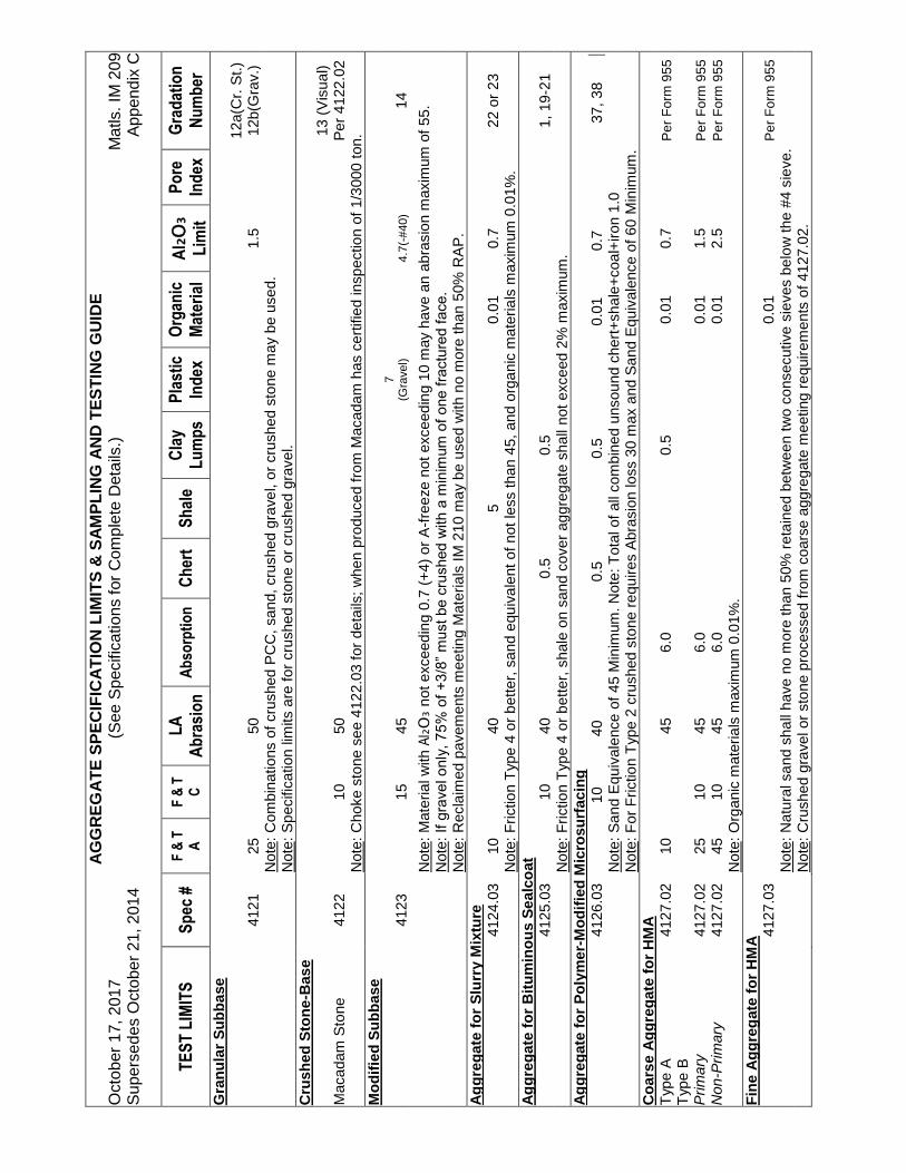
A
GG
RE
GA
TE
SP
EC
IFIC
AT
ION
LIM
ITS
& S
AM
PL
ING
AN
D T
ES
TIN
G G
UID
E
Oct
ober
17,
201
7 (S
ee S
peci
ficat
ions
for
Com
plet
e D
etai
ls.)
M
atls
. IM
209
S
uper
sede
s O
ctob
er 2
1, 2
014
A
ppen
dix
C
TE
ST
LIM
ITS
S
pec
#
F &
T
A
F &
T
C
LA
A
bra
sio
n
Ab
sorp
tio
n
Ch
ert
Sh
ale
Cla
y L
um
ps
Pla
stic
In
dex
O
rgan
ic
Mat
eria
l A
l₂O
₃ L
imit
Po
re
Ind
ex
Gra
dat
ion
N
um
ber
Gra
nu
lar
Su
bb
ase
41
21
25
50
1.
5
12
a(C
r. S
t.)
12b(
Gra
v.)
Not
e: C
ombi
natio
ns o
f cr
ushe
d P
CC
, sa
nd, c
rush
ed g
rave
l, or
cru
shed
sto
ne m
ay
be u
sed.
N
ote:
Sp
ecifi
catio
n lim
its a
re f
or c
rush
ed s
tone
or
crus
hed
grav
el.
Cru
shed
Sto
ne
-Bas
e
Mac
adam
Sto
ne
4122
10
50
13 (
Vis
ual)
Per
412
2.02
N
ote:
Cho
ke s
tone
se
e 4
122.
03 f
or d
eta
ils;
whe
n pr
oduc
ed f
rom
Mac
adam
has
cer
tifie
d in
spec
tion
of 1
/300
0 to
n.
Mo
dif
ied
Su
bb
ase
41
23
15
45
7
(Gra
vel)
4.7(
-#40
)
14
Not
e: M
ater
ial w
ith A
l₂O
₃ n
ot e
xcee
din
g 0.
7 (+
4) o
r A
-fre
eze
not
exc
eed
ing
10 m
ay h
ave
an a
bras
ion
max
imum
of
55.
Not
e: I
f gra
ve
l o
nly
, 7
5%
of
+3/8
” m
ust be c
rushed w
ith a
min
imum
of
one f
ractu
red f
ace.
Not
e: R
ecla
imed
pa
vem
ents
mee
ting
Mat
eria
ls IM
210
ma
y be
use
d w
ith n
o m
ore
than
50%
RA
P.
Ag
gre
gat
e fo
r S
lurr
y M
ixtu
re
41
24.0
3
10
40
5
0.01
0.
7
22
or
23
N
ote:
Fri
ctio
n T
ype
4 o
r b
ette
r, s
and
equ
iva
lent
of
not
less
than
45,
and
org
ani
c m
ater
ials
max
imum
0.0
1%.
Ag
gre
gat
e fo
r B
itu
min
ou
s S
eal
coat
4125
.03
10
40
0.
5
0.
5
1, 1
9-2
1
Not
e: F
rict
ion
Typ
e 4
or
bet
ter,
sha
le o
n sa
nd
cove
r ag
greg
ate
sha
ll no
t ex
ceed
2%
max
imum
. A
gg
reg
ate
for
Po
lym
er-M
od
ifie
d M
icro
surf
acin
g
41
26.0
3
10
40
0.5
0.5
0.01
0.
7
37
, 38
Not
e: S
and
Equ
ival
ence
of
45 M
inim
um. N
ote:
Tot
al o
f al
l com
bine
d un
sou
nd c
hert
+sh
ale
+co
al+
iron
1.0
N
ote:
For
Fric
tion
Typ
e 2
crus
hed
sto
ne r
equ
ires
Abr
asio
n lo
ss 3
0 m
ax a
nd S
and
Equ
ival
ence
of
60 M
inim
um.
Co
ars
e A
gg
reg
ate
for
HM
A
Typ
e A
41
27.0
2
10
45
6.
0
0.5
0.01
0.
7
P
er
Fo
rm 9
55
Typ
e B
Prim
ary
41
27.0
2
25
10
45
6.0
0.
01
1.5
Pe
r F
orm
95
5 N
on-P
rim
ary
41
27.0
2
45
10
45
6.0
0.
01
2.5
Pe
r F
orm
95
5
N
ote:
Org
anic
mat
eria
ls m
axim
um 0
.01%
. F
ine
Ag
gre
gat
e fo
r H
MA
4127
.03
0.
01
Pe
r F
orm
95
5
N
ote:
Nat
ura
l sa
nd s
hall
have
no
mor
e th
an 5
0% r
eta
ined
bet
wee
n tw
o co
nsec
utiv
e s
ieve
s be
low
the
#4
sie
ve.
Not
e: C
rush
ed g
rave
l or
sto
ne p
roce
ssed
fro
m c
oars
e ag
gre
gate
mee
ting
requ
ire
men
ts o
f 41
27.0
2.

A
GG
RE
GA
TE
SP
EC
IFIC
AT
ION
LIM
ITS
& S
AM
PL
ING
AN
D T
ES
TIN
G G
UID
E
Oct
ober
17,
201
7 (S
ee S
peci
ficat
ions
for
Com
plet
e D
etai
ls.)
M
atls
. IM
209
S
uper
sede
s O
ctob
er 2
1, 2
014
A
ppen
dix
C
TE
ST
LIM
ITS
S
pec
#
F &
T
A
F &
T
C
LA
A
bra
sio
n
Ab
sorp
tio
n
Ch
ert
Sh
ale
Cla
y L
um
ps
Pla
stic
In
dex
O
rgan
ic
Mat
eria
l A
l₂O
₃ L
imit
Po
re
Ind
ex
Gra
dat
ion
N
um
ber
Co
mb
inat
ion
of
Mat
eria
ls
Typ
e A
41
27.0
4
P
er
Fo
rm 9
55
Not
e: T
he f
ine
por
tion
of
com
bine
d m
ater
ials
sha
ll no
t ex
ceed
2%
sha
le r
eta
ined
on
the
#16
sie
ve.
Typ
e B
Not
e: T
he f
ine
por
tion
of
com
bine
d m
ater
ials
sha
ll no
t ex
ceed
5%
sha
le r
eta
ined
on
the
#16
sie
ve.
Sta
bili
zati
on
(F
ou
nd
atio
n)
Mat
eria
l
4128
.03
20
50
13
Rev
etm
ent
Sto
ne
Not
e: R
ocks that split
in
to la
yers
less tha
n 4
” th
ick s
hall
not
be u
se
d.
Cla
ss A
41
30.0
1
10
50
0.
7
25
Vis
ual
Cla
ss B
41
30.0
1
10
50
0.
7
25
Vis
ual
Cla
ss D
41
30.0
1
10
50
V
isua
l C
lass
E a
nd C
41
30.0
1
10
50
0.
7
25
Vis
ual
Not
e: S
ee
Spe
cific
atio
n 41
30.0
1 fo
r be
ddi
ng
pla
ne/
conc
rete
sla
b th
ickn
ess
requ
irem
ents
.
N
ote:
Se
e 41
30.0
2 fo
r gr
adat
ion
req
uire
men
ts.
Ero
sio
n a
nd
Gab
ion
Sto
ne
E
rosi
on
Sto
ne
41
30.0
5
15
50
5
V
isua
l
N
ote:
Se
e 41
30.0
4 fo
r gr
adat
ion
req
uire
men
ts.
Gab
ion
Sto
ne
41
30.0
8
10
50
0.
7
V
isua
l
N
ote:
Se
e 41
30.0
7 fo
r gr
adat
ion
req
uire
men
ts.
Po
rou
s B
ackf
ill
4131
10
50
5(+
4)
0.
7
29
N
ote:
Mat
eria
l sha
ll be
fre
e of
vis
ible
cla
y an
d o
bjec
tion
able
cla
y co
atin
g.
Sp
ecia
l Bac
kfill
41
32.0
1
30
,31
C
rush
ed S
tone
/PC
C/C
CP
/Rec
laim
ed H
MA
; M
ixtu
res
of G
rave
l, S
and
and
So
il or
Uni
form
ly b
lend
ed
com
bin
atio
ns o
f th
e ab
ove
. G
rave
l 41
32.0
3
10
31
Not
e: O
rgan
ic m
ater
ial o
f n
o m
ore
than
1%
on
frac
tion
pas
sing
the
#4
0 si
eve
. G
ran
ula
r B
ackf
ill
41
33
20
55
4
32
(se
e n
ote
2)
Not
e: “
C”
Fre
eze +
Abra
sio
n n
ot
to e
xceed 6
5%
.
N
ote:
Whe
n ba
ckfil
l is
und
er
flow
abl
e m
orta
r se
e 41
33.
04 f
or g
rada
tion
s.
Flo
od
able
Ba
ckfi
ll
41
34
Not
e: M
eet r
equi
rem
ents
for
gra
datio
ns
No.
1, 5
, or
36
.
Rec
ycle
d P
CC
N
ote:
Rec
ycle
d P
CC
and
Rec
ycle
d C
ompo
site
mus
t mee
t gra
datio
n an
d sa
mpl
ing
fre
quen
cy o
f th
e in
tend
ed
prod
uct;
and
m
eet t
he r
equ
irem
ents
of
IM 2
10.
R
ecyc
led
Co
mp
osi
te

IM
210
R
EC
LA
IME
D


October 17, 2017 Matls. IM 210 Supersedes October 21, 2014
1
Office of Construction & Materials
PRODUCTION OF CERTIFIED AGGREGATE FROM RECLAIMED ROADWAYS
GENERAL This IM deals with requirements for furnishing certified aggregate produced from reclaimed materials. The requirements of Office of Materials IM 209 (Certified Aggregates Approved Producer Program) also apply to the production of aggregate from reclaimed roadway materials. Processing Requirements for Aggregates Produced from Reclaimed Materials Notification to District Materials personnel of new production, as well as testing frequency, sampling, documentation, and acceptance of recycled materials, are the same as for virgin materials as outlined in IM 209. The District Materials Engineer shall be afforded the opportunity to witness the stockpiling of unprocessed recycled material. Processing of reclaimed PCC, crushed composite pavement (CCP), and salvaged HMA (RAP) shall include a means of eliminating material other than PCC, RAP, or CCP in the finished product. This may be accomplished by pre-screening or other methods acceptable to the District Materials Engineer. Stockpiles contaminated with soil or excessive recycled fines may require processing using a grizzly at the time of delivery to the recycle yard or as directed by the District Materials Engineer. Figures 1 through 6 show examples of poor (unacceptable) and clean stockpiles. Stockpiles contaminated with reinforcing steel, soil, or other material can be rejected upon visual inspection. The producer or contractor shall be informed immediately that the stockpile has been rejected. Recycled yards must have controlled access and delivered material shall be inspected prior to incorporation into unprocessed stockpiles. Moving Crusher Recycling Operations (such as a Paradigm)
If multiple crushers and screening plants are used, each plant’s production must have its own Q/C and monitor gradation testing.
Sampling and testing frequency needs to be in agreement between the Producer and DME before production.
Sampling locations must be identified using stationing, GPS, or other accurate and reliable method.
Material must be from a known aggregate source or the quality establish prior to incorporation.

October 17, 2017 Matls. IM 210 Supersedes October 21, 2014
2
Material cannot be incorporated until the material is represented by a complying gradation test result.
Modified Subbase and Granular Subbase These products require that the reclaimed material be identifiable and the following shall apply: A. For Modified Subbase: recycled crushed PCC pavement or subbase, crushed composite
pavement (CCP), and salvaged HMA (RAP) or HMA subbase can be reclaimed from an Interstate or Primary roadway pavement under the jurisdiction of the contracting authority and shall be certified based on gradation testing. If recycling subbase material, soil shall not be incorporated into the subbase. See: Modified Subbase Production, below.
B. For Granular Subbase: recycled crushed PCC pavement or subbase can be reclaimed from an Interstate or Primary roadway pavement under the jurisdiction of the contracting authority and shall be certified based on gradation testing. If recycling subbase material, soil shall not be incorporated into the subbase.
C. Recycled PCC roadway pavement or recycled composite roadway pavement obtained from secondary roads or municipal streets may be used (as described above) if the source of the aggregate is known and the PCC coarse aggregate durability is Class 2 or better and shall be certified based on gradation testing. The producer shall be responsible for documentation of the pavement source.
D. When the source or quality of the material from the secondary or municipal pavement is
unknown, the material shall be certified based on quality requirements identified in the Standard Specifications for crushed stone for the aggregate being produced and gradation requirements for the aggregate product.
1. If the concrete originated from multiple locations, the crushed material from each location
must be stockpiled in separate but homogeneous stockpiles. 2. Prior to certification and furnishing to projects, each stockpile must be readily identifiable,
and have compliant results on applicable tests on samples taken from each of these stockpiles.
E. On secondary and municipal projects, recycled material can also be reclaimed from roadway pavement under the jurisdiction of the contracting authority and shall be certified based on gradation testing.
Modified Subbase Production Some aggregate products allow the blending of RAP with virgin aggregate or crushed PCC. The virgin aggregate or crushed PCC shall meet the gradation and quality requirements of the intended product before blending with RAP. HMA shall be processed into RAP, meeting the applicable nominal maximum size for the intended product before blending with other aggregate.

October 17, 2017 Matls. IM 210 Supersedes October 21, 2014
3
The addition of unprocessed HMA shall only be allowed if it is generated from a composite pavement or consistent base layer. where the aggregate source in the PCC is Class 2 or better. This recycled composite material does not require testing. If the aggregate source in the PCC is not known, the HMA must be removed, stockpiled separately, and the recycled PCC must meet modified subbase quality specifications. If the HMA cannot be separated from the PCC, the material cannot be tested and is not allowed for use as modified subbase. Material from HMA shoulders may only be used for Special Backfill. Blending of RAP shall be accomplished by the use of belt feeders and bins equipped with adjustable gates or drive systems that can be calibrated and controlled. This is applicable to all permanent recycling operations as well as in-place recycling operations (such as the Paradigm). For Modified Subbase, the amount of recycled HMA shall not exceed 50%. RAP containing soil or other foreign material other than HMA will be considered contaminated and subject to rejection. Granular Shoulders Crushed recycled materials may total no more than 30% of the shoulder aggregate for new construction and no more than 50% of the total for existing granular shoulders. The intended proportions shall be provided to the District Materials Engineer at least 24 hours before the start of production. The District Materials Engineer shall be afforded the opportunity to witness the calibration of the blending equipment. The blending restrictions described in Modified Subbase also apply to Granular Shoulders. Recycled PCC for Class D and Class E Revetment Recycled PCC revetment must be reclaimed from Interstate or Primary roadway pavements or airport runways. To meet the nominal top size of 250 pounds for Class D and Class E revetment, recycled PCC used for revetment must be 10 inches or greater in thickness. If the Engineer or project requires using riprap containing material larger than 250 pounds, recycled PCC will not meet the dimensional requirements of Section 4130.02. Recycled PCC will not meet the dimensional requirements for Class A, B, and C revetment. Certified Aggregates Produced from Reclaimed Materials Delivery Documentation As outlined in Materials IM 209: an Iowa DOT gradation number, project number, quantity, source name and the delivery date. NOTE: A T203 A-number is not required for Recycled plants.
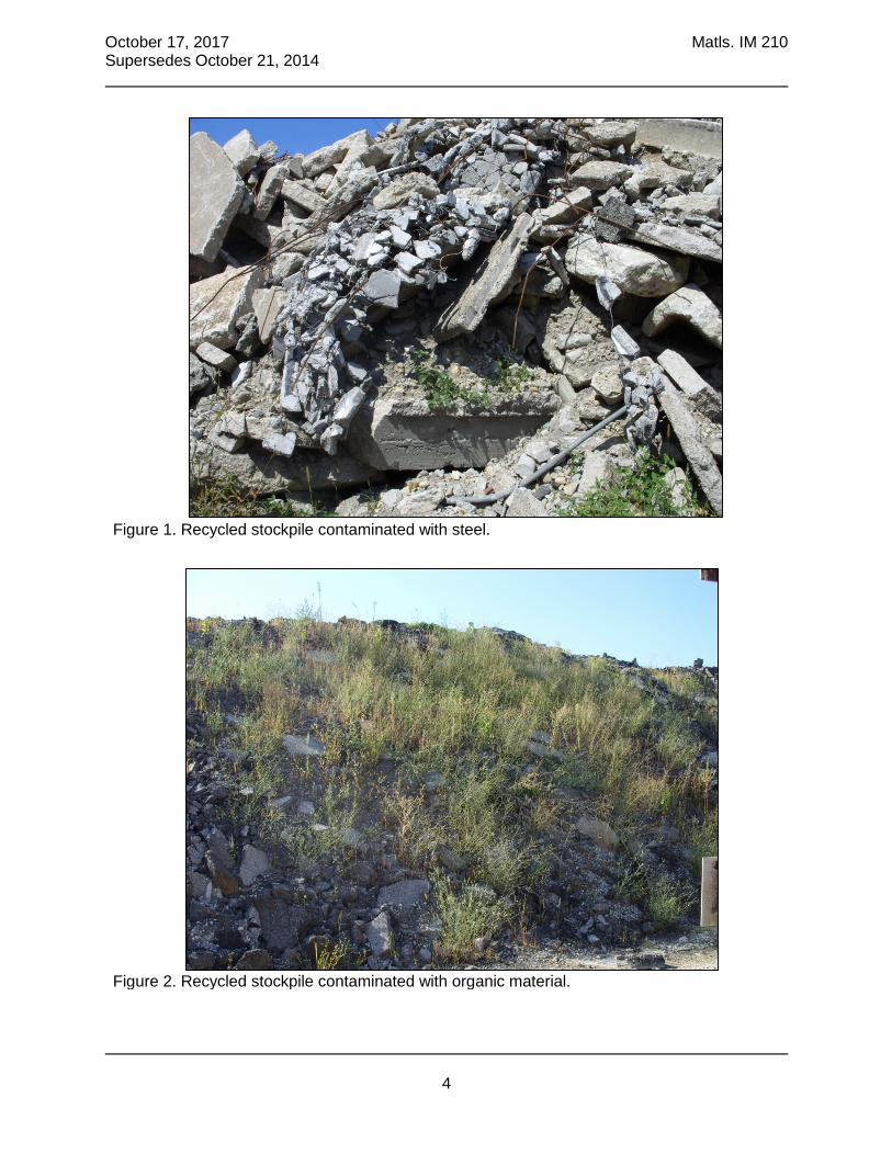
October 17, 2017 Matls. IM 210 Supersedes October 21, 2014
4
Figure 1. Recycled stockpile contaminated with steel.
Figure 2. Recycled stockpile contaminated with organic material.

October 17, 2017 Matls. IM 210 Supersedes October 21, 2014
5
Figure 3. Recycled stockpile with excessive fines.
Figure 4. Recycled stockpile contaminated with non-pavement material.
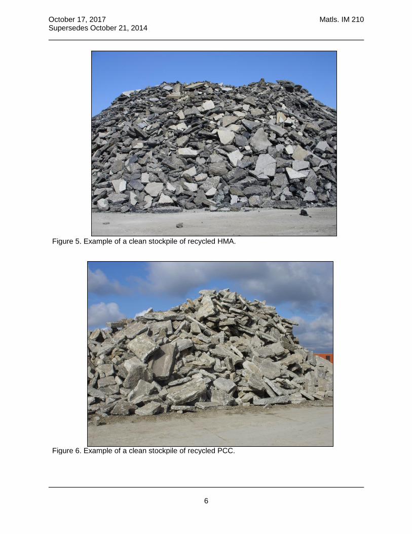
October 17, 2017 Matls. IM 210 Supersedes October 21, 2014
6
Figure 5. Example of a clean stockpile of recycled HMA.
Figure 6. Example of a clean stockpile of recycled PCC.

IM
213
TR
AIN
ING
/CE
RT
IFIC
AT
ION


April 18, 2017 Matls. IM 213 Supersedes October 18, 2016
1
Office of Construction & Materials
TECHNICAL TRAINING & CERTIFICATION PROGRAM GENERAL The purpose of the Technical Training & Certification Program is to ensure Quality Control (QC)/Quality Assurance (QA) and Acceptance of Aggregates, Hot Mix Asphalt (HMA), Portland Cement Concrete (PCC), Soils, Erosion Control, Precast and Prestressed Concrete, and Pavement Profiles and to ensure proper documentation of quality control/quality assurance and acceptance procedures and test results by industry and Contracting Authority personnel. This Instructional Memorandum (IM) explains the requirements to become certified and to remain certified to perform inspection and testing in the State of Iowa. This IM also describes the duties, responsibilities and the authority of persons assigned the position of Certified Technician in any of the above areas for construction or maintenance projects. Appendix C of this IM lists what tests and procedures the technician is qualified to perform for each level of certification they obtain. Through a cooperative program of training, study, and examination, personnel of the construction industry, State DOT, and other Contracting Authorities will be able to provide quality management and certified inspection. Quality control/quality assurance and acceptance sampling, testing and inspection will be performed by certified personnel and documented in accordance with the IMs. A technician who is qualified and holds a valid certification(s) shall perform quality control/quality assurance and acceptance at a production site, proportioning plant, or project site. Responsibilities cannot be delegated to non-certified technicians. The duties of a Certified Technician may be assigned to one or more additional Certified Technicians. The Technical Training & Certification Program will be carried out in accordance with general policy guidelines established or approved by the Highway Division Director. A Board of Certification composed of the following members will advise the Director: Director – Office of Construction and Materials Representative of District Materials Engineers** Representative of District Construction Engineers** Representative of Associated General Contractors (AGC of Iowa) Representative of Iowa Concrete Paving Association (ICPA) Representative of Asphalt Paving Association of Iowa (APAI) Representative of Iowa Ready Mixed Concrete Association (IRMCA) Representative of Iowa Limestone Producers Association (ILPA) Representative of County Engineers Representative of American Council of Engineering Companies (ACEC-Iowa) Coordinator of Technical Training & Certification Program** ** Appointed by Program Director The Director of the Office of Construction and Materials will be the Program Director. Coordinators will be appointed by the Program Director to assist in administration of the program and to handle such planning, administration, and coordinating functions as may be needed.

April 18, 2017 Matls. IM 213 Supersedes October 18, 2016
2
TRAINING The Iowa DOT or an agency approved by the Program Director will provide the training necessary to become certified. Producers/Contractors are encouraged to conduct their own pretraining program. A complete listing of training opportunities is available at the Technical Training & Certification Program website, www.iowadot.gov/training/ttcp.html https://iowadot.gov/training/technical-training-and-certification-program. CERTIFICATION REQUIREMENTS 1. A candidate must attend Iowa DOT course instruction and pass the examination(s) for all
levels of certification prepared and presented by the Program Director or someone designated by the Program Director. If the new candidate fails the examination, they will have one opportunity to retake the examination. The retake must be completed within six months of the original exam. If they fail the retake of the examination, they will need to attend the training again before taking the examination the third time. If an individual is recertifying they will have only one opportunity to take the examination. If they fail the examination they must take the applicable training before retaking the examination.
2. All prerequisites shall be met before the applicant may attend the next level of training for the
certification desired. A listing of certification levels and prerequisites is located in Appendix A. 3. Once the candidate has met all the criteria and has received certification, it is recommended
the Certified Technician work under the supervision of an experienced technician until they become efficient in the inspection and testing methods they will be performing.
An individual requesting to become certified as a Precast/Prestress Concrete Technician is required to obtain forty hours of experience assisting in quality control inspection at an approved plant before certification will be issued. The experience must be documented and shall be approved by the District Materials Engineer. This experience must be completed within two years from the date the individual attended the training.
4. Registered Professional Engineers, engineering graduates, and geology graduates from
accredited institutions will be exempt from the training requirement in the areas they have had instruction. It is, however, strongly recommended that they attend the certification classes. In order to obtain certification for any technical level, these persons must pass all applicable tests written examinations for the level of certification they wish to obtain. If the written examination attempt does not meet the required score, the candidate must take the certification class before another attempt can be made. All certificates issued in accordance with these requirements will be subject to the same regulations concerning expiration, recertification, etc., as applies to certificates obtained via training and examinations.
5. Technicians will be issued certifications by reciprocity when the following criteria are met:
a. The applicant must be certified in another state or certification program determined equivalent by the Program Director or someone designated by the Program Director, in each level of certification they are requesting.
b. The applicant must pass an examination for each level of certification desired, which will
be administered by the Iowa Department of Transportation. Failure of the examination shall require the applicant to take the applicable schooling before they can retake the exam.

April 18, 2017 Matls. IM 213 Supersedes October 18, 2016
3
c. The applicant must follow the prerequisite requirements of the Technical Training &
Certification Program. Reciprocity requests should be made through the Technical Training and Certification office in Ames. Copies of all the applicant’s certifications will be required. CERTIFICATION Upon successfully completing the requirements for certification, the Program Director will issue a pocket certification card. The certification is not transferable. A certification shall be valid for five years. CERTIFICATION IDENTIFICATION The certification card will identify the certificate holder, their certification number, the level(s) of certification, and the expiration date of each level. RENEWAL OF CERTIFICATION A certification shall be valid through December 31st of the fifth year. A 90-day grace period will be allowed. If the individual has not renewed their certification within the 90-day grace period, they are automatically decertified. The individual may obtain certification by taking the examination for the level of certification they are requesting. If the individual does not take the examination within one year after their certification(s) expire, i.e., 12/31/expiration year, they must retake all applicable schooling and pass the examinations. If an applicant becomes decertified in any level of certification and that certification is a prerequisite for other levels of certification the applicant will also be decertified in those related levels of certification. All certified technicians will be required to pass an examination in each level of certification they hold before recertification will be issued. Failure of any level shall require the applicant to retake the applicable schooling and pass the test. The certificate holder shall be responsible for applying for certification renewal and for maintaining a current address on file. Technicians certified as Level I HMA and/or Level II PCC shall attend a minimum of two update classes each in the five-year period between certification and each recertification. Technicians certified in Erosion Control must take one update class in the five-year period between certification and each recertification. The Iowa DOT or an agency or organization approved by the TTCP will hold these classes. These update classes will be listed on the TTCP website, or the certified technician may contact the Iowa DOT for information. The updates are also available as web based courses. If an individual does not attend the update class required before their certification expires, they must take the entire schooling and pass the examination for the certification required. The certified technician will not receive credit for the following: 1. More than one update per training season in each level of certification. 2. An update taken during the same training season in which the individual certifies or recertifies. PROVISIONAL CERTIFICATION Provision certification will be allowed through a special request to the TTCP Director. The request can be mailed or emailed to the TTCP Director and must include the need for a provisional

April 18, 2017 Matls. IM 213 Supersedes October 18, 2016
4
certification, such as, company technician quit and they need to replace, an unforeseen workload, etc. Provisional certifications will only be granted to contractors. If the request is granted the following requirements will apply.
1. The provisional certification applicant must work under the direct supervision of a certified technician until such time that the certified technician applicant is competent in the required skills of the certification and has taken the written exam. The applicant must also take the web based review offered by the TTCP in the area they are seeking provisional certification.
2. The applicant must take and pass the written exam for the provisional certification they are requesting. There will be a testing fee in the amount of the TTCP recertification fee due at the time of the exam. CIT funds may not be used for provisional certification testing. The exams will be offered at the District Materials offices or the TTCP office in Ames.
3. The technician must demonstrate proficiency to an Iowa DOT certified technician at the first available opportunity.
4. After the provisional certification applicant has successfully completed the steps in 1 and 2, they will become provisionally certified until the end of the calendar year in which they obtained certification.
5. If the provisional certified technician wishes to keep their certification they must attend the full class at the full class cost for the certification during the training season immediately following their provisional certification.
6. A provisional certified is not intended to be an annual request. The provisional certification will only be allowed for one construction season. Repeated requests for provisional certifications for the technician will be denied.
7. Any prerequisites for the certification must be met prior to number 2 above. 8. Basic HMA Basic Tester Testing is a new certification that may only be used as a
provisional certification. This certification follows all the requirements previously listed and the technician will be required to take Level I HMA at the first available opportunity after the provisional expires.
9. Provisional Certification will be offered for: a. Level I Aggregate Aggregate Sampler b. Level II Aggregate Aggregate Technician c. Level I PCC d. PCC Basic Tester Concrete Testing e. HMA Sampler f. HMA Basic Tester HMA Testing
UNSATISFACTORY PERFORMANCE NOTICE A certified technician failing to perform the required specified duties or inadequately performing these duties, will receive an Unsatisfactory Notice (Office of Materials IM 213, Appendix B). The notice will be from the District Materials Engineer in the District where the failure occurred. This notice and all supporting documentation will be placed in the technician’s permanent file with the District Materials Office in which the technician resides. The notice will also be placed on the statewide computer file. The notice will remain in their file for five years. The notice may be removed prior to the five years upon the recommendation of the District Materials Engineer.

April 18, 2017 Matls. IM 213 Supersedes October 18, 2016
5
SUSPENSION A technician receiving two Unsatisfactory Work Performance Notices for work performed under a specific certification will be given a three-month suspension of the applicable certification. Suspended technicians shall not perform any duties governed by the suspended certification, including any duties which require the suspended certification as a prerequisite. Technicians are eligible to be reinstated after the three-month suspension and successful completion of the applicable recertification test(s).
Technicians are subject to decertification when they receive a third Unsatisfactory Performance Notice. The suspension will be effective on the date the Program Director issues the suspension.
DECERTIFICATION
Certified Technicians will be decertified for any of the following reasons: Certifications will be revoked for the following reasons: 1. Failure of the certificate holder to renew the certificate prior to regular expiration as described
above.
2. Use of false or fraudulent information to secure or renew a certificate.
3. Use of false or fraudulent documentation by the certificate holder.
4. Use of misleading, deceptive, untrue or fraudulent representations by the certificate holder.
5. Not performing tests and technician duties properly and in accordance to specifications.
6. Cheating on certification exams or performance evaluations. This includes removing or attempts to remove exam questions, answers, or other exam materials from the testing location.
7. Receipt of 3 Unsatisfactory Performance notifications, as stated above under suspension. The Program Director, or designee, will notify an individual in writing of the intent to suspend or revoke the individual’s certification(s). Notice will also be sent to the technician’s last known employer. For DOT employees, notice will also be sent to their immediate supervisor. An individual’s certifications will be suspended during the appeal process and the individual can’t perform any duties governed by the certification during this time until the first day following the end of the appeal process, described below. Technicians that are decertified shall not perform any duties requiring certification. APPEALS & REINSTATEMENT REQUESTS An individual has 10 business days to respond to the revocation notice. If the individual fails to respond with an appeal within 10 days of receipt of the original revocation notice, the suspension or revocation becomes effective on the 10th day. Appeal step 1: First step appeals will be heard by the program director and a representative panel. The individual will have an opportunity to present information to support their continued

April 18, 2017 Matls. IM 213 Supersedes October 18, 2016
6
certification to the panel. The Program Director and representative panel will then render a written decision, taking into account the technician’s actions or omissions, the existence of past infractions, and any mitigating factors. This step 1 appeal will become final if further action is not taken as described in appeal step 2 and the suspension or revocation will become effective on the day the decision is issued by the panel. Appeal step 2: If the individual is not satisfied with the decision of the Program Director and representative panel, the individual shall, within 10 days of receipt of the written decision, submit a request for further review to the Program Director. This appeals request will be considered by the entire Certification Board. The decision of the Certification Board will be the final decision on behalf of Technical Training & Certification Program. Any violation will remain on the violator’s record for five years, at which time the violation will be removed from their record. A technician may request reinstatement after one year of being decertified unless the Program Director authorized a shorter period of time, which shall not be less than three months. If a reinstatement is authorized, the individual must attend and successfully complete the applicable certification courses. FUNCTIONS & RESPONSIBILITES A certificate holder at each production site, project site, proportioning plant, or laboratory will perform duties. The certified technician shall perform quality control testing in accordance with specified frequencies and submit designated reports and records. The specification requirement for materials testing by a certified technician does not change the supplier’s responsibilities to furnish materials compliant with the specification requirements. The District Materials Engineer and/or Project Engineer will be responsible for monitoring the sampling, testing, production inspection activities and quality control performed by the contractor. A monitor shall have satisfactorily completed the training and be certified for the level of technician they are monitoring. The District Materials Engineer and/or Project Engineer will have authority and responsibility to question and where necessary, require changes in operations and quality control to ensure specification requirements are met. QUALITY CONTROL, TESTING, & DOCUMENTATION The QC Technician shall be present whenever construction work related to production activity, such as stockpiling or other preparatory work, requires record development and/or documentation is in progress. The QC Technician’s presence is normally required on a continuing basis beginning one or more days before plant operation begins and ending after plant shut down at the completion of the project. The work shall be performed in a timely manner and at the established frequencies.
The QC Technician’s presence is not normally required during temporary plant shut downs caused by conditions, such as material shortages, equipment failures, or inclement weather.
All quality control activities and records shall be available and open for observation and review by representatives of the contracting authority.

April 18, 2017 Matls. IM 213 Supersedes October 18, 2016
7
Reports, records, and diaries developed during progress of construction activities will be filed as directed by the Contracting Authority and will become the property of the Contracting Authority. Quality control activities, testing, and records will be monitored regularly by Contracting Authority representatives. The Project Engineer or District Materials Engineer will assign personnel for this function. Monitor activities will be reported and filed at prescribed intervals with the Project Engineer, District Materials Engineer, producer, contractor, and the contractor’s designated producer. At no time will the monitor inspector issue directions to the contractor, or to the QC Technician. However, the monitor inspector will have the authority and responsibility to question, and where necessary, reject any operation or completed product, which is not in compliance with contract requirements. ACCEPTANCE Completed work will be accepted on the basis of specification compliance documented by acceptance test records, and monitor inspection records. Specification noncompliance will require corrective action by the producer, contractor, or by the contractor’s designated producer, and review of events and results associated with noncompliance by the Project Engineer.

October 17, 2017 Matls. IM 213 Supersedes April 18, 2017 Appendix A
CERTIFICATION LEVELS
CERTIFICATION LEVEL TITLE PRE-REQUISITES
AGGREGATE Aggregate Sampler Certified Sampling Technician None Aggregate Technician Certified Aggregate Technician Level I Aggregate None
PORTLAND CEMENT CONCRETE PCC Basic Concrete Tester** PCC Basic Concrete Tester None Level I PCC** PCC Testing Technician None Level II PCC PCC Plant Technician Agg. Technician & Level I PCC Level III PCC PCC Mix Design Technician Level II PCC **American Concrete Institute (ACI) Grade I certification will be acceptable as a portion of the Level I PCC and PCC Basic Concrete Tester training.
HOT MIX ASPHALT HMA Sampler HMA Sampler None Level I HMA HMA Technician Aggregate Technician Level II HMA HMA Mix Design Technician Level I HMA
PROFILOGRAPH Profilograph Profilograph Technician None
PRESTRESS Prestress Prestress Technician Level I PCC or ACI Grade I
If the technician will be performing gradations, they will need to be Aggregate Level II- certified.
SOILS Soils Soils Technician None
EROSION CONTROL Erosion Control Erosion Control Technician None

October 15, 2013 Matls. IM 213 Supersedes October 18, 2005 Appendix B
1
UNSATISFACTORY PERFORMANCE NOTICE
Issued To: Date:
This notice is to inform you that your performance as a Certified Inspector/Technician was unsatisfactory for the reason(s) listed below. This notice will be placed in your permanent file with the District Materials Office in which you reside. It will also be placed on the statewide computer file. The goal of the Technical Training and Certification Program (TTCP) is to work with contractors, producers, cities, and counties to continually improve the quality of Iowa’s construction projects. We hope you will work with us to achieve this goal. Unsatisfactory Performance: District Materials Engineer cc: Program Director –Construction and Materials Engineer, Ames TTCP Coordinator Resident Construction Engineer
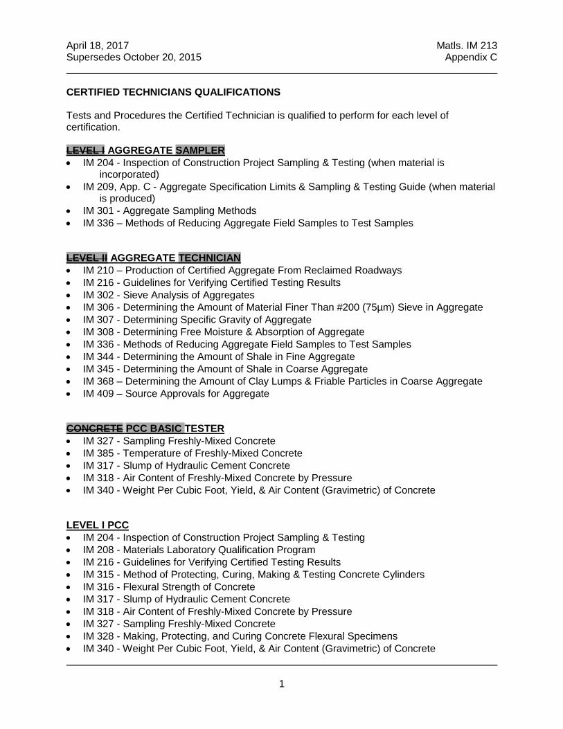
April 18, 2017 Matls. IM 213 Supersedes October 20, 2015 Appendix C
1
CERTIFIED TECHNICIANS QUALIFICATIONS Tests and Procedures the Certified Technician is qualified to perform for each level of certification. LEVEL I AGGREGATE SAMPLER IM 204 - Inspection of Construction Project Sampling & Testing (when material is
incorporated) IM 209, App. C - Aggregate Specification Limits & Sampling & Testing Guide (when material
is produced) IM 301 - Aggregate Sampling Methods IM 336 – Methods of Reducing Aggregate Field Samples to Test Samples LEVEL II AGGREGATE TECHNICIAN IM 210 – Production of Certified Aggregate From Reclaimed Roadways IM 216 - Guidelines for Verifying Certified Testing Results IM 302 - Sieve Analysis of Aggregates IM 306 - Determining the Amount of Material Finer Than #200 (75µm) Sieve in Aggregate IM 307 - Determining Specific Gravity of Aggregate IM 308 - Determining Free Moisture & Absorption of Aggregate IM 336 - Methods of Reducing Aggregate Field Samples to Test Samples IM 344 - Determining the Amount of Shale in Fine Aggregate IM 345 - Determining the Amount of Shale in Coarse Aggregate IM 368 – Determining the Amount of Clay Lumps & Friable Particles in Coarse Aggregate IM 409 – Source Approvals for Aggregate CONCRETE PCC BASIC TESTER IM 327 - Sampling Freshly-Mixed Concrete IM 385 - Temperature of Freshly-Mixed Concrete IM 317 - Slump of Hydraulic Cement Concrete IM 318 - Air Content of Freshly-Mixed Concrete by Pressure IM 340 - Weight Per Cubic Foot, Yield, & Air Content (Gravimetric) of Concrete LEVEL I PCC IM 204 - Inspection of Construction Project Sampling & Testing IM 208 - Materials Laboratory Qualification Program IM 216 - Guidelines for Verifying Certified Testing Results IM 315 - Method of Protecting, Curing, Making & Testing Concrete Cylinders IM 316 - Flexural Strength of Concrete IM 317 - Slump of Hydraulic Cement Concrete IM 318 - Air Content of Freshly-Mixed Concrete by Pressure IM 327 - Sampling Freshly-Mixed Concrete IM 328 - Making, Protecting, and Curing Concrete Flexural Specimens IM 340 - Weight Per Cubic Foot, Yield, & Air Content (Gravimetric) of Concrete
April 18, 2017 Matls. IM 213 Supersedes October 20, 2015 Appendix C
2
IM 347 – Measuring Length of Drilled Concrete Cores IM 383 - Testing the Strength of PCC Using the Maturity Method IM 385 - Temperature of Freshly-Mixed Concrete IM 525 - Designing Flowable Mortar Iowa 410-B - Method of Test for Flow of Grout Mixtures AASHTO T97 - Third Point Loading LEVEL II PCC IM 527 - Paving Plant Inspection IM 528 - Structural Concrete Plant Inspection IM 529 - PC Concrete Proportions LEVEL III PCC IM 530 - Quality Management & Acceptance of PC Concrete Pavement IM 531 - Test Method for Combining Aggregate Gradations IM 532 - Aggregate Proportioning Guide for Portland Cement Concrete Pavement BASIC HMA BASIC TESTER TESTING (This is for Provisional Certification Only) IM 321 - Method of Test for Compacted Density of Hot Mix Asphalt (HMA) (Displacement IM 322 - Method of Sampling Uncompacted Hot Mix Asphalt IM 323 - Method of Sampling Asphaltic Materials IM 325G - Method of Test for Determining the Density of Hot Mix Asphalt (HMA) Using the
Superpave Gyratory Compactor (SGC) IM 350 - Maximum Specific Gravity of Hot Mix Asphalt (HMA) Mixtures IM 357 - Preparation of Hot Mix Asphalt (HMA) Mix Samples for Test Specimens All forms must be signed by an HMA I or HMA II certified technician HMA SAMPLER IM 320 – Method of Sampling Compacted Asphalt Mixtures IM 321 – Method of Test for Compacted Density of Hot Mix Asphalt (HMA) (Displacement
Method) IM 322 - Method of Sampling Uncompacted Hot Mix Asphalt IM 323 - Method of Sampling Asphaltic Materials LEVEL I HMA IM 204 - Inspection of Construction Project Sampling & Testing IM 208 - Materials Laboratory Qualification Program IM 216 - Guidelines for Verifying Certified Testing Results IM 320 - Method of Sampling Compacted Asphalt Mixtures IM 321 - Method of Test for Compacted Density of Hot Mix Asphalt (HMA) (Displacement) IM 322 - Method of Sampling Uncompacted Hot Mix Asphalt IM 323 - Method of Sampling Asphaltic Materials

April 18, 2017 Matls. IM 213 Supersedes October 20, 2015 Appendix C
3
IM 325G - Method of Test for Determining the Density of Hot Mix Asphalt (HMA) Using the Superpave Gyratory Compactor (SGC)
IM 337 - Determining Thickness of Completed Courses of Base, Subbase, & Hot Mix Asphalt IM 350 - Maximum Specific Gravity of Hot Mix Asphalt (HMA) Mixtures IM 357 - Preparation of Hot Mix Asphalt (HMA) Mix Samples for Test Specimens IM 501 - Asphaltic Terminology, Equations & Example Calculations IM 508 - Hot Mix Asphalt (HMA) Plant Inspection IM 509 - Tank Measurement & Asphalt Cement Content Determination IM 511 - Control of Hot Mix Asphalt (HMA) Mixtures LEVEL II HMA IM 380 - Vacuum-Saturated Specific Gravity & Absorption of Combined or Individual
Aggregate Sources IM 510 - Method of Design of Hot Mix Asphalt (HMA) Mixes AASHTO T176 - Plastic Fines in Graded Aggregate & Soils by use of Sand Equivalent Test AASHTO T304 - Uncompacted Void Content of Fine Aggregate ASTM D 4791 - Flat Particles, Elongated Particles, or Flat & Elongated Particles in Coarse
Aggregate AASHTO T283 Resistance of Compacted Hot Mix Asphalt (HMA) to Moisture-Induced
Damage PROFILOGRAPH IM 341 - Determining Pavement & Bridge Ride Quality PRESTRESS IM 570 - Precast & Prestressed Concrete Bridge Units SOILS IM 309 – Determining Standard Proctor Moisture Density Relationship of Soils IM 312 – Sampling of Soils for Construction Project IM 335 – Determining Moisture Content of Soils ASTM D-2937 – Field density by drive-cylinder method
April 19, 2016 Matls. IM 213 Supersedes April 21, 2015 Appendix D
1
AGGREGATE TECHNICIAN DUTIES Duties of the Aggregate Technician are detailed in IM 209 and the IM 300 Series and consist of, but are not limited to the following: A. Sampling
1. Obtain representative samples by approved method(s). 2. Sample at required frequencies. 3. Identify samples with pertinent information such as:
a. Type of material b. Intended use c. Production beds working depth d. Sampling method
4. Reduce samples by approved method(s).
B. Gradation Testing
1. Follow appropriate testing methods. 2. Maintain current applicable specifications. 3. Post test results within 24 hours of sampling.
C. Other Testing as required (specific gravity, moisture, deleterious material, etc.) 1. Follow appropriate testing methods. 2. Maintain current applicable specifications. 3. Complete required reports.
D. Sampling & Testing Equipment 1. Clean and check testing sieves for defects. 2. Assure scale accuracy. 3. Maintain sampling and testing equipment.
E. Communication
April 19, 2016 Matls. IM 213 Supersedes April 21, 2015 Appendix D
2
1. Notify the District Materials office for production start-up or changes. 2. Relay test results to appropriate production or supervisory personnel. 3. Report failing test results immediately to appropriate personnel (including District
Materials office) and assure remedial actions are taken.
F. General 1. Monitor stockpiling procedures to avoid contamination and excess segregation. 2. Assure proper identification of stockpiles. 3. Assure specification requirements for intended use are met before shipment. 4. Assure sampling locations are safe. 5. Assure proper bedding planes or production depths are maintained.
G. Documentation
1. Report all production test results of certified aggregates on Form #821278 and distribute as required.
2. Assure “plant production log” is maintained.

April 19, 2016 Matls. IM 213 Supersedes April 21, 2015 Appendix D
3
PORTLAND CEMENT CONCRETE (PCC) TECHNICIAN DUTIES PAVING & STRUCTURAL CONCRETE
The Quality Control Technician shall have no other duties while performing certified inspection duties. Refer to IM 528 for exceptions. The District Materials Engineer may approve all quality control activities be performed by a single certified technician for low production situations. Many of the duties of the PCC Level II Technician are detailed in IM 527 (Paving) and IM 528 (Structural) and consist of, but are not limited to the following: A. Stockpiles
1. Assure proper stockpiling procedures. 2. Prevent intermingling of aggregates. 3. Prevent contamination. 4. Prevent segregation.
B. Plant Facilities 1. Assure safe sampling locations. 2. Check for equipment compliance. 3. Assure proper laboratory location and facilities.
C. Calibration 1. Be present during calibration (paving). 2. Check plant calibration (structural). 3. Assure proper batch weights.
D. Cement (Fly Ash) & Aggregate Delivery 1. Check for proper sources and certification. 2. Document quantities delivered. 3. Monitor condition of shipments.
E. Plant Sampling 1. Check aggregate gradations by obtaining, splitting, and testing samples.

April 19, 2016 Matls. IM 213 Supersedes April 21, 2015 Appendix D
4
2. Check aggregate moistures and specific gravity.
F. Proportion Control 1. Check scale weights and operation. 2. Check admixture dispensers. 3. Check mixing time and revolutions. 4. Check cement yield. (Paving plant only, unless over 10,000 cu. yds.)
G. Concrete Tests 1. Cure flexural test specimens. 2. Test flexural specimens (Contract agency will perform test in structural plant). 3. Conduct maturity testing.
H. Test Equipment 1. Clean and maintain scales, screens, pycnometers and beam molds, and laboratory
facility.
I. Documentation 1. Prepare daily plant reports (paving), weekly plant reports (structures). 2. Document all checks and test results in the field book. 3. Maintain daily diary of work activity.

April 19, 2016 Matls. IM 213 Supersedes April 21, 2015 Appendix D
5
HOT MIX ASPHALT (HMA) TECHNICIAN INSPECTION DUTIES The following is a list of the duties that must be performed by the Certified Level I HMA Technicians doing quality control work for the Contractor on all projects where the Quality Management-Asphalt (QM-A) specification applies. The Quality Control Technician shall have no other duties while performing certified inspection duties. These duties consist of, but are not limited to, the following: A. Aggregate Stockpiles.
1. Assure proper stockpiling of aggregate deliveries. (stockpile build & additions)
(IM 508) a. Prevent intermingling of aggregates. b. Check for and prevent contamination. c. Prevent segregation. d. Check for oversize material.
2. Document certified aggregate deliveries. (each delivery) (IM 508). When the
aggregate supplier can provide a summary document of all deliveries, do not enter into Plant Book.
a. Obtain truck tickets. b. Check for proper certification. c. Check for proper approved source. d. Enter deliveries in Plant Book Program when other documentation cannot be
provided, Aggregate Certification page.
3. Observe loader operation. (daily) (IM 508)
a. Check for proper stockpile to bin match-up. b. Check that loader does not get stockpile base material in load. c. Check that loader does not intermingle aggregate by overloading bins.
B. Asphalt Binder Delivery. (each delivery) (IM 508 & 509)
1. Check that material is pumped into correct tank.
2. Document Deliveries.
a. Obtain truck tickets. b. Check for proper approved source. c. Check for proper certification. d. Check for proper grade. e. Check for addition of liquid anti-strip if required. f. Check if weight per gallon or specific gravity has changed. g. Enter deliveries into Plant Report Program.
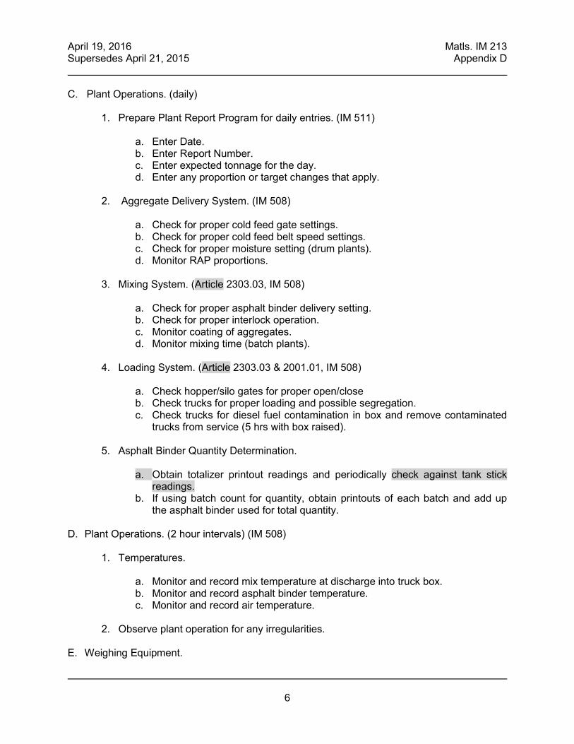
April 19, 2016 Matls. IM 213 Supersedes April 21, 2015 Appendix D
6
C. Plant Operations. (daily)
1. Prepare Plant Report Program for daily entries. (IM 511)
a. Enter Date. b. Enter Report Number. c. Enter expected tonnage for the day. d. Enter any proportion or target changes that apply.
2. Aggregate Delivery System. (IM 508)
a. Check for proper cold feed gate settings. b. Check for proper cold feed belt speed settings. c. Check for proper moisture setting (drum plants). d. Monitor RAP proportions.
3. Mixing System. (Article 2303.03, IM 508)
a. Check for proper asphalt binder delivery setting. b. Check for proper interlock operation. c. Monitor coating of aggregates. d. Monitor mixing time (batch plants).
4. Loading System. (Article 2303.03 & 2001.01, IM 508)
a. Check hopper/silo gates for proper open/close b. Check trucks for proper loading and possible segregation. c. Check trucks for diesel fuel contamination in box and remove contaminated
trucks from service (5 hrs with box raised).
5. Asphalt Binder Quantity Determination.
a. Obtain totalizer printout readings and periodically check against tank stick readings.
b. If using batch count for quantity, obtain printouts of each batch and add up the asphalt binder used for total quantity.
D. Plant Operations. (2 hour intervals) (IM 508)
1. Temperatures.
a. Monitor and record mix temperature at discharge into truck box. b. Monitor and record asphalt binder temperature. c. Monitor and record air temperature.
2. Observe plant operation for any irregularities.
E. Weighing Equipment.

April 19, 2016 Matls. IM 213 Supersedes April 21, 2015 Appendix D
7
1. Proportioning scales (batch plants). (min. 1/day) (Articles 2001.07 & 2001.20)
(IM 508) a. Perform sensitivity checks of scales. b. Check for interference at scale pivot points.
2. Pay Quantity Scales. (min. 1/day) (Articles 2001.07 & 2001.20, IM 508)
a. Regularly perform check weighing comparisons with a certified scale as necessary. (min. 1st day and one additional if >5000 tons, and as directed by Engineer)
b. Perform sensitivity checks of scales. c. Check for interference at scale pivot points. d. Perform verification weighing (truck platform scales).
3. Weigh Belts. (daily)
a. Check weigh belt for excess clinging fines that effects speed reading. b. Check weigh belt for interference at bridge pivot points. c. Check for proper span setting.
4. Enter scale checks in Plant Report Program. (daily) F. Plant Sampling. (daily) (Article 2303.04, IM 204 & 511)
1. Obtain cold-feed gradation samples as directed by Contracting Authority personnel
per IM 301and IM 204.
2. Obtain asphalt binder samples as directed by Contracting Authority personnel per IM 323 and IM 204.
3. Obtain cold-feed moisture samples at a minimum of every ½ day (drum mix plants).
G. Field Sampling (if not performed by others). (daily) (Article 2303.04, IM 204 & 511)
1. Obtain uncompacted mix random samples as directed by Contracting Authority
personnel, and identify time, station, lift and side. 2. Obtain compacted mix core random samples as directed by Contracting Authority
personnel.
H. Testing. (daily) (Article 2303.04, IM 204 & 511)
1. Field cores.
a. Provide properly calibrated equipment for Contracting Authority technician’s use.
b. Obtain and record core location station and offset information. c. Obtain copy of core thickness measurements from Contracting Authority
Technician.

April 19, 2016 Matls. IM 213 Supersedes April 21, 2015 Appendix D
8
d. Obtain copy of core weights from Contracting Authority technician. e. Record weights and thickness in Plant Report Program.
2. Uncompacted mix.
a. Properly store Contracting Authority secured portion of paired sample. b. Split Contractor half of paired sample into test portions as per IM 357. c. Perform gyratory compaction as per IM 325G. d. Perform bulk specific gravity test of laboratory-compacted specimen as per
IM 321. e. Perform maximum specific gravity test as per IM 350. f. Enter test data into Plant Report Program. g. Submit secured samples to DOT District Lab.
3. Aggregate.
a. Split one sample each day as directed by Contracting Authority personnel
and provide half for testing by Contracting Authority. b. Perform gradation analysis as per IM 302 and enter weights into Plant Report
Program. c. Perform moisture tests and produce results upon request.
4. Testing Lab Qualification. (as needed) (IM 208 & 511) a. Record all HMA sample validations with DOT on form 235. b. Document corrective actions taken when not correlating. c. Document all test equipment calibrations. d. Update IM’s, test procedures and specs as required.
I. Documentation. (daily) (Article 2303.04, IM 204, 511 & 508) The Plant Report, Chart, Plant Book, and other HMA worksheets are available on the following website: http://www.iowadot.gov/Construction_Materials/hma.html
1. Prepare computerized Daily Plant Report. a. Check that all data is correct. b. Check that all data is complete. c. Compute tons of mix used to date. d. Enter mix adjustment data on report. e. Check for spec compliance. f. Immediately report non-complying results. g. Obtain and record mat temperatures and stationing. h. Provide electronic daily Plant Report to DME.
2. Maintain a daily diary of work activity in Plant Report Program.
a. Record weather conditions. b. Record daily high and low temperatures. c. Record sunrise and sunset times.
April 19, 2016 Matls. IM 213 Supersedes April 21, 2015 Appendix D
9
d. Record any interruptions to plant production. e. Record any other significant events.
3. Import daily data into charting program.
4. Enter tack shipment quantities in Plant Report Program.
5. Total all truck tickets delivered to project and deduct any waste to determine HMA
pay quantity. 6. Complete Daily Check List
J. Miscellaneous. (daily) (IM 208 & 511)
1. Clean lab.
2. Back-up computer files.
3. Dispose of samples as directed by District Lab.
4. Clean and maintain lab equipment. K. Independent Assurance Duties. (Every 3 months) (IM 205 & 216)
1. Pick up HMA and aggregate proficiency sample from District Lab.
2. Test aggregate proficiency sample for gradation per IM 302.
3. Test HMA proficiency sample per IM 357, 325G, 321 & 350.
4. Report test results on proficiency samples to Central Materials Office per IM 205. L. Project Duties. (1/project) (IM 508 & 511)
1. Be in possession of appropriate mix design. 2. Be present during plant calibration.
3. Observe scale calibrations.
4. Perform plant site and set-up inspection and fill out Plant Site Inspection List.
5. Set up Plant Report Program and enter all project information to create Project
Master files at beginning of project.
6. Check that release agents used in truck boxes are on the approved list in MAPLE.

April 19, 2016 Matls. IM 213 Supersedes April 21, 2015 Appendix D
10
7. Copy all computer files and provide to the Contracting Authority at completion of project.
8. Copy all paperwork and control charts and provide to the Contracting Authority at
completion of project.

April 19, 2016 Matls. IM 213 Supersedes April 21, 2015 Appendix D
11
PRESTRESS TECHNICIAN DUTIES Duties of the Prestress Technician are detailed in IM 570 and consist of, but are not limited to the following: A. Pre-pour
1. Identify and document materials requiring outside fabrication inspection. 2. Identify potential fabrication or production problems and notify Iowa DOT inspectors. 3. Verify that all materials incorporated meet the requirements of the contract documents. 4. Review concrete placement documents for strand locations. 5. Check tension calculations. 6. Measure elongation and gauge pressure during tensioning. 7. Check hold down and insert locations. 8. Check stress distributions. 9. Check steel reinforcement and placement. 10. Check strand position. 11. Check condition of pallet.
a. Level
b. Holes
c. Gaps
d. Other deformities
12. Determine moisture of aggregates.
13. Check form condition and placement.
a. Oil
b. Line alignment level
c. Tightness
B. Concrete Placement

April 19, 2016 Matls. IM 213 Supersedes April 21, 2015 Appendix D
12
1. Check on use of an approved mix design and batching operations (sequence). 2. Assure appropriate placement and proper vibration techniques. 3. Measure and record concrete temperature. 4. Assure test cylinders are properly made. 5. Assure appropriate finish. 6. Assure appropriate curing operations.
C. Post-pour 1. Check temperature and record during curing process. 2. Assure concrete strength has been met prior to releasing the line. 3. Assure proper detensioning procedure. 4. Check unit for defects and obtain approval for repairs. 5. Identify and store cylinders with the respective units. 6. Check beam ends for fabrication in accordance with the plans. 7. Assure exterior sides of facia beams are grouted. 8. Inspect after patching and desired surfacing. 9. Measure and record overall dimensions of beam. 10. Measure and record camber at release and compare to design camber. 11. Check and/or measure and record lateral sweep before shipping. 12. Assure proper cylinder cure.

April 19, 2016 Matls. IM 213 Supersedes April 21, 2015 Appendix D
13
PROFILOGRAPH TECHNICIAN DUTIES Duties of the Profilograph Technician are detailed in IM 341 and consist of, but are not limited to the following: A. Test pavement and bridge surfaces for ride quality. B. Evaluate the test data.
1. Indentify bumps and dips. 2. Summarize the roughness into segments and sections.
3. Identify the segments for incentive, disincentive, or grind.
4. Retest and evaluated bumps, dips, and must grid segments for specification compliance.
C. Documentation 1. Document the evaluation on a test report. A copy is sent to the Project Engineer, District
Materials Engineer, and Central Materials.
2. Notify the Project Engineer if the daily average profile index exceeds the specification tolerance.
3. Submit the profilograms to the Project Engineer for all areas tested.

April 19, 2016 Matls. IM 213 Supersedes April 21, 2015 Appendix D
14
SOILS TECHNICIAN DUTIES A certified Soils Technician is required for all projects with Compaction with Moisture Control, Compaction with Moisture and Density Control, or Special Compaction of Subgrade (including for Recreation Trails). Refer to contract documents for Contractor QC testing requirements. Duties of the Soils Technician consist of, but are not limited to the following: A. Sampling: Obtain samples at required frequencies per IM 204. B. Proctor Testing C. Other Testing as Required
1. For projects with Compaction with Moisture Control: Determine moisture content per
frequencies in IM 204. 2. For projects with Compaction with Moisture and Density Control or Special Compaction
of Subgrade: Determine moisture content and in-place density per frequencies in IM 204.
D. Sampling & Testing Equipment
1. Clean and check testing sieves for defects. 2. Assure scale accuracy. 3. Check and maintain other testing equipment.
E. Evaluate the test data.
1. For projects with Compaction with Moisture Control: Confirm soils are being placed
within required moisture content range.
2. For projects with Compaction with Moisture and Density Control or Special Compaction of Subgrade: Confirm soils are being placed within required moisture content range and soil is compacted to density equal to or greater than density requirement.
F. Documentation and Communication 1. Document test data. A copy is sent to the Project Engineer.
2. Relay test results to appropriate supervisory personnel.
3. Notify the Project Engineer if any test results do not meet contract requirements and
assure corrective actions are taken.

April 19, 2016 Matls. IM 213 Supersedes April 21, 2015 Appendix D
15
EROSION CONTROL TECHNICIAN DUTIES
Duties of the Erosion Control Technician consist of, but are not limited to the following: A. Carefully review and be familiar with the details in the contract documents.
B. Assign erosion and sediment control monitoring responsibilities to Erosion & Sediment
Control (ESC) Basics trained field staff. C. Review copies of storm water inspection reports. D. Provide input on initial Erosion Control Implementation Plan (ECIP) submittal and ECIP
updates. E. Provide onsite reviews when requested by Contracting Authority or Contractor field staff.


IM 301
SA
MP
LIN
G


April 21, 2015 Matls. IM 301 Supersedes October 18, 2011
1
Office of Construction & Materials
AGGREGATE SAMPLING & MINIMUM SIZE OF SAMPLES FOR SIEVE ANALYSIS
SCOPE This IM sets forth approved sampling methods and the minimum amount of dry materials necessary for the determination of particle size distribution. LOCATION FOR SAMPLING Safety must be foremost when determining sample locations. The Contractor/Producer shall make adequate provisions, satisfactory to the Engineer, for the safety of personnel responsible to obtain representative samples of the aggregate. Provisions shall include guards for moving belts, pulleys, and wheels near the sampling point, and a stable platform with adequate safety rails when sampling is to be done from an elevated location. Stopped belt sampling locations must be equipped with an on-off switch near, and in plain view of the sampling location. This switch, when in the off position, must have full control of the belt.
1. Conveyor Belt/Template Method
A minimum of three locations is required when obtaining a sample using this method. Normally, the belt should be recharged for each location to help assure a representative sample. (Review section titled ‘Sampling Stockpiles For Gradation Confirmation’). The ends of the template should be spaced to yield approximately one third of the total minimum required sample weight. More increments may be needed to achieve the required minimum weight. Stop the belt and insert the template as illustrated. Remove all material from the belt contained within the template. A brush or whisk broom will be useful in capturing the finer particles. The increments are combined together to make one field sample.

April 21, 2015 Matls. IM 301 Supersedes October 18, 2011
2
2. Stream Flow Method
When obtaining a sample by interception of the aggregate stream flow, care must be exercised, so the sampling device (See picture below.) passes quickly through the entire stream flow and does not overflow. At least three separate passes shall be made with the sampling device when obtaining a sample. Each pass is an increment of the sample. This is normally considered to be the best method to obtain a representative sample of coarse aggregate.

April 21, 2015 Matls. IM 301 Supersedes October 18, 2011
3
3. Stockpile Method (for fine aggregate only, or as directed by the District Materials Engineer)
Stockpile sampling of fine aggregate may be accomplished by either using a shovel or a sand probe. When obtaining a field sample by the stockpile method, a minimum of three increments shall be taken at different locations around the stockpile. Avoid sampling in areas prone to segregation, such as along the bottom of cone stockpiles.
NOTE: Stockpile sampling of coarse or combined aggregate should be avoided. If it becomes absolutely necessary to obtain a sample from a production stockpile, consult the District Materials Engineer to help devise an adequate and proper sampling plan.
MECHANICAL SAMPLERS Mechanical or industrial samplers are used to extract samples from many kinds of free-flowing materials. While there are many different sampler designs, they basically function in the same fashion as the methods described above. The design and operation of the sampler eliminates issues inherent with hand sampling methods, especially if the production plant is capable of producing a large volume of material. Mechanical samplers can be installed in chutes or at the end and middle of moving belts. Not only do they facilitate collecting representative samples, they increase the level of safety by minimizing exposure to moving components of the stream flow. The practice of collecting production over a sufficient time to produce a representative sample should also be applied to mechanical samplers. If the mechanical sampling system produces a very large sample, use the reduction methods described in Materials IM 336 or continue correlations until a minimum time period can be established. If a mechanical sampler is newly installed, the sampler gradation should be compared to a manually collected sample with acceptability being IM 216 tolerances. Sampling should be done in collaboration with the production plant personnel. If stop-belt sampling is used for the comparison, controls for the belt will need to be “locked out” by the Producer for both safety and to meet MSHA requirements. SAMPLING STOCKPILES FOR GRADATION CONFIRMATION

April 21, 2015 Matls. IM 301 Supersedes October 18, 2011
4
Stockpile sampling of coarse or mixed coarse and fine aggregate is difficult due to segregation. When sampling to determine gradation compliance of these materials, the Contractor, Producer or Supplier will supply equipment such as a sampling bin or flow-boy to provide a streamflow or stopped conveyor belt sampling location. An end-loader will open the pile to be sampled in at least three locations. One end-loader bucket from each opened area is then placed into the sampling bin and sampled in a manner to assure representation of the entire quantity. Alternately, material from each of the opened areas may be combined in a small stockpile, carefully blended to minimize degradation of the aggregate, and placed into the sampling bin. Avoid obtaining sample increments at the beginning or end of bin discharge due to the natural tendency of segregation through the bin. SHIPPING SAMPLES Transport aggregate samples in bags or other containers constructed to preclude loss or contamination of the sample, or damage to the contents from mishandling during shipment. Shipping containers for aggregate samples shall each have suitable identification attached and enclosed so that field reporting, laboratory logging and testing may be facilitated. SAMPLE SIZES Minimum sample sizes for sieve analysis of aggregates are based on the smallest sieve through which at least 95% of the sample will pass. The following table lists the required minimum field sample and test sample sizes:
SIEVE SIZE FIELD SAMPLE
(lbs/kg) TEST SAMPLE
(gms/kg) 1½ in. 50/23.0 5,000/5.0 ‹1› 1 in. 30/13.5 3,500/3.5 ¾ in. 20/9.0 2,000/2.0 ½ in. 20/9.0 1,500/1.5 ⅜ in. 10/4.5 1,000/1.0 ‹2›
No. 4 sieve 10/4.5 500/0.5 No. 8 sieve 10/4.5 200/0.2
(Products with maximum sizes over 1½ in. (37.5 mm) are normally visually inspected. Contact the appropriate District Materials Engineer.)
(1) When testing 1½” aggregate for Special Backfill, Granular Subbase, or Modified Subbase the minimum test sample is 2500 grams.
(2) When testing fine aggregate with no more than 10% retained on the No. 4 sieve the minimum test sample is 500 grams.

SAMPLE SIZES Source: IM 301 – April 21, 2015
Minimum sample sizes for sieve analysis of aggregates are based on the smallest sieve through which at least 95% of the sample will pass. The following table lists the required minimum field sample and test sample sizes:
SIEVE SIZE FIELD
SAMPLE (lbs/kg)
TEST SAMPLE (gms/kg)
1½ in. 50/23.0 5,000/5.0 (1) 1 in. 30/13.5 3,500/3.5 ¾ in. 20/9.0 2,000/2.0 ½ in. 20/9.0 1,500/1.5 ⅜ in. 10/4.5 1,000/1.0 (2)
No. 4 sieve 10/4.5 500/0.5 No. 8 sieve 10/4.5 200/0.2
(Products with maximum sizes over 1½ in. (37.5 mm) are normally visually inspected. Contact the appropriate District Materials Engineer.) (1) When testing 1½” aggregate for Special Backfill,
Granular Subbase, or Modified Subbase the minimum test sample is 2500 grams.
(2) When testing fine aggregate with no more than 10% retained on the No. 4 sieve the minimum test sample is 500 grams.


IM
302
SIE
VE
AN
AL
YS
IS


April 19, 2016 Matls. IM 302 Supersedes October 18, 2011
1
Office of Construction & Materials
SIEVE ANALYSIS OF AGGREGATES SCOPE This method of test covers the procedure for determination of the particle size distribution of aggregates. PROCEDURE A. Apparatus
1. Balance accurate to within 0.1 percent of the weight (mass) of the sample to be tested. NOTE: The balance shall be reset to zero before each weighing.
2. Sieves with square openings mounted on substantial frames, constructed in such a
manner to prevent loss of material during sieving. Use suitable sieve sizes to furnish the information required by the specifications covering the material to be tested. The woven wire cloth shall conform to AASHTO M-92. This will normally consist of a set of Box Sieves for testing coarse aggregates consisting of the following sizes:
1 ½ in., 1 in., ¾ in., ½ in., ⅜ in., No. 4, and No. 8.
A set of 8 in. Diameter Sieves for testing fine aggregates consisting of the following sizes:
No. 4, No. 8, No. 16, No. 30, No. 50, No.100, No. 200, and Pan.
A set of 12 in. Diameter Sieves may be used for testing fine aggregate or aggregate containing both coarse and fine material.
Figure 1. Box Sieves for testing coarse aggregates.

April 19, 2016 Matls. IM 302 Supersedes October 18, 2011
2
Figure 2. 12 and 8 in. sieves.
3. Mechanical and hand-powered sieve shakers 4. Drying oven or stove 5. Fiber bristle sieve cleaning brush (similar to stencil brush or cropped paintbrush)
B. Test Sample
1. Test samples for sieve analysis shall conform to the sample size for the applicable material as indicated by Materials IM 301.
2. Obtain the sample for sieve analysis (test sample) from the material to be tested (field
sample) by the appropriate method as outlined in Materials IM 336. The test sample shall be approximately of the weight (mass) desired when dry and must be the end result of the reduction. Reduction to an exact predetermined weight (mass) shall not be permitted.
C. Preparation of Sample
1. When a determination of the amount of material passing the No. 200 sieve is required, test the sample according to Materials IM 306, “Determining the Amount of Material Finer Than the No. 200 Sieve”, before completing the sieve analysis. For coarse aggregates with a nominal maximum size greater than ½ in., a single test sample may be used to determine both sieve analysis and the amount passing the No. 200, or separate test samples may be used for Materials IMs 306 and 302.
2. When the absorbed moisture stays essentially the same for different particle sizes the
sample may be sieved at a surface-dry condition (no free water present).

April 19, 2016 Matls. IM 302 Supersedes October 18, 2011
3
3. Samples with a significant amount of material finer than the No. 4 sieve, or highly absorptive coarse aggregates (i.e. lightweight aggregates) which have changes in moisture for different particle sizes, must be dried to a constant weight (mass) before performing sieve analysis.
4. Coated particles may also be a problem. When this condition exists, the dried material
must be washed over the smallest sieve for which there is a specification requirement (usually the No. 8 sieve), and dried again.
5. Recycled Materials: Material from crushed composite (HMA/PC) pavements must be
sieved at a surface-dry condition using no artificial heat. No gradation determination will be made for material finer than the No. 8 sieve. In some instances, larger particles may be coated to the extent that dry sieving will not accurately reflect the true gradation of the material. In these instances, the air-dried sample must be washed over the No. 8 sieve and allowed to come to a surface-dry condition by air-drying.
Note: For material made from crushed PC pavement, determination of the percent
passing the No. 200 sieve may be required.
D. Test Procedure
1. Weigh and record the weight (mass) of the test sample as the Original Dry Mass. (This is the ‘Dry Mass Washed Weight” if tested by Materials IM 306.) 2. Sieve the sample over the required sieves. The sieving operation must be accomplished
by using a lateral and vertical motion of the sieve(s), accompanied by a jarring action, which keeps the sample moving continuously over the surface of the sieve. Do not attempt to turn or manipulate the aggregate particle through the sieve openings by hand.
When using a mechanical sieve shaker, excessive sieving times may result in degradation of the sample.
Method A When testing a sample with a mixture of coarse and fine aggregate (combined aggregate), and sieve overload of the fine aggregate sieves is anticipated, the material finer than the No. 4 may distributed among two or more sets of sieves and each increment recombined for weighing: Method B Alternately, weigh and record the total minus No. 4 material (W1). Reduce the minus No. 4 material through the 1 in. or smaller mechanical splitter to a minimum 500 g. sample size. Weigh and record the selected reduced portion (W2) and place this material into the nest of fine aggregate sieves and continue step 2 (above). The conversion factor is calculated by dividing W1 by W2, and recorded to the nearest 0.0001.

April 19, 2016 Matls. IM 302 Supersedes October 18, 2011
4
NOTE: Method B is recommended when using 8 in. sieves to test the fine aggregate portion of a sample, when overload is anticipated. If using 12 in. sieves and the original test sample is reasonably close to the required weight (mass), overload should not occur. When sieve overload is anticipated on the No. 8 sieve only, sieve the original sample through the No. 8 box sieve before placing the fine portion in the nest of 8 in. round sieves.
3. The sieving operation may be considered complete when not more than 0.5 percent by weight (mass) of the original sample passes any sieve during an additional one minute of hand-sieving. On the No. 4 and larger sieves, limit the amount of material carried on the sieve to a single layer when determining sieving to completion.
When using 8 in. and 12 in. diameter sieves, the weights retained should not exceed the following:
8 in. diameter sieves 12 in. diameter sieves No more than 200 grams No. 4 no more than 850 grams on each sieve No. 8 and smaller no more than 450 grams
If sieving to completion (as described above) is not readily accomplished, reduce the amount of material carried on the sieve.
6. Clean the retained material from each sieve for weighing. Remove as much material as practical without damaging the wire cloth. Particles may be removed most readily from a sieve by inverting the sieve over a pan and tapping the sieve by hand and/or pushing (without force) the particles out of the mesh into the pan. Care must be taken while cleaning the sieves, so no damage occurs to the wire mesh by bending or breaking the wires. A fiber-bristle brush should be used for cleaning the No. 16, No. 30 and No. 50 sieves. When cleaning the No. 100 or No. 200 sieves, a soft fiber bristle brush and gentle tapping may be employed. Avoid excessive force on the wire cloth. If clogging of the mesh occurs on these finer sieves, they should be sent to the District Materials Laboratory for cleaning.
5. Weight the fraction of material retained on each sieve and in the pan, to at least the
nearest 0.5 gram and record. 6. Total the weight (mass) of the material retained on the sieves and in the pan. An
accuracy check must be made comparing the weight (mass) of the material before sieving to the total of the weights (mass) after sieving. The total of the weights retained on the sieves and in the pan must be within 0.5 percent of the weight of the sample before sieving.
When the percent finer than the No. 200 sieve is not determined:
Total X 100 = Tolerance (99.5 to 100.5)
Original Dry Mass
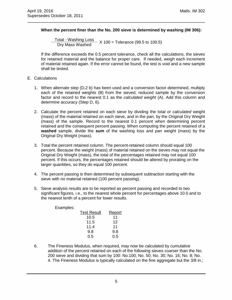
April 19, 2016 Matls. IM 302 Supersedes October 18, 2011
5
When the percent finer than the No. 200 sieve is determined by washing (IM 306):
Total - Washing Loss X 100 = Tolerance (99.5 to 100.5)
Dry Mass Washed If the difference exceeds the 0.5 percent tolerance, check all the calculations, the sieves for retained material and the balance for proper care. If needed, weigh each increment of material retained again. If the error cannot be found, the test is void and a new sample shall be tested.
E. Calculations
1. When alternate step (D,2 b) has been used and a conversion factor determined, multiply each of the retained weights (B) from the sieved, reduced sample by the conversion factor and record to the nearest 0.1 as the calculated weight (A). Add this column and determine accuracy (Step D, 6).
2. Calculate the percent retained on each sieve by dividing the total or calculated weight
(mass) of the material retained on each sieve, and in the pan, by the Original Dry Weight (mass) of the sample. Record to the nearest 0.1 percent when determining percent retained and the consequent percent passing. When computing the percent retained of a washed sample, divide the sum of the washing loss and pan weight (mass) by the Original Dry Weight (mass).
3. Total the percent retained column. The percent-retained column should equal 100 percent. Because the weight (mass) of material retained on the sieves may not equal the Original Dry Weight (mass), the total of the percentages retained may not equal 100 percent. If this occurs, the percentages retained should be altered by prorating on the larger quantities, so they do equal 100 percent.
4. The percent passing is then determined by subsequent subtraction starting with the
sieve with no material retained (100 percent passing).
5. Sieve analysis results are to be reported as percent passing and recorded to two significant figures, i.e., to the nearest whole percent for percentages above 10.0 and to the nearest tenth of a percent for lower results.
Examples: Test Result Report 10.5 11 11.5 12 11.4 11 9.8 9.8 0.5 0.5
6. The Fineness Modulus, when required, may now be calculated by cumulative
addition of the percent retained on each of the following sieves coarser than the No. 200 sieve and dividing that sum by 100: No.100; No. 50; No. 30; No. 16; No. 8; No. 4. The Fineness Modulus is typically calculated on the fine aggregate but the 3/8 in.;

April 19, 2016 Matls. IM 302 Supersedes October 18, 2011
6
3/4 in.; 1 ½ in., and larger, may be used in the calculation (i.e. doubling the previous sieve size).

April 19, 2016 Matls. IM 302 Supersedes October 18, 2011
7
Form 820180ex 11-01
EXAMPLE #1, COARSE AGGREGATE
Lab. No.:
Material: Grad. No.:
Co. & Proj.#:
Producer:
Contractor:
Sampled By: Date:
Sample Loc.:
Original Dry Weight: 5793.0 Total Minus No. 4 (W1):
Dry Weight Washed: Reduced Minus No. 4 (W2)
Washing Loss: Conversion Factor: W1/W2
Calculated Weight (A)=Conversion Factor x (B)
Sieve Size
Reduced
Minus No. 4
Total or Calc.
Weight Retd.
%
Retained
%
Passing
Specs.
1½” 0.0 0.0 100.0
1” 657.0 11.3 88.7
¾” 1068.0 18.4 70.3
½” 1448.0 25.0 (25.1) 45.2
⅜” 1383.0 23.9 (24.0) 21.2
No.4 1082.0 18.7 (18.8) 2.4
No. 8 (B) 141.0 (A) 2.4 0
No.16 (B) (A)
No. 30 (B) (A)
No. 50 (B) (A)
No. 100 (B) (A)
No. 200 (B) (A)
Washing Loss
0 Pan (B) 1.5 (A)
Total 5780.5 99.7 (100.0)
Accuracy Check 99.8
Wash Original Dry Weight: 2571.0
Sample Dry Weight Washed: 2555.0
Washing Loss: 16.0
Sieve Size Weight Retd. % Retd. % Passing Specs.
No. 200 0.8
Washing Loss 16.0
0.8 Pan 4.0
Date Reported: Cert No.:
Tested By:
NOTE: No more than 200 grams should be retained on the 8” sieves. No more than 850 grams should be retained
on the 12” No. 4 sieve, and a maximum of 450 grams on the No. 8 and smaller sieves.
Comments: ________________________________________________________

April 19, 2016 Matls. IM 302 Supersedes October 18, 2011
8
Form 820180ex 11-01
EXAMPLE # 2, FINE AGGREGATE
Lab. No.:
Material: Grad. No.:
Co. & Proj.#:
Producer:
Contractor:
Sampled By: Date:
Sample Loc.:
Original Dry Weight: 594.0 Total Minus No. 4 (W1):
Dry Weight Washed: 591.5 Reduced Minus No. 4 (W2)
Washing Loss: 2.5 Conversion Factor: W1/W2
Calculated Weight (A)=Conversion Factor x (B)
Sieve Size
Reduced
Minus No. 4
Total or Calc.
Weight Retd.
%
Retained
%
Passing
Specs.
1½”
1”
¾”
½”
⅜” 0.0 0.0 100.0
No.4 29.0 4.9 95.1
No. 8 (B) 64.5 (A) 10.9 84.2
No.16 (B) 102.0 (A) 17.2 67.0
No. 30 (B) 181.5 (A) 30.6(30.7) 36.3
No. 50 (B) 154.5 (A) 26.0(26.1) 10.2
No. 100 (B) 51.0 (A) 8.6 1.6
No. 200 (B) 6.0 (A) 1.0 0.6
Washing Loss 2.5
0.6 Pan (B) 1.0 (A)
Total 592.0 99.8(100.0)
Accuracy Check 99.7
Wash Original Dry Weight:
Sample Dry Weight Washed:
Washing Loss:
Sieve Size Weight Retd. % Retd. % Passing Specs.
No. 200
Washing Loss
Pan
Date Reported: Cert No.:
Tested By:
NOTE: No more than 200 grams should be retained on the 8” sieves. No more than 850 grams should be retained on the 12” No. 4 sieve, and a maximum of 450 grams on the No. 8 and smaller sieves.
Comments: ________________________________________________________

April 19, 2016 Matls. IM 302 Supersedes October 18, 2011
9
Form 820180ex 11-01
EXAMPLE #3, COMBINED AGGREGATE, 8” AND BOX SIEVES
Lab. No.:
Material: Grad. No.:
Co. & Proj.#:
Producer:
Contractor:
Sampled By: Date:
Sample Loc.:
Original Dry Weight: 2457.2 Total Minus No. 4 (W1): 2115.7
Dry Weight Washed: 2410.5 Reduced Minus No. 4 (W2) 537.2
Washing Loss: 46.7 Conversion Factor: W1/W2 3.9384
Calculated Weight (A)=Conversion Factor x (B)
Sieve Size
Reduced
Minus No. 4
Total or Calc.
Weight Retd.
%
Retained
%
Passing
Specs.
1½”
1” 0.0 0.0 100.0
¾” 14.6 0.6 99.4
½” 45.9 1.9 97.5
⅜” 81.0 3.3 94.2
No.4 154.0 6.3 87.9
No. 8 57.6 (B) 226.9 (A) 9.2 78.7
No.16 93.0 (B) 366.3 (A) 14.9 63.8
No. 30 178.3 (B) 702.2 (A) 28.6 (28.5) 35.3
No. 50 172.5 (B) 679.4 (A) 27.6 (27.5) 7.8
No. 100 32.7 (B) 128.8 (A) 5.2 2.6
No. 200 3.9 (B) 15.4 (A) 0.6 2.0
Washing Loss 46.7
2.0 Pan 0.8 (B) 3.2 (A)
Total 538.8 2464.4 100.2 (100.0)
Accuracy Check 100.3 100.2
Wash Original Dry Weight:
Sample Dry Weight Washed:
Washing Loss:
Sieve Size Weight Retd. % Retd. % Passing Specs.
No. 200
Washing Loss
Pan
Date Reported: Cert No.:
Tested By:
NOTE: No more than 200 grams should be retained on the 8” sieves. No more than 850 grams should be retained
on the 12” No. 4 sieve, and a maximum of 450 grams on the No. 8 and smaller sieves.
Comments: ________________________________________________________
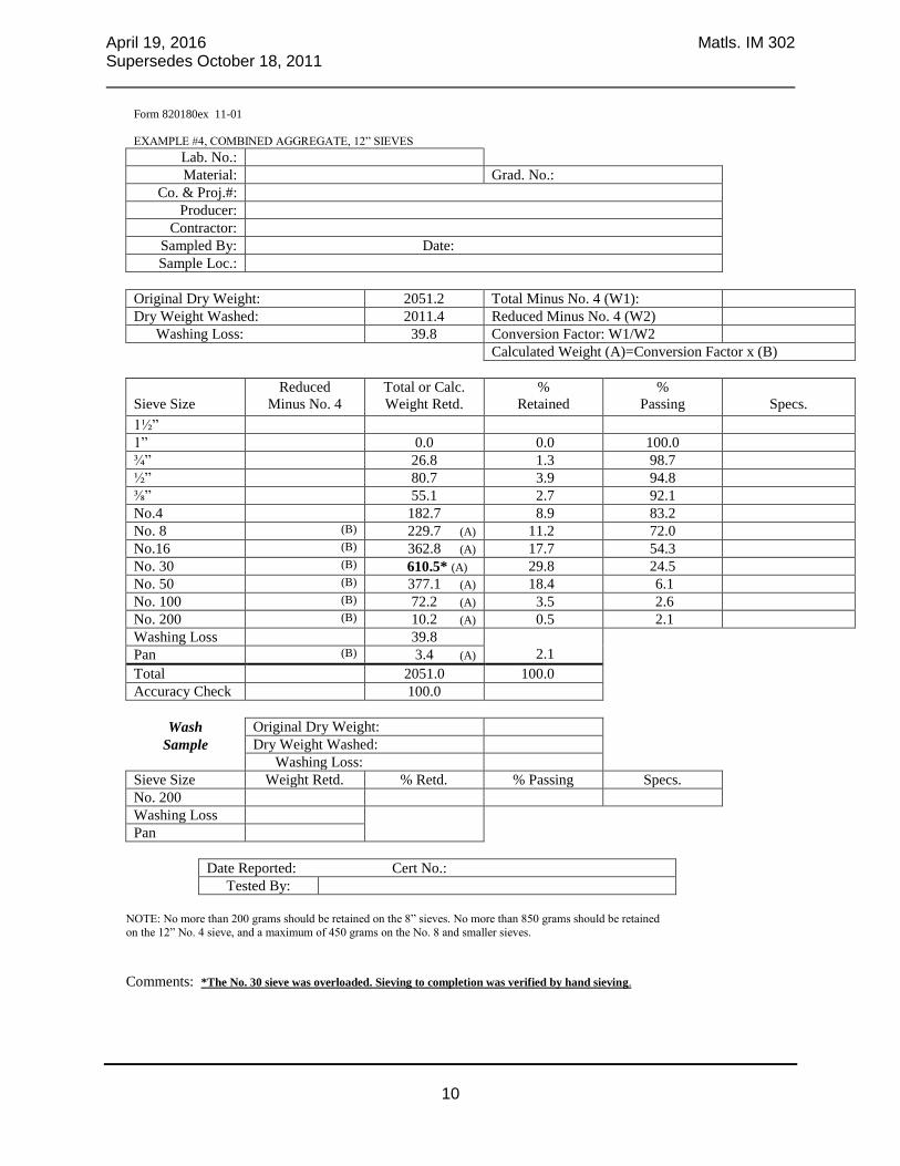
April 19, 2016 Matls. IM 302 Supersedes October 18, 2011
10
Form 820180ex 11-01
EXAMPLE #4, COMBINED AGGREGATE, 12” SIEVES
Lab. No.:
Material: Grad. No.:
Co. & Proj.#:
Producer:
Contractor:
Sampled By: Date:
Sample Loc.:
Original Dry Weight: 2051.2 Total Minus No. 4 (W1):
Dry Weight Washed: 2011.4 Reduced Minus No. 4 (W2)
Washing Loss: 39.8 Conversion Factor: W1/W2
Calculated Weight (A)=Conversion Factor x (B)
Sieve Size
Reduced
Minus No. 4
Total or Calc.
Weight Retd.
%
Retained
%
Passing
Specs.
1½”
1” 0.0 0.0 100.0
¾” 26.8 1.3 98.7
½” 80.7 3.9 94.8
⅜” 55.1 2.7 92.1
No.4 182.7 8.9 83.2
No. 8 (B) 229.7 (A) 11.2 72.0
No.16 (B) 362.8 (A) 17.7 54.3
No. 30 (B) 610.5* (A) 29.8 24.5
No. 50 (B) 377.1 (A) 18.4 6.1
No. 100 (B) 72.2 (A) 3.5 2.6
No. 200 (B) 10.2 (A) 0.5 2.1
Washing Loss 39.8
2.1 Pan (B) 3.4 (A)
Total 2051.0 100.0
Accuracy Check 100.0
Wash Original Dry Weight:
Sample Dry Weight Washed:
Washing Loss:
Sieve Size Weight Retd. % Retd. % Passing Specs.
No. 200
Washing Loss
Pan
Date Reported: Cert No.:
Tested By:
NOTE: No more than 200 grams should be retained on the 8” sieves. No more than 850 grams should be retained
on the 12” No. 4 sieve, and a maximum of 450 grams on the No. 8 and smaller sieves.
Comments: *The No. 30 sieve was overloaded. Sieving to completion was verified by hand sieving.

April 19, 2016 Matls. IM 302 Supersedes October 18, 2011
11
Fineness Modulus Calculation For Concrete Sand (Grad. #1 – Spec. 4110)
AASHTO T27
The Fineness Modulus is simply a calculation based on the ‘cumulative’ percent retained from the sieve analysis sample. Starting with the largest sieve retaining any material, add the cumulative percents retained on each sieve through the No. 100 sieve and divide this total by 100. The result is reported to the nearest 0.01%. Note: The percent retained on the No. 200 sieve is not calculated in determining the Fineness Modulus. Example:
Sieve Percent Retained Cumulative Percent Retained 3/8” 0 0
No. 4 3.6 3.6 No. 8 16.9 20.5
No. 16 19.6 40.1 No. 30 23.4 63.5 No. 50 26.1 89.6 No. 100 9.5 99.1
Total Cumulative Percent Retained = 316.4
316.4 ÷ 100 = 3.16 Fineness Modulus


IM 305
FR
AC
TU
RE
D P
AR
T.


April 20, 2004 Matls. IM 305 New Issue
1
Office of Construction & Materials
****THIS IS A NEW IM. – PLEASE READ CAREFULLY.****
FIELD METHOD TO DETERMINE PERCENTAGE OF FRACTURED PARTICLES IN COARSE AGGREGATE GRAVELS
SCOPE This test method is used for evaluating the crushed content of gravel by determining the amount of fractured particles. For this method, a fractured face is an angular or broken surface caused by mechanical crushing. A face is considered a “fractured face” whenever one-half or more of the surface has been broken, with sharp and well defined edges, when looking directly at the fracture. A fractured particle is a particle having at least one fractured face. PROCEDURE A. Apparatus 1. Sieves - a 3/8 in. (9.5 mm) sieve having wire cloth conforming to AASHTO M-92
2. Oven or hot plate
3. Balance - A balance having a capacity of at least 5000 grams, accurate to 0.5 gram B. Sample
Obtain a representative sample by appropriate methods as detailed in Materials IM 301. The weight of the representative sample after reduction must be large enough to yield a minimum of 2500 grams of material after sieving over a 3/8 in. (9.5 mm) sieve.
C. Sample Preparation
The sample must be sieved on the 3/8 in. (9.5 mm) sieve and the material passing the 3/8 in. (9.5 mm) sieve is discarded.
D. Test Procedure
1. Wash and decant the sample to remove dust from the surface of the aggregate particles.
2. Dry the sample to a constant mass (weight) in an oven at a temperature of 230°F ± 9°F (110°C ± 5°C) or on a hot plate at low heat setting. Cool and weigh total sample to the nearest 0.5 gram and record as: pleiginal SamWt.) of OrDry Mass ( .
3. Spread the sample out on a flat surface. Visually examine the aggregate particles and
remove fractured aggregate particles. 4. Weigh the total amount of fractured particles to the nearest 0.5 gram.

April 20, 2004 Matls. IM 305 New Issue
2
E. Calculations
1. Calculate the percent of fractured particles based upon the total mass (weight) of the sample [plus 3/8 in. (9.5 mm)].
2.
PERCENT FRACTURED PARTICLES =
100ple iginal SamWt.) of OrDry Mass (
rticlesactured PaWt.) of FrDry Mass (

IM
306
FIN
ER
TH
AN
#200


October 20, 2015 Matls. IM 306 Supersedes October 18, 2011
1
Office of Construction & Materials
DETERMINING THE AMOUNT OF MATERIAL FINER THAN THE No. 200 SIEVE IN AGGREGATE
SCOPE This test method outlines the procedure for determining the quantity of material finer than a No. 200 sieve by washing and dry sieving. PROCEDURE A. Apparatus
1. A No. 200 sieve (wash sieve) 2. A wash pan large enough to prevent loss of water and material 3. Oven or drying stove 4. Balance accurate to 0.1 percent of the sample weight 5. A set of 8-in. or 12-in. diameter sieves for dry sieving
B. Test Sample 1. Select the test sample from the material to be tested by an appropriate method as
outlined in Materials IM 336. 2. When determination of specification compliance is needed on each or any of the
following sieves: No. 16, No. 30, No. 50, or No. 100, subject the entire sample to this test procedure.
3. When determination of specification compliance is needed for only the amount of
material finer than the No. 200 sieve, reduce the remaining portion of the field sample from which the original test sample was selected, by the appropriate method as outlined in IM 336. A representative sample, sufficient to yield not less than the appropriate weight of dried material, as shown in the following table shall be selected:

October 20, 2015 Matls. IM 306 Supersedes October 18, 2011
2
Sieve Analysis Sample Weight (grams) Appropriate Minimum (See Materials IM 301) Weight (grams) of Sample
5,000 g 2,500 g 3,500 g 2,500 g 2,000 g 1,000 g 1,500 g * 1,000 g * 500 g * 200 g *
*Use entire sample.
C. Test Procedure
1. Place the sample in the oven at 230˚F or on the stove and dry to a constant weight. Care must be taken in drying the sample to avoid overheating causing the sample to “pop” or “sputter.”
2. Allow the sample to cool, weigh and record as the Original Dry weight. 3. Place the sample in the wash pan and add a sufficient amount of water to cover it. A
detergent, dispersing agent, or other wetting solution may be added to the water to ensure a thorough separation of fine material from the coarser particles.
4. Agitate the sample vigorously using a rotary motion of the pan for five to ten seconds. 5. Pour off the water through the No. 200 wash sieve. When washing samples with a high
silt content, it may be necessary to vibrate or lightly tap the wash sieve in order to keep the mesh open so the water and the minus No. 200 sieve material may pass through freely. Repeat this operation until the wash water appears almost clear.

October 20, 2015 Matls. IM 306 Supersedes October 18, 2011
3
6. Rinse any material retained on the No. 200 sieve back into the sample and decant as much water as possible by carefully pouring the water through the No. 200 sieve.
7. Dry the washed sample, allow to cool, weigh and record as the Dry weight of the washed
sample. 8. When determining only the amount passing the No. 200 sieve, screen the sample over
the No. 8 sieve and discard the retained material. Place the portion of material passing the No. 8 sieve on a nest of sieves including the No. 50, No. 100 and No. 200 sieves and the pan. The sieves larger than the No. 200 sieve are included for protection of the No. 200 sieve. Place the nest of sieves in the mechanical sieve shaker and sieve to completion (normally five minutes or less). Weigh and record only the material retained in the pan.
9. When a complete sieve analysis is required, test the entire sample using the appropriate
method as outlined in IM 302.
D. Calculations
% Passing No. 200 sieve = 100x Weight Dry
Pan LossWashingOriginal


IM
307
SP
EC
IFIC
GR
AV
ITY

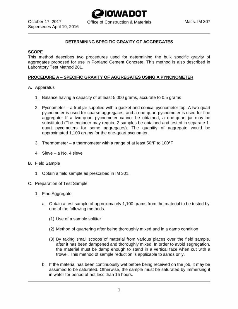
October 17, 2017 Matls. IM 307 Supersedes April 19, 2016
1
Office of Construction & Materials
DETERMINING SPECIFIC GRAVITY OF AGGREGATES SCOPE This method describes two procedures used for determining the bulk specific gravity of aggregates proposed for use in Portland Cement Concrete. This method is also described in Laboratory Test Method 201. PROCEDURE A – SPECIFIC GRAVITY OF AGGREGATES USING A PYNCNOMETER A. Apparatus
1. Balance having a capacity of at least 5,000 grams, accurate to 0.5 grams 2. Pycnometer – a fruit jar supplied with a gasket and conical pycnometer top. A two-quart
pycnometer is used for coarse aggregates, and a one-quart pycnometer is used for fine aggregate. If a two-quart pycnometer cannot be obtained, a one-quart jar may be substituted (The engineer may require 2 samples be obtained and tested in separate 1-quart pycometers for some aggregates). The quantity of aggregate would be approximated 1,100 grams for the one-quart pycnomter.
3. Thermometer – a thermometer with a range of at least 50°F to 100°F 4. Sieve – a No. 4 sieve
B. Field Sample
1. Obtain a field sample as prescribed in IM 301.
C. Preparation of Test Sample
1. Fine Aggregate
a. Obtain a test sample of approximately 1,100 grams from the material to be tested by one of the following methods:
(1) Use of a sample splitter (2) Method of quartering after being thoroughly mixed and in a damp condition (3) By taking small scoops of material from various places over the field sample,
after it has been dampened and thoroughly mixed. In order to avoid segregation, the material must be damp enough to stand in a vertical face when cut with a trowel. This method of sample reduction is applicable to sands only.
b. If the material has been continuously wet before being received on the job, it may be
assumed to be saturated. Otherwise, the sample must be saturated by immersing it in water for period of not less than 15 hours.

October 17, 2017 Matls. IM 307 Supersedes April 19, 2016
2
c. After soaking, pour off the free water, spread the wet sample on a flat, non-
absorbent surface, and allow it to come to a saturated-surface-dry condition by natural evaporation of free moisture. Circulation of air by means of a fan may also be used to attain the surface-dry condition. The sample should be stirred frequently to secure uniform drying.
2. Coarse Aggregate
a. Obtain the test sample as prescribed in IM 336, Methods of Reducing Aggregate Field Samples to Test Samples (See Sections on Quartering or Splitting).
b. Sieve the test sample over the No. 4 sieve. The sample should be of sufficient size
to produce approximately 2,100 grams of material retained on the No. 4 sieve. Discard the material that passes this sieve.
c. Immerse the sample (plus No. 4 sieve size) in water for a period of not less than 15
hours. d. Remove the sample from the water and dry to a saturated surface dry (SSD)
condition by rolling it in a large absorbent cloth until all visible films of water are removed. Wipe the larger particles individually. Place the coarse portion of the sample in a large, flat pan or on a clean hard surface. A moving stream of air by means of fan may be used to assist the drying operation. Take care to avoid evaporation of water from aggregate pores during the operation of surface-drying. (Note: When the surface dry condition is achieved, aggregate particles will have lost the glossy wet appearance and leave no streaks of moisture, but will still have a damp and darkened appearance). Weigh the test sample in the SSD condition. Record this and all subsequent weights to the nearest 0.5 gram.
e. The sample may be considered to be saturated-surface-dry when the particles look comparatively dull as the free moisture is removed from their surfaces. For highly absorptive aggregates, the saturated-surface-dry condition is reached when there is an absence of free moisture.
D. Calibration of Pycnometers
1. Fill the pycnometer jar nearly full of water at the temperature to be used in the actual test, plus or minus 3°F. This may be done either before or after the actual test.
2. Screw the pycnometer top down tightly on the jar and mark the position of the top on the
jar by a scratch or mark on the threaded rim and a scratch in a corresponding position on the jar, which will establish a constant volume.
3. Fill the pycnometer completely by pouring water into the hole of the pycnometer top until
a bead forms above the opening. Immediately wipe the bead of water level with the pycnometer opening. Wipe all other excess moisture from the outside surfaces of the pycnometer. If a bead of water forms at the opening during the final wiping, it should remain for weighing. Weigh the pycnometer to the nearest 0.5-gram.

October 17, 2017 Matls. IM 307 Supersedes April 19, 2016
3
E. Test Procedure
1. Weigh the saturated-surface-dry sample to the nearest 0.5-gram. For ease in calculations, the fine aggregate sample may be brought to exactly 1,000 grams weight, and the coarse aggregate sample may be brought to exactly 2,000 grams weight.
2. Place the sample in the appropriate pycnometer containing approximately two inches of
water. 3. Nearly fill the pycnometer jar with water at the same temperature plus or minus 3°F as
used in the calibration. 4. Screw the cap down into the proper position by lining up the mark on the pycnometer
top and the jar. 5. Entirely fill the pycnometer by adding additional water through the hole in the
pycnometer top. 6. Hold one finger over the hole in the top and gently roll and shake the pycnometer to
remove any trapped air in the sample. 7. When further rolling and shaking brings no more air bubbles to the top, fill, dry and
weigh as in step C3.
F. Calculations
1. Calculate the saturated-surface-dry (SSD) specific gravity to the nearest 0.01 by the following formula:
Bulk Specific Gravity (SSD) = W- S + P
S
Where: S = Weight in grams of aggregate in a saturated-surface-dry condition. P = Weight in grams of the pycnometer filled with water.
W = Weight in grams of the pycnometer containing the sample and sufficient water to fill the remaining space in the pycnometer.
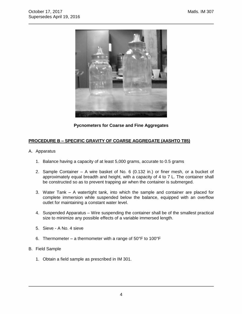
October 17, 2017 Matls. IM 307 Supersedes April 19, 2016
4
Pycnometers for Coarse and Fine Aggregates PROCEDURE B – SPECIFIC GRAVITY OF COARSE AGGREGATE (AASHTO T85) A. Apparatus
1. Balance having a capacity of at least 5,000 grams, accurate to 0.5 grams 2. Sample Container – A wire basket of No. 6 (0.132 in.) or finer mesh, or a bucket of
approximately equal breadth and height, with a capacity of 4 to 7 L. The container shall be constructed so as to prevent trapping air when the container is submerged.
3. Water Tank – A watertight tank, into which the sample and container are placed for
complete immersion while suspended below the balance, equipped with an overflow outlet for maintaining a constant water level.
4. Suspended Apparatus – Wire suspending the container shall be of the smallest practical
size to minimize any possible effects of a variable immersed length. 5. Sieve - A No. 4 sieve 6. Thermometer – a thermometer with a range of 50°F to 100°F
B. Field Sample
1. Obtain a field sample as prescribed in IM 301.
October 17, 2017 Matls. IM 307 Supersedes April 19, 2016
5
C. Preparation of Test Sample
1. Prepare the test sample identical to that described in Procedure A.
D. Test Procedure
1. Weigh the saturated-surface-dry sample to the nearest 0.5-gram. For ease in calculations, the fine aggregate sample may be brought to exactly 1,000 grams weight, and the coarse aggregate sample may be brought to exactly 2,000 grams weight.
2. After weighing, immediately place the saturated-surface-dry sample in the sample
container, remove all entrapped air by shaking the immersed container, and determine its weight in water at 73.4°F ± 3°F. Make sure the water is at a depth sufficient enough to cover the container and sample.
E. Calculations
1. Calculate the saturated-surface-dry (SSD) specific gravity to the nearest 0.01 by the following formula:
Bulk Specific Gravity (SSD) = W- S
S
Where: S = Weight in grams of aggregate in a saturated-surface-dry condition. W = Weight in grams of the saturated-surface-dry sample in water


IM 308
FR
EE
MO
IST
UR
E


October 20, 2015 Matls. IM 308 Supersedes October 19, 2004
1
Office of Construction & Materials
DETERMINING FREE MOISTURE & ABSORPTION OF AGGREGATES
SCOPE This method describes several procedures for determining free moisture and absorption of aggregates. PROCEDURE A - FREE MOISTURE IN AGGREGATES USING A PYCNOMETER A. Apparatus
1. Balance having a capacity of at least 5,000 grams accurate to 0.5 grams 2. Pycnometer - A fruit jar supplied with a gasket and conical pycnometer top. A two-quart
pycnometer is used for coarse aggregates. If a two-quart pycnomter cannot be obtained, a one-quart jar may be substituted (The engineer may require 2 samples be obtained and tested in separate 1-quart pycnometers for some aggregates). The quantity of aggregate would be approximately 1000 grams for the one-quart pycnomter. A one-quart pycnometer is used for fine aggregates.
3. Thermometer -30°F to 120°F thermometer 4. Scoop
B. Field Sample
1. Obtain a field sample as prescribed in IM 301.
C. Preparation of Test Sample
1. Obtain a test sample of about 1000 grams of fine aggregate or about 2000 grams of coarse aggregate by the following method:
Place the field sample on a clean, hard non-absorbent surface. Mix the sample thoroughly,
form a miniature stockpile and obtain small increments of materials from random locations from the stockpile until the desired sample size is obtained. NOTE: The moisture test should be completed as soon as possible after obtaining the field sample to avoid moisture loss due to evaporation.
2. Weigh to the nearest 0.5-gram, a 1,000-gram sample of fine aggregate, or 2000-gram
sample of coarse aggregate. To avoid moisture loss due to evaporation the weighing should be done immediately after obtaining the test sample. Also avoid any excessive manipulation of the aggregate, prior to weighing, which could cause a loss of moisture.
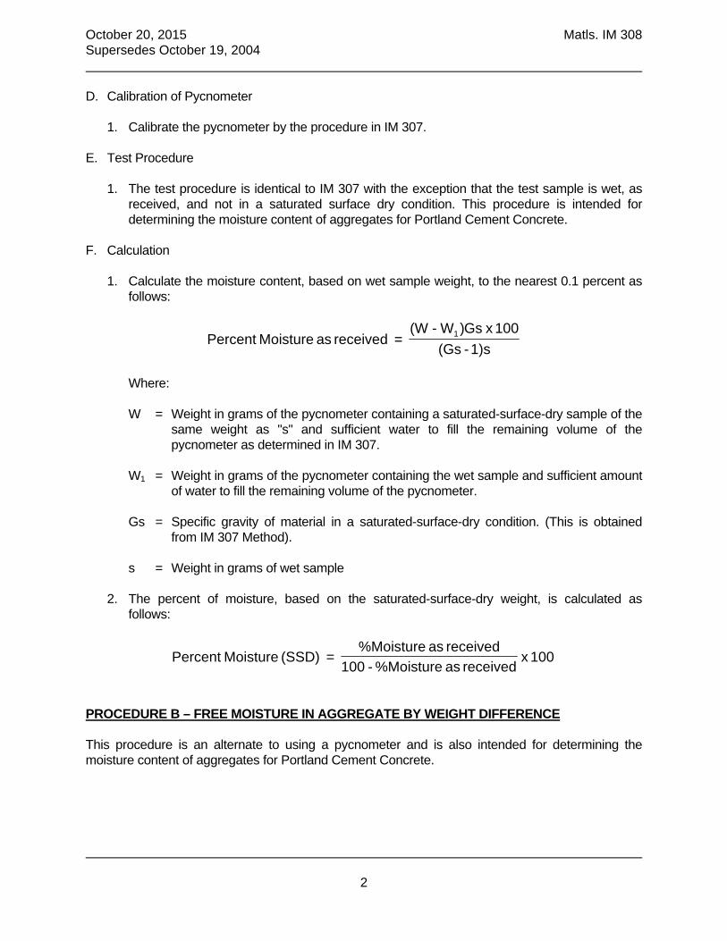
October 20, 2015 Matls. IM 308 Supersedes October 19, 2004
2
D. Calibration of Pycnometer
1. Calibrate the pycnometer by the procedure in IM 307.
E. Test Procedure
1. The test procedure is identical to IM 307 with the exception that the test sample is wet, as received, and not in a saturated surface dry condition. This procedure is intended for determining the moisture content of aggregates for Portland Cement Concrete.
F. Calculation
1. Calculate the moisture content, based on wet sample weight, to the nearest 0.1 percent as follows:
1)s - (Gs
100 x Gs) W- (W = received as Moisture Percent 1
Where: W = Weight in grams of the pycnometer containing a saturated-surface-dry sample of the
same weight as "s" and sufficient water to fill the remaining volume of the pycnometer as determined in IM 307.
W1 = Weight in grams of the pycnometer containing the wet sample and sufficient amount
of water to fill the remaining volume of the pycnometer. Gs = Specific gravity of material in a saturated-surface-dry condition. (This is obtained
from IM 307 Method). s = Weight in grams of wet sample
2. The percent of moisture, based on the saturated-surface-dry weight, is calculated as follows:
100 x received as %Moisture - 100
received as %Moisture = (SSD) Moisture Percent
PROCEDURE B – FREE MOISTURE IN AGGREGATE BY WEIGHT DIFFERENCE This procedure is an alternate to using a pycnometer and is also intended for determining the moisture content of aggregates for Portland Cement Concrete.

October 20, 2015 Matls. IM 308 Supersedes October 19, 2004
3
A. Apparatus
1. Balance having a capacity of at least 5,000 grams and accurate to 0.5 gram
B. Preparation of Sample
1. Prepare the test sample identical to that described in Procedure A.
C. Test Procedure
1. Bring the weighed wet sample to a saturated-surface-dry condition in the manner described in Materials IM 307 and weigh to the nearest 0.5 gram.
D. Calculation
1. Calculate the moisture content, based on wet weight, to the nearest 0.1 percent as follows:
100x received asWeight
SSDWeight - received asWeight isturePercent Mo
A negative result is due to absorption of the aggregate rather than free moisture.
2. The percent of moisture, based on saturated-surface-dry weight, is calculated to the nearest
0.1 percent as follows:
100x received asght by wet wei Moisture% - 100
received as Moisture% (SSD) isturePercent Mo
or
100x dry weight-surface-Saturated
dry weight-surface-Saturated - Wet weight (SSD) isturePercent Mo
PROCEDURE C - WATER ABSORPTION IN AGGREGATE This procedure is used for determining absorption of aggregates for use in asphaltic concrete as well as determining specification compliance for absorption. A. Apparatus
1. Balance having the capacity of at least 5,000 grams and accurate to 0.5 gram 2. Oven or hot plate

October 20, 2015 Matls. IM 308 Supersedes October 19, 2004
4
B. Preparation of Sample
1. Obtain a test sample of at least 1,000 grams of fine aggregate and 2,000 grams of coarse aggregate by following the appropriate procedure outlined in IM 307.
2. When the sample is not in a saturated condition it must be immersed in water at room
temperature for a minimum of 15 hours before continuing with the test. 3. Allow the saturated sample to attain a surface-dry condition by following the procedure in IM
307.
C. Test Procedure
1. Weigh the saturated, surface-dry sample to the nearest 0.5 gram. 2. Dry the sample in the oven or on the hot plate or stove to a constant weight. 3. Allow the sample to cool and weigh to the nearest 0.5 gram.
D. Calculation
1. The percent absorption, based on the oven dry weight is calculated to the nearest 0.01 percent as follows:
Percent Absorption =
100x dry weight Oven
dry weight Oven - dry weight-surface-Saturated

IM
336
RE
DU
CIN
G


April 18, 2017 Matls. IM 336 Supersedes October 20, 2015
1
Office of Construction & Materials
REDUCING AGGREGATE FIELD SAMPLES TO TEST SAMPLES SCOPE This method outlines the proper procedure for reducing an aggregate sample to the proper test sample size. PROCEDURE The sample for testing should be approximately of the weight desired, conforming to the sample size for the material as indicated by Office of Materials IM 301. The test sample must be the end result of the sample reduction method. Do not attempt to select a sample to an exact predetermined weight. I. SPLITTING METHOD
A. Apparatus
1. Sample splitter (conforming to equipment requirements of AASHTO T248-95). 2. Three catch pans 3. Wide, flat-edged scoop
B. Sample Preparation
1. The sample shall be dry enough to allow free flow of the aggregate through the chutes.
Note: A preliminary reduction of fine aggregate in a damp condition may be made using
the 2-inch riffle chute splitter. The resultant sample size shall be not less than 5,000 grams.
C. Test Procedure
1. Place the field sample on a hard, clean surface, such as a counter-top, concrete
floor, or in a large, flat pan. 2. Thoroughly mix the field sample until it appears homogenous. 3. Place a catch pan under the chutes on each side of the splitter. 4. Place increments of the field sample on the wide, flat-edged scoop and uniformly
distribute it from edge to edge, so when it is introduced into the chutes, approximately equal amounts will flow through each chute.
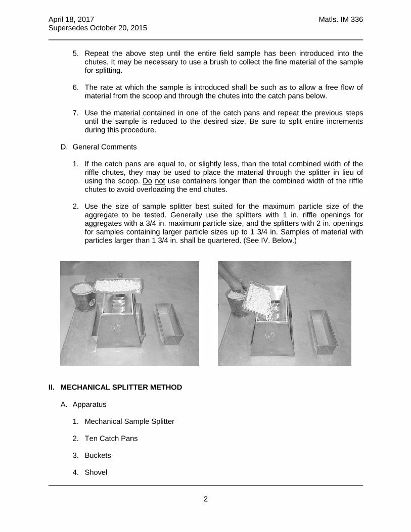
April 18, 2017 Matls. IM 336 Supersedes October 20, 2015
2
5. Repeat the above step until the entire field sample has been introduced into the chutes. It may be necessary to use a brush to collect the fine material of the sample for splitting.
6. The rate at which the sample is introduced shall be such as to allow a free flow of
material from the scoop and through the chutes into the catch pans below. 7. Use the material contained in one of the catch pans and repeat the previous steps
until the sample is reduced to the desired size. Be sure to split entire increments during this procedure.
D. General Comments
1. If the catch pans are equal to, or slightly less, than the total combined width of the riffle chutes, they may be used to place the material through the splitter in lieu of using the scoop. Do not use containers longer than the combined width of the riffle chutes to avoid overloading the end chutes.
2. Use the size of sample splitter best suited for the maximum particle size of the
aggregate to be tested. Generally use the splitters with 1 in. riffle openings for aggregates with a 3/4 in. maximum particle size, and the splitters with 2 in. openings for samples containing larger particle sizes up to 1 3/4 in. Samples of material with particles larger than 1 3/4 in. shall be quartered. (See IV. Below.)
II. MECHANICAL SPLITTER METHOD
A. Apparatus
1. Mechanical Sample Splitter 2. Ten Catch Pans 3. Buckets 4. Shovel

April 18, 2017 Matls. IM 336 Supersedes October 20, 2015
3
B. Sample Preparation
1. The sample shall be dry enough to allow free flow of the aggregate through the chutes.
C. Test Procedure
1. Place the ten small pans of the splitter in the appropriate area of the splitter. 2. Place the entire field sample in buckets. Turn on the splitter and pour material slowly
into the top of the hopper. 3. Complete the pouring of the entire field sample into the hopper (catch pans will hold
one bag without overflowing). If more than one bag is used, you will have to pour each catch pan into separate, larger containers and then resume splitting. It may be necessary to use a brush to collect the fine material of the sample.
4. Use all of the material contained in one or more of the catch pans to obtain the
desired size.
D. General Comments: This method of sample reduction is typically not a field method but intended for larger, laboratory- scale samples.
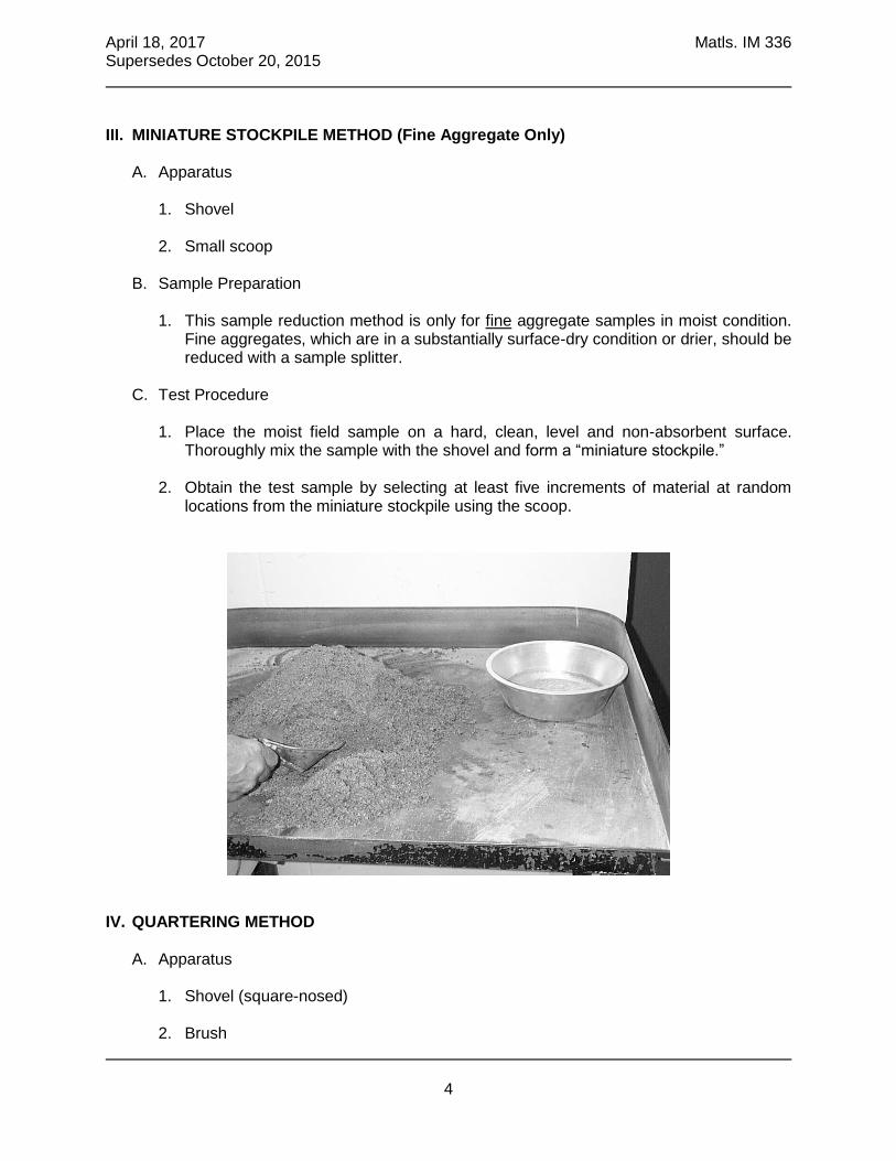
April 18, 2017 Matls. IM 336 Supersedes October 20, 2015
4
III. MINIATURE STOCKPILE METHOD (Fine Aggregate Only)
A. Apparatus
1. Shovel 2. Small scoop
B. Sample Preparation
1. This sample reduction method is only for fine aggregate samples in moist condition. Fine aggregates, which are in a substantially surface-dry condition or drier, should be reduced with a sample splitter.
C. Test Procedure
1. Place the moist field sample on a hard, clean, level and non-absorbent surface. Thoroughly mix the sample with the shovel and form a “miniature stockpile.”
2. Obtain the test sample by selecting at least five increments of material at random
locations from the miniature stockpile using the scoop.
IV. QUARTERING METHOD
A. Apparatus
1. Shovel (square-nosed) 2. Brush
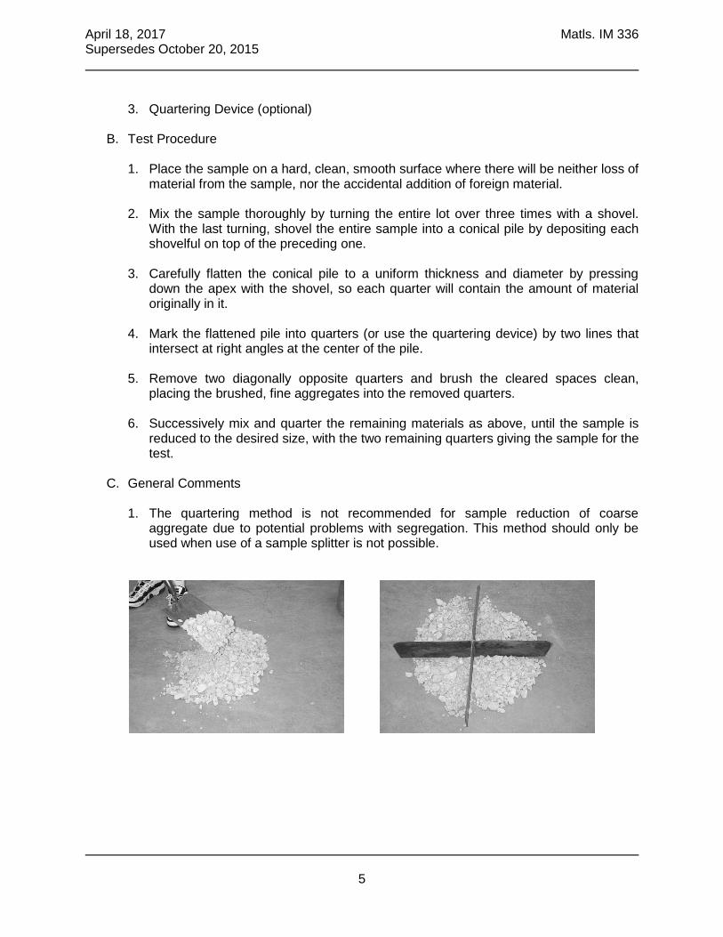
April 18, 2017 Matls. IM 336 Supersedes October 20, 2015
5
3. Quartering Device (optional)
B. Test Procedure 1. Place the sample on a hard, clean, smooth surface where there will be neither loss of
material from the sample, nor the accidental addition of foreign material. 2. Mix the sample thoroughly by turning the entire lot over three times with a shovel.
With the last turning, shovel the entire sample into a conical pile by depositing each shovelful on top of the preceding one.
3. Carefully flatten the conical pile to a uniform thickness and diameter by pressing
down the apex with the shovel, so each quarter will contain the amount of material originally in it.
4. Mark the flattened pile into quarters (or use the quartering device) by two lines that
intersect at right angles at the center of the pile. 5. Remove two diagonally opposite quarters and brush the cleared spaces clean,
placing the brushed, fine aggregates into the removed quarters. 6. Successively mix and quarter the remaining materials as above, until the sample is
reduced to the desired size, with the two remaining quarters giving the sample for the test.
C. General Comments
1. The quartering method is not recommended for sample reduction of coarse aggregate due to potential problems with segregation. This method should only be used when use of a sample splitter is not possible.


IM 344
SH
AL
E - F
INE


October 20, 2015 Matls. IM 344 Supersedes October 19, 2004
1
Office of Construction & Materials
DETERMINING THE AMOUNT OF SHALE IN FINE AGGREGATE SCOPE This test method covers the procedure for the approximate determination of the shale content in fine aggregate. This test method is the field procedure for Laboratory Test Method 209. PROCEDURE A. Apparatus
1. Balance having a capacity of not less than 1,000 g and sensitive to at least 0.1 g 2. A strainer with openings smaller than No. 16 sieve 3. Two bowls of sufficient capacity 4. A solution of zinc chloride (ZnCl2) having a specific gravity between 1.950 and 1.999 at
70°F
NOTE: To prepare one gallon of solution, slowly add 5670 g of technical grade zinc chloride to 2248 g of water with constant stirring. The zinc chloride is added slowly to all the needed water to avoid generating excessive heat during the dissolving process. When all zinc chloride is in solution, cool to 70°F and measure specific gravity with a hydrometer. If the sp. gr. is below 1.95, add zinc chloride in 227 g. increments until the sp. gr. of the solution is at least 1.95 at 70°F. It may be necessary to heat the original solution slightly in order to dissolve additional zinc chloride in a reasonable time. CAUTION: There is no particular hazard from the fumes of the zinc chloride solution, but protective clothing should be worn. This includes gloves, goggles, and face shield. Mix in a well-ventilated area.
5. Drying oven or hot plate 6. Mixing spoon
B. Sample Preparation
1. Select a representative sample by appropriate methods detailed in Materials IM 301 and 336. The weight of the representative sample shall be large enough to yield at least 500 grams of dry material passing the No. 4 sieve.
2. Sieve the representative sample over the No. 4 sieve unless the material is Fine
Aggregate for use in PC Concrete. In this case, any material retained on the No. 4 sieve is also part of the test sample.
3. Dry the test sample to a constant weight, allow to cool, weigh, and record as the Original

October 20, 2015 Matls. IM 344 Supersedes October 19, 2004
2
Dry Weight of the Test Sample. 4. Sieve the test sample over the No.16 sieve. Discard the material passing this sieve and
subject the test sample to the test procedure.
NOTE: The test sample may be accumulated from a completed sieve analysis. This would include the material retained on the No. 8 and No.16 sieves, as well as any material retained on the No. 4 sieve if the intended use is PC Concrete. The Original Dry weight of the test sample would then be the difference between the Original Dry Weight of the sieve analysis sample and the total of the weights retained on and above the No. 4 sieve. (The test sample weight of Fine Aggregate for PC Concrete would be the Original Dry weight of the sieve analysis sample.)
C. Test Procedure
1. Pour the zinc chloride solution into a mixing bowl until the volume of the liquid is at least 3 times the absolute volume of aggregate.
2. Stir the fine aggregate sample into the solution until all particles are coated. 3. Pour the liquid off into a second container, passing it through the strainer. Make sure
that only the floating pieces are poured off and that none of the fine aggregate is decanted onto the skimmer.
4. Return to the first container the liquid that has been collected in the second container
and after further agitation of the sample by stirring, repeat the decanting process just described until the sample is free of floating pieces.
5. Thoroughly wash the removed particles in the strainer to remove the zinc chloride. Dry to
a constant weight in an oven at a temperature of 230 ± 9°F or on a hot plate at a low heat setting. Weigh to the nearest 0.1 g.
D. Calculations
1. Calculate the percentage of shale (and other low specific gravity materials) by the following formula:
100x Sample Analysis Sieve Original ofWeight Dry *
(Shale) Particles DecantedWashed ofWeight Dry Shale %
*This weight includes the material passing the No. 16 sieve and represents the total sample weight of the fine aggregate. Report the result to the nearest 0.1 percent.

IM
368
CL
AY
&F
RIA
BL
E

April 16, 2013 Matls. IM 368 Supersedes April 17, 2007
1
Office of Construction & Materials
DETERMINING THE AMOUNT OF CLAY LUMPS & FRIABLE PARTICLES IN COARSE AGGREGATE
SCOPE This method of test covers the procedure for the determination of clay lumps and friable particles in coarse aggregates. Clay lumps and friable particles are objectionable materials in the aggregate due to contamination at the time the deposit was formed, at the time of quarrying, or at the time of hauling and handling. Clay lumps and friable particles are considered any agglomerated or soft particles retained on the #4 sieve and greater, and will include such terms as mud and clay balls. Method A or Method B may be used to evaluate either stream flow or stock pile samples. The Engineer shall determine the method most appropriate for individual sources. If a sample does not meet specification limits for either test method, the sample is considered non-compliant. PROCEDURE A. Apparatus
1. Balance - A balance having a capacity of at least 5000 grams, accurate to 0.5 gram. 2. Oven capable of maintaining temperature of 110 ± 5°C (230 ± 9°F) or hot plate used at a
reduced temperature, and capable of providing a uniform heat until sample has dried to a constant weight.
3. Containers - Containers of a size and shape that will permit the spreading of the sample
on the bottom in a thin layer. 4. Sieves - Sieves conforming to AASHTO M92, wire cloth sieves for testing purposes.
B. Sample
1. Select a representative sample of material retained on the 4.75-mm (No. 4) sieve that will weigh at least 3000 grams.
METHOD A (Field or Hand Pick Test Method) C. Test Procedure
1. Separate clay lumps and friable particles from the test sample by hand picking. The sample may be wetted and decanted if this aids identification. Oven-dry the clay lumps and friable particles to a constant weight.

April 16, 2013 Matls. IM 368 Supersedes April 17, 2007
2
2. Allow the clay lumps and friable particles to cool and determine the dry weight (L). 3. Dry the test sample to a constant weight. 4. Allow to cool and determine the dry weight (W).
D. Calculation
Percent of clay lumps and friable particles (P) = 100 X L/(L+W) Where: P = percent of clay lumps and friable particles L = dry weight of clay lumps and friable particles W = dry weight of test sample
METHOD B (Laboratory Test Method) E. Test Procedure
1. Wash over No. 4 (75-m) sieve. 2. Oven-dry for at least 16 hours at a temperature of 230 9F (110 5 C) 3. Allow sample to cool and determine the dry weight (W). 4. Spread sample in a thin layer on the bottom of the container, cover it with water and
allow it to soak for a period of 24 4 hours. 5. After soaking period any particles that can be broken with fingers into fines removable by
wet sieving over the No. 8 (2.36-mm) sieve shall be classified as clay lumps or friable particles.
NOTE: The breaking of clay lumps and/or friable particles shall be accomplished by squeezing and rolling them between the thumb and forefinger. The fingernails or mechanical tools shall not be used to break up the particles nor shall they be pressed against a hard surface.
6. Wet sieving is to be accomplished by passing water over the sample through the sieve
while manually agitating the sieve, until all undersize has been removed. 7. The retained particles shall then be carefully removed from the sieve and dried at a
temperature of 230 9F (110 5C). 8. Allow sample to cool, and weigh (R).

April 16, 2013 Matls. IM 368 Supersedes April 17, 2007
3
F. Calculation Calculate the percent of clay lumps and friable particles of coarse aggregates as follows:
100
W
RWP
Where: P = Percent of clay lumps and friable particles. W = Dry weight of test sample after washing on the #4 sieve. R = Dry weight of particles retained on the No. 8 (2.36-mm)(wt. of test sample after
removal of clay lumps).


IM
409
SO
UR
CE
AP
PR
OV
AL
S


October 17, 2017 Matls. IM 409 Supersedes October 2, 2015
1
Office of Construction & Materials
SOURCE APPROVALS FOR AGGREGATES GENERAL Written source approval is required for PCC crushed stone, PCC gravel, PCC fine aggregate, and revetment (forms are available at: http://www.iowadot.gov/Construction_Materials/materials_forms.html or in the appendices of this IM). Only those sources, which can provide aggregates consistently compliant with the applicable specification shall be approved. For proportioned aggregates, aggregate sources shall not be blended to produce a single stockpile. An aggregate source is defined by an individual A-number. APPROVAL PROCESS A. A producer request for source approval shall be made, in writing, to the appropriate District
Materials Engineer with a copy to Geology Section, Office of Construction and Materials in Ames, Iowa.
B. Following documentation of the basis of approval (described below), the District Materials
Engineer will respond to the Chief Geologist with supportive evidence and recommendations to:
1. Approve the source 2. Not approve the source, or 3. Request that specific additional information is obtained as a basis for a final decision
C. Upon the signature of the Chief Geologist, the approval will be returned to the District Materials
Engineer who will return the signed document to the aggregate producer. APPROVALS FOR AGGREGATES USED IN PCC
A. Source approvals shall describe, in detail, any physical limitations of the subject source and any special production methods, or restrictions required to produce specification material.
B. Preliminary source approvals may be issued whenever sufficient quality information is
available. This will expedite the development of new sources or ledges by establishing the primary quality level without requiring production material to be available. A final source approval will follow only after adequate amounts of compliant material have been produced. Aggregate producers may quote from ledges with preliminary approvals assuming full responsibility for the timely delivery of compliant materials to the projects in question.
C. A new or updated source approval will be required if the aggregate durability of a quarry ledge changes or a new bed grouping is approved. The source approval remains with the source. Any changes in management of the source may be documented by letter and will be recorded in IM T203, with a copy maintained in the District source files and Geology Section of the Materials Laboratory. Changes to production restrictions, resulting from joint producer/District quality control discussions, may also be documented by letter, which will be signed by the producer and the District Materials Engineer. A copy of this letter will be maintained in the District source file and Geology Section of the Materials Laboratory.
D. For crushed stone, the ledges shall contain no more than 5% noncompliant materials within

October 17, 2017 Matls. IM 409 Supersedes October 20, 2015
2
the approved bedding planes. At least 95% of carbonate coarse aggregate particles produced by crushing rock shall be derived from ledges in which the rock complies with the requirements for the durability class for which it is being produced.
E. When processing coarse aggregate for PCC no material larger than the gradation top size
may be removed from the product unless allowed by the source approval. When processing multiple PCC products simultaneously, crush to 1.5” nominal before fractionating. Removal of other products may be allowed by the District Materials Engineer if the PCC durability meets or exceeds the original full-face Durability Class and the production method is documented in an amended source approval.
F. Limestone and Dolomite sources greater than 100 miles from the nearest Iowa DOT District
Materials Office or area inspection laboratory may not be allowed to furnish aggregate to Iowa DOT projects. These may be considered too distant to provide source monitoring by Department employees as required in Materials IM 209.
APPROVAL PROCEDURES FOR AGGREGATES USED IN PCC The basis of approval shall be by one of three methods or combination of methods:
1. Service History 2. Geologic Correlation 3. Testing
A. Approval by Service History
1. Aggregate will be considered durable when it does not contribute to the premature deterioration in concrete. Durability classes will be assigned on the basis of qualifying performance in air-entrained concrete pavements of appropriate age.
2. Meet the durability requirements of Article 4115.01. B. Approvals by Geologic Correlation
1. Sources may be approved based on geologic correlation to a source with an established service history.
2. Sources may be approved if there is a satisfactory similarity to any approved source with no aggregate-related deterioration as determined by the Department through pavement coring and petrographic examination.
C. Approvals by Chemical & Physical Testing
Aggregate sources without qualifying performance records or satisfactory similarity to any approved source can be provisionally assigned to a Durability Class based on physical and chemical tests meeting the following requirements:
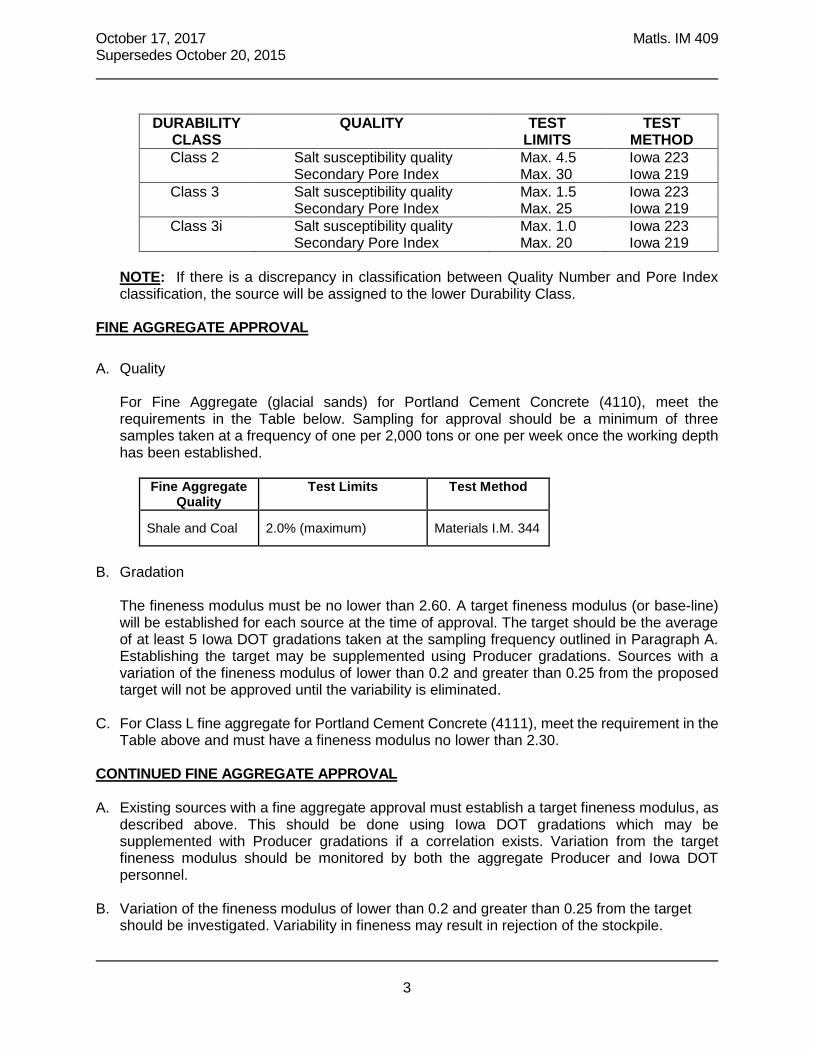
October 17, 2017 Matls. IM 409 Supersedes October 20, 2015
3
DURABILITY
CLASS QUALITY TEST
LIMITS TEST
METHOD Class 2 Salt susceptibility quality Max. 4.5 Iowa 223 Secondary Pore Index Max. 30 Iowa 219 Class 3 Salt susceptibility quality Max. 1.5 Iowa 223 Secondary Pore Index Max. 25 Iowa 219 Class 3i Salt susceptibility quality Max. 1.0 Iowa 223 Secondary Pore Index Max. 20 Iowa 219
NOTE: If there is a discrepancy in classification between Quality Number and Pore Index classification, the source will be assigned to the lower Durability Class.
FINE AGGREGATE APPROVAL
A. Quality
For Fine Aggregate (glacial sands) for Portland Cement Concrete (4110), meet the requirements in the Table below. Sampling for approval should be a minimum of three samples taken at a frequency of one per 2,000 tons or one per week once the working depth has been established.
Fine Aggregate Quality
Test Limits Test Method
Shale and Coal 2.0% (maximum) Materials I.M. 344
B. Gradation
The fineness modulus must be no lower than 2.60. A target fineness modulus (or base-line) will be established for each source at the time of approval. The target should be the average of at least 5 Iowa DOT gradations taken at the sampling frequency outlined in Paragraph A. Establishing the target may be supplemented using Producer gradations. Sources with a variation of the fineness modulus of lower than 0.2 and greater than 0.25 from the proposed target will not be approved until the variability is eliminated.
C. For Class L fine aggregate for Portland Cement Concrete (4111), meet the requirement in the
Table above and must have a fineness modulus no lower than 2.30. CONTINUED FINE AGGREGATE APPROVAL A. Existing sources with a fine aggregate approval must establish a target fineness modulus, as
described above. This should be done using Iowa DOT gradations which may be supplemented with Producer gradations if a correlation exists. Variation from the target fineness modulus should be monitored by both the aggregate Producer and Iowa DOT personnel.
B. Variation of the fineness modulus of lower than 0.2 and greater than 0.25 from the target
should be investigated. Variability in fineness may result in rejection of the stockpile.

October 17, 2017 Matls. IM 409 Supersedes October 20, 2015
4
STONE FOR REVETMENT A. Source approvals, written by the appropriate District Materials Engineer, shall be required for
limestone, dolomite, and quartzite materials. The source approvals shall identify the ledges and the types of revetment for which they are approved.
B. The basis of approval shall be by one of the three methods stipulated in 4130.01:
1. Service History 2. Test Plot Performance 3. Testing
C. All revetment stone from ledges containing conglomerate or breccia, where the performance history has not been established shall be evaluated using a two-year wet test plot before approval. Conglomerate and breccia shall be defined as any rock that contains clasts (i.e., fragments or pieces) of a pre-existing material.
D. The distribution of approvals will include the producer and the Materials Engineer. E. The District may place restrictions on the revetment approval prohibiting winter production of
revetment. F. When subsequent performance indicates the source approval to be in error it shall be modified
or rescinded as necessary.
G. For Erosion stone or stone for Gabion baskets the only requirements are the stone shall not exceed a maximum C-Freeze test limit of 15 when tested in accordance with Iowa 211 Method C and the abrasion maximum shall not exceed 50% when tested in accordance with AASHTO T96.
APPROVAL PROCEDURES A. Approvals by Service History
1. The source approvals shall document the location, age, and sources of all usage forming
the basis of the approvals. 2. The historical usage must conform to the revetment class approved.
B. Approvals by Test Plot Performance 1. Test plots may be of any size that incorporates all beds of the ledge under evaluation. 2. For Class A, B, C, D, and E revetment, the test plots must be constructed in an
environment of wetting and drying cycles combined with seasonal freezing and thawing cycles that meet with the approval of the District Materials Engineer.
3. The test plots will be evaluated after two years and shall have no more than 25% of the
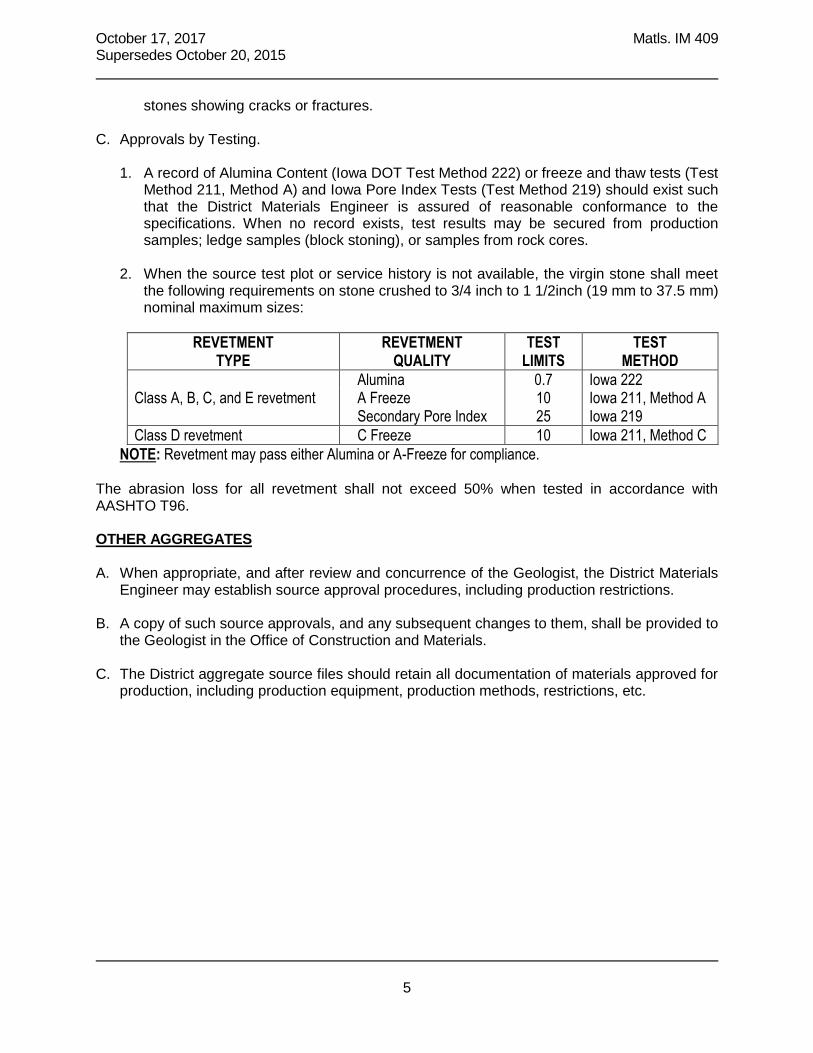
October 17, 2017 Matls. IM 409 Supersedes October 20, 2015
5
stones showing cracks or fractures.
C. Approvals by Testing.
1. A record of Alumina Content (Iowa DOT Test Method 222) or freeze and thaw tests (Test Method 211, Method A) and Iowa Pore Index Tests (Test Method 219) should exist such that the District Materials Engineer is assured of reasonable conformance to the specifications. When no record exists, test results may be secured from production samples; ledge samples (block stoning), or samples from rock cores.
2. When the source test plot or service history is not available, the virgin stone shall meet
the following requirements on stone crushed to 3/4 inch to 1 1/2inch (19 mm to 37.5 mm) nominal maximum sizes:
REVETMENT
TYPE REVETMENT
QUALITY TEST
LIMITS TEST
METHOD
Alumina 0.7 Iowa 222 Class A, B, C, and E revetment A Freeze 10 Iowa 211, Method A Secondary Pore Index 25 Iowa 219
Class D revetment C Freeze 10 Iowa 211, Method C
NOTE: Revetment may pass either Alumina or A-Freeze for compliance. The abrasion loss for all revetment shall not exceed 50% when tested in accordance with AASHTO T96. OTHER AGGREGATES A. When appropriate, and after review and concurrence of the Geologist, the District Materials
Engineer may establish source approval procedures, including production restrictions. B. A copy of such source approvals, and any subsequent changes to them, shall be provided to
the Geologist in the Office of Construction and Materials. C. The District aggregate source files should retain all documentation of materials approved for
production, including production equipment, production methods, restrictions, etc.


IM T
-203
A
GG
RE
GA
TE
SO
UR
CE
S


August 18, 2017 Matls. IM T203
1
Office of Construction & Materials
GENERAL AGGREGATE SOURCE INFORMATION
GENERAL Only those sources which have been sampled or tested within the last ten years are listed. This listing additionally ranks sources in accordance with a frictional classification as defined herein for aggregates used in Hot Mix Asphalt (HMA) construction, durability class for coarse aggregates used in Portland Cement Concrete (PCC) construction, and Approved Fine Aggregate. Upon request, new sources or different combinations of beds within an existing source can be evaluated for classification. These rankings do not in any way waive the normal quality requirements for the particular types of aggregates indicated in contract documents. Aggregate sources are continuously updated and the most current version of this IM can be found on the Materials Approved Product List Enterprise (MAPLE) website at https://maple.iowadot.gov/. Products listed in this document may not always be available. Contact the supplier for availability. PORTLAND CEMENT CONCRETE AGGREGATES Aggregates shall be produced from sources approved in accordance with the requirements of Office of Materials IM 409. The engineer may approve scalping of some portion of the coarser fraction. All aggregates produced and inspected for intended use in contracts under Iowa Department of Transportation Specifications shall be stored in identifiable stockpiles unless they are being delivered as produced. DURABILITY CLASSIFICATION The coarse aggregates have been divided into three classes in accordance with their durability level as determined by performance or laboratory testing. Class 2 durability aggregates will produce no deterioration of pavements of the non-interstate segments of the road system after 15 years and only minimal deterioration in pavements after 20 years. Class 3 durability aggregates will produce no deterioration of pavements of non-interstate segments of the road system after 20 years of age and less than 5% deterioration of the joints after 25 years. Class 3i durability aggregates will produce no deterioration of the interstate road system after 30 years of service and less than 5% deterioration of the joints after 35 years. NOTE: Those sources with a “B” in their durability class designation are approved for 1/2 in. Bridge Deck Overlay/Repair material.

August 18, 2017 Matls. IM T203
2
HOT MIX ASPHALT AGGREGATES Aggregates for HMA construction have been classified into five main functional types in accordance with their frictional characteristics. Those aggregates with the potential to develop the greatest amount of friction under traffic conditions are classified as Type 1 with the potential for friction decreasing as the type number increases. One or more friction types may be specified for use in pavement surface courses. If a type is not specified in the contract documents, Type 5 or better will be acceptable. Tentative bed limitations are shown in this publication. The frictional classification types are listed and defined in order of descending quality as follows. Type 1: Aggregates, which are generally, a heterogeneous combination of minerals with coarse-grained microstructure of very hard particles (generally, a Mohs hardness range of 7 to 9) bonded together by a slightly softer matrix. These aggregates are typified by those developed for and used by the grinding-wheel industry such as calcined bauxite (synthetic) and emery (natural). They are not available from Iowa sources. Due to their high cost, these aggregates would be specified only for use in extremely critical situations. Type 2: Natural aggregates in this class are crushed quartzite and both fine and coarse-grained crushed igneous rocks. The mineral grains in these materials generally have a Mohs hardness range of 5 to 7. Synthetic aggregates in this class are some air-cooled steel furnace slags and others with similar characteristics. For asphalt mixtures, pipestone and sandstone in quartzite may not exceed 5 percent. Type 3: Natural aggregates in this class are crushed gravels. The crushed gravels shall contain 40% or more igneous and metamorphic particles. Synthetic aggregates in this class are the expanded shales with a Los Angeles abrasion loss less than 35 percent. Type 4: Aggregates crushed from dolomitic or limestone ledges in which 80 percent of the grains are 20 microns or larger. The mineral grains in the approved ledges for this classification generally have a Mohs hardness range of 3 to 4. For natural gravels, the Type 5 carbonate (see below) particles, as a fraction of the total material, shall not exceed the non-carbonate particles by more than 20 percent. Type 5: Aggregates crushed from dolomitic or limestone ledges in which 20 percent or more of the grains are 30 microns or smaller.

August 18, 2017 Matls. IM T203
3
SOURCE LISTINGS - Explanation NOTE: - number indicates additional source restrictions (bottom of page) L=limestone (<15% MgO) and D=dolomite (≥15% MgO), defines rock type for L2 surface mix designs. Bed numbers shown for PCC aggregate are those on the formal source approval letter. Beds shown for HMA sources are those which have been used or have potential for use and are of the designated friction type. Frictional Classification - as indicated on page 2 Hot Mix Asphalt - Type A and B Durability Class for Portland Cement Concrete Coarse Aggregate (“B” indicates acceptability for Bridge Deck Overlay/Repair) Fine Aggregate (X=PCC and HMA Approval, H=HMA use only) Source Code Number - Used to identify sources on test requests and for data storage (A-number). Specific Gravity DWU-Determine When Used by Iowa DOT N
BULK DUR FRICT O SSD PCC HMA T CODE OPERATOR SOURCE NAME LOCATION SpGr CA FA A B BEDS E
29 DES MOINES DIST 5 CRUSHED STONE A29002 L&W QUARRIES INC MEDIAPOLIS-LEONARD SE 01 TO71 R04W 2.65 3 4 4 15 L, 1 4 4 15 - 18 L 5 5 20 L A29008 CESSFORD CONST CO NELSON NE 26 TO72 R02W 2.62 3 4 4 21 - 24 4 4 7 - 20 L 4 15 - 24 5 5 24 - 27 L A29012 CESSFORD CONST CO GEODE NE 01 TO69 R05W 4 4 11 - 12 L 5 5 9 - 13 L 4 4 17 L SAND & GRAVEL A29502 CESSFORD CONST CO SPRING GROVE SW 36 TO69 R03W 3 4 4 2.66 X
NOTE 1: AASHTO 57 GRADATION MAXIMUM
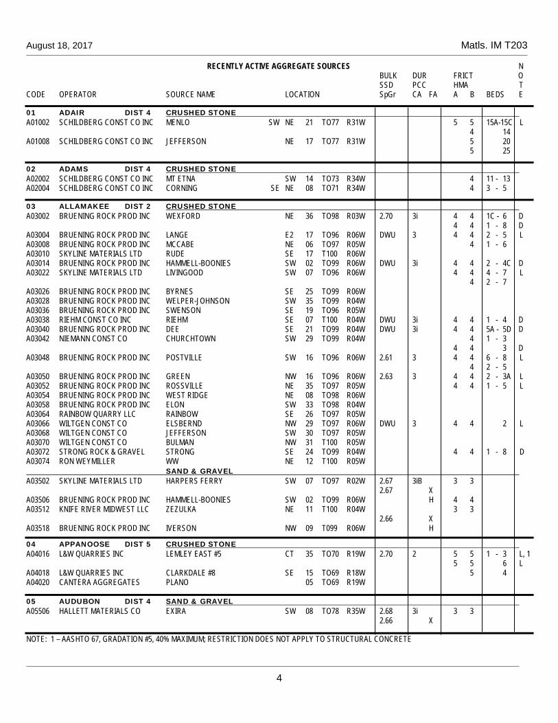
August 18, 2017 Matls. IM T203
RECENTLY ACTIVE AGGREGATE SOURCES N BULK DUR FRICT O SSD PCC HMA T CODE OPERATOR SOURCE NAME LOCATION SpGr CA FA A B BEDS E
4
01 ADAIR DIST 4 CRUSHED STONE A01002 SCHILDBERG CONST CO INC MENLO SW NE 21 TO77 R31W 5 5 15A-15C L 4 14 A01008 SCHILDBERG CONST CO INC JEFFERSON NE 17 TO77 R31W 5 20 5 25
02 ADAMS DIST 4 CRUSHED STONE A02002 SCHILDBERG CONST CO INC MT ETNA SW 14 TO73 R34W 4 11 - 13 A02004 SCHILDBERG CONST CO INC CORNING SE NE 08 TO71 R34W 4 3 - 5
03 ALLAMAKEE DIST 2 CRUSHED STONE A03002 BRUENING ROCK PROD INC WEXFORD NE 36 TO98 R03W 2.70 3i 4 4 1C - 6 D 4 4 1 - 8 D A03004 BRUENING ROCK PROD INC LANGE E2 17 TO96 R06W DWU 3 4 4 2 - 5 L A03008 BRUENING ROCK PROD INC MCCABE NE 06 TO97 R05W 4 1 - 6 A03010 SKYLINE MATERIALS LTD RUDE SE 17 T100 R06W A03014 BRUENING ROCK PROD INC HAMMELL-BOONIES SW 02 TO99 R06W DWU 3i 4 4 2 - 4C D A03022 SKYLINE MATERIALS LTD LIVINGOOD SW 07 TO96 R06W 4 4 4 - 7 L 4 2 - 7 A03026 BRUENING ROCK PROD INC BYRNES SE 25 TO99 R06W A03028 BRUENING ROCK PROD INC WELPER-JOHNSON SW 35 TO99 R04W A03036 BRUENING ROCK PROD INC SWENSON SE 19 TO96 R05W A03038 RIEHM CONST CO INC RIEHM SE 07 T100 R04W DWU 3i 4 4 1 - 4 D A03040 BRUENING ROCK PROD INC DEE SE 21 TO99 R04W DWU 3i 4 4 5A - 5D D A03042 NIEMANN CONST CO CHURCHTOWN SW 29 TO99 R04W 4 1 - 3 4 4 3 D A03048 BRUENING ROCK PROD INC POSTVILLE SW 16 TO96 R06W 2.61 3 4 4 6 - 8 L 4 2 - 5 A03050 BRUENING ROCK PROD INC GREEN NW 16 TO96 R06W 2.63 3 4 4 2 - 3A L A03052 BRUENING ROCK PROD INC ROSSVILLE NE 35 TO97 R05W 4 4 1 - 5 L A03054 BRUENING ROCK PROD INC WEST RIDGE NE 08 TO98 R06W A03058 BRUENING ROCK PROD INC ELON SW 33 TO98 R04W A03064 RAINBOW QUARRY LLC RAINBOW SE 26 TO97 R05W A03066 WILTGEN CONST CO ELSBERND NW 29 TO97 R06W DWU 3 4 4 2 L A03068 WILTGEN CONST CO JEFFERSON SW 30 TO97 R05W A03070 WILTGEN CONST CO BULMAN NW 31 T100 R05W A03072 STRONG ROCK & GRAVEL STRONG SE 24 TO99 R04W 4 4 1 - 8 D A03074 RON WEYMILLER WW NE 12 T100 R05W SAND & GRAVEL A03502 SKYLINE MATERIALS LTD HARPERS FERRY SW 07 TO97 R02W 2.67 3iB 3 3
2.67 X A03506 BRUENING ROCK PROD INC HAMMELL-BOONIES SW 02 TO99 R06W H 4 4 A03512 KNIFE RIVER MIDWEST LLC ZEZULKA NE 11 T100 R04W 3 3 2.66 X A03518 BRUENING ROCK PROD INC IVERSON NW 09 T099 R06W H
04 APPANOOSE DIST 5 CRUSHED STONE A04016 L&W QUARRIES INC LEMLEY EAST #5 CT 35 TO70 R19W 2.70 2 5 5 1 - 3 L, 1 5 5 6 L A04018 L&W QUARRIES INC CLARKDALE #8 SE 15 TO69 R18W 5 4 A04020 CANTERA AGGREGATES PLANO 05 TO69 R19W
05 AUDUBON DIST 4 SAND & GRAVEL A05506 HALLETT MATERIALS CO EXIRA SW 08 TO78 R35W 2.68 3i 3 3 2.66 X
NOTE: 1 – AASHTO 67, GRADATION #5, 40% MAXIMUM; RESTRICTION DOES NOT APPLY TO STRUCTURAL CONCRETE

August 18, 2017 Matls. IM T203
RECENTLY ACTIVE AGGREGATE SOURCES N BULK DUR FRICT O SSD PCC HMA T CODE OPERATOR SOURCE NAME LOCATION SpGr CA FA A B BEDS E
5
06 BENTON DIST 6 CRUSHED STONE A06006 WENDLING QUARRIES INC GARRISON B NE 33 TO85 R11W 2.64 2 4 4 6 - 16 L 5 5 6 - 28 L A06012 COOTS MATERIALS CO INC JABENS SW 07 TO85 R11W DWU 2 5 5 6 - 11 L DWU 2 9 - 12 L 2.63 2 4 4 12 L 4 4 10 - 12 L 4 4 13 - 18 L 4 4 20 - 23 L A06014 WENDLING QUARRIES INC VINTON-MILROY S2 10 TO85 R10W 4 A06016 COOTS MATERIALS CO INC COOTS SW 36 TO86 R11W SAND & GRAVEL A06502 WENDLING QUARRIES INC VINTON-MILROY S2 10 TO85 R10W 2.65 X 4 4 A06504 COOTS MATERIALS CO INC COOTS SAND/VINTON SW 31 TO86 R10W 2.65 X 3 3 A06506 WENDLING QUARRIES INC PORK CHOP CT 11 TO85 R09W DWU X 4 4
07 BLACK HAWK DIST 2 CRUSHED STONE A07004 BMC AGGREGATES LC WATERLOO SOUTH NW 18 TO87 R12W DWU 3 5 5 25 L 4 4 17 - 24 L 4 4 32 - 36 L 5 5 5 - 24 L A07008 BMC AGGREGATES LC MORGAN NE 15 TO89 R12W DWU 3i 4 4 5 L DWU 3i 4 4 top 30’ of 9 D 5 5 1 L 5 1 - 3 5 4A - 4B A07018 BMC AGGREGATES LC RAYMOND-PESKE SW 01 TO88 R12W 2.66 2 4 4 1B - 5 L DWU 2 2 - 5 L DWU 2 3 - 12 L DWU 2 3 - 13 L DWU 2 4 4 2 - 10 D DWU 2 4 4 3 - 10 L 4 4 1B - 10 D 4 4 6 - 10 L A07020 BMC AGGREGATES LC STEINBRON SE 01 TO88 R11W DWU 3 4 4 1B L DWU 2 4 4 1A - 1B L A07022 BMC AGGREGATES LC MESSERLY NE 08 TO90 R14W SAND & GRAVEL A07504 BMC AGGREGATES LC WATERLOO SAND SW 09 TO89 R13W 2.65 X 3 3 A07506 MANATT’S INC ASPRO NW 01 TO88 R13W 2.65 X 4 4 A07508 BMC AGGREGATES LC GILBERTVILLE 16 TO88 R12W DWU 2 4 4 2.65 X A07512 BMC AGGREGATES LC ZEIEN S&G NW 23 TO87 R12W 2.65 X A07518 NIEMANN CONST CO JANESVILLE NE 14 TO90 R14W 2.66 X 3 3
08 BOONE DIST 1 SAND & GRAVEL A08504 STRATFORD GRAVEL INC JENSEN SW 36 TO85 R25W H A08526 STRATFORD GRAVEL INC POWERS 29 TO84 R28W H A08528 STRATFORD GRAVEL INC LEININGER SW 26 TO85 R25W H
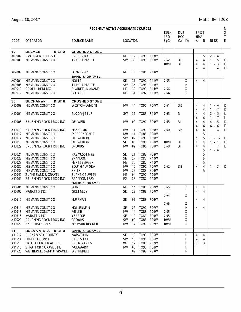
August 18, 2017 Matls. IM T203
RECENTLY ACTIVE AGGREGATE SOURCES N BULK DUR FRICT O SSD PCC HMA T CODE OPERATOR SOURCE NAME LOCATION SpGr CA FA A B BEDS E
6
09 BREMER DIST 2 CRUSHED STONE A09002 BMC AGGREGATES LC FREDERIKA NE 12 TO93 R13W 5 2 - 8 A09006 NIEMANN CONST CO TRIPOLI-PLATTE SW 36 TO93 R13W 2.62 3i 4 4 1 - 5 D DWU 3iB 4 4 1 - 3 D 4 4 4 D A09008 NIEMANN CONST CO DENVER #2 NE 20 TO91 R13W SAND & GRAVEL A09504 NIEMANN CONST CO NOLTE SE 31 TO92 R11W 2.65 X 4 4 A09508 NIEMANN CONST CO TRIPOLI-PLATTE SW 36 TO93 R13W H A09510 CROELL REDI-MIX PLAINFIELD-ADAMS NE 32 TO93 R14W 2.66 X A09512 NIEMANN CONST CO BOEVERS NE 31 TO92 R11W 2.64 X
10 BUCHANAN DIST 6 CRUSHED STONE A10002 NIEMANN CONST CO WESTON-LAMONT NW 14 TO90 R07W 2.61 3iB 4 4 1 - 6 D 4 4 1 - 7 D A10004 NIEMANN CONST CO BLOOM-JESUP SW 32 TO89 R10W 2.63 3 4 4 2 - 5 L 4 4 1 - 7 L A10008 BRUENING ROCK PROD INC OELWEIN NW 02 TO90 R09W 2.65 3i 4 4 4 - 5 D 4 4 4 - 6 D A10010 BRUENING ROCK PROD INC HAZELTON NW 11 TO90 R09W 2.60 3iB 4 4 4 D A10012 NIEMANN CONST CO INDEPENDENCE NW 14 TO88 R09W 5 A10014 NIEMANN CONST CO OELWEIN #1 SW 02 TO90 R09W 5 5 1 - 12 L A10016 NIEMANN CONST CO OELWEIN #2 SE 03 TO90 R09W DWU 3i 4 4 13 - 16 D A10022 BRUENING ROCK PROD INC BROOKS NW 02 TO88 R09W 2.60 3i 4 4 7 L 5 1 - 6 A10024 NIEMANN CONST CO RASMUSSEN #2 SE 21 TO88 R08W 5 A10026 NIEMANN CONST CO BRANDON SE 27 TO87 R10W 5 A10028 NIEMANN CONST CO HERTZBERGER NE 36 TO87 R10W 5 A10030 NIEMANN CONST CO SOUTH AURORA NW 19 TO90 R07W 2.62 3iB 4 4 1 - 3 D A10032 NIEMANN CONST CO SELLS NW 25 TO88 R09W 5 A10040 ZUPKE SAND & GRAVEL ZUPKE-OELWEIN NE 04 TO90 R09W A10042 BRUENING ROCK PROD INC BRANDON I-380 E2 23 TO87 R10W SAND & GRAVEL A10504 NIEMANN CONST CO WARD NE 14 TO90 R07W 2.65 X 4 4 A10506 MANATT’S INC GREENLEY SE 29 TO89 R09W 4 4 2.64 X A10510 NIEMANN CONST CO HUFFMAN SE 02 TO89 R08W 4 4 2.65 X A10514 NIEMANN CONST CO HOLLERMAN SE 26 TO90 R07W H 4 4 A10516 NIEMANN CONST CO MILLER NW 14 TO88 R09W 2.65 X A10518 MANATT’S INC YEAROUS SE 19 TO89 R09W 2.65 X A10520 BRUENING ROCK PROD INC BROOKS SW 02 TO88 R09W DWU X A10522 BARD MATERIALS NIEMANN-DECKER NW 14 TO90 R07W DWU X
11 BUENA VISTA DIST 3 SAND & GRAVEL A11512 BUENA VISTA COUNTY MARATHON SE 19 TO93 R35W H 4 4 A11514 LUNDELL CONST STORM LAKE SW 18 TO90 R36W H 4 4 A11516 HALLETT MATERIALS CO SIOUX RAPIDS W2 12 TO93 R37W H 3 3 A11518 STRATFORD GRAVEL INC MOLGAARD NW 03 TO93 R38W H A11520 WETHERELL SAND & GRAVEL WETHERELL 02 TO93 R38W H

August 18, 2017 Matls. IM T203
RECENTLY ACTIVE AGGREGATE SOURCES N BULK DUR FRICT O SSD PCC HMA T CODE OPERATOR SOURCE NAME LOCATION SpGr CA FA A B BEDS E
7
12 BUTLER DIST 2 CRUSHED STONE A12004 BRUENING ROCK PROD INC LUBBEN NW 25 TO93 R17W 5 1 - 21 A12008 BRUENING ROCK PROD INC FLORRY-STEERE CT 08 TO93 R17W 5 1 - 11 A12010 SKYLINE MATERIALS LTD CLARKSVILLE-ENGLE NE 16 TO92 R15W A12014 NIEMANN CONST CO OLTMANN SE 08 TO91 R16W A12016 BRUENING ROCK PROD INC WIEGMANN-BRISTOW SE 23 TO92 R18W 1 - 11 A12018 BRUENING ROCK PROD INC NEYMEYER SW 28 TO90 R18W A12020 BRUENING ROCK PROD INC BRUNS #2 NW 21 TO91 R18W 5 1 - 5 SAND & GRAVEL A12502 CROELL REDI-MIX CLARKSVILLE NW 01 TO92 R16W 2.67 2 4 4 2.67 X A12516 BRUENING ROCK PROD INC JENSEN S2 18 TO93 R16W H 4 4 A12518 NIEMANN CONST CO SHELL ROCK-ADAMS NE 03 TO91 R15W 3 3 2.66 X A12520 CROELL REDI-MIX PARKERSBURG E2 19 TO90 R16W DWU X A12522 NIEMANN CONST CO HOBSON 34 TO92 R15W 2.66 X
13 CALHOUN DIST 3 SAND & GRAVEL A13502 STRATFORD GRAVEL INC KRUSE NE 26 TO86 R34W H 4 4 A13504 TIEFENTHALER INC JENSEN N2 SW 07 TO86 R34W 2.67 X A13506 MOHR S&G CONST LLC MOHR E2 NW 23 TO86 R34W DWU X A13508 STRATFORD GRAVEL INC PACKER NE 26 TO86 R34W H 3 3
14 CARROLL DIST 3 SAND & GRAVEL A14510 TIEFENTHALER INC LANESBORO NW 17 TO85 R33W 2.72 2 4 4 2.68 X A14514 TIEFENTHALER INC MACKE 06 TO85 R33W 2.69 2 4 4 2.66 X A14516 STRATFORD GRAVEL INC RICHLAND NE 23 TO83 R33W H 4 4 A14518 TIEFENTHALER INC MILLER 21 TO85 R33W DWU 2 DWU X
15 CASS DIST 4 CRUSHED STONE A15004 SCHILDBERG CONST CO INC LEWIS SE 17 TO75 R37W A15008 SCHILDBERG CONST CO INC ATLANTIC MINE SW 13 TO76 R37W 5 25
16 CEDAR DIST 6 CRUSHED STONE A16004 WENDLING QUARRIES INC LOWDEN-SCHNECKLOTH NW 04 TO81 R01W DWU 3i 4 4 1 - 4 D A16006 WENDLING QUARRIES INC STONEMILL SE 14 TO80 R03W DWU 3iB 4 4 4 D A16010 WENDLING QUARRIES INC PEDEN NE 10 TO79 R03W 5 5 A16012 WEBER STONE CO INC ONION GROVE NW 14 TO82 R02W 2.61 3i 4 4 1 - 7 D A16014 WENDLING QUARRIES INC TOWNSEND NW 02 TO79 R02W A16022 WENDLING QUARRIES INC TRICON N2 09 TO82 R04W DWU 3i 4 4 1 D DWU 3i 4 4 1 - 4 D A16026 WENDLING QUARRIES INC PEDEN #2 SW 10 TO79 R03W SAND & GRAVEL A16502 WENDLING QUARRIES INC SHARPLISS NW 12 TO79 R03W 4 4 2.65 X A16506 WEBER STONE CO INC ONION GROVE NE 14 TO82 R02W 2.65 X A16508 WENDLING QUARRIES INC MASSILLON CT 11 TO82 R01W 2.65 X A16510 CROELL REDI-MIX CEDAR BLUFF SW 28 TO81 R04W DWU X

August 18, 2017 Matls. IM T203
RECENTLY ACTIVE AGGREGATE SOURCES N BULK DUR FRICT O SSD PCC HMA T CODE OPERATOR SOURCE NAME LOCATION SpGr CA FA A B BEDS E
8
17 CERRO GORDO DIST 2 CRUSHED STONE A17008 MARTIN MARIETTA PORTLAND WEST NE 19 TO96 R19W 2.75 3iB 4 4 1 - 8 L A17012 MARTIN MARIETTA UBBEN SW 26 TO94 R20W 2.68 2 5 5 3 L 5 5 1 - 3 L A17020 MARTIN MARIETTA MASON CITY NE 29 TO97 R20W DWU 3i 5 5 7 L 2.73 3 5 5 7 - 9 L 4 4 8 - 9 L 1 - 6 A17024 HEARTLAND ASPHALT RIVERVIEW NE 29 TO96 R19W 4 4 1 - 12 L SAND & GRAVEL A17506 KNIFE RIVER MIDWEST LLC NELSON-FORBES SW 27 TO96 R19W H 4 4 A17514 MARTIN MARIETTA HOLCIM SAND NE 19 TO97 R20W DWU 3 3 3 2.65 X A17518 HEARTLAND ASPHALT AIRPORT NE 08 TO96 R21W H 3 3 A17520 NORTH IOWA S&G INC TUTTLE NE 13 TO97 R21W 2.64 X
18 CHEROKEE DIST 3 SAND & GRAVEL A18506 HALLETT MATERIALS CO CHEROKEE SOUTH NE 16 TO91 R40W 2.70 2 3 3 2.69 X A18514 LG EVERIST INC LARRABEE-MONTGOMERY NE2 20 TO93 R39W 2.67 3 3 3 2.63 X A18526 HALLETT MATERIALS CO CHEROKEE NORTH SW 23 TO92 R40W 2.70 3 3 3 2.67 X A18528 LG EVERIST INC WASHTA SW 31 TO90 R41W 2.68 3 3 3 2.64 X A18534 HALLETT MATERIALS CO NELSON CT 23 TO92 R40W 2.67 2 3 3 2.68 X
19 CHICKASAW DIST 2 CRUSHED STONE A19004 BRUENING ROCK PROD INC DEERFIELD-MAHONEY SE 33 TO97 R14W A19008 BRUENING ROCK PROD INC BOICE NE 16 TO95 R14W 5 SAND & GRAVEL A19508 SKYLINE MATERIALS LTD BUSTA SE 23 TO96 R11W 4 4 2.65 X A19512 BRUENING ROCK PROD INC PEARL ROCK SE 31 TO94 R14W 4 4 2.65 X A19514 BRUENING ROCK PROD INC NASHUA SW 33 TO95 R14W 3 3 DWU X A19516 NIEMANN CONST CO REWOLDT NE 25 TO94 R13W 2.64 X A19518 KNIFE RIVER MIDWEST LLC AGGLAND 31 TO96 R12W 2.64 X A19520 NIEMANN CONST CO ROSONKE NE SE 16 TO95 R14W H A19522 CROELL REDI MIX BUCKY’S NW 03 TO95 R11W DWU 3iB 3 3 2.65 X A19524 NIEMANN CONST CO REISNER SE 23 TO96 R11W H
20 CLARKE DIST 5 CRUSHED STONE A20002 SCHILDBERG CONST CO INC OSCEOLA NW 12 TO72 R26W 5 25A -25E 20A-20C 1
NOTE 1: FRICTION TYPE TO BE DETERMINED WHEN USED
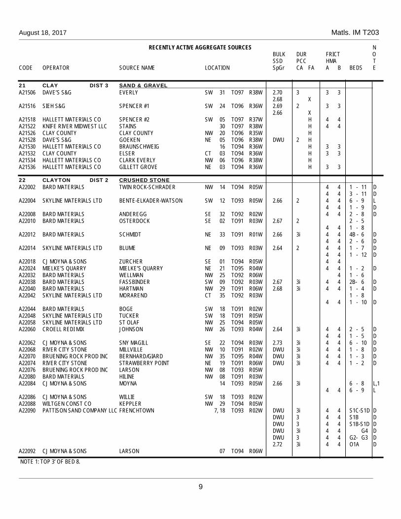
August 18, 2017 Matls. IM T203
RECENTLY ACTIVE AGGREGATE SOURCES N BULK DUR FRICT O SSD PCC HMA T CODE OPERATOR SOURCE NAME LOCATION SpGr CA FA A B BEDS E
9
21 CLAY DIST 3 SAND & GRAVEL A21506 DAVE’S S&G EVERLY SW 31 TO97 R38W 2.70 3 3 3 2.68 X A21516 SIEH S&G SPENCER #1 SW 24 TO96 R36W 2.69 2 3 3 2.66 X A21518 HALLETT MATERIALS CO SPENCER #2 SW 05 TO97 R37W H 4 4 A21522 KNIFE RIVER MIDWEST LLC STAINS 30 TO97 R38W H 4 4 A21526 CLAY COUNTY CLAY COUNTY NW 20 TO96 R35W H A21528 DAVE’S S&G GOEKEN NE 05 TO96 R38W DWU 2 H A21530 HALLETT MATERIALS CO BRAUNSCHWEIG 16 TO94 R36W H 3 3 A21532 CLAY COUNTY ELSER CT 03 TO94 R36W H 3 3 A21534 HALLETT MATERIALS CO CLARK EVERLY NW 06 TO96 R38W H A21536 HALLETT MATERIALS CO GILLETT GROVE NE 03 TO94 R36W H 3 3
22 CLAYTON DIST 2 CRUSHED STONE A22002 BARD MATERIALS TWIN ROCK-SCHRADER NW 14 TO94 R05W 4 4 1 - 11 D 4 4 3 - 11 D A22004 SKYLINE MATERIALS LTD BENTE-ELKADER-WATSON SW 12 TO93 R05W 2.66 2 4 4 6 - 9 L 4 4 1 - 9 D A22008 BARD MATERIALS ANDEREGG SE 32 TO92 R02W 4 4 2 - 8 D A22010 BARD MATERIALS OSTERDOCK SE 02 TO91 R03W 2.67 2 2 - 5 4 4 1 - 8 A22012 BARD MATERIALS SCHMIDT NE 33 TO91 R01W 2.66 3i 4 4 4B - 6 D 4 4 2 - 6 D A22014 SKYLINE MATERIALS LTD BLUME NE 09 TO93 R03W 2.64 2 4 4 1 - 7 D 4 4 1 - 12 D A22018 CJ MOYNA & SONS ZURCHER SE 01 TO94 R05W 4 4 A22024 MIELKE’S QUARRY MIELKE’S QUARRY NE 21 TO95 R04W 4 4 1 - 2 D A22032 BARD MATERIALS WELLMAN NW 25 TO92 R06W 4 1 - 6 A22038 BARD MATERIALS FASSBINDER SW 09 TO92 R03W 2.67 3i 4 4 2B- 6 D A22040 BARD MATERIALS HARTMAN NW 29 TO91 R06W 2.68 3i 4 4 1 - 4 D A22042 SKYLINE MATERIALS LTD MORAREND CT 35 TO92 R03W 1 - 8 4 4 1 - 10 D A22044 BARD MATERIALS BOGE SW 18 TO91 R02W A22048 SKYLINE MATERIALS LTD TUCKER SW 18 TO91 R05W A22058 SKYLINE MATERIALS LTD ST OLAF NW 25 TO94 R05W A22060 CROELL REDI MIX JOHNSON NW 26 TO93 R04W 2.64 3i 4 4 2 - 5 D 4 4 1 - 5 D A22062 CJ MOYNA & SONS SNY MAGILL SE 22 TO94 R03W 2.73 3i 4 4 6 - 10 D A22068 RIVER CITY STONE MILLVILLE NW 10 TO91 R02W DWU 3i 4 4 1 - 8 D A22070 BRUENING ROCK PROD INC BERNHARD/GIARD NW 35 TO95 R04W DWU 3i 4 4 1 - 3 D A22074 RIVER CITY STONE STRAWBERRY POINT NE 19 TO91 R06W DWU 3i 4 4 1 - 2 D A22076 BRUENING ROCK PROD INC LARSON NW 08 TO93 R05W A22080 BARD MATERIALS HILINE NW 08 TO91 R03W A22084 CJ MOYNA & SONS MOYNA 14 TO93 R05W 2.66 3i 6 - 8 L,1 4 4 6 - 9 L A22086 CJ MOYNA & SONS WILLIE SW 18 TO93 R02W A22088 WILTGEN CONST CO KEPPLER NW 29 TO94 R05W A22090 PATTISON SAND COMPANY LLC FRENCHTOWN 7, 18 TO93 R02W DWU 3i 4 4 S1C-S1D D DWU 3 4 4 S1B D DWU 3 4 4 S1B-S1D D DWU 3i 4 4 G4 D DWU 3 4 4 G2- G3 D 2.72 3i 4 4 O1A D A22092 CJ MOYNA & SONS LARSON 07 TO94 R06W
NOTE 1: TOP 3’ OF BED 8.

August 18, 2017 Matls. IM T203
RECENTLY ACTIVE AGGREGATE SOURCES N BULK DUR FRICT O SSD PCC HMA T CODE OPERATOR SOURCE NAME LOCATION SpGr CA FA A B BEDS E
10
22 CLAYTON DIST 2 SAND & GRAVEL A22510 SKYLINE MATERIALS LTD BENTE SE 15 TO93 R05W 2.66 X 4 4 A22520 BARD MATERIALS WELTERLEN SE 32 TO91 R05W 2.65 X A22522 CJ MOYNA & SONS MOYNA 13, 24 TO93 R05W 2.64 X 4 4
23 CLINTON DIST 6 CRUSHED STONE A23002 PRESTON READY MIX ELWOOD-YEAGER NW 08 TO83 R02E DWU 3i 4 4 1 - 2 D A23004 WENDLING QUARRIES INC BEHR SW 02 TO81 R03E 2.61 3i 4 4 1 - 2 D A23006 WENDLING QUARRIES INC SHAFFTON NE 11 TO80 R05E DWU 3i 4 4 16 - 17 D DWU 3i 4 4 17 - 18 D DWU 3i 4 4 18 - 19 D DWU 3i 4 4 20 - 21 D DWU 3 4 4 3 - 14 D DWU 3 4 4 20 - 23 D 4 4 3 - 15 D A23010 WENDLING QUARRIES INC GOOSE LAKE SW 22 TO83 R05E 4 4 1 - 10 D A23012 WENDLING QUARRIES INC TEEDS GROVE SW 03 TO83 R06E 4 A23016 WENDLING QUARRIES INC LYONS NW 18 TO82 R07E 4 A23026 WENDLING QUARRIES INC MILL CREEK NE 22 TO82 R06E 4 A23028 WENDLING QUARRIES INC DELMAR SE 06 TO83 R04E A23030 WENDLING QUARRIES INC EDON VALLEY 04 TO83 R01E A23032 ANDERSON S&G ANDERSON 23 TO81 R03E SAND & GRAVEL A23502 WENDLING QUARRIES INC DOYLE NE 30 TO83 R07E 2.67 X 4 4 A23504 WENDLING QUARRIES INC BEHR SW 02 TO81 R03E 2.68 2 4 4 2.68 X A23506 WENDLING QUARRIES INC SCHNECKLOTH S2 10 TO80 R05E 2.67 X 4 4 A23508 WENDLING QUARRIES INC GATEWAY NE 27 TO81 R06E 2.66 X 4 4 A23510 WENDLING QUARRIES INC SHAFFTON N2 11 TO80 R05E 4 4 2.66 X A23514 ANDERSON S&G ANDERSON NW 23 TO81 R03E 2.68 X A23516 WENDLING QUARRIES INC OLSON NW 23 TO81 R02E DWU X
24 CRAWFORD DIST 3 SAND & GRAVEL A24512 HALLETT MATERIALS CO DUNLAP SE 27 TO82 R41W 2.70 2 3 3 2.66 X
25 DALLAS DIST 4 SAND & GRAVEL A25510 HALLETT MATERIALS CO PERRY NW 01 TO81 R29W 2.70 2 4 4 2.67 X A25514 HALLETT MATERIALS CO BOONEVILLE S2 26 TO78 R26W 2.68 2 3 3 2.66 X A25516 HALLETT MATERIALS CO VAN METER SOUTH 21 22 TO78 R27W 2.68 2 3 3 2.66 X A25518 MARTIN MARIETTA RACCOON RIVER SAND 27 28 TO78 R26W DWU 2 2.65 X
26 DAVIS DIST 5 CRUSHED STONE A26004 DOUDS STONE LLC LEWIS W2 02 TO69 R12W 2.60 3 4 4 1 L 5 5 3 - 7 L 5 3 - 5 4 4 6 - 7 L A26006 DOUDS STONE LLC BROWN SW NW 02 TO69 R12W 2.60 3 4 4 1 L 5 5 3 - 7 L 5 3 - 5 4 4 6 - 7 L SAND & GRAVEL A26502 DOUDS STONE LLC ELDON-FRANKLIN SW 01 TO70 R12W 2.67 X

August 18, 2017 Matls. IM T203
RECENTLY ACTIVE AGGREGATE SOURCES N BULK DUR FRICT O SSD PCC HMA T CODE OPERATOR SOURCE NAME LOCATION SpGr CA FA A B BEDS E
34
SD SOUTH DAKOTA DIST 3 CRUSHED STONE ASD002 LG EVERIST INC DELL RAPIDS E. MINNEHAHA CO SW 10 T104 R49W 2.64 3iB 2 2 ASD004 CONCRETE MATLS CO SIOUX FALLS QUARTZITE 13 T101 R50W 2.64 3iB 2 2 1 ASD006 MYRL & ROY’S PAVING INC EAST SIOUX, MINNEHAHA CO SE 27 T101 R48W DWU 3i 2 2 1 ASD008 SPENCER QUARRIES INC SPENCER, HANSON CO 24 T103 R57W 2 2 ASD010 LG EVERIST INC DELL RAPIDS W. MINNEHAHA CO NW 16 T104 R49W 2.64 3iB 2 2 DIST 3 SAND & GRAVEL ASD502 BOYER SAND AND GRAVEL BOYER, UNION CO 10 TO95 R48W DWU 2 H 4 4 ASD508 CONCRETE MATERIALS CO CANTON, LINCOLN CO 17 TO89 R48W 4 4 2.68 X ASD510 CONCRETE MATERIALS CO MINNEHAHA CO 02 T101 R49W H ASD518 MYRL & ROY’S PAVING INC MCVAY, LINCOLN CO SE 17 TO98 R45W H 3 3 ASD520 BOYER SAND AND GRAVEL BOYER NORTH, UNION CO NE 01 TO95 R48W H 3 3 ASD522 LG EVERIST INC BROOKINGS, BROOKINGS CO S2 31 T110 R49W DWU X ASD526 CONCRETE MATERIALS CO CORSON, MINNEHAHA CO 23 24 T102 R48W DWU 2 DWU X ASD528 MYRL & ROY’S PAVING INC EAST SIOUX, MINNEHAHA CO SE 27 T101 R48W DWU X
WI WISCONSIN DIST 2 CRUSHED STONE AWI022 MILESTONE MATERIALS KINGS BLUFF, LA CROSSE CO NE 25 TO18 R08W DWU 3 4 4 1 - 4 D DWU 2 4 4 1 - 5 D, 1 AWI036 MILESTONE MATERIALS TORK, WOOD CO. NE SW 01 TO22 R05E AWI038 ROCKY MTN ENTERPRISES ATHENS, MARATHON CO SE 24 TO30 R04E DWU 3i 2 2 AWI040 MILESTONE MATERIALS JACKSON COUNTY IRON MINE 22 TO21 R03W 2 2 AWI042 BOON CONSTRUCTION CO CROSBY NW SW 13 TO23 R03W 2 2 AWI044 MILESTONE MATERIALS SLAMA, CRAWFORD CO 17,18 TO07 R06W DWU 3i 4 4 3 - 8A D AWI046 COUNTY MATERIALS CORP HAHN, VERNON CO 13 TO13 R06W DWU 3 4 4 2 - 4 D DIST 2 SAND & GRAVEL AWI502 PRAIRIE S&G CO PRAIRIE DU CHIEN, CRAWFORD CO 24 TO07 R07W 2.67 3i 4 4 2.67 X AWI506 PRAIRIE S&G CO KRAMER, CRAWFORD CO NE 12 TO07 R07W 3 3 2.68 X AWI508 PRAIRIE S&G CO BARN SE 12 TO07 R07W 2.69 X AWI512 MILESTONE MATERIALS GIBBS NE 25 TO25 R09W H AWI514 HOLST EXCAVATION HAGER CITY, PIERCE CO NE 33 TO25 R18W DWU 3i 3 3 DWU X,L 2 AWI518 LYCON INC BLAU, COLUMBIA CO 02 TO11 R08E H AWI522 COUNTY MATERIALS CORP RIB FALLS PLANT, MARATHON CO NE 16 TO29 R05W DWU X AWI524 COUNTY MATERIALS CORP HAEF, TREMPEALEAU CO SW NE 19 TO18 R08W DWU 3i 3 3 2.66 X,L 2 AWI526 HAAS & SONS MILAS, CLARK CO NW 03 TO29 R03W DWU X AWI528 MILESTONE MATERIALS NELSON, COLUMBIA CO NW 12 TO13 R06E DWU 3 X WI WISCONSIN DIST 6 CRUSHED STONE AWI004 MILESTONE MATERIALS ROCK SPRINGS, SAUK CO SW 28 TO12 R05E 2 2 AWI030 BARD MATERIALS HAVERLAND, GRANT CO NW 26 TO02 R02W DWU 3i 4 4 1 - 3 D AWI048 MILESTONE MATERIALS HOGAN, GRANT CO 23,26 TO01 R02W DIST 6 SAND & GRAVEL AWI504 HORSFIELD MATERIALS INC VOGT FARM, GRANT CO 17 TO90 R03E 2.67 3i 3 3 2.67 X AWI510 RIVER CITY STONE KRUG, GRANT CO SW 17 TO01 R02W DWU X
NOTE 1: BED 1- TOP 16’ OF BED 5 NOTE 2: APPROVED FOR CLASS L FINE AGGREGATE

August 18, 2017 Matls. IM T203
REVETMENT STONE SOURCE APPROVAL
CODE OPERATOR SOURCE NAME LOCATION BEDS REVETMENT CLASS
35
DISTRICT 1 A40006 MARTIN MARIETTA GRAND GEORGE SW 18 TO89 R25W 3-5 D 7-9 D 10-13 A, B, C, D, E A42002 MARTIN MARIETTA ALDEN NW 20 TO89 R21W 1, 3 A, B, C, D, E A42004 GEHRKE QUARRIES INC GIFFORD NW 04 TO86 R19W 7-8, 10 A, B, C, D, E A50002 MARTIN MARIETTA SULLY SE 16 TO79 R17W 36-41, 42-47 A, B, C, D, E A64002 MARTIN MARIETTA FERGUSON SW 05 TO82 R17W 0-7 D 1-7 A, B, C, D, E 8-17 A, B, C, D, E A64004 CESSFORD CONST CO LEGRAND SW 36 TO84 R17W 8-31 A, B, C, D, E A79002 MARTIN MARIETTA MALCOM MINE SE 04 TO80 R15W 10C-13 A, B, C, D, E A85006 MARTIN MARIETTA AMES MINE SW 24 TO84 R24W 26, 30-35 E 47 A, B, C, D, E 49-50 A, B, C, D, E 47, 49-50 A, B, C, D, E A86002 WENDLING QUARRIES INC MONTOUR NW 09 TO83 R06W 8-12 A, B, C, D, E 8-20 D A94002 MARTIN MARIETTA FORT DODGE MINE SW 24 TO89 R29W 36-42 A, B, C, D, E
DISTRICT 2 A03002 BRUENING ROCK PROD INC WEXFORD NE 36 TO98 R03W 1B-8 A, B, C, D, E A03004 BRUENING ROCK PROD INC LANGE E2 17 TO96 R06W 2-5 A, B, C, D, E A03008 BRUENING ROCK PROD INC MCCABE 06 TO97 R05W 1-6 D A03014 BRUENING ROCK PROD INC HAMMEL-BOONIES SW 02 TO99 R06W 2-4C A, B, C, D, E A03028 BRUENING ROCK PROD INC WELPER-JOHNSON SW 35 TO99 R04W FULL FACE A, B, C, D, E A03038 RIEHM CONST CO INC RIEHM SE 07 T100 R04W 1-4 A, B, C, D, E A03040 BRUENING ROCK PROD INC DEE SE 21 TO99 R04W 5A-5D A, B, C, D, E A03050 BRUENING ROCK PROD INC GREEN NW 16 TO96 R06W 1-3 A, B, C, D, E A03064 RAINBOW QUARRY LLC RAINBOW SE 26 TO97 R05W FULL FACE D A03066 WILTGEN CONST CO ELSBERN NW 29 TO97 R06W 2 A, B, C, D, E A03072 STRONG ROCK AND GRAVEL STRONG SE 24 TO99 R04W 1-8 A, B, C, D, E A07004 BMC AGGREGATES LC WATERLOO SOUTH NW 18 TO87 R12W 1-23, 17-23 A, B, C, D, E A07008 BMC AGGREGATES LC MORGAN NE 15 TO89 R12W 5 A, B, C, D, E A07018 BMC AGGREGATES LC RAYMOND-PESKE SW 01 TO88 R12W 1B-5 A, B, C, D, E 1B-10 A, B, C, D, E 6-10 A, B, C, D, E 2-10 A, B, C, D, E A09006 NIEMANN CONST CO TRIPOLI-PLATTE SW 36 TO93 R13W 1-4 A, B, C, D, E A09008 NIEMANN CONST CO DENVER #2 NE 29 TO91 R13W 2 A, B, C, D, E A12004 BRUENING ROCK PROD INC LUBBEN NW 25 TO93 R17W 1-20 D A12014 NIEMANN CONST CO OLTMANN SE 08 TO91 R16W 1-TOP ½ BED 10 D A12020 BRUENING ROCK PROD INC BRUNS #2 NW 21 TO91 R18W 1-5 D A17008 MARTIN MARIETTA PORTLAND WEST 19 TO96 R19W 1-8 A, B, C, D, E A17020 MARTIN MARIETTA MASON CITY NE 29 TO97 R20W 1-6, 7-9 A, B, C, D, E A19008 BRUENING ROCK PROD INC BOICE NE 16 TO95 R14W 2-5 D A22002 BARD MATERIALS TWIN ROCK-SCHRADER NW 14 TO94 R05W 3-11 A, B, C, D, E A22004 SKYLINE MATERIALS LTD BENTE/ELKADER/WATSON SW 12 TO93 R05W 5-9 A, B, C, D, E A22008 BARD MATERIALS ANDEREGG SE 32 TO92 R02W 2-8 A, B, C, D, E A22010 BARD MATERIALS OSTERDOCK SE 02 TO91 R03W 3-8 A, B, C, D, E A22012 BARD MATERIALS SCHMIDT NE 33 TO91 R01W 2-6 A, B, C, D, E A22014 SKYLINE MATERIALS LTD BLUME NE 09 TO93 R03W 1-12 A, B, C, D, E A22016 BARD MATERIALS GISLESON NW 06 TO95 R04W 1-15 A, B, C, D, E A22020 BARD MATERIALS MUELLER NE 30 TO94 R03W 1-8 A, B, C, D, E A22026 BARD MATERIALS DOERRING-LUANA SE 05 TO95 R05W 3-5 A, B, C, D, E A22030 BARD MATERIALS EBERHARDT NW 27 TO93 05W 1-6 A, B, C, D, E

IM
T-215
A
P
YC
NO
M. M
OIS
TU
RE


Reisued April 16, 2013 Matls. IM T215A Supersedes October 19, 2004
1
Office of Construction & Materials
W-W1 TABLE FOR PYCNOMETER MOISTURE DETERMINATION
W-W₁
In Grams
% Moisture/Absorp. 1000 gm 2000 gm Sample Sample
W-W₁ In
Grams
% Moisture/Absorp. 1000 gm 2000 gm Sample Sample
W-W₁ In
Grams
% Moisture/Absorp. 1000 gm 2000 gmSample Sample
0 0.0 0.0 15 2.4 1.2 30 4.8 2.4 1 0.2 0.1 16 2.6 1.3 31 5.0 2.5 2 0.3 0.2 17 2.7 1.4 32 5.1 2.6 3 0.5 0.2 18 2.9 1.4 33 5.3 2.6 4 0.6 0.3 19 3.0 1.5 34 5.5 2.7 5 0.8 0.4 20 3.2 1.6 35 5.6 2.8 6 1.0 0.5 21 3.4 1.7 36 5.8 2.9 7 1.1 0.6 22 3.5 1.8 37 5.9 3.0 8 1.3 0.6 23 3.7 1.8 38 6.1 3.1 9 1.4 0.7 24 3.9 1.9 39 6.3 3.1
10 1.6 0.8 25 4.0 2.0 40 6.4 3.2 11 1.8 0.9 26 4.2 2.1 41 6.6 3.3 12 1.9 1.0 27 4.3 2.2 42 6.7 3.4 13 2.1 1.0 28 4.5 2.2 43 6.9 3.5 14 2.2 1.1 29 4.7 2.3


