Page 1
GE.14-
Agreement
Concerning the Adoption of Uniform Technical Prescriptions for
Wheeled Vehicles, Equipment and Parts which can be Fitted and/or be
Used on Wheeled Vehicles and the Conditions for Reciprocal
Recognition of Approvals Granted on the Basis of these Prescriptions*
(Revision 2, including the amendments which entered into force on 16 October 1995)
_________
Addendum 26: Regulation No. 27
Revision 2
Incorporating all valid text up to:
Supplement 2 to 03 series of amendments - Date of entry into force: 24 October 2009
Corrigendum 1 to Revision 1 of the Regulation - Date of entry into force: 10 March 2010
Erratum to Revision 1 of the Regulation (Erratum by the secretariat)
04 series of amendments to the Regulation - Date of entry into force: 9 October 2014
Uniform provisions concerning the approval of advance warning
triangles
_________
UNITED NATIONS
* Former title of the Agreement: Agreement Concerning the Adoption of Uniform Conditions of
Approval and Reciprocal Recognition of Approval for Motor Vehicle Equipment and Parts, done at
Geneva on 20 March 1958.
E/ECE/324/Rev.1/Add.26/Rev.2−E/ECE/TRANS/505/Rev.1/Add.26/Rev.2
16 October 2014
Page 3
E/ECE/324/Rev.1/Add.26/Rev.2
E/ECE/TRANS/505/Rev.1/Add.26/Rev.2
3
Uniform provisions concerning the approval of advance warning triangles
Contents
Page
Regulation
1. Scope .............................................................................................................................................. 4
2. Definitions ........................................................................................................................................ 4
3. Application for approval .................................................................................................................. 5
4. Markings .......................................................................................................................................... 5
5. Approval ........................................................................................................................................... 5
6. General specifications ...................................................................................................................... 6
7. Particular specifications ................................................................................................................... 7
8. Test procedure .................................................................................................................................. 9
9. Modifications of the advance warning triangle type and extension of approval .............................. 9
10. Conformity of production................................................................................................................. 10
11. Penalties for non-conformity of production ..................................................................................... 10
12. Production definitely discontinued ................................................................................................... 11
13. Names and addresses of Technical Services conducting approval tests and
of Type Approval Authorities .......................................................................................................... 11
14. Transitional provisions ..................................................................................................................... 11
Annexes
1 Communication ................................................................................................................................ 12
2 Arrangements of the approval mark ................................................................................................. 14
3 Shape and dimensions of the advance warning triangle ................................................................... 15
4 Determination of the roughness of the road surface "sandy beach" method .................................... 17
5 Test procedures ................................................................................................................................ 18
6 Method for measurement of the CIL of retro-reflecting devices and fluorescent
retro-reflecting materials .................................................................................................................. 24
7 Minimum requirements for conformity of production control procedures ....................................... 29
8 Minimum requirements for sampling by an inspector ...................................................................... 31
9 Colour fastness to artificial light: Xenon-arc lamp test .................................................................... 36
Appendix 1 - Definition of the grey scale ........................................................................................ 40
10 Description of the measurement geometry for measurement of the colour and
the luminance factor of fluorescent retro-reflective materials .......................................................... 42
Page 4
E/ECE/324/Rev.1/Add.26/Rev.2
E/ECE/TRANS/505/Rev.1/Add.26/Rev.2
4
1. Scope
This Regulation applies to certain advance warning devices intended to be on
board vehicles and to be placed on the carriageway in order to signal, by day
and at night, the presence of a halted vehicle.
2. Definitions
For the purposes of this Regulation,
2.1. "Advance warning triangle" means the device referred to in paragraph 1.
above, and in the form of an equilateral triangle:
2.1.1. "Advance warning triangle of type 1" means advance warning triangle
comprised of a separate retro-reflecting device and separate fluorescent
material;
2.1.2. "Advance warning triangle of type 2" means advance warning triangle
comprised of a single fluorescent retro-reflecting material.
2.2. "Type of triangle" means advance warning triangles which do not differ in
such essential respects as:
2.2.1. Trade name or mark:
(a) Advance warning triangle bearing the same trade name or mark but
produced by different manufacturers are considered as being of
different types;
(b) Advance warning triangle produced by the same manufacturer
differing only by the trade name or mark may be considered to be of
the same type.
2.2.2. The optical characteristics.
2.2.3. The distinctive geometrical and mechanical features of the design.
2.3. "Retro-reflecting device" means an assembly, ready for use, comprising one
or more retro-reflecting optical units.
2.4. "Front face of the triangle" means the face carrying the optical units.
2.5. "Axis of the advance warning triangle" means the straight line which,
perpendicular to the front face of the triangle, passes through its centre.
2.6. "Fluorescent material" means a material which, either in the mass or at the
surface, when excited by daylight, exhibits the phenomenon of photo-
luminescence ceasing rather shortly after excitation.
2.7. "Luminance factor" means the ratio of the luminance of the body considered
to the luminance of a perfect diffuser under identical conditions of
illumination and observation. The luminance of the body considered includes
that produced by reflection and by fluorescence.
2.8. "Coefficient of luminous intensity (CIL)" means the amount of luminous
intensity reflected in the direction considered, divided by the illumination of
the retro-reflecting device for given angles of illumination, divergence and
rotation. The illumination is measured in a plane normal to the direction of
the incident light.
Page 5
E/ECE/324/Rev.1/Add.26/Rev.2
E/ECE/TRANS/505/Rev.1/Add.26/Rev.2
5
2.9. "Fluorescent retro-reflecting material" means a material with retro-reflecting
properties which, when excited by daylight, exhibits the phenomenon of
photo-luminescence ceasing rather shortly after excitation.
3. Application for approval
The application for approval shall be submitted by the holder of the trade
name or mark or by his duly accredited representative and shall be
accompanied by:
3.1. Dimensional drawings in triplicate in sufficient detail to permit identification
of the type;
3.2. A brief description giving the technical specifications of the materials
constituting the advance warning triangle and instructions for use;
3.3. A copy of the instructions on its assembly for use;
3.4. Four samples of the advance warning triangle and at least two protective
covers if the advance warning triangles are to be supplied with protective
covers;
3.5. Two samples of the fluorescent or fluorescent retro-reflecting material in
which a 100 x 100 mm square can be inscribed and which are fully
representative of the material applied under the same conditions to the same
base material as used for the advance warning triangle;
3.6. In the case of a type of advance-warning triangle differing only by the trade
name or mark from a type that has already been approved it shall be
sufficient to submit:
3.6.1. A declaration by the advance-warning triangle manufacturer that the type
submitted is identical (except in the trade name or mark) with and has been
produced by the same manufacturer as, the type already approved, the latter
being identified by its approval code;
3.6.2. Two samples bearing the new trade name or mark or equivalent
documentation.
4. Markings
4.1. Every advance warning triangle and its protective cover shall, when
submitted for approval, bear the trade name or mark of the applicant; such
marking shall be clearly legible and be indelible.
4.2. Every advance warning triangle and its protective cover shall provide
adequate space for the approval mark; the space aforesaid shall be shown in
the drawings referred to in paragraph 3.1. above.
5. Approval
5.1. If all the samples of a type of advance warning triangle which are submitted
in conformity with the provisions of paragraph 3. above meet the
requirements of this Regulation, approval shall be granted.
Page 6
E/ECE/324/Rev.1/Add.26/Rev.2
E/ECE/TRANS/505/Rev.1/Add.26/Rev.2
6
5.2. The approval number shall be assigned to each type approved. Its first two
digits (at present 04 corresponding to the 04 series of amendments) shall
indicate the series of amendments incorporating the most recent major
technical amendments made to the Regulation at the time of issue of the
approval. The same Contracting Party shall not assign the same number to
another type of advance warning triangle covered by this Regulation.
5.3. Notice of approval or of refusal of approval of a type of advance warning
triangle pursuant to this Regulation shall be communicated to the countries
Parties to the Agreement which apply this Regulation by means of a form
conforming to the model in Annex 1 to this Regulation accompanied by
dimensional drawings (supplied by the applicant for approval) in a format not
exceeding A4 (210 x 297 mm), or folded to that format, and on an
appropriate scale.
5.4. In addition to the markings prescribed in paragraph 4.1. above, there shall be
affixed, in the space referred to in paragraph 4.2. above, to every advance
warning triangle and to its protective cover conforming to a type approved
under this Regulation:
5.4.1. An international approval mark consisting of:
5.4.1.1. A circle surrounding the letter "E" followed by the distinguishing number of
the country which has granted approval;1
5.4.1.2. The number of this Regulation followed by the letter "R" and the approval
number prescribed in paragraph 5.2. above. The figures and letters shall face
the same way as the letter "E".
5.5. The trade name or mark on the protective cover shall be visible from the
outside.
5.6. The approval mark shall be clearly legible and indelible.
5.7. Annex 2 to this Regulation gives examples of the arrangement of the
approval mark.
6. General specifications
6.1. The advance warning triangle shall be open at the centre and shall comprise a
red border composed of an outer retro-reflecting strip and an inner
fluorescent strip, the whole supported at a certain height above the surface of
the carriageway. The open centre and the fluorescent and retro-reflecting
strips shall be bounded by concentric equilateral triangular contours.
Alternatively, a fluorescent retro-reflecting material may be used (type 2).
6.2. Advance warning triangles shall be so made that in normal use (on the road
and when carried in the vehicle) they retain the prescribed characteristics and
their satisfactory functioning continues to be ensured.
1 The distinguishing numbers of the Contracting Parties to the 1958 Agreement are reproduced in
Annex 3 to the Consolidated Resolution on the Construction of Vehicles (R.E.3), document
ECE/TRANS/WP.29/78/Rev. 3, Annex 3 -
www.unece.org/trans/main/wp29/wp29wgs/wp29gen/wp29resolutions.html
Page 7
E/ECE/324/Rev.1/Add.26/Rev.2
E/ECE/TRANS/505/Rev.1/Add.26/Rev.2
7
6.3. The optical units of the advance warning triangle shall not be easily
disassembled. The various parts making up the advance warning triangle
shall provide good stability on the road. They shall not be easily
disassembled. If a triangle has to be folded in order to be placed in its
protective cover, the movable parts, including its supports, shall not be
detachable.
6.4. When the advance warning triangle is in the position of use on the road, the
front face of the triangle shall be vertical. This condition is deemed fulfilled
if the axis of the triangle does not form an angle of more than 5° with the
base plane.
6.5. The front face of the advance warning triangle shall be easy to clean; in
particular, it shall not be rough, and such protuberances as it may exhibit
shall not prevent such cleaning.
6.6. The advance warning triangle and its support shall not present sharp edges or
corners.
6.7. The advance warning triangle shall be accompanied by its protective cover, if
any, against external agents, especially during carriage; it may however be
supplied without protective cover where the necessary protection is provided
by other means. These means shall be stated in the description mentioned in
paragraph 3.2. above and in the communication form under paragraph 5.3. of
this Regulation.
6.8. Each triangle shall be required to be accompanied by a copy of the
instructions referred to in paragraph 3.3. above.
7. Particular specifications
7.1. Requirements as to shape and dimensions
7.1.1. Shape and dimensions of the triangle (see Annex 3)
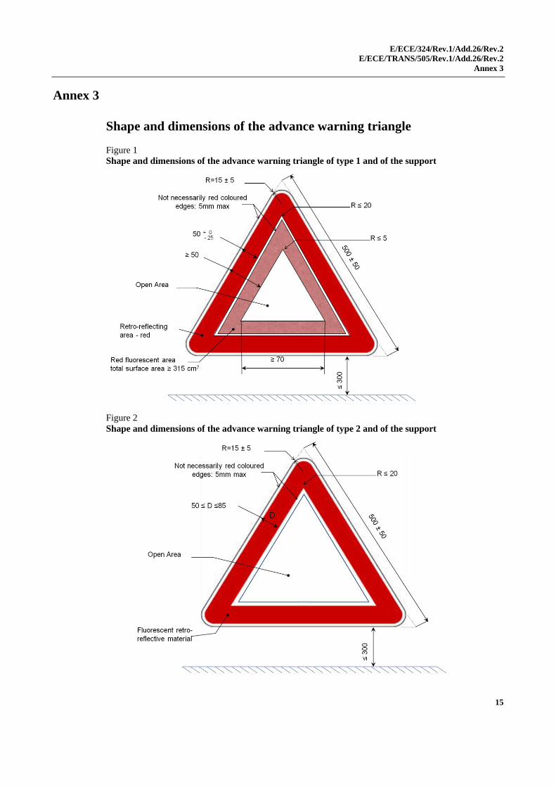
7.1.1.1. The theoretical sides of the triangle shall be 500 ± 50 mm long.
7.1.1.2. In the case of an advance warning triangle of type 1, the retro-reflecting units
shall be arranged along the edge within a strip of an unvarying width which
shall be between 25 mm and 50 mm. In the case of an advance warning
triangle of type 2 with fluorescent retro-reflecting material, the unvarying
width shall be between 50 mm and 85 mm.
7.1.1.3 Between the outer edge of the triangle and the retro-reflecting strip there may
be an edging not more than 5 mm wide and not necessarily red-coloured.
7.1.1.4. The retro-reflecting strip may be continuous or not. In the latter case the free
area of the supporting material shall be red (see also paragraph 7.3.1.2. of this
Regulation.
7.1.1.5. In the case of an advance warning triangle of type 1, the fluorescent surface
shall be continuous to the retro-reflecting units. It shall be arranged
symmetrically along the three sides of the triangle. When in use, its surface
area shall be not less than 315 cm2. However, an edging, continuous or not,
not more than 5 mm wide, which need not necessarily be red-coloured, may
be placed between the retro-reflecting surface and the fluorescent surface.
Page 8
E/ECE/324/Rev.1/Add.26/Rev.2
E/ECE/TRANS/505/Rev.1/Add.26/Rev.2
8
7.1.1.6. The side of the open centre of the triangle shall have a minimum length of
70 mm (Fig. 1).
7.1.2. Shape and dimensions of the support
7.1.2.1. The distance between the supporting surface and the lower side of the
advance warning triangle shall not exceed 300 mm.
7.1.3. The fluorescent retro-reflecting material shall be coloured in the mass, either
in the retro-reflective elements or as solid surface layer.
7.2. Colorimetric specification
7.2.1. Retro-reflecting devices
7.2.1.1. Retro-reflecting devices shall be made of material coloured red in the mass.
7.2.1.2. The testing of the colour for retro-reflecting device (night-time colour) shall
be carried out according to the method described in Annex 5, paragraph 2.1.
and the trichromatic co-ordinates of the red reflected luminous flux shall be
within the following limits:
Point 1 2 3 4
x 0.712 0.735 0.589 0.625
y 0.258 0.265 0.376 0.375
7.2.2. Fluorescent materials
7.2.2.1. The fluorescent materials shall either be coloured in the mass or take the form
of separate coatings applied to the surface of the triangle.
7.2.2.2. The testing of the colour of the fluorescent materials (daytime colour) of
advance warning triangle of type 1 or type 2 shall be carried out according to
the method described in Annex 5, paragraph 2.2. and the colour of the
material in new condition shall be within an area of which the corner points
are determined by the following coordinates:
Point 1 2 3 4
x 0.570 0.506 0.595 0.690
y 0.430 0.404 0.315 0.310
7.2.2.3. The testing of the luminance factor of the fluorescent materials shall be
carried out according to the method described in Annex 5, paragraph 3.
The luminance factor including the luminance by reflection and fluorescence
shall be:
(a) For advance warning triangle of type 1, not less than 30 per cent; and
(b) For advance warning triangle of type 2, not less than 25 per cent.
7.2.3. The largest measured trichromatic coordinate y value according to
paragraph 7.2.1.2. (night time colour) shall be smaller or equal to the largest
measured trichromatic coordinate y value according to paragraph 7.2.2.2.
(day time colour).
Page 9
E/ECE/324/Rev.1/Add.26/Rev.2
E/ECE/TRANS/505/Rev.1/Add.26/Rev.2
9
7.3. Photometric specifications
7.3.1. Retro-reflecting devices and fluorescent retro-reflecting material.
7.3.1.1. The values of the CIL of retro-reflecting optical units or the fluorescent retro-
reflecting material shall be not less than those given in the table below,
expressed in millicandelas per lux, for the angles of divergence and the
illumination angle shown:
Illumination angles β
Vertical V (β1) 0° ±20° 0° 0°
Horizontal H (β2) 0° or ±5° 0° ±30° ±40°
Angles of divergence 20' 8,000 4,000 1,700 600
Angles of divergence
1°30' 600 200 100 50
7.3.1.2. The CIL measured on random slices of 50 mm length of the retro-reflecting
device shall lie between extremes having a ratio not in excess of 3. These
slices are taken between the perpendiculars to the side of the triangle and
passing through the corresponding apexes of the central aperture. This
requirement applies to an angle of divergence of 20' and to illumination
angles of V = 0°, H = 0° or ±5° and V = ±20°, H = 0°.
7.3.1.3. Diversity of luminance at angles of illumination of V = 0°, H = ±30°, and
V = 0°, H = ±40° shall be tolerated on condition that the triangular shape
remains clearly discernible, for an angle of divergence of 20' and an
illumination of approximately 1 lux.
7.3.1.4. The measurements referred to above shall be performed by the method
described in Annex 5 to this Regulation, paragraph 4.
8. Test procedure
Every advance warning triangle and its protective cover, if any, shall meet
the requirements of the checks and tests described in Annex 5 to this
Regulation.
9. Modifications of the advance warning triangle type and extension of approval
9.1. Every modification of the triangle type shall be notified to the Type Approval
Authority which granted approval. The Type Approval Authority may then
either:
9.1.1. Consider that the modifications made are unlikely to have an appreciable
adverse effect, and that in any case the triangle still meets the requirements;
or
9.1.2. Require a further report from the technical service responsible for conducting
the tests.
Page 10
E/ECE/324/Rev.1/Add.26/Rev.2
E/ECE/TRANS/505/Rev.1/Add.26/Rev.2
10
9.2. Notice of confirmation of approval, specifying the modifications, or of
refusal of approval shall be communicated by the procedure specified in
paragraph 5.3. above to the Parties to the Agreement which apply this
Regulation.
9.3. The Type Approval Authority issuing the extension of approval shall assign a
series number to each communication form drawn up for such an extension
and inform thereof the other Parties to the 1958 Agreement applying this
Regulation by means of a communication form conforming to the model in
Annex 1 to this Regulation.
10. Conformity of production
The conformity of production procedures shall comply with those set out in
the Agreement, Appendix 2 (E/ECE/324-E/ECE/TRANS/505/Rev.2), with
the following requirements:
10.1. Advance warning triangles approved under this Regulation shall be so
manufactured as to conform to the type approved under this Regulation.
The compliance with the requirements set forth in paragraphs 6., 7. and 8.
above shall be verified as follows:
10.1.1. In addition, the stability in time of the optical properties and colour of retro-
reflecting optical units of advance warning triangles conforming to an
approved type and in use shall be verified. In the event of a systematic
deficiency of the retro-reflecting optical units of advance warning triangles in
use and conforming to an approved type, approval may be withdrawn. A
"systematic deficiency" shall be deemed to exist where an approved type of
advance warning triangle fails to meet the requirements of paragraph 6.2. of
this Regulation.
10.1.2. The minimum requirements for conformity of production control procedures
set forth in Annex 7 to this Regulation shall be complied with.
10.1.3. The minimum requirements for sampling by an inspector set forth in Annex 8
to this Regulation shall be complied with.
10.2. The Type Approval Authority which has granted type approval may at any
time verify the conformity control methods applied in each production
facility. The normal frequency of these verifications shall be once every two
years.
11. Penalties for non-conformity of production
11.1. The approval granted in respect of a type of advance warning triangle may be
withdrawn if the foregoing requirements are not complied with.
11.2. If a Contracting Party to the Agreement applying this Regulation withdraws
an approval it has previously granted, it shall forthwith notify the other
Contracting Parties applying this Regulation thereof by means of a
communication form conforming to the model in Annex 1 to this Regulation.
Page 11
E/ECE/324/Rev.1/Add.26/Rev.2
E/ECE/TRANS/505/Rev.1/Add.26/Rev.2
11
12. Production definitively discontinued
If the holder of the approval completely ceases to manufacture a device under
this Regulation, he shall inform thereof the Type Approval Authority which
granted the approval. Upon receiving the relevant communication that
Authority shall inform the other Parties to the Agreement which apply this
Regulation thereof by means of a communication form conforming to the
model in Annex 1 to this Regulation.
13. Names and addresses of Technical Services conducting approval tests and of Type Approval Authorities
The Contracting Parties to the Agreement applying this Regulation shall
communicate to the secretariat of the United Nations the names and addresses
of the Technical Services conducting approval tests and of the Type Approval
Authorities which grant approval and to which the forms certifying approval
or refusal or withdrawal of approval, issued in other countries, are to be sent.
14. Transitional provisions
14.1. From the date of entry into force of the 04 series of amendments, no
Contracting Party applying this Regulation shall refuse to grant approvals
under this Regulation as amended by the 03 series of amendments.
14.2. As from 36 months after the date of entry into force of the 04 series of
amendments, Contracting Parties applying this Regulation shall grant
approvals only if the advance-warning triangle meets the requirements of this
Regulation as amended by the 04 series of amendments.
14.3. Existing approvals for advance warning triangles already granted under this
Regulation before the date of entry into force of the 04 series of amendments
shall remain valid indefinitely.
14.4. Contracting Parties applying this Regulation shall not refuse to grant
extensions of approvals to the preceding series to this Regulation.
Page 12
E/ECE/324/Rev.1/Add.26/Rev.2
E/ECE/TRANS/505/Rev.1/Add.26/Rev.2
Annex 1
12
Annex 1
Communication
(Maximum format: A4 (210 x 297 mm))
1
Concerning:2 Approval granted
Approval extended
Approval refused
Approval withdrawn
Production definitively discontinued
of a type of advance warning triangle pursuant to Regulation No. 27.
Approval No.: …………................... Extension No.: ...............................................
1. Trade name or mark of the advance warning triangle........................................
2. Manufacturer's name ..........................................................................................
3. Address ..............................................................................................................
4. If applicable, name of manufacturer's representative .........................................
5. Address ..............................................................................................................
6. Brief description of the advance warning triangle .............................................
...........................................................................................................................
7. Submitted for approval on .................................................................................
8. Technical Service conducting approval tests .....................................................
9. Date of report issued by that Service .................................................................
10. Number of report issued by that Service ............................................................
11. Approval granted/extended/refused/withdrawn2
12. Remarks ............................................................................................................
13. Place ..................................................................................................................
14. Date....................................................................................................................
15. Signature ............................................................................................................
1 Distinguishing number of the country which has granted/extended/refused/withdrawn approval (see
approval provisions in the Regulation).
2 Strike out what does not apply.
issued by: Name of administration:
......................................
......................................
......................................
1
1 1
Page 13
E/ECE/324/Rev.1/Add.26/Rev.2
E/ECE/TRANS/505/Rev.1/Add.26/Rev.2
Annex 1
13
16. The following documents, bearing the approval number shown above, are
annexed to this communication:
..... dimensioned drawings
..... photographs
Page 14
E/ECE/324/Rev.1/Add.26/Rev.2
E/ECE/TRANS/505/Rev.1/Add.26/Rev.2
Annex 2
14
Annex 2
Arrangements of the approval mark
a 8 mm
An advance warning triangle bearing one of the approval marks shown above has
been approved in the Netherlands (E 4) under approval number 04216. The first two digits
of the approval number indicate that the approval was granted according to the
requirements of this Regulation as amended by the 04 series of amendments.
Note: The drawings show several possible embodiments and are given by way of example.
The Type Approval Authorities shall avoid using Roman numerals for the approval, in
order to prevent any confusion with other symbols.
27R04216
27R04216
Page 15
E/ECE/324/Rev.1/Add.26/Rev.2
E/ECE/TRANS/505/Rev.1/Add.26/Rev.2
Annex 3
15
Annex 3
Shape and dimensions of the advance warning triangle
Figure 1
Shape and dimensions of the advance warning triangle of type 1 and of the support
Figure 2
Shape and dimensions of the advance warning triangle of type 2 and of the support
Page 16
E/ECE/324/Rev.1/Add.26/Rev.2
E/ECE/TRANS/505/Rev.1/Add.26/Rev.2
Annex 3
16
Figure 3
Test device for clearance to ground
Dimensions in mm
Square hole
Page 17
E/ECE/324/Rev.1/Add.26/Rev.2
E/ECE/TRANS/505/Rev.1/Add.26/Rev.2
Annex 4
17
Annex 4
Determination of the roughness of the road surface "sandy beach" method
1. Purpose of the method
1.1. The purpose of this method is to describe and to determine to a certain extent
the geometric roughness of that part of the road surface on which the advance
warning triangle is placed during the test of stability in wind, as required
according to Annex 5, paragraph 10.
2. Principle of the method
2.1. A known volume V of sand is spread evenly on the surface of the
carriageway in the form of a circle. The ratio of the volume used to the area S
covered is defined as "mean sand depth" HS and is expressed in mm:
S
VHS
2.2. The test is carried out by means of round-grain, dry sand and having a grain
size between 0.160 mm and 0.315 mm. The volume amounts to
25 ml ± 0.15 ml. The sand is spread out over the surface where the test is
carried out by means of a flat, circular disc with a diameter of 65 mm, one
side of which is covered with a sheet of rubber having a thickness of 1.5 mm
to 2.5 mm and the other being provided with an appropriate handle. If the
diameter of the circular area covered with sand is D mm, the mean sand depth
will be calculated in accordance with the formula:
mm10D
254HS 3
2
3. Performance of the test
3.1. The surface on which the test is to be carried out shall be dry and at first be
brushed with a soft brush to remove any dirt or loose gravel.
3.2. The sand which has been firmly filled into an appropriate receptacle is then
poured out on the surface to be tested in a single heap. The sand is then
carefully spread out on the surface by means of repeated circular movements
of the rubber faced disc so as to form the largest possible round area covered
with sand. The sand will then fill all depressions and hollows.
3.3. Two diameters, at right angles to one another, of the "beach" thus formed are
usually measured. The mean value is rounded off to the nearest 5 mm, with
the depth of the sand HS being calculated according to the formula given in
paragraph 2.2. above.
3.4. Six tests of this kind are carried out on the supporting surface, with the parts
to be tested being distributed over the surface to be tested as evenly as
possible. The overall mean of the results obtained is given as the mean sand
depth HS of the road surface where the advance warning triangle has been
placed.
Page 18
E/ECE/324/Rev.1/Add.26/Rev.2
E/ECE/TRANS/505/Rev.1/Add.26/Rev.2
Annex 5
18
Annex 5
Test procedures
1. General
1.1. The applicant shall submit samples, as mentioned in paragraphs 3.4. and 3.5.
of this Regulation, for approval.
1.2. After verification of the general specifications (paragraph 6. of the
Regulation) and the specifications of shape and dimensions (paragraph 7.1. of
this Regulation), all samples shall be subjected to the heat resistance test
(paragraph 7. below) and examined after at least one hour of rest.
1.3. The CIL value of the four samples of the advance warning triangles
submitted is measured at an observation angle of 20' and at an illumination
angle with the components V = 0°, H = ±5°; this test is carried out in
accordance with the method described in paragraph 4. below.
1.4. The two samples with the smallest and the largest CIL value in the tests
according to paragraph 1.3. above shall be subsequently subjected to the
following tests:
1.4.1. Measurement of the values of the CIL in respect of the observation and
illumination angles referred to in paragraphs 7.3.1.1. and 7.3.1.2. of this
Regulation according to the method described in paragraph 4. below.
1.4.2. Testing of the colour of the retro-reflected light according to paragraph 2.1.
below on the sample with the highest CIL concerned shall be examined.
1.4.3. Test of clearance to ground according to paragraph 5. below.
1.4.4. Mechanical solidity test according to paragraph 6. below.
1.5. One sample other than those referred to in paragraph 1.4. above shall be
subjected to the following tests:
1.5.1. Testing of resistance to penetration of water into the retro-reflecting device
according to paragraph 11.1. below or if relevant, of the mirror-backed
reverse side of the retro-reflecting device, according to paragraph 11.2.
below.
1.6. The second sample, other than those referred to in paragraph 1.4. above, shall
be subjected to the following tests:
1.6.1. Water test according to paragraph 8. below.
1.6.2. Testing of resistance to fuels according to paragraph 9. below.
1.6.3. Test of stability against wind according to paragraph 10. below.
1.7. After the tests specified in paragraph 1.4. above, the two samples submitted
according to paragraph 3.5. of this Regulation shall be subjected to the
following tests:
1.7.1. Colour test according to paragraph 2.2. below;
1.7.2. Test of the luminance factor according to paragraph 3. below;
Page 19
E/ECE/324/Rev.1/Add.26/Rev.2
E/ECE/TRANS/505/Rev.1/Add.26/Rev.2
Annex 5
19
1.7.3. Test of weather resistance according to paragraph 12. below.
2. Colour tests
2.1. Colour of retro-reflecting devices
2.1.1. The colour of the retro- reflecting devices to be tested when illuminated by
the CIE standard illuminant A with an angle of divergence of 1/3° and an
illumination angle V = H = 0°, or, if this produces a colourless surface
reflection, an angle V = ±5°, H = 0° shall be applied.
2.2. Colour of the fluorescent material
2.2.1. Colour of the fluorescent material for the advance warning triangle of type 1
For testing the colour of the fluorescent material, the material shall be
illuminated by the CIE Standard Illuminant D65 (ISO 11664-2:2007(E)/CIE
S 014-2/E:2006) and measured with a spectrophotometer in accordance with
the provisions of Publication CIE 15:2004, Recommendations on
Colorimetry - Second Edition, either illuminated polychromatically or with a
monochromator providing stepwise the CIE Standard Illuminant D 65 (ISO
11664-2:2007(E)/CIE S 014-2/E:2006) at an angle 45º to the normal and
viewed along the normal (geometry 45/0). In the latter case, the stepwise
resolution λ shall be not larger than 10 nm. Alternatively similar
"illuminants" are allowed, if verified that the colorimetric measuring
procedure is of the same sufficient accuracy, meaning that the quality of the
simulation of D65 shall be assessed by the method described in ISO
23603:2005(E)/CIE S 012/E:2004. The spectral distribution of the illuminant
shall be in category BC (CIELAB) or better.
The illumination shall be carried out at an angle 45º to the normal and viewed
along the normal (geometry 45/0).
2.2.2. Colour of the fluorescent material for the advance warning triangle of type 2
For testing the colour of the fluorescent material, the material shall be
illuminated by the CIE Standard Illuminant D65 (ISO 11664-2:2007(E)/CIE
S 014-2/E:2006) and measured with a spectrophotometer in accordance with
the provisions of publication CIE 15:2004, Recommendations on
Colorimetry - second edition, either illuminated polychromatically or with a
monochromator providing stepwise the CIE Standard Illuminant D 65 (ISO
11664-2:2007(E)/CIE S 014-2/E:2006). In the latter case, the stepwise
resolution λ shall be not larger than 10 nm. Alternatively similar
"illuminants" are allowed, if verified that the colorimetric measuring
procedure is of the same sufficient accuracy, meaning that the quality of the
simulation of D65 shall be assessed by the method described in ISO
23603:2005(E)/CIE S 012/E:2004. The spectral distribution of the illuminant
shall be in category BC (CIELAB) or better. The illumination shall be carried
out circumferential at an angle 45º to the normal and viewed along the
normal (annular geometry 45/0) (circumferential/normal geometry), as
described in Annex 10 to this Regulation.
3. Determination of the luminance factor of the fluorescent material
3.1. For the determination of the luminance factor the sample shall be tested for
advance warning triangle of
Page 20
E/ECE/324/Rev.1/Add.26/Rev.2
E/ECE/TRANS/505/Rev.1/Add.26/Rev.2
Annex 5
20
(a) Type 1 with the same method as described in paragraph 2.2.1 of this
annex and
(b) Type 2 with the same method as described in paragraph 2.2.2. of this
annex.
3.1.1 By putting the luminance L of the sample into relation to the luminance Lo of
a perfect diffuser whose luminance factor o is known under identical
conditions of illumination and observation; the luminance factor of the
sample then results from the formula:
o
oL
L
3.1.2. When the colour of the fluorescent material has been colorimetrically
determined in compliance with paragraph 2.2. above, from the ratio of the
tristimulus value Y the sample and the tristimulus value of the perfect
diffuser Yo; in this case it is:
0Y
Y
4. Measurement of the value of the CIL of retro-reflecting devices
4.1. For this measurement it is assumed that the direction of illumination
H = V = for the advance warning triangle in its position of use is parallel to
the base plane and vertical to the lower side of the triangle, which in turn is
parallel to the said base plane.
4.2. The measurement shall be performed by the method described in Annex 6 to
this Regulation.
5. Test of clearance to ground
5.1. The advance warning triangle shall be required to pass the following tests:
5.1.1. For this test, the apparatus shown in Annex 3, Figure 2, to this Regulation,
which has the form of an inverted hollow pyramid, shall be placed on a
horizontal base plane.
5.1.2. The individual supports to the ground shall be placed one after another in the
square hole of the test apparatus. During the test of each support, it shall be
required to find a position of the test apparatus in relation to the advance
warning triangle and its supporting device, which is favourable for the
triangle and which ensures that:
5.1.2.1. All supports are resting simultaneously on the base plane,
5.1.2.2. Outside the area covered by the test apparatus, the distance between the base
plane and parts of the triangle as well as of the supporting device is at least
50 mm (with the exception of the supports proper).
6. Mechanical solidity test
6.1. When the advance warning triangle has been set up as required by the
manufacturer and its bases are firmly held, a force of 2 N shall be applied to
the apex of the triangle parallel to the supporting surface and normal to the
lower side of the triangle.
Page 21
E/ECE/324/Rev.1/Add.26/Rev.2
E/ECE/TRANS/505/Rev.1/Add.26/Rev.2
Annex 5
21
6.2. The apex of the triangle shall not move more than 5 cm in the direction in
which the force is exerted.
6.3. After the test, the position of the device shall not be significantly different
from its original position.
7. Test of heat and low-temperature resistance
7.1. The advance warning triangle, in its protective cover, if provided, shall be
kept for 12 consecutive hours in a dry atmosphere at a temperature of
60 °C ± 2 °C.
7.2. After the test, no cracking or noticeable distortion of the device shall be
visible; this applies in particular to the retro-reflecting device. The cover shall
be readily openable and shall not adhere to the triangle.
7.3. After the heat-resistance test and subsequent storage for 12 consecutive hours
at a temperature of 25 °C ± 5 °C, the advance warning triangle, in its
protective cover, is to be kept for another 12 hours in a dry atmosphere at a
temperature of -40 °C ± 2 °C.
7.4. Immediately after removal from the cold room, no fractures or any visible
distortion shall be noticeable on the device and especially on its optical parts.
The protective cover, if provided, shall be properly openable, and it shall
neither tear nor adhere to the advance warning triangle.
8. Water test
The triangle - collapsible advance warning triangles are to be assembled as
for use - shall be immersed flat for two hours on the bottom of a tank
containing water at 25 °C ± 5 °C, with the active face of the triangle showing
upwards and being 5 cm under the surface of the water. The triangle shall
then be removed and dried. No part of the device may exhibit clear signs of
deterioration which might impair the effectiveness of the triangle.
9. Test of resistance to fuels
The triangle and its protective cover shall be immersed separately in a tank
containing a mixture of 70 per cent n-heptane and 30 per cent toluene. After
60 seconds they shall be removed from the tank and drained of excess liquid.
The triangle shall then be placed in its cover and the unit shall be laid flat in a
still atmosphere. When completely dried, the triangle shall not adhere to its
protective cover, and there shall be no visually noticeable change on its
surface and shall not present apparent detrimental modifications; however,
slight surface cracks may be tolerated.
10. Test of stability against wind
10.1. The advance warning triangle shall be set up in a wind tunnel, on a base
measuring about 1.50 m by 1.20 m with a surface formed of abrasive
material of the type P36 corresponding to the FEPA1
specification 43-1-2006. This surface shall be characterised by its geometric
roughness, HS = 0.5 mm ± 0.05 mm, which shall be defined and determined
by the so-called "sandy beach" method according to Annex 4 of this
Regulation.
1 FEPA: Federation of European Producers of Abrasives, 20 Avenue Reille, 75014 Paris, France.
Page 22
E/ECE/324/Rev.1/Add.26/Rev.2
E/ECE/TRANS/505/Rev.1/Add.26/Rev.2
Annex 5
22
To avoid a laminar boundary layer of the incident flow over the surface of the
base, this base shall have a splitter plate and shall be set up in such a way,
that the flow is completely around the plate.
10.2. For the air flow the following conditions shall apply:
(a) The air stream shall reach a dynamic pressure of 180 Pa; and shall
have a flow field which shall be homogeneous and free of turbulence;
(b) The dimension of the flow field shall be such, that horizontally to each
corner and vertical to the top of the advance warning triangle a
clearance of at least 150 mm to the border line of this flow field shall
exist;
(c) The air stream (flow field) shall be parallel to the supporting surface,
in a direction which seems to be most unfavourable for the stability;
(d) In the case of a closed wind tunnel, the area of the advance warning
triangle shall be not larger than 5 per cent of the area cross-section of
the closed wind tunnel.
10.3. When set up in this manner, the advance warning triangle shall be subjected
for 3 minutes to this open air stream.
10.4. The advance warning triangle shall neither overturn nor shift. Slight shifting
of the points of contact with the road surface by not more than 5 cm,
however, shall be allowed.
10.5. The retro-reflecting triangular part of the device shall not rotate through more
than 10° round a horizontal axis or a vertical axis from its initial position.
The rotation around the horizontal axis or the vertical axis shall be
determined by the aid of a virtual plane at the initial position of the retro-
reflecting triangular part of the device, which is orthogonal to the base and
orthogonal to the air stream.
11. Test of resistance of the retro-reflecting device or fluorescent retro-reflecting
material
11.1. Test of resistance to penetration of water
11.1.1. The triangle - collapsible triangles are to be assembled as for use - shall be
immersed for 10 minutes in water having a temperature of 50 °C ± 5 °C, with
the highest point of the upper part of the illuminating surface being about
20 mm below the water surface. Immediately afterwards, this retro-reflecting
device shall be immersed under the same conditions in water having a
temperature of 25 °C ± 5 °C.
11.1.2. After this test, no water shall have penetrated to the reflecting surface of the
retro-reflecting device. If a visual inspection clearly reveals the presence of
water, the device has not passed the test. Water or water vapour penetration
into the edges of fluorescent retro-reflecting materials shall not be deemed to
indicate failure.
11.1.3. If the visual inspection does not reveal the presence of water, or in case of
doubt the value of the CIL shall again be measured under the same conditions
as specified in paragraph 1.2. above, after the retro-reflecting device has been
gently shaken to remove excess water from the outside. The CIL shall not
have diminished by more than 40 per cent of the values recorded before the
test.
Page 23
E/ECE/324/Rev.1/Add.26/Rev.2
E/ECE/TRANS/505/Rev.1/Add.26/Rev.2
Annex 5
23
11.2. Test of resistance of the accessible reverse side of the mirror-backed retro-
reflecting device
The reverse side of the retro-reflecting device shall be brushed with a hard
nylon brush and then covered or thoroughly wetted for one minute with a
mixture of 70 per cent n-heptane and 30 per cent toluene. The fuel shall then
be removed and the device allowed to dry. As soon as evaporation is
completed, the reverse side shall be brushed with the same brush as before.
The value of the CIL shall then be measured under the same conditions as
specified in paragraph 1.2. above, after the whole surface of the mirror-
coated reverse side has been covered with Indian ink. The CIL shall not have
diminished by more than 40 per cent of the values recorded before the test.
This test is not applicable for fluorescent retro-reflecting material.
12. Test of the weather-resistance of the luminance factor and of the colour of the
fluorescent (advance warning triangle of type 1) and fluorescent retro-
reflecting (advance warning triangle of type 2) materials.
12.1. One of the samples of the fluorescent material submitted according to
paragraph 3.5. of this Regulation shall be subjected to a temperature and
irradiation test described in Annex 9 to this Regulation until the contrast
No. 4 of the grey scale has been reached for the reference sample No. 5 or the
light exposure equivalents for blue wool light fastness references sample
No. 5 to fade to the grey scale 4 for exposure by a Xenon-arc lamp has been
reached.
12.2. After this test, the colour co-ordinates of the fluorescent material shall
comply with colour specification in paragraph 7.2.2.2. of this Regulation.
The luminance factor (see paragraph 3. above) shall comply with paragraph
7.2.2.3. of this Regulation and shall not have increased by more than 5 per
cent compared with the value ascertained according to paragraph 1.7.2. above
12.3. The sample shall not exhibit any visible damage such as cracks, scaling or
peeling of the fluorescent or of the fluorescent retro-reflecting material.
12.4. If the fluorescent material is an adhesive film which had already successfully
passed the above-mentioned tests in a previous approval test, the test need
not be repeated; a corresponding note shall be entered under item 12
("Remarks") in the communication concerning approval (Annex 1 to this
Regulation).
Page 24
E/ECE/324/Rev.1/Add.26/Rev.2
E/ECE/TRANS/505/Rev.1/Add.26/Rev.2
Annex 6
24
Annex 6
Method for measurement of the CIL of retro-reflecting devices and fluorescent retro-reflecting materials
1. Definitions
Needed definitions are explained by Figures 1 to 4.
2. Dimensional and physical specifications for the photometry of retro-
reflectors
2.1. The CIE-angular system as shown in Figure 1 shall be used.
An adequate support (goniometer) is demonstrated in Figure 2.
2.2. The measuring distance shall be chosen in such an order that at least the
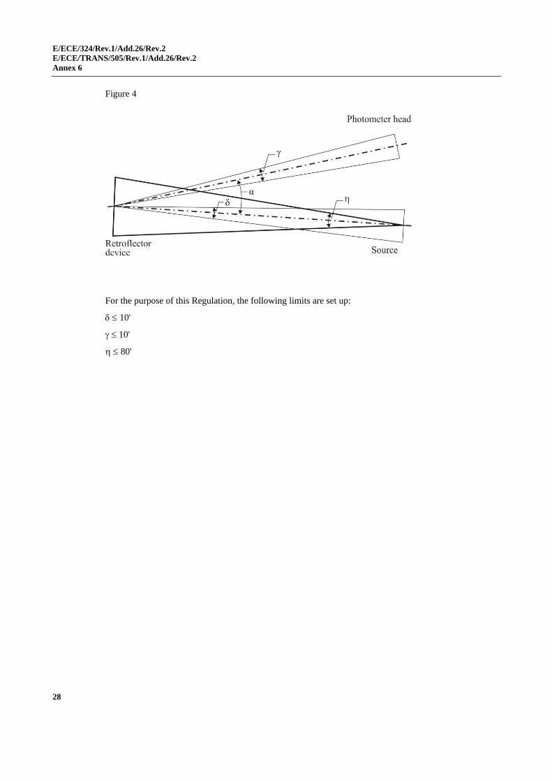
limits for the angles , and given in Figure 4 are respected, but not lower
than 10 m or its optical equivalent.
2.3. The illuminance at the retro-reflector
The illuminance over the useful area of the retro-reflector, measured
perpendicular to the incident light shall be sufficiently uniform. A check on
this condition requires a measuring element, the sensitive area of which is not
greater than one-tenth of the area to be examined. The variation in the value
of the illuminance shall then comply with the condition:
05.1valueimummin
valueimummax
2.4. The colour temperature and the spectral distribution of the source
The source used for illuminating the retro-reflector shall as faithfully as
possible represent the CIE illuminant A, both as regards colour temperature
and spectral power distribution.
2.5. The photometer head (measuring element)
2.5.1. The photometer head shall be corrected to the spectral luminous efficiency
for the CIE standard photometric observer in photopic vision.
2.5.2. The device shall not show a perceptible change in local sensitivity within the
area of its aperture; otherwise suitable provisions shall be added, e.g. the
application of a diffusing window at a certain distance in front of the
sensitive surface.
2.5.3. Experience has shown that non-linearity of photometer heads may be a
problem with the very small light quantities which are the rule in the
photometry of retro-reflectors. A check at comparable illuminance levels on
the photometer head is recommended.
2.6. The influence of a regular reflection
The amount and distribution of the regular reflection from the surface of the
retro-reflector depends on the flatness and the gloss of the surface. In general,
regular reflection is best avoided when the reference axis is placed so that the
regular reflection is directed on the opposite side of the source from the
photometer head (for example with 1 = -5°).
Page 25
E/ECE/324/Rev.1/Add.26/Rev.2
E/ECE/TRANS/505/Rev.1/Add.26/Rev.2
Annex 6
25
3. Measurement precautions in the photometry of retro-reflection
3.1. Residual and stray light
3.1.1. Since very low light levels are to be measured special precautions are needed
to minimize errors due to stray light. The background to the sample and the
framework of the sample holder should be matt black and the field of view of
the photometer head and the spread of light from both the sample and the
source should each be restricted as much as possible.
3.1.2. Reflections from the floor and walls which occur over the relatively long test
distances used shall be screened from both the sample and the photometer
head by baffles. The importance of looking from the photometer head to
check for sources of stray light cannot be over emphasized.
3.1.3. A valuable aid to reducing the amount of stray light in the laboratory is to use
a slide projector type of optical system for the light source. With this, an iris
diaphragm or suitable sized apertures may be used in the optical system to
restrict the illuminated area at the sample to the minimum size needed to
provide uniform illuminance over the sample.
3.1.4. Residual stray light should always be allowed for by measuring it when the
sample is covered by an opaque matt black surface, zigzag folded black paper
of the same size and shape or a specular black surface suitably oriented with
a light trap. This value should be subtracted from that measured on the retro-
reflector.
3.2. Stability of the apparatus
3.2.1. The light source and photometer head should remain stable throughout the
period of the test. Since the sensitivity and the adaptation to the V ()
function of most photometer heads change with temperature, the laboratory
ambient temperature should not vary significantly during this period.
Sufficient time should always be allowed for the apparatus to stabilize before
commencing measurements.
3.2.2. The power supply to the light source should be adequately stabilized so that
the luminous intensity of the lamp can be maintained throughout the test to
within the required accuracy for the work.
3.2.3. A useful check on the overall stability of the reflex photometer during a
series of tests is to make periodic measurements of CIL values of a stable
reference standard.
3.2.4. Another technique is to incorporate in the apparatus an auxiliary detector to
check or monitor the output of the light source. Although the output from the
auxiliary detector can be checked for any change in reading, a useful
refinement is to use the output to alter electronically the sensitivity of the
main reflex photometer head and compensate automatically for changes in
the light output of the source.
Page 26
E/ECE/324/Rev.1/Add.26/Rev.2
E/ECE/TRANS/505/Rev.1/Add.26/Rev.2
Annex 6
26
Figure 1
The CIE co-ordinate system
1: First axis I: Illumination Axis : Observation angle
2: Second axis O: Observation axis ß1, ß2: Entrance angles
R: Reference axis ɛ: Rotation angle
The CIE angular system for specifying and measuring retro-reflectors.
The first axis is perpendicular to the plane containing the observation axis
and the illumination axis. The second axis is perpendicular both to the first
axis and to the reference axis. All axes, angles, and directions of rotation are
shown positive.
Notes: (a) The principle fixed axis is the illumination axis.
(b) The first axis is fixed perpendicular to the plane containing the
observation and illumination axis.
(c) The reference axis is fixed in the retro-reflector and moveable
with ß1 and ß2.
Page 27
E/ECE/324/Rev.1/Add.26/Rev.2
E/ECE/TRANS/505/Rev.1/Add.26/Rev.2
Annex 6
27
Figure 2
Goniometer mechanism embodying the CIE angular system
1: First axis I: Illumination Axis α: Observation angle
2: Second axis O: Observation axis ß1, ß2: Entrance angles
R: Reference axis ɛ: Rotation angle
P: Retro-reflective material
Representation of a goniometer mechanism embodying the CIE
angular system for specifying and measuring retro-reflectors. All angles and
directions of rotation are shown positive.
Figure 3
Page 28
E/ECE/324/Rev.1/Add.26/Rev.2
E/ECE/TRANS/505/Rev.1/Add.26/Rev.2
Annex 6
28
Figure 4
For the purpose of this Regulation, the following limits are set up:
10'
10'
80'
Page 29
E/ECE/324/Rev.1/Add.26/Rev.2
E/ECE/TRANS/505/Rev.1/Add.26/Rev.2
Annex 7
29
Annex 7
Minimum requirements for conformity of production control procedures
1. General
1.1. The conformity requirements shall be considered satisfied from a mechanical
and geometric standpoint, if the differences do not exceed inevitable
manufacturing deviations within the requirements of this Regulation.
1.2. With respect to photometric performances, the conformity of mass produced
advance warning triangles shall not be contested if, when testing photometric
performances of any advance warning triangle chosen at random no
measured value deviates unfavourably by more than 20 per cent from the
minimum values prescribed in this Regulation.
1.3. The chromaticity coordinates shall be complied with.
2. Minimum requirements for verification of conformity by the manufacturer
For each type of advance warning triangle the holder of the approval mark
shall carry out at least the following tests, at appropriate intervals. The tests
shall be carried out in accordance with the provisions of this Regulation. If
any sampling shows non-conformity with regard to the type of test
concerned, further samples shall be taken and tested. The manufacturer shall
take steps to ensure the conformity of the production concerned.
2.1. Nature of tests
Tests of conformity in this Regulation shall cover the photometric and
colorimetric characteristics, the test of weather resistance of these
characteristics and the resistance to penetration of water.
2.2. Methods used in tests
2.2.1. Tests shall generally be carried out in accordance with the methods set out in
this Regulation.
2.2.2. In any test of conformity carried out by the manufacturer, equivalent methods
may be used with the consent of the competent authority responsible for
approval tests. The manufacturer is responsible for proving that the applied
methods are equivalent to those laid down in this Regulation.
2.2.3. The application of paragraphs 2.2.1. and 2.2.2. above. requires regular
calibration of test apparatus and its correlation with measurements made by a
competent authority.
2.2.4. In all cases the reference methods shall be those of this Regulation,
particularly for the purpose of administrative verification and sampling.
2.3. Nature of sampling
Samples of advance warning triangles shall be selected at random from the
production of a uniform batch. A uniform batch means a set of advance
warning triangles of the same type, defined according to the production
methods of the manufacturer.
Page 30
E/ECE/324/Rev.1/Add.26/Rev.2
E/ECE/TRANS/505/Rev.1/Add.26/Rev.2
Annex 7
30
The assessment shall in general cover series production from individual
factories. However, a manufacturer may group together records concerning
the same type from several factories, provided these operate under the same
quality system and quality management.
2.4. Measured and recorded photometric characteristics
The sampled advance warning triangle shall be subjected to photometric
measurements at the points and the chromaticity coordinates provided for in
the Regulation.
2.5. Criteria governing acceptability
The manufacturer is responsible for carrying out a statistical study of the test
results and for defining, in agreement with the Type Approval Authority,
criteria governing the acceptability of his products in order to meet the
specifications laid down for verification of conformity of products in
paragraph 10.1. of this Regulation.
The criteria governing the acceptability shall be such that, with a confidence
level of 95 per cent, the minimum probability of passing a spot check in
accordance with Annex 8 (first sampling) would be 0.95.
Page 31
E/ECE/324/Rev.1/Add.26/Rev.2
E/ECE/TRANS/505/Rev.1/Add.26/Rev.2
Annex 8
31
Annex 8
Minimum requirements for sampling by an inspector
1. General
1.1. The conformity requirements shall be considered satisfied from a mechanical
and a geometric standpoint, in accordance with the requirements of this
Regulation, if any, if the differences do not exceed inevitable manufacturing
deviations.
1.2. With respect to photometric performance, the conformity of mass produced
advance warning triangles shall not be contested if, when testing photometric
performances of any advance warning triangle chosen at random:
1.2.1. No measured value deviates unfavourably by more than 20 per cent from the
minimum values prescribed in this Regulation.
1.2.2. Advance warning triangles with apparent defects are disregarded.
1.3. The chromaticity coordinates shall be complied with.
2. First sampling
In the first sampling four advance warning triangles are selected at random.
The first sample of two is marked A, the second sample of two is marked B.
2.1. The conformity is not contested
2.1.1. Following the sampling procedure shown in Figure 1 of this annex the
conformity of mass-produced advance warning triangles shall not be
contested if the deviation of the measured values of the advance warning
triangles in the unfavourable directions are:
2.1.1.1. Sample A
A1: one advance warning triangle 0 per cent
one advance warning triangle not more than 20 per cent
A2: both advance warning triangles more than 0 per cent
but not more than 20 per cent
go to sample B
2.1.1.2. Sample B
B1: both advance warning triangles 0 per cent
2.2. The conformity is contested
2.2.1. Following the sampling procedure shown in Figure 1 of this annex the
conformity of mass-produced advance warning triangles shall be contested
and the manufacturer requested to make his production meet the requirements
(alignment) if the deviations of the measured values of the advance warning
triangles are:
Page 32
E/ECE/324/Rev.1/Add.26/Rev.2
E/ECE/TRANS/505/Rev.1/Add.26/Rev.2
Annex 8
32
2.2.1.1. Sample A
A3: one advance warning triangle not more than 20 per cent
one advance warning triangle more than 20 per cent
but not more than 30 per cent
2.2.1.2. Sample B
B2: in the case of A2
one advance warning triangle more than 0 per cent
but not more than 20 per cent
one advance warning triangle not more than 20 per cent
B3: in the case of A2
one advance warning triangle 0 per cent
one advance warning triangle more than 20 per cent
but not more than 30 per cent
2.3. Approval withdrawn
Conformity shall be contested and paragraph 11. of this Regulation applied
if, following the sampling procedure in Figure 1 of this annex, the deviations
of the measured values of the advance warning triangles are:
2.3.1. Sample A
A4: one advance warning triangle not more than 20 per cent
one advance warning triangle more than 30 per cent
A5: both advance warning triangles more than 20 per cent
2.3.2. Sample B
B4: in the case of A2
one advance warning triangle more than 0 per cent
but not more than 20 per cent
one advance warning triangle more than 20 per cent
B5: in the case of A2
both advance warning triangles more than 20 per cent
B6: in the case of A2
one advance warning triangle 0 per cent
one advance warning triangle more than 30 per cent
3. Repeated sampling
In the cases of A3, B2, B3 a repeated sampling, third sample C of two
advance warning triangles and fourth sample D of two advance warning
triangles, selected from stock manufactured after alignment, is necessary
within two months' time after the notification.
Page 33
E/ECE/324/Rev.1/Add.26/Rev.2
E/ECE/TRANS/505/Rev.1/Add.26/Rev.2
Annex 8
33
3.1. The conformity is not contested
3.1.1. Following the sampling procedure shown in Figure 1 of this annex the
conformity of mass-produced advance warning triangles shall not be
contested if the deviations of the measured values of the advance warning
triangles are:
3.1.1.1. Sample C
C1: one advance warning triangle 0 per cent
one advance warning triangle not more than 20 per cent
C2: both advance warning triangles more than 0 per cent
but not more than 20 per cent
go to sample D
3.1.1.2. Sample D
D1: in the case of C2
both advance warning triangles 0 per cent
3.2. The conformity is contested
3.2.1. Following the sampling procedure shown in Figure 1 of this annex the
conformity of mass-produced advance warning triangles shall be contested
and the manufacturer requested to make his production meet the requirements
(alignment) if the deviations of the measured values of the advance warning
triangles are:
3.2.1.1. Sample D
D2: in the case of C2
one advance warning triangle more than 0 per cent
but not more than 20 per cent
one advance warning triangle not more than 20 per cent
3.3. Approval withdrawn
Conformity shall be contested and paragraph 11. of this Regulation applied
if, following the sampling procedure in Figure 1 of this annex, the deviations
of the measured values of the advance warning triangles are:
3.3.1. Sample C
C3: one advance warning triangle not more than 20 per cent
one advance warning triangle more than 20 per cent
C4: both advance warning triangles more than 20 per cent
3.3.2. Sample D
D3: in the case of C2
one advance warning triangle 0 or more than 0 per cent
one advance warning triangle more than 20 per cent
Page 34
E/ECE/324/Rev.1/Add.26/Rev.2
E/ECE/TRANS/505/Rev.1/Add.26/Rev.2
Annex 8
34
4. Additional tests
With respect to the verification of the normal use the following procedures
shall be applied:
One additional advance warning triangle shall be tested according to the
procedures described in paragraphs 1.4.3. to 1.7.3. of annex 5.
The advance warning triangles shall be considered as acceptable if the tests
have been passed.
However, if the test on this sample is not complied with, the two other
additional advance warning triangles shall be subjected to the same procedure
and both shall pass the test.
Page 35
E/ECE/324/Rev.1/Add.26/Rev.2
E/ECE/TRANS/505/Rev.1/Add.26/Rev.2
Annex 8
35
Figure 1
END
END
First Sampling4 devices selected at random split into samples A&B
A B2 devices 2 devices
A1
A2
A3
C3
C4
A4
A5
C1
C2
C D
B1
B2
B3
D1
D2
D3
B4
BB5
B6
0
X
<20
>0<20 <20
>0
0 <20
>0<20 <20
>0
<20>0
0 0
<20
>0<20
0 0
<20
<20
0 >30
>30<20
>0 >20
>20>20
<20>0
>20
>20<300
>20
>20>20
>20 >20
go over to sample B
AlignmentManufacturer is ordered to bring
the products in line with
Repeated Sampling
4 devices selected at random split into samples C&D
<20>20<30
go to alignment
go over to sample D
Approval
withdrawn
Maximum deviation [%] in the unfavourable
direction in relation to the limit values
Po
ssib
le r
esu
lts o
n s
am
ple
A
Po
ssib
le r
esu
lts o
n s
am
ple
C
the requirements
2 devices 2 devices
END
END
Po
ssib
le re
su
lts o
n s
am
ple
B
Po
ssib
le re
su
lts o
n s
am
ple
D
Page 36
E/ECE/324/Rev.1/Add.26/Rev.2
E/ECE/TRANS/505/Rev.1/Add.26/Rev.2
Annex 9
36
Annex 9
Colour fastness to artificial light Xenon-arc lamp test
1. Scope
This annex specifies a method intended for determining the resistance of the
colour of test samples of all kinds and in all forms to the action of an artificial
light source representative of natural daylight (D65).
2. Principle
A specimen of the test samples to be tested is exposed to artificial light under
prescribed conditions, along with a blue wool reference as specified.
3. Reference materials
The colour fastness ratings mentioned in this annex are obtained by
comparison unexposed with exposed specified blue wool references for
verification of the radiation dose as a required maximum contrast in this
Regulation.
3.1. Blue wool references developed and produced in Europe are identified by the
numerical designation 1 to 8. These references are blue wool cloths dyed with
the dyes listed in Table 1. For the test procedure of this Regulation described
by this annex, only the blue wool references 5 and 7 will be applied as
described in Table 1 below.
Table 1
Dyes for blue wool references 5 and 7
Reference Dye (Colour Index designation) 1
5
7
Cl Acid Blue 47
Cl Solubilised Vat Blue 5
1 The Colour Index (third edition) is published by The Society of Dyers and
Colourists, P.O. Box 244, Perkin House, 82 Grattan Road, Bradford BD1 2JB,
UK, and by The American Association of Textile Chemists and Colorists, P.O.
Box 12215, Research Triangle Park, NC 27709-2215, USA.
4. Grey scale
The grey scale for determining changes in colour of test samples in colour
fastness tests. A precise colorimetric specification of the scale is given in
Appendix 1 to this annex.
4.1. The use of the scale is described in paragraph 2. of Appendix 1 to this annex.
5. Xenon-arc lamp apparatus
The apparatus shall be either an air-cooled or water-cooled Xenon-arc
weathering device capable of exposing samples in accordance with EN ISO
4892-2.
5.1. The exposure conditions shall comply with the specifications in the Table 2
below.
Page 37
E/ECE/324/Rev.1/Add.26/Rev.2
E/ECE/TRANS/505/Rev.1/Add.26/Rev.2
Annex 9
37
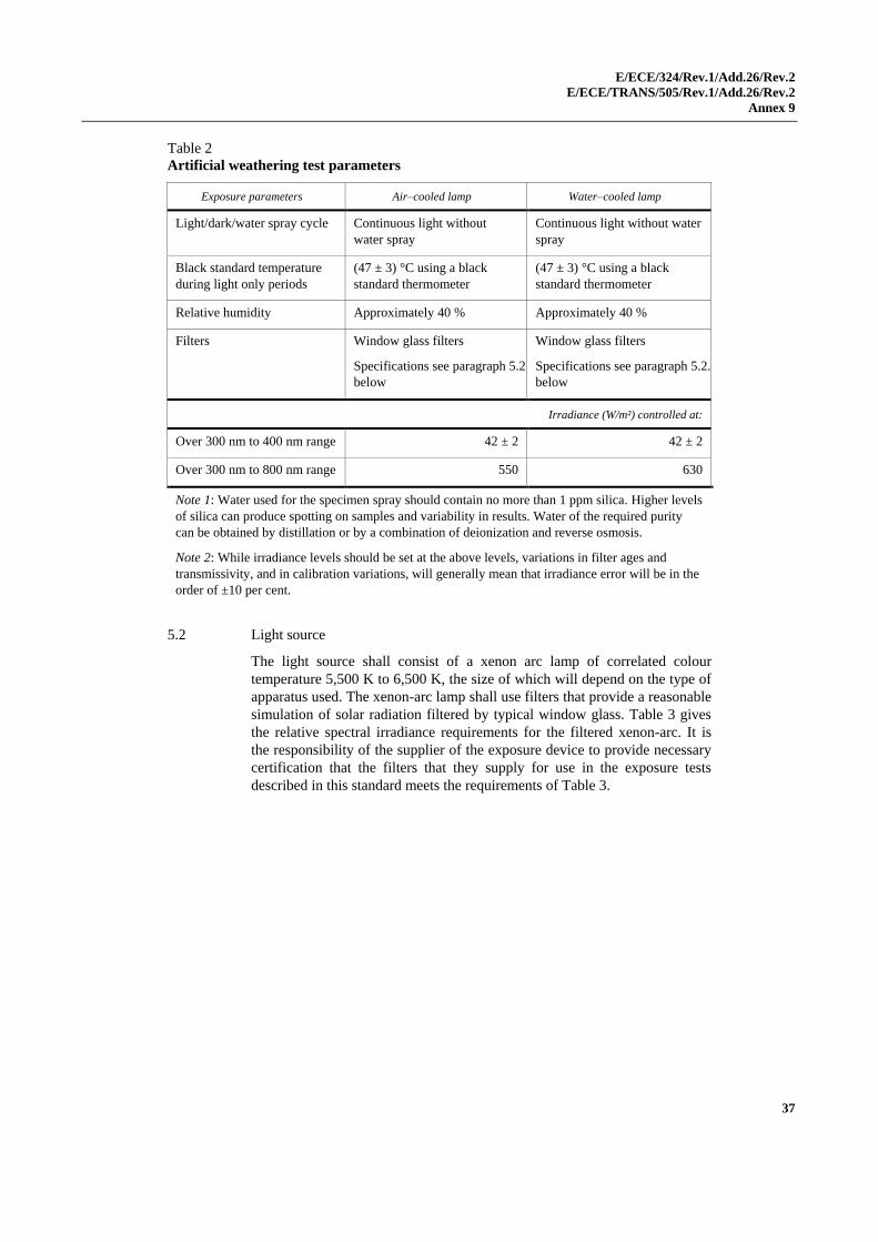
Table 2
Artificial weathering test parameters
5.2 Light source
The light source shall consist of a xenon arc lamp of correlated colour
temperature 5,500 K to 6,500 K, the size of which will depend on the type of
apparatus used. The xenon-arc lamp shall use filters that provide a reasonable
simulation of solar radiation filtered by typical window glass. Table 3 gives
the relative spectral irradiance requirements for the filtered xenon-arc. It is
the responsibility of the supplier of the exposure device to provide necessary
certification that the filters that they supply for use in the exposure tests
described in this standard meets the requirements of Table 3.
Exposure parameters Air–cooled lamp Water–cooled lamp
Light/dark/water spray cycle Continuous light without
water spray
Continuous light without water
spray
Black standard temperature
during light only periods
(47 ± 3) °C using a black
standard thermometer
(47 ± 3) °C using a black
standard thermometer
Relative humidity Approximately 40 % Approximately 40 %
Filters Window glass filters
Specifications see paragraph 5.2.
below
Window glass filters
Specifications see paragraph 5.2.
below
Irradiance (W/m²) controlled at:
Over 300 nm to 400 nm range 42 ± 2 42 ± 2
Over 300 nm to 800 nm range 550 630
Note 1: Water used for the specimen spray should contain no more than 1 ppm silica. Higher levels
of silica can produce spotting on samples and variability in results. Water of the required purity
can be obtained by distillation or by a combination of deionization and reverse osmosis.
Note 2: While irradiance levels should be set at the above levels, variations in filter ages and
transmissivity, and in calibration variations, will generally mean that irradiance error will be in the
order of ±10 per cent.
Page 38
E/ECE/324/Rev.1/Add.26/Rev.2
E/ECE/TRANS/505/Rev.1/Add.26/Rev.2
Annex 9
38
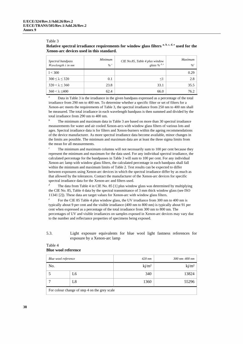
Table 3
Relative spectral irradiance requirements for window glass filters a, b, c, d, e
used for the
Xenon-arc devices used in this standard.
Spectral bandpass
Wavelength λ in nm
Minimum
% c
CIE No.85, Table 4 plus window
glass % d, e
Maximum
%c
l < 300 0.29
300 ≤ λ ≤ 320 0.1 ≤1 2.8
320 < λ ≤ 360 23.8 33.1 35.5
360 < λ ≤400 62.4 66.0 76.2
a Data in Table 3 is the irradiance in the given bandpass expressed as a percentage of the total
irradiance from 290 nm to 400 nm. To determine whether a specific filter or set of filters for a
Xenon-arc meets the requirements of Table 3, the spectral irradiance from 250 nm to 400 nm shall
be measured. The total irradiance in each wavelength bandpass is then summed and divided by the
total irradiance from 290 nm to 400 nm. b The minimum and maximum data in Table 3 are based on more than 30 spectral irradiance
measurements for water and air cooled Xenon-arcs with window glass filters of various lots and
ages. Spectral irradiance data is for filters and Xenon-burners within the ageing recommendations
of the device manufacturer. As more spectral irradiance data become available, minor changes in
the limits are possible. The minimum and maximum data are at least the three sigma limits from
the mean for all measurements. c The minimum and maximum columns will not necessarily sum to 100 per cent because they
represent the minimum and maximum for the data used. For any individual spectral irradiance, the
calculated percentage for the bandpasses in Table 3 will sum to 100 per cent. For any individual
Xenon-arc lamp with window glass filters, the calculated percentage in each bandpass shall fall
within the minimum and maximum limits of Table 2. Test results can be expected to differ
between exposures using Xenon-arc devices in which the spectral irradiance differ by as much as
that allowed by the tolerances. Contact the manufacturer of the Xenon-arc devices for specific
spectral irradiance data for the Xenon-arc and filters used. d The data from Table 4 in CIE No. 85 [1] plus window glass was determined by multiplying
the CIE No. 85, Table 4 data by the spectral transmittance of 3 mm thick window glass (see ISO
11341 [2]). These data are target values for Xenon-arc with window glass filters. e For the CIE 85 Table 4 plus window glass, the UV irradiance from 300 nm to 400 nm is
typically about 9 per cent and the visible irradiance (400 nm to 800 nm) is typically about 91 per
cent when expressed as a percentage of the total irradiance from 300 nm to 800 nm. The
percentages of UV and visible irradiances on samples exposed in Xenon-arc devices may vary due
to the number and reflectance properties of specimens being exposed.
5.3. Light exposure equivalents for blue wool light fastness references for
exposure by a Xenon-arc lamp
Table 4
Blue wool reference
Blue wool reference 420 nm 300 nm–400 nm
No. kj/m² kj/m²
5 L6 340 13824
7 L8 1360 55296
For colour change of step 4 on the grey scale
Page 39
E/ECE/324/Rev.1/Add.26/Rev.2
E/ECE/TRANS/505/Rev.1/Add.26/Rev.2
Annex 9
39
6. Procedure (blue wool references)
6.1 Place the test samples mounted on the holders in the apparatus and expose
them continuously to weathering following the method described below.
6.2 At the same time expose the blue wool references mounted on card-board,
cover one-third of each.
6.3 Only one side of the test samples shall be exposed to weathering and light.
6.4 While the specimens are drying, the air in the test chamber shall not be
moistened.
Note: The actual conditions of the weathering test depend on the kind of test
apparatus used.
6.5. Before mounting the tested specimens for assessment, dry them in air at a
temperature not exceeding 60 °C.
6.6. Trim and mount the exposed blue wool reference so that they measure at least
15 mm x 30 mm, one on each side of a portion of the original which has been
trimmed to the same size and shape as the specimens.
6.7. Unexposed samples of original fabric identical to those being tested are
required as references for comparison with the specimens during weathering.
Page 40
E/ECE/324/Rev.1/Add.26/Rev.2
E/ECE/TRANS/505/Rev.1/Add.26/Rev.2
Annex 9 – Appendix 1
40
Annex 9 - Appendix 1
Definition of the grey scale
This section describes the grey scale for determining changes in colour of test samples in
colour fastness tests, and its use. A precise colorimetric specification of the scale is given as
a permanent record against which newly prepared working standards and standards that
may have changed can be compared.
1. The essential, or 5-step, scale consists of five pairs of non-glossy grey colour
chips (or swatches of grey cloth), which illustrate the perceived colour
differences corresponding to fastness ratings 5, 4, 3, 2 and 1. This essential
scale may be augmented by the provision of similar chips or swatches
illustrating the perceived colour differences corresponding to the half-step
fastness ratings 4-5, 3-4, 2-3 and 1-2, such scales being termed 9-step scales.
The first member of each pair is neutral grey in colour and the second member
of the pair illustrating fastness rating 5 is identical with the first member. The
second members of the remaining pairs are increasingly lighter in colour so that
each pair illustrates increasing contrasts or perceived colour differences which
are defined colorimetrically. The full colorimetric specification is given below:
1.1. The chips or swatches shall be neutral grey in colour and shall be measured
with a spectrophotometer with the specular component included. The
colorimetric data shall be calculated using CIE standard colorimetric system
for Illuminant D65;
1.2. The Y tristimulus value of the first member of each pair shall be 12 ± 1;
1.3. The second member of each pair shall be such that the colour difference
between it and the adjacent first member is as follows.
Table 1
CIELab difference in relation to the fastness grade
Fastness grade CIELab difference Tolerance
5 0 0.2
(4-5) 0.8 ±0.2
4 1.7 ±0.3
(3-4) 2.5 ± 0.35
3 3,4 ±0.4
(2-3) 4.8 ±0.5
2 6.8 ±0.6
(1-2) 9.6 ±0.7
1 13.6 ±1.0
Page 41
E/ECE/324/Rev.1/Add.26/Rev.2
E/ECE/TRANS/505/Rev.1/Add.26/Rev.2
Annex 9 – Appendix 1
41
Note 1: Bracketed values apply only to the 9-step scale.
Note 2: Use of the scale:
Place a piece of the original blue reference and the exposed specimen of it side by side in the
same plane and oriented in the same direction. Place the grey scale nearby in the same plane. The
surrounding field should be neutral grey colour approximately midway between that illustrating
grade 1 and that illustrating grade 2 of the grey scale for assessing change in colour (this is
approximately Munsell N5). Illuminate the surfaces with north sky light in the Northern
hemisphere, south sky light in the Southern hemisphere, or an equivalent source with an
illumination of 600 lx or more. The light should be incident upon the surfaces at approximately
45°, and the direction of viewing approximately perpendicular to the plane of the surfaces.
Compare the visual difference between original and exposed blue standard with the differences
represented by the grey scale.
If the 5-step scale is used, the fairness rating of the specimen is that number of the grey scale
which has a perceived colour difference equal in magnitude to the perceived colour difference
between the original and the treated specimens; if the latter is judged to be nearer the imaginary
contrast lying midway between two adjacent pairs than it is to either, the specimen is given an
intermediate assessment, for example 4-5 or 2-3. A rating of 5 is given only when there is no
perceived difference between the tested specimen and the original material.
If the 9-step scale is used, the fastness rating of the specimen is that number of the grey scale
which has a perceived colour difference nearest in magnitude to the perceived colour difference
between the original and the tested specimens. A rating of 5 is given only when there is no
perceived difference between the tested specimen and the original material.
Page 42
E/ECE/324/Rev.1/Add.26/Rev.2
E/ECE/TRANS/505/Rev.1/Add.26/Rev.2
Annex 10
42
Annex 10
Description of the measurement geometry for measurement of the colour and the luminance factor of fluorescent retro-reflective materials
Micro-prismatic materials show the phenomenon of "flares" or "sparkles" (Note 1), which
might influence the measured results unless special precautions are taken. A reference
method, using the wider apertures of the CIE 45°a:0° (or 0°:45°a) geometry is introduced in
paragraph 12. of Annex 5 to this Regulation.
Ideally, the measurements shall be made using the CIE 45°a:0° (or 0°:45°a), called the forty-
five annular / normal geometry (or the normal/ forty-five annular geometry) defined in CIE
15 (see paragraph 12. of Annex 5.) The measurement area shall be minimum 4.0 cm².
For this geometry CIE 15 recommends that:
(a) The sampling aperture be irradiated uniformly from all directions between two
circular cones with their axes normal to the sampling aperture and apices at the
centre of the sampling aperture, the smaller of the cones having a half angle of 40°
and the larger of 50° ;
(b) The receiver uniformly collects and evaluates all radiation reflected within a cone
with its axis on the normal to the sampling aperture, apex at the centre of the
sampling aperture, and a half angle of 5°.
The annular geometry can be approximated by the use of a number of light sources in a ring
or a number of fibre bundles illuminated by a single source and terminated in a ring to
obtain the CIE 45°c:0° (circumferential / normal geometry) (Note 2, Note 3).
An alternative manner of approximation is to use a single light source, but rotate the sample
during measurement with a rotational speed that ensures that a number of revolutions takes
place during the exposure time interval for a measurement so that all wavelengths are given
equal weight (Note 2, Note 3).
In addition, the apertures of the light source and the receiver shall have sufficient
dimensions in proportion to distances to ensure a reasonable compliance with the above-
mentioned recommendations.
Note 1: "Flares" or "sparkles" are caused by characteristic paths of rays that enter and leave
the sheeting surface at different angles. A characteristic path will dominate by raising the
luminance factor value significantly and possibly distorting the chromaticity co-ordinates if
it is included within narrow beams of illumination and measurement. However, the average
contribution to the daylight reflection is normally small.
Note 2: In practice the recommendations can be approximated only. The important issue is
that the annular principle is applied and that illumination and collection occur in directions
forming fairly large solid angles, as this will reduce the influence of the above-mentioned
"sparkles" of micro-prismatic materials and of other variations with the precise geometry
shown by some of these materials.
Note 3: In spite of such precautions, the practical difficulties of establishing the annular
geometry in accordance with the recommendations introduce uncertainty of measurement.