0901MASA--EN, page 1 Installation/Operation/Maintenance Applies to: Model MASA Air Cooled Condensing Unit Designed for Reznor Split Systems This booklet includes operation, maintenance, and service information. Before beginning any procedure, carefully review the information, paying particular attention to the warnings. All installation procedures including handling of refrigerant must be in compliance with all codes and requirements of authorities having jurisdiction. Installer should complete information on page 49. Condenser Startup Form on page 48 should be completed on initial startup. Owner should keep this booklet for future reference. R-410A Refrigerant Only IMPORTANT: Check, Test, and Startup MUST be followed, as documented in this manual. A completed Condenser Startup Form (page 41) may be required for validation of any warranty claims.The factory reserves the right to deny warranty without completed Condenser Startup Form.
Transcript
0901MASA--EN, page 1
� Installation/Operation/MaintenanceApplies to: Model MASA
Air Cooled Condensing UnitDesigned for Reznor Split Systems
This booklet includes operation, maintenance, and service information. Before beginning any procedure, carefully review the information, paying particular attention to the warnings. All installation procedures including handling of
refrigerant must be in compliance with all codes and requirements of authorities having jurisdiction.
Installer should complete information on page 49. Condenser Startup Form on page 48 should be completed on initial startup.
Owner should keep this booklet for future reference.
R-410A Refrigerant
Only
IMPORTANT: Check, Test, and Startup MUST be followed, as documented in this manual. A completed Condenser Startup Form (page 41) may be required for validation of any warranty claims. The factory reserves the right to deny warranty without completed Condenser Startup Form.
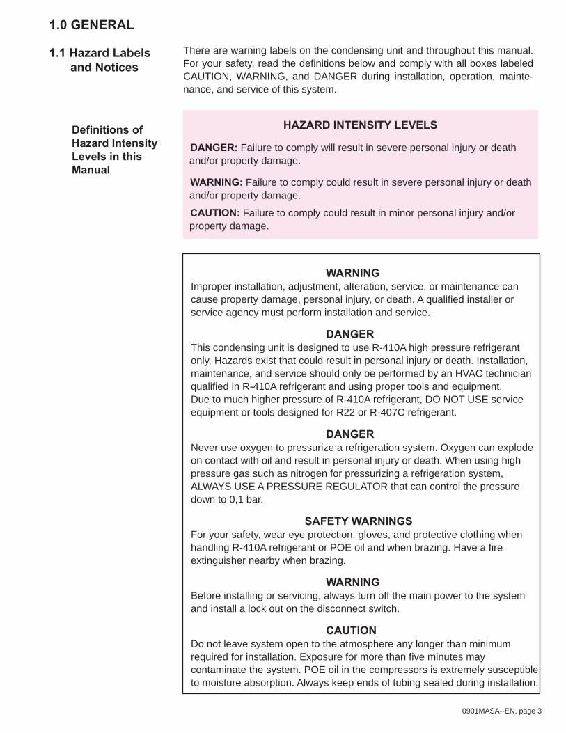
Definitions of Hazard Intensity Levels in this Manual
HAZARD INTENSITY LEVELS
DANGER: Failure to comply will result in severe personal injury or death and/or property damage.
WARNING: Failure to comply could result in severe personal injury or death and/or property damage.
CAUTION: Failure to comply could result in minor personal injury and/or property damage.
There are warning labels on the condensing unit and throughout this manual. For your safety, read the definitions below and comply with all boxes labeled CAUTION, WARNING, and DANGER during installation, operation, mainte-nance, and service of this system.
WARNINGImproper installation, adjustment, alteration, service, or maintenance can cause property damage, personal injury, or death. A qualified installer or service agency must perform installation and service.
DANGER This condensing unit is designed to use R-410A high pressure refrigerant only. Hazards exist that could result in personal injury or death. Installation, maintenance, and service should only be performed by an HVAC technician qualified in R-410A refrigerant and using proper tools and equipment. Due to much higher pressure of R-410A refrigerant, DO NOT USE service equipment or tools designed for R22 or R-407C refrigerant.
DANGERNever use oxygen to pressurize a refrigeration system. Oxygen can explode on contact with oil and result in personal injury or death. When using high pressure gas such as nitrogen for pressurizing a refrigeration system, ALWAYS USE A PRESSURE REGULATOR that can control the pressure down to 0,1 bar.
SAFETY WARNINGSFor your safety, wear eye protection, gloves, and protective clothing when handling R-410A refrigerant or POE oil and when brazing. Have a fire extinguisher nearby when brazing.
WARNINGBefore installing or servicing, always turn off the main power to the system and install a lock out on the disconnect switch.
CAUTIONDo not leave system open to the atmosphere any longer than minimum required for installation. Exposure for more than five minutes may contaminate the system. POE oil in the compressors is extremely susceptible to moisture absorption. Always keep ends of tubing sealed during installation.
0901MASA--EN, page 4
This booklet includes operation, maintenance, and service information. Before beginning any procedure, carefully review the information, paying particular attention to the warnings. All installations must be in compliance with all codes and requirements of authorities having jurisdiction.
A Model MASA outdoor condensing unit operates on R-410A refrigerant and has two independent refrigeration circuits configured in an approximate 1/3-2/3 arrangement. The Model MASA condensing unit is designed for use with a Reznor PREEVA air handler unit with a 1/3-2/3 two-circuit cooling coil. PREEVA indoor Model is SDH; outdoor Model is RDH. The Model MASA condensing unit may also be matched to a field-supplied 1/3-2/3 two-circuit evaporator coil. An air handler used with a Model MASA condensing unit must be properly matched; the evaporator coil must have freeze protection and must be equipped with properly sized thermal expansion valves.
CAUTIONThe condensing unit must be matched to an approximate 1/3-2/3 two-circuit, R-410A refrigerant coil with properly sized thermal expansion valves. Failure to properly match and/or equip the split system components will prevent the system from operating correctly and will void the manufacturer’s warranty. See Hazard Levels, page 3.
These units must be in accordance with EN 378-4 as appropriate plus all local building codes.
1.2 General Information
1.3 Installation Codes
Model MASA condensing unit must be mounted outdoors on a level surface. The supporting structure must be able to support the operating weight of the unit and maintain a level plane during continued operation. Water should drain away from the unit. Location must comply with free space clearances for unre-stricted airflow (See Paragraph 4.1) and the refrigerant piping requirements (See Paragraph 6.1.3). Avoid facing condenser coils into the prevailing wind.
2.0 LOCATION
0901MASA--EN, page 5
3.0 RECEIVINGMOVING/UNCRATING
3.1 Receiving The unit was test operated and inspected at the factory prior to crating and was in proper operating condition.If the heater has incurred damage in shipment, document the damage with the transport company and contact your supplier.
3.2 Moving The heavy gauge base of the condensing unit has forklift openings in both sides. To move a unit, use a forklift with forks that have a minimum length of 610mm.
3.3 Uncrating Immediately upon uncrating, check the rating plate to verify that the unit is suitable for the installation site. This condensing unit is designed for R-410A refrigerant only; verify that the split system air handler is for use with R-410A refrigerant.
Shipped-Separate Items
Before beginning installation, be sure that all shipped-separate options ordered are available at the site. Shipped-separate options could have been ordered with the condensing unit or the matching PREEVA air handler.
NOTE: Two liquid line filter driers are shipped loose with the condensing unit for field installation
4.0 CLEARANCES & DIMENSIONS
4.1 Clearances The condensing unit must have unrestricted airflow on the coil side and above the unit. A service clearance is required on the control side of the cabinet.
Figure 1 - minimum clearances (top view)
Coil Side (Inlet airflow through the condenser coil
must be unrestricted.)
Control Side(Service
Clearance)
OppositeControl
Side
Airf
low
Top discharge airflow must be unrestricted.Top clearance is 1524mm.
914mm
152mm
152mm
Top View1219mm
0901MASA--EN, page 6
Figure 2a - model MASA 15 and 22 dimensions
Figure 2b - model MASA 30, 37, 44, 59 dimensions
4.2 Dimensions
MASA Sizes A B
Dimensions (mm)30, 37 2184 213444, 59 2794 2743
0901MASA--EN, page 7
5.0 MOUNTINGBefore installing, check the supporting structure to be sure that it has sufficient load-bearing capacity to support the operating weight of the unit. Mounting is the responsibility of the installer.
Table 1
5.1 Weights
Approximate Operating Weight of Condensing Unit MASA Size 15 22 30 37 44 59
kg 200 209 287 317 340 350
The heavy gauge base of the condensing unit has fork lift holes and a pair of lifting holes on each corner for rigging. If lifting with a forklift, forks must have a minimum length of 610mm. If attaching rigging, insert a clevis in each set of holes for the rigging and lift using spreader bars. Lift the unit straight up with vertical force.Test lift the unit to be sure that it is secure and then lift slowly following safe lift-ing procedures. Lifting and rigging are the responsibility of the installer.
5.2 Lifting
Condensing unit may be set directly on a roof or slab. Unit must be level. Be sure to comply with clearances in FIGURE 1.5.3 Mounting
6.0 MECHANICAL
6.1 Refrigerant piping
6.1.1 Location of Piping Connections at the Condensing UnitRemove the control compartment door panel. Locate the refrigerant connections in the lower right corner. See FIGURE 3. Each circuit is shipped with a nitrogen charge and has a shutoff valve. Do not open the valves until after the lines are connected and the condenser circuits are leak tested. The entrances for the two main refrigerant circuits are identified as Circuit A and Circuit B (See FIGURE 3). Circuit A is the smaller (approximate 33%) con-denser circuit; Circuit B is the larger (approximate 67%) circuit. Also indicated, are the entrances for optional hot gas bypass circuits. If the condensing unit is equipped with a hot gas bypass on only one circuit, only one entrance will be used. If equipped with a hot gas bypass on both circuits, both entrances will be used. When connecting refrigerant lines to the condensing unit and the air handler, it is very important to make all connections so that each individual circuit is maintained.
CAUTIONDo not remove seal caps from refrigerant connections or open the service valves until ready to make permanent connection. Exposure to the atmosphere for longer than five minutes may allow moisture and dirt to contaminate the system. See Hazard Levels, page 3.
0901MASA--EN, page 8
Figure 3 Condensing Unit Refrigerant Piping
Circuit A (1/3 circuit)Piping Entrance Holes -Liquid line on the left;Suction line on the right
Electrical and Compressor
CompartmentAccess
Panel
Circuit B (2/3 circuit) Piping Entrance Holes -Liquid line on the left;Suction line on the right
R-410A Compressors(identified byCircuit A & B)
B
A
ElectricalCompartment
6.1.2 Location of Piping Connections at the Split System Evaporator CoilIt is important to identify the Circuit A and Circuit B connections at the evaporator coil before running the refrigerant lines. Circuit A on the condenser (FIGURE 3) is the smaller (33%) circuit and should be con-nected to the 33% circuit of the evaporator coil. Circuit B on the condenser (FIGURE 3) is the larger (67%) circuit and should be connected to the 67% circuit of the evaporator coil. On the evaporator coil, identify the liquid line connection at the distributor for the smaller circuit (Circuit A). Force nitrogen into the Circuit A connection and check which suction line connection corresponds to it. If the suction line connection is not identified, mark it as Circuit A. For verification, repeat the process with the larger circuit and mark the suction line con-nection as Circuit B. Refer to FIGURE 4A or 4B for illustration of a split system refrigerant piping system con-necting a MASA condensing unit to a PREEVA evaporator coil. In FIGURE 4A, the con-densing unit is higher than the evaporator coil. In FIGURE 4B, the condensing unit is lower than the evaporator coil.
0901MASA--EN, page 9
Figure 4A - Refrigerant Piping on a PREEVA Split System with the Condensing Unit Installed at a Higher Level than the Air Handler Unit
7. Field installation P or oil trap at the end of the evaporator
0901MASA--EN, page 10
Figure 4B - Refrigerant Piping on a PREEVA Split System with the Condensing Unit Installed at a Lower Level than the Air Handler Unit
0901MASA--EN, page 11
6.1.3 Refrigerant Piping Guidelines (R-410A Refrigerant) The information in this section is a guideline and is not intended to provide all of the instructions needed for designing and installing the R-410A refrigerant lines. The installer is responsible for designing the refrigerant connecting sys-tem and for complying with standard refrigerant piping procedures. Read all information in Section 6.1.3 before beginning installation of refrigerant piping. In addition to the information in the following paragraphs, these general requirements apply.
IMPORTANT: Do not bury refrigeration lines.Pitch refrigerant lines in the direction of flow at approximately 12mm per 3m.To prevent possible noise or line vibration, isolate refrigerant lines from building structure and ductwork. Use long radius for all 90° bends.Isolate suction and liquid lines from each other and from the unit cabinet.
••
•
••
CAUTION Do not leave system open to the atmosphere any longer than minimum time required for installation. POE oil in the compressors is extremely susceptible to moisture absorption. Keep ends of tubing sealed during installation. See Hazard Levels, page 3.
6.1.3.1 Type of Refrigerant Piping Refrigerant piping is field supplied. Use only clean, dehydrated refrigeration grade Type L scheduled or ACR Hard Drawn (ASTM B 280) copper tubing. Size of refrigerant line segments depends on the condensing unit size and the length and configuration of the lines. Do not determine the size of the piping by the size of the connections at the condenser or evaporator; follow the line sizing instructions in Section 6.1.3.2 below.
6.1.3.2 Refrigerant Piping Length and SizeDesign the refrigerant circuit for a minimum pressure loss by keeping the actual length to a minimum, with a minimum number of bends and fittings, and with a minimum amount of line exposed to the outdoors. Excessive suction line pressure drop will result in decreased thermal efficiency and increased power requirements. Excessive liquid line pressure drop can cause the refrigerant to flash resulting in faulty expansion valve operation. Typically, each segment of the refrigerant line should be sized for pressure loss of 1,1°C or less. Lift must also be considered when determining location and piping length. Maximum lift of the refrigerant circuit is 13.7m. Tubing size is determined separately for each of the four segments of the refrigerant piping - Circuit A liquid line; Circuit A suction line; Circuit B liquid line; and Circuit B suction line. The size of the tubing required for each segment is determined by its equivalent length. The equivalent length is the actual length of the line segment plus any fittings or accessories. If accessories (see Paragraphs 6.1.3.3 and 6.1.3.4 for required accessories) have equivalent lengths provided by the manufacturer, use that information. If equivalent length is not provided and for fittings, use the equivalent lengths in TABLE 2.
0901MASA--EN, page 12
Table 3 - Recommended Size of Refrigerant Piping for each Segment determined by the Equivalent Length
Use the worksheet on page 13, and the information in TABLE 2 and TABLE 3 to determine the line segment and circuit equivalent lengths and the size of tubing required for each line segment.
IF AN APPLICATION REQUIRES MORE THAN 18.3M OF EQUIVALENT LENGTH OF TUBING (LIQUID LINE OR SUCTION LINE) BETWEEN THE CONDENSER AND THE AIR HANDLER, CONTACT REZNOR FOR APPROVAL.
Table 2 - Fitting Pressure Loss in Equivalent Length of Straight Copper Tubing
NOTE: Liquid line filter driers provided have 1/2” connections. Add equil-valent length for filter driers plus, if liquid line is not 1/2”, add equilvalent for fittings.
*Based on copper tubing type L; a 1,1°C loss; and a maximum of 18ºC suction line (return gas) temperature and liquid line temperature of 41ºC.
**Equivalent Line Segment Length = length of fi eld-installed tubing in line segment plus equivalent length of all fi eld-installed fi ttings and accessories in line segment. For both liquid line and suction line segments, maximum recommended equivalent length is 18m.
0901MASA--EN, page 13
Circuit (fi eld-installed Liquid Line Segment and Suction Line Segment) CIRCUIT A (1/3 Circuit) CIRCUIT B (2/3 Circuit)
Line Segment (fi eld-installed refrigerant tubing)
Liquid Line Suction Line Liquid Line Suction Line
Tubing Size ________ Tubing Size ________ Tubing Size ________ Tubing Size ________Equivalent Lengths of All Accessories and Fittings in the Line Segment
Subtotal of Equivalent Lenghts of Accessories/Fittings
Plus Actual Length of Line Segment
Equals Equivalent Line Segment Length
IMPORTANT Note: Recommended maximum total equivalent line length between the condenser and evaporator coil is 18.3. For line segments longer than 18.3m equivalent length, consult Reznor for approval.
Worksheet for calculating the equivalent length of each of the four line segments
6.1.3.3 Liquid Line Piping Design the liquid lines (a line for each circuit from the condenser to the thermal expan-sion valve on the appropriate distributor at the evaporator coil) so that the pressure drop in the liquid refrigerant will not be greater than that corresponding to an approximate 0,5°C-1,1°C of subcooling. Pressure loss of 0,34 bar results in a 0,5°C loss of subcooling temperature with R-410A refrigerant. The total loss is the pressure drop loss through the piping and fittings plus any additional for lift or accessories (shutoff valve, filter, etc). Pres-sure loss due to lift is approximately 0,1 bar/m. Each liquid line requires field installation of one of the filter driers supplied with the unit (see instructions below and FIGURE 4A or 4B). Filter driers are sized for each circuit; see TABLE 4 to match the filter drier with the circuit. Also, it is highly recommended that each liquid line include a field-supplied solenoid valve and a sight glass with a moisture indica-tor. (NOTE: Do not rely on the sight glass for determining amount of refrigerant charge; see Paragraph 6.4 and subcooling and superheat checks in Paragraph 9.2.3 for determin-ing refrigerant charge. A sight glass with a moisture indicator is important because mois-ture is very detrimental to an R-410A refrigerant circuit.) Install the recommended field-supplied sight glass with moisture indicator downstream of the filter drier and upstream of the thermal expansion valve.Liquid Line Filter Driers - Two liquid line filter driers are shipped loose for field installa-tion. Match the filter drier to Circuit A or Circuit B as listed in TABLE 4.
0901MASA--EN, page 14
Table 4 - Two Liquid Line Filter Driers are Shipped Loose in the Condensing Unit
Follow the filter drier manufacturer’s instructions and install the correct filter drier in each liquid line close to the condensing unit. The arrow on the drier must be pointing toward the evaporator coil. If liquid line piping is not the same size, use a field-supplied fitting. Protect the filter drier from excessive heat when brazing.
MASA Refrigerant Circuit
R410A Liquid Line Filter Driers Shipped in the Condensing Unit for Field Installation
Thermal Expansion Valves - The thermal expansion valves are field-supplied or ordered as options with the air handler. The valves must be designed for R-410A refrigerant and sized correctly for each circuit.
If the thermal expansion valves are not pre-installed on the air handler, install the outlet of the valve to the distributor connection on the evaporator coil. (Exception NOTE: If there is an optional hot gas bypass line in the circuit, it must be allowed to connect directly into the distributor downstream of the ther-mal expansion valve; see Paragraph 6.1.3.6.) Thermal expansion valves are sized for the capacity of the circuit so be careful to match the valve to the correct circuit. Always wet wrap the valve body when brazing, but do not allow moisture to enter the tubing. Braze with the flame pointed away from the valve. Follow the instructions supplied from the valve manufacturer. After the refrigerant lines are installed and before start-up, extend the bulb from the valve in Circuit A to the Circuit A suction line. Extend the bulb from the Cir-cuit B valve to the Circuit B suction line. Comply with the valve manufacturer’s instructions on bulb placement. General recommendations are listed below.
Verify that the suction line is the correct circuit.Place bulb on suction line as close to the evaporator coil outlet as possible. Place the bulb on a straight horizontal section of suction line (if bulb must be vertical, line must be descending).
•••
CAUTIONThe thermal expansion valves must be sized to match the circuit. Failure to properly size the thermal expansion valves will prevent the system from operating properly and will void the manufacturer’s warranty. See Hazard Levels, page 3.
0901MASA--EN, page 15
3 o’clock
4 o’clock8 o’clock
9 o’clock
12
3
6
9
Position bulb flat against the surface of the suction line tubing. Secure bulb tightly and insulate.
Suction LineCross Section
Suction Line
Thermal Expansion Valve Bulb
Suct
ion
Line
ThermalExpansionValve Bulb
(Capillary tubeshould be out
the top.)
Horizontal Section of Suction Line
(preferred location)
Vertical Sectionof Suction Line
(descending flow only)
Figure 5 - Position of the Thermal Expansion Valve Bulb on the Suction Line
Never place bulb in a trap or downstream of a trap.Position bulb as shown in FIGURE 5.Bulb must have 100% contact with tubing.Secure the bulb tightly.Cover bulb with waterproof insulation.
•••••
6.1.3.4 Suction Line Piping The suction lines (lines carrying refrigerant vapor from the evaporator to the compressor) should be designed to provide minimum pressure drop and to return oil to the compressor under all load conditions. A suction line is normally sized to have a pressure drop no greater than an approximate 1,1°C of super-heat. Design and installation of the suction lines are critical to efficient operation and compressor life. Suction lines must be insulated and pitched in direction of flow. To ensure oil return, refrigerant velocity in vertical lines should be at least 7,7m/s and at least 3,8m/s in horizontal lines. If the evaporator coil is above the condensing unit, a trap is required in the suc-tion line as it leaves the evaporator. The top of the trap must be higher than the top of the evaporator. P- or oiltrap is every 3 meters required when condensing unit is above the evaporator.Isolate the liquid lines from the suction lines. Insulate the entire length of each suction line.
6.1.3.5 Brazing Connections
CAUTIONDo not leave system open to the atmosphere any longer than minimum required for installation. Exposure for more than five minutes may contaminate the system. POE oil in the compressors is extremely susceptible to moisture absorption. Always keep ends of tubing sealed during installation. See Hazard Levels, page 3.
Brazing materials must be able to withstand the high pressure of R-410A refriger-ant. A high temperature, silver phosphate type brazing with 5% or greater alloy is recommended. To prevent oxidation, purge tubing with 0,2 bar of regulated dry nitrogen while it is being brazed. Before brazing connections, check the condenser unit for leaks (See Paragraph 6.2.1). After the unit has been properly leak tested, the nitrogen remaining in the circuit can be used as part of the purge while brazing. Open the service valve as needed to release the nitrogen. Do not allow moisture to enter the system. The installer is responsible for brazing and for complying with appropriate standard refrigerant piping procedures.
CAUTIONAll brazing should be done using a 2 to 3 psig dry nitrogen purge flowing through the pipe being brazed. See Hazard Levels, page 3.
CAUTIONDo not open the service valves until after the condenser unit circuits are leak tested (See Paragraph 6.2.1.) See Hazard Levels, page 3.
CAUTIONWhen brazing, protect all painted surfaces and components from excessive heat. Wet wrap all valves but do not allow moisture to enter the tubing. See Hazard Levels, page 3.
6.1.3.6 Piping Support and InsulationComply with piping support spacing requirements in TABLE 5. Insulate the entire length of each suction line and optional hot gas bypass line(s). Insulate any portion of the liquid line that is subject to extreme temperature. To prevent vibration noise, isolate all piping from the building structure or ductwork.
Table 5 - Maximum Spacing between Pipe Supports
Maximum Spacing Between Pipe Supports for Copper TubingNominal Diameter (OD) 5/8” 7/8” 1-1/8” 1-3/8”Maximum Span 1.5m 1,8m 2,1m 2,4m
0901MASA--EN, page 17
6.2.1 Leak Test the Condensing Unit The condensing unit is shipped with a 3,4 bar nitrogen holding charge in each circuit. Install gauges to assure that the condensing unit sections of Circuit A are pressurized. If circuit is not pressurized, the nitrogen has escaped. Recharge with dry nitrogen to 10,3bar. (Maximum test pressure is 31 bar) Use soap bub-bles or other leak-detecting method. Repair as needed to ensure a leak-free circuit in the condensing unit. Repeat with Circuit B. NOTE: The nitrogen charge in the condensing unit circuits may be used during the brazing process as part of the purge. See Paragraph 6.1.3.6.
6.2.2 Leak Test the Field-Installed PipingPressurize one of the circuits with dry nitrogen to 10,3 bar. (Maximum test pres-sure is 31 bar.) Test for leaks. Repair as needed to ensure a leak-free circuit. When the circuit is successfully leak tested, allow the nitrogen to escape to the atmosphere through the pump port on the gauge manifold. Repeat with the second circuit.
6.2.3 Pressure test of MASA and field installed pipingFor PED requirements the installation needs to be pressure tested at 110% of the design pressure. The MASA condensor unit was pressure tested in the fac-tory. It is forbidden to redo a pressure test on the MASA unit as severe damage wlll occur.
6.2.3.1 High pressure side pipesThe field installed piping should be pressure tested. If the design pressure of the pipes is less than 41,4 bar, manual resetable pressure switch with a setting of the design pressure or less is needed in the field installed piping.6.2.3.2 Low pressure side pipesThe field installed piping should be pressure tested at 28.2 bar.6.2.3.3 Pressure test for field installed pipingDuring the pressure test, the shut-off valves of the MASA unit must be closed. Only the field installed piping can be pressurized. It will be necessary to put a charge point in the field installed piping.
Evacuate one circuit at a time. Use a vacuum pump and micron gauge. Each circuit must be evacuated to hold a 10 mbar vacuum. Vacuum must be pulled on both the discharge (high) and suction (low) side. Do the suction side first; and the compressor discharge side second. To establish that a circuit is leak-free and moisture-free, a standing vacuum test is recommended. Close off the valve to the vacuum pump and observe the micron gauge. If the vacuum gauge does not rise above 10 mbar in one minute, the evacuation should be complete. If vacuum gauge does rise above 10 mbar in one minute, evacuation is incom-plete or the system has a leak. Repeat as needed until evacuation is complete. The evacuation process must be done on each circuit.NOTE: Evacuation will not remove moisture from POE oil. Moisture must be prevented from getting in the oil.
6.2 Leak & Pressure Test of the Refrigerant Circuits
6.3 Evacuate the Circuits
DANGER : Isolate the MASA unit during the pressure test of the field installed piping by closing the shut-off valves (2 per circuit) at 45.5 bar.
0901MASA--EN, page 18
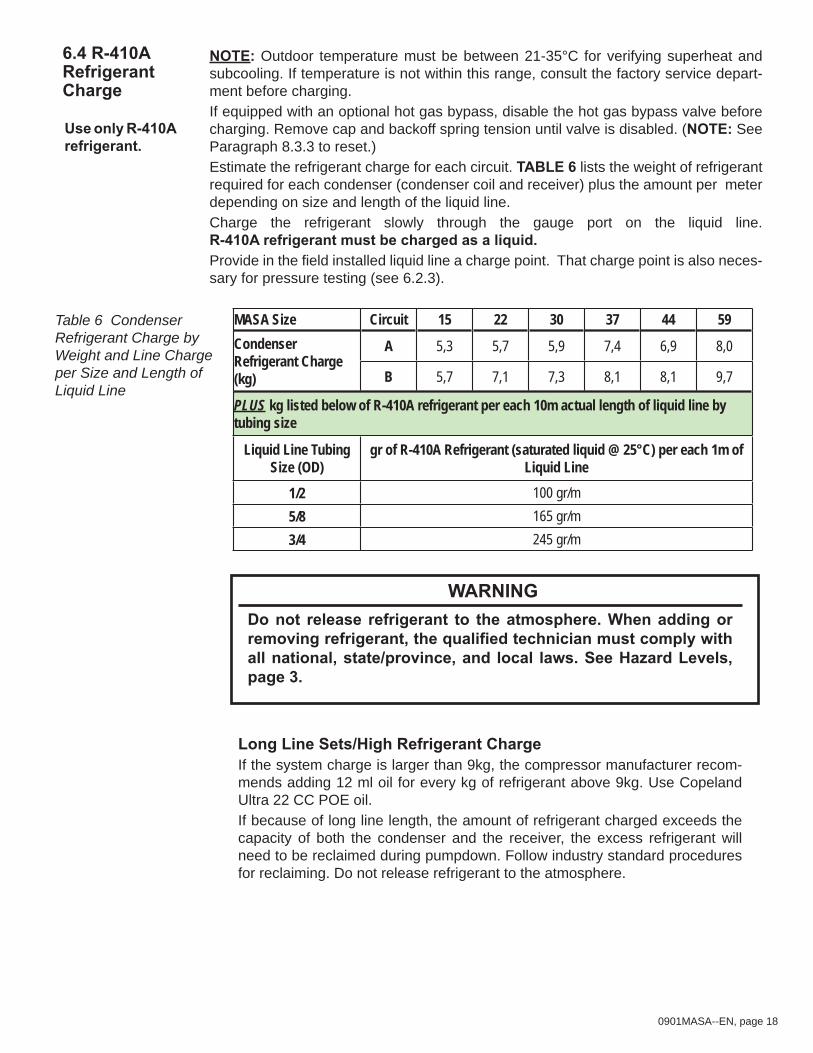
NOTE: Outdoor temperature must be between 21-35°C for verifying superheat and subcooling. If temperature is not within this range, consult the factory service depart-ment before charging.If equipped with an optional hot gas bypass, disable the hot gas bypass valve before charging. Remove cap and backoff spring tension until valve is disabled. (NOTE: See Paragraph 8.3.3 to reset.) Estimate the refrigerant charge for each circuit. TABLE 6 lists the weight of refrigerant required for each condenser (condenser coil and receiver) plus the amount per meter depending on size and length of the liquid line. Charge the refrigerant slowly through the gauge port on the liquid line. R-410A refrigerant must be charged as a liquid. Provide in the field installed liquid line a charge point. That charge point is also neces-sary for pressure testing (see 6.2.3).
6.4 R-410A Refrigerant Charge
Use only R-410A refrigerant.
Table 6 Condenser Refrigerant Charge by Weight and Line Charge per Size and Length of Liquid Line
PLUS kg listed below of R-410A refrigerant per each 10m actual length of liquid line by tubing size
Liquid Line Tubing Size (OD)
gr of R-410A Refrigerant (saturated liquid @ 25°C) per each 1m of Liquid Line
1/2 100 gr/m5/8 165 gr/m3/4 245 gr/m
WARNINGDo not release refrigerant to the atmosphere. When adding or removing refrigerant, the qualified technician must comply with all national, state/province, and local laws. See Hazard Levels, page 3.
Long Line Sets/High Refrigerant ChargeIf the system charge is larger than 9kg, the compressor manufacturer recom-mends adding 12 ml oil for every kg of refrigerant above 9kg. Use Copeland Ultra 22 CC POE oil. If because of long line length, the amount of refrigerant charged exceeds the capacity of both the condenser and the receiver, the excess refrigerant will need to be reclaimed during pumpdown. Follow industry standard procedures for reclaiming. Do not release refrigerant to the atmosphere.
0901MASA--EN, page 19
Supply VoltageThe electric supply to the unit must meet stringent requirements for the system to operate properly. Voltage supply should be within ±10% or as stated on the rating plate. Follow instructions below to check.
CAUTIONIf this condensing unit is allowed to operate on an electric supply that is not within the specified tolerances, the product warranty shall be void. See Hazard Levels, page 3.
If the power supply is not within these tolerances, contact the power company prior to operating the system.
Check Voltage Supply - See voltage use range on the rating plate. Measure (and record) each supply leg voltage at all line disconnect switches. Readings must fall within the allowable range.
Compressor models such as TFD extentions have an internal line break motor protector. This protector disconnects all three legs of the motor from power in case of an overload or overtemperature condition.
Compressor models such as TWD extentions have a motor protection system with an external electronic control module with four thermistors. The module will trip and remain off for 30 minutes if the motor exceeds a preset value.
7.2 Supply Wiring
7.0 ELECTRICAL & WIRING7.1 General
The electrical installation may only be carried out by an appropriately qualified person current to IEE regulations. The supply line to the air cooled condensing unit should include a main switch. The minimum distance between the contacts must be more than 3mm. All electrical connections should be made in the electrical control department (see fig. 3). Screw type main terminals for installer are provided. Connection should be in accordance with the terminal marking and the wiring diagram affixed to the unit. Each unit has a wiring diagram in the electrical compartment (see figure 6).
NOTE : turning off power to the module will result into immediate reset. The module has a 30 minutes time delay to allow the scrolls to cool down after the motor temperature limit has been reached. Restarting the compressor sensor may cause a destructive temperature build-up in the scrolls. For this reason module power must never be switched with the control circuit voltage!
Thermostat location The siting of the room thermostat is important. It should not be fitted on a warm wall or surface.Avoid location in draughty areas or where it may be influenced by heat sources e.g. the sun, process plant, etc. The thermostat or temperature sensor should be mounted on a vibration free surface and mounted about 1,5 meters above floor level Follow the thermostat manufacturers fitting instructions.
0901MASA--EN, page 20
Compressor Wiring - A 3-phase scroll compressor must be phased correctly or com-pressor will operate in reverse. Since there is a chance of unknowingly connecting the power in such a way as to cause rotation in reverse, it is important to check this on startup.
Before initial startup, connect refrigerant pressure gauges to the compressor suction and discharge lines. At startup, observe the gauges. If the suction pressure rises and discharge pressure drops, the compressor is operating in reverse and should be shut down. (After several minutes of operation in reverse, the compressor’s internal protector will trip. If a compressor is repeatedly allowed to restart and run in reverse, the compressor will be permanently damaged.) Turn off the power and switch the 3-phase line voltage wiring connections before restarting the unit.
CAUTIONBe sure to connect pressure gauges to the suction and discharge lines before startup so that compressor rotation can be checked immediately. Scroll compressors will be destroyed if operated in the wrong direction. See Hazard Levels, page 3.
0901MASA--EN, page 21
Figure 6a - Wiring Diagram MASA 15, 22
0901MASA--EN, page 22
Figure 6b - Wiring Diagram MASA 30, 44
0901MASA--EN, page 23
Figure 6c - Wiring Diagram MASA 59
0901MASA--EN, page 24
8.0 CONTROLS & OPERATIONS
8.1 Digital control system
An FX07 platform was programmed to work properly with a PREEVA (SDH or RDH) and a MASA appliance and can be supplied as option. An anti-short cycling protection for the compressors is integrated in the FX07. When using another digital platform, it is necessary to order the anti-short cycle module option. If not,an anti-short cycling of 5 minutes must be programmed in the controller.
8.2 Analog control system
A 3 stage (230V) cooling thermostat must be used. The anti-short cycle relays must be integrated in the MASA unit to protect the compressor. This is an option which needs to be specified at the moment of ordering the unit.
8.3.1 High Pressure CutoffThe high pressure cutoff control is located in the discharge line as it exits the compressor. If the discharge pressure exceeds the high pressure cutoff setting (40,2±0,7bar), the control will stop compressor and condenser fan operation. The high pressure cutoff control is a manual reset device. It can be reset when the pressure drops below the differential setting (28±1bar)). Correct the prob-lem before resetting the device to restart operation of the system.
8.3.2 Low Pressure CutoffThe low pressure cutoff control is located in the suction line as it enters the compressor. If the suction pressure drops below the low pressure cutoff setting (2,4±0,5bar), the control will stop compressor and condenser fan operation. The low pressure cutoff control will automatically restart operation when the suction pressure goes above 3,4±0,5bar.
8.3.3 Compressor Protection (option)Optionaly the condensing unit has a five-minute anti-short cycle timer on com-pressor operation.
8.3.4 Crankcase HeatersEach scroll compressor in the condensing unit has a band-type crankcase heater. Crankcase heaters must always have been energized for at least 24 hours prior to operating the compressor.
8.3 Other Compressor and Refrigerant Controls
Check the wiring dia-gram on the unit to determine if it has optional controls.
NOTE: Standard with Reznor PREEVA with digital FX07 controls.
0901MASA--EN, page 25
9.0 FINAL CHECKS & START-UP
Assumptions: All connections are made; actual startup is imminent. Site is clean; all excess supplies, scraps, and debris have been removed.
WARNING:To prevent injury or death due to electrocution or contact with moving parts, lock disconnect switch open when doing checks prior to startup. See Hazard Levels, page 3.
9.1.1 Checklist Prior to Start-upCheck Clearances. All clearances must be as illustrated in Para-graph 4.1. Electrical Checks
Verify the electrical supply matches voltage rating of the unit. (Refer to the rating plate.) Check the wiring for loose connections or damaged wire. Be sure to check the black molded plastic plug or terminal block on the compressor. Tighten plugs and connections. Replace damaged wiring. (See Paragraph 7.3 for replacement wiring requirements.)Check all field wiring against the wiring diagram. Be sure all field-installed controls are in place. Be sure that wire gauges are as required for the electrical load. All field wiring must comply with the National Electric Code and local regulations.Be certain that the electrical entrances are sealed against the weather.Check that fuses or circuit breakers are in place and sized correctly.
Be certain the manual reset on the compressor high pressure cutoff switch is reset.Check free rotation of condenser fan(s). Remove all shipping supports and restraints.
Check field-installed refrigerant lines:Verify that the filter driers shipped with the unit are installed prop-erly in the correct circuits. Verify that the refrigerant line for 1/3 circuit A on the condenser is connected to 1/3 circuit A on the evaporator. Check that 2/3 circuit B on the condenser is connected to 2/3 circuit B on the evaporator. Verify that the thermal expansion valve bulbs are attached prop-erly to the correct suction line. See Paragraph 6.1.3.3.Verify that the system has been properly evacuated and charged with R-410A refrigerant.
In addition, verify that all startup checks in the air handling manual have been completed.
□
□□
□
□
□
□
□
□□□□
□
□
□
□
IMPORTANTOn initial start-up, fill-in the CONDENSER STARTUP FORM on page 40. Completed form may be required for warranty.
9.1 General Comments
0901MASA--EN, page 26
CAUTIONCrankcase heaters must be allowed to warm up for at least 24 hours prior to startup. Disable cooling controls before turning on power to warmup crankcase heaters. See Hazard Levels, page 3.
Assumptions: All pre-startup checks have been made and crankcase heaters have been allowed to warmup for at least 24 hours.
9.2.1 Power Supply Voltage PhasingConnect refrigerant pressure gauges to the suction and discharge lines of the compressors and an electric meter to the power supply.
CAUTIONBe sure to connect pressure gauges to the suction and discharge lines before system start-up so that compressor rotation can be checked immediately. Scroll compressors will be destroyed if allowed to operate in the wrong direction. See Hazard Levels, page 3.
Record the ambient temperature. Adjust the system controller so that a call for cooling exists. NOTE: If the system has digital controls, outdoor ambient lockouts may prevent mechanical cooling. Temporarily override lockouts by lowering the cooling setpoint. (If installing a PREEVA air handler, refer to the dig-ital programmable control section in the instruction manual.) When test-ing is complete, reset the controller.
Because it is a possible to unknowingly connect 3-phase power in such a way as to cause the scroll compressor to rotate in reverse, it is very important to check this on startup. Immediately at startup, observe the gauges. If the suction pres-sure rises and discharge pressure drops, the compressor is oper-ating in reverse and must be shut down. Turn off the power and switch the 3-phase line voltage wiring connections before restart-ing the unit.
If allowed to operate for several minutes in reverse, the compres-sor’s internal protector will trip. If a compressor is repeatedly allowed to restart and run in reverse, the compressor will be permanently damaged.
□
□
□
9.2 Start-up
Note: Redo startup procedures when the cooling season begins.
Important note
0901MASA--EN, page 27
9.2.2 Operating Sequence
For a three-stage cooling sequence, the operating sequence is #1 (Circuit A Compressor); then #2 (Circuit B Compressor); and then #1 and #2 (both Circuit A and Circuit B Compressors).
9.2.3 Refrigerant ChargePREPARATION:
To verify superheat and subcooling, outdoor temperature must be between 21-35°C. If temperature is not within this range, consult the factory service department before charging.Operate for 30 minutes for system to stabilize. Check BOTH refrigerant circuit A and circuit B; isolate each cir-cuit before measuring superheat and subcooling.If the circuit has an optional hot gas bypass valve, disable it before measuring superheat and subcooling. To disable, remove cap and backoff spring tension. Be sure to reset after checking (See Paragraphs 8.3.3 and 9.2.4).
9.2.3.1 Check SUBCOOLING Measure and record temperature and pressure of the liquid line at the condenser coil outlet.
STEP 3) Subtract Measured Temperature (STEP 1) from
Temperature from Conversion Chart (STEP 2)
________°C - ________°C = ________K degrees of
Subcooling
Recommended subcooling with outdoor temperature range of 21-35°C is 7-8 K.Too much subcooling indicates a refrigerant overcharge. To reduce the subcooling, remove excess refrigerant. Too little subcooling indi-cates a refrigerant undercharge. To increase subcooling, slowly add R-410A refrigerant.
WARNINGDo not release refrigerant to the atmosphere. When adding or removing refrigerant, the qualified technician must comply with all national, state/province, and local laws.
•
□
□□
□
□
IMPORTANTAll refrigeration checks MUST be made by a refrig-eration technician qualified in R-410A refriger-ant. Equipment and tools MUST be designed for R-410A refrigerant.
0901MASA--EN, page 28
9.2.3.2 Determine SUPERHEATMeasure and record temperature (insulate probe from surrounding air tem-perature) and pressure in the suction line at the compressor inlet.
STEP 3) Subtract Measured Temperature (STEP 1) from
Temperature from Conversion Table (STEP 2)
________°C - ________°C = ________K degrees of
Superheat
Recommended superheat at is 4.5-6.7°C.Typically, too much superheat indicates that the evaporator coil is undercharged. Too little superheat typically indicates that the evap-orator coil is overcharged and may potentially flood liquid refriger-ant to the compressor. To reduce the superheat, adjust the thermal expansion valve by turning the adjusting stem counterclockwise. To increase the superheat, adjust the thermal expansion valve by turning the adjusting stem clockwise.
Assumptions: All checks have been successfully performed and the system is operating properly. All panels and doors are secure. The area has been cleared of any excess supplies, scrap, and debris.
Check that the information on page 44 has been completed.After startup, put this manual with completed startup form (page 41), the warranty form, and any other instructions provided with the unit in the Literature Bag. Return the “Literature Bag” to the low voltage compartment of the unit or give it to the building owner for safe keeping.
□
9.3 After Startup:
0901MASA--EN, page 29
This condensing unit will operate with a minimum of maintenance. To ensure long life and satisfactory performance, an air conditioning system that is oper-ating under normal conditions should be inspected according to the Mainte-nance Schedule below. If in an environment where an unusual amount of dust or soot or other impurities are present, more frequent inspection is recom-mended. The procedures in the schedule below are only for the condensing unit. Refer to and comply with the maintenance schedule for the Reznor PREEVA unit or other air handler with evaporator.
Beginning of the cooling season or more frequently in year-round cooling climate:
Inspect the wiring for any damaged wire. Replace damaged wiring.Inspect the condenser fan. Clean as needed. See Paragraph 10.3.Inspect/clean condenser coil. See Paragraph 10.4.Check compressor operation. See Paragraph 10.5.Check refrigerant pressure and temperatures (both superheat and subcool). These measurements must be taken when the system is in operation. See Paragraph 10.5.
□□□□□
Figure 7 - Electrical Compartment showing Control Locations
10.1 General
10.2 Maintenance Schedule
NOTE: If replacement parts are required, use only factory-authorized parts. For information, call your supplier.
WARNINGTurn off the power before performing all maintenance procedures (except to check subcooling & superheat. Lock disconnect switch in OFF position. See Hazard Levels, page 3.
Electrical and Compressor
CompartmentAccess
Panel
Top (removed for clarity)
Line Voltage EntranceControls Entrance
R-410A Compressors(identified byCircuit A & B)
B
A
10.0 MAINTENANCE & SERVICE
0901MASA--EN, page 30
Check condenser fans. Carefully clean debris and dirt from guards, fan blades and motors. If any parts need to be replaced, use only factory-authorized replace-ment parts.
10.3 Condenser Fan(s) Maintenance
10.4 Condenser Coil Maintenance
Unless equipped with an optional coil guard, the entering airflow side of the con-denser coils can be reached for cleaning without removing any components. If there is a coil guard, remove the screws holding the guard.
Figure 8 - Condenser Fan Rotation and Fan Blade Spacing from Top Edge of Fan Orifice
Figure 9 - Remove the Optional Coil Guard
Fan rotation is counterclockwise.Top View
Side View
25-38mm maximum distance from top of fan blade down to top edge of fan orifice in cabinet top
Motor
Condenser TopFan Blade
Torque blade setscrew to 13,6 ±0,2Nm.
Coil Guard(option)
Screwswith washersacross the top
Screwsacross the bottom
0901MASA--EN, page 31
Instructions for Cleaning Coil1) Verify that the electrical power has been turned off and the disconnect
switch locked.2) Use a soft brush to remove any dirt and debris from the coil. 3) Spray with cold or warm (not hot) water and a cleaning solution (non-acid
based coil cleaner is recommended). Due to possible damage to the coil, do not use high pressure spray.
4) When clean, rinse with cool, clean water.If additional cleaning is required or if the coil must be removed for any reason, consult the factory. Be prepared to provide rating plate and installation infor-mation.
DANGERThe refrigeration circuits are high pressure systems. Hazards exist that could result in personal injury or death. It is therefore required that the removal and installation of this scroll compressor be performed by a technician qualified in R-410A refrigerant. See Hazard Levels, page 3.
DANGERNever use oxygen to pressurize a refrigeration system. Oxygen can explode on contact with oil and could result in personal injury or death. When using high pressure gas such as nitrogen for this purpose, ALWAYS USE A PRESSURE REGULATOR that can control the pressure down to 0,1 bar. Failure to use a regulator will result in extremely high pressure which could exceed the burst pressure of the compressor or other system components and result in personal injury or death. See Hazard Levels, page 3.
WARNINGSFor your safety, wear eye protection, gloves, and protective clothing when handling refrigerant and oil and when brazing. Have a fire extinguisher nearby. See Hazard Levels, page 3.
Compressor HandlingDo not lift compressor by copper tubing. To prevent internal damage, compres-sors must ALWAYS be held upright. The following instructions include major points of consideration that will ensure proper installation and protect you from potential personal injury. Use the fol-lowing 13 steps as a checklist, taking each item in order before proceeding to the next. If more information is required, contact your Reznor supplier.
10.5 Compressor Maintenance and Replacement
0901MASA--EN, page 32
WARNINGTo avoid electrical shock or damaged compressor, power to the compressor(s) MUST RE-MAIN OFF during performance of Steps 1 through 9 below. LOCK DISCONNECT SWITCH OFF (open). See Hazard Levels, page 3.
Table 7 Replacement Scroll Compressors for R-410A Refrigerant
Step 1. Verify Replacement R-410A Compressor ApplicationVerify that the replacement compressor is identical to the model being replaced. All components of the manufacturer’s Model No. must be identi-cal. System components are matched to the compressor. Replacing a com-pressor with a model other than the Thomas & Betts (Reznor) specified replacement will void the product warranty.
Step 2. Determine Cause of Initial Failure and Remove the CompressorIn order to prevent a second failure, the cause of the original failure must be determined. Identify the cause and make the necessary repairs.
*Model No. of replacement R410A scroll compressor must be identical to the one removed including the “E” (ZP39KxExxx) which indicates POE compressor oil.
IMPORTANT: Model of replacement compressor and Model of factory-installed compressor that was removed must be identical.
0901MASA--EN, page 33
CAUTIONDO NOT LIFT compressor by copper tubing; damage will occur. Compressor must remain upright. See Hazard Levels, page 3.
WARNINGWear eye protection, gloves, and protective clothing when handling refrigerant, POE oil, and when brazing. See Hazard Levels, page 3.
a) BEFORE REMOVING THE FAULTY COMPRESSOR, remove R-410A refrigerant charge using proper recovery procedures. This is a scroll com-pressor. Be sure to remove refrigerant from both the high side and the low side.
WARNINGDo not release refrigerant to the atmosphere. When adding or removing refrigerant, the qualified technician must comply with all national, state/province, and local laws.
b) Disconnect wires. Compressor wiring is connected either using a black molded plastic plug or wire terminals. Either remove the plug from the compressor or disconnect the wires.
c) Open access ports so that pressure does not build up in the system. Before unbrazing, cut the suction and discharge tubing with a tubing cutter.
WARNINGHave a fire extinguisher near. The compressor contains oil. There is a risk of fire when unbrazing stubs. See Hazard Levels, page 3.
Use a high temperature torch to disconnect the suction line and the dis-charge line from the compressor.
d) Remove the mounting bolts and the compressor. Save the mounting hardware to attach the grommets and sleeves shipped with the replace-ment compressor.
e) To test for acid and to assure excess oil does not remain in the circuit, remove oil from the failed compressor. Measure the amount of oil.
CAUTIONIn addition to the required eye protection and gloves, care should be taken in handling POE oil because it may cause damage to certain plastics and roofing materials. See Hazard Levels, page 3.
If the oil taken from the compressor and measured is found to be significantly lower than listed in TABLE 10, clean the excess oil through use of suction and liquid line filter driers. Beginning in Step 4, follow the same procedure as for burnout cleanup.
0901MASA--EN, page 34
Table 8 - Compressor Oil Charge
Use an acid test kit to check the oil for acid. If acid is found, beginning in Step 4, follow procedures indicated for burnout cleanup. Dispose of oil and compressor using an approved environmentally safe disposal method.
Step 3. Mount the Replacement CompressorDo not remove the dust cover or rubber shipping plugs until all other sys-tem connections are complete (i.e. new liquid line filter drier(s) installed and all tubing changes made - see Steps 4 and 5). The amount of time the compressor is open to the atmosphere must be kept to a minimum.Use the new mounting grommets and sleeves that are shipped with the compressor to mount it. The sleeves will prevent over compression of the grommets. Re-use the mounting bolts from the compressor that was removed. The mounting bolts will bottom out when tight.
Step 4. Install New Filter Driers (Select procedure that applies.)IF the oil measured in Step 2 was not significantly less than the amount shown in TABLE 10 or the test for acid in Step 2 did NOT indicate burn-out , install a new R-410A refrigerant liquid line filter drier. The filter drier must be rated for no less than 41bar and be the proper size for the cir-cuit. Because R-410A refrigerant requires POE oil which absorbs mois-ture quickly, it is important to change the filter drier any time the circuit is opened. It is recommended to use a tubing cutter when cutting out a filter drier as the desiccant absorbs and holds moisture better when it is cool. Heat from a torch may cause moisture to leave the filter and be absorbed in the oil. Continue to Step 5.IF the oil measured in Step 2 was significantly less than shown in TABLE 10 or the test for acid in Step 2 did indicate compressor burnout, do the following:a) Install a liquid line filter drier. If there is acid, install an acid removing
filter drier. Size the acid-removing filter drier at least one capacity size larger than normally required for the circuit.
b) Install a temporary filter drier in the suction line. When there is acid, a 100% activated alumina suction filter drier is recommended. The suc-tion line drier should be sized properly for the circuit and have a service access fitting to monitor pressure drop across the drier. (NOTE: Suction line filter drier must be removed after 72 hours of operation.)Step 12 includes the remaining procedures required for cleanup of a burnout. Continue to Step 5.
Step 5. Braze on Suction and Discharge LinesComply with the brazing instructions in Paragraph 6.1.3.6.
□
□
□
MASA Size 15 22 30 37 44 59Circuit A B A B A B A B A B A BCompressor ZP20K ZP39K ZP29K ZP57K ZP39K ZP83K ZP54K ZP103K ZP57K ZP120K ZP83K ZP154KPOE Oil (g.) 964 1077 593 1474 1077 1588 1758 3005 1474 3005 1588 3005
0901MASA--EN, page 35
Step 6. Check Circuit for LeaksComply with instructions in Paragraph 6.2.1.
Step 7. Evacuate the CircuitComply with instructions in Paragraph 6.3.Continue and/or repeat Steps 6 and 7 until evacuation is complete.
CAUTIONDo not use the replacement compressor as an evacuation assist and never apply voltage to a compressor while it is in a vacuum. See Hazard Levels, page 3.
Moisture and air are harmful to the system because they increase the con-densing temperature, raise the discharge gas temperature, cause forma-tion of acids, and cause oil breakdown.
CAUTIONDo not leave a circuit open to the atmosphere any longer than minimum required for installation. POE oil in the compressor is extremely susceptible to moisture absorption. Evacuation will
not remove moisture from POE oil. See Hazard Levels, page 3.
Step 8. Check the Electrical SystemAfter the system has been evacuated, reconnect the electrical plug to the compressor or the wires to the compressor terminals. It is a normal prac-tice to replace all starting components any time a compressor is changed.
WARNINGDo not apply voltage to the compressor when the plug is removed or terminals disconnected. See Hazard Levels, page 3.
Crankcase HeaterConnect the crankcase heater. The crankcase heater is energized continu-ously and is extremely important to proper compressor operation and long life. The crankcase heater must be energized for at least 24 hours before start-ing the unit or after a power outage of more than 8 hours. Be sure to disable cooling controls before turning on power to warmup crankcase heaters.
CAUTIONCrankcase heaters must be allowed to warm up for at least 24 hours prior to startup. Disable cooling controls before turning on power to warmup crankcase heaters. See Hazard Levels, page 3.
Step 9. Charge the System (R-410A refrigerant)Charge the circuit according to the information in Paragraph 6.4. R-410A refrigerant must be charged as a LIQUID.
□
□
□
□
0901MASA--EN, page 36
Step 10 . System StartupConnect refrigerant pressure gauges and electric meters. Refer to Start-Up Paragraph 9.2 and perform all procedures required prior to checking sub-cooling and superheat which is done in Step 11.
CAUTIONBe sure to connect pressure gauges to the suction and discharge lines before start-up so that compressor rotation can be checked immediately. Scroll compressors will be destroyed if allowed to operate in reverse. See Hazard Levels, page 3.
Step 11. Check Subcooling and Superheat Refer to Start-Up Paragraph 9.2 and follow instructions for checking sub-cooling and superheat.
WARNINGDo not release refrigerant to the atmosphere. When adding or removing refrigerant, the qualified technician must comply with all national, state/province, and local laws.
Step 12. (Select the procedure that applies.)IF the oil measured in Step 2 was significantly less than in TABLE 10 or the acid test in Step 2 indicated a burnout, do the following: a) Operate the unit for several hours. Check the pressure drop through the
temporary suction line filter drier. If the pressure drop exceeds 0,5barg, recover the refrigerant, replace the suction line filter drier with the same type as removed, replace the liquid line filter drier, evacuate the circuit, and re-charge with the recovered refrigerant (see Paragraph 6.4). Con-tinue to monitor the pressure drop through the suction line filter drier and repeat the process above until the pressure does not exceed 0,5barg after several hours of operation. (NOTE: System must be allowed to run no more than 72 hours with a suction line filter drier.)
b) Allow the system to operate for 4-8 hours. Recover the refrigerant and take an oil sample. Retest the oil for acid.
c) If the test for acid is negative, remove the suction line filter drier, replace the liquid line drier, evacuate, and re-charge the system with the recov-ered refrigerant. If the test indicates acid, replace both the liquid line filter drier and the suction line filter drier and repeat b) and c).
CAUTIONAfter cleanup is complete, remove the suction line filter drier. See Hazard Levels, page 3.
d) Verify subcooling and superheat (refer to Start-Up Paragraph 9.2).e) When the system is operating properly, remove the gauges. IF the oil measured in Step 2 was not significantly less than that shown in TABLE 10 or the acid test in Step 2 did not indicate a com-pressor burnout, continue to the review in Step 13.
Step 13 . Review ALL Steps to ensure that nothing was overlooked.
□
□
□
□
0901MASA--EN, page 37
IMPORTANT:
Do not release refrigerant to the atmosphere! If required service procedures include the adding or removing of refrigerant, the service technician must comply with all national, state or province, and local laws.
10.6 Troubleshooting Chart
SYMPTOM POSSIBLE CAUSE REMEDYA. Compressor will not start.
1. Power off, loose electrical connections, or fuse open. 1. Check disconnect switch, fuses, and wiring. Replace parts or repair as necessary.
2. Compressor contactor not closing. 2. Check voltage to contactor coil, transformer, slave relay, and system. Replace parts as necessary.
3. Internal compressor thermal overload open. 3. If compressor is hot, allow 2 hours to cool. See D. below.
4. Compressor defective. 4. Check compressor for electrical failure. Compressor may be seized; check refrigerant. If necessary, replace compressor.
5. High or low pressure switch open or defective. 5. If manual reset (high pressure), reset switch. (Switch opens at 40bar and will not reset above 32 bar.) If auto reset (low pressure) does not reset and everything else is OK, replace switch.
B. Compressor starts but cuts out on low pressure (low pressure switch activates at 45 psig.)
1. Low refrigerant charge. 1. Check subcooling and superheat. (See Paragraph 9.2)2. Airfl ow restricted. 2. Check for dirty evaporator coil, dirty fi lters, closed dampers, iced evaporator coil, or improper belt.
Check motor amps. Check duct design.
3. Restriction in refrigerant line. 3. Check refrigerant pressure; check and adjust thermal expansion valve. If not functioning properly, check for pressure drop across the fi lter drier.
4. Defective low pressure switch. 4. Check calibration of switch.C. Compressor starts but cuts out on high pressure switch.
1. Refrigerant overcharge. 1. Check subcooling and superheat. (See Paragraph 9.2)2. Condenser fan motor defective. 2. Check fan motor(s).
4. Air or non-condensables in system. 4. Check high side equalized pressure reading with equivalent outdoor temperature.
5. Defective high pressure switch. 5. Check calibration of switch.6. Restriction in discharge or liquid line. 6. Check refrigerant line pressures, check thermal expansion valves.
D. Compressor cuts out on thermal overload.
1. Low voltage. 1. Check voltage.2. Sustained high discharge pressure. 2. Check running amperage and conditions described in H.3. High suction and discharge pressures. 3. Check thermal expansion valve setting. Check for non-condensables in the system.
4. Defective compressor overload. 4. If compressor is hot, allow compressor to cool for two hours. Recheck for open circuit.
5. Compressor operating in reverse. 5. Switch the 3 phase line voltage wiring connections.6. Improper refrigerant charge. 6. Check subcooling and superheat. (See Paragraph 9.2)7. Bearings or pistons too tight. 7. Check for low oil level.8. Allow time for compressor to cool. 8. Check dome temperature of the compressor.
E. Noisy compressor 1. Refrigerant overcharge. 1. Check subcooling and superheat. (See Paragraph 9.2)2. Compressor operating in reverse. 2. Switch the 3 phase line voltage wiring connections.3. Liquid fl oodback. 3. Check thermal expansion valve setting. Check for refrigerant overcharge. Check subcooling and
superheat. (See Paragraph 9.2).
4. Tubing rattle. 4. Dampen tubing vibration by taping or clamping. Carefully bend tubing away from contact where possible.
5. Compressor defective. 5. Check internal parts. Replace parts or compressor as needed.
0901MASA--EN, page 38
SYMPTOM (cont’d) POSSIBLE CAUSE (cont’d) REMEDY (cont’d)F. High suction pressure 1. Excessive load on evaporator coil. 1. Check for high entering wet bulb temperature. Check for excessive air.
2. Compressor is unloaded. 2. Check head pressure; check thermal expansion valve if not functioning properly; check pressure drop across fi lter drier.
3. Expansion valve not secured to suction line or valve defective.
3. Check operation of the thermal expansion valve. Ensure bulb is secure and insulated (See Paragraph 6.1.3.4).
G. High discharge pressure. 1. Thermal expansion valve setting. 1. Check thermal expansion valve and superheat.
3. Refrigerant charge. 3. Check subcooling and superheat. See Paragraph 9.2.
4. Condenser fan motor defective. 4. Check operation of condenser fan motor(s).5. Non-condensables in the system 5. Clean the circuit.
H. Suction pressure is too low.
1. Refrigerant undercharge. 1. Check pressures and subcooling. See Paragraph 9.2.
2. Blower running backward. 2. Interchange any two wires of 3 phase wiring connections.
3. Loose blower, pulley, or belts. 3. Check air handler drive pulley alignment and belt tension.
4. Defective or improperly adjusted expansion valve. 4. Check superheat (Paragraph 9.2) and thermal expansion valve.
5. Dirty fi lter. 5. Check fi lter and evaporator coil. Clean or replace as needed.
6. Too little air fl ow or low entering air temperature. 6. Check airfl ow and entering air wet bulb conditions.
7. Restriction in suction or liquid line. 7. Check refrigerant circuit for restriction. J. Head pressure too low. 1. Insuffi cient refrigerant charge. 1. Check superheat and subcooling (Paragraph 9.2). Check for a leak.
2. Defective or improperly adjusted expansion valve. 2. Check superheat and thermal expansion valve.
3. Low suction pressure. 3. See “H. Suction pressure too low” above.4. Defective compressor. 4. See “F. High suction pressure” above.
K. Compressor short cycles. 1. Thermostat location or malfunction. 1. Check thermostat/control.2. Improper refrigerant charge. 2. Check subcooling and superheat (Paragraph 9.2).3. Defective high or low pressure control. 3. Check high or low pressure switch. Replace as needed.
4. Liquid fl oodback. 4. Possible tight bearings.5. Defective expansion valve. 5. Check thermal expansion valve and superheat.6. Poor air distribution. 6. Check ductwork for recirculating.7. High discharge pressure. 7. See “G. High discharge pressure.” above.8. Leaking discharge valves in compressor. 8. See “F. High suction pressure” above.
L. Running cycle is too long or unit operates continuously.
1. Refrigeration undercharged. 1. Check subcooling. (Paragraph 9.2)2. Dirty fi lter or evaporator coil. 2. Check fi lter, coil, and airfl ow.3. Dirty or clogged condenser coil. 3. Check coil and airfl ow.4. Air or other non-condensables in system. 4. Check equalized high side pressure with equivalent outdoor temperature.
5. Defective compressor. 5. See “F. High suction pressure” above.6. Restriction in suction and liquid line. 6. Check for restrictions in refrigerant circuit.7. Control contacts stuck. 7. Check wiring.
M. Supply air temperature is too high.
1. Refrigerant undercharge or leak in system. 1. Check subcooling and check for leaks.
2. Evaporator plugged with dirt or ice. 2. Check evaporator, airfl ow and fi lter.3. Improperly adjusted or defective expansion valve. 3. Check superheat and thermal expansion valve. Check thermal expansion valve
bulb.4. Defective compressor. 4. Check compressor for proper operation.5. High discharge pressure. 5. See “G. High discharge pressure” above.6. Airfl ow is too high. 6. Check external static pressure.
N. Supply air temperature is too low.
1. Airfl ow is too low. 1. Check evaporator coil; check fi lters; check for closed dampers or grills; check drive for loose parts, belts, or misalignment; check external static pressure.
2. Return air temperature too low. 2. Check entering air wet bulb conditions.O. Liquid line is too hot. 1. Refrigerant undercharge. 1. Check subcooling.
2. Dirty/plugged condenser coil. 2. Clean coil.3. Non-condensables in the circuit. 3. Clean the circuit.4. Condenser fan motor defective. 4. Check condenser fan motor(s).5. High discharge pressure. 5. See “G.” above.
0901MASA--EN, page 39
10.7 Spare parts list
0901MASA--EN, page 40
APPENDIX
IMPORTANT Reminders about R-410A Refrigerant and POE Oil
Installation, maintenance, and service should only be performed by an HVAC technician qualified in R-410A refrigerant. The qualified technician must comply with all cautions, warnings, and dangers in these instructions and with all national, state/province, and local regulations.
Due to higher pressure of R-410A refrigerant, use ONLY compo-nents, service equipment, and tools designed for R-410A refrigerant. DO NOT USE components, tools, or service equipment designed for R-407C refrigerant.
R-410A requires a different gauge set than those used for R-407C.
Leak detector should be designed to detect HFC refrigerant.
Use hoses with at least 50bar service pressure rating.
Charge R-410A system with LIQUID refrigerant. R-410A refrigerant cylinders are rose color (pink) and have a dip tube which allows liq-uid to flow out of the cylinder in the upright position.
An R-410A liquid line filter drier rated for 41bar and sized for the circuit is required on each circuit and must be replaced any time the system is opened. Cut filter drier out with a tubing cutter.
Model MASA R-410A compressors require Ultra 22CC POE oil.
POE oil absorbs moisture quickly; do not expose oil to the atmosphere.
Vacuum pumps do not remove moisture from POE oil.
Do not vent R-410A refrigerant to the atmosphere.
Do not use capillary tube coils with R-410A refrigerant.
•
•
••••
•
••
•••
0901MASA--EN, page 41
Model MASA Technical InformationGeneral
APPENDIX (cont’d)
0901MASA--EN, page 42
APPENDIX (cont’d)
Performance tables
0901MASA--EN, page 43
APPENDIX (cont’d)
0901MASA--EN, page 44
APPENDIX (cont’d)
0901MASA--EN, page 45
APPENDIX (cont’d)
0901MASA--EN, page 46
APPENDIX (cont’d)
0901MASA--EN, page 47
APPENDIX (cont’d)
0901MASA--EN, page 48
Pressure/Temperature Chart for R-410A Refrigerant for Checking Subcooling and Superheat
NOTE: Information in this chart was taken from Coolpack. R-410A gauges do bear these data.
APPENDIX (cont’d)
R-410A Refrigerant R-410A Refrigeranttemperature pressure temperature pressure
Customer Name: _______________________________ Condenser Model #: _______________________
Address: _____________________________________ Condenser Serial #: _______________________
City: ________________________________ Air Handler Brand: ________________________
Contractor Firm Name: __________________________ Air Handler Model #: _______________________
Installing Contractor: ____________________________ Air Handler Serial #: _______________________
Remove all shipping supports and restraints (Section 3.0)Check unit for damage (Section 3.0)Check air flow clearances (Section 9.1.1)Verify incoming power matches unit rating (Section 9.1.1)Check & tighten all electrical connections (Section 9.1.1)Check unit for proper field installed wiring (Section 9.1.1)Check free rotation of condenser fan(s) (Section 9.1.1)Crankcase heater ON for 24 hours (Section 9.2)Leak tested field-installed refrigerant lines (Section 6.2.2)
□□□□□□□□□
Check refrigerant line free from rubbingFilter driers installed (Section 6.1.3.3)Trap installed (if required) (Section 6.1.3.4)System evacuated to 10 mbar (1kPa) absolute (Section 6.3)Proper start-up of air handling equipment (Section 9.1)Condenser A connected to evaporator A (B to B) (Section 6.1)Thermal expansion valves properly installed (Section 6.1.3.3)
□□□□□□□
CONDENSER STARTUP FORMComplete on initial startup. Completed form may be required for warranty.
�
PRE-STARTUP CHECK LIST (See Section References for details.)
ELECTRICAL CHECKS PIPING CHECK
Date: __________
OPERATIONAL DATAOperate for 30 minutes for system to stabilize Circuit A Circuit B
Subcooling TemperatureLiquid line temperature leaving condenser °C °CLiquid line pressure leaving condenser barg bargSubcooling Temperature temperature °C °C
Superheat TemperatureSuction line temperature leaving evaporator °C °CSuction line temperature entering condenser °C °CSuction line pressure entering condenser barg bargSuperheat temperature °C °COptional hot gas bypass start to open barg. barg.Optional hot gas bypass full open barg barg.
Test ConditionsCondenser fan entering air temperature °C °CCondenser fan leaving air temperature °C °CEvaporator entering dry bulb air temperature °C °CEvaporator entering wet bulb air temperature °C °CEvaporator leaving wet bulb air temperature °C °CEvaporator leaving dry bulb air temperature °C °C
Refrigerant line length: Circuit A Circuit B ____ Liquid ____ Liquid ____ Suction ____ Suction
Leak tested BARG: ____ Circuit A ____ Circuit B Hold time: ____ Circuit A ____ Circuit BTotal kg of R-410A added: ____ Circuit A ____ Circuit B
Voltage in: _____V
Compressor running forward _____Y _____N
Outdoor Air Temperature: _____°C
Compressor Amperage _____Circuit A _____Circuit B
NOTES:
0901MASA--EN, page 50
Installer: Name ________________________________________________________ Company ________________________________________________________ Address ________________________________________________________ ________________________________________________________ ________________________________________________________ Phone _________________________________
Distributor (company from which the unit was purchased): Contact ________________________________________________________ Company ________________________________________________________ Address ________________________________________________________ ________________________________________________________ ________________________________________________________ Phone _________________________________
Model No. ______________ Serial No._____________________Date of Installation ____________
SPECIFIC INSTALLATION NOTES: (i.e. Location, Airflow, Power, Static Pressure, Amps, Gas Pres-sure, Temperature, Voltage, Adjustments, Warranty, etc.)