NREL is a national laboratory of the U.S. Department of Energy Office of Energy Efficiency and Renewable Energy operated by the Alliance for Sustainable Energy, LLC U.S. Department of Energy Annual Merit Review P.I. Jason Lustbader National Renewable Energy Laboratory Team Members: Sreekant Narumanchi Gopi Krishnan Desikan Bharathan Charlie King Thursday June 10, 2010 Project ID: APE019 Air Cooling Technology for Power Electronic Thermal Control This presentation does not contain any proprietary, confidential, or otherwise restricted information
Transcript
NREL is a national laboratory of the U.S. Department of Energy Office of Energy Efficiency and Renewable Energy operated by the Alliance for Sustainable Energy, LLC
U.S. Department of EnergyAnnual Merit Review
P.I. Jason LustbaderNational Renewable Energy Laboratory
Team Members:Sreekant NarumanchiGopi KrishnanDesikan BharathanCharlie King
Thursday June 10, 2010
Project ID: APE019
Air Cooling Technology for Power Electronic Thermal Control
This presentation does not contain any proprietary, confidential, or otherwise restricted information
National Renewable Energy Laboratory Innovation for Our Energy Future2
• Air is a poor heat transfer fluid• Air density is low – requires
significant volume• Parasitic power• Perception and novelty
• Total project funding– DOE share: $1750k– Contractor share: $0.00
• FY09 Funding: $350k• FY10 Funding: $400k
Timeline
Budget
Barriers
• Interactions• FreedomCAR Electrical &
Electronics Technical Team• Oak Ridge National Laboratory• Delphi, PowerEx, Semikron, GE
• Project lead: NREL
Partners
National Renewable Energy Laboratory Innovation for Our Energy Future3
Project Objectives - Relevance• Develop and apply air cooling technology to improve power
electronics thermal control design and influence industry –enhancing system performance to meet FreedomCAR technical targets for weight, volume, cost, and reliability
• Enable heat rejection directly to the sink, namely, ambient air –simplifying the system by eliminating liquid coolant loops
• Develop system capable of 150-200 W/cm2 while maintaining chip operating temperature below 150°C
• Create solutions that help reduce fuel use and improve sustainability
• FY10– Develop novel micro-fin air cooled heat sink – prototype and test– Research new novel cooling technologies – synthetic jets– Evaluate fan efficiency for input into system level analysis
National Renewable Energy Laboratory Innovation for Our Energy Future4
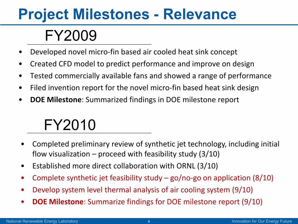
Project Milestones - Relevance
• Developed novel micro-fin based air cooled heat sink concept
• Created CFD model to predict performance and improve on design
• Tested commercially available fans and showed a range of performance
• Filed invention report for the novel micro-fin based heat sink design
• DOE Milestone: Summarized findings in DOE milestone report
FY2009
• Completed preliminary review of synthetic jet technology, including initial flow visualization – proceed with feasibility study (3/10)
• Established more direct collaboration with ORNL (3/10)
• Complete synthetic jet feasibility study – go/no-go on application (8/10)
• Develop system level thermal analysis of air cooling system (9/10)
• DOE Milestone: Summarize findings for DOE milestone report (9/10)
FY2010
National Renewable Energy Laboratory Innovation for Our Energy Future5
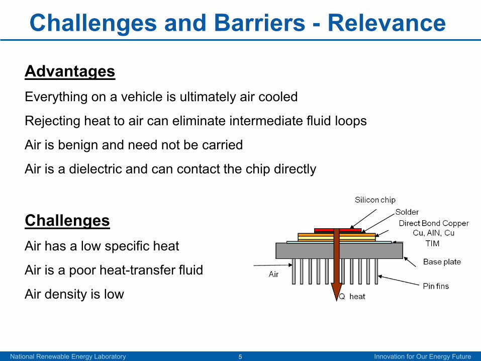
Challenges and Barriers - Relevance
AdvantagesEverything on a vehicle is ultimately air cooled
Rejecting heat to air can eliminate intermediate fluid loops
Air is benign and need not be carried
Air is a dielectric and can contact the chip directly
ChallengesAir has a low specific heat
Air is a poor heat-transfer fluid
Air density is low
National Renewable Energy Laboratory Innovation for Our Energy Future6
Examples of Automotive Air Cooling - Relevance
Honda Insight package
Power Rating 12 to 14 kWActive air cooling
Electric blower ~ 120 WHeat load ~ 700 W
AC PropulsionV2G model AC-150
Power Rating 150 kWActive air cooling
Electric blower ~ ??? WHeat load ~ 2000 W
• Electric Mini Cooper picture (right, 1st row): DOE Advanced Vehicle Testing Activity & Idaho National Laboratory• Honda power electronics pictures (left, 2nd row): Oak Ridge National Laboratory
National Renewable Energy Laboratory Innovation for Our Energy Future7
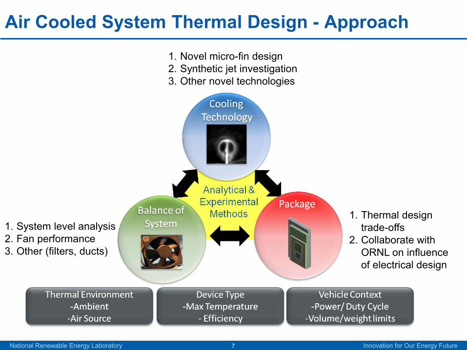
Air Cooled System Thermal Design - Approach
1. Novel micro-fin design2. Synthetic jet investigation3. Other novel technologies
1. System level analysis2. Fan performance3. Other (filters, ducts)
1. Thermal design trade-offs
2. Collaborate with ORNL on influence of electrical design
National Renewable Energy Laboratory Innovation for Our Energy Future8
Research and Development - Approach
1. Research novel cooling technology fundamental heat transfer
2. Scale cooling technology to inverter scale and investigate balance of system
3. Apply system design to inverter and find opportunities for improvement
4. Demonstrate prototype at vehicle level
National Renewable Energy Laboratory Innovation for Our Energy Future9
Thermal EnvironmentSource Temperature
Range (°C)Challenge/Opportunity
Under Hood 100 to 140 Not suitable for cooling devices at 125°C
External ambient air 30 to 45 Highly suitable for cooling
Cabin air 10 to 25 Limited advantage over ambient air. Penalty on air conditioners
Need to understand system trade-offs driven by air source local thermal environment which are influenced by inverter location
National Renewable Energy Laboratory Innovation for Our Energy Future10
Device Type and Vehicle Context
Improving device efficiency and maximum operating
temperature will increase air cooling system opportunity
Variability of air cooling system allows for control to load
conditions, maximizing “real world” system COP
National Renewable Energy Laboratory Innovation for Our Energy Future11
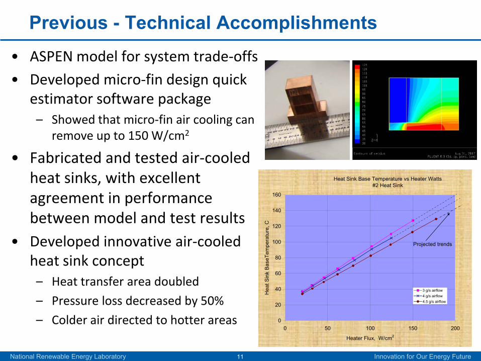
Previous - Technical Accomplishments• ASPEN model for system trade-offs
• Developed micro-fin design quick estimator software package
– Showed that micro-fin air cooling can remove up to 150 W/cm2
• Fabricated and tested air-cooled heat sinks, with excellent agreement in performance between model and test results
• Developed innovative air-cooled heat sink concept
– Heat transfer area doubled
– Pressure loss decreased by 50%
– Colder air directed to hotter areas
Heat Sink Base Temperature vs Heater Watts#2 Heat Sink
0
20
40
60
80
100
120
140
160
0 50 100 150 200
Heater Flux, W/cm2
Hea
t Sin
k B
aseT
empe
ratu
re, C
3 g/s airflow4 g/s airflow4.5 g/s airflow
Projected trends
National Renewable Energy Laboratory Innovation for Our Energy Future12
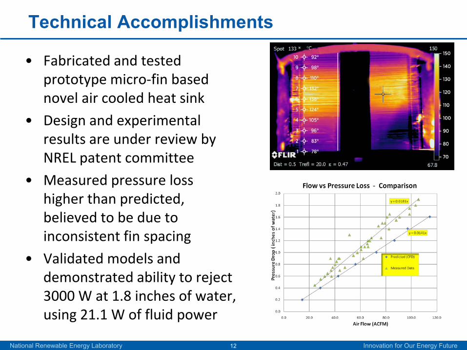
Technical Accomplishments
• Fabricated and tested prototype micro-fin based novel air cooled heat sink
• Design and experimental results are under review by NREL patent committee
• Measured pressure loss higher than predicted, believed to be due to inconsistent fin spacing
• Validated models and demonstrated ability to reject 3000 W at 1.8 inches of water, using 21.1 W of fluid power
National Renewable Energy Laboratory Innovation for Our Energy Future13
Technical Accomplishments
• Fully pulsatile jet
• Zero net mass flux : No external plumbing
• Imparts momentum : Influences medium
• Low electric power : Low cost
• Simple fabrication : High reliability
• Dominant vortical structures
Increase Momentum Transfer
Increase Surface Area
Heat Transfer Enhancement Strategy
1. Crook, A., Crowther, W.J., Wood, N.J. ‘A parametric study of a synthetic jet in a cross flow’, 22nd International Congress of Aeronautical Sciences, Harrogate, UK, 2000
1
National Renewable Energy Laboratory Innovation for Our Energy Future14
Technical Accomplishments
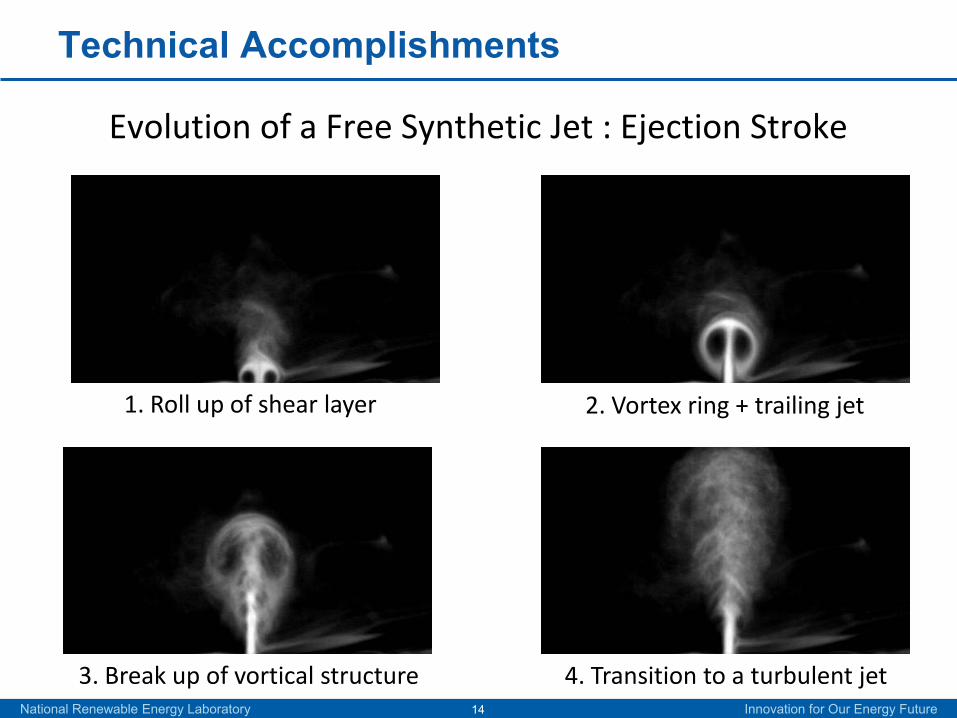
1. Roll up of shear layer 2. Vortex ring + trailing jet
3. Break up of vortical structure 4. Transition to a turbulent jet
Evolution of a Free Synthetic Jet : Ejection Stroke
National Renewable Energy Laboratory Innovation for Our Energy Future15
Technical Accomplishments
SJ Impingement on a Flat Surface
1. Roll up of shear layer 2. Evolution of free jet
3. Impingement 4. Secondary vortical structure
National Renewable Energy Laboratory Innovation for Our Energy Future16
Technical Accomplishments
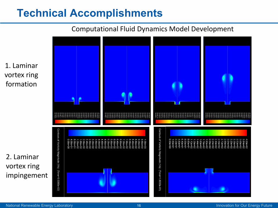
2. Laminar vortex ring impingement
Computational Fluid Dynamics Model Development
1. Laminar vortex ring formation
National Renewable Energy Laboratory Innovation for Our Energy Future17
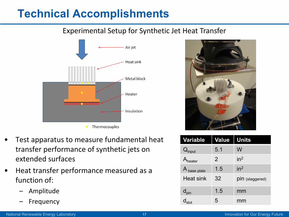
Technical AccomplishmentsExperimental Setup for Synthetic Jet Heat Transfer
• Test apparatus to measure fundamental heat transfer performance of synthetic jets on extended surfaces
• Heat transfer performance measured as a function of:
– Amplitude
– Frequency
Variable Value UnitsQinput 5.1 W
Aheater 2 in2
A base plate 1.5 in2
Heat sink 32 pin (staggered)
dpin 1.5 mm
dslot 5 mm
National Renewable Energy Laboratory Innovation for Our Energy Future18
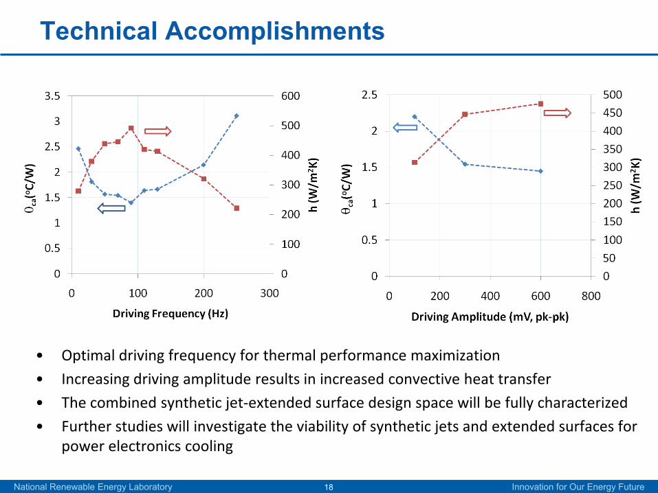
Technical Accomplishments
• Optimal driving frequency for thermal performance maximization
• Increasing driving amplitude results in increased convective heat transfer
• The combined synthetic jet-extended surface design space will be fully characterized
• Further studies will investigate the viability of synthetic jets and extended surfaces for power electronics cooling
National Renewable Energy Laboratory Innovation for Our Energy Future19
Technical AccomplishmentsA comparison of available fans, significant variation in performance
*Tested at NREL
National Renewable Energy Laboratory Innovation for Our Energy Future20
Technical Accomplishments
Single-stage fan/compressorpotential efficiencies
Source: Balje, Turbomachines, 1981
National Renewable Energy Laboratory Innovation for Our Energy Future21
Collaboration
• Oak Ridge National Laboratory– FY11:
• NREL will continue their system level air cooling thermal design including cooling technology, balance of system, and high level package thermal analysis
• ORNL will focus their work on wide-band gap materials in preparation for FY12 high temperature air cooled inverter design
– FY12: • NREL’s air cooling thermal system research will be used to provide useful air
cooling system thermal design information
• ORNL work to define the inverter electrical design and feasibility of inverter topologies
– FY13:• ORNL and NREL will collaborate to develop and demonstrate a viable high
temperature air cooled inverter
• Other interactions– FreedomCAR Electrical & Electronics Technical Team
– Delphi, PowerEx, Semikron, GE
National Renewable Energy Laboratory Innovation for Our Energy Future22
Future Work• FY10
– Complete synthetic jet feasibility study – go/no-go to system scale up
– Develop system level air cooling analysis approach, looking at interaction with packaging design
– Design and build single target air cooling test bench for fundamental heat transfer testing
– Investigate other novel air cooling approaches
• FY11– Design and build system level air cooling test bench
– use test bench to implement most promising technology on a multi-heat source array
– Microchannel design has been shown to perform near program heat transfer targets – work to reduce weight, volume, size, and apply to likely system topology
– Explore other novel air cooling technologies and surface enhancements
– Address balance of system questions, developing knowledge and solutions for fans, filters, and ducting
National Renewable Energy Laboratory Innovation for Our Energy Future23
Summary
• Overcome barriers to adoption of low-cost air-cooled heat sinks for power electronics; air remains the ultimate sink.
• Create system level understanding and designs addressing: advanced cooling technology, balance of system, and package thermal interactions; developing solutions from fundamental heat transfer, then system level design, to application - culminating in vehicle level viability demonstration with research partners.
DO
EM
issi
onSu
ppor
tA
ppro
ach
National Renewable Energy Laboratory Innovation for Our Energy Future24
Summary
• Fabricated and tested prototype novel micro-fin heat sink design
– Experimental validation of performance – showing 3kW heat rejection
– Design and results under review by NREL patent committee
• Conducted initial assessment of synthetic jets
• Showed range of fan performance through testing and research
• Collaborating with industry & partners– Established collaboration plan with ORNL to develop needed thermal
system knowledge for a FY12 high temperature inverter project
– Interacting with Auto OEMs and suppliers for test data, review, and validation activities including: Delphi, PowerEx, and Semikron
Tech
nica
lA
ccom
plis
hmen
tsC
olla
bora
tions
National Renewable Energy Laboratory Innovation for Our Energy Future25
Jason A. LustbaderSenior EngineerNational Renewable Energy [email protected]