485 Massachusetts Avenue, Suite 2 Cambridge, Massachusetts 02139 617.661.3248 | www.synapse‐energy.com Air Emissions Displacement by Energy Efficiency and Renewable Energy A Survey of Data, Methods, and Results June 26, 2015 AUTHORS Bruce Biewald Joseph Daniel Jeremy Fisher, PhD Patrick Luckow Alice Napoleon Nidhi Santen, PhD Kenji Takahashi
2. THEORY AND LITERATURE ................................................................................... 3
2.1. Introduction to Displaced Electricity Generation and Emissions ......................................... 3
2.2. Displaced Electricity and Emissions Explained .................................................................... 5
2.3. Selected Literature on Displaced Emissions from Energy Efficiency and Renewable Energy Resources ........................................................................................................................ 12
3. NATIONAL STUDIES ......................................................................................... 14
3.1. Annual Energy Outlook 2014 ........................................................................................... 15
3.2. Synapse Clean Energy Future Scenarios ........................................................................... 18
6.2. The AVoided Emissions and geneRation Tool (AVERT) ..................................................... 34
6.3. Case Study 1: CO2 Emissions Displacement Potentials from Energy Efficiency and Renewable Energy Resources in 10 U.S. Regions .............................................................. 35
6.4. Case Study 2: CO2 Emissions Displaced from New Energy Efficiency in 2012 Across the United States ................................................................................................................... 38
APPENDIX A: EXPANDED METHODS AND LITERATURE REVIEW ......................................... A1
ACKNOWLEDGEMENT
This report was prepared by Synapse Energy Economics (Synapse), pursuant to a grant from the Energy
Foundation, to assess the greenhouse gas emissions impacts of introducing new energy efficiency and
renewable energy resources into U.S. power systems.
Synapse Energy Economics, Inc. Emissions Displacement by Energy Efficiency and Renewable Energy 1
1. EXECUTIVE SUMMARY
Energy efficiency and renewable energy can, and do, reduce air pollution that would otherwise be
emitted from power plants on the electricity grid. Although the grid operates as a large integrated
network—with hundreds of individual generating units dispatched to meet constantly changing
customer demand on a continuous (second‐to‐second) basis—it is possible to understand and estimate
the impacts of energy efficiency and renewable energy on grid operations. Typically, energy efficiency
and renewable energy displace operations from a mix of generating stations that burn coal, natural gas,
and occasionally oil to generate electric power. “Displacement” occurs when a new energy efficiency or
renewable energy resource eliminates or reduces the need for megawatt‐hours (MWh) of electricity
generation from fossil‐fired power stations. Over a longer period of time, new energy efficiency or
renewable energy resources can also defer or altogether avoid the addition of fossil generating units
that would otherwise have been built, or expedite the retirement of the least efficient, highest emitting
generation resources. By reducing operations, avoiding capacity, or expediting retirements of fossil
power stations, additions in energy efficiency and renewable energy resources result in decreased air
emissions of carbon dioxide (CO2), sulfur dioxide (SO2), oxides of nitrogen (NOX), particulate matter, and
toxics.
In this report, Synapse looks at four types of studies to examine the impact of energy efficiency and
renewable energy on stationary‐source emissions, and to quantify the resulting decreases in CO2
emissions. The studies include analyses at the national, regional, and utility service territory levels,
conducted by a variety of authors: a federal agency, grid operators, utilities, and a private consulting
firm. For the most part, these studies were not designed to specifically examine the emissions impact of
energy efficiency or renewable energy, and yet they consistently show that increases in energy
efficiency or renewable energy displace CO2‐emitting generation.
The national‐level studies examined here contain scenarios with more energy efficiency and/or
renewable energy than would be expected in a reference or business‐as‐usual case, allowing us to
compare emissions as a function of efficiency and renewable energy. For example, the Energy
Information Agency’s (EIA’s) Annual Energy Outlook (AEO) includes scenarios that differ based on simple
policy mechanisms and inputs. This allows for greater isolation of impacts relative to models of other,
more complex policy scenarios such as implementation of a carbon tax. Analysis of the 2014 AEO reveals
that additional energy efficiency and renewable energy resources are projected to displace emissions at
a rate of between 0.75 – 0.35 metric tons per megawatt hour (tCO2/MWh) (in this report, called a
displaced emissions rate), depending on the extent of the energy displacement and the year in which it
is projected to occur. In a forthcoming study, Synapse Energy Economics uses the National Renewable
Energy Laboratory’s ReEDS model and public data sources to investigate how the U.S. electric power
system would respond to a “Clean Energy Future” case. This analysis projects that, as reliance on fossil
fuels declines in the Clean Energy Future case relative to a Reference case, emissions decline
Synapse Energy Economics, Inc. Emissions Displacement by Energy Efficiency and Renewable Energy 2
substantially, amounting to a displaced emission rate of about 0.8 tCO2/MWh throughout the study
period.
The seven regional transmission organizations (RTOs), responsible for dispatching electricity over large
areas of the United States, provide another source of data on displacement of emissions. The findings of
four recently published RTO reports indicate that regional emissions displacement rates over the past
year have ranged from 0.80 – 0.30 tCO2/MWh. These numbers are considerable. To put it in context, a
500 megawatt wind farm might displace 500,000 to 1.2 million tCO2 every year,1 or up to 25 million tCO2
over a 20‐year life.
Many utilities assemble forward‐looking long‐term resource plans that analyze potential future resource
scenarios. Some utilities evaluate alternative, clean energy portfolios with more aggressive renewable
energy and/or energy efficiency resources. The results of these analyses reveal the extent to which such
clean energy scenarios can result in additional reductions in CO2 emissions. Based on a review of dozens
of these long‐term integrated resource plans (IRPs), Synapse identified three studies—by Tennessee
Valley Authority, PacifiCorp, and Duke Energy Carolinas—that provide both the annual changes in
energy mix and CO2 emissions for one or more clean energy portfolios relative to a reference case
portfolio. For each IRP reviewed, projected electric system CO2 emissions were lower for portfolios with
increased energy efficiency or renewable energy penetration than for a reference case portfolio with
less energy efficiency or renewable energy. For example, TVA’s Maximize Renewables plan reduces CO2
emissions by 7 million tCO2 by 2033 relative to its Reference Plan.
Lastly, the report presents the results from the U.S. Environmental Protection Agency’s (EPA’s) AVERT
model, which illustrate the pronounced effects that energy efficiency and renewable energy can have on
operations and emissions of fossil‐based generators. The larger the proportion of higher carbon‐
emitting resources in a region’s existing generation capacity mix, the larger the role energy efficiency
and renewable energy can play in displacing CO2 emissions. Additionally, the more these zero‐emitting
resources are implemented in a region, the larger is the volume of CO2 emissions displaced as a
percentage of total fossil generating unit CO2 emissions. Results of this analysis show that historical CO2
emissions displaced from new energy efficiency in 2012 ranged from roughly 4.9 million tCO2 in the
Great Lakes/Mid‐Atlantic region, to a low of 0.2 million tCO2 in the Lower Midwest region, a pattern
reflective of the penetration of new efficiency initiatives and policies.
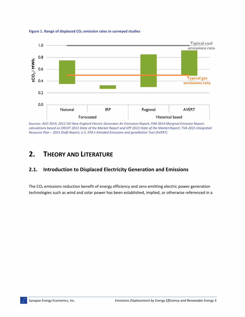
Figure 1 summarizes results from the sets of studies reviewed. The displaced emissions rates of the
studies were largely bounded by the U.S. electric system‐wide average emissions rate for natural gas‐
fired power plants (all types) on the one hand, and by the average emissions rate for coal‐fired power
plants on the other. It also displays the typical emissions rate of coal and natural gas‐fired units.2
1 500 MW windfarm at 35% assumed capacity factor and 0.3t/MWh displacement = 460,000 tons CO2. At 0.8 t/MWh =
1,230,000 tons CO2.
2 U.S. EPA. Clean Energy. Available at: http://www.epa.gov/cleanenergy/energy‐and‐you/affect/air‐emissions.html.
Synapse Energy Economics, Inc. Emissions Displacement by Energy Efficiency and Renewable Energy 3
Figure 1. Range of displaced CO2 emission rates in surveyed studies
Sources: AEO 2014; 2012 ISO New England Electric Generator Air Emissions Report; PJM 2014 Marginal Emission Report; calculations based on ERCOT 2013 State of the Market Report and SPP 2013 State of the Market Report; TVA 2015 Integrated Resource Plan – 2015 Draft Report; U.S. EPA’s AVoided Emissions and geneRation Tool (AVERT).
2. THEORY AND LITERATURE
2.1. Introduction to Displaced Electricity Generation and Emissions
The CO2 emissions reduction benefit of energy efficiency and zero‐emitting electric power generation
technologies such as wind and solar power has been established, implied, or otherwise referenced in a
Synapse Energy Economics, Inc. Emissions Displacement by Energy Efficiency and Renewable Energy 4
wide range of popular energy sector reports for over a decade.3,4,5,6,7,8,9,10 The National Action Plan for
Energy Efficiency (2009) stated a goal of 500 million metric tons11 of CO2 reductions from energy
efficiency by 2025 in the United States. EPA’s Roadmap for Incorporating Energy Efficiency/Renewable
Energy Policies and Programs into State and Tribal Implementation Plans (2012) provides guidance for
including energy efficiency and renewable energy emission benefits in local air quality plans. McKinsey &
Company’s Greenhouse Gas Abatement Cost Curve (2009) finds that relatively low cost energy efficiency
technologies have the potential to reduce CO2 equivalent emissions globally by 14 billion tons. Among
many other examples, EIA’s AEO (2014) shows different scenarios, all of which include energy efficiency‐
based CO2 reductions in forecasted energy use and emissions. (The AEO scenarios are discussed further
in Chapter 3.)
Underlying all of these references is the idea that energy efficiency and renewable energy resources can
displace emissions that would otherwise have been released from carbon‐emitting generation
resources. However, while energy efficiency and renewable energy have the potential to reduce
emissions by avoiding electricity generation from carbon‐emitting resources, the reductions are
indirect12 and therefore can be difficult to characterize. The temporal and spatial variation in demand
reduction from different energy efficiency and renewable energy resources, and the complexity with
3 U.S. Energy Information Administration. 2014. Annual Energy Outlook 2014, with projections to 2040. Report DOE/EIA‐0383.
Available at: http://www.eia.gov/forecasts/archive/aeo14/pdf/0383(2014).pdf.
4 U.S. EPA. 2012. Roadmap for Incorporating Energy Efficiency/Renewable Energy Policies and Programs into State and Tribal
Implementation Plans. Available at: http://epa.gov/airquality/eere/pdfs/eeremanual.pdf.
5 Electric Power Research Institute. 2007. The Power to Reduce CO2 Emissions: The Full Portfolio. Discussion paper prepared for
the EPRI 2007 Summer Seminar by the EPRI Energy Technology Assessment Center. Available at: http://mydocs.epri.com/docs/public/DiscussionPaper2007.pdf.
6 McKinsey & Company. 2009. Pathways to a Low Carbon Economy. Version 2 of the Global Greenhouse Gas Abatement Cost
Curve. Available at: http://www.mckinsey.com/~/media/McKinsey/dotcom/client_service/Sustainability/cost%20curve%20PDFs/Pathways_lowcarbon_economy_Version2.ashx.
7 International Panel on Climate Change. 2014. Climate Change 2014: Mitigation of Climate Change. Contribution of Working
Group III to the Fifth Assessment Report of the Intergovernmental Panel on Climate Change [Edenhofer, O., R. Pichs‐Madruga, Y. Sokona, E. Farahani, S. Kadner, K. Seyboth, A. Adler, I. Baum, S. Brunner, P. Eickemeier, B. Kriemann, J. Savolainen, S. Schlömer, C. von Stechow, T. Zwickel and J.C. Minx (eds.)]. Cambridge, United Kingdom and New York, NY: Cambridge University Press. Available at: http://mitigation2014.org/report/publication/.
8 Pacala, S. and R. Socolow. 2004. “Stabilization Wedges: Solving the Climate Problem for the Next 50 Years with Current
Technologies.” Science 305: 968‐972.
9 Prindle, W. 2009. “Energy Efficiency as a Low‐Cost Resource for Achieving Carbon Emissions Reductions.” National Action Plan
for Energy Efficiency. Prepared by ICF International, Inc. Available at: www.epa.gov/eeactionplan.
10 National Research Council. 2010. Real Prospects for Energy Efficiency in the United States. Washington, DC: The National
Academies Press.
11 Throughout this report, tons refer to metric tons. Where original sources cite short tons, these values were converted to
metric tons for consistency.
12 Energy efficiency and renewable energy emission reductions are indirect in that they are not the result of direct controls on
electric generating unit stacks; rather, they are the result of system‐level changes that call on the power plants to reduce their output.
Synapse Energy Economics, Inc. Emissions Displacement by Energy Efficiency and Renewable Energy 5
which energy efficiency and renewable energy resources interact with the physical generation portfolio
and other characteristics of the underlying electricity markets can make the process by which emissions
are avoided rather opaque. In short, determining the electric generation units (EGUs) from which
production and emissions are displaced—and how—is complex.
2.2. Displaced Electricity and Emissions Explained
In the electric power sector, each unit of energy saved by a new energy efficiency program or supplied
by a new renewable energy resource avoids the need for energy from an existing generator. In most
cases, the generating resources most readily avoided are fossil‐fired, affecting CO2 emissions that would
have otherwise been released. Breaking down the mechanism of displacement can be a useful way to
consider how energy efficiency and renewable energy resources reduce overall emissions. We can think
of the effect of any specific project upon the electricity grid in terms of its effect on how units are
actually dispatched (the “operating margin”) and its effect on longer‐term capacity additions (the “build
margin”).
First, a new energy efficiency and renewable energy resource can displace emissions by eliminating or
reducing the need for megawatt‐hours (MWh) of electricity generation at an existing carbon‐emitting
EGU—displacing electricity at the operating margin. Consider a new energy efficiency program. When a
new energy efficiency resource actively begins reducing the demand for electricity, the system responds
by reducing the level of generation at the EGUs “on the margin”—the set of generating units that were
operating precisely to meet those last units of energy that otherwise would be demanded. Typically,
operating margin impacts occur in the near term13 with respect to a new energy efficiency and
renewable energy resource coming online, but this is not necessarily the case.
For CO2 emissions to be displaced, the EGUs that are displaced must be carbon‐emitting resources.
Indeed, in the U.S. power sector and in many power sectors around the world, this is the case. EGUs are
dispatched on a cost merit‐order basis: the least expensive units (reflecting their fuel costs, start‐up and
shut‐down costs, and other variable operations and maintenance costs) and the least flexible units
(reflecting their ramp rates and minimum capacity requirements) are called upon to generate power
first as “base load” resources, and successively more expensive units are called upon to meet the next
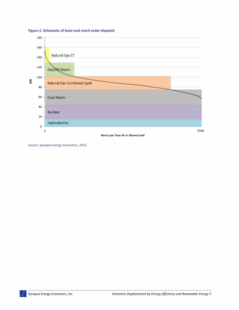
increments of demand up to the peak load. This merit‐order process results in nuclear power and run‐
of‐the‐river hydropower most often serving as base load resources, followed by coal, natural gas, and
oil‐fired resources filling in each successive increment of required load.
Figure 2 provides a schematic of the typical merit order of dispatchable resources.
13 In this context, near term means as short as seconds to as long as roughly three years (corresponding to the shortest period
in which a new peaking resource could be brought online).
Synapse Energy Economics, Inc. Emissions Displacement by Energy Efficiency and Renewable Energy 6
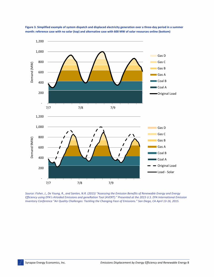
Figure 3 illustrates the effect of renewable solar resources displacing generation from marginal fossil
EGUs. When electricity demand is reduced due to energy efficiency, generation resources can be
thought of as being displaced in a reverse merit‐order, with dispatchable oil, natural gas, and coal‐fired
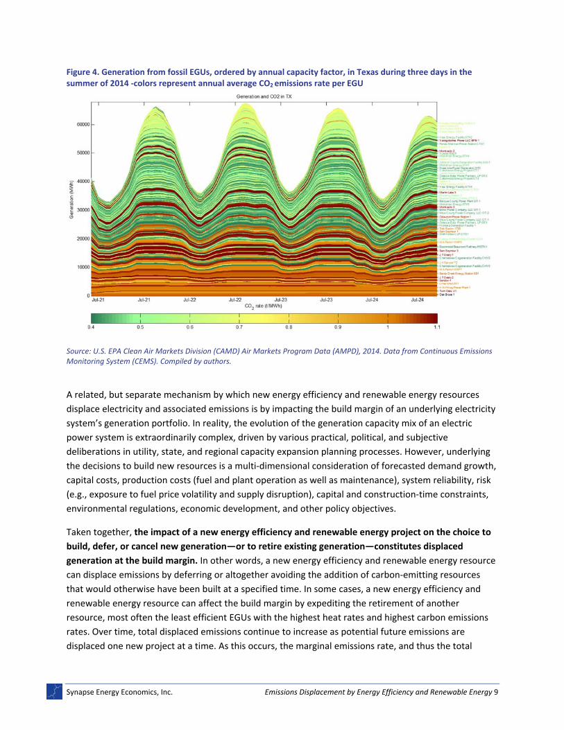
resources being called on first to turn off or down. This process is further depicted in Figure 4, which
shows actual generation from fossil EGUs in the Texas system during three days in the summer of 2014.
Generation is ordered by annual capacity factors of the corresponding EGUs—showing an effective
“dispatch” order—and highlights the opportunity for higher‐emitting units to be displaced during
marginal and peak load times. In the case of a new renewable energy resource, such as a new wind farm
or a solar PV installation, the displacement end‐effect is the same, albeit through a slightly different
physical mechanism. In the case of increased wind generation, for example, overall electricity demand is
not reduced; the renewable power is being used to meet existing load. However, due to the low variable
costs incurred by renewable energy resources such as wind and solar (with no fuel costs and negligible
other operations and maintenance costs), their merit order with respect to other resources is high; the
least‐cost dispatch decision thus most often involves using renewable generation whenever it is
available.14 This approach results in dispatchable EGUs participating in the typical merit order process
experiencing lower “net demand”; natural gas‐ and coal‐fired generators still experience a displacement
effect from renewable energy. Overall, new energy efficiency and renewable energy resources displace
emissions from EGUs at the operating margin because the MWhs avoided (from energy efficiency) or
produced (from renewable energy) reduce or eliminate, respectively, the need for MWh production at
existing fossil‐fired EGUs during the same time periods.
14 Exceptions to this include times of congestion or other physical reliability or unique market constraints that can require the
system operator to “curtail” renewable power.
Synapse Energy Economics, Inc. Emissions Displacement by Energy Efficiency and Renewable Energy 7
Figure 2. Schematic of least‐cost merit order dispatch
Source: Synapse Energy Economics. 2015.
Synapse Energy Economics, Inc. Emissions Displacement by Energy Efficiency and Renewable Energy 8
Figure 3. Simplified example of system dispatch and displaced electricity generation over a three‐day period in a summer
month: reference case with no solar (top) and alternative case with 600 MW of solar resources online (bottom)
Source: Fisher, J., De Young, R., and Santen, N.R. (2015) “Assessing the Emission Benefits of Renewable Energy and Energy Efficiency using EPA’s AVoided Emissions and geneRation Tool (AVERT).” Presented at the 2015 U.S. EPA International Emission Inventory Conference "Air Quality Challenges: Tackling the Changing Face of Emissions.” San Diego, CA April 13‐16, 2015.
‐
200
400
600
800
1,000
1,200
7/7 7/8 7/9
Dem
and (MW)
Gas D
Gas C
Gas B
Gas A
Coal B
Coal A
Original Load
‐
200
400
600
800
1,000
1,200
7/7 7/8 7/9
Dem
and 9MW)
Gas D
Gas C
Gas B
Gas A
Coal B
Coal A
Original Load
Load ‐ Solar
Synapse Energy Economics, Inc. Emissions Displacement by Energy Efficiency and Renewable Energy 9
Figure 4. Generation from fossil EGUs, ordered by annual capacity factor, in Texas during three days in the summer of 2014 ‐colors represent annual average CO2 emissions rate per EGU
Source: U.S. EPA Clean Air Markets Division (CAMD) Air Markets Program Data (AMPD), 2014. Data from Continuous Emissions Monitoring System (CEMS). Compiled by authors.
A related, but separate mechanism by which new energy efficiency and renewable energy resources
displace electricity and associated emissions is by impacting the build margin of an underlying electricity
system’s generation portfolio. In reality, the evolution of the generation capacity mix of an electric
power system is extraordinarily complex, driven by various practical, political, and subjective
deliberations in utility, state, and regional capacity expansion planning processes. However, underlying
the decisions to build new resources is a multi‐dimensional consideration of forecasted demand growth,
capital costs, production costs (fuel and plant operation as well as maintenance), system reliability, risk
(e.g., exposure to fuel price volatility and supply disruption), capital and construction‐time constraints,
environmental regulations, economic development, and other policy objectives.
Taken together, the impact of a new energy efficiency and renewable energy project on the choice to
build, defer, or cancel new generation—or to retire existing generation—constitutes displaced
generation at the build margin. In other words, a new energy efficiency and renewable energy resource
can displace emissions by deferring or altogether avoiding the addition of carbon‐emitting resources
that would otherwise have been built at a specified time. In some cases, a new energy efficiency and
renewable energy resource can affect the build margin by expediting the retirement of another
resource, most often the least efficient EGUs with the highest heat rates and highest carbon emissions
rates. Over time, total displaced emissions continue to increase as potential future emissions are
displaced one new project at a time. As this occurs, the marginal emissions rate, and thus the total
Synapse Energy Economics, Inc. Emissions Displacement by Energy Efficiency and Renewable Energy 10
amount of annual emissions displaced by energy efficiency and renewable energy, tends to decrease as
newer, higher‐efficiency and lower‐emitting resources are deferred at the build margin and appear
more frequently at the operating margin.
Return for a moment to the example of the new energy efficiency resource discussed above in the
context of operating margins. The energy efficiency resource will reduce overall demand, which will
subsequently be factored into forecasted demand growth. New generation capacity additions tend to
track peak demand; a reduction in this demand will generally reduce the total MW required in future
years to continue reliably meeting customer requirements. Fossil‐based electricity and the emissions
associated with them will be displaced to the extent that they were planned to meet peak loads (i.e.,
natural gas‐fired combustion turbines are the most commonly planned peaking EGUs). It is worth noting
that displacement by way of the build margin tends to occur over longer timeframes than displacement
at the operating margin; decisions to add new capacity typically happen in two to five year planning
cycles and there are also multi‐year lead times for constructing new EGUs. However, this does not need
to be the case. Consider an example where a group of energy efficiency and renewable energy projects
totaling 50 MW comes online immediately preceding construction of a phased‐unit fossil‐fired power
plant with four identical 50 MW natural gas units with short construction times. From a system planning
perspective, the energy efficiency and renewable energy can defer or even eliminate installation of one
of these units altogether.
Various factors will affect the level of displacement at either the operating or build margin, including the
size of the new energy efficiency and renewable energy resource, its timing for being online, and
operating characteristics. Additionally, there are a range of features of the underlying electricity grid
that factor into the relative effect of a new energy efficiency and renewable energy resource on
operating versus build‐margin displacements, including system management, transmission constraints,
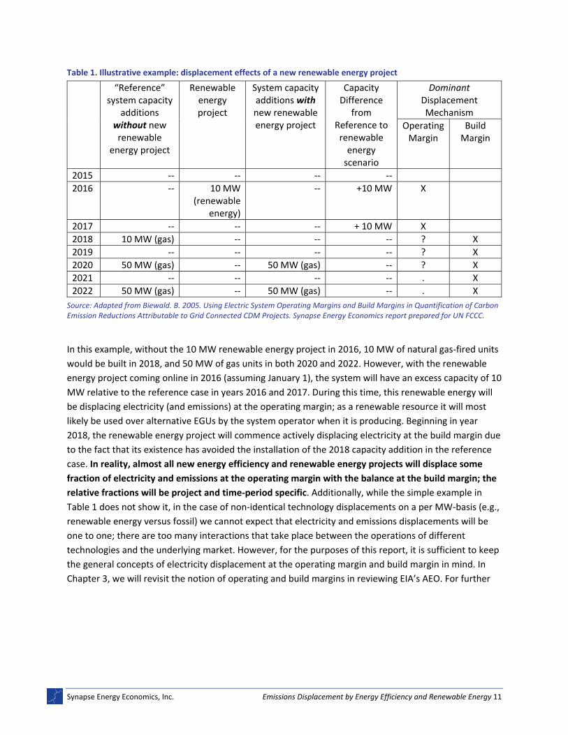
capacity surpluses or shortages, and of course the underlying physical generation capacity mix. Table 1
uses a simple example to show how a new energy efficiency and renewable energy resource can
displace electricity (and thus emissions) at the operating and build margins.
Synapse Energy Economics, Inc. Emissions Displacement by Energy Efficiency and Renewable Energy 11
Table 1. Illustrative example: displacement effects of a new renewable energy project
“Reference” system capacity
additions without new renewable
energy project
Renewable energy project
System capacity additions with new renewable energy project
Capacity Difference
from Reference to renewable energy scenario
Dominant Displacement Mechanism
Operating Margin
Build Margin
2015 ‐‐ ‐‐ ‐‐ ‐‐
2016 ‐‐ 10 MW (renewable
energy)
‐‐ +10 MW X
2017 ‐‐ ‐‐ ‐‐ + 10 MW X
2018 10 MW (gas) ‐‐ ‐‐ ‐‐ ? X
2019 ‐‐ ‐‐ ‐‐ ‐‐ ? X
2020 50 MW (gas) ‐‐ 50 MW (gas) ‐‐ ? X
2021 ‐‐ ‐‐ ‐‐ ‐‐ . X
2022 50 MW (gas) ‐‐ 50 MW (gas) ‐‐ . X
Source: Adapted from Biewald. B. 2005. Using Electric System Operating Margins and Build Margins in Quantification of Carbon Emission Reductions Attributable to Grid Connected CDM Projects. Synapse Energy Economics report prepared for UN FCCC.
In this example, without the 10 MW renewable energy project in 2016, 10 MW of natural gas‐fired units
would be built in 2018, and 50 MW of gas units in both 2020 and 2022. However, with the renewable
energy project coming online in 2016 (assuming January 1), the system will have an excess capacity of 10
MW relative to the reference case in years 2016 and 2017. During this time, this renewable energy will
be displacing electricity (and emissions) at the operating margin; as a renewable resource it will most
likely be used over alternative EGUs by the system operator when it is producing. Beginning in year
2018, the renewable energy project will commence actively displacing electricity at the build margin due
to the fact that its existence has avoided the installation of the 2018 capacity addition in the reference
case. In reality, almost all new energy efficiency and renewable energy projects will displace some
fraction of electricity and emissions at the operating margin with the balance at the build margin; the
relative fractions will be project and time‐period specific. Additionally, while the simple example in
Table 1 does not show it, in the case of non‐identical technology displacements on a per MW‐basis (e.g.,
renewable energy versus fossil) we cannot expect that electricity and emissions displacements will be
one to one; there are too many interactions that take place between the operations of different
technologies and the underlying market. However, for the purposes of this report, it is sufficient to keep
the general concepts of electricity displacement at the operating margin and build margin in mind. In
Chapter 3, we will revisit the notion of operating and build margins in reviewing EIA’s AEO. For further
Synapse Energy Economics, Inc. Emissions Displacement by Energy Efficiency and Renewable Energy 12
discussion of operating and build margins, and the theory of electricity displacement, see Biewald
(2005)15 and Matsuo (2004).16
2.3. Selected Literature on Displaced Emissions from Energy Efficiency and Renewable Energy Resources
Responding to the complexity with which new energy efficiency and renewable energy resources can
affect CO2 emissions, and a need to continue supporting various policy and planning objectives,
numerous academic studies over the past decade have sought to estimate the electricity generation
displaced by energy efficiency or renewable energy (and the subsequent displaced
15 Biewald, B. 2005. Using Electric System Operating Margins and Build Margins in Quantification of Carbon Emission
Reductions Attributable to Grid Connected CDM Projects. Synapse Energy Economics report prepared for UN FCCC.
16 Matsuo. 2004. CDM Methodologies Guidebook. Japan: Ministry of the Environment (MOE), Global Environment Centre
Foundation (GEC), Climate Experts Ltd. Available at: http://gec.jp/main.nsf/en/Publications‐Others‐CDM_Meth_Guidebook.
Synapse Energy Economics, Inc. Emissions Displacement by Energy Efficiency and Renewable Energy 13
emissions).17,18,19,20,21,22,23,24,25,26,27,28,29,30,31,32 Most of these studies integrate various features that are
known, or can be observed, about the underlying electricity system into quantitative models that
provide the amount of electricity and emissions displaced for given levels of renewable energy and
energy efficiency on the system. Methods for evaluation vary, but the majority focus on displacement at
the operating margin. On one end of this spectrum are simple statistical methods that involve
calculating an average emission rate across all operating EGUs in a region using historical data, to apply
as the rate by which emissions are reduced in the future. On the other end are very complex simulation
17 Bettle, R., Pout, C.H., and E.R. Hitchin. 2000. “Interactions Between Electricity‐Saving Measures and Carbon Emissions from
Power Generation in England and Wales.” Energy Policy: 34: 3434‐3446.
18 Cullen, J. 2013. “Measuring the Environmental Benefits of Wind‐Generated Electricity.” American Economic Journal:
Economic Policy. 5(4): 107‐133.
19 Kaffine, D.T., McBee, B.J., and J. Lieskovsky. 2013. “Emission Savings from Wind Power Generation in Texas.” The Energy
Journal 34(1): 155‐175.
20 Siler‐Evans, K., I.L. Azevedo, M.G. Morgan, and J. Apt. 2013. “Regional Variations in the Health, Environmental, and Climate
Benefits of Wind and Solar Generation.” Proceedings of the National Academy of Sciences 110(29): 11768‐11773.
21 Hausman, E., Fisher, J., and B. Biewald. 2008. “Analysis of indirect emissions benefits of wind, landfill gas, and municipal solid
waste generation.” EPA Document 600/R‐08‐087, Prepared for the US Environmental Protection Agency by Synapse energy Economics, Inc.
22 High, C. and G. Neeraj. 2011. Avoided Emissions from the Antrim Wind Project. Accessed April 2015 at http://antrim‐
23 Newcomer, A., S.A. Blumsack, J. Apt, L.B. Lave, and M.G. Morgan. 2008. “Short Run Effects of a Price on Carbon Dioxide
Emissions from U.S. Electric Generators.” Environmental Science and Technology 42(9): 3139–44.
24 Rothschild, S. and A. Diem. 2009. “Total, Non‐base load, eGRID Subregion, State? Guidance on the Use of eGRID Output
Emission Rates.” 18th Annual International Emission Inventory Conference "Comprehensive Inventories ‐Leveraging Technology and Resources". Baltimore, MD.
25 Zhai, P. and P. Larsen, D. Millstein, S. Menon, and E. Masanet. 2012. “The Potential for Avoided Emissions from Photovoltaic
Electricity in the United States.” Energy 47: 443‐450.
26 Denny, E. and M. O'Malley, M. 2006. "Wind generation, power system operation, and emissions reduction," Power Systems,
IEEE Transactions on 21(1): pp.341,347. doi: 10.1109/TPWRS.2005.857845
27 Denny, E. and M. O’Malley. 2007. “Quantifying the Total Net Benefits of Grid Integrated Wind.” Power Systems, IEEE
Transactions on 22(2).
28 Denholm, P., R.M. Margolis, and J.M. Milford. 2009. “Quantifying Avoided Fuel Use and Emissions from Solar Photovoltaic
Generation in the Western United States.” Environmental Science and Technology 43(1): 226‐232.
29 Fisher, J. et al. 2009. “Emissions Reductions from Energy Efficiency and Renewable Energy in California Air Quality
Management Districts.” California Energy Commission Report CEC‐500‐2013‐047. Prepared for the California Energy Commission by Synapse Energy Economics.
30 Valentino, L., V. Valenzuela, A. Botterud, Z. Zhou, and G. Conzelmann. 2012. “System‐Wide Emissions Implications of
Increased Wind Power Penetration.” Environmental Science and Technology 46: 4200‐4206.
31 National Renewable Energy Laboratory (NREL). 2013. The Western Wind and Solar Integration Study Phase 2. Available at:
http://www.nrel.gov/docs/fy13osti/55588.pdf.
32 Sustainable Energy Authority of Ireland (SEAI). 2012. “Quantifying Ireland’s Fuel and CO2 Emissions Savings from Renewable
Electricity in 2012” Available at: http://www.seai.ie/Publications/Statistics_Publications/Energy_Modelling_Group_Publications/Quantifying‐Ireland%E2%80%99s‐Fuel‐and‐CO2‐Emissions‐Savings‐from‐Renewable‐Electricity‐in‐2012.pdf.
Synapse Energy Economics, Inc. Emissions Displacement by Energy Efficiency and Renewable Energy 14
or optimization electricity dispatch models that represent detailed features of the underlying physical
electrical system, costs, and operational constraints of individual generators, transmission, and aspects
of how the regional market is organized and run.
Within these categories, models differ with respect to the level of detail, the assumptions they rest
upon, and the level of accessibility for decision‐makers and other key stakeholders. There are inherent
tradeoffs and differences between these two approaches, and because of this the reality is that most
methods used to estimate displaced emissions in the electricity sector fall somewhere in between the
simple and complex. As an example, AVERT (the AVoided Emissions and geneRation Tool) is a statistical
model of intermediate complexity, but it is still able to capture a high degree of electricity‐system level
accuracy and provide valuable insight about displaced emissions. (AVERT will be described further in
Chapter 6.) Despite the variation in methods and level of detail included in the studies, several key
themes emerge across their results:
Displacement increases with the scale of net demand reduction from energy efficiency and renewable energy
The underlying generation capacity portfolio of a region is a strong driver of displacement potential from resources such as renewable energy and energy efficiency
Increased renewable energy may increase some short‐term emissions due to cycling (i.e. running existing units at a lower efficiency), but overall substantially reduces emissions by displacing fossil‐fired EGUs
Coal‐fired EGUs were more impacted than might be expected based on traditional indicators of “marginal” units
Further details for many of the studies cited above are provided in Appendix A.
3. NATIONAL STUDIES
Estimates of displaced emissions can be calculated from a number of national level studies.33 Many of
these studies look at a range of different scenarios that include more energy efficiency and/or
renewable energy than would be expected in a reference case or “business‐as‐usual” case. Many studies
change multiple variables; consequently, it is difficult to attribute reductions in emissions to a specific
feature of that scenario. Some studies do model single‐variable changes to inputs as compared to a
reference case. This would include reducing the price of energy efficiency or renewable energy,34 or
33 See Section 2.3 of this report.
34 Additional energy efficiency is likely to impact renewable energy because it can reduce Renewable Portfolio Standard
requirements and defer the need to build new resources.
Synapse Energy Economics, Inc. Emissions Displacement by Energy Efficiency and Renewable Energy 15
imposing a cost or cap on emissions from fossil fuel‐fired generating units. The EIA’s AEO includes
scenarios that differ based on simple policy mechanisms and inputs, allowing for greater isolation of
impacts relative to models of other, more complex policy scenarios like implementation of a carbon
tax.35 In a study to be published later this summer, Synapse is investigating how the electric power
system would respond to an aggressive Renewable Portfolio Standard and incremental energy efficiency
savings targets of 2 percent per year.
This chapter looks at the most recent complete EIA AEO model runs and the forthcoming Synapse study
to calculate displaced emissions rates as a result of increased energy efficiency or renewable energy.
3.1. Annual Energy Outlook 2014
Each year, the EIA publishes the AEO report, presenting a number of long‐term projections of U.S.
energy supply, demand, and prices. AEO is often relied upon for this type of information because it is
produced by an independent agency, updated regularly, and is publically available. The report includes a
reference case that reflects baseline assumptions and a series of alternative scenarios. For the 2014 AEO
report (AEO 2014), the EIA ran 30 alternative scenarios, including several with increased amounts of
energy efficiency and/or renewable energy.36
This chapter compares the results of the three alternative scenarios to EIA’s reference case: Low
Renewable Cost, High Demand Technology, and Best Available Demand Technology. Each of the three
alternative cases differs only slightly from the reference case, allowing us to infer the incremental
impact of additional energy efficiency and/or renewable energy. The alternative scenarios are described
below.37
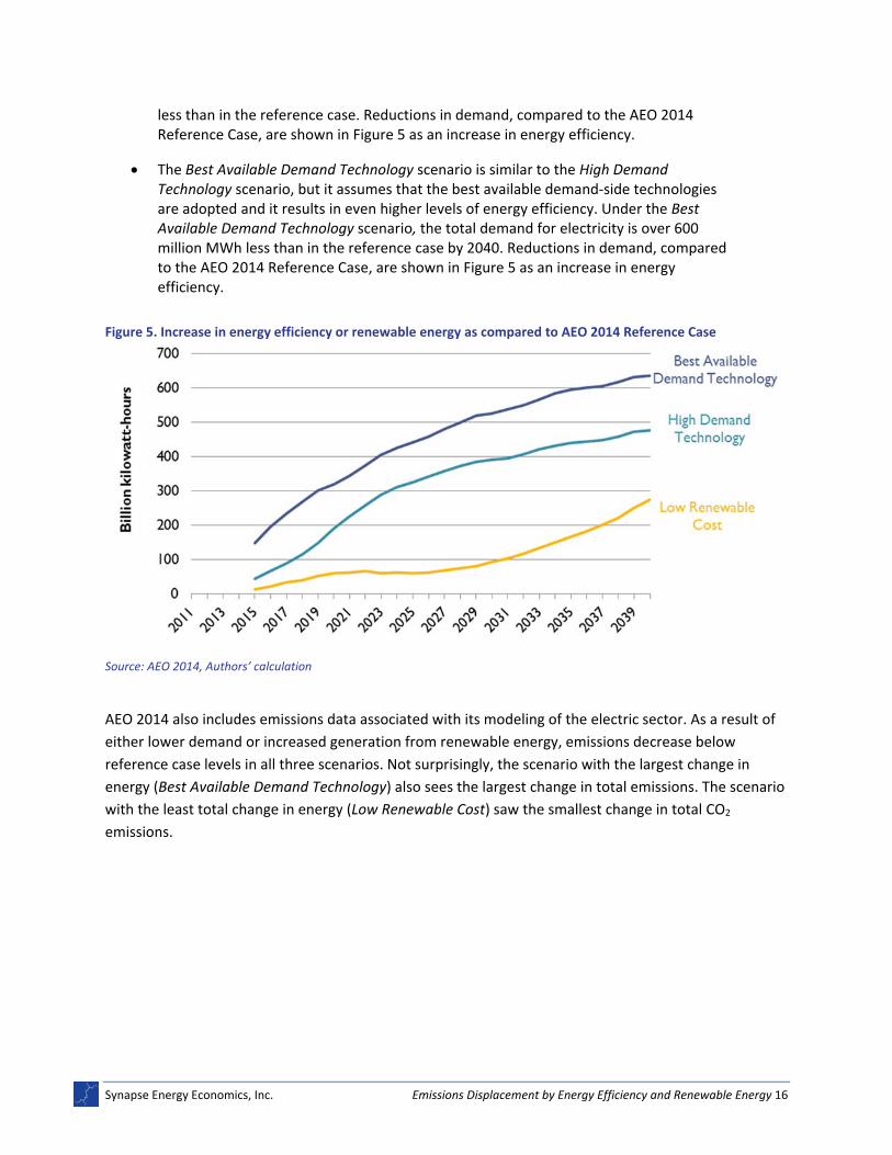
As the name implies, the Low Renewable Cost scenario assumes the costs of new renewable energy resources are lower than in the reference case. Other assumptions from the reference case remain unchanged. As a result, the Low Renewable Cost scenario sees nearly 300 million more MWh of renewable energy generation in 2040, as compared to the reference case. Figure 5 displays the increase of renewable energy generation, above the AEO 2014 Reference Case, between 2015 and 2040.
The High Demand Technology case differs from the reference case only in assuming higher levels of adoption of efficient demand‐side technologies (for example, more efficient light bulbs, air‐conditioning units, and refrigerators). By 2040, the total demand for electricity under the High Demand Technology scenario is nearly 500 million MWh
35 Models that include a carbon tax or carbon cap are likely to see changes in all resource types which makes it challenging to
attribute changes in emissions due to specific changes in operating or build margin.
36 AEO 2015 has been released; however, not all of the scenarios have been published. As of May 20, 2015, AEO 2014 was the
most up‐to‐date EIA long‐term, national energy forecast.
37 U.S. EIA. Data from table browser, “Electricity Generation by Electricity Market Module Region and Source.” Data.gov.
Accessed May, 2015.
Synapse Energy Economics, Inc. Emissions Displacement by Energy Efficiency and Renewable Energy 16
less than in the reference case. Reductions in demand, compared to the AEO 2014 Reference Case, are shown in Figure 5 as an increase in energy efficiency.
The Best Available Demand Technology scenario is similar to the High Demand Technology scenario, but it assumes that the best available demand‐side technologies are adopted and it results in even higher levels of energy efficiency. Under the Best Available Demand Technology scenario, the total demand for electricity is over 600 million MWh less than in the reference case by 2040. Reductions in demand, compared to the AEO 2014 Reference Case, are shown in Figure 5 as an increase in energy efficiency.
Figure 5. Increase in energy efficiency or renewable energy as compared to AEO 2014 Reference Case
Source: AEO 2014, Authors’ calculation
AEO 2014 also includes emissions data associated with its modeling of the electric sector. As a result of
either lower demand or increased generation from renewable energy, emissions decrease below
reference case levels in all three scenarios. Not surprisingly, the scenario with the largest change in
energy (Best Available Demand Technology) also sees the largest change in total emissions. The scenario
with the least total change in energy (Low Renewable Cost) saw the smallest change in total CO2
emissions.
Synapse Energy Economics, Inc. Emissions Displacement by Energy Efficiency and Renewable Energy 17
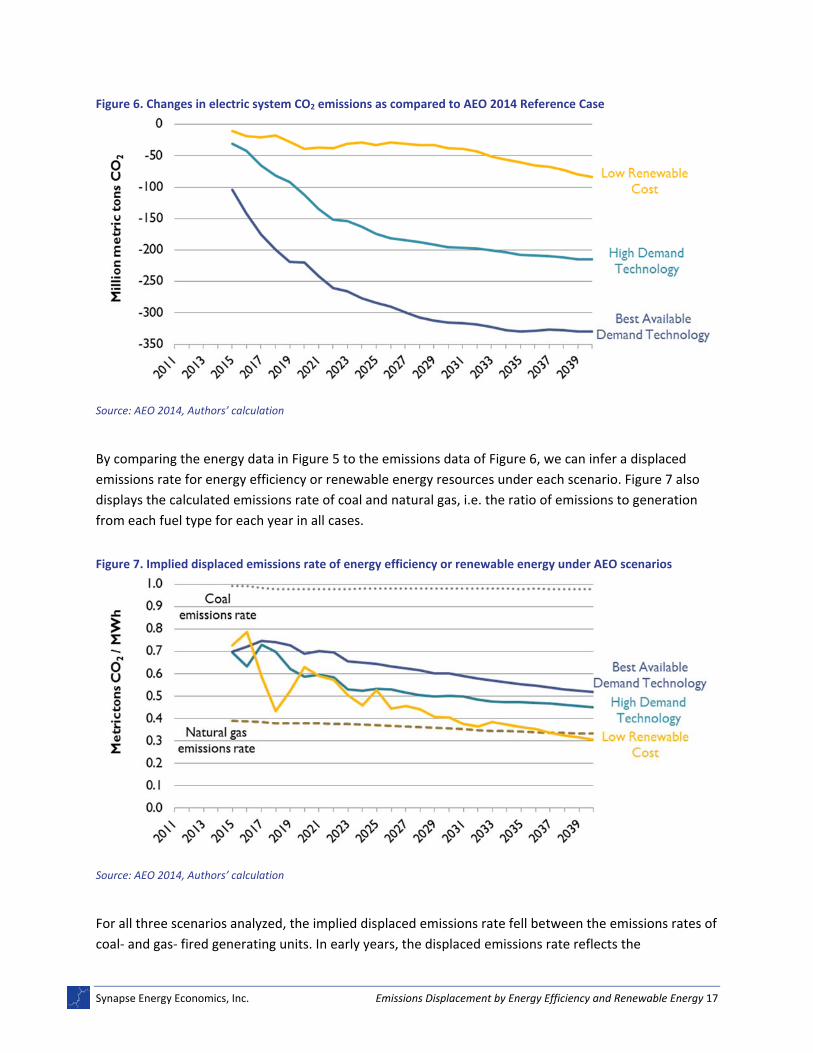
Figure 6. Changes in electric system CO2 emissions as compared to AEO 2014 Reference Case
Source: AEO 2014, Authors’ calculation
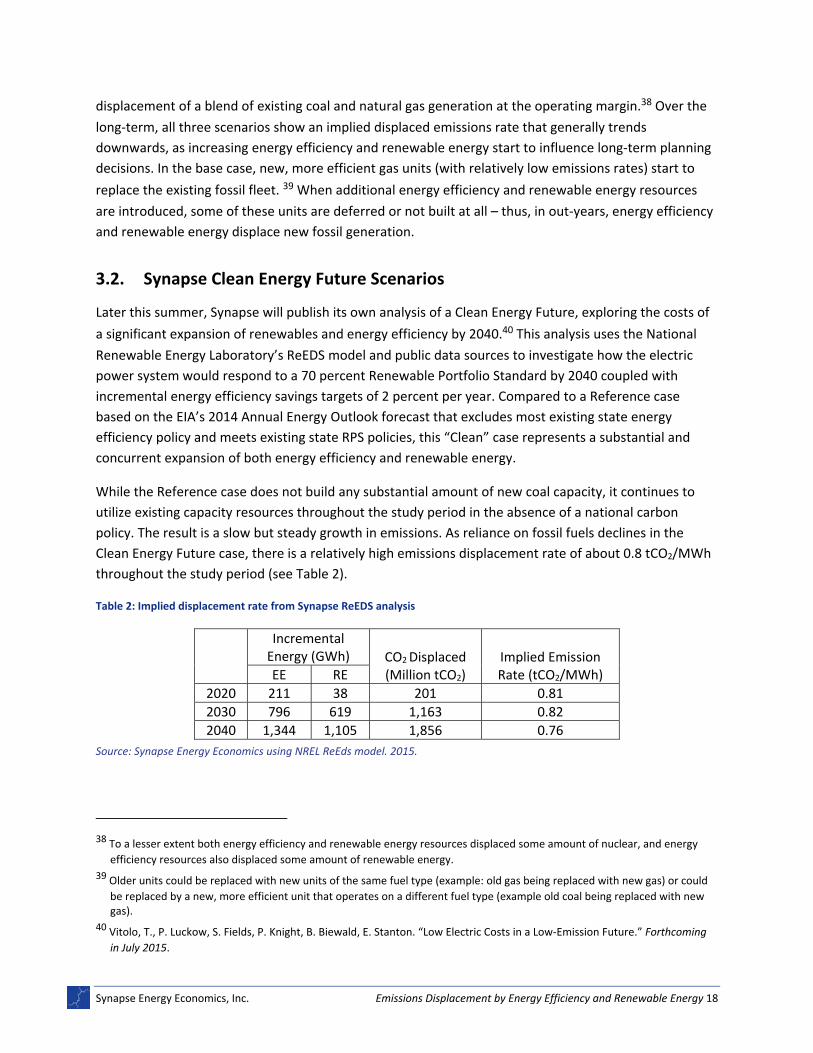
By comparing the energy data in Figure 5 to the emissions data of Figure 6, we can infer a displaced
emissions rate for energy efficiency or renewable energy resources under each scenario. Figure 7 also
displays the calculated emissions rate of coal and natural gas, i.e. the ratio of emissions to generation
from each fuel type for each year in all cases.
Figure 7. Implied displaced emissions rate of energy efficiency or renewable energy under AEO scenarios
Source: AEO 2014, Authors’ calculation
For all three scenarios analyzed, the implied displaced emissions rate fell between the emissions rates of
coal‐ and gas‐ fired generating units. In early years, the displaced emissions rate reflects the
Synapse Energy Economics, Inc. Emissions Displacement by Energy Efficiency and Renewable Energy 18
displacement of a blend of existing coal and natural gas generation at the operating margin.38 Over the
long‐term, all three scenarios show an implied displaced emissions rate that generally trends
downwards, as increasing energy efficiency and renewable energy start to influence long‐term planning
decisions. In the base case, new, more efficient gas units (with relatively low emissions rates) start to
replace the existing fossil fleet. 39 When additional energy efficiency and renewable energy resources
are introduced, some of these units are deferred or not built at all – thus, in out‐years, energy efficiency
and renewable energy displace new fossil generation.
3.2. Synapse Clean Energy Future Scenarios
Later this summer, Synapse will publish its own analysis of a Clean Energy Future, exploring the costs of
a significant expansion of renewables and energy efficiency by 2040.40 This analysis uses the National
Renewable Energy Laboratory’s ReEDS model and public data sources to investigate how the electric
power system would respond to a 70 percent Renewable Portfolio Standard by 2040 coupled with
incremental energy efficiency savings targets of 2 percent per year. Compared to a Reference case
based on the EIA’s 2014 Annual Energy Outlook forecast that excludes most existing state energy
efficiency policy and meets existing state RPS policies, this “Clean” case represents a substantial and
concurrent expansion of both energy efficiency and renewable energy.
While the Reference case does not build any substantial amount of new coal capacity, it continues to
utilize existing capacity resources throughout the study period in the absence of a national carbon
policy. The result is a slow but steady growth in emissions. As reliance on fossil fuels declines in the
Clean Energy Future case, there is a relatively high emissions displacement rate of about 0.8 tCO2/MWh
throughout the study period (see Table 2).
Table 2: Implied displacement rate from Synapse ReEDS analysis
Incremental Energy (GWh) CO2 Displaced
(Million tCO2) Implied Emission Rate (tCO2/MWh) EE RE
2020 211 38 201 0.81
2030 796 619 1,163 0.82
2040 1,344 1,105 1,856 0.76
Source: Synapse Energy Economics using NREL ReEds model. 2015.
38 To a lesser extent both energy efficiency and renewable energy resources displaced some amount of nuclear, and energy
efficiency resources also displaced some amount of renewable energy.
39 Older units could be replaced with new units of the same fuel type (example: old gas being replaced with new gas) or could
be replaced by a new, more efficient unit that operates on a different fuel type (example old coal being replaced with new gas).
40 Vitolo, T., P. Luckow, S. Fields, P. Knight, B. Biewald, E. Stanton. “Low Electric Costs in a Low‐Emission Future.” Forthcoming
in July 2015.
Synapse Energy Economics, Inc. Emissions Displacement by Energy Efficiency and Renewable Energy 19
As discussed at the beginning of this section, caveats apply to using national studies done for different
purposes to infer a displacement emissions rate. In addition to a mandated level of energy efficiency
and renewable energy in the Synapse Clean Energy Future, an expansion of electric vehicles was
assumed, as well as increased utilization of demand response resources. The impact of these factors is
difficult to disaggregate from other effects—electric vehicles push demand up overall, increasing the
utilization of existing fossil resources, as well as the demand for new energy efficiency or renewable
energy resources. Demand response reduces the peak demand, which is typically composed of less
efficient fossil resources, but represents a very small portion of the overall annual emissions and
generation.
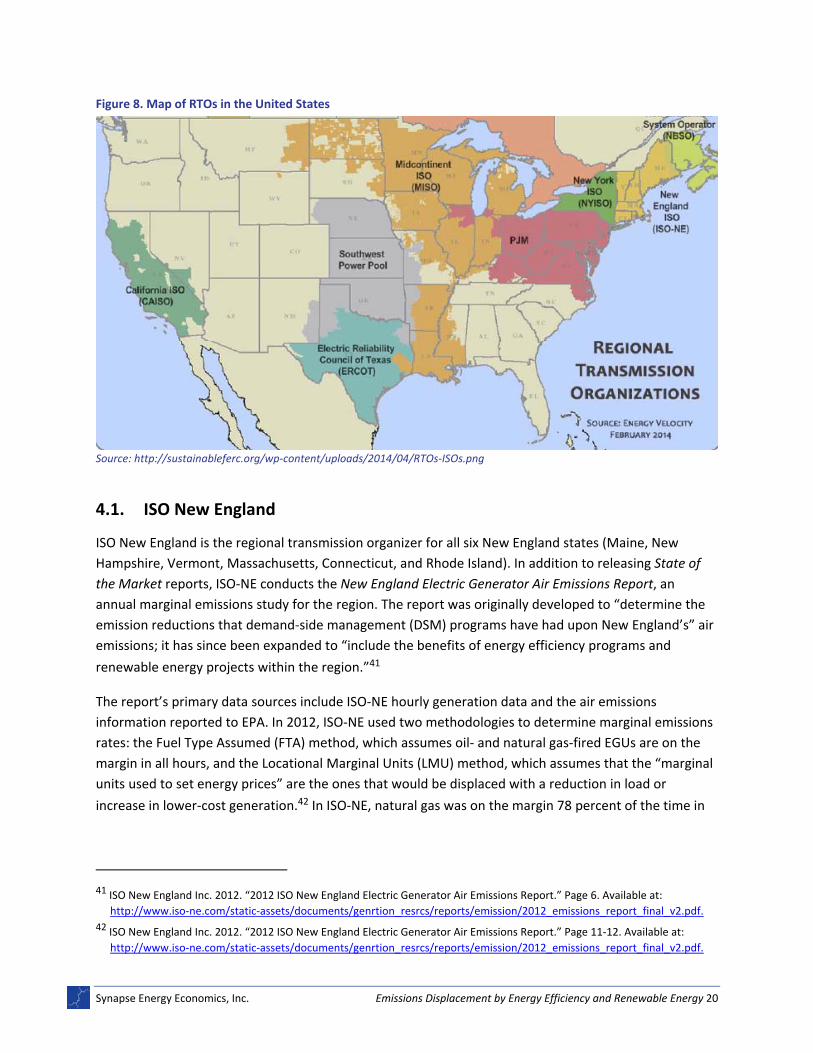
4. REGIONAL STUDIES
Displaced emissions from energy efficiency and renewable energy can be inferred from reports provided
by electric system operators. Within the United States, there are seven regional transmission
organizations (RTOs) that operate the electric grid: ISO New England (ISO‐NE), New York ISO (NYISO),
PJM Interconnection (PJM), Midcontinent ISO (MISO), Southwest Power Pool (SPP), Electric Reliability
Council of Texas (ERCOT), and California ISO (CAISO). Multiple utilities operate within each of these
RTOs, but the RTO is responsible for dispatching electricity over large areas (typically across state lines).
Each of the RTOs publishes “State of the Market” reports, which detail important market information
including locational marginal prices. Many of the reports include information about marginal fuels
and/or emissions, often with the purpose of helping to determine emissions reductions from energy
efficiency and renewable energy programs. This chapter reviews the findings of the four that have
recently published marginal fuel and/or marginal emissions reports. The studies conducted by the RTOs
focus on dispatchable, supply‐side resources (including demand response) but do not look at demand‐
side resources like energy efficiency or net metered renewable energy.
Synapse Energy Economics, Inc. Emissions Displacement by Energy Efficiency and Renewable Energy 20
44 Determination of the type of marginal resource is based on primary fuel type. For generating units that are capable of
generating electricity from more than one fuel type, PJM does not require the disclosure of fuel type associated with bid offer. PJM’s State of the Market report does not appear to differentiate between combined cycle, combustion turbine, and steam turbine units. Due to transmission constraints, it is possible that there is more than one marginal unit at any one moment.
Synapse Energy Economics, Inc. Emissions Displacement by Energy Efficiency and Renewable Energy 22
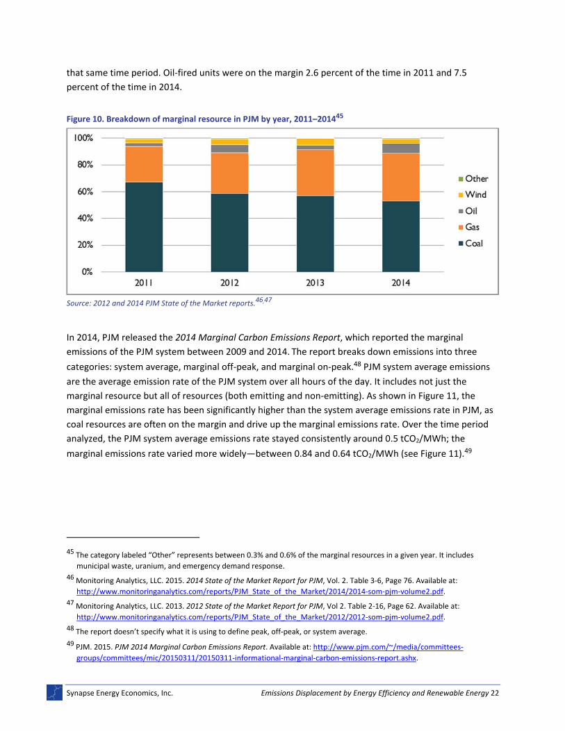
that same time period. Oil‐fired units were on the margin 2.6 percent of the time in 2011 and 7.5
percent of the time in 2014.
Figure 10. Breakdown of marginal resource in PJM by year, 2011–201445
Source: 2012 and 2014 PJM State of the Market reports.46,47
In 2014, PJM released the 2014 Marginal Carbon Emissions Report, which reported the marginal
emissions of the PJM system between 2009 and 2014. The report breaks down emissions into three
categories: system average, marginal off‐peak, and marginal on‐peak.48 PJM system average emissions
are the average emission rate of the PJM system over all hours of the day. It includes not just the
marginal resource but all of resources (both emitting and non‐emitting). As shown in Figure 11, the
marginal emissions rate has been significantly higher than the system average emissions rate in PJM, as
coal resources are often on the margin and drive up the marginal emissions rate. Over the time period
analyzed, the PJM system average emissions rate stayed consistently around 0.5 tCO2/MWh; the
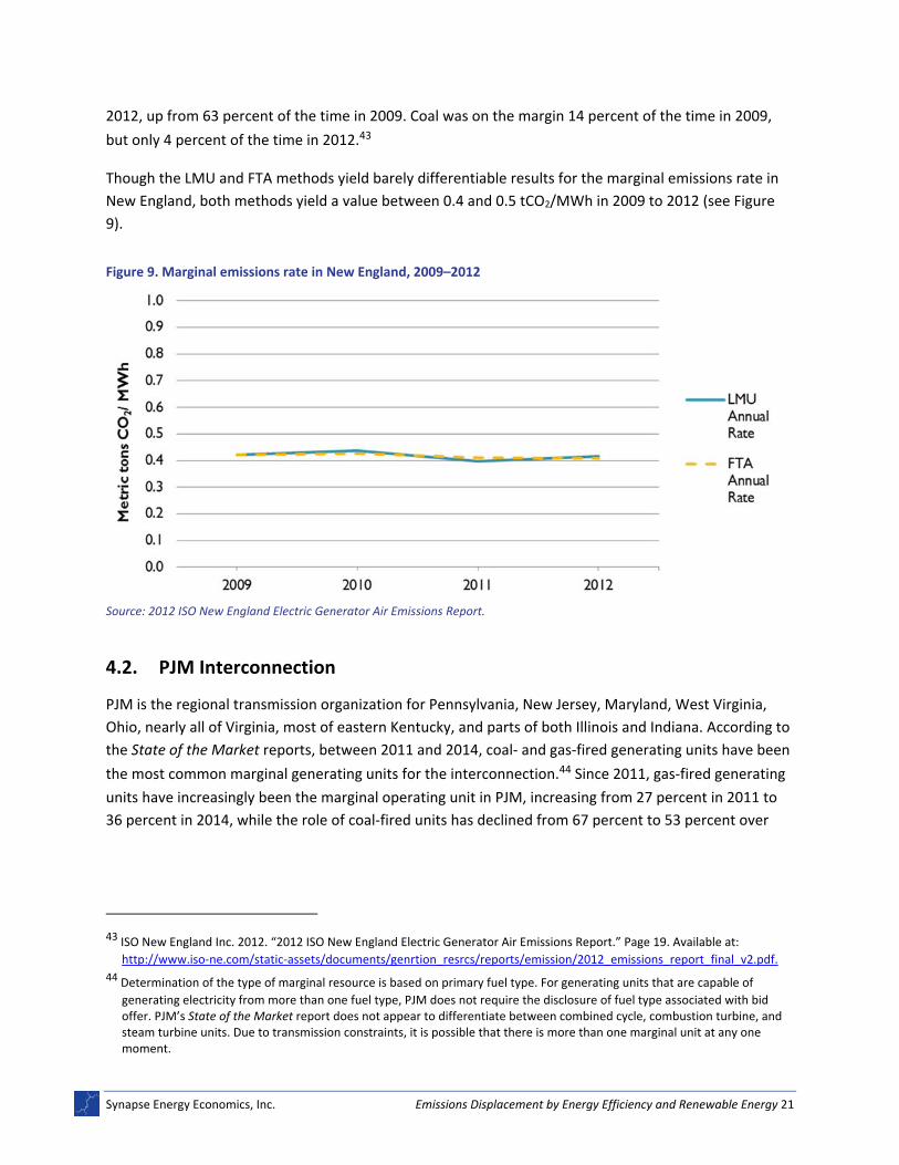
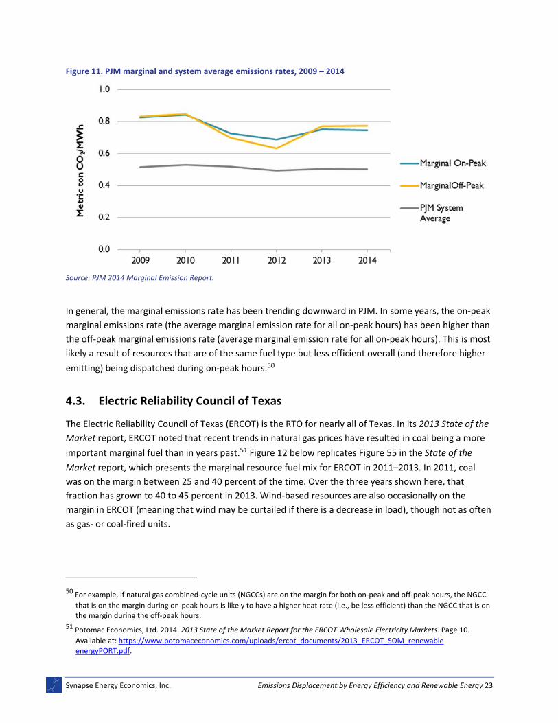
marginal emissions rate varied more widely—between 0.84 and 0.64 tCO2/MWh (see Figure 11).49
45 The category labeled “Other” represents between 0.3% and 0.6% of the marginal resources in a given year. It includes
municipal waste, uranium, and emergency demand response.
46 Monitoring Analytics, LLC. 2015. 2014 State of the Market Report for PJM, Vol. 2. Table 3‐6, Page 76. Available at:
Synapse Energy Economics, Inc. Emissions Displacement by Energy Efficiency and Renewable Energy 23
Figure 11. PJM marginal and system average emissions rates, 2009 – 2014
Source: PJM 2014 Marginal Emission Report.
In general, the marginal emissions rate has been trending downward in PJM. In some years, the on‐peak
marginal emissions rate (the average marginal emission rate for all on‐peak hours) has been higher than
the off‐peak marginal emissions rate (average marginal emission rate for all on‐peak hours). This is most
likely a result of resources that are of the same fuel type but less efficient overall (and therefore higher
emitting) being dispatched during on‐peak hours.50
4.3. Electric Reliability Council of Texas
The Electric Reliability Council of Texas (ERCOT) is the RTO for nearly all of Texas. In its 2013 State of the
Market report, ERCOT noted that recent trends in natural gas prices have resulted in coal being a more
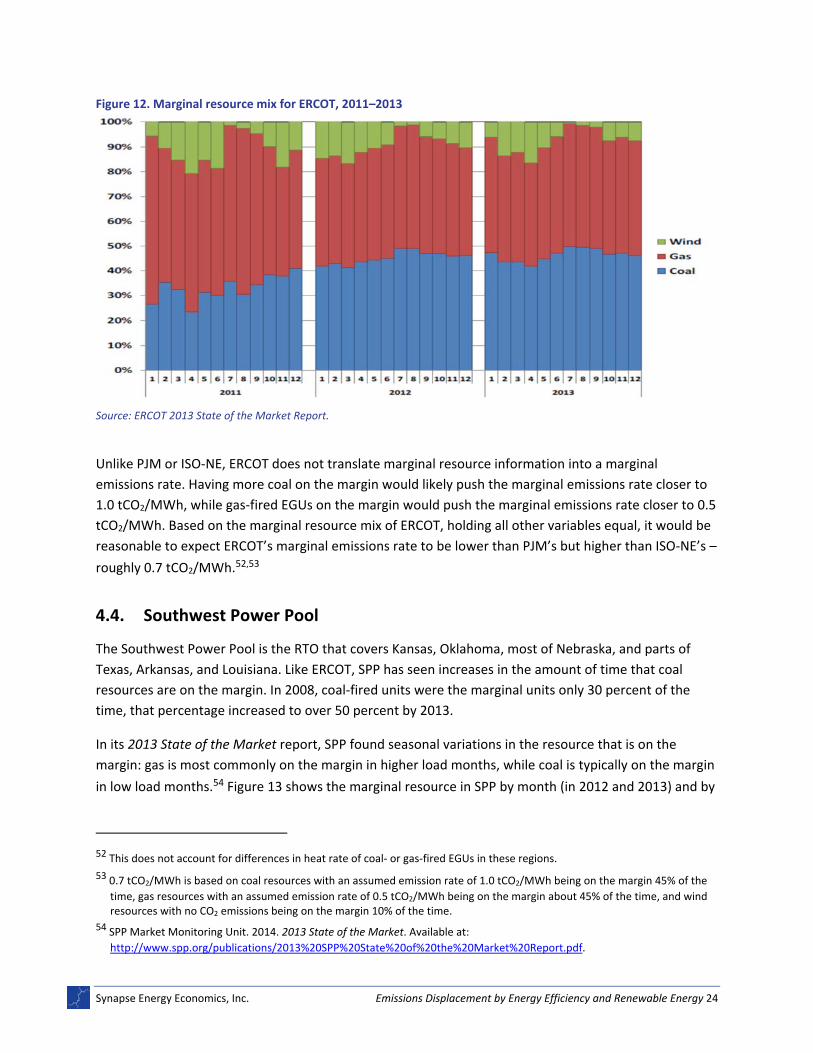
important marginal fuel than in years past.51 Figure 12 below replicates Figure 55 in the State of the
Market report, which presents the marginal resource fuel mix for ERCOT in 2011–2013. In 2011, coal
was on the margin between 25 and 40 percent of the time. Over the three years shown here, that
fraction has grown to 40 to 45 percent in 2013. Wind‐based resources are also occasionally on the
margin in ERCOT (meaning that wind may be curtailed if there is a decrease in load), though not as often
as gas‐ or coal‐fired units.
50 For example, if natural gas combined‐cycle units (NGCCs) are on the margin for both on‐peak and off‐peak hours, the NGCC
that is on the margin during on‐peak hours is likely to have a higher heat rate (i.e., be less efficient) than the NGCC that is on the margin during the off‐peak hours.
51 Potomac Economics, Ltd. 2014. 2013 State of the Market Report for the ERCOT Wholesale Electricity Markets. Page 10.
Available at: https://www.potomaceconomics.com/uploads/ercot_documents/2013_ERCOT_SOM_renewable energyPORT.pdf.
Synapse Energy Economics, Inc. Emissions Displacement by Energy Efficiency and Renewable Energy 24
Figure 12. Marginal resource mix for ERCOT, 2011–2013
Source: ERCOT 2013 State of the Market Report.
Unlike PJM or ISO‐NE, ERCOT does not translate marginal resource information into a marginal
emissions rate. Having more coal on the margin would likely push the marginal emissions rate closer to
1.0 tCO2/MWh, while gas‐fired EGUs on the margin would push the marginal emissions rate closer to 0.5
tCO2/MWh. Based on the marginal resource mix of ERCOT, holding all other variables equal, it would be
reasonable to expect ERCOT’s marginal emissions rate to be lower than PJM’s but higher than ISO‐NE’s –
roughly 0.7 tCO2/MWh.52,53
4.4. Southwest Power Pool
The Southwest Power Pool is the RTO that covers Kansas, Oklahoma, most of Nebraska, and parts of
Texas, Arkansas, and Louisiana. Like ERCOT, SPP has seen increases in the amount of time that coal
resources are on the margin. In 2008, coal‐fired units were the marginal units only 30 percent of the
time, that percentage increased to over 50 percent by 2013.
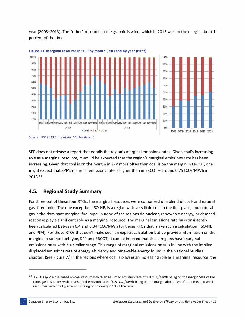
In its 2013 State of the Market report, SPP found seasonal variations in the resource that is on the
margin: gas is most commonly on the margin in higher load months, while coal is typically on the margin
in low load months.54 Figure 13 shows the marginal resource in SPP by month (in 2012 and 2013) and by
52 This does not account for differences in heat rate of coal‐ or gas‐fired EGUs in these regions.
53 0.7 tCO2/MWh is based on coal resources with an assumed emission rate of 1.0 tCO2/MWh being on the margin 45% of the
time, gas resources with an assumed emission rate of 0.5 tCO2/MWh being on the margin about 45% of the time, and wind resources with no CO2 emissions being on the margin 10% of the time.
54 SPP Market Monitoring Unit. 2014. 2013 State of the Market. Available at:
Synapse Energy Economics, Inc. Emissions Displacement by Energy Efficiency and Renewable Energy 25
year (2008–2013). The “other” resource in the graphic is wind, which in 2013 was on the margin about 1
percent of the time.
Figure 13. Marginal resource in SPP: by month (left) and by year (right)
Source: SPP 2013 State of the Market Report.
SPP does not release a report that details the region’s marginal emissions rates. Given coal’s increasing
role as a marginal resource, it would be expected that the region’s marginal emissions rate has been
increasing. Given that coal is on the margin in SPP more often than coal is on the margin in ERCOT, one
might expect that SPP’s marginal emissions rate is higher than in ERCOT – around 0.75 tCO2/MWh in
2013.55
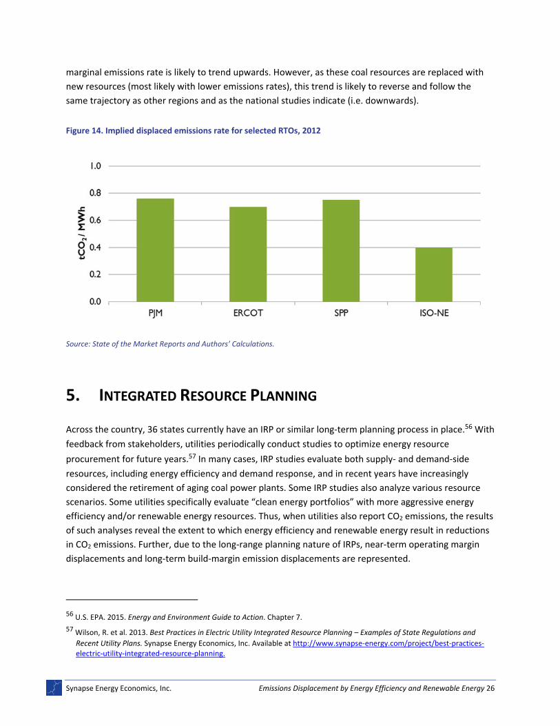
4.5. Regional Study Summary
For three out of these four RTOs, the marginal resources were comprised of a blend of coal‐ and natural
gas‐ fired units. The one exception, ISO‐NE, is a region with very little coal in the first place, and natural
gas is the dominant marginal fuel type. In none of the regions do nuclear, renewable energy, or demand
response play a significant role as a marginal resource. The marginal emissions rate has consistently
been calculated between 0.4 and 0.84 tCO2/MWh for those RTOs that make such a calculation (ISO‐NE
and PJM). For those RTOs that don’t make such an explicit calculation but do provide information on the
marginal resource fuel type, SPP and ERCOT, it can be inferred that these regions have marginal
emissions rates within a similar range. This range of marginal emissions rates is in line with the implied
displaced emissions rate of energy efficiency and renewable energy found in the National Studies
chapter. (See Figure 7.) In the regions where coal is playing an increasing role as a marginal resource, the
55 0.75 tCO2/MWh is based on coal resources with an assumed emission rate of 1.0 tCO2/MWh being on the margin 50% of the
time, gas resources with an assumed emission rate of 0.5 tCO2/MWh being on the margin about 49% of the time, and wind resources with no CO2 emissions being on the margin 1% of the time.
Synapse Energy Economics, Inc. Emissions Displacement by Energy Efficiency and Renewable Energy 26
marginal emissions rate is likely to trend upwards. However, as these coal resources are replaced with
new resources (most likely with lower emissions rates), this trend is likely to reverse and follow the
same trajectory as other regions and as the national studies indicate (i.e. downwards).
Figure 14. Implied displaced emissions rate for selected RTOs, 2012
Source: State of the Market Reports and Authors’ Calculations.
5. INTEGRATED RESOURCE PLANNING
Across the country, 36 states currently have an IRP or similar long‐term planning process in place.56 With
feedback from stakeholders, utilities periodically conduct studies to optimize energy resource
procurement for future years.57 In many cases, IRP studies evaluate both supply‐ and demand‐side
resources, including energy efficiency and demand response, and in recent years have increasingly
considered the retirement of aging coal power plants. Some IRP studies also analyze various resource
scenarios. Some utilities specifically evaluate “clean energy portfolios” with more aggressive energy
efficiency and/or renewable energy resources. Thus, when utilities also report CO2 emissions, the results
of such analyses reveal the extent to which energy efficiency and renewable energy result in reductions
in CO2 emissions. Further, due to the long‐range planning nature of IRPs, near‐term operating margin
displacements and long‐term build‐margin emission displacements are represented.
56 U.S. EPA. 2015. Energy and Environment Guide to Action. Chapter 7.
57 Wilson, R. et al. 2013. Best Practices in Electric Utility Integrated Resource Planning – Examples of State Regulations and
Recent Utility Plans. Synapse Energy Economics, Inc. Available at http://www.synapse‐energy.com/project/best‐practices‐electric‐utility‐integrated‐resource‐planning.
Synapse Energy Economics, Inc. Emissions Displacement by Energy Efficiency and Renewable Energy 27
We identified three studies by large, predominant utilities (Tennessee Valley Authority, PacifiCorp, and
Duke Energy Carolinas) that provide both the annual changes in energy mix and CO2 emissions for one or
more clean energy portfolio relative to utility‐defined “base case” portfolios. This chapter summarizes
the findings of our review of these three IRP studies on generation mix and CO2 emissions.
5.1. Tennessee Valley Authority 2015 IRP
Tennessee Valley Authority (TVA) is a federally owned corporation created by congressional charter in
1933. TVA provides flood control, electricity generation, and economic development throughout the
Valley. TVA has the largest public power system in the nation, consisting of various types of generating
resources including 41 coal‐fired units, six nuclear units, 109 conventional hydro power units, four
Synapse Energy Economics, Inc. Emissions Displacement by Energy Efficiency and Renewable Energy 30
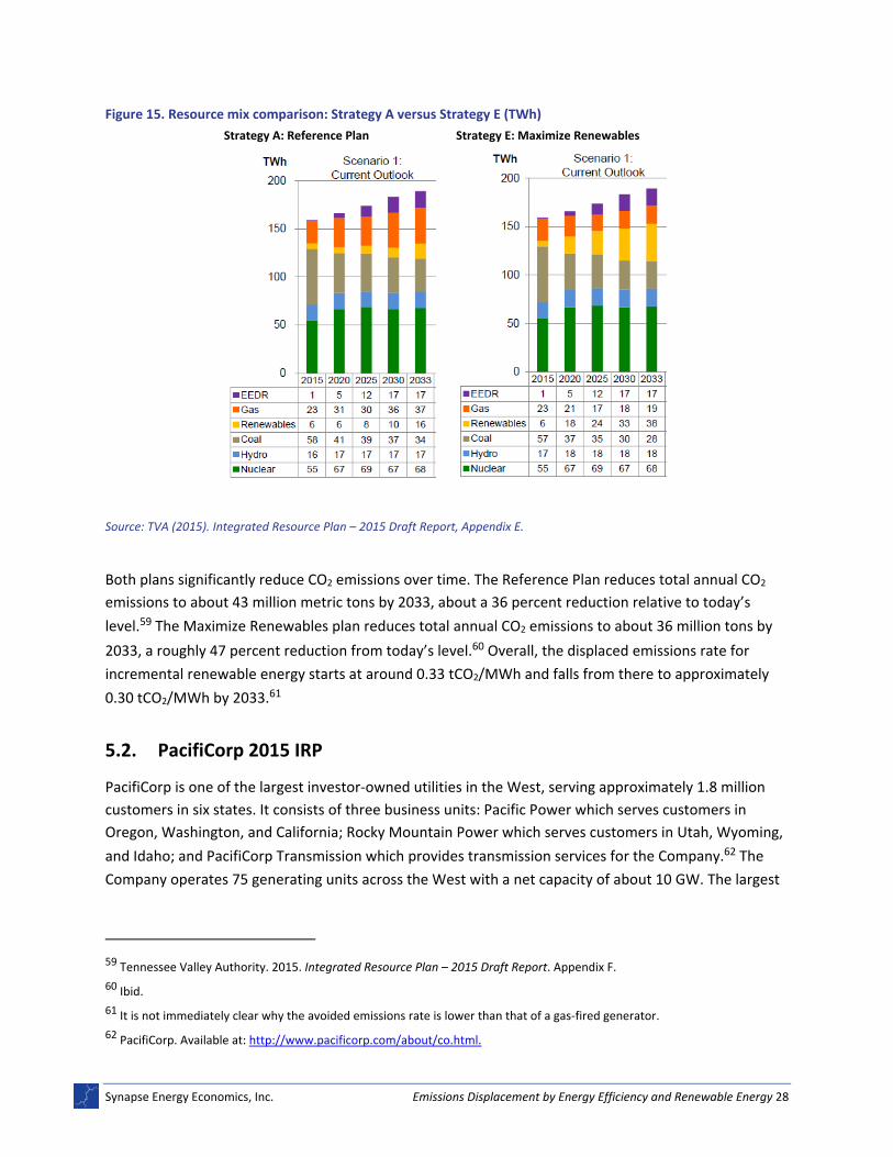
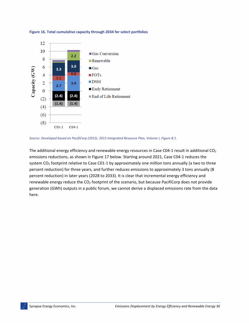
Figure 16. Total cumulative capacity through 2034 for select portfolios
Source: Developed based on PacifiCorp (2015). 2015 Integrated Resource Plan, Volume I, Figure 8.1.
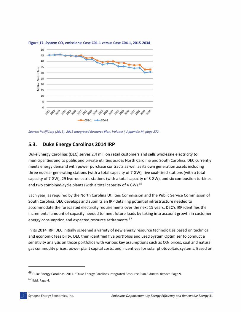
The additional energy efficiency and renewable energy resources in Case C04‐1 result in additional CO2
emissions reductions, as shown in Figure 17 below. Starting around 2021, Case C04‐1 reduces the
system CO2 footprint relative to Case C01‐1 by approximately one million tons annually (a two to three
percent reduction) for three years, and further reduces emissions to approximately 3 tons annually (8
percent reduction) in later years (2028 to 2033). It is clear that incremental energy efficiency and
renewable energy reduce the CO2 footprint of the scenario, but because PacifiCorp does not provide
generation (GWh) outputs in a public forum, we cannot derive a displaced emissions rate from the data
here.
Synapse Energy Economics, Inc. Emissions Displacement by Energy Efficiency and Renewable Energy 31
Figure 17. System CO2 emissions: Case C01‐1 versus Case C04‐1, 2015‐2034
Source: PacifiCorp (2015). 2015 Integrated Resource Plan, Volume I, Appendix M, page 272.
5.3. Duke Energy Carolinas 2014 IRP
Duke Energy Carolinas (DEC) serves 2.4 million retail customers and sells wholesale electricity to
municipalities and to public and private utilities across North Carolina and South Carolina. DEC currently
meets energy demand with power purchase contracts as well as its own generation assets including
three nuclear generating stations (with a total capacity of 7 GW), five coal‐fired stations (with a total
capacity of 7 GW), 29 hydroelectric stations (with a total capacity of 3 GW), and six combustion turbines
and two combined‐cycle plants (with a total capacity of 4 GW).66
Each year, as required by the North Carolina Utilities Commission and the Public Service Commission of
South Carolina, DEC develops and submits an IRP detailing potential infrastructure needed to
accommodate the forecasted electricity requirements over the next 15 years. DEC’s IRP identifies the
incremental amount of capacity needed to meet future loads by taking into account growth in customer
energy consumption and expected resource retirements.67
In its 2014 IRP, DEC initially screened a variety of new energy resource technologies based on technical
and economic feasibility. DEC then identified five portfolios and used System Optimizer to conduct a
sensitivity analysis on those portfolios with various key assumptions such as CO2 prices, coal and natural
gas commodity prices, power plant capital costs, and incentives for solar photovoltaic systems. Based on
66 Duke Energy Carolinas. 2014. “Duke Energy Carolinas Integrated Resource Plan.” Annual Report. Page 9.
67 Ibid. Page 4.
Synapse Energy Economics, Inc. Emissions Displacement by Energy Efficiency and Renewable Energy 32
this analysis, DEC finalized the five resource portfolios by determining the appropriate levels of different
resources under each portfolio.68
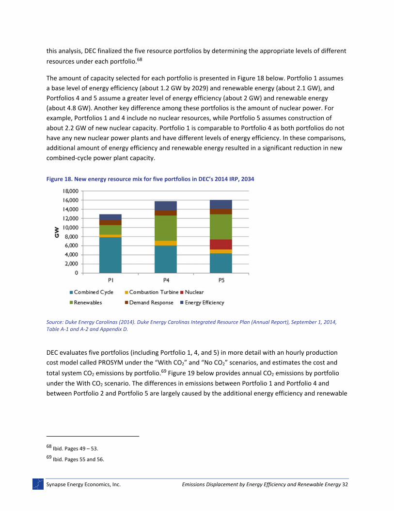
The amount of capacity selected for each portfolio is presented in Figure 18 below. Portfolio 1 assumes
a base level of energy efficiency (about 1.2 GW by 2029) and renewable energy (about 2.1 GW), and
Portfolios 4 and 5 assume a greater level of energy efficiency (about 2 GW) and renewable energy
(about 4.8 GW). Another key difference among these portfolios is the amount of nuclear power. For
example, Portfolios 1 and 4 include no nuclear resources, while Portfolio 5 assumes construction of
about 2.2 GW of new nuclear capacity. Portfolio 1 is comparable to Portfolio 4 as both portfolios do not
have any new nuclear power plants and have different levels of energy efficiency. In these comparisons,
additional amount of energy efficiency and renewable energy resulted in a significant reduction in new
combined‐cycle power plant capacity.
Figure 18. New energy resource mix for five portfolios in DEC’s 2014 IRP, 2034
Source: Duke Energy Carolinas (2014). Duke Energy Carolinas Integrated Resource Plan (Annual Report), September 1, 2014, Table A‐1 and A‐2 and Appendix D.
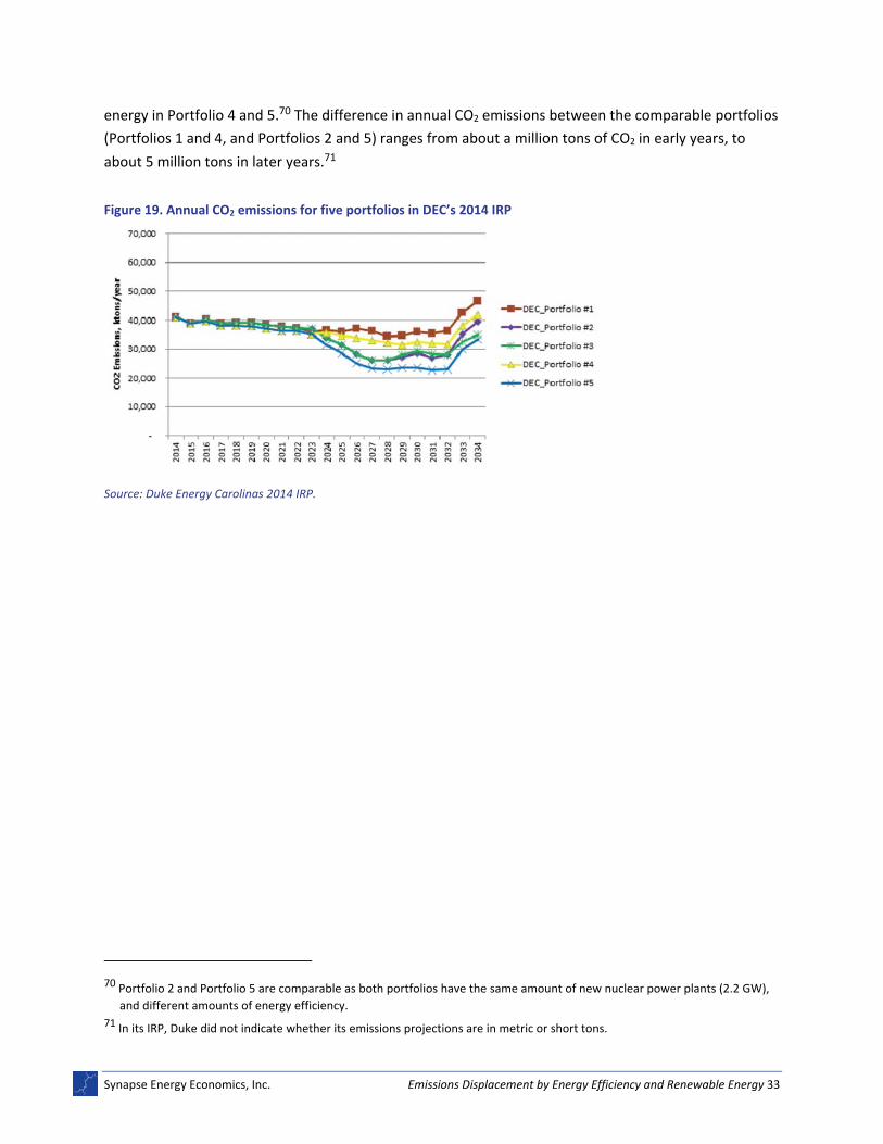
DEC evaluates five portfolios (including Portfolio 1, 4, and 5) in more detail with an hourly production
cost model called PROSYM under the “With CO2” and “No CO2” scenarios, and estimates the cost and
total system CO2 emissions by portfolio.69 Figure 19 below provides annual CO2 emissions by portfolio
under the With CO2 scenario. The differences in emissions between Portfolio 1 and Portfolio 4 and
between Portfolio 2 and Portfolio 5 are largely caused by the additional energy efficiency and renewable
68 Ibid. Pages 49 – 53.
69 Ibid. Pages 55 and 56.
Synapse Energy Economics, Inc. Emissions Displacement by Energy Efficiency and Renewable Energy 33
energy in Portfolio 4 and 5.70 The difference in annual CO2 emissions between the comparable portfolios
(Portfolios 1 and 4, and Portfolios 2 and 5) ranges from about a million tons of CO2 in early years, to
about 5 million tons in later years.71
Figure 19. Annual CO2 emissions for five portfolios in DEC’s 2014 IRP
Source: Duke Energy Carolinas 2014 IRP.
70 Portfolio 2 and Portfolio 5 are comparable as both portfolios have the same amount of new nuclear power plants (2.2 GW),
and different amounts of energy efficiency.
71 In its IRP, Duke did not indicate whether its emissions projections are in metric or short tons.
Synapse Energy Economics, Inc. Emissions Displacement by Energy Efficiency and Renewable Energy 34
6. QUANTIFYING EMISSIONS DISPLACEMENTS USING AVERT
6.1. Introduction
This chapter presents a sequence of case studies using EPA’s AVoided Emissions and geneRation Tool
(AVERT) to independently quantify the effect of energy efficiency and renewable energy programs on
displacing fossil‐based electricity and CO2 emissions in regions across the United States. In particular,
Synapse explored the following questions:
What role do new wind, utility‐scale solar PV, base load energy efficiency, and portfolio energy
efficiency resources play in displacing CO2 emissions from fossil‐based EGUs in different regions
across the United States?
How much have historical energy efficiency programs in the United States displaced CO2
emissions from fossil‐based EGUs?
Overall, results illustrate the pronounced effect energy efficiency and renewable energy has on
displacing electricity and emissions from fossil‐based generators. The larger the proportion of higher
carbon‐emitting resources in a region’s existing generation capacity mix, the larger a role energy
efficiency and renewable energy can play in displacing CO2 emissions. Additionally, the more these zero‐
emitting resources are implemented in a region, the larger is the volume of CO2 emissions displaced as a
percentage of total fossil EGU CO2 emissions. Due to the structure of AVERT, described in more detail
below, displaced electricity and emissions discussed in this chapter refer primarily to displacements
occurring at the operating margin (introduced in Chapter 1).
6.2. The AVoided Emissions and geneRation Tool (AVERT)
In 2014, Synapse Energy Economics developed AVERT under contract with EPA. The computer‐based
tool assists state and regional air quality managers, EPA, and other stakeholders estimate the extent to
which energy efficiency and renewable energy can displace emissions from fossil‐fired stationary
electrical generating units (EGUs). AVERT is free and publically available, and has a simple user interface;
non‐experts can easily evaluate county, state, and regional emissions displaced at electric power plants
from a wide range of energy efficiency and renewable energy policies and programs.72 The model
endured rigorous testing and external peer‐review prior to release.
AVERT is a unique class of model, designated as a “behavioral” simulator. Unlike traditional electricity
system simulation dispatch or production cost models, this model does not use operating costs to
estimate how and when a unit dispatches to meet load requirements. Rather, the model predicts unit
operation based on historical patterns and use. One significant advantage is that the model can be
driven entirely by historical, publicly available data: the actual generation output and emissions of real
72 AVERT, along with a user manual, is available for free download at www.epa.gov/avert.
Synapse Energy Economics, Inc. Emissions Displacement by Energy Efficiency and Renewable Energy 35
units in the recent past. Using this dataset only, the model replicates actual unit generation behaviors
such as base load, intermediate, and peaking behavior, units that have a must‐run designation (i.e. are
required to operate for reliability reasons, and often operate at minimum levels to maintain the ability
to meet load), as well as forced and maintenance outages. In addition, the model accurately represents
the relationship between unit generation and emissions, with characteristics such as a decreasing heat
rate (i.e. increasing efficiency) at higher levels of output, higher emissions from units that are just
warming up, and seasonally changing emissions for units with seasonal environmental controls. Analyses
are conducted by region, with the continental United States divided into 10 reasonably autonomous
electricity‐market trading and dispatch areas. These AVERT regions are based on aggregations of the
eGRID subregions used by EPA, and are similar, but not identical, to North American Electric Reliability
Corporation regions. Figure 20 shows a map of the model’s regions, several of which represent
electricity market areas or balancing authorities. The remainder of this chapter is dedicated to
presenting and discussing the results of the case studies.
Figure 20. U.S. regions represented in AVERT
Source: EPA.gov/AVERT.
6.3. Case Study 1: CO2 Emissions Displacement Potentials from Energy Efficiency and Renewable Energy Resources in 10 U.S. Regions
The first study exploits AVERT’s ability to evaluate displaced emission benefits at the unit level and at
hourly time‐steps in different regions across the United States. Different energy efficiency and
renewable energy resources have the potential to displace fossil EGU emissions in dissimilar ways. A
new wind power resource, for example, can disproportionately displace coal‐fired electricity generation
(and thus a larger quantity of emissions) because the wind typically blows stronger at nighttime—
periods of low demand when coal EGUs can be on the margin. In contrast, a wide‐ranging air
conditioning energy efficiency program can reduce a large amount of electricity demand during peak
load times. The purpose of this case study is to explore the relative effects of different energy efficiency
and renewable energy resources with different temporal profiles on displaced CO2 emissions in different
regions. To do so, Synapse evaluated four resource types—two energy efficiency resources, wind, and
Synapse Energy Economics, Inc. Emissions Displacement by Energy Efficiency and Renewable Energy 36
utility‐scale solar PV—entering their estimated profiles into AVERT for each region, and analyzing the
outputs.
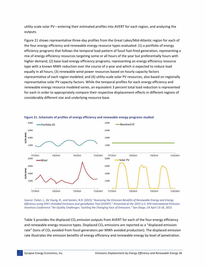
Figure 21 shows representative three‐day profiles from the Great Lakes/Mid‐Atlantic region for each of
the four energy efficiency and renewable energy resource types evaluated: (1) a portfolio of energy
efficiency programs that follows the temporal load pattern of fossil fuel‐fired generation, representing a
mix of energy efficiency resources targeting some or all hours of the year but preferentially hours with
higher demand; (2) base load energy efficiency programs, representing an energy efficiency resource
type with a known MWh reduction over the course of a year and which is expected to reduce load
equally in all hours; (3) renewable wind power resources based on hourly capacity factors
representative of each region modeled; and (4) utility‐scale solar PV resources, also based on regionally
representative solar PV capacity factors. While the temporal profiles for each energy efficiency and
renewable energy resource modeled varies, an equivalent 3 percent total load reduction is represented
for each in order to appropriately compare their respective displacement effects in different regions of
considerably different size and underlying resource base.
Figure 21. Schematic of profiles of energy efficiency and renewable energy programs studied
Source: Fisher, J., De Young, R., and Santen, N.R. (2015) “Assessing the Emission Benefits of Renewable Energy and Energy Efficiency using EPA’s AVoided Emissions and geneRation Tool (AVERT).” Presented at the 2015 U.S. EPA International Emission Inventory Conference "Air Quality Challenges: Tackling the Changing Face of Emissions.” San Diego, CA April 13‐16, 2015.
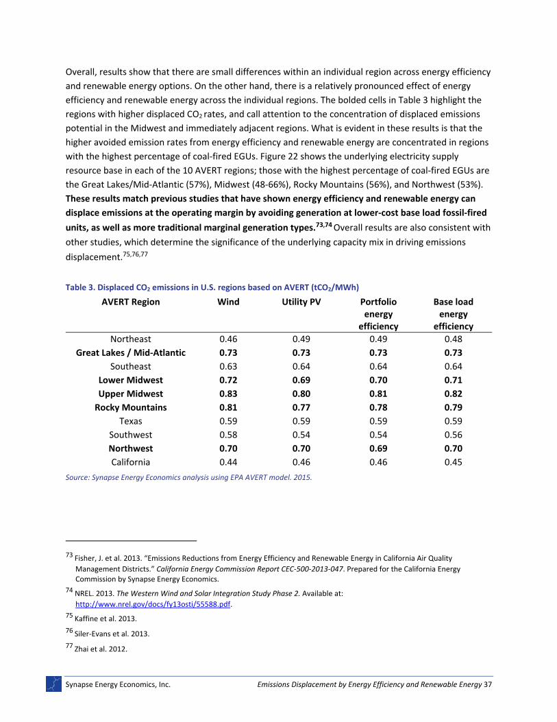
Table 3 provides the displaced CO2 emission outputs from AVERT for each of the four energy efficiency
and renewable energy resource types. Displaced CO2 emissions are reported as a “displaced emission
rate” (tons of CO2 avoided from fossil generators per MWh avoided production). The displaced emission
rate illustrates the emission benefits of energy efficiency and renewable energy by level of penetration.
Synapse Energy Economics, Inc. Emissions Displacement by Energy Efficiency and Renewable Energy 37
Overall, results show that there are small differences within an individual region across energy efficiency
and renewable energy options. On the other hand, there is a relatively pronounced effect of energy
efficiency and renewable energy across the individual regions. The bolded cells in Table 3 highlight the
regions with higher displaced CO2 rates, and call attention to the concentration of displaced emissions
potential in the Midwest and immediately adjacent regions. What is evident in these results is that the
higher avoided emission rates from energy efficiency and renewable energy are concentrated in regions
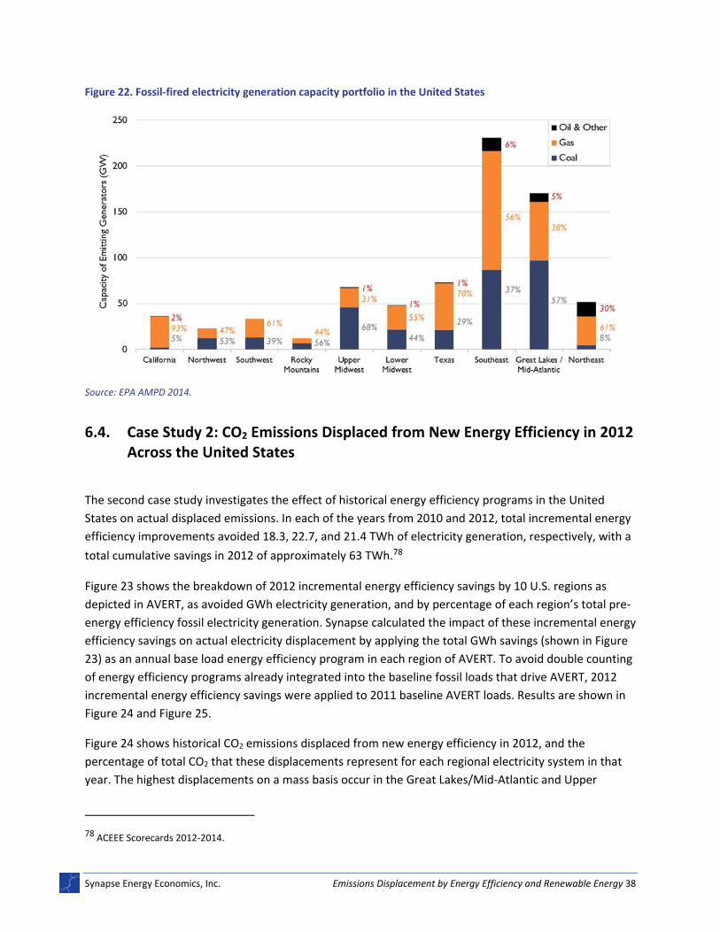
with the highest percentage of coal‐fired EGUs. Figure 22 shows the underlying electricity supply
resource base in each of the 10 AVERT regions; those with the highest percentage of coal‐fired EGUs are
the Great Lakes/Mid‐Atlantic (57%), Midwest (48‐66%), Rocky Mountains (56%), and Northwest (53%).
These results match previous studies that have shown energy efficiency and renewable energy can
displace emissions at the operating margin by avoiding generation at lower‐cost base load fossil‐fired
units, as well as more traditional marginal generation types.73,74 Overall results are also consistent with
other studies, which determine the significance of the underlying capacity mix in driving emissions
displacement.75,76,77
Table 3. Displaced CO2 emissions in U.S. regions based on AVERT (tCO2/MWh)
AVERT Region Wind Utility PV Portfolio energy
efficiency
Base load energy
efficiency
Northeast 0.46 0.49 0.49 0.48
Great Lakes / Mid‐Atlantic 0.73 0.73 0.73 0.73
Southeast 0.63 0.64 0.64 0.64
Lower Midwest 0.72 0.69 0.70 0.71
Upper Midwest 0.83 0.80 0.81 0.82
Rocky Mountains 0.81 0.77 0.78 0.79
Texas 0.59 0.59 0.59 0.59
Southwest 0.58 0.54 0.54 0.56
Northwest 0.70 0.70 0.69 0.70
California 0.44 0.46 0.46 0.45
Source: Synapse Energy Economics analysis using EPA AVERT model. 2015.
73 Fisher, J. et al. 2013. “Emissions Reductions from Energy Efficiency and Renewable Energy in California Air Quality
Management Districts.” California Energy Commission Report CEC‐500‐2013‐047. Prepared for the California Energy Commission by Synapse Energy Economics.
74 NREL. 2013. The Western Wind and Solar Integration Study Phase 2. Available at:
http://www.nrel.gov/docs/fy13osti/55588.pdf.
75 Kaffine et al. 2013.
76 Siler‐Evans et al. 2013.
77 Zhai et al. 2012.
Synapse Energy Economics, Inc. Emissions Displacement by Energy Efficiency and Renewable Energy 38
Figure 22. Fossil‐fired electricity generation capacity portfolio in the United States
Source: EPA AMPD 2014.
6.4. Case Study 2: CO2 Emissions Displaced from New Energy Efficiency in 2012 Across the United States
The second case study investigates the effect of historical energy efficiency programs in the United
States on actual displaced emissions. In each of the years from 2010 and 2012, total incremental energy
efficiency improvements avoided 18.3, 22.7, and 21.4 TWh of electricity generation, respectively, with a
total cumulative savings in 2012 of approximately 63 TWh.78
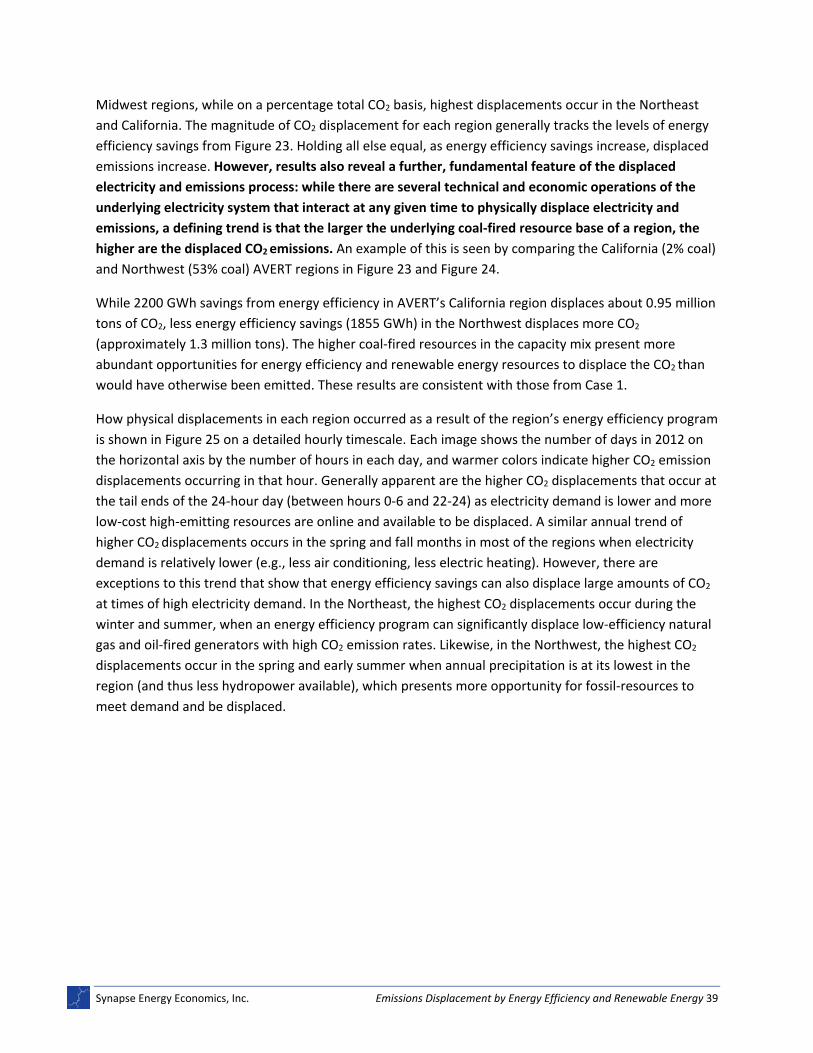
Figure 23 shows the breakdown of 2012 incremental energy efficiency savings by 10 U.S. regions as
depicted in AVERT, as avoided GWh electricity generation, and by percentage of each region’s total pre‐
energy efficiency fossil electricity generation. Synapse calculated the impact of these incremental energy
efficiency savings on actual electricity displacement by applying the total GWh savings (shown in Figure
23) as an annual base load energy efficiency program in each region of AVERT. To avoid double counting
of energy efficiency programs already integrated into the baseline fossil loads that drive AVERT, 2012
incremental energy efficiency savings were applied to 2011 baseline AVERT loads. Results are shown in
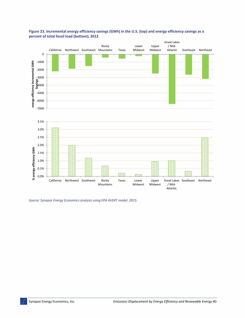
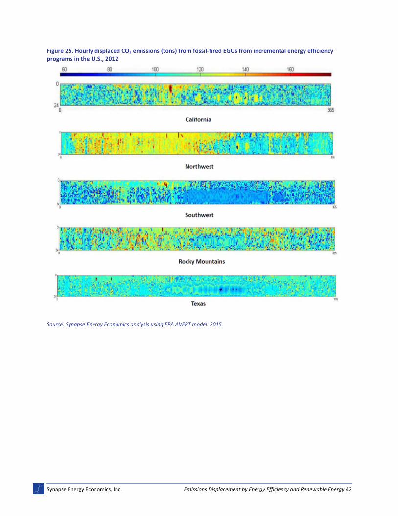
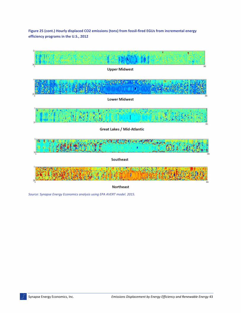
Figure 24 and Figure 25.
Figure 24 shows historical CO2 emissions displaced from new energy efficiency in 2012, and the
percentage of total CO2 that these displacements represent for each regional electricity system in that
year. The highest displacements on a mass basis occur in the Great Lakes/Mid‐Atlantic and Upper
78 ACEEE Scorecards 2012‐2014.
Synapse Energy Economics, Inc. Emissions Displacement by Energy Efficiency and Renewable Energy 39
Midwest regions, while on a percentage total CO2 basis, highest displacements occur in the Northeast
and California. The magnitude of CO2 displacement for each region generally tracks the levels of energy
efficiency savings from Figure 23. Holding all else equal, as energy efficiency savings increase, displaced
emissions increase. However, results also reveal a further, fundamental feature of the displaced
electricity and emissions process: while there are several technical and economic operations of the
underlying electricity system that interact at any given time to physically displace electricity and
emissions, a defining trend is that the larger the underlying coal‐fired resource base of a region, the
higher are the displaced CO2 emissions. An example of this is seen by comparing the California (2% coal)
and Northwest (53% coal) AVERT regions in Figure 23 and Figure 24.
While 2200 GWh savings from energy efficiency in AVERT’s California region displaces about 0.95 million
tons of CO2, less energy efficiency savings (1855 GWh) in the Northwest displaces more CO2
(approximately 1.3 million tons). The higher coal‐fired resources in the capacity mix present more
abundant opportunities for energy efficiency and renewable energy resources to displace the CO2 than
would have otherwise been emitted. These results are consistent with those from Case 1.
How physical displacements in each region occurred as a result of the region’s energy efficiency program
is shown in Figure 25 on a detailed hourly timescale. Each image shows the number of days in 2012 on
the horizontal axis by the number of hours in each day, and warmer colors indicate higher CO2 emission
displacements occurring in that hour. Generally apparent are the higher CO2 displacements that occur at
the tail ends of the 24‐hour day (between hours 0‐6 and 22‐24) as electricity demand is lower and more
low‐cost high‐emitting resources are online and available to be displaced. A similar annual trend of
higher CO2 displacements occurs in the spring and fall months in most of the regions when electricity
demand is relatively lower (e.g., less air conditioning, less electric heating). However, there are
exceptions to this trend that show that energy efficiency savings can also displace large amounts of CO2
at times of high electricity demand. In the Northeast, the highest CO2 displacements occur during the
winter and summer, when an energy efficiency program can significantly displace low‐efficiency natural
gas and oil‐fired generators with high CO2 emission rates. Likewise, in the Northwest, the highest CO2
displacements occur in the spring and early summer when annual precipitation is at its lowest in the
region (and thus less hydropower available), which presents more opportunity for fossil‐resources to
meet demand and be displaced.
Synapse Energy Economics, Inc. Emissions Displacement by Energy Efficiency and Renewable Energy 40
Figure 23. Incremental energy efficiency savings (GWh) in the U.S. (top) and energy efficiency savings as a percent of total fossil load (bottom), 2012
Source: Synapse Energy Economics analysis using EPA AVERT model. 2015.
‐7000
‐6000
‐5000
‐4000
‐3000
‐2000
‐1000
0
California Northwest SouthwestRocky
Mountains TexasLower
MidwestUpper
Midwest
Great Lakes/ Mid‐Atlantic Southeast Northeast
energy efficiency In
cremental G
Wh
Savings
0.0%
0.5%
1.0%
1.5%
2.0%
2.5%
3.0%
3.5%
California Northwest Southwest RockyMountains
Texas LowerMidwest
UpperMidwest
Great Lakes/ Mid‐Atlantic
Southeast Northeast% energy efficiency GWh
Synapse Energy Economics, Inc. Emissions Displacement by Energy Efficiency and Renewable Energy 41
Figure 24. CO2 emissions displaced by incremental energy efficiency programs in the U.S., 2012
Source: Synapse Energy Economics analysis using EPA AVERT model. 2015.
‐5000
‐4000
‐3000
‐2000
‐1000
0
California Northwest SouthwestRocky
Mountains TexasLower
MidwestUpper
Midwest
Great Lakes/ Mid‐Atlantic Southeast Northeast
Displaced CO2 Tons (1000s)
0.00%
0.50%
1.00%
1.50%
2.00%
2.50%
California Northwest Southwest RockyMountains
Texas LowerMidwest
UpperMidwest
Great Lakes/ Mid‐Atlantic
Southeast Northeast
Displaced CO2
Synapse Energy Economics, Inc. Emissions Displacement by Energy Efficiency and Renewable Energy 42
Figure 25. Hourly displaced CO2 emissions (tons) from fossil‐fired EGUs from incremental energy efficiency programs in the U.S., 2012
Source: Synapse Energy Economics analysis using EPA AVERT model. 2015.
Synapse Energy Economics, Inc. Emissions Displacement by Energy Efficiency and Renewable Energy 43
Figure 25 (cont.) Hourly displaced CO2 emissions (tons) from fossil‐fired EGUs from incremental energy
efficiency programs in the U.S., 2012
Source: Synapse Energy Economics analysis using EPA AVERT model. 2015.
Synapse Energy Economics, Inc. Emissions Displacement by Energy Efficiency and Renewable Energy A1
APPENDIX A: EXPANDED METHODS AND LITERATURE REVIEW
The following appendix provides details of many key studies cited in Chapter 2.3, providing an overview
of two common approaches for studying displaced emissions.
As noted, a large number of academic studies over the past decade have sought to estimate the
electricity generation displaced by energy efficiency and renewable energy, and the subsequent
displaced emissions.79,80,81,82,83,84,85,86,87,88,89,90,91,92,93,94 The majority of these studies integrate various
features that are known, or can be observed, about the underlying electricity system into quantitative
models that calculate the amount of electricity and emissions displaced in a system for given levels of
renewable energy and energy efficiency. Methods for evaluation vary, but are typically based in either
statistical approaches, or detailed optimization or simulation approaches.
The simplest of the statistical methods involves calculating an average emission rate using historical data
on all operating EGUs in a region to apply as the rate by which emissions are reduced in the future.
However, a more contemporary statistical approach is to statistically derive a marginal emissions rate to
represent the operating EGUs in a given region.
In a study of carbon emissions displacement from various end‐use efficiency measures in England and
Wales, Bettle, Pout, and Hitchen (2006) developed an approach using marginal emission factors that
consider particular seasons and times of day. While the authors found no systematic difference in the
79 Bettle, R., C.H. Pout, and E.R. Hitchin. 2000.
80 Cullen, J. 2013.
81 Kaffine, D.T., B.J. McBee, and J. Lieskovsky. 2013.
82 Siler‐Evans, K., I.L. Azevedo, M.G. Morgan, and J. Apt. 2013.
83 Hausman, E., J. Fisher, and B. Biewald. 2008.
84 High, C. and G. Neeraj. 2011.
85 Newcomer, A., S.A. Blumsack, J. Apt, L.B. Lave, and M.G. Morgan. 2008.
86 Rothschild, S. and A. Diem. 2009.
87 Zhai, P., P. Larsen, D. Millstein, S. Menon, and E. Masanet. 2012.
88 Denny, E. and M. O’Malley. 2006.
89 Denny, E. and M. O’Malley. 2007.
90 Denholm, P., R.M. Margolis, and J. M. Milford. 2009.
91 Fisher, J. et al. 2009.
92 Valentino, L., V. Valenzuela, A. Botterud, Z. Zhou, and G. Conzelmann. 2012.
93 NREL. 2013.
94 SEAI. 2012.
Synapse Energy Economics, Inc. Emissions Displacement by Energy Efficiency and Renewable Energy A2
total carbon emissions savings from different end‐use programs, their analysis confirmed that emission
displacement increases with the scale of demand reduction, and also exposed a correlation between
nighttime storage heater use and higher emission intensities implying that coal is on the margin during
nighttime winter months.
Cullen (2013) uses a more sophisticated statistical model to estimate the impact of wind generation in
Texas on CO2 displacement. His model extended typical statistical approaches and included network
congestion effects, changing efficiencies of fossil‐fuel generators over time, generator outages,
generator pricing strategies, fuel prices, as well as lagged variables for generator output over time to
control for the influence generator outputs can have on future output. Results conclude that wind
typically displaces natural gas combined‐cycle plants, and in some cases less efficient simple‐cycle
natural gas turbines.
Kaffine, McBee, and Lieskovsky (2013) also study the impact of wind generation in Texas on emissions
displacement in additional detail. The authors’ statistical approach involved using hourly generator and
emission data to implicitly account for the marginal unit of generation; they find that the underlying
generation portfolio of a region is a strong driver of displacement potential from wind. Amor et al.
(2014) use similar methods to study electricity prices and carbon emissions displacement resulting from
increasing wind generation in Ontario.
Finally, in a paper examining the impact of renewable energy on avoided health impacts, Siler‐Evans et
al. (2013) refined previous statistical methods even further using hourly incremental changes in
emissions against incremental changes in energy, and divided the year into numerous “bins” of total
generation to account for fundamentally different dispatch at different load levels. Their results
underscore the variation in displacement effects across different regions, and the manner in which it is
impacted by the specific type of renewable resource and meteorology, and the underlying electricity
generation capacity resource mix from which emissions are being displaced.
A second common approach to calculating displaced emissions from energy efficiency and renewable
energy resources uses, directly or indirectly, numerical electricity dispatch models. These models are
typically more complex simulation or optimization electricity dispatch models that represent the
detailed features of the underlying physical electrical system, costs, and operational constraints of
individual generators, transmission, and aspects of how the regional market is organized and run.
Zhai et al (2012) studied the potential for displaced emissions from a 10 percent penetration of solar PV
in the United States using the EnergyPLAN model, a medium‐resolution electricity dispatch optimization
model representing technologies in groups. The authors find carbon emissions displacement as driven
by the underlying generation capacity mix of a region, the emission rates of existing fossil plants, and PV
capacity factors that can be realized in different states. In an earlier study, Denny and O’Malley (2006)
used a similar approach with a dispatch optimization model to study displaced emissions potentials for a
system with wind power. They found that increased wind capacity displaced fossil emissions, and
confirmed this in a follow‐up study in 2007.
Synapse Energy Economics, Inc. Emissions Displacement by Energy Efficiency and Renewable Energy A3
Using still finer‐resolution production cost models with hourly chronological dispatch and unit‐
commitment to evaluate energy efficiency and renewable energy avoided emissions, Denholm,
Margolis, and Milford (2009) employ ABB’s PROSYM production cost model to evaluate how deep
penetrations of solar energy (up to 10 percent) in western U.S. states avoid generation and emissions
throughout the west. They find that in California, a state with a large fraction of natural gas EGUs, solar
PV displaces CO2 emissions from natural gas at the margin (and imports). However, in Colorado, which
generates and uses a substantial amount of coal‐fired power, emissions begin being displaced from coal
EGUs during non‐summer months and at higher PV penetrations (emissions from natural gas are still
displaced at lower PV penetrations).
Fisher et al. (2011) also used the PROSYM engine to test how a series of energy efficiency and renewable
energy projects in California could impact individual generators across the western United States,
specifically examining emissions reductions in California air districts. The authors found that, depending
on the location of the energy efficiency and renewable energy resource, avoided emissions could either
be highly localized or based on generators across state lines. Coal generators were also impacted more
than might be expected based on traditional indicators of marginal units.
Valentino et al. (2012) constructs an optimization model with unit‐commitment and electricity dispatch
to estimate emission reductions from increased wind power in Illinois. Results show that while wind
power can increase cycling of fossil‐based EGUs and thus short‐term emissions, overall the direction is
to reduce emissions from replacement of fossil‐fuel use.
The 2013 National Renewable Energy Laboratory’s Western Wind and Solar Integration Study used a
similar dispatch optimization modeling approach to understand the effects of wind power on thermal
plant cycling. The study documented little effect in emissions increases due to cycling, and that at
increasing levels of renewable energy, electricity from more traditional low cost resources such as coal
can be displaced.
Finally, in 2012 the Sustainable Energy Authority of Ireland (SEAI) released a study quantifying the effect
of fuel and CO2 emissions displacement from renewable energy. Using the PLEXOS production cost and
dispatch modeling platform, results showed sizeable CO2 displacement potential from renewable
energy, as much as the electricity demand of 780,000 Irish households; wind power was the largest