Air Flow Analysis in Pharmaceutical “Clean Rooms”. Patrick Phelps ( Flowsolve ) and Richard Rowe ( Clean Room Construction Ltd ). IPUC 8 - Luxembourg - May 2000. Air Flow Analysis in Pharmaceutical “Clean Rooms”. Industrial Context Health and Safety Issues - PowerPoint PPT Presentation
Air Flow Analysis in Air Flow Analysis in Pharmaceutical “Clean Pharmaceutical “Clean Rooms” Rooms” Patrick Phelps Patrick Phelps ( Flowsolve ( Flowsolve ) ) and and Richard Rowe Richard Rowe ( Clean Room Construction Ltd ) ( Clean Room Construction Ltd ) IPUC 8 - Luxembourg - May 2000 IPUC 8 - Luxembourg - May 2000
Transcript
Air Flow Analysis in Air Flow Analysis in Pharmaceutical “Clean Pharmaceutical “Clean
Rooms”Rooms”
Patrick Phelps Patrick Phelps
( Flowsolve( Flowsolve ))
andand
Richard RoweRichard Rowe
( Clean Room Construction ( Clean Room Construction Ltd )Ltd )
IPUC 8 - Luxembourg - May 2000IPUC 8 - Luxembourg - May 2000
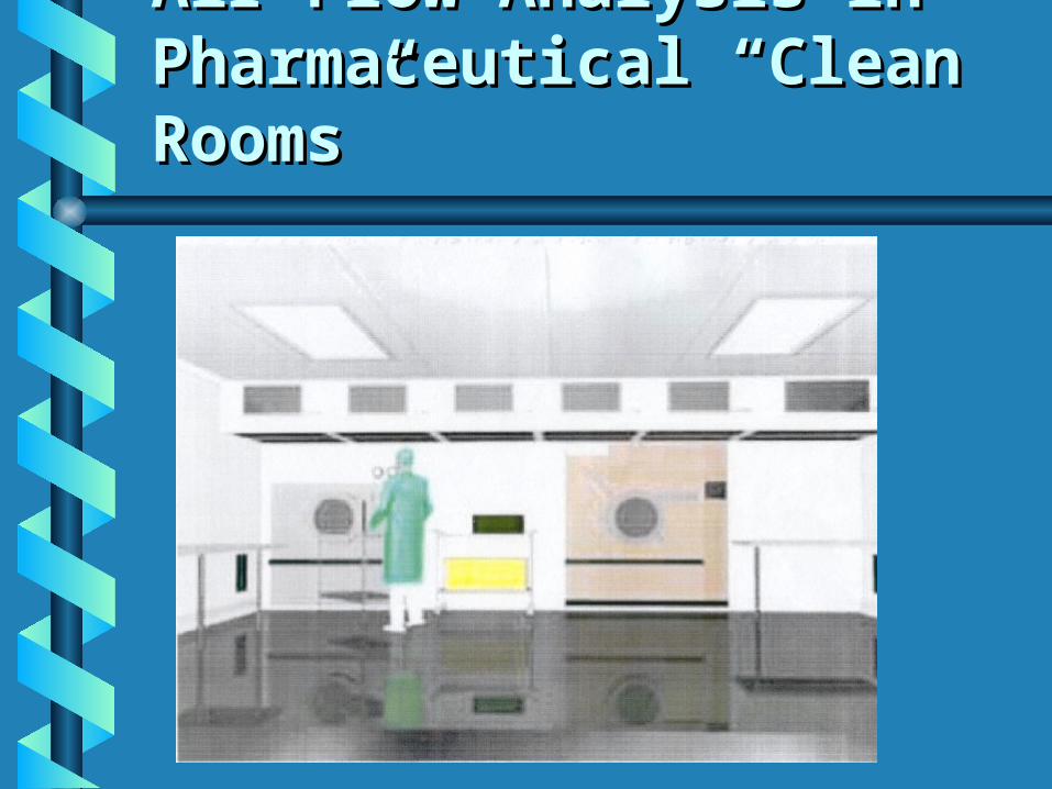
Air Flow Analysis in Air Flow Analysis in Pharmaceutical “Clean Pharmaceutical “Clean Rooms”Rooms”
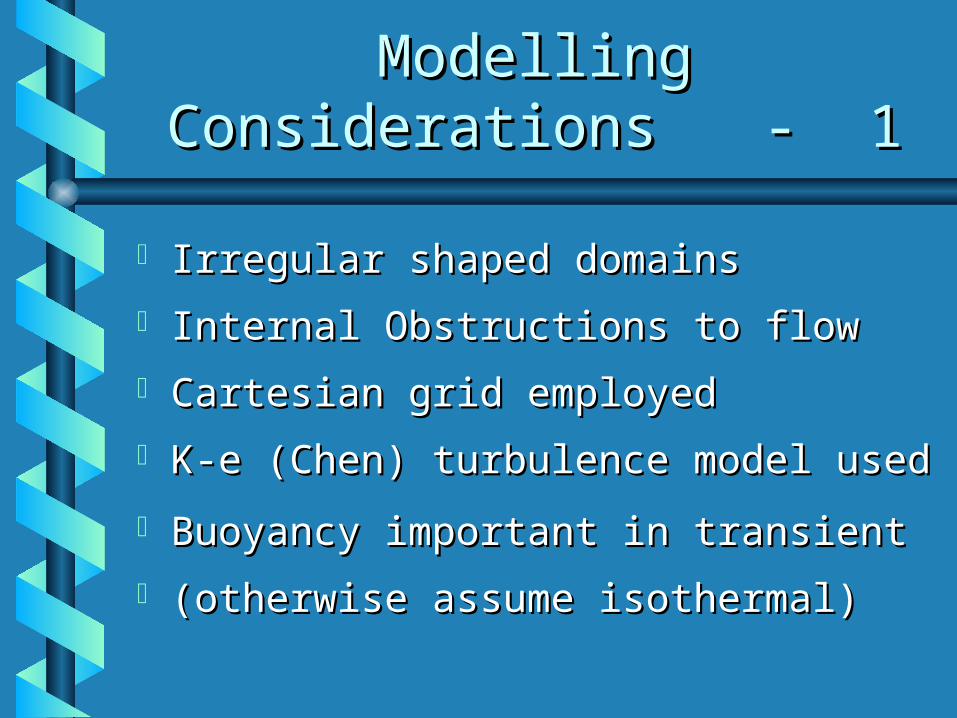
Industrial ContextIndustrial Context Health and Safety IssuesHealth and Safety Issues Application to an Existing RoomApplication to an Existing Room Application to New Ventilation Application to New Ventilation
preparation, processing and preparation, processing and packaging packaging
of pharmaceutical productsof pharmaceutical products
Strict codes of practice employed to Strict codes of practice employed to eradicate risk of product eradicate risk of product contaminationcontamination
Particular attention to ventilationParticular attention to ventilation
Ventilation of “Clean Ventilation of “Clean Rooms”Rooms”
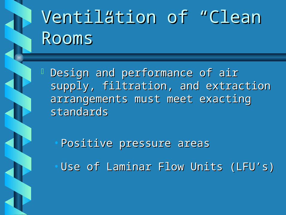
Design and performance of air Design and performance of air supply, filtration, and extraction supply, filtration, and extraction arrangements must meet exacting arrangements must meet exacting standardsstandards
• Positive pressure areasPositive pressure areas
• Use of Laminar Flow Units (LFU’s)Use of Laminar Flow Units (LFU’s)
“ “ Laminar Flow Units ”Laminar Flow Units ”
Devices which deliver a controlled Devices which deliver a controlled
down-draught of re-filtered air down-draught of re-filtered air
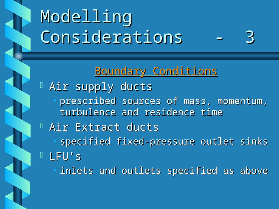
LFU’sLFU’s• inlets and outlets specified as aboveinlets and outlets specified as above
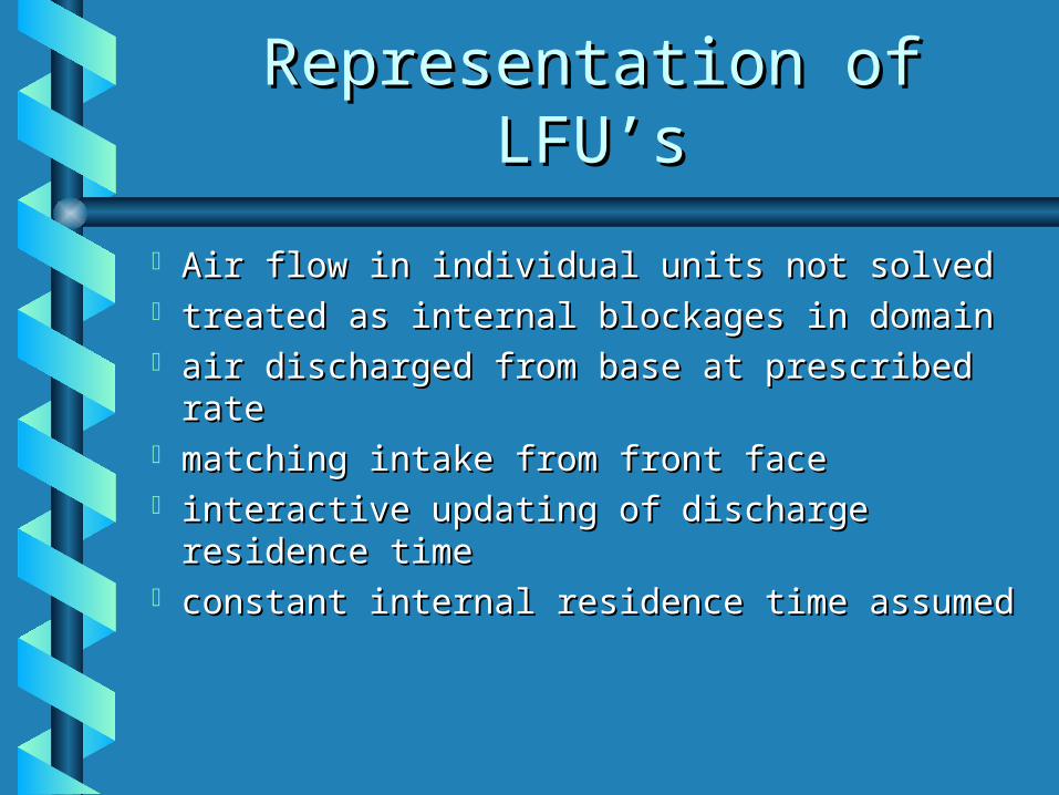
Representation of LFU’sRepresentation of LFU’s
Air flow in individual units not solvedAir flow in individual units not solved treated as internal blockages in domaintreated as internal blockages in domain air discharged from base at prescribed air discharged from base at prescribed
raterate matching intake from front facematching intake from front face interactive updating of discharge interactive updating of discharge
residence timeresidence time constant internal residence time constant internal residence time
assumedassumed
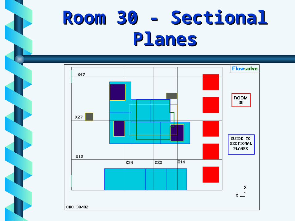
Room 30Room 30
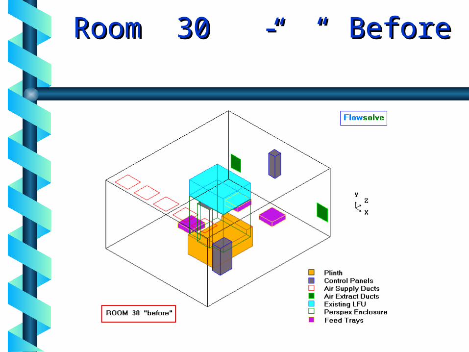
Small room - 4.94 x 5.94 x 2.92 m.Small room - 4.94 x 5.94 x 2.92 m. Used for processing, filling and Used for processing, filling and
packaging of productspackaging of products Contains central plinth with filling-Contains central plinth with filling-
machine enclosure abovemachine enclosure above Conveyor-linked trays outboard of Conveyor-linked trays outboard of
enclosure, for containers & finished enclosure, for containers & finished goods goods
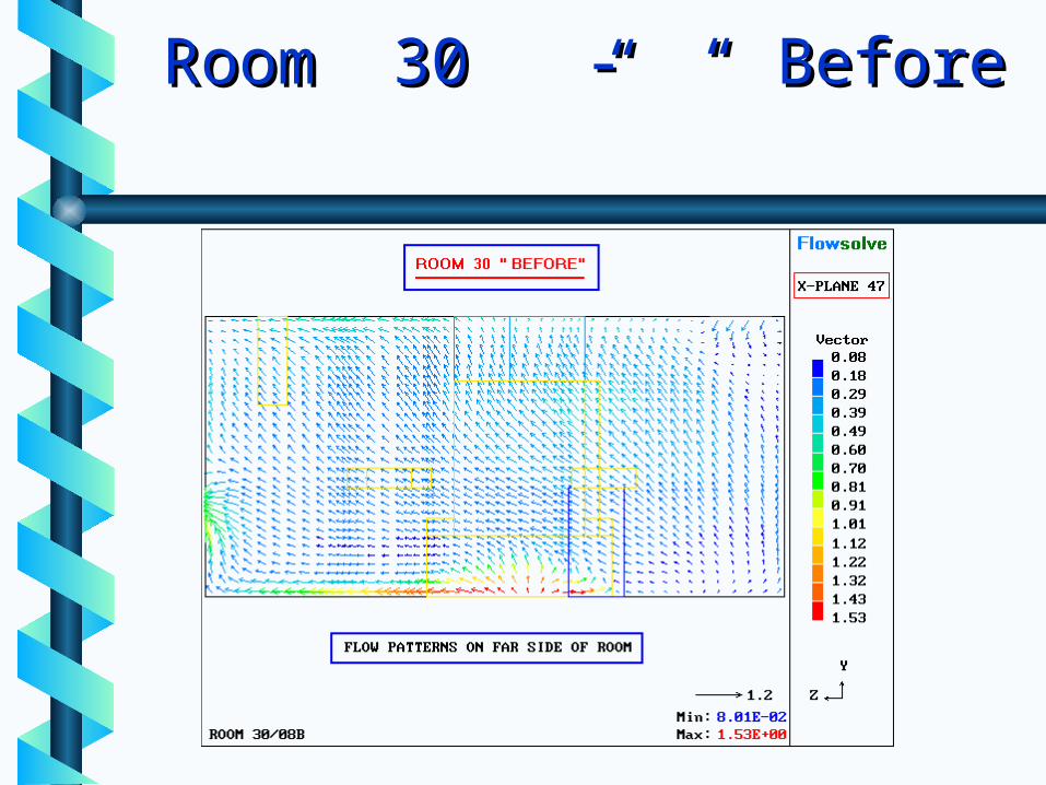
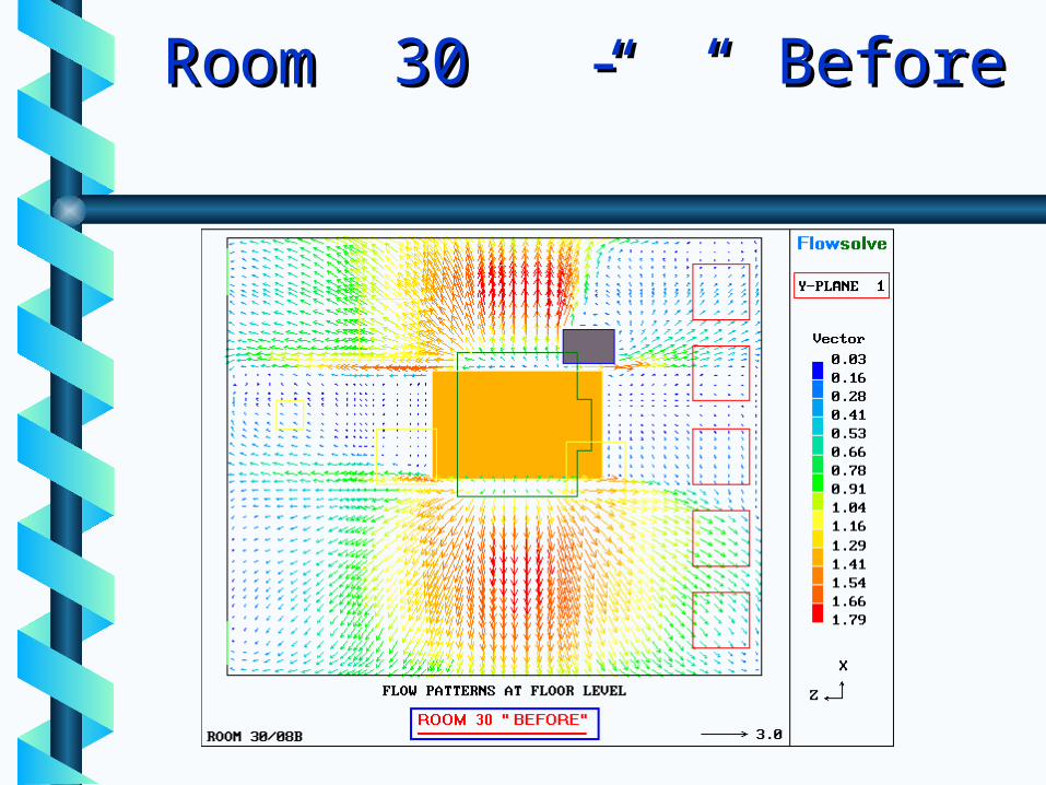
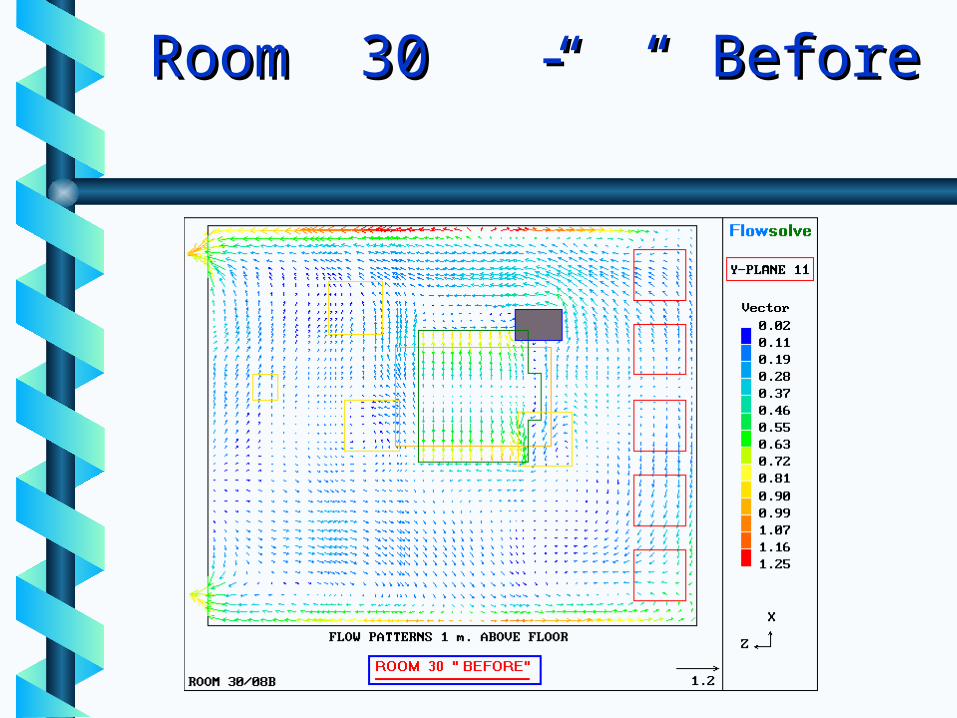
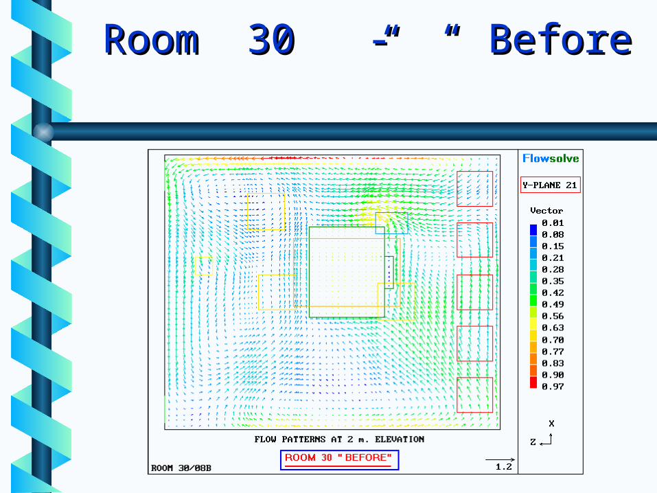
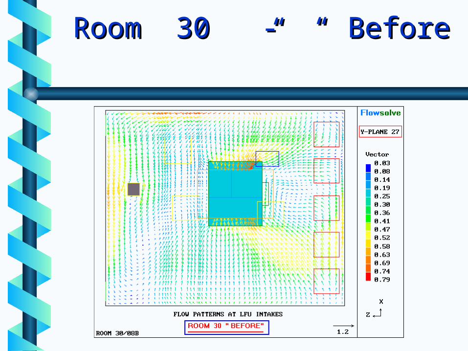
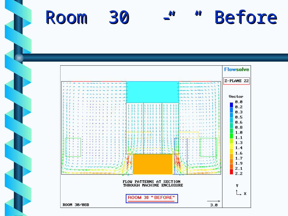
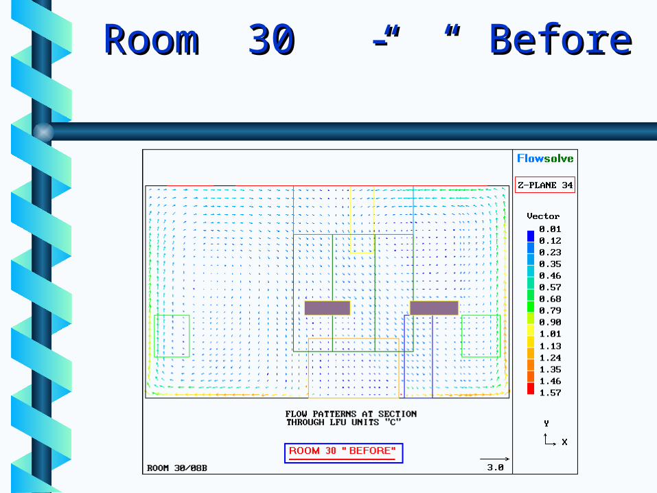
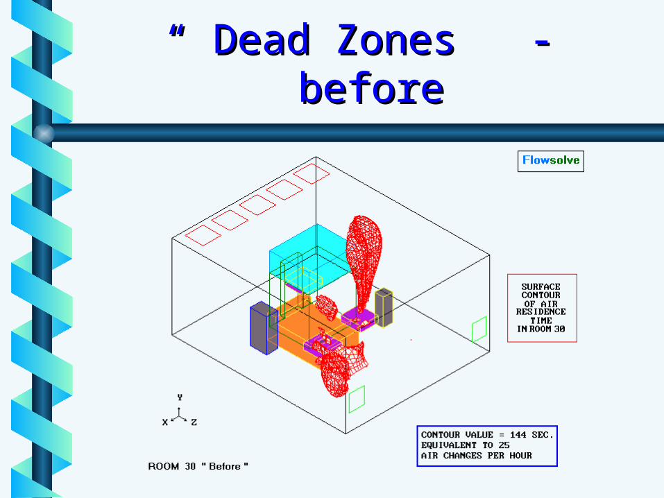
Room 30 - “ Before ”Room 30 - “ Before ”
Room 30 SimulationsRoom 30 Simulations
Steady flow patterns Steady flow patterns “ before ”“ before ”• LFU’s in enclosure onlyLFU’s in enclosure only
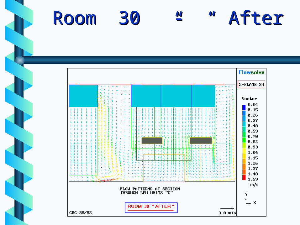
Steady flow patterns Steady flow patterns “ after ”“ after ”• following fitment of 10 new LFU’sfollowing fitment of 10 new LFU’s
75,000 node 3-D model75,000 node 3-D model• Distribution : 50 x 30 x 50Distribution : 50 x 30 x 50
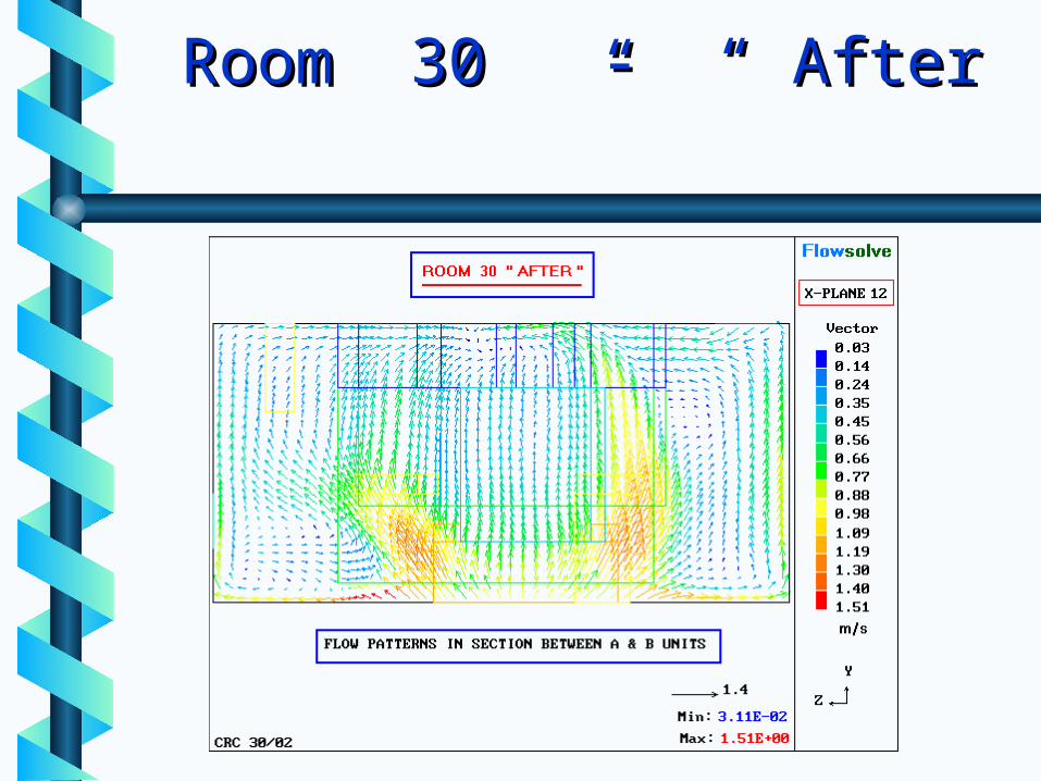
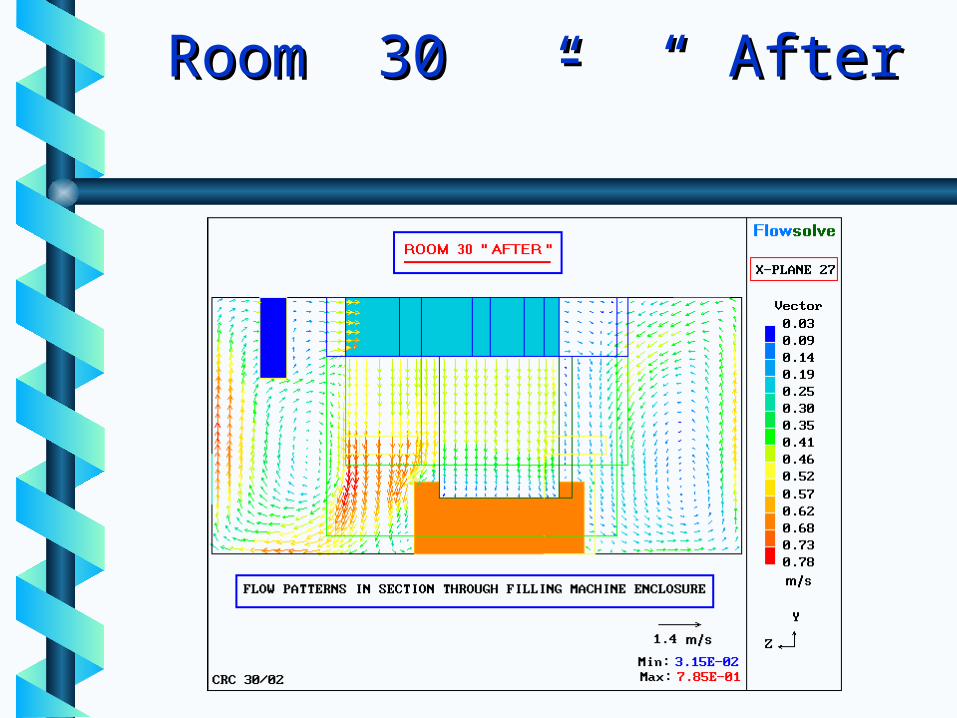
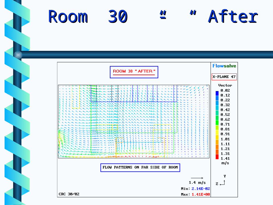
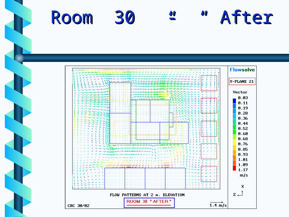
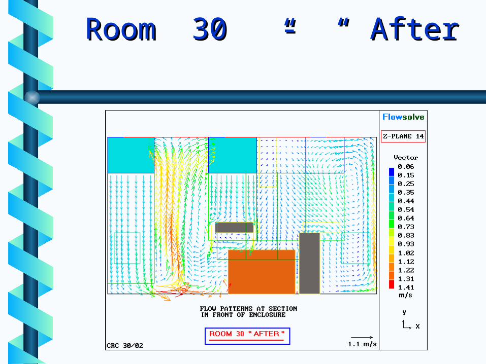
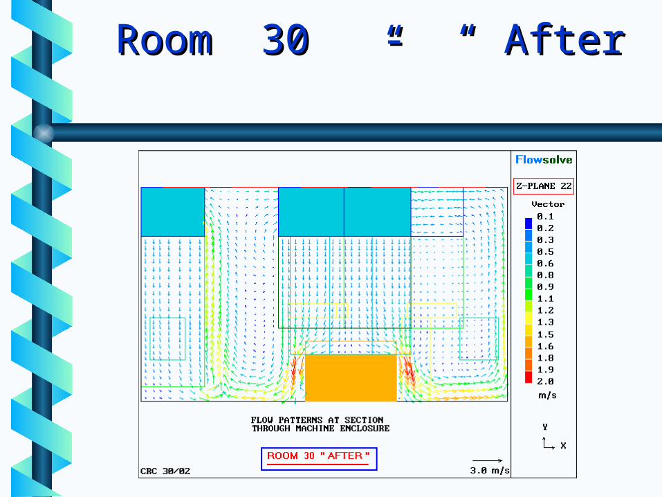
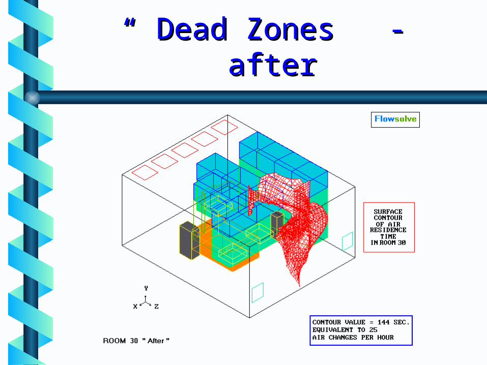
Room 30 - “ After ”Room 30 - “ After ”
Room 30 SimulationsRoom 30 Simulations
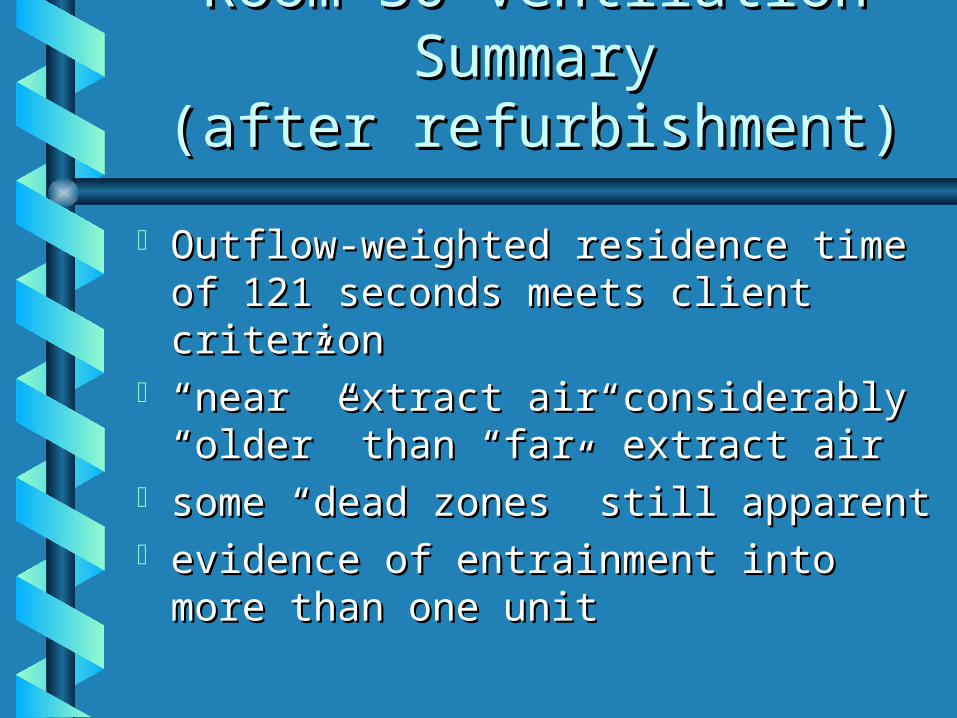
ObjectivesObjectives Check for “dead zones”Check for “dead zones” ensure ventilation criteria metensure ventilation criteria met
CriteriaCriteria 25 Air changes per hour25 Air changes per hour (residence time 144 seconds)(residence time 144 seconds)
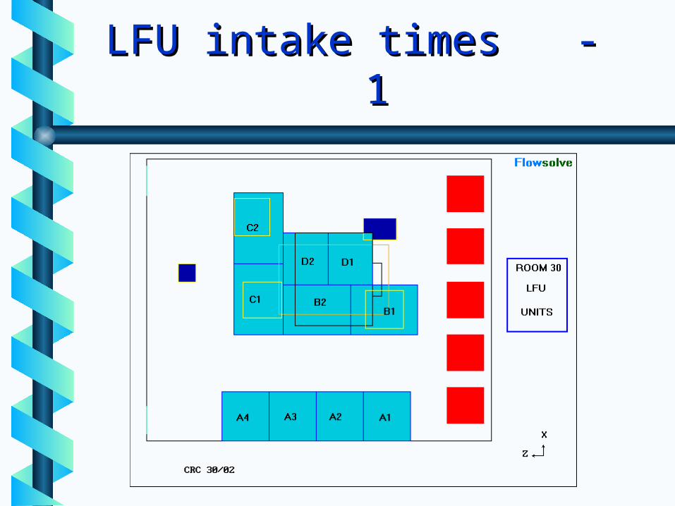
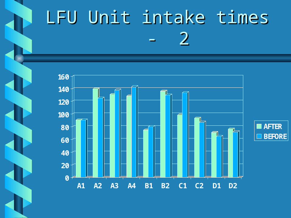
LFU Unit intake times - 2LFU Unit intake times - 2
0
20
40
60
80
100
120
140
160
A1 A2 A3 A4 B1 B2 C1 C2 D1 D2
AFTERBEFORE
LFU Unit intake times - 3LFU Unit intake times - 3
Units D1, D2, B2, C2, A1 receive Units D1, D2, B2, C2, A1 receive considerably fresher air than their considerably fresher air than their neighbours A2-A4, B2 and C1neighbours A2-A4, B2 and C1
Air entering A4 is 2.2 times older Air entering A4 is 2.2 times older than that entering D1than that entering D1
Air leaving A4 exceeds air-change Air leaving A4 exceeds air-change criterion en route to outletcriterion en route to outlet