AIR POLLUTION ENGINEERING MANUAL SECOND EDITION Compiled and Edited bY John A. Donielron AIR POLLUTION CONTROL DISTRICT COUNTY OF LOS ANGELES ENVIRONMENTAL PROTECTION AGENCY Office of Air and Water Programs Office of Air Quality Planning and Standards Research Triangle Park N.C. 27711 May 1973
Transcript
AIR POLLUTION
ENGINEERING MANUAL
S E C O N D E D I T I O N
Compi led a n d E d i t e d
bY John A . D o n i e l r o n
A I R P O L L U T I O N C O N T R O L D I S T R I C T
C O U N T Y O F L O S A N G E L E S
ENVIRONMENTAL PROTECTION AGENCY Office o f Ai r and W a t e r Programs
Office of Air Quality Planning and Standards
Research Triangle P a r k N.C. 27711
M a y 1973
EPA
Text Box
Note: This is a reference cited in AP 42, Compilation of Air Pollutant Emission Factors, Volume I Stationary Point and Area Sources. AP42 is located on the EPA web site at www.epa.gov/ttn/chief/ap42/ The file name refers to the reference number, the AP42 chapter and section. The file name "ref02_c01s02.pdf" would mean the reference is from AP42 chapter 1 section 2. The reference may be from a previous version of the section and no longer cited. The primary source should always be checked.
The AP ser ies of reports is published by the Technical Publications Branch of the Information Services Division of the Office of Administration for the Office of Air and Water Programs, Environmental Protection Agency, to report the results of scientific and engineering studies, and information of general interest in the field of air pollution. Information reported in this series includes coverage of intramural activities and of cooperative studies conducted in conjunction with state and local agencies, research institutes, and industrial organizations. Copies of AP reports a r e available free of charge to Federal employees, current contractors and grantees, andnonprofit organizations - as supplies permit - f rom the Air Pollution Technical Information Center, Environmental Protection Agency, Research Triangle Park, North Carolina 27711 o r from the Superintendent of Documents.
PERCENT LESS THAN GIVEN PARTICLE S I Z E , microns
F igu re 229. P l o t o f p a r t i c l e s i z e o f dust a t the i n l e t and o u t l e t o f a cyc lone and m u l t i p l e cyc lone from t e s t C-537.
CONCRETE-BATCHING P L A N T S Concrete-hatching plants s tore , convey, measure , and discharge the ingredients f o r making concrete to mixing or t ransportat ion equipment. One type is used to charge sand, aggregate, cement, and water to t ransi t -mix t rucks, which mix the hatch en route to the s i te where the concrete i s t o he poured; this operation i s known a s "wet batching. I '
Another type i s used to charge the sand, aggre- gate, and cement to f la t bed t rucks, which t r ans - port the batch to paving machines where water i s added and mixing takes place; this operation is known as "dry hatching. I ' A third type employs the use o f a c e n t r a l m i x d a n t . f r o m whichwet con-
shell c rane , o r bucket elevator t o overhead s torage bins. Cemcnt f rom bottom-discharge hopper t rucks i s conveyed to an elevated s torage silo. Sand and aggregatcs lor a hatch a r e weighed by successive additions f romthe overhead bins to a weigh hopper. Cementis del iveredby a screw conveyor i rom the s i l o t o a separa te weigh hopper. The weighed ag- gregates and cement a r e dropped into a gathering hopper and flow into the receiving hopper to the t ransi t -mixtruck. Atthe s a m e time, the required amount of water is injected into the flowyng s t r e a m of solids. Details and variations of this genera l rxocedure will be discussed la te r .
c r e t e is delivered tothe pouring site in open dump trucks. T h e A i r P o l l u t i o n P r o b l e m
Dust, the a i r contaminant f romwet-concrete-hatch- WET-CONCRETE-BATCHING PLANTS ing, resul ts f r o m t h e m a t e r i a l used. Sbnd and ag-
gregates f o r concrete production come direct ly In a typicalwet-concrete-batching plant, sand and f r o m a rockandgrave lp lan twhere they a r e washed aggregates a r e elevated by belt conveyor or c lam to remove silt and clay-like minerals . They thus
Concrete-Batching P lan t s 335
I 0 to S 5 t o 1 0
1 0 t o 20 2 0 t o 40 40 to SO 50 to 66 66 to 99 99 to 250 250 (60 m e s h )
Bulk density, l b l f t3
a r r i v e a L the batch plant i n a moisr condition and hcncc do not u sua l lyp resen t a dust problcm. Whcn, however , lightweight aggrega te s a r e used , they do pose a problem. T h e s e m a t e r i a l s a r e f o r m e d by thc r ina l expansion of c e r t a i n m i n e r a l s . They leavc the aggregate plant v c r y d r y and c r e a t e cons ide r - ab lcdus twhen handled. The s implcs t way to deal withthis p rob lem i s t o wct each load of aggregate thoroughly bclorc i t is dumped f r o m the de l ive ry t ruck. Attempts to s p r a y the aggrcga tc as it i s heins dumped have had v c r y l imited effect iveness .
If, t hc rc fo re , wet o r d a m p aggrega te i s uscd, p rac t i ca l ly a l l the dust gene ra t ed f r o m conc re t e - batching operat ions or iginates f r o m the cement . P a r t i c l c s i z e dis t r ibut ion and other c h a r a c t e r i s t i c s of the dust v a r y according t o thc g r a d e of cement . A r angc ol 10 to 2 0 pe rcen t by weight of pa r t i c l e s of 5 -mic ron s i z e or less i s typical f o r the va r ious g r a d e s OI cement . Bulk densi ty r anges Irom 50 t o 65 pounds p e r cubic foot of cement . Table 97 shows additional c h a r a c t e r i s t i c s of t h r e e common g r a d e s ol cement.
Specific gravi ty , g / c m 3 a t 8 2 ° F 1 3 . 3 j 3 . 3
Table 97. CHARACTERISTICS O F THREE GRADES OF CEMENT
3 . 3
Cemen t , wt 0: Grade 11 Grade I1 I Grade 111
Distribution, il
Cement d u s t can be emit ted from s e v e r a l points. The receiving hopper , the e l eva to r , and t h e s i l o - a r e the 'points of possible emis s ion f r o m the c e - ment-receiving station. Other points of possible dus t e m i s s i o n a r e the cemen t weigh hopper, the gather ing hopper , and the m i x e r .
A i r P o l l u t i o n C o n t r o l E q u i p m e n !
Cement-rFceiving and s to rage s y s t e m
Atypical cement-receiving and s to rage s y s t e m is shown in F i g u r e 230. The receiving hopper is a t or below ground level. If it i s designed to f i t the canvas d i scha rge tube of the hopper t ruck , l i t t le or no dust is emit ted a t t h i s point. After a b r i e f ini t ia l puff of dust , the hopper f i l ls completely and the cemen t flows f r o m the t r u c k without any f r e e fall. Cement e l eva to r s are ei ther the ve r t i ca l - s c r e w type or the enclosed-bucket type. Neither e m i t s any dus t if in good condition. The cement s i l o m u s t b e vented t o allow the a i r displaced by the c e m e n t t o escapc. Unless th i s vent is f i l tered, a significant amount of dus t e scapes .
F i g u r e 230 shows one type oI f i l t e r . It cons i s t s of a c lothtube with a s t a c k and wea the rcap fo r p ro - tection. The pulley a r r a n g e m e n t allows it to be shaken f r o m the ground s o that the accumulated l a y e r of dus t on the inside of the cloth tube can be per iodical ly removed. The cloth 's a r e a should be sufficient t o provide a fi l tering velocity of 3 f p m , based upon the displaced air r a t e .
Many concrete batch plants now rece ive cement pneumatically f r o m t rucks equipped with c o m p r e s - so r s and pneumatic de l ive ry tubes . I n t h e s e plants, a s ing le f i l t e r edven t used f o r the g rav i ty fi l l ing of cemen t has proved inadequate, and o the r methods of control a r e required. the volume of conveying a i r i s approximately 350 c fm d u r i n g m o s t o f t h e loading cycle and i n c r e a s e s t o 700 c f m a t the end of the cycle.
In this pneumatic del ivery,
T o c o n t r o l t h i s v o l u m e of a i r , i t is b e s t t o instal l a s m a l l conventional cotton sa t een baghouse with a f i l ter ing a r e a of 3 f p m (approximately200 squa re feet of cloth a r e a ) t o vent the cement s i lo . The baghouse should be equipped with a blower to re- l ieve the p r e s s u r e built up within the s i lo . A mechanical shaking m e c h a n i s m a l s o should be provided t o p r e v e n t cement f r o m blinding the fil- t e r cloth of the baghouse.
Another less expensive type of control device is tomount a bankof approximately four s imple f i l - t e r e d vents a top the s i lo . The fi l tering a r e a should not exceed 7 f p m , giving a n a r e a of ap - proximately 100 s q u a r e f e e t f o r the 700 c fm of a i r encountered a t the end of the cycle. The f i l t e r d e s i g n m u s t include a shaking mechan i sm t o p r e - ventblinding of the f i l t e r cloth. The m a j o r d i s -
336 MECHANICAL EQUIPMENT
Figure 230. Cement-receiving and storage system.
advantage of using a bank of several simple filter vents a s justdescribedis the possibility of pres - surehuild-upwithinthe silo. If, fo r some reason, the filter should become blinded, there is danger of rupturingthe silo. Therefore, proper mainte- nance and regular inspection of the filter a r e necessary.
Where baghouses a r e used to control other larger cement dust sources such a s those existing in a dry-concrete-batching plant or in a central mix plant, then the cement silo can easily be vented to the same baghouse.
Cement weigh hopper
The cement weigh hopper may be a compartment inthe aggregate weigh hopper or it may be a sep- arate weigh hopper. Cement is usually delivered from the silo to the weigh hopper by an enclosed screw conveyor. To permit accurate weighing, a flexible connectionbetween the screw conveyor and weigh hopper is necessary. A canvas shroud i s usually used, and i f properly installed and main- tained, prevents dust emissions a t this point. The
weigh hopper is filled at a fairly rapid rate, and the displaced a i r entrains a significant amount of dust. This dust may be controlled by venting the displacedair backto the cement silo or by install- ing afi l teredvent onthe weigh hopper a s described for cement silos.
The vent should be of adequate size to provide a filtering velocity of about 3 fpm, based upon the cement's volumetric filling rate. For example, ifaweighhopperisfilledattherateof 1,500 pounds in 1/2minute, andthedensityof cementis 94pounds per cuhicfoot, thedisplacedair rate equals 1-, 5 0 0 1 (94)(0.5), o r 32cfm. Therequiredclothareawould then be 3213 or 10.7 square feet.
Gathering hoppers
The dropping of a batch from the weigh hopper to the mixer can cause cement dust emissions f rom severalpoints. In theloading of transit-mix trucks, a gathering hopper is usually used to control the flow of the materials. Dust can be emitted f rom the gathering hopper, the truck's receiving hopper, andthe mixer. The design and location of the gath- ering hopper can do much to minimize dust emis- sions. Thehopper should make a good fit with the truck receiving hopper, and its vertical position shouldheadjustahle. Figure 231 illustrates a de- signthat has been used successfully in minimizing dust emissions. Compressed-air cylinders raise and lower the gathering hopper to accommodate trucks of varying heights. A steel plate with a foam rubber backing is attached to the bottom of the gathering hopper and is lowered until it res t s onthe top of the truck's receiving hopper. Water for the mix i s introduced through a jacket around the discharge spout of the gathering hopper and forms a dust-reducing curtain.
Discharge of the ce6en t hbpper into the center of the aggregate stream, and choke feed between the weigh hopper and the gathering hopper suppress dust emissions from the top of the gathering hopper.
DRY-CONCRETE-BATCHING PLANTS
Dry-concrete-batchingplants areusedin road con- struction work. Because of advances in freeway constructionin recent years, plants such a s these a r e located in metropolitan a reas , often in res i - dential zones. The plants a r e portable, that is, theymustbedesignedto be moved easily f rom one location to another. This is, of course, a factor in the designof the air pollution control equipment.
Concrete -Bat ching Plants 337
M E T A L PLATE
A " ~ A\ FOAM RUBBER
I IWI Figure.231. An adjustable ga ther ing hopper.
T h e A i r P o l l u t i o n P r o b l e m
Dryhatching poses amuchmore difficult dust con- trol problem than wet hatching does. Since most plants that do dry batching also do wet batching, the gathering hopper must be set high enough to accommodate transit-mix trucks. Since the re - ceivinghopper of most transit-mix trucks i s sev- eralfeet higher than the top of the flat-bed trucks used in dry hatching, there is a long f ree fall of material when a dry batch is dropped. This pro- duces a considerable amount of dust, sufficient to violatemost codes that have an opacity limitation applicable to this type of operation.
From an a i r pollution standpoint, the dust to be collected has characteristics similar t o those of the cement dust already discussed ior wet-con- crete-hatching plants. In d ry hatching, however, volumes of dust created a r e considerably greater because: (1) The amount of concrete hatched is large, (2) no water is used, and ( 3 ) the batches a r e dropped rapidly into the waiting trucks to con- serve time.
H o o d i n g a n d V e n t i l o t i o n R e q u i r e m e n t s
A local exhaust system with an efficient dust col- lector is required to control a dry batching plant adequately. This is a difficult operation to hood
without interfering with the truck's movement o r the batch operator's view. The truck bed i s usually divided into several compartments, a batch being dropped into each compartment. This necessitates repeated spotting of each truck under the direction of the batch operator; hence he must be able to see the truck at the drop point. A canopy-type hood just large enough to cover one compartment a t a time provides effective dust pickup and affords adequate visibility. Figure 2 3 2 shows a closeup view of a hood of this type. The sides a r e made of sheets of heavy rubber to permit contact with the truckbedwithout damage. This hood is mounted on rails to permit it to be withdrawn to allow wet batching into transit-mix trucks.
The exhaust volume required to collect the dust varies with the shape and position of the hoods. With reasonablygoodhooding, the required volume i s approximately 6 ,000 to 7 ,000 cfm.
A i r P o l l u t i o n C o n t r o l E q u i p m e n t
Abaghouse is the most suitable type of dust collec- tor fo r this service. Scrubbers have been used,but they have been plagued withdifficulties such a s low collection efficiency, plugged spray nozzles, cor- rosion, and waste-water disposal problems. A baghouse for this service should have a filtering velocity of 3 fpm. It may be of the intermittent shaking type, since sufficient opportunities for stopping the exhauster for bag shaking a r e usually available. Figure 2 3 3 is an overall view of a typ- ically controlled d r y batching plant with the bag- house shown on the left. The drop area tunnel is enclosed on the sides and partially on the ends.
Dust created by truck movement
Inmany instances thegreatest source of dust f rom the operation of a concrete batch plant i s that cre- ated by the trucks entering and leaving the plant area. If possible, the yardandaccess roads should be paved or oiled, or i f this is not feasible, they should be watered frequently enough to suppress the dust.
CENTRAL MIX PLANTS
The centralmixplant, a s shownin Figure 2 3 4 , is being used more and more extensivelyby the con- crete industryinthe Los Angeles area. In a cen- t r a l batch operation, concrete is mixed in a sta- tionarymixer, discharged into a dump truck, and transportedinawet mixed condition to the pour- ing site.
The handling of aggregate and cement at these plants is similar tothat atthe other concrete batch plants.
338 MECHANICAL EQUIPMENT
c
Figure 232. Closeup O f hood fo r c o n t r o l l i n g dry batching: ( l e f t ) Hood i n place, ( r i g h t ) hood in re t rac ted p o s i t i o n (Graham Bros.. E l Monte. Ca l i f . ) .
Figure 234. Overal l view of a c e n t r a l mix concrete- batching p l a n t c o n t r o l l e d by a baghouse ( G r i f f i t h Co., Los Angeles, Ca l i f . ) .
Figure 233. Overal l view of w e t - and dry-concrete- batching p l a n t and baghouse located a t a C a l i f o r n i a Freeway p r o j e c t (by F. Atkinson Co., Long Beach, Ca I i f . ).
T h e Air P o l l u t i o n P r o b l e m
F r o m an air pollution control standpoint, this type of .operation is preferable to d ry batching. The dust is more easilycaptured a t the batch plant, and further, there i snogenera t ion of dust at the pour- ing site. The operation i s also preferable to wet hatching because designing control equipment for a s ta t ionarymixer i s eas ie r thani t is fo r a t ransi t -
Sand, aggregate, cement, and water a r e all weighed or metered as i n a wet-c.oncrete-batching plant and discharged through an enclosed system into the mixer. mix truck-loading area .
Cement-Handling Equipment 339
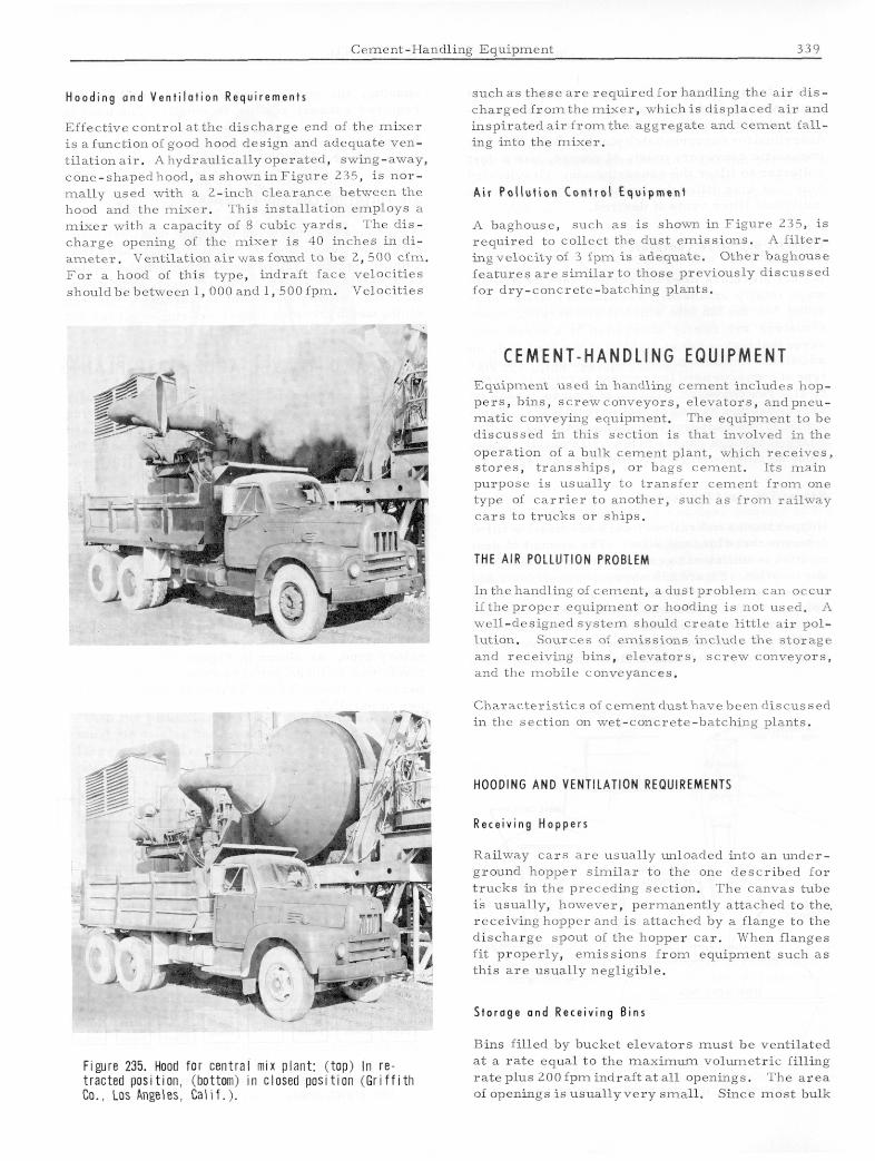
H o o d i n g a n d V e n t i l a t i o n Requi rements
Effective control a t the discharge end of the mixer i s afunct ionof good hood design and adequate ven- t i l a t iona i r . Ahydraul ical lyoperated, swing-away, cone-shapedhood, a s showninFigure 235, is n o r - mal ly used with a 2-inch c learance between the hood and the mixer . This installation employs a m i x e r with a capacity of 8 cubic yards . The d i s - charge opening of the m i x e r i s 40 inches i n di- amrter. For a hood of this type, indraft f a c e velocit ies shouldhebetween 1,000 and 1, 500 fpm. Velocities
Vent i la t iona i rwas found t o h e 2. 500 cfm.
Figure 235. Hood fo r cen t ra l mix plant: ( top) In r e - t rac ted pos i t ion . (bottom) i n closed p o s i t i o n ( G r i f f i t h Co.. Los Rngeles. Calif.).
such as these are required f o r handling the a i r dis- charged f r o m the rnixcr, which is displaced air and insp i ra teda i r f r o m t h e aggregate and cement fa l l - ing into the mixer .
A i r P o l l u t i o n C o n t r o l E q u i p m e n t
A baghouse, such a s is shown in F igure 235, i s required t o collect the dust emissions. A f i l t e r - ingvelocity of 3 fpm is adequate. Other baghouse fea tures a r e s imi la r to those previously discussed for dry-concrete-batching plants.
C E M E N T - H A N D L I N G E Q U I P M E N T Equipment used in handling cement includes hop- p e r s , bins, screwconveyors , e levators , andpneu- mat ic conveying equipment. The equipment t o bc discussed in this section i s that involved in the operation of a bulk cement plant, which rece ives , s tores , t ranssh ips , or bags cemcnt. I ts main purpose i s usually to t ransfer cemcnt f r o m one type of c a r r i e r t o another, such a s irom rai lway cars to t rucks o r ships.
THE AIR POLLUTION PROBLEM
In the handling of cement , a dust problem can occur i f the proper equipment 01. hooding i s not used. A well-designed s y s t e m should c r e a t c l i t t le a i r pol- lution. Sources of emissions includc the s torage and receiving bins, e levators , s c rew conveyors, and the mobile conveyances.
Charac te r i s t ics of cement dus thave been discussed in the section on wet-concrete-batching plants.
HOODING AND VENTILATION REQUIREMENTS
Rece iv ing Hoppers
Railway c a r s a r c usually unloaded into an under- ground hopper s i m i l a r t o the one descr ibed for t rucks in the preceding section. The canvas tube is usually, however, permanently attached to the. receiving hopper and i s attached by a flange t o the discharge spout of the hopper c a r . When flanges f i t properly, emissions from equipment such a s th i s a r e usually negligible.
Storage and Receiving Bins
Bins fi l led by bucket e levators m u s t be ventilated at a r a t e equal t o the maximum volumetr ic filling r a t e plus 2 0 0 f p m i n d r a f t a t a l l openings. The a r e a of openings is usua l lyvery small . Since m o s t bulk
340 MECHANICAL EQUIPMENT
plants have a number of bins, a regular exhaust systemwithadust collectorprovides a more prac- tical solutionthanthe silofiltervents do that were describedfor concretebatcbplants. Bins filled by pneumatic conveyors must, of course, use a dust collector to fi l ter the conveying air . Gravity-fed bins and bins filled by bucket elevators can use individual f i l ter vents if desired.
E l e v a t o r s and Screw C o n v e y o r s
Bucket elevators used, for cement service a re al- ways totally enclosed. Ventilation must be pro- vided for the bin into which it discharges. Since elevators a re nearly always fed by a screw con- veyor that makes a dust-tight fit at the feed end, no additional ventilation i s usually required. Another typeof conveyorusedfor cement service is a ver- tical screwconveyor. These, of course, cause no dust emissionsaslongastheyhavenoleaks. Hori- zontalscrew conveyors a re frequently fed or dis- charged through canvas tubes or shrouds. These must be checked regularly for tears or leaks.
H o p p e r T r u c k a n d Car L o a d i n g
Hopper trucks and railroad cars a re usually filled fromoverheadbins and silos. The amount of dust emitted is sufficient to cause a nuisance in almost anylocation. Figure 236 shows a type of hood and loading spout that permits these emissions to be collectedwithaminimumamount of air . The ven- tilation rate i s the same as for bins, the displaced air rate plus 200 fpm through all openings. If the hoodis designed to make a close fit with the hatch
)ilR CONVHOR
CEMENT HOPPER TRUCK
I u Figure 236. Hood f o r t ruck- load ing s ta t ion .
opening, the open spaces a re very small and the required exhaust volume i s small. The hood is attachedto the telescoping cement discharge spout in such a way that it can be raised and lowered when hopper trucks a re changed.
AIR POLLUTION CONTROL EQUIPMENT
Abaghousehas beenfound to be the most satisfac- tory dust collector for handling the ventilation points described. Al l sources arenormally ducted to a single baghouse. Cotton sateen cloth with a filtering velocity of 3 fpm is adequate. Dacron cloth, whichprovides longer wearing qualities but is more expensive, can also be used.
ROCK A N D G R A V E L A G G R E G A T E P L A N T S Rock and gravel plants supply sand and variously sized aggregates for the construction and paving industries. The sources of most aggregates used in Los Angeles County a re the gravel beds in the San Fernando and San Gabriel valleys. The pro- cessing of the gravel consists of screening out the usable sizes and crushing the oversize into various size ranges. Asimplified flow diagram for a typ- icalplant is shownin Figure 237. Incoming mate- r ia l i s routed through a jaw crusher, which is set to act upon rocks larger than about 6 inches and to pass smaller sizes. The product from this crusher is screened into sizes smaller and larger than 1-1/2 to 2 inches, the undersize going to a screening plant, and the oversize to the crushing plant. Thesenextcrushers a re of the cone or gy- ratory type, as shown in Figure 238. In a large plant, two or three primary crushers a re used in parallel followed by two to five secondary crush- e r s in parallel.
Figure 237. S i m p l i f i e d f l o w diagram o f a t y p i c a l rock gravel p lant.