1 AIR TO WATER HEAT PUMP SYSTEM HOT WATER CYLINDER INDIRECT HEATING METHOD CLOSED OUTLET (UNVENTED) INSTALLATION AND SERVICE MANUAL 36006030_Issue_H HWS-1501CSHM3-UK HWS-2101CSHM3-UK HWS-3001CSHM3-UK
Transcript
1
AIR TO WATER HEAT PUMP SYSTEMHOT WATER CYLINDER
INDIRECT HEATING METHODCLOSED OUTLET (UNVENTED)
INSTALLATION AND SERVICE MANUAL
36006030_Issue_H
HWS-1501CSHM3-UKHWS-2101CSHM3-UKHWS-3001CSHM3-UK
2
INSTALLATION AND SERVICING INSTRUCTIONS, FOR AIR TO WATER HEAT PUMP SYSTEM WATER CYLINDER. PLEASE LEAVE THIS MANUAL WITH THE
UNIT FOR FUTURE REFERENCE.
CONTENTS SECTION CONTENT PAGE
1 INTRODUCTION . . . . . . . 2
2 GENERAL REQUIREMENTS . . . . . . 3
3 INSTALLATION - GENERAL . . . . . . 4
4 INSTALLATION – INDIRECT UNITS . . . . . 9
5 COMMISSIONING . . . . . . . 9
6 MAINTENANCE . . . . . . . 10
7 FAULT FINDING AND SERVICING . . . . . 11
8 USER INSTRUCTIONS . . . . . . 13
9 GUARANTEE . . . . . . . . 14
1.0 INTRODUCTION
IMPORTANT: THIS APPLIANCE IS NOT INTENDED FOR THE USE BY PERSONS (INCLUDING CHILDREN) WITH REDUCED PHYSICAL, SENSORY OR MENTAL CAPABILI-TIES, OR LACK OF KNOWLEDGE AND EXPE-RIENCE, UNLESS THEY HAVE BEEN GIVEN SUPERVISION OR INSTRUCTION CONCERN-ING THE USE OF THE APPLIANCE BY A PER-SON RESPONSIBLE FOR THEIR SAFETY.
This unit, for use with the ESTIA air to water heat pump system, is a purpose designed unvented water cylinder. The unit has a stainless steel inner vessel which ensures an excellent standard of corrosion re-sistance. The outer casing is a combination of resilient thermoplastic mouldings and plastic coated corrosion proofed steel sheet. NOTE: Prior to installation the unit should be stored
in an upright position in an area free from excessive damp or humidity.
The unit is supplied complete with all the necessary safety and control devices needed to allow connec-tion to the cold water mains. All these components are pre-adjusted.
This appliance complies with the requirements of the CE marking directive and is KIWA approved to show compliance with Building Regulations (Section G3) and UK Water Regulations.
The following instructions are offered as a guide to installation which must be carried out by a competent plumbing and electrical installer in accordance with Building Regulation G3, The Building Standards (Scotland) Regulations Section 4 standard 4.9, or The Building Regulations (Northern Ireland) Part P Section P5.
IMPORTANT: PLEASE READ ALL THESE INSTRUCTIONS BEFORE COMMENCING INSTALLATION
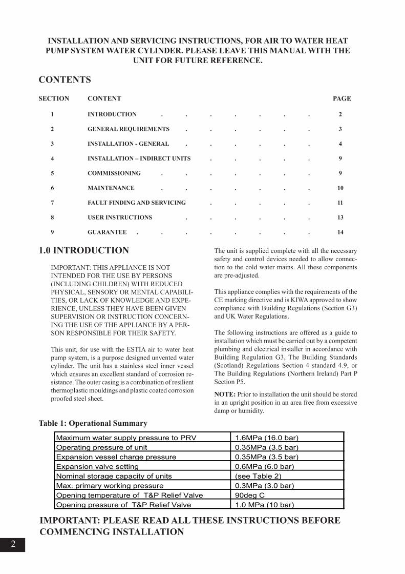
Maximum water supply pressure to PRV 1.6MPa (16.0 bar)Operating pressure of unit 0.35MPa (3.5 bar)Expansion vessel charge pressure 0.35MPa (3.5 bar)Expansion valve setting 0.6MPa (6.0 bar)Nominal storage capacity of units (see Table 2)Max. primary working pressure 0.3MPa (3.0 bar)Opening temperature of T&P Relief Valve 90deg COpening pressure of T&P Relief Valve 1.0 MPa (10 bar)
Table 1: Operational Summary
3
2.0 GENERAL REQUIREMENTS
2.1 COMPONENTS SUPPLIED1. Unvented water cylinder incorporating cylinder heater and thermal controls 2. Factory fitted Temperature/Pressure Relief Valve 3. T&P Valve insulation and housing.4. Cold Water Combination Valve. 5. Expansion Vessel and mounting bracket. 6. Tundish.7. Compression nuts and olives8. Cylinder heater key spanner
2.2 SITING THE UNITThe unit must be installed vertically. Although loca-tion is not critical, the following points should be considered:• The unit should be sited to ensure minimum dead leg distances, particularly to the point of most frequent use.• Avoid siting where extreme cold temperatures will be experienced. All exposed pipework should be insulated.• The discharge pipework from the safety valves must have minimum fall of 1:200 from the unit and terminate in a safe and visible position.• Access to associated controls and cylinder heater should be possible to allow for periodic servicing and maintenance.• Ensure that the base chosen for the unit is level and capable of permanently supporting the weight when full of water (see Table 2).
2.3 WATER SUPPLY Bear in mind that the mains water supply to the property will be supplying both the hot and cold wa-ter requirements simultaneously. It is recommended that the maximum water demand is assessed and the water supply checked to ensure this demand can be satisfactorily met.NOTE: A high mains water pressure will not always guarantee high flow rates.Wherever possible the mains supply pipe should be 22mm. We suggest the minimum supply requirements should be 0.15MPa (1.5 bar) pressure and 20 litres per minute flowrate. However, at these values outlet flowrates may be poor if several outlets are used si-multaneously. The higher the available pressure and flowrate the better the system performance.The unit has an operating pressure of 0.35MPa (3.5
bar) that is controlled by the Cold Water Combination Valve. The Cold Water Combination Valve can be connected to a maximum mains pressure of 1.6MPa (16 bar).
2.4 OUTLET/TERMINAL FITTINGS (TAPS, ETC.)The unit can be used with most types of terminal fit-tings. It is advantageous in many mixer showers to have balanced hot and cold water supplies. In these instances a balanced pressure cold water connection should be placed between the Cold Water Combination Valve and the water cylinder. Outlets situated higher than the unit will give outlet pressures lower than that at the cylinder, a 10m height difference will result in a 0.1MPa (1 bar) pressure reduction at the outlet.
2.5 LIMITATIONSThe unvented water cylinder should not be used in association with any of the following:• Ascending spray type bidets or any other class 1 back syphonage risk requiring that a type A air gap be employed.• Situations where maintenance is likely to be neglected or safety devices tampered with.• Water supplies that have either inadequate pres-sure or where the supply may be intermittent.• Situations where it is not possible to safely pipe away any discharge from the safety valves.• In areas where the water consistently contains a high proportion of solids, e.g. suspended matter that could block the strainer, unless adequate filtration can be ensured.
Table 3: Standing heat losses Table 2: Unit weights
Based on an ambient air temperature of 20oC and a stored water temperature of 65oC
All pipe fittings are made via 22mm compression fittings directly to the unit. The fittings are threaded 3/4”BSP male parallel should threaded pipe connec-tions be required.
3.2 COLD FEEDA 22mm cold water supply is recommended however, if a 15mm (1/2”) supply exists which provides suf-ficient flow this may be used (although more flow noise may be experienced). A stopcock or servicing valve should be incorporated into the cold water supply to enable the unit and its associated controls to be isolated and serviced.
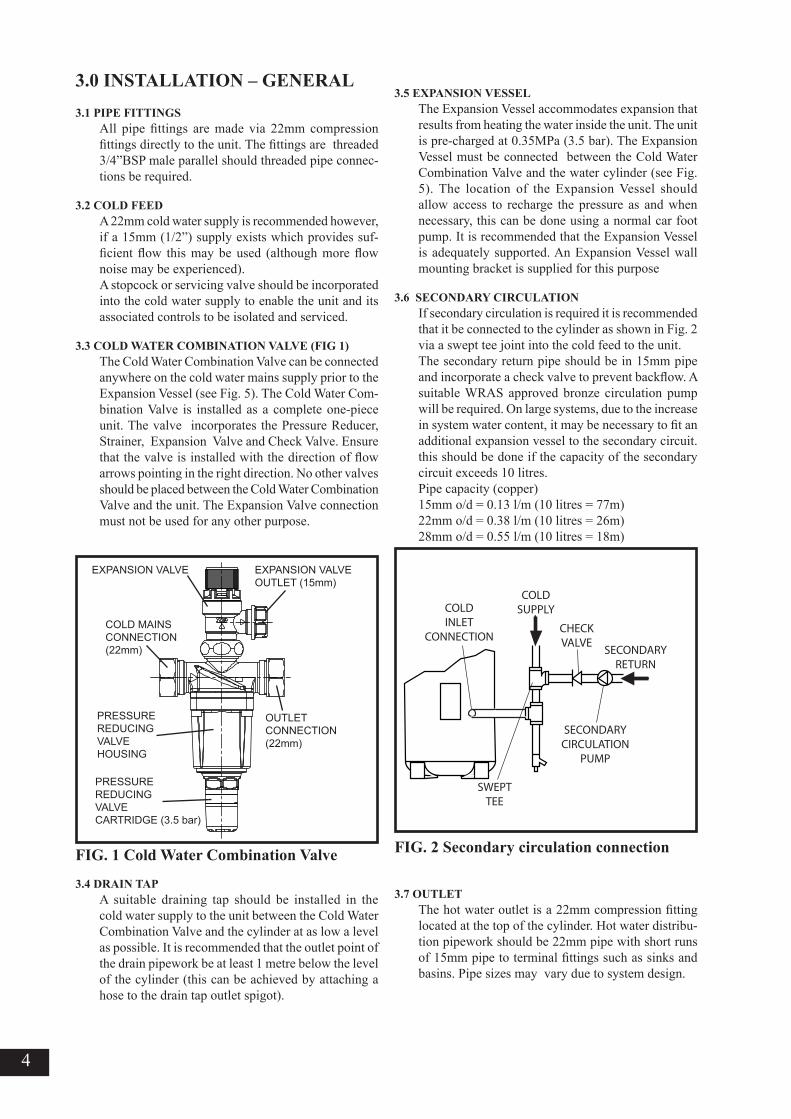
3.3 COLD WATER COMBINATION VALVE (FIG 1)The Cold Water Combination Valve can be connected anywhere on the cold water mains supply prior to the Expansion Vessel (see Fig. 5). The Cold Water Com-bination Valve is installed as a complete one-piece unit. The valve incorporates the Pressure Reducer, Strainer, Expansion Valve and Check Valve. Ensure that the valve is installed with the direction of flow arrows pointing in the right direction. No other valves should be placed between the Cold Water Combination Valve and the unit. The Expansion Valve connection must not be used for any other purpose.
3.4 DRAIN TAPA suitable draining tap should be installed in the cold water supply to the unit between the Cold Water Combination Valve and the cylinder at as low a level as possible. It is recommended that the outlet point of the drain pipework be at least 1 metre below the level of the cylinder (this can be achieved by attaching a hose to the drain tap outlet spigot).
3.5 EXPANSION VESSELThe Expansion Vessel accommodates expansion that results from heating the water inside the unit. The unit is pre-charged at 0.35MPa (3.5 bar). The Expansion Vessel must be connected between the Cold Water Combination Valve and the water cylinder (see Fig. 5). The location of the Expansion Vessel should allow access to recharge the pressure as and when necessary, this can be done using a normal car foot pump. It is recommended that the Expansion Vessel is adequately supported. An Expansion Vessel wall mounting bracket is supplied for this purpose
3.6 SECONDARY CIRCULATIONIf secondary circulation is required it is recommended that it be connected to the cylinder as shown in Fig. 2 via a swept tee joint into the cold feed to the unit. The secondary return pipe should be in 15mm pipe and incorporate a check valve to prevent backflow. A suitable WRAS approved bronze circulation pump will be required. On large systems, due to the increase in system water content, it may be necessary to fit an additional expansion vessel to the secondary circuit. this should be done if the capacity of the secondary circuit exceeds 10 litres.Pipe capacity (copper)15mm o/d = 0.13 l/m (10 litres = 77m)22mm o/d = 0.38 l/m (10 litres = 26m)28mm o/d = 0.55 l/m (10 litres = 18m)
3.7 OUTLETThe hot water outlet is a 22mm compression fitting located at the top of the cylinder. Hot water distribu-tion pipework should be 22mm pipe with short runs of 15mm pipe to terminal fittings such as sinks and basins. Pipe sizes may vary due to system design.
EXPANSION VALVE
COLD MAINSCONNECTION(22mm)
EXPANSION VALVEOUTLET (15mm)
OUTLET CONNECTION(22mm)
PRESSUREREDUCING VALVEHOUSING
PRESSUREREDUCING VALVECARTRIDGE (3.5 bar)
COLDINLET
CONNECTION
COLDSUPPLY
CHECKVALVE
SECONDARYRETURN
SECONDARYCIRCULATION
PUMP
SWEPTTEE
5
FIG. 3 General Dimensions and Performance
NOMINAL CAPACITY (litres)
A (mm)
B (mm)
C (mm)
D (mm)
SURFACEAREA (sq.m)
HOTWATEROUTPUTAT60ºC (litres)
MIXED HOTWATEROUTPUTAT40ºC (litres)
HEATLOSS(kWh/24h)
HEATING TIME15ºC TO 60ºC - USING ELECTRICCYLINDER HEATERONLY(mins)
CAPACITYHEATED USING ELECTRICCYLINDER HEATERONLY(litres)
150 210 300
315 315 315
354 354 354
800 1184 1474
1090 1474 2040
0.65 0.79 0.79
102 163 254
243 329.5 476
1.45 1.91 2.52
123 188 262
102 163 254
6
Worked example of discharge pipe sizing
The example below is for a G1/2 temperature relief valve with a discharge pipe (D2) having 4 No. elbows and length of 7m from the tundish to the point of dis-charge.
From Table 4:Maximum resistance allowed for a straight length of 22mm copper discharge pipe (D2) from a G1/2 tempera-ture relief valve is 9.0m.Subtract the resistance for 4 No. 22mm elbows at 0.8m each = 3.2m
Therefore the permitted length equates to: 5.8m
5.8m is less than the actual length of 7m therefore calcu-late the next largest size.
Maximum resistance allowed for a straight length of 28mm pipe (D2) from a G1/2 temperature relief valves equates to 18m.Subtract the resistance of 4 No. 28mm elbows at 1.0m each = 4.0m
Therefore the maximum permitted length equates to: 14m
As the actual length is 7m, a 28mm (D2) copper pipe will be satisfactory.
3.8 DISCHARGE PIPEWORK It is a requirement of Building Regulation G3 that any discharge from an unvented system is conveyed to where it is visible, but will not cause danger to persons in or about the building. The tundish and discharge pipes should be fitted in accordance with the require-ments and guidance notes of Building Regulation G3. The G3 Requirements and Guidance section 3.9 are reproduced in the following sections. Information Sheet No. 33 available from the British Board of Agrement gives further advice on discharge pipe installation. For discharge pipe arrangements not covered by G3 Guidance or BBA Info Sheet No.33 advice should be sought from either your local Build-ing Control Officer.
G3 REQUIREMENT“...there shall be precautions...to ensure that the hot water discharged from safety devices is safely conveyed to where it is visible but will not cause danger to persons in or about the building.”
G3 GUIDANCE SECTION 3.9The discharge pipe (D1) from the vessel up to and including the tundish is generally supplied by the manufacturer of the hot water storage system. Where otherwise, the installation should include the discharge pipe(s) (D1) from the safety device(s). In either case the tundish should be vertical, located in the same space as the unvented hot water storage system and be fitted as close as possible and within 500mm of the safety device e.g. the temperature relief valve.The discharge pipe (D2) from the tundish should terminate in a safe place where there is no risk to persons in the vicinity of the discharge, preferably be of metal and:a. be at least one pipe size larger than the nominal outlet size of the safety device unless its total equiva-lent hydraulic resistance exceeds that of a straight pipe 9m long i.e. discharge pipes between 9m and 18m equivalent resistance length should be at least two sizes larger than the nominal outlet size of the safety device, between 18 and 27m at least 3 sizes larger , and so on. Bends must be taken into account in calculating the flow resistance. Refer to Diagram 1, Table 1 and the worked example.An alternative approach for sizing discharge pipes would be to follow BS 6700:1987 Specification for design installation, testing and maintenance of services supplying water for domestic use within buildings and their curtilages, Appendix E, section E2 and table 21.b. have a vertical section of pipe at least 300mm long, below the tundish before any elbows or bends in the pipework.c. be installed with a continuous fall.d. have discharges visible at both the tundish and the final point of discharge but where this is not possible or is practically difficult there should be clear vis-ibility at one or other of these locations. Examples of acceptable discharge arrangements are:i. ideally below a fixed grating and above the water
seal in a trapped gully.ii. downward discharges at low level; i.e. up to 100mm above external surfaces such as car parks, hard standings, grassed areas etc. are acceptable providing that where children may play or otherwise come into contact with discharges a wire cage or similar guard is positioned to prevent contact, whilst maintaining visibility.iii. discharges at high level; e.g. into a metal hopper and metal down pipe with the end of the discharge pipe clearly visible (tundish visible or not) or onto a roof capable of withstanding high temperature discharges of water and 3m from any plastics guttering system that would collect such discharges (tundish visible).iv. where a single pipe serves a number of discharges, such as in blocks of flats, the number served should be limited to not more than 6 systems so that any instalation discharging can be traced reasonably eas-ily. The single common discharge pipe should be at least one pipe size larger than the largest individual discharge pipe (D2) to be connected. If unvented hot water storage systems are installed where discharges from safety devices may not be apparent i.e. in dwell-ings occupied by blind, infirm or disabled people, consideration should be given to the installation of an electronically operated device to warn when discharge takes place.Note: The discharge will consist of scalding water and steam. Asphalt, roofing felt and non-metallic rainwater goods may be damaged by such discharges.
Discharge pipe (D2) from tundish,with continuous fall. See BuildingRegulation G3 section 3.9d i-iv,Table 4 and worked example
300mmminimum
500mm maximum
Metal discharge pipe (D1) fromTemperature relief valve to tundish
Tundish
Safety device(e.g. Temperaturerelief valve)
Table 4 Sizing of copper discharge pipe (D2) for common temperature relief valve outlet
FIG. 4 Typical discharge pipe arrangement (extract from Building Regulation G3 Guid-ance section 3.9)
Valve outlet size Minimum size of discharge pipe
D1
Minimum size of discharge pipe D2 from tundish
Maximum resistance allow ed,
expressed as a length of straight
pipe (I.e . no elbow s or bends)
Resistance created by each elbow or bend
G1/2 15mm22mm 28mm 35mm
up to 9m up to 18m up to 27m
0.8m 1.0m 1.4m
G3/4 22mm28mm 35mm 42mm
up to 9m up to 18m up to 27m
1.0m 1.4m 1.7m
G1 28mm35mm 42mm 54mm
up to 9m up to 18m up to 27m
1.4m 1.7m 2.3m
3.9 WARNINGS• Under no circumstances should the factory fitted Temperature Relief Valve be removed other than by an authorised installer. To do so will invalidate any guarantee or claim.• The Cold Water Combination Valve must be fitted to the mains water supply to the unit.
• No control or safety valves should be tampered with.• The discharge pipe should not be blocked or used for any other purpose.• The tundish should not be located adjacent to any electrical components.
8
FIG. 5 Typical installation - schematic
FIG. 6 Electrical Connections (Schematic)
EXPANSIONVESSEL
COLD WATERCOMBINATION
VALVE
T&P RELIEFVALVETO HOT
OUTLETSMAINSWATERSUPPLY
ISOLATINGVALVE (NOTSUPPLIED)
TUNDISH
DISCHARGEPIPE
DRAIN COCK(NOT SUPPLIED)
PRIMARYRETURN
PRIMARYFLOW
ELEMENT /CONTROLSHOUSING
INLET
SECONDARYRETURN
TAPPING (IFREQUIRED)
BALANCEDCOLD WATERCONNECTION(IF REQUIRED)
1
GR
EE
N/Y
ELL
OW
230V~ MAINS SUPPLYFROM HYDRO UNIT.
21.5mm MIN. CABLE SIZE
GREEN/YELLOW
BROWN
2
DOUBLE POLE THERMAL CUT-OUT
A B
BLUEBLUE
BROWN
SENSOR
TO HYDRO UNIT
TBO6 (TTW)
TBO3 (230V)
9
4.0 INSTALLATION - INDIRECT UNITS
4.1 PLUMBING CONNECTIONSThe water cylinder requires the following pipework connections.• Cold water supply to and from inlet controls.• Outlet to hot water draw off points. • Discharge pipework from valve outlets to tundish• Connection to the primary circuit. Refer to the Hydro Unit Installation Instructions for details.Primary connections are 22mm compression. How-ever, 3/4”BSP parallel threaded fittings can be fitted to the primary coil connections if required.
4.2 ELECTRICAL SUPPLY (FIG. 6)All units are fitted with a 2.75kW (230V) cylinder heater and a thermal cut-out to supplement the Air to Water heat pump primary heating. The unit MUST be earthed. All wiring to the unit must be installed in accordance with the latest IEE Wiring Regulations and the sup-ply circuits must be protected by a suitable fuse and double pole isolating switch with a contact separation of at least 3mm in both poles. ISOLATE FROM MAINS SUPPLY BEFORE REMOVING ANY COVERS. DO NOT BYPASS THE THERMAL CUT-OUT IN ANY CIRCUM-STANCES. Ensure the thermal sensor and thermal cut-out sensing bulbs are pushed fully into the pockets on the element plate assembly.
All wiring to the unit must be via the controls housing on the Hydro Unit. Direct connection of the cylinder heater to the mains electrical supply will invalidate the guarantee and may result in a dangerous instal-lation. Refer to the wiring details in the Hydro Unit Installation Manual.The supply cable to the cylinder heater must be routed through the right hand cable gland provided and the outer sheath of the cable firmly secured by tightening the cable gland. Connection must be to the terminal block marked ‘TB03 (230V)’. The recommended cable type is 2.5mm2 3 core heat resistant sheathed.The thermal sensor connection cable must be routed through the left hand cable gland provided and the outer sheath of the cable firmly secured by tightening the cable gland. Connection must be to the terminal block marked ‘TB06 (TTW)’. The sensor cable should be 0.75mm2 2 core and shield (ground) with a maxi-mum current rating of 100mA. The cable shielding wire must be connected to the terminal marked on the sensor terminal block.Thermal control of the water cylinder is managed by the Heat Pump controls on the Hydro Unit. Refer to the Hydro Unit Installation Manual for details of how to set up the thermal control. The electrical supply from Hydro Unit to the cylinder heater incorporates
an over temperature thermal cut-out that will switch off the heater in the event of a thermal control failure. The thermal cut-out must not be bypassed in any circumstances.
5.0 COMMISSIONING
Warning: Water that is left standing in a stainless steel water cylinder for long periods without draw off will become de-oxygenated and potentially cor-rode the vessel material. If the installation is to be left unused following installation and commission-ing the water cylinder should be drained or regu-larly (once per week) flushed through with fresh mains water.
5.1 FILLING THE UNIT WITH WATER• Check Expansion Vessel pre-charge pressure. The vessel is supplied pre-charged to 0.35MPa (3.5 bar) to match the control pressure of the Pressure Reducing Valve. The pre-charge pressure is checked using a car tyre gauge by unscrewing the plastic cap opposite the water connection. • Check all connections for tightness including the cylinder heater. A cylinder heater key spanner is supplied for this purpose.• Ensure the drain cock is CLOSED. • Open a hot tap furthest from the water cylinder.• Open the mains stop cock to fill the unit. When water flows from the tap, allow to run for a few min-utes to thoroughly flush through any residue, dirt or swarf, then close the tap.• Open successive hot taps to purge the system of air.
5.2 SYSTEM CHECKS• Check all water connections for leaks and rectify as necessary.• Remove the Pressure Reducing Valve headwork to access the strainer mesh, clean and re-fit.• Manually open, for a few seconds, each relief valve in turn, checking that water is discharged and runs freely through the tundish and out at the discharge point. • Ensure that the valve(s) reseat satisfactorily.
5.3 PRIMARY CIRCUITFill the primary circuit following the procedure de-tailed in the Hydro Unit Installation Manual. Vent any trapped air by opening the air bleed point or automatic air vent. Ensure the water cylinder is full of water before switching on the Air to Water heat pump System.Switch on the electrical supply to the heat pump and ensure the programmer is set to HOT WATER mode. Check that any motorised valves or primary pumps are working and allow the unit to heat.
10
FIG. 7 Thermal cut-out
6.0 MAINTENANCE
6.1 MAINTENANCE REQUIREMENTSUnvented hot water systems have a continuing main-tenance requirement in order to ensure safe working and optimum performance. It is essential that the Relief Valve(s) are periodically inspected and manu-ally opened to ensure no blockage has occurred in the valves or discharge pipework. Similarly cleaning of the strainer element and replacement of the air in the Expansion Vessel will help to prevent possible operational faults.
The maintenance checks described below should be performed by a competent installer on a regular basis, e.g. annually to coincide with the air to water heat pump maintenance.
6.2 SAFETY VALVE OPERATIONManually operate the Temperature/Pressure Relief Valve for a few seconds. Check water is discharged and that it flows freely through the tundish and discharge pipework. Check valve reseats correctly when released. NOTE: Water discharged may be very hot!
Repeat the above procedure for the Expansion Valve.
6.3 STRAINERTurn off the cold water supply, air to water heat pump system and cylinder heater. The lowest hot water tap should then be opened to de-pressurise the system. Remove the Pressure Reducing Valve Cartridge by unscrewing from the housing. Pull the Reducing Valve cartridge from the housing to access the strainer mesh. Wash any particulate matter from the strainer under clean water. Re-assemble ensuring the seal is correctly fitted, DO NOT use any other type of seal-ant. Ensure the Pressure Reducing Valve Cartridge is fully tightened.
6.4 DESCALING CYLINDER HEATERBefore removing the cylinder heater the unit must be drained. Ensure the water and electrical supply and air to water heat pump are OFF before draining. Attach a hose pipe to the drain cock having sufficient length to take water to a suitable discharge point below the level of the unit. Open a hot tap close to the unit and open drain cock to drain unit.
ISOLATE FROM MAINS BEFORE REMOVING TERMINAL COVER.Open the terminal cover. Disconnect the link wires connecting the thermal cut-out to the cylinder heater. Carefully remove the thermal sensor from its pocket on the cylinder heater by pulling outwards. Care-fully remove the thermal cut-out sensing bulb from its pocket by pulling outwards. Remove the element tail insulating shroud by pulling it outwards from the element.Unscrew the cylinder heater backnut. A key spanner is provided with the unit for easy removal/tightening of the backnut.Remove the cylinder heater from the unit.NOTE: Over time the cylinder heater gasket may become stuck to the mating surface, to break the seal insert a round bladed screwdriver into one of the pockets and gently lever up and down. Carefully remove any scale from the surface of the element. DO NOT use a sharp implement as damage to the element surface could be caused. Ensure sealing surfaces are clean and seals are undamaged. If in doubt fit a new gasket.Replace the cylinder heater ensuring the element tails are in the vertical plane (see Fig. 6). Secure in place by re-fitting cylinder heater backnut and tightening. Replace the element tail insulating shroud by carefully pushing it over the element tails until it sits flush with the face of the element mounting plate. Replace the thermal cut-out into the left hand pocket of the cylinder heater. Ensure it is fully inserted and that the capillary tube is not kinked. Ensure the capillary tube is routed such that it does not come into contact with the ele-ment tails. Replace the thermal sensor in the left hand pocket of the cylinder heater. Ensure it is fully inserted behind the thermal cut-out, and the securing grommet is pushed into the open end of the pocket.
MAINS TERMINALBLOCK
SENSOR TERMINALBLOCK
THERMAL CUT-OUT
TERMINAL BRACKET
NOTE:THE COVER AND ELEMENT ASSEMBLY HAVE BEEN REMOVED FROM THIS VIEW FOR CLARITY
RESET BUTTON LOCATEDON THIS FACE
11
Refit the cylinder heater wiring links by inserting the male terminations into the female terminals on the ele-ment tails in accordance to Figure 6. Check all wiring terminations are tight and secure. Replace and secure the terminal cover.
6.5 EXPANSION VESSEL CHARGE PRESSURERemove the dust cap on top of the vessel. Check the charge pressure using a tyre pressure gauge. The pres-sure (with system de-pressurised) should be 0.35MPa (3.5bar). If it is lower than the required setting it should be re-charged using a tyre pump (Schrader valve type). DO NOT OVER CHARGE. Re-check the pressure and when correct replace the dust cap.
6.6 RE-COMMISSIONING Check all electrical and plumbing connections are se-cure. Close the drain cock. With a hot tap open, turn on the cold water supply and allow unit to refill. DO NOT switch on the air to water heat pump system until the unit is full. When water flows from the hot tap allow to flow for a short while to purge air and flush through any disturbed particles. Close hot tap and then open successive hot taps in system to purge any air.
When completely full and purged check system for leaks. The air to water heat pump system can then be switched on.
7.0 FAULT FINDING AND SERVICING
7.1 IMPORTANT• Servicing should only be carried by Service Engineers or Agents or by competent installers in the installation and maintenance of unvented water heat-ing systems.• Any spare parts used MUST be authorised parts.• Disconnect the electrical supply before removing any electrical equipment covers.• NEVER bypass any thermal controls or operate system without the necessary safety valves.• Water contained in the unit may be very hot, es-pecially following a thermal control failure. Caution must be taken when drawing water from the unit.
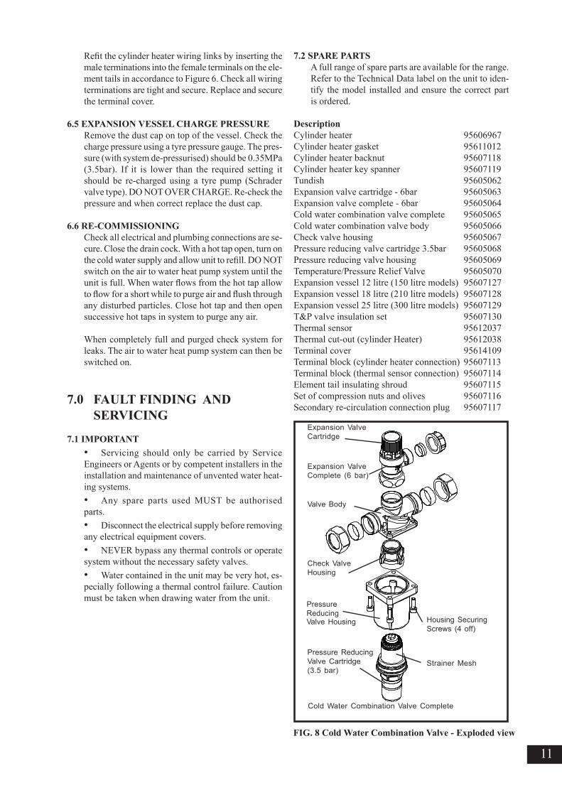
7.2 SPARE PARTSA full range of spare parts are available for the range. Refer to the Technical Data label on the unit to iden-tify the model installed and ensure the correct part is ordered.
FIG. 8 Cold Water Combination Valve - Exploded view
12
7.3 FAULT FINDINGThe Fault Finding chart below will enable operational faults to be identified and their possible causes rectified. Any work carried out on the unvented water cylinder and its associated controls MUST be carried out by a competent installer for unvented water heating systems. In case of doubt contact installer.
TABLE 5 Fault Finding Chart
WARNINGDO NOT TAMPER WITH ANY OF THE SAFETY VALVES OR CONTROLS SUPPLIED WITH THE UNIT AS THIS WILL INVALI-DATE ANY GUARANTEE
F AU L T P OS S IB L E C AU S E R E M E D YNo hot water flow 1. M ains s upply off 1. Chec k and turn on mains water supply
2. M a i n s w a t e r f i l t e r ( i ffitted) blocked .
3. Cold W ater Com binat ionvalves fitted incorrectly.
3. Chec k and refit as required
1. Cont ro l le r on Heat PumpHydro Un i t se t to spaceheat ing on ly .
1. Chec k set t ing
2. Heat Pump not working 2. Check opera t ion o f HeatPump. I f a fau l t i s suspec tedconsu l t the Heat Pump manua l .
3 . Check sensor opera t ion . Rep lace i f necessary .
1. Water storage temperatureon Hydro Unit controller is settoo high.
2. Turn of f water supply.Remove f i l ter and c lean inaccordance wi th manufacturersinstruct ions.
water supply.
1. C y l i n d e r h e a t e rt h e r m a l c u t - o u t h a s o p e r a t e d .
1. C h e c k . R e s e t b yp u s h i n g b u t t o n o n c u t - o u t .
2. Faul ty water cy l indertemperature sensor.
2. Check sensor operat ion.Replace i f necessary.
3. Faul ty water cy l indertemperature sensor
1. Check and adjust as required.
2. Faul ty water cy l indertemperature sensor.
2. Check sensor operat ion.Replace i f necessary.
Water f rom hot taps iscold
Water f rom hot taps isonly warm
Water f rom hot taps istoo hot
Water d ischarges f romExpansion Valve
1. INTERMITTENTLYExpansion Vessel charge has reduced below 0.35MPa(3.5bar)
1. See Sect ion 6.5 for re-charging procedure
2. CONTINUALLYa. Cold Water Combinat ionValve Pressure Reducernot working correct ly
a. Check pressure f rom ColdWater Combinat ion Valve. I fgreater than 0.35MPa (3.5bar)replace Pressure Reducercart r idgeb. Remove Expansion Valve cart r idge. Check condi t ion ofseat . I f necessary f i t newExpansion Valve cart r idge.
b. Expansion Valve seatdamaged
Water d ischarges f romT&P Rel ief Valve
1.Thermal contro l fa i lureNOTE water wi l l be very hot
1.Switch of f power to cyl inderheater and shut down Hydro Uni t . DO NOT turn of f water supply. When discharge stopscheck al l thermal contro ls, replace i f faul ty .
13
8.0 USER INSTRUCTIONS
8.1 WARNINGSIF WATER ISSUES FROM THE TEMPERA-TURE/PRESSURE RELIEF VALVE ON THE UNIT SWITCH OFF ELECTRICAL SUPPLY TO THE AIR TO WATER HEAT PUMP SYSTEM. DO NOT TURN OFF ANY WATER SUPPLY. CONTACT A COMPETENT INSTALLER FOR UNVENTED WATER CYLINDERS TO CHECK THE SYSTEM.
DO NOT TAMPER WITH ANY OF THE SAFETY VALVES FITTED TO THE SYSTEM. IF A FAULT IS SUSPECTED CONTACT A COMPETENT INSTALLER.
8.2 TEMPERATURE CONTROL The water storage temperature at the air to water heat pump water cylinder is set at the control panel of the Hydro Unit. This can be set to give temperatures in the range of 40°C to 75°C, 60°C is recommended. Refer to the Air to Water Owners Manual for details of how to adjust the temperature if necessary.The water cylinder is fitted with an over temperature thermal cut-out that will operate should the thermo-static control fail.
DO NOT bypass the thermal cut-out in any cir-cumstances.
8.3 FLOW PERFORMANCEWhen initially opening hot outlets a small surge in flow may be noticed as pressures stabilize. This is quite normal with unvented systems. In some areas cloudiness may be noticed in the hot water. This is due to aeration of the water, is quite normal and will quickly clear.
8.4 OPERATIONAL FAULTSOperational faults and their possible causes are de-tailed in Section 7.0. It is recommended that faults should be checked by a competent installer.
The air volume within the expansion vessel will peri-odically require recharging to ensure expanded water is accommodated within the unit. A discharge of water INTERMITTENTLY from the Expansion Valve will indicate the air volume has reduced to a point where it can no longer accommodate the expansion.
14
9.0 GUARANTEE
For warranty details please contact your ESTIA Heat Pump supplier.
This product is guaranteed provided that:
• The unit has been installed in accordance with the Installation and Service instructions and all relevant Codes of Practice and Regulations in force at the time of installation, and that all necessary inlet controls and safety valves have been fitted correctly.
• Any valves and controls are of the recommended type and specification.
• It has only been used for the storage of potable water. (Max. 250mg/l chloride)
• The unit has not been modified or tampered with in any way, and has been regularly maintained as detailed in the Installation and Service instructions.
• The unit has not been subjected to high chloride levels in the water supply or incorrect disinfection methods.
• Following commissioning the unit is put into service within a period of 7 days. If this is not the case it must either be drained or regularly flushed as required in the section ‘Commissioning - Warning’.The unit is not guaranteed against damage by frost, and the inner container with integral cylinder heater is not guaranteed against excessive scale build-up.
Periodic loss of charge pressure from the Expan-sion Vessel is normal (indicated by an intermittent discharge of water from the Expansion Valve) and is not covered under the product guarantee. Refer to Section 6.5 for details on how to restore the Expansion Vessel charge pressure.
This guarantee DOES NOT cover the ESTIA Air to Water Heat Pump Outdoor Unit or ESTIA Hydro Unit.
This guarantee does not affect your statutory rights.
ENVIRONMENTAL INFORMATION
These products are manufactured from many recyclable materials. At the end of their useful life they should be disposed of at a Local Authority Recycling Centre in order to realise the full environmental benefits.
Insulation is by means of an approved CFC/HCFC free polyurethane foam with an ozone depletion factor of zero.
15
NOTES
16
Our policy is one of continuous product development and, as such, we reserve the right to change specifications without notice.