Page 1
Institute of Science & Technology, klawad, 2012-13
CHAPTER-1
INTRODUCTION OF GSM
1.1 INTRODUCTION
GSM (Global System for Mobile Communication) is a globally accepted standard for
digital cellular communication. GSM is the name of a standardization group established in
1982 to create a common European mobile telephone standard that would formulate
specifications for a pan-European mobile cellular radio system operating at 900MHz.It is
used to describe technologies for second generation (2G) digital cellular networks.
Developed as a replacement for first generation (1G) analog cellular networks, the GSM
standard originally described a digital, circuit switched network optimized for full
duplex voice telephony. The standard was expanded over time to include first circuit
switched data transport, then packet data transport via GPRS (General Packet Radio
Services). Packet data transmission speeds were later increased via EDGE (Enhanced Data
rates for GSM Evolution) referred as EGPRS.
Development in wireless technology
Fig1.1: Graph representation
1
Page 2
Institute of Science & Technology, klawad, 2012-13
1.2 COMPANY DESCRIPTION
The Aircel Group is a joint venture between Maxis Communications Berhad of Malaysia
and Apollo Hospital Enterprise Ltd of India, with Maxis Communications holding a
majority stake of 74%. Aircel commenced operations in 1999 and became the leading
mobile operator in Tamil Nadu within 18 months. In December 2003, it launched
commercially in Chennai and quickly established itself as a market leader – a position it
has held since.Aircel is currently operational in 22 telecom circles of India.
Aircel began its outward expansion in 2005 and met with unprecedented success in the
Eastern frontier circles. It emerged a market leader in Assam and in the North Eastern
provinces within 18 months of operations. During this period, the company gained a
foothold in 9 circles including Chennai, Tamil Nadu, Assam, North East, Orissa, Bihar,
Jammu & Kashmir, Himachal Pradesh and West Bengal.
The Company has currently gained a momentum in the space of telecom in India post the
allocation of additional spectrum by the Department of Telecom, Govt. of India for 13 new
circles across India. These include Delhi (Metro), Mumbai (Metro), Andhra Pradesh,
Gujarat, Haryana, Karnataka, Kerala, Madhya Pradesh, Maharashtra & Goa, Rajasthan,
Punjab, UP (West) and UP (East).
Aircel has won many awards and recognitions. Voice and Data gave Aircel the highest
rating for overall customer satisfaction and network quality in 2006. Aircel emerged as the
top mid-size utility company in Businessworld’s ‘List of Best Mid-Size Companies’ in
2007. Additionally,Tele.net recognised Aircel as the best regional operator in 2008.
With over 41million customers in the country, Aircel, the fastest growing telecom company
in India, a full-fledged national operator. Aircel has won 3G spectrum across 13 circles and
BWA spectrum in 8 circles in recently spectrum auction.Aircel holds the highest amount of
next generation spectrum amongst all telecom operators in India
2
Page 3
Institute of Science & Technology, klawad, 2012-13
1.3 GSM Specifications
Bandwidth—the range of a channel’s limits; the broader the bandwidth, the
faster data can be sent
Bits per second (bps)—a single on-off pulse of data; eight bits are equivalent to one
byte
Frequency—the number of cycles per unit of time; frequency is measured in hertz (Hz)
Kilo (k)—kilo is the designation for 1,000; kbps represents 1,000 bits per second
Megahertz (MHz)—1,000,000 hertz (cycles per second)
Milliseconds (ms)—one-thousandth of a second
Watt (W)—a measure of power of a transmitter
There are three different types in GSM.
1. GSM 900
2. DCS 1800
3. PCS 1900
1.3.1 GSM 900
GSM 900 operates at 900 MHz frequency.
Up link operates on 890 MHz to 915 MHz Band.
Downlink operates on 935 MHz to 960MHz Band.
Up link / Downlink separation: 45 MHz.
GSM takes advantages of both FDMA & TDMA.
In 25MHz BW , 124 carriers are generated with channel spacing of 200KHz
(FDMA)
Each carrier is divided into 8 time slots (TDMA)
At any specific time 992 speech channels are made available in GSM 900
.
1.3.2 DCS 1800
DCS 1800 operates at 1800 MHz frequency.
Up link operates on 1715 MHz to 1785 MHz Band.
3
Page 4
Institute of Science & Technology, klawad, 2012-13
Downlink operates on 1805 MHz to1880 MHz Band.
Up link / Downlink separation: 95 MHz.
channel spacing : 200KHz (FDMA)
Each carrier is divided into 8 time slots (TDMA)
No. of carrier : 374
1.3.3 PCS 1800
PCS 1900 operates at 1900 MHz frequency.
Up link operates on 1850 MHz to 1910 MHz Band.
Downlink operates on 1930 MHzto1990 MHz Band.
Up link / Downlink separation: 80 MHz.
1.4 TECHNOLOGIES IN WIRELESS COMMUNICATION
FDMA (Frequency Division Multiple Access)
TDMA (Time Division Multiple Access)
CDMA (Code Division Multiple Access)
1.4.1 FDMA (Frequency Division Multiple Access)
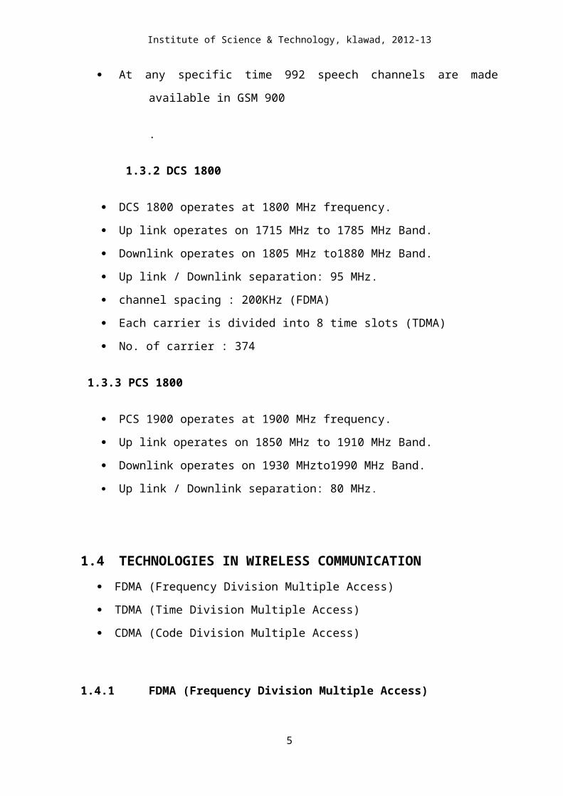
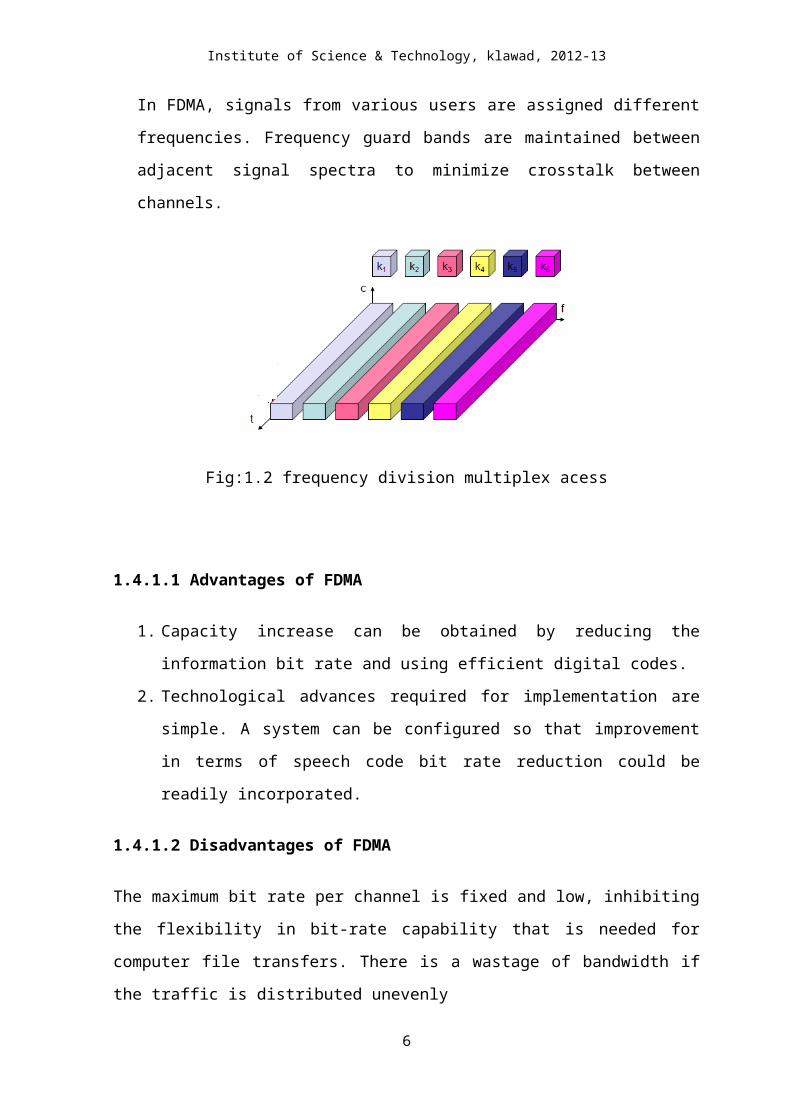
In FDMA, signals from various users are assigned different frequencies. Frequency
guard bands are maintained between adjacent signal spectra to minimize crosstalk
between channels.
Fig:1.2 frequency division multiplex acess
4
Page 5
Institute of Science & Technology, klawad, 2012-13
1.4.1.1 Advantages of FDMA
1. Capacity increase can be obtained by reducing the information bit rate and using
efficient digital codes.
2. Technological advances required for implementation are simple. A system can be
configured so that improvement in terms of speech code bit rate reduction could be
readily incorporated.
1.4.1.2 Disadvantages of FDMA
The maximum bit rate per channel is fixed and low, inhibiting the flexibility in bit-rate
capability that is needed for computer file transfers. There is a wastage of bandwidth if the
traffic is distributed unevenly
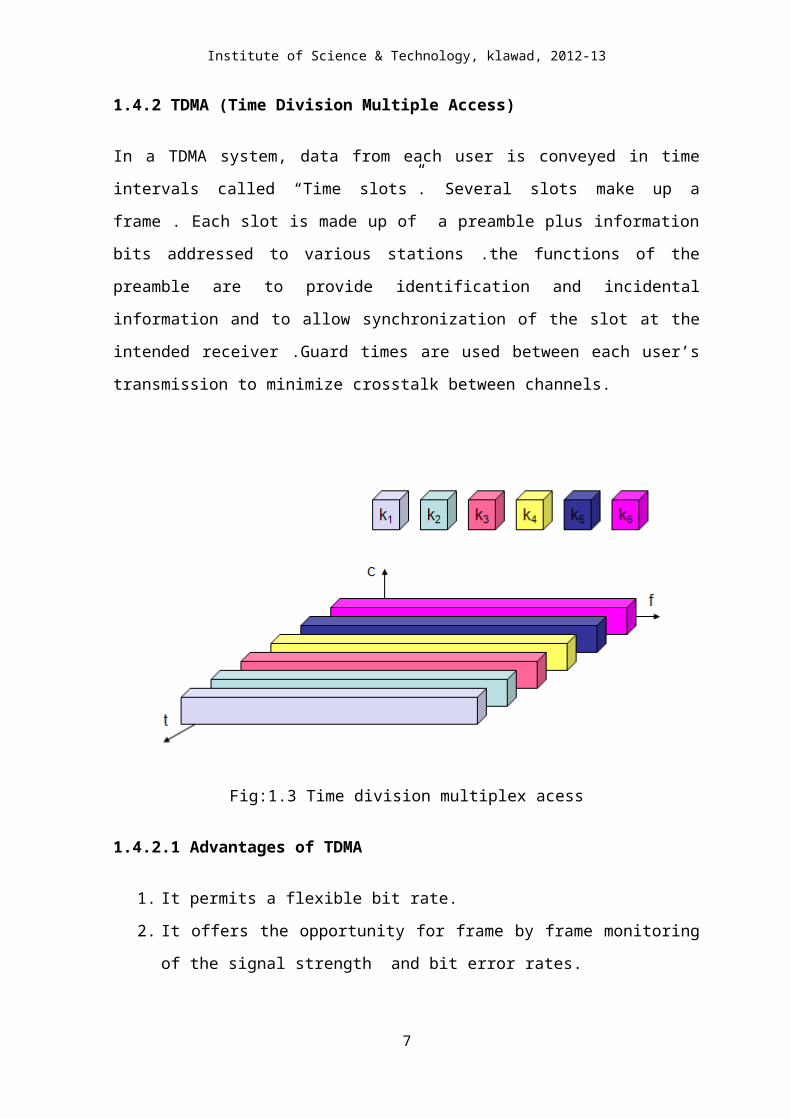
1.4.2 TDMA (Time Division Multiple Access)
In a TDMA system, data from each user is conveyed in time intervals called “Time slots”.
Several slots make up a frame . Each slot is made up of a preamble plus information bits
addressed to various stations .the functions of the preamble are to provide identification and
incidental information and to allow synchronization of the slot at the intended
receiver .Guard times are used between each user’s transmission to minimize crosstalk
between channels.
5
Page 6
Institute of Science & Technology, klawad, 2012-13
Fig:1.3 Time division multiplex acess
1.4.2.1 Advantages of TDMA
1. It permits a flexible bit rate.
2. It offers the opportunity for frame by frame monitoring of the signal strength and
bit error rates.
3. It transmits each signal with sufficient guard time between time slots.
1.4.2.2 Disadvantages of TDMA
1. Precise synchronization is required.
2. It can only operate through a delay system.
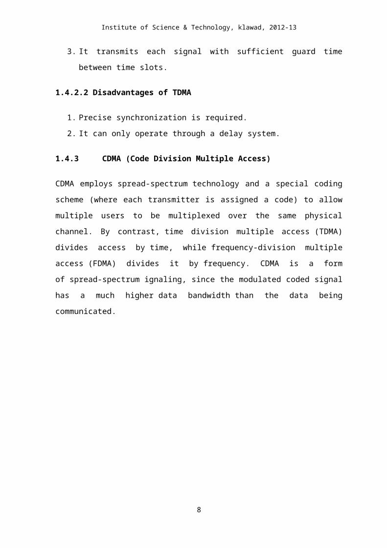
1.4.3 CDMA (Code Division Multiple Access)
CDMA employs spread-spectrum technology and a special coding scheme (where each
transmitter is assigned a code) to allow multiple users to be multiplexed over the same
physical channel. By contrast, time division multiple access (TDMA) divides access
by time, while frequency-division multiple access (FDMA) divides it by frequency. CDMA
is a form of spread-spectrum ignaling, since the modulated coded signal has a much
higher data bandwidth than the data being communicated.
6
Page 7
Institute of Science & Technology, klawad, 2012-13
Fig:1.4 Code division multiple acess
1.4.3.1. Advantages of CDMA
1. The transmission power is extremely small, so conversation is having not only less
radiation but also the mobiles have longer battery life
2. The call quality is very good even if there is large background noise.
1.4.3.2 Disadvantages of CDMA
1. It does not offer international roaming.
2. The CDMA handsets can only be used with a fixed network provider,it cannot be
changed.
7
Page 8
Institute of Science & Technology, klawad, 2012-13
CHAPTER-2
HISTORY OF WIRELESS COMMUNICATION
2.1 HISTORY 1982-Groupe Spécial Mobile established by the CEPT.
1986 –Reservation of the 900 MHz spectrum band for GSM agreed in the EC –
Telecommunications Council. Trials of different digital radio transmission schemes and
different speech codes in several countries.
1987 –Basic parameters of the GSM standard agreed in February.
1988 –Completion of first set of detailed GSM specifications for infrastructure.
1989- Groupe Spéciale Mobile (transferred to an ETSI technical committee)defines the
GSM standard as the internationally accepted digital cellular telephony standard.
1990 –GSM adaptation work started for the DCS1800 band.
1991- First GSM call made by Radiolinja in Finland.
1992- First international roaming agreement signed between Telecom Finland and
Vodafone (UK).First SMS sent.
1993- Telstra Australia becomes the first non-European operator. Worlds first
DCS1800 (later GSM1800) network opened in the UK.
1994- GSM Phase 2 data/fax bearer services launched.GSM MoU membership
surpasses 100 operators.GSM subscribers hit one million.
1995 -117 GSM networks on air. The number of GSM subscribers worldwide exceeds
10 million. Fax, data and SMS services started, video over GSM demonstrated. The
first North American PCS 1900 (now GSM 1900) network opened.
1996- First GSM networks in Russia and China go live. Number of GSM subscribers
hits 50 million.
1997 –First tri-band handsets launched.
1998- Number of GSM subscribers worldwide over 100 million.
1999- WAP trials begin in France and Italy.
2000-First commercial GPRS services launched.First GPRS handsets enter the
market.Five billion SMS messages sent in one month.
2001 –First 3GSM (W-CDMA) network goes live.Number of GSM subscribers exceed
500 million worldwide.
8
Page 9
Institute of Science & Technology, klawad, 2012-13
2003- First EDGE networks go live.Membership of GSM Association breaks through
200-country barrier.Over half a billion handsets produced in a year.
2008- GSM surpasses three billion customer threshold.
2.2 GSM ARCHITECTURE
Fig:2.1 GSM architecture
It consists of mainly three parts
1. BSS (Base Station System)
2. SS (Switching System)
3. OSS (Operation and Support System)
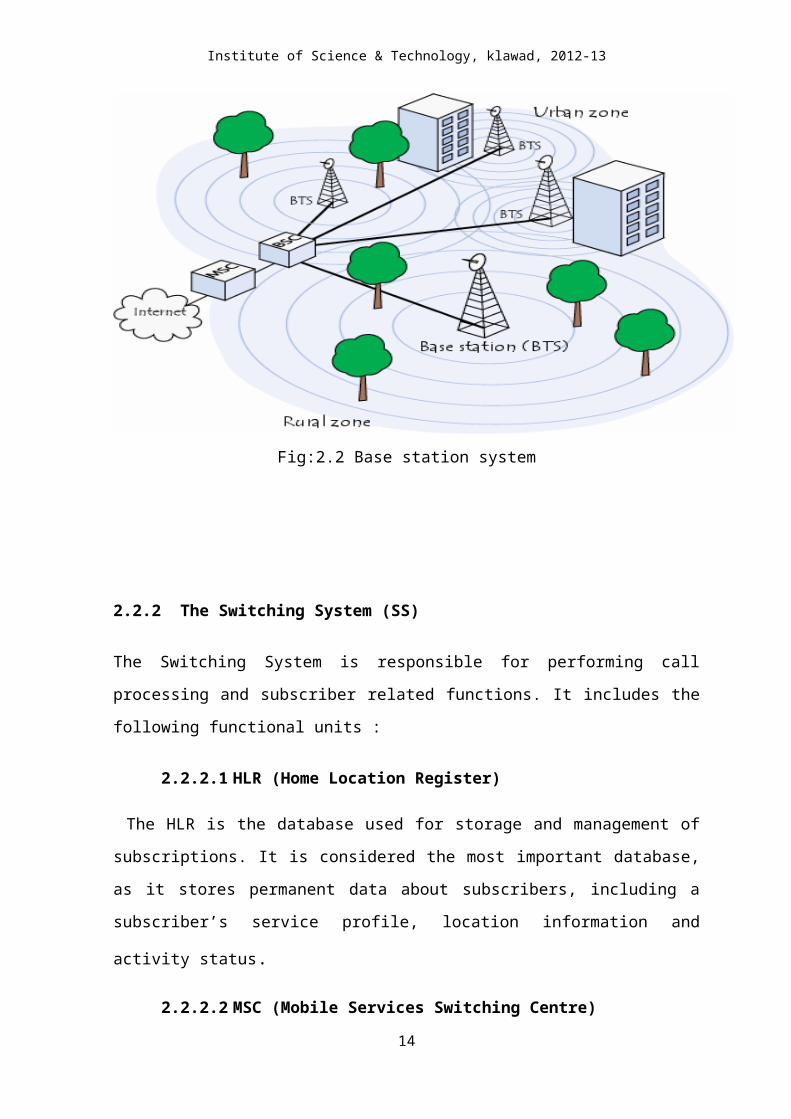
2.2.1 The Base Station System (BSS)
All radio related functions are performed in the BSS, which consists of base station
controllers (BSC’s) and base transceiver stations (BTS’s). BSS is responsible for
handling traffic and signaling between a mobile phone and the network switching
9
Page 10
Institute of Science & Technology, klawad, 2012-13
system. It carries out transcoding of speech channels, allocation of radio channels to
mobile phones, paging, transmission and reception over the air interface and many
other tasks related to radio network.
The two main components of BSS are :
2.2.1.1 BTS (Base Transceiver Station)
It is the part of BSS that directly communicates with the Mobile Station (MS) and handles
the radio interface. It is the radio equipment (transceivers and antennas) needed to service
each cell in the network. A group of BTS’s are controlled by a BSC.
2.2.1.2 BSC (Base Station Controller)
The BSC provides all the control functions and physical links between the MSC and the
BTS. It is a high capacity switch that provides functions such as handover, cell
configuration data , and control of RF(radio frequency) power levels in BTS. A number of
BSC’s are controlled by MSC.
Fig:2.2 Base station system
10
Page 11
Institute of Science & Technology, klawad, 2012-13
2.2.2 The Switching System (SS)
The Switching System is responsible for performing call processing and subscriber related
functions. It includes the following functional units :
2.2.2.1 HLR (Home Location Register)
The HLR is the database used for storage and management of subscriptions. It is
considered the most important database, as it stores permanent data about subscribers,
including a subscriber’s service profile, location information and activity status.
2.2.2.2 MSC (Mobile Services Switching Centre)
It performs the telephony switching functions of the system. It controls calls to and from
other telephone and data systems. It also performs such functions like toll ticketing,
network interfacing, common channel signaling and others.
2.2.2.3 VLR (Visitor Location Register)
It is the database that contains the temporary information about the subscribers that is
needed by the MSC in order to service visiting subscribers. The VLR is always integrated
with MSC .
2.2.2.4 AUC (Authentication Centre)
A unit called AUC provides authentication and encryption parameters that verify the
user’s identity and ensure the confidentiality of each call. The AUC protects the network
operators from different types of fraud found in today’s cellular world.
2.2.2.5 EIR (Equipment Identity Register)
The EIR is a database that contains information about the identity of mobile equipment
that prevents calls from stolen, unauthorized, or defective mobile stations. The AUC and
EIR are implemented as stand-alone nodes or as a combined AUC/EIR node.
11
Page 12
Institute of Science & Technology, klawad, 2012-13
Fig:2.3 Switching system
2.2.3 The Operation and Support System (OSS)
The operations and maintenance centre (OMC) is connected to all equipments in the
switching system and to BSC. The implementation of OMC is called the operation and
support system (OSS). The OSS is the functional entity from which the network operator
monitors and controls the system. The purpose of OSS is to offer the customer cost-
effective support for centralized , regional, and local operational and maintenance activities
that are required for a GSM network. An important function of OSS is to provide a
network overview and support the maintenance activities of different operation and
maintenance organizations.
12
Page 13
Institute of Science & Technology, klawad, 2012-13
CHAPTER-3
SERVICES,IDENTITES,OPERATIONS,CONTROL & AREA
3.1 GSM Telecommunication Services
The ETSI Standards define the telecommunication services. With D900/D1800 the
GSM telecommunication services offered to the GSM subscriber are subdivided as follows:
Bearer services (for data only)
Tele-services (for voice and data)
Supplementary services
Bearer services and tele-services are also called basic telecommunication services. The
use of GSM telecommunication services is subject to subscription. A basic subscription
permits participation in those GSM telecommunication services that are generally
available.
If a GSM subscriber roams out of the entitled area there is no possibility of establishing
communication (roaming not allowed), except the use of the tele-service emergency call.
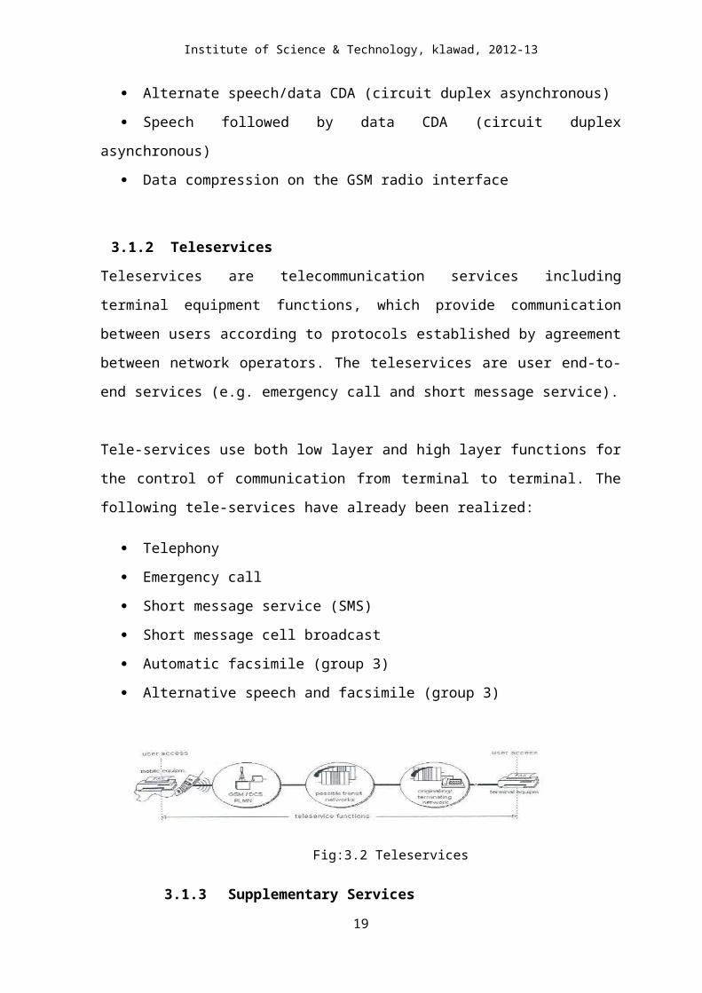
3.1.1 Bearer Services
Bearer services are telecommunication services providing the capability of transmission
of signals between access points. The bearer services describe what the network can offer
(e.g. speech, data and fax).
The bearer services are pure transport services for data. Some of the transmission modes and
rates already used in modern data networks are implemented; others are planned. The following,
already implemented, bearer services provide unrestricted information transfer between the
reference points in the mobile stations.
13
Page 14
Institute of Science & Technology, klawad, 2012-13
Fig:3.1 Bearer services
Data CDA (circuit duplex asynchronous) + basic PAD (packet assembler
Disassembler) access
Data CDS (circuit duplex synchronous)
PAD CDA (dedicated PAD access)
Alternate speech/data CDA (circuit duplex asynchronous)
Speech followed by data CDA (circuit duplex asynchronous)
Data compression on the GSM radio interface
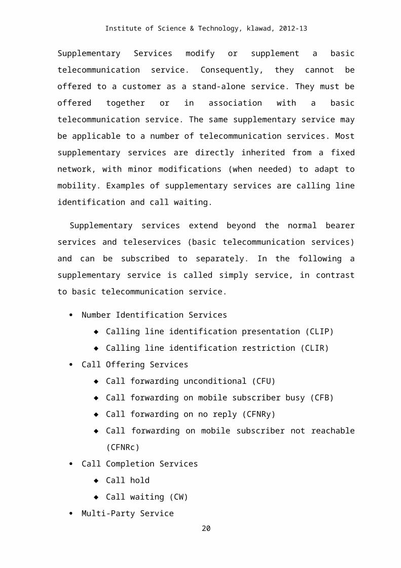
3.1.2 Teleservices
Teleservices are telecommunication services including terminal equipment functions,
which provide communication between users according to protocols established by
agreement between network operators. The teleservices are user end-to-end services (e.g.
emergency call and short message service).
Tele-services use both low layer and high layer functions for the control of communication
from terminal to terminal. The following tele-services have already been realized:
Telephony
Emergency call
Short message service (SMS)
Short message cell broadcast
Automatic facsimile (group 3)
Alternative speech and facsimile (group 3)
Fig:3.2 Teleservices
3.1.3 Supplementary Services
Supplementary Services modify or supplement a basic telecommunication service.
Consequently, they cannot be offered to a customer as a stand-alone service. They must be 14
Page 15
Institute of Science & Technology, klawad, 2012-13
offered together or in association with a basic telecommunication service. The same
supplementary service may be applicable to a number of telecommunication services. Most
supplementary services are directly inherited from a fixed network, with minor
modifications (when needed) to adapt to mobility. Examples of supplementary services are
calling line identification and call waiting.
Supplementary services extend beyond the normal bearer services and teleservices
(basic telecommunication services) and can be subscribed to separately. In the following a
supplementary service is called simply service, in contrast to basic telecommunication
service.
Number Identification Services
Calling line identification presentation (CLIP)
Calling line identification restriction (CLIR)
Call Offering Services
Call forwarding unconditional (CFU)
Call forwarding on mobile subscriber busy (CFB)
Call forwarding on no reply (CFNRy)
Call forwarding on mobile subscriber not reachable (CFNRc)
Call Completion Services
Call hold
Call waiting (CW)
Multi-Party Service
Charging Services
Advice of charge (AOC)
Call Restriction Services
Barring of all outgoing calls (BAOC)
Barring of all outgoing international calls (BOIC)
Barring of all outgoing international calls except to home PLMN country
(BOICexHC)
Barring of all incoming calls (BAIC)
Barring of all incoming calls when roaming outside home PLMN country
(BIC Roam)
Closed User Group (CUG)
15
Page 16
Institute of Science & Technology, klawad, 2012-13
3.2 GSM IDENTITIES
3.2.1 Mobile Station ISDN Number (MSISDN)
The MSISDN is a number, which uniquely identifies a mobile telephone subscription in
the PSTN numbering plan. The MS international number must be ignall after the
international prefix in order to obtain a mobile subscriber in another country. The MSISDN
numbers is composed of the country code (CC) followed by the National Destination Code
(NDC), Subscriber Number (SN), which shall not exceed 15 digits. Here too the first two
digits of the SN identify the HLR where the mobile subscriber is administrated.
In GSM 900/1800, The MSISDN consists of following:
MSISDN = CC + NDC + SN
National Mobile number
International Mobile station ISDN Number
3.2.2 The Mobile Station Roaming Number (MSRN)
The MSRN is allocated on temporary basis when the MS roams into another numbering
area. The MSRN number is used by the HLR for rerouting calls to the MS. It is assigned
upon demand by the HLR on a per-call basis. The MSRN for PSTN/ISDN routing shall
have the same structure as international ISDN numbers in the area in which the MSRN is
allocated. The HLR knows in what MSC/VLR service area the subscriber is located. At the
reception of the MSRN, HLR sends it to the GMSC, which can now route the call to the
MSC/VLR exchange where the called subscriber is currently registered.
3.2.3 International Mobile Subscriber Identity (IMSI)
An IMSI is assigned to each authorized GSM user. It consists of a mobile country
code (MCC), mobile network code (MNC) (to identify the PLMN), and a PLMN unique
mobile subscriber identification number (MSIN). The IMSI is the only absolute identity
that a subscriber has within the GSM system. The IMSI consists of the MCC followed by
the MNC and MSIN and shall not exceed 15 digits. It is used in the case of system-internal
ignalling transactions in order to identify a subscriber. The first two digits of the MSIN
identify the HLR where the mobile subscriber is administrated.
The IMSI consists of three parts:
16
Page 17
Institute of Science & Technology, klawad, 2012-13
IMSI = MCC + MNC + MSIN
Where,
MCC = Mobile Country Code
MNC = Mobile Network Code
MISN = Mobile station Identification Code
3.2.4 Temporary mobile subscriber identity (TMSI)
A TMSI is a MSC-VLR specific alias that is designed to maintain user confidentiality.
It is assigned only after successful subscriber authentication. The correlation of a TMSI to
an IMSI only occurs during a mobile subscriber’s initial transaction with an MSC (for
example, location updating). Under certain condition (such as traffic system disruption and
malfunctioning of the system), the MSC can direct individual TMSIs to provide the MSC
with their IMSI.
3.2.5 International Mobile Equipment Identity (IMEI)
The IMEI is the unique identity of the equipment used by a subscriber by each PLMN
and is used to determine authorized (white), unauthorized (black), and malfunctioning
(gray) GSM hardware. In conjunction with the IMSI, it is used to ensure that only
authorized users are granted access to the system.
The IMEI consists of the following:
IMEI = TAC + FAC + SNR + SVN
Where,
TAC = type approval code
FAC= Final assembly code
SNR = Serial number
SVN = Software Version Number
3.2.6 Location Area Identity (LAI)
The LAI is used for paging and it tells MSC in which location area the MS is located.
LAI = MCC + MNC + LAC
Where,
MCC = Mobile Country Code
MNC = Mobile Network Code
LAC = location Area Code 17
Page 18
Institute of Science & Technology, klawad, 2012-13
3.2.7 Cell Global identity (CGI):
This is used for cell identification, within the location area. This is done by adding a
cell identity.
CGI = MCC +MNC + LAC +CI
Where,
CI = cell identity (16 digits maximum)
3.2.8 PERSONAL IDENTITY NO.
It is used to unlock the MS. If one enters the wrong PIN three times it will lock the
SIM. The SIM can be protected by use of PIN password.
3.2.9 PIN UNBLOCKING KEY (PUK)
In case of PIN, the PUK is needed for unlocking the SIM again. PUK is numeric only,
with eight digits. If a correct PUK is entered, an indication is given to the user. After 10
consecutive incorrect entries the SIM is blocked. Either the IMSI or the MSISDN Number
may access the subscriber data. Some of the parameters like IAI will be continuously
updated to reflect the current location of the subscriber. The SIM is capable of storing
additional information such as accumulated call charges. This information will be
accessible to the customer via handset key entry.
3.3 OPERATION & MAINTENANCE CENTER
The operations and maintenance center (OMC) is connected to all equipment in the
switching system and to the BSC. The implementation of OMC is called the operation and
support system (OSS). The OSS is the functional entity from which the network operator
monitors and controls the system. The purpose of OSS is to offer the customer cost-
effective support for centralized, regional and local operational and maintenance activities
that are required for a GSM network. An important function of OSS is to provide a network
overview and support the maintenance activities of different operation and maintenance
organizations.
18
Page 19
Institute of Science & Technology, klawad, 2012-13
The OMC provides alarm-handling functions to report and log alarms generated by the
other network entities. The maintenance personnel at the OMC can define that criticality of
the alarm. Maintenance covers both technical and administrative actions to maintain and
correct the system operation, or to restore normal operations after a breakdown, in the
shortest possible time.
The fault management functions of the OMC allow network devices to be manually or
automatically removed from or restored to service. The status of network devices can be
checked, and tests and diagnostics on various devices can be invoked. For example,
diagnostics may be initiated remotely by the OMC. A mobile call trace facility can also be
invoked. The performance management functions included collecting traffic statistics from
the GSM network entities and archiving them in disk files or displaying them for analysis.
Because a potential to collect large amounts of data exists, maintenance personal can select
which of the detailed statistics to be collected based on personal interests and past
experience. As a result of performance analysis, if necessary, an alarm can be set remotely.
The OMC provides system change control for the software revisions and configuration
data bases in the network entities or uploaded to the OMC. The OMC also keeps track of
the different software versions running on different subsystem of the GSM.
The location area is a group of cells. It is the area in which the subscriber is paged.
Each LA is served by one or more base station controllers, yet only by a single MSC. Each
LA is assigned a location area identity (LAI) number.
3.4 The Radio interface (Um)
The International Telecommunication Union (ITU), which manages the international
allocation of radio spectrum (among other functions) allocated the bands 890-915 MHz for
the uplink (mobile station to base station) and 935-960 MHz for the downlink (base station
to mobile station) for mobile networks in Europe. Since this range was already being used
in the early 1980s by the analog systems of the day, the CEPT had the foresight to reserve
the top 10 MHz of each band for the GSM network that was still being developed.
Eventually, GSM will be allocated the entire 2x25 MHz bandwidth.
Since radio spectrum is a limited resource shared by all users, a method must be
devised to divide up the bandwidth among as many users as possible. The method chosen
by GSM is a combination of Time and Frequency Division Multiple Access
19
Page 20
Institute of Science & Technology, klawad, 2012-13
(TDMA/FDMA). The FDMA part involves the division by frequency of the total 25 MHz
bandwidth into 124 carrier frequencies of 200 kHz bandwidth. One or more carrier
frequencies are then assigned to each base station. Each of these carrier frequencies is then
divided in time, using a TDMA scheme, into eight time slots. One time slot is used for
transmission by the mobile and one for reception. They are separated in time so that the
mobile unit does not receive and transmit at the same time, a fact that simplifies the
electronics.
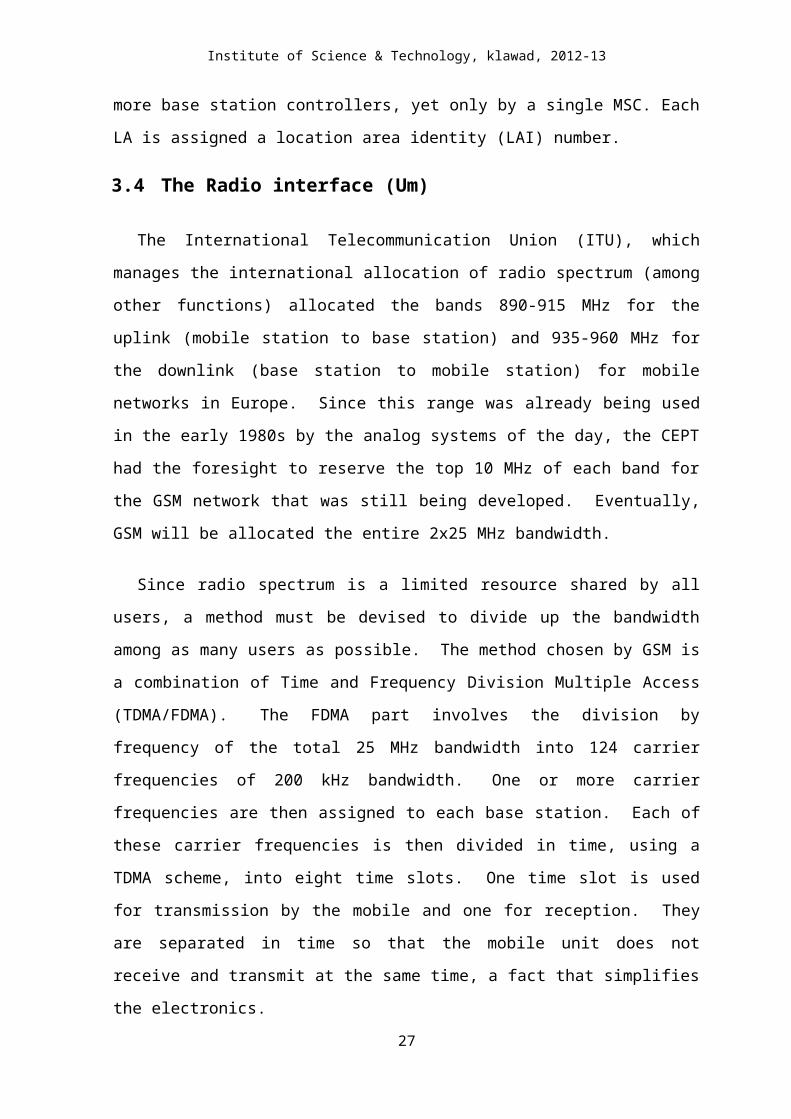
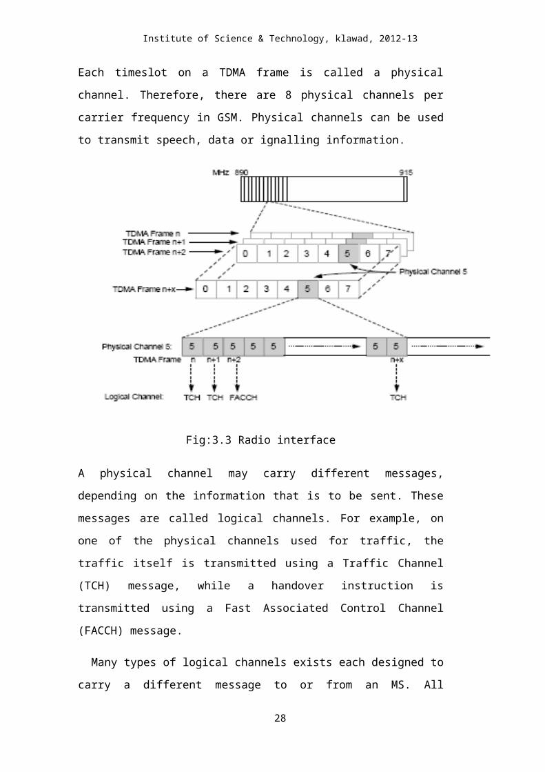
Each timeslot on a TDMA frame is called a physical channel. Therefore, there are 8
physical channels per carrier frequency in GSM. Physical channels can be used to
transmit speech, data or ignalling information.
Fig:3.3 Radio interface
A physical channel may carry different messages, depending on the information that
is to be sent. These messages are called logical channels. For example, on one of the
physical channels used for traffic, the traffic itself is transmitted using a Traffic
Channel (TCH) message, while a handover instruction is transmitted using a Fast
Associated Control Channel (FACCH) message.
Many types of logical channels exists each designed to carry a different message
to or from an MS. All information to and from an MS must be formatted correctly,
20
Page 21
Institute of Science & Technology, klawad, 2012-13
so that the receiving device can understand the meaning of different bits in the
message.
3.5 CONTROL CHANNELS
When an MS is switched on, it searches for a BTS to connect to. The MS scans the entire
frequency band, or, optionally, uses a list containing the allocated carrier frequencies for this
operator. When the MS finds the strongest carrier, it must then determine if it is a control
channel. It does so by searching for a particular logical channel called Broadcast Control
Channel (BCCH).
A frequency carrying BCCH contains important information for an MS, including e.g. the
current LA identity, synchronization information and network identity. Without such
information, an MS cannot work with a network. This information is broadcast at regular
intervals, leading to the term Broadcast Channel (BCH) information.
21
Page 22
Institute of Science & Technology, klawad, 2012-13
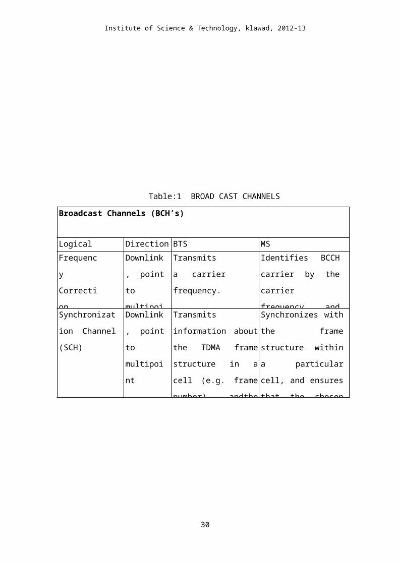
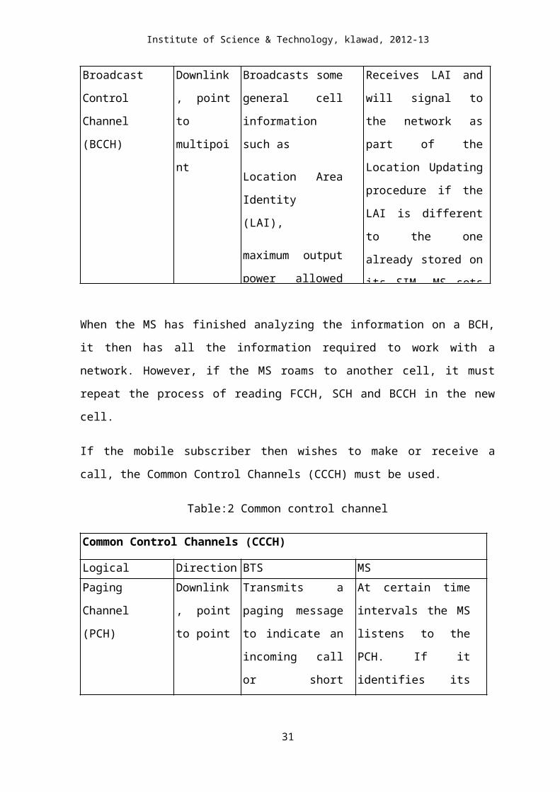
Table:1 BROAD CAST CHANNELS
Broadcast Channels (BCH’s)
Logical Channel Direction BTS MS
Frequency
Correction
Channel
(FCCH)
Downlink,
point to
multipoint
Transmits a
carrier
frequency.
Identifies BCCH carrier
by the carrier frequency
and synchronizes with
the frequency.
Synchronization
Channel (SCH)
Downlink,
point to
multipoint
Transmits information
about the TDMA frame
structure in a cell (e.g.
frame number) andthe
BTS identity (Base
Station Identity Code
(BSIC)).
Synchronizes with the
frame structure within a
particular cell, and
ensures that the chosen
BTS is a GSM BTS -
BSIC can only be
decoded by an MS if the Broadcast Control
Channel (BCCH)
Downlink,
point to
multipoint
Broadcasts some
general cell
information such as
Location Area
Identity (LAI),
maximum output
power allowed in the
cell and
the identity of BCCH
carriers for
Receives LAI and will
signal to the network as
part of the Location
Updating procedure if the
LAI is different to the one
already stored on its SIM.
MS sets its output power
level based on the
information received on
the BCCH. Also, the MS
stores a list of BCCH
carriers on which it will
When the MS has finished analyzing the information on a BCH, it then has all the
information required to work with a network. However, if the MS roams to another cell, it
must repeat the process of reading FCCH, SCH and BCCH in the new cell.
If the mobile subscriber then wishes to make or receive a call, the Common Control Channels
(CCCH) must be used.
22
Page 23
Institute of Science & Technology, klawad, 2012-13
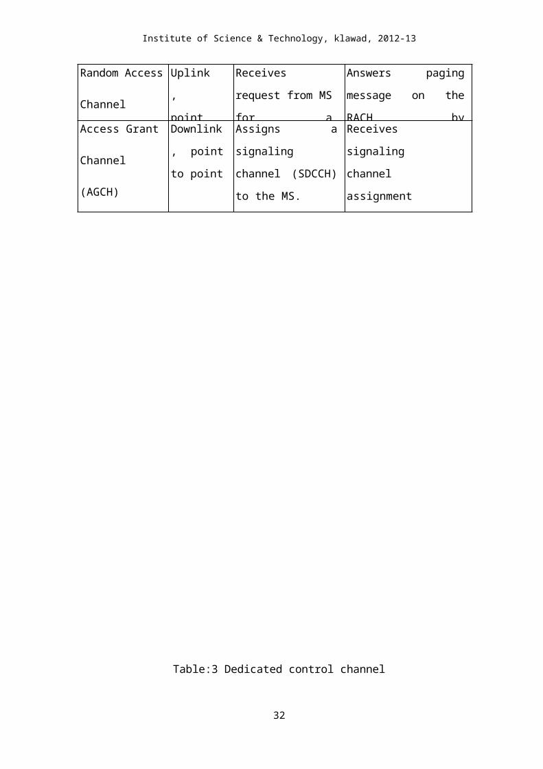
Table:2 Common control channel
Common Control Channels (CCCH)
Logical Channel Direction BTS MS
Paging Channel
(PCH)
Downlink,
point to
point
Transmits a paging
message to indicate
an incoming call or
short message. The
paging message
contains the identity
number of the mobile
At certain time intervals
the MS listens to the
PCH. If it identifies its
own mobile subscriber
identity number on the
PCH, it will respond.
Random Access
Channel
Uplink,
point to
point
Receives request from
MS for a signaling
channel (to be used
for call set-up).
Answers paging message
on the RACH by
requesting a signaling
channel.Access Grant
Channel
(AGCH)
Downlink,
point to
point
Assigns a signaling
channel (SDCCH) to
the MS.
Receives signaling
channel assignment
(SDCCH).
23
Page 24
Institute of Science & Technology, klawad, 2012-13
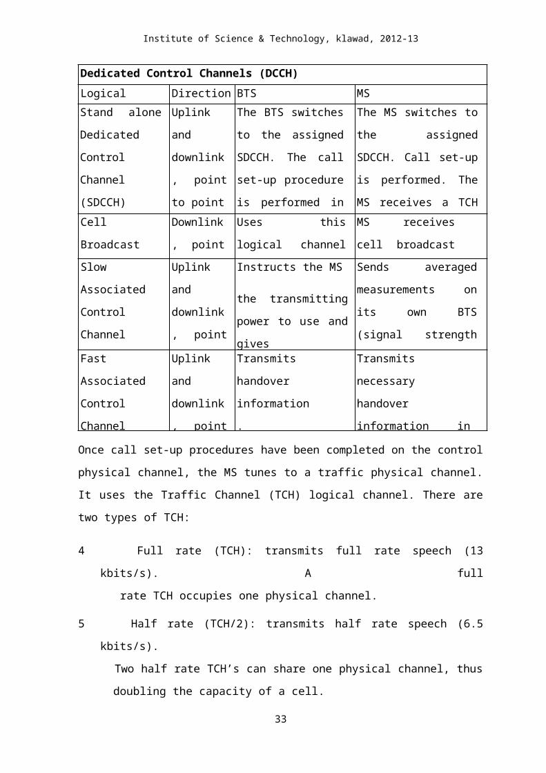
Table:3 Dedicated control channel
Dedicated Control Channels (DCCH)
Logical Channel Direction BTS MS
Stand alone
Dedicated Control
Channel
(SDCCH)
Uplink and
downlink,
point to
point
The BTS switches to
the assigned SDCCH.
The call set-up
procedure is performed
in idle mode. The BSC
assigns a TCH.
(SDCCH is also used to
The MS switches to the
assigned SDCCH. Call set-
up is performed. The MS
receives a TCH assignment
information (carrier and
time slot).Cell Broadcast
Channel
Downlink,
point to
multipoint
Uses this logical channel
to transmit short
message service cell
MS receives cell
broadcast messages.
Slow Associated
Control Channel
(SACCH)
Uplink and
downlink,
point to
point
Instructs the MS
the transmitting power to
use and gives
instructions on timing
advance (TA).
Sends averaged
measurements on its own
BTS (signal strength and
quality) and neighboring
BTS’s (signal strength).
The MS continues to use Fast Associated
Control Channel
(FACCH)
Uplink and
downlink,
point to
point
Transmits
handover
information.
Transmits necessary
handover information in
access burst
Once call set-up procedures have been completed on the control physical channel, the MS
tunes to a traffic physical channel. It uses the Traffic Channel (TCH) logical channel. There
are two types of TCH:
4 Full rate (TCH): transmits full rate speech (13 kbits/s). A full
rate TCH occupies one physical channel.
5 Half rate (TCH/2): transmits half rate speech (6.5 kbits/s).
Two half rate TCH’s can share one physical channel, thus
doubling the capacity of a cell.
24
Page 25
Institute of Science & Technology, klawad, 2012-13
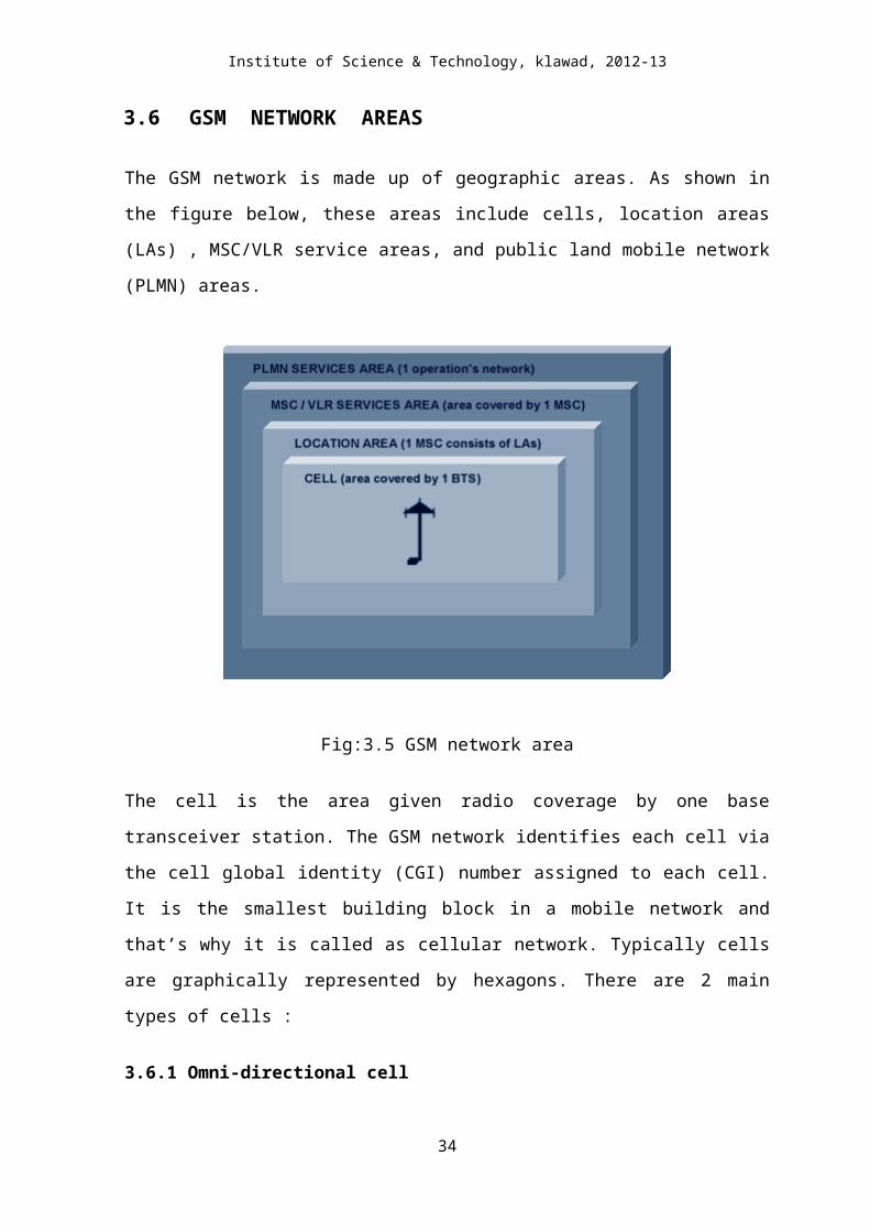
3.6 GSM NETWORK AREAS
The GSM network is made up of geographic areas. As shown in the figure below, these
areas include cells, location areas (LAs) , MSC/VLR service areas, and public land mobile
network (PLMN) areas.
Fig:3.5 GSM network area
The cell is the area given radio coverage by one base transceiver station. The GSM network
identifies each cell via the cell global identity (CGI) number assigned to each cell. It is the
smallest building block in a mobile network and that’s why it is called as cellular network.
Typically cells are graphically represented by hexagons. There are 2 main types of cells :
3.6.1 Omni-directional cell
An omni-directional cell (or omnicell) is served by a BTS with an antenna which
transmits equally in all directions( 360 deg).
3.6.2 Sector cell
A sector cell is the area of coverage from anantenna, which transmits, in a given
direction only. Forexample, this may be equal to 120 degrees or 180 degrees ofan
equivalent omni- directional cell. One BTS can serve oneof these sector cells with a
25
Page 26
Institute of Science & Technology, klawad, 2012-13
collection of BTS’s at a siteserving more than one, leading to terms such as two-sectored
sites and more commonly three-sectored sites/
Omni-directional cell Sector
cell
Fig:3.6 Type of network
The location area is a group of cells. It is the area in which the subscriber is paged (the
setting up of channels for one to one communication between mobile transceiver and base
station). Each LA is served by one or more base station controllers, yet only by a single
MSC. Each LA is assigned a location area identity (LAI) number.
Fig:3.7 Location Areas
26
Page 27
Institute of Science & Technology, klawad, 2012-13
An MSC/VLR service area represents the part of GSM network that is covered by one
MSC and which is reachable, as it is registered in the VLR of the MSC.
Fig: MSC/VLR service areas
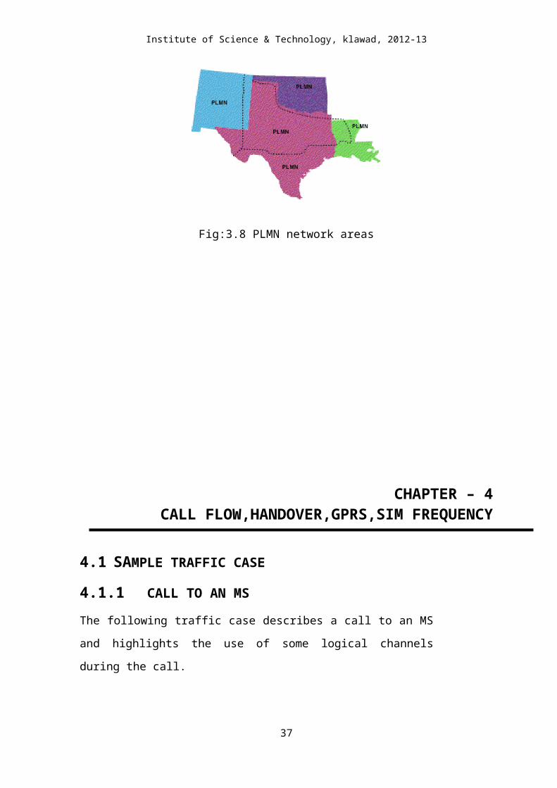
The PLMN service area is an area served by one network operator.
Fig:3.8 PLMN network areas
27
Page 28
Institute of Science & Technology, klawad, 2012-13
CHAPTER – 4CALL FLOW,HANDOVER,GPRS,SIM FREQUENCY
4.1 SAMPLE TRAFFIC CASE
4.1.1 CALL TO AN MS
The following traffic case describes a call to an MS and highlights the use of
some logical channels during the call.
Fig:4.1 Call to an MS
28
Page 29
Institute of Science & Technology, klawad, 2012-13
The MSC/VLR knows which LA the M S is located in. A paging message is sent to the
BSC’s controlling the LA.
The BSC’s distribute the paging message to the BTS's in the desired LA. The BTS’s
transmit the message over the air interface using PCH.
When the MS detects a PCH identifying itself, it sends a request for a signaling channel
using RACH.
The BSC uses AGCH to inform the MS of the signaling channel (SDCCH and SACCH)
to use.
SDCCH and SACCH are used for call set-up. A TCH is allocated and the SDCCH is
released.
The MS and BTS switch to the identified TCH frequency and time slot. The MS rings. If
the subscriber answers, the connection is established. During the call, the radio
connection is maintained by information sent and received by the MS using SACCH.
4.1.2 CALL FROM AN MS
This section describes what happens when a mobile subscriber wants to set up a voice
call to a subscriber in the PSTN. Data and text message calls are described separately.
Fig:4.2 Call set-up MS to PSTN
29
Page 30
Institute of Science & Technology, klawad, 2012-13
1. The MS uses RACH to ask for a signaling channel.
2. The BSC/TRC allocates a signaling channel, using AGCH.
3. The MS sends a call set-up request via SDCCH to the MSC/VLR. Over SDCCH all signaling
preceding a call takes place. This includes:
Marking the MS as “active” in the VLR
The authentication procedure
Start ciphering
Equipment identification
Sending the B-subscriber’s number to the network
Checking if the subscriber has the service “Barring of outgoing calls” activated
4. The MSC/VLR instructs the BSC/TRC to allocate an idle TCH. The RBS and MS are
told to tune to the TCH.
5. The MSC/VLR forwards the B–number to an exchange in the PSTN, which establishes a
connection to the subscriber.
6. If the B-subscriber answers, the connection is established.
4.1.3 CALL TO AN MS
The major difference between a call to an MS and a call from an MS is that in a call to an MS
the exact location of the mobile subscriber is unknown. Therefore, the MS must be located
using paging before a connection can be established.
Below is the description of the call set-up procedure for a call from a PSTN subscriber
to a mobile subscriber. A call from an MS to a mobile subscriber operates according to the
same process, the only difference being that the GMSC is contacted by another MSC/VLR
instead of by a PSTN node.
30
Page 31
Institute of Science & Technology, klawad, 2012-13
Fig:4.3 Call to an msn
1. The PSTN subscriber keys in the MS’s telephone number (MSISDN). The MSISDN is
analyzed in the PSTN, which identifies that this is a call to a mobile network subscriber. A
connection is established to the MS’s home GMSC.
2. The GMSC analyzes the MSISDN to find out which HLR the MS is registered in, and
queries the HLR for information about how to route the call to the serving MSC/VLR.
3. The HLR translates MSISDN into IMSI, and determines which MSC/VLR is currently
serving the MS. The HLR also checks if the service, “Call forwarding to C–number” is
activated, if so, the call is rerouted by the GMSC to that number.
4. The HLR requests an MSRN from the serving MSC/VLR.
5. The MSC/VLR returns an MSRN via HLR to the GMSC.
6. The GMSC analyses the MSRN and routes the call to the MSC/VLR.
7. The MSC/VLR knows which LA the MS is located in. A paging message is sent to the
BSC’s controlling the LA.
31
Page 32
Institute of Science & Technology, klawad, 2012-13
8. The BSC’s distribute the paging message to the RBS's in the desired LA. The RBS’s
transmit the message over the air interface using PCH. To page the MS, the network uses an
IMSI or TMSI valid only in the current MSC/VLR service area.
9. When the MS detects the paging message, it sends a request on RACH for a SDCCH.
10. The BSC provides a SDCCH, using AGCH.
11. SDCCH is used for the call set-up procedures. Over SDCCH all signaling preceding a call
takes place. This includes:
· Marking the MS as “active” in the VLR
· The authentication procedure
· Start ciphering
· Equipment identification
12. The MSC/VLR instructs the BSC/TRC to allocate an idle TCH. The RBS and MS are told
to tune to the TCH. The mobile phone rings. If the subscriber answers, the connection is
established.
4.2 FREQUENCY HOPPING
The mobile station already has to be frequency agile, meaning it can move between a
transmit, receive, and monitor time slot within one TDMA frame, which may be on different
frequencies. GSM makes use of this inherent frequency agility to implement slow frequency
hopping, where the mobile and BTS transmit each TDMA frame on a different carrier
frequency. The frequency-hopping algorithm is broadcast on the Broadcast Control Channel.
Since multipath fading is (mildly) dependent on carrier frequency, slow frequency hopping
helps alleviate the problem. In addition, co channel interference is in effect randomized.
FH may be classified as fast or slow. Fast FH occurs if there is frequency hop for each
transmitted symbol. Thus, fast FH implies hat the hopping rate equals or exceeds the
information symbol rate. Slow FH occurs if two or more symbols are transmitted in the time
interval between frequency hops.
FH allows communicators to hop out of frequency channels with interference or to hop out
of fades. To exploit this capability, error-correcting codes, appropriate interleaving, and
disjointed frequency channels are nearly always used.32
Page 33
Institute of Science & Technology, klawad, 2012-13
4.3 AUTHENTICATION
When a new subscription is registered in GSM, the mobile is given a subscriber
authentication key (Ki) and a telephone number, or international mobile subscriber identity
(IMSI), which are used in the network to identify the mobile. The Ki and IMSI are stored both
in the mobile and in a special network element called AUC. The AUC uses the Ki and IMSI to
calculate an identification parameter called signal response (SRES). SRES is calculated as a
function of Ki and a random number (RAND) generated by the AUC. RAND and SRES are
then stored in the HLR for use in set-up procedures.
Set-up or registration will not be accepted until authentication has been performed. Using the
mobile's IMSI, the MSC fetches the corresponding RAND and SRES from the HLR. RAND is
sent to the mobile, which uses its stored Ki value to calculate SRES. It then returns the
calculated SRES to the MSC, where it is compared with the SRES value received from the
HLR. If the values tally, the set-up is accepted; if not, set-up is rejected.
Fig:4.4 Authentication in GSM
4.4 ENCRYPTION
Since radio communications can be intercepted by practically anyone in the immediate
surroundings, protection against eavesdropping is an important service in a mobile network.
The best solution is an encrypted air interface, for both traffic and control channels. Since
encryption of voice requires digital coding, it cannot be used in analog mobile networks.
Control channels can, in principle, be encrypted in both analog and digital systems, but
encryption is more common in mobile networks that use digital control channels, such as GSM
and D-AMPS.
33
Page 34
Institute of Science & Technology, klawad, 2012-13
In GSM, voice is encrypted as follows: In addition to SRES, the AUC calculates an encryption
key (Kc) based on Ki and RAND. This key is stored in the HLR together with RAND and
SRES. In connection with authentication, the mobile calculates a Kc value based on the RAND
value received from the MSC and on the Ki value stored in the mobile. If the result of the
authentication is approved, the MSC will store the encryption key in the base station (via the
BSC) for use in encryption/decryption operations. The BSC then sends a "test signal"
(encryption mode command) to the mobile. In response, the mobile should generate an
encrypted signal (encryption mode complete) which - if the BSC can interpret it - permits
continued signaling and communication. All signals, including voice signals, are encrypted.
Fig:4.5 Encryption in GSM
4.5 HANDOVER
When a MS is moving away from the area covered by one cell and entering the area covered by
another cell the MS gets connected to another BTS based on some threshold value of the signal.
This is necessary because if we are moving from one cell to another during a call, it also gets
transferred to the new cell’s BTS. In this way the calls do no drop or terminate.
34
Page 35
Institute of Science & Technology, klawad, 2012-13
Fig:4.6 handover
There are two types of handovers:
4.5.1 HARD HANDOVER
A hard handover is one in which the channel in the source cell is released and only then the
channel in the target cell is engaged. Thus the connection to the source is broken before or ‘as’
the connection to the target is made—for this reason such handovers are also known as break-
before-make. Hard handovers are intended to be instantaneous in order to minimize the
disruption to the call. A hard handover is perceived by network engineers as an event during
the call. It requires the least processing by the network providing service.
4.5.2 SOFT HANDOVER
It is the one in which the channel in the source cell is retained and used for a while in parallel
with the channel in the target cell. In this case the connection to the target is established before
the connection to the source is broken, hence this handover is called make-before-break. For
this reason the soft handover is perceived by network engineers as a state of the call. Soft
handovers may involve using connections to more than two cells: connections to three, four or
more cells can be maintained by one phone at the same time.
Handover, or handoff as it is called in North America, is the switching of an ongoing call to
a different channel or cell. There are four different types of handover in the GSM system,
which involve transferring a call between
Channels (time slots) in the same cell,
Cells (Base Transceiver Stations) under the control of the same Base Station Controller
(BSC),
35
Page 36
Institute of Science & Technology, klawad, 2012-13
Cells under the control of different BSCs, but belonging to the same Mobile services
Switching Center (MSC), and
Cells under the control of different MSCs.
The first two types of handover, called internal handovers, involve only one Base Station
Controller (BSC). To save ignalling bandwidth, they are managed by the BSC without
involving the Mobile service Switching Center (MSC), except to notify it at the completion of
the handover. The last two types of handover, called external handovers, are handled by the
MSCs involved. Note that call control, such as provision of supplementary services and
requests for further handoffs, is handled by the original MSC.
Handovers can be initiated by either the mobile or the MSC (as a means of traffic load
balancing). During its idle time slots, the mobile scans the Broadcast Control Channel of up to
16 neighboring cells, and forms a list of the six best candidates for possible handover, based on
the received signal strength. This information is passed to the BSC and MSC, and is used by
the handover algorithm.
The algorithm for when a handover decision should be taken is not specified in the GSM
recommendations. There are two basic algorithms used, both closely tied in with power
control. This is because the BSC usually does not know whether the poor signal quality is due
to multipath fading or to the mobile having moved to another cell. This is especially true in
small urban cells.
The ‘minimum acceptable performance’ algorithm gives precedence to power control over
handover, so that when the signal degrades beyond a certain point, the power level of the
mobile is increased. If further power increases do not improve the signal, then a handover is
considered. This is the simpler and more common method, but it creates ‘smeared’ cell
boundaries when a mobile transmitting at peak power goes some distance beyond its original
cell boundaries into another cell.
The ‘power budget’ method uses handover to try to maintain or improve a certain level of
signal quality at the same or lower power level. It thus gives precedence to handover over
power control. It avoids the ‘smeared’ cell boundary problem and reduces co-channel
interference, but it is quite complicated.
36
Page 37
Institute of Science & Technology, klawad, 2012-13
4.6 GPRS
General Packet Radio Services (GPRS) is a standardized packet switched data service for GSM
enabling mobile use of internet. The GPRS system provides a basic solution for Internet
Protocol (IP) communication between Mobile Stations (MS) and Internet Service Providers
(ISP) or a corporate LAN (Local Area Network). GPRS establishes an end-to-end IP
connection from the mobile terminal to the servers at the ISP. The packet data transmission is
thus carried out on an end-to-end basis, including the air interface.
GPRS users can remain on-line without continuously occupying a specific radio channel.
GPRS will use the common pool of physical resources across the radio interface in co-existence
with the existing circuit switched GSM. The same physical channels will be used but in a more
efficient way since several GPRS users will be able to share one channel. Thus giving a better
channel utilization. In addition, GPRS channels are allocated only when data is sent or
received.
4.6.1 GPRS SYSTEM OVERVIEW
GPRS is an extension of the GSM architecture packet data traffic runs on a new backbone IP
network and is separate from the existing GSM core network
that is used for circuit switched traffic (mainly speech). Two new nodes form the cornerstones
of the GPRS backbone. The Serving GPRS Support Node (SGSN) handles packet data traffic
of users in a geographical area. The Gateway GPRS Support Node (GGSN) connects to outside
data networks. SGSN and GGSN are routers that support mobility of terminals. GPRS uses the
existing GSM radio network. The transmission links between BTSs and BSCs are reused,
which reduces the overall cost for GPRS.
GPRS also reuses other existing GSM network elements such as the HLR and the MSC/VLR.
37
Page 38
Institute of Science & Technology, klawad, 2012-13
Fig:4.7 Block diagram of GPRS
4.7 SIM Card
Fig:4.8
Sim card
GSM subscribers are provided with a SIM (subscriber identity module) card with its unique
identification at the very beginning of the service. By divorcing the subscriber ID from the
equipment ID, the subscriber may never own the GSM mobile equipment set. The subscriber
is identified in the system when he inserts the SIM card in the mobile equipment. This provides
an enormous amount of flexibility to the subscribers since they can now use any GSM-
specified mobile equipment. Thus with a SIM card the idea of “Personalize” the equipment
38
Page 39
Institute of Science & Technology, klawad, 2012-13
currently in use and the respective information used by the network (location information)
needs to be updated. The smart card SIM is portable between Mobile Equipment (ME) units.
The user only needs to take his smart card on a trip. He can then rent a ME unit at the
destination, even in another country, and insert his own SIM. Any calls he makes will be
charged to his home GSM account. Also, the GSM system will be able to reach him at the ME
unit he is currently using. This is the main advantage of GSM over CDMA.
The SIM is a removable, the size of a credit card, and contains an integrated circuit chip
with a microprocessor, random access memory (RAM), and read only memory (ROM). The
subscriber inserts it in the MS unit when he or she wants to use the MS to make or receive a
call. As stated, a SIM also comes in a modular from that can be mounted in the subscriber’s
equipment.
When a mobile subscriber wants to use the system, he or she mounts their SIM card and
provide their Personal Identification Number (PIN), which is compared with a PIN stored
within the SIM. If the user enters three incorrect PIN codes, the SIM is disabled. The service
provider if requested by the subscriber can also permanently bypass the PIN. Disabling the PIN
code simplifies the call setup but reduces the protection of the user’s account in the event of a
stolen SIM.
4.8 FREQUENCY REUSE
The spectrum allocated for a cellular network is limited. As a result there is a limit to the
number of channels or frequencies that can be used. For this reason each frequency is used
simultaneously by multiple base-mobile pairs. This frequency reuse allows a much higher
subscriber density per MHz of spectrum than other system. System capacity can be further
increased by reducing the cell size down to radii as small as 200m.
Fig:4.9 frequency re-use pattern
39
Page 40
Institute of Science & Technology, klawad, 2012-13
4.9 FREQUENCY BANDS
In India GSM is expanded to operate at three frequency bands 900MHz, 1800MHz and
2100MHz.The original frequency band specified for GSM was 900 MHz.
Most GSM networks worldwide use this band. In somecountries and extended version of GSM
900 can be used, whichprovides extra network capacity. This extended version of GSMis called
E-GSM, while the primary version is called P-GSM.In 1990, in order to increase competition
between operators, theUnited Kingdom requested the start of a new version of GSMadapted to
the 1800 MHz frequency band. Licenses have beenissued in several countries and networks are
in full operation.By granting licenses for GSM 1800 in addition to GSM 900, acountry can
increase the number of operators. In this way, dueto increased competition, the service to
subscribers is improved. In our country only Airtel, Vodafone and Idea use the 900 band, other
operators including Aircel use the 1800 band. The 2100 band is used for 3G communications
and is limited to a few operators.
Fig:4.10 Frequency band
40