Aircraft Landing Gear Design: Principles and Practices Norman S. Currey Lockheed Aeronautical Systems Company Marietta, Georgia AIAA EDUCATION SERIES J. S. Przemieniecki Series Editor-in-Chief Air Force Institute of Technology Wright-Patterson Air Force Base, Ohio Published by American Institute of Aeronautics and Astronautics, Inc. 370 L'Enfant Promenade, S.W., Washington, D.C. 20024
Transcript
Aircraft Landing Gear Design: Principles and Practices
Norman S. Currey Lockheed Aeronaut ica l Systems C o m p a n y
Marie t ta , Georgia
AIAA EDUCATION SERIES J. S. Przemieniecki Series Editor-in-Chief Air Force Institute of Technology Wright-Patterson Air Force Base, Ohio
Published by American Institute of Aeronautics and Astronautics, Inc. 370 L'Enfant Promenade, S.W., Washington, D.C. 20024
Text Published in the AIAA Education Series
Re-Entry Vehicle Dynamics Frank J. Regan, 1984
Aerothermodynamics of Gas Turbine and Rocket Propulsion Gordon C. Oates, 1984
Aerothermodynamics of Aircraft Engine Components Gordon C. Oates, Editor, 1985
Fundamentals of Aircraft Combat Survivability Analysis and Design Robert E. Ball, 1985
Intake Aerodynamics J. Seddon and E. L. Goldsmith, 1985
Composite Materials for Aircraft Structures Brian C. Hoskin and Alan A. Baker, Editors, 1986
Gasdynamics: Theory and Applications George Emanuel, 1986
Aircraft Engine Design Jack D. Mattingly, William i-leiser, and Daniel H. Daley, 1987
An Introduction to The Mathematics and Methods of Astrodynamics Richard H. Battin, 1987
Radar Electronic Warfare August Golden Jr., 1988
Advanced Classical Thermodynamics George Emanuel, 1988
Aerothermodynamics of Gas Turbine and Rocket Propulsion, Revised and Enlarged Gordon C. Oates, 1988
Re-Entry Aerodynamics Wilbur L. Hankey, 1988
Mechanical Reliability: Theory, Models and Applications B. S. Dhillon, 1988
American Institute of Aeronautics and Astronautics, Inc., Washington, DC
Library of Congress Cataloging in Publication Data
Currey, Norman S. Aircraft landing gear design: principles and practices.
It has been thirty years since the publication of the last text on landing gear design. In 1958, Landing Gear Design, by the well-known British aeronauti- cal engineer H. G. Conway, presented essentially the period's state-of-the- art. Not since then has there appeared a comparable publication except, in the early eighties, the Lockheed-Georgia Company report "Landing Gear Design Handbook" written by the author of this new AIAA Education Series text. Recognizing the need in this area, AIAA encouraged the preparation of a comprehensive text book based on the compendious Lockheed Company handbook.
Norman S. Currey's Aircraft Landing Gear Design: Principles and Prac- tices captures the professional experience of the author as a designer and engineer and provides detailed documentation of current design practices and trends. The historical background given in the text allows the reader to follow the engineering development in landing gear design from very simple concepts to modern designs for contemporary civil and military aircraft.
This text provides much technical information for aircraft designers. Other AIAA Education Series textbooks in progress will likewise serve the student and designer.
J. S. PRZEMIENIECKI Editor-in-Chief AIAA Education Series
PREFACE
"I have but one lamp by which my feet are guided, and that is the lamp of experience," said Patrick Henry.
Engineers who have experienced the birth and subsequent development of aircraft landing gears are rapidly fading from the scene in the world's aircraft industry. This book is then an endeavor to provide the light by which the feet of a new generation of designers may be guided.
The American Institute of Aeronautics and Astronautics recognizes the need for such a document and has promoted the writing of it. H. G. Conway provided the first book on this subject ("Landing Gear Design," Chapman & Hall Ltd., 1958). It is now out of print, difficult to obtain, and needs to be either updated or expanded in some areas. "Landing Gear Design Handbook" (written by myself and published by the Lockheed- Georgia Company in 1982) also needs to be updated and modified for general usage.
It has been said that landing gear design encompasses more engineering disciplines than any other aspect of aircraft design. It includes heavy forgings, machined parts, mechanisms, sheet metal parts, electrical systems, hydraulic systems, and a wide variety of materials such as aluminum alloys, steels, titanium, beryllium, carbon and composites~and today's gear de- signer must also have a working knowledge of airfield strength calculations.
With so many sciences involved, it is inevitable that some materials usage and systems will become outdated within a short time. Radial tires, integrated brake controls, and digital fiberoptic controls, for instance, are likely to replace many of the older tires and systems.
Particular thanks are due to the many companies that provided data and drawings, and every attempt has been made to recognize these sources in the text. Some of the data also were obtained from government documents and from the data published by the SAE A-5 "Aerospace Landing Gear Systems Committee." Special thanks are also due to M. B. Crenshaw, W. Sharpies and W. C. Cook of Lockheed for their help in writing this book.
The opinions and methods quoted herein are those of the author and do not necessarily represent those of his employer (Lockheed Aeronautical Systems Company). Although great care has been exercised to ensure the accuracy and validity of the material presented in this book, the author and publisher are not liable for any damages incurred as a result of usage of the said book, for misinterpretations, or for typographical errors. Landing gear design is a rapidly evolving branch of engineering; consequently, the
ix
requirements, techniques, and materials are constantly changing. It is left to the good sense and judgment of the reader to ensure that the latest requirements, procedures, and design principles are used.
NORMAN S. CURREY Lockheed Aeronautical Systems Company Marietta, Georgia
TABLE OF CONTENTS
ix
13
25
43
Preface
Chapter 1. Introduction 1.1 Purpose of This Book 1.2 Background and History 1.3 Landing Gear Types 1.4 Data Sources
Chapter 2. The Design Process
2.1 Components of Landing Gear Design 2.2 Development of First Concepts 2.3 Preliminary Design 2.4 Postcontractual Design 2.5 Air Vehicle Test
Shock Absorber Types Some Basic Considerations and Tradeoffs Stroke Calculation Rubber Shock Absorber Design Leaf Spring Shock Absorber Design Liquid Spring Design Oleo-Pneumatic Shock Absorber Design Detail Design of a Single-Acting Oleo-Pneumatic Strut Piston Valves Used for Load/Stroke Modification Contracting Shock Struts Orifice Design
Chapter 6. Tires
6.1 6.2 6.3 6.4 6.5 6.6 6.7 6.8 6.9 6.10
Tire Construction Design Considerations and Requirements Rolling Radius Radius of Gyration Crush Load Temperature Effects Tire Rolling Resistance Tire Friction Side Forces and Slip Angles Hydroplaning
Chapter 7. Brakes, Wheels, and Skid Control
7.1 Requirements 7.2 Brake Sizing 7.3 Brake Material 7.4 Brake Design 7.5 Wheel Design 7.6 Brake Heat 7.7 Skid Control 7.8 Autobrakes 7.9 Hydraulic Brake Systems 7.10 Emergency Brake Systems 7.11 Brake Control Pedal 7.12 Advanced Brake Control System (ABCS)
This book is part of the AIAA Education Series of textbooks and mono- graphs, the intent of which is to meet the growing need for guidance in the highly specialized disciplines of aeronautics and astronautics. Some of to- day's landing gear designers started their careers when nearly all aircraft had tail wheels or skids and when the shock absorber was, at best, an ultrasimple oleo-pneumatic strut. Since that time, not only has much been learned about all aspects of landing gear design, but new materials have become available to help the designer provide the most efficient shock absorption, in the smallest space, with the lowest weight and cost. Over the past 20 years, another factor has increased in importance--flotation; thus, the landing gear designer must now become familiar with the characteristics of the surface upon which the aircraft is operating.
The purpose of this book is to help those engineers who must design tomorrow's landing gears. It describes the step-by-step design process and some of the lessons learned. Section 1.4 provides information about the many sources from which more detailed data may be obtained.
1.2 B A C K G R O U N D AND HISTORY
The first wheeled landing gears appeared shortly after the Wright Broth- ers' maiden flight in December 1903. Santos-Dumont's "No. 14 bis" had a wheeled landing gear; this airplane made the first flight in Europe in October 1906. This was followed quickly by wheeled aircraft designed or flown by Voisin (1907), Delagrange (1907), Farman (1908), Bleriot (1908), Curtiss (1908), Cody (1908), Ellehammer (1908), McCurdy (1909), Roe (1909), and Short (1909). Several of these were "first" flights: Bleriot across the Channel, McCurdy in the British Empire, and Roe in the United Kingdom.
Then came World War I, by which time the configurations had more or less settled down to tail wheel types, employing fairly rugged struts attached to the fuselage and landing gears that had some degree of shock absorption through the use of bungee cords wrapped around the axles, as illustrated in Fig. 1.1.
The Sopwith Camel, SPAD VII and SE5 were typical World War I fighter/ scout aircraft. Both the Camel and SPAD had axles that pivoted from the spreader bars, the main difference being in the location of the bungee that restrained the axle from moving. The Camel's bungees were at the extreme ends of the spreaders and permitted 4 in. of wheel travel. The SPAD's shock
2 AIRCRAFT LANDING GEAR DESIGN
E
(SHOWN AT MAX. DEFL.) a) Sopwith Camel.
BURGER
I t BURGER GRIPS
O~AXLE
ENLARGED SECTIOn!
b) SES.
• ORT STRUTS
SPRE ARS
(ATTACHED TO STRUTS) C) SPAD VII.
Fig. 1.1 Bungee cords on World War I aircraft.
cords permitted 3-4 in. of travel (depending on the model), but were located inboard of the gear support struts.
The SE5 gear utilized a continuous axle with a wheel at each end. This was dropped into a cavity in the upper surface of a fixed crossbeam; bungee was then wrapped around the ends to restrain the axle from moving upward out of the cavity.
In the 21 years between World Wars I and If, landing gear design developed
INTRODUCTION 3
as fast as airframe design. The latter changed from braced wood and fabric biplanes to aluminum alloy monoplanes and the landing gears became re- tractable, employing a variety of shock-absorbing systems. Increased shock absorption became necessary in order to accommodate the constantly in- creasing aircraft weights and sink speeds. Although the shock absorber stroke is not a function of aircraft weight, it was important to increase that stroke in order to lower the landing load factors and thereby minimize the structure weight influenced by the landing loads.
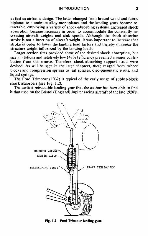
Larger-section tires provided some of the desired shock absorption, but size limitations and relatively low (47%)efficiency prevented a major contri- bution from this source. Therefore, shock-absorbing support struts were devised. As will be seen in the later chapters, these ranged from rubber blocks and compression springs to leaf springs, oleo-pneumatic struts, and liquid springs.
The Ford Trimotor (1932) is typical of the early usage of rubber-block shock absorbers (see Fig. 1.2).
The earliest retractable landing gear that the author has been able to find is that used on the Bristol (England) Jupiter racing aircraft of the late 1920's.
~.~ ~.,---.~, ,( .~--~-~
REBOUND CABLES
RUBBER DISCS
TELESCOPING STRUT S- BRAKE TENSION ROD
Fig. 1.2 Ford Trimotor landing gear.
4 AIRCRAFT LANDING GEAR DESIGN
SCREWS
, EO
Fig. 1.3 Retraction system on Curtiss Export Hawk IIIC.
In the United States, Lockheed's Model 8D Altair, which first flew in 1930, had a fully retractable landing gear and Boeing was certainly in the vanguard with their partially retracted gear on the YIB-9 bomber (1931). The Grum- man FF-1 fighter of 1932 had the wheels pulled up into the fuselage side and the Douglas DC-I had a retracted gear in 1933. However, only one of those aircraft was ever built. Then, in 1934 retractable gears were used on two types of production commercial transport aircraft~the Douglas DC-2 and the Boeing 247-D.
Figure 1.3 shows the method used to retract the gear on one of those early types~the Curtiss Export Hawk IIIC. It is a relatively simple system em- ploying hand-cranked screwjacks to pull the top of the oleo strut upward into its stored position.
It should be noted, however, that until World War II most aircraft had fixed landing gears, often with exotic-looking spats to reduce drag. The Gee Bee Super-Sportster of 1932 and Wiley Post's Lockheed Winnie Mae are typical examples and are illustrated in Fig. 1.4. One of the methods of providing shock absorption on a "spatted" landing gear is illustrated in Fig. 1.5: the leg is pivoted near the fuselage skin and the load is reacted through a lever into an oleo strut with a surrounding coil spring to provide rebound forces.
By the time World War II began, almost all of the operational fighters and bombers had retractable landing gears. There were a few notable exceptions, such as the Fairey Swordfish torpedo bomber that did so much damage to the battleship Bismarck, and the Gloster Gladiator biplane fighter~three of which (named Faith, Hope, and Charity) fought off daily bomber forma- tions over Malta. The Junkers-87 Stuka had a fixed gear, as did the basic trainers used by the U.S. Air Force (Army Air Force in those days) and Royal Air Force. Some U.S. Navy aircraft such as the Vought-Sikorsky Kingfisher also had fixed landing gears.
Since World War II, landing gear design has progressed in all areas: tire design has moved through many stages and radials are now on the threshold of general acceptance; brake materials such as beryllium and carbon have been developed; skid control systems are now being digitized with fiberoptic controls; super-high-strength steels and stress-corrosion-resistant aluminum alloys have become available; the intricacies of highly efficient shock absorp- tion are better understood; and detail design has made major strides.
INTRODUCTION 5
a) Lockheed Winnie Mae.
b) Gee Bee Super-Sportster.
Fig. 1.4 Spatted landing gears.
Aircraft design has become a very sophisticated form of engineering in the last 30 years or so and the landing gear designer has had to keep pace. He is constantly faced with achieving a satisfactory compromise between the sometimes conflicting demands of structures engineers, aerodynamicists, runway designers, and operational personnel. Transport aircraft are consid- erably heavier than they used to be---the Boeing 747 is more than twice as heavy as the 707-320C and nearly 28 times as heavy as the DC-3. So, larger landing gears are required and, to meet the requirements of the airframe designers and aerodynamicists, they must somehow be stowed in areas that have a minimum effect on the basic airframe structure and aircraft drag. Runway designers insist that high-density operations of these heavy aircraft not break up their runways. Military customers even want them to land on bare soil!
The Lockheed C-5A main landing gear is a typical example of design sophistication in meeting all of the various requirements imposed upon it.
PIVOT ~.~
#_.___
REBOUND SPRING
OLEO
• %
Fig. 1.5 Curtiss P-6E shock absorption.
Illustrated in Fig. 1.6, the most noticeable feature is its unique six-wheel bogie--an arrangement devised to maximize its flotation on bare soil by spreading the load over a wide area and avoiding, as much as possible, tires following in the same ruts. Many other unusual features were incorporated, however, to meet the severe requirements. It has a double-acting shock absorber to improve capabilities on a rough field; it has a kneeling system to lower the fuselage so that the cargo floor is a 5 ft (approximately) above the
6 AIRCRAFT LANDING GEAR DESIGN
Fig. 1.6 Lockheed C-5A main landing gear.
INTRODUCTION 7
ground; and it has a crosswind positioning system that rotates the bogies 20 deg left or right to enable the aircraft to land in a severe crosswind without a last-minute correction of the fuselage heading. Finally, it has an in-flight tire-deflation system to lower tire pressures to a preset level to maximize flotation before landing on a bare soil field.
As landing gear design proceeds toward the 21st century, carbon brakes are becoming fashionable, radial tires are being used on several aircraft to provide many benefits that will be described in later chapters, composite materials are being tested for landing gear applications, shock absorbers are reaching high efficiencies and can tolerate increased levels of airfield rough- ness, and worldwide standards are gaining recognition for the determination and reporting of airfield strengths.
1.3 LANDING GEAR TYPES
Landing gears are generally categorized by the number of wheels and their pattern. Figure 1.7 illustrates the basic types. This terminology is rapidly gaining worldwide acceptance. For instance, the USAF/USN Enroute Sup- plements define the strength of a given field as T-50/TT-100, indicating that the airfield is cleared to accept aircraft weighing 50,000 lb with a twin-wheel gear or 100,000 Ib with a twin-tandem gear.
There are also hybrid arrangements such as the 12-wheel arrangement
SINGLE CESSNA PIPER S-3A C-2A
CD
TWIN (DUAL)
B 727 B 737
DUAL TWIN (TWIN TWIN)
DH TRIDENT C-5A NOSE
TANDEM C-130 TRIPLE
SR-71
TWIN TANDEM (DUAL TANDEM)
B 707 B 747 L-1011 DC-8
CDC~
TWIN TRICYCLE (TWIN DELTA TANDEM)
C-5A
TRI-TWIN TANDEM
C~ c~
DUAL TWIN TANDEM B-58
Fig. 1.7 Standard landing gear types.
8 AIRCRAFT LANDING GEAR DESIGN
Fig. 1.8 TU-144 main landing gear.
Fig. 1.9 Track-type gear.
Fig. 1.10 Bonmartini gear.
INTRODUCTION 9
External Fuel Tanks omitted for clarity.
1 ~ iJ i J
Landing Gear Retracted
Ski Landing
C-130D and LC-130F only
Wheel Landing
Fig. I.I 1 Ski-C-130 gear.
used on the Soviet TU-144 supersonic transport depicted in Fig. 1.8 and the track gears that were tested on the Fairchild Packet, Boeing B-50, and Convair B-36--the latter is illustrated in Fig. 1.9. The objectives of the track gear were to reduce the weight and size attributable to the tires and to improve flotation by having a larger contact area.
Track gears did have higher flotation by keeping the contact pressures as low as 30 psi, but there was no weight reduction. In fact, aircraft weight was increased by about 1.8% (1.78% on the Packet and 1.87% on the B-36). Maintainability and reliability were also degraded substantially because of the complicated mechanism (multiple shock absorbers in the track bogie), low bearing life, low belt life, and high spin-up loads.
10 AIRCRAFT LANDING GEAR DESIGN
Fig. 1.12 LA-4 air cushion gear.
The Italian Bonmartini track gear was also tested successfully, but it too was heavier than a conventional gear. It used a pneumatic belt to encompass the two wheels; see Fig. 1.10.
Various types of skids and skis have been devised to replace conventional gears. The purpose of the skis is, obviously, to enable operation on snow; the Lockheed C-130R is an example of a large contemporary aircraft so equipped. As Fig. 1.11 shows, it has two configurations: one in which the wheels protrude below the skis for takeoff from conventional runways and one in which the skis are lowered below the wheels for a snow landing.
Usage of skids during and after World War II has been an endeavor to reduce the landing gear weight below the normal 3-6% of gross weight and, to a great extent, this has been accomplished. However, in most cases, the aircraft must use a trolley beneath the skids for takeoff, with the trolley being retrieved after the aircraft has left it.
Although this book is not intended to discuss the intricacies of skids and skis, for the sake of completeness some design details are included in later chapters.
Air cushion systems are another type of unconventional gear, which have been pioneered by Bell-Textron in the United States. The LA-4 was their first venture; it was a small aircraft (Fig. 1.12) that operated sucessfully on plowed ground, over tree stumps up to 6 in. high, over 3 ft wide ditches, on soft muddy ground, and over both sand and water. Further details of this and other systems, including the ACLS Buffalo, are also provided in later chapters.
1.4 DATA SOURCES Although this book defines the principles and practices of landing gear
design, the reader should be aware of many sources of i,Jormation that provide detailed recommendations, requirements, and/or lessons learned.
The Society of Automotive Engineers (SAE), through its A-5 Aerospace Landing Gear Systems Committee, has developed many Aerospace Informa- tion Reports, Recommended Practices, and Standards (AIR, ARP, AS) in this field. A list of those cited in this volume is included in Chapter 15.
INTRODUCTION 11
Military specifications are issued by the U.S. Department of Defense and civilian specifications by the Federal Aviation Agency. The British Civil Airworthiness Requirements (BCAR) are issued by the British Civil Avia- tion Authority. Those cited here are also included in Chapter 15.
Details of other references are given at the end of each chapter, as appropriate.
2 THE DESIGN PROCESS
2.1 C O M P O N E N T S OF LANDING GEAR DESIGN
The landing gear has been described as "the essential intermediary be- tween the aeroplane and catastrophe" (Ref. 1, p. 323). In support of this definition, landing gear design is considered to include the following items:
1) Forward and aft landing gears. 2) Tail bumpers. 3) Wing tip (or outer wing) gears. 4) Arresting hooks. 5) Jacking, mooring, and towing attachments. 6) Landing gear doors and their operating equipment. 7) Holdback installations. 8) Electrical and hydraulic equipment up to the interface point with
airframe-mounted equipment. 9) Layouts to show ground clearances at various aircraft attitudes and
with varying degrees of strut/tire inflation. 10) Layouts to show catapulting and arresting attitudes. 11) Calculations to show compatibility with airfield surfaces (sometimes
accomplished by special groups).
2.2 DEVELOPMENT OF FIRST CONCEPTS
Like the aircraft itself, the first concepts of a landing gear are usually prepared long before the establishment of a formal contract. Marketing organizations determine that there is a need for a new or modified aircraft. This may be the result of market surveys, discussions with potential cus- tomers, or close attention to deliberations being made by various airlines or military organizations. The marketing and preliminary design departments then cross-pollinate their thoughts, establish what they consider to be the basic requirements, and begin to prepare basic concepts.
From this point onward, it may be weeks, months, or even several years before a Request for Proposal (RFP), or its commercial equivalent, is issued by the customer; the time alloted to proposal preparation may be anywhere from 30 days to several months. Since the proposal preparation time may be extremely short, the advantages of extensive preproposal activity are obvious.
As an example, the following is a very brief summary of Lockheed C-5A activities up to first flight:
1) October 1961: U.S. Air Force issued a Qualitative Operational Re- quirement for a C-133 replacement.
13
14 AIRCRAFT LANDING GEAR DESIGN
A . . . . A
a) Lambda wing.
!
c) Canard.
_ _L__ 0 ~0 ~ 0
. . . . ,
b) High wing.
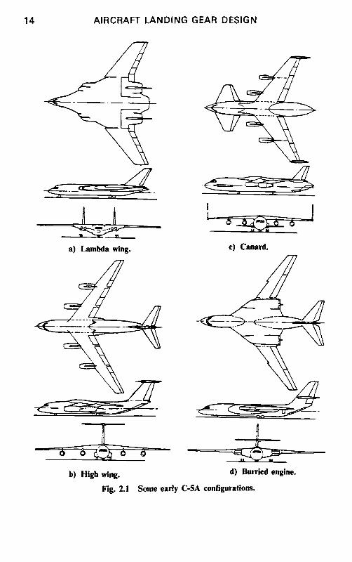
Fig. 2.1
~ , _.
d) Burried engine.
Some early C-5A configurations.
THE DESIGN PROCESS 15
2) October 1961 to April 1964: preconcept formulation phase. During this time, the USAF issued the Specific Operational Requirement (SOR) defining payloads, performance, powerplant desires, reliability, maintain- ability, availability, and details of preferred loading methods and cargo compartment size.
3) April 1964: Lockheed "froze" their initial design. 4) May 1964 to December 1964: concept formulation phase. 5) December 1964: RFP issued for project definition phase. 6) December 1964 to October 1965: project definition phase. 7) April 1965: proposal submitted (36 volumes, 7766 pages). 8) December 1965: Lockheed awarded C-5A contract. 9) June 1966: Preliminary Design Review conducted.
10) August 1967: Critical Design Review conducted. I 1) June 1968: first flight. Similar time spans are encountered on current fighter and bomber aircraft;
even commercial aircraft are not entirely immune to lengthy concept formu- lation periods. For example, serious design work on the Boeing 757/767 series started in 1973. 2 Even without the cumbersome governmental deci- sion-making systems, it took eight years from concept definition to first flight and another two years to initial deliveries of this commercial aircraft.
In the conceptual phase, the landing gear designer is often faced with a very wide variety of configurations. On the C-5A, low, high, variable-sweep, canard, and modified-delta wing configurations were considered, all with their own particular landing gear problems. Some of these configurations are depicted in Fig. 2.1. At the same time, the aircraft gross weight fluctuated between 550,000-750,000 lb, so the main landing gears ranged from a 4- wheel bogie on each side to configurations having up to 16 wheels per side. Needless to say, there is no point at this stage in trying to define any details, but flotation and tire/wheel/brake sizing are given serious consideration. This procedure is described in the next chapter.
2.3 PRELIMINARY DESIGN
Throughout the entire design process, from the development of first con- cepts through to production configurations, it is extremely important that complete documentation be maintained. For each aircraft configuration, there should be, at the very minimum, a listing of its assumed weights and geometric data in the landing gear files~and the designer should have a summary attached to it to show the basic essentials of the gear. The depth to which that summary is given depends upon the seriousness of that particu- lar configuration and/or the complexity or uniqueness of the landing gear involved.
The objectives in the preliminary design phase can be summarized as follows:
I) In the concept formulation phase, the landing gear location and the number and size of the wheels is determined. The former is, at this time, a function of center-of-gravity location and general structural arrangement. The number and size of wheels is dependent upon the weight of the aircraft, braking requirements, and, if specified, the flotation requirement.
16 AIRCRAFT LANDING GEAR DESIGN
2) In the project definition phase, the general configuration of the aircraft has been decided and the preliminary design activity becomes more analyti- cal and more detailed. Proposal preparation usually occurs at the end of this phase and a concerted effort must be made to provide as much detail and credibility as possible. The objective of the proposal is to sell the product; to do that, the customer must be convinced that every facet of the proposed aircraft is what he wants and that it is better than any competitor's product--hence, the need for detail and analysis to dispel any argument concerning its capability.
Figure 2.2 illustrates the preliminary design activity and the factors to be recognized. Note that, in the early phases, the landing gear designer may be called upon to influence the requirements in the RFP. For instance, in one project, the flotation requirement was established after an analysis had been
STATEMENT'"'i~OF ,, M A R K E T I N G
REQU,!REMENTSI . . . . . CUSTOMER
~ ANALYSIS - ,
I LOCATION STRUCT. LAYOUT FORMULATION ¢ TYPE FLOTATION REQ.
STUO,E, 1 i REQUEST J INFLUENCING / ~ FOR
[ DEFIN TION J ;'- LAYOUT PRELIM STRESS
i CONCEPT FREEZE
1 ! . _
I " I TRADEOFF PROPOSAL STUDIES
i
PRELIM LOADS
I TIRES, ] A/C WT r., SPEEDS WHEELS, BRAKE ENERGY BRAKES LOADS |
FLOTATION I A/C WT 8 CG ANALYSIS
1 BASIC / AIRFRAME STRUCT
KINEMATI CSJ
I
CONCEPT
i i KNEELING SPECIAL ~-1 CROSSWIND
FEATURESJ SELF-JACKING WATER/GRAVEL DEFLECTION
Fig. 2.2 Preliminary design activity.
THE DESIGN PROCESS 17
made of many landing gear configurations and flotation was then related to cost. The partial results of this analysis are shown in Fig. 2.3.
In another project, it was determined that an already-available landing gear (with minor modifications) was ideally suited to the new aircraft and, because of cost considerations, this became a driver in the design, precluding substantial deviation from that concept.
Referring to Fig. 2.2, landing gear activity in the concept formulation phase must recognize that there will probably be a number of widely varying aircraft concepts and that only a brief analysis is required for each one. As
6.4i
6 .3
' I v~ 6.0 O u
>.
,<
0
5.5
5.4
DEVELOPMENT, PROCUREMENT AND 10 YEAR OPERATING COSTS 200 PLANE FORCE
. . . . , .,
57~ - . . . . ~ . .
"9 / X LB l J
,, L i ¢~
, , , , , , i i , _ i
59
TAKEOFF GROSS WEIGHT
GEAa oesmNs )
. . , . ,~
. . . . . .,i I ....... i i,i ii 7' I ~ y ~ T~KEOF~ G~O~S';,EtGPT' 1 --3~ 2 7
P
V .......... 1 ..... 0 20O 4OO o00 8OO IO(X).
GEAR CAPABILITY - PASSES ON A SUPPORT AREA AIRFIELD
Fig. 2.3 Flotation vs cost (development, procurement, and 10 year operating costs of 200 plane force).
18 AIRCRAFT LANDING GEAR DESIGN
a minimum, the gear designer must know the aircraft weight and its range of center-of-gravity (c.g.) position. From this, the options for wheel numbers and sizes can be determined, e.g., two large tires or four smaller tires at the end of a shock strut.
These options will be reviewed to see how they match the airframe struc- ture and the flotation requirements (if any). Cost, weight, availability, and overall complexity are other factors to consider in the evaluation of options.
Landing gear location and length are determined by the c.g. location, tail-down angle requirements to suit takeoff and landing attitudes, tipover, and general airframe configuration. Flotation is checked for the various wheel sizes, using rigid, flexible, and bare soil rules as applicable. As noted above, this inevitably results in a small tradeoff study to determine the most cost-effective arrangement.
During this phase, there is very often considerable discussion with the prospective customer who is trying to formulate the RFP and the results of various tradeoff studies may be used to modify the original requirements. Once the RFP has been issued to the competitors, informal discussions with the customer come to an end. Questions and the resulting discussion are allowed at the Bidders Conference that takes place shortly after issuance of the RFP, but all competitors are present and questions must, therefore, be carefully worded (usually in writing) to avoid revealing one's ideas or con- cerns to the competition.
In the subsequent project definition phase, there is an urgency to freeze the design concept quickly. The best overall aircraft concept is selected and the landing gear design becomes more detailed. The continuing aircraft weight and c.g. analysis (and subsequent loads derivation) allows the designer to refine the gear location and gear loads. Based upon the defined sink rates, the approximate strokes are determined at the main gear and nose gear and, from a rough layout, the landing gear dimensions and sizes are established. A layout is then prepared to evaluate, and in particular to document, the tail-down angles, turnover angle, and clearances to deflected surfaces, engine nacelles, and propellers (if used) with various conditions of strut and tire infla tio n/defl a tion.
Tire, wheel, and brake vendors are brought in at this point. It is possible that a new tire should be developed for the aircraft or plies added to an existing tire, both of which may be a subject of vendor negotiation. If the aircraft is carrier-based, the cable-crossing and catapult requirements would also be discussed. The matching of tire and wheel size to brake size is another important activity. To address this subject adequately, the takeoff load/ speed/time data, plus dynamic taxi loads and landing loads, should be avail- able, as well as the takeoff speed profile used for any brake kinetic energy calculations. The relative size, cost, and weight of steel, beryllium, and car- bon brakes would be evaluated at this timewalthough beryllium now seems to be fading out of the picture in favor of carbon.
With tire sizes, wheel arrangements, loads, and c.g. range being deter- mined, the flotation calculations are recycled. The methods used are de- scribed in later chapters. Airfield roughness requirements (if any) are also evaluated at this time.
THE DESIGN PROCESS 19
The basic kinematics of the landing gear demand a great deal of ingenuity on the part of the designer. It involves the retraction, extension, and locking systems with due consideration to emergency conditions, including free-fall. As will be seen later, this involves a wide variety of possible systems, ranging from simple up-and-down motion to systems that rotate the entire strut about its axis while, at the same time, properly positioning the bogie. In all cases, the objective is to retract the gear into a cavity that has the least effect on basic airframe structure and also to minimize any external contour changes that might increase aircraft drag.
The steering concept is a fundamental part of the nose gear design and it must be determined before proposal preparation. Figure 2.4 illustrates the four most common types and notes the limitations of push-pull actuators. However, the latter are still the most common type of steering mechanism.
The peculiar requirements imposed on the C-5A were discussed previ- ously; Fig. 2.2 lists four such requirements: kneeling, crosswind positioning, self-jacking, and deflection of water or gravel. The first two are good candi- dates for any large transport, although crosswind positioning is very debat- able. Self-jacking refers to the ability to change tires without having to use j acks~a definite attribute for a military aircraft that has flat tires after landing at a remote austere base. Water and/or gravel deflection is some- times required to prevent water or gravel sprayed from the nose wheel being ingested in the engines~this is usually accomplished by chine treads on the
F-ZERO / ~os~ TION / <
2 i LEARA NC 0
'., C ~ x . ' ~ . MOMENT ARM c) Rotary actuator.
a) Push-pull actuator. '~ ~'~ s
d) Multiplying linkage.
b) Rack and pinion.
Fig. 2.4 Common types of steering systems.
20 AIRCRAFT LANDING GEAR DESIGN
tires or by deflector plates attached to the nose gear. Other special features could include in-flight tire deflation, ability to land on extremely soft sur- faces, or ability to land on extremely rough surfacesmpossibly with tree stumps or bomb craters.
Tradeoff studies have been mentioned previously in this chapter and a number of these are appropriate in the project definition phase. They should be fully documented and kept on file. Some examples are
l) Number and size of tires vs cost, weight, and flotation. 2) Location of main gear (wing, nacelle, or fuselage) vs cost, weight, and
performance. 3) Brake material selection. 4) Use of auxiliary braking systems. 5) Electric vs hydraulic systems for retraction, extension, and brakes. When all of the above tasks have been completed in the project definition
phase, the concept is frozen, the proposal is written, and the next mile- stone is contract award. The customer may have been influenced by certain aspects of a competitor's proposal and, as a result, may ask for certain design changes at this pointmwith appropriate impact on cost, weight, and performance.
2.4 POSTCONTRACTUAL DESIGN
By definition, the preliminary design phase continues until the Preliminary Design Review (PDR) has been completed, although by this time the person- ncl involved may well have changed to those who arc more oriented toward project design activity. These are the engineers who are better acquainted with design details such as tolerances, surface finishes, current fastener types, and anticorrosivc measures.
For military aircraft, the PDR must be scheduled prior to starting the manufacture of parts. During a PDR, the engineers describe the design to the customer, using sketches, block diagrams, concept drawings, and informal documentation. The customer determines that the design meets the specifica- tion requirements.
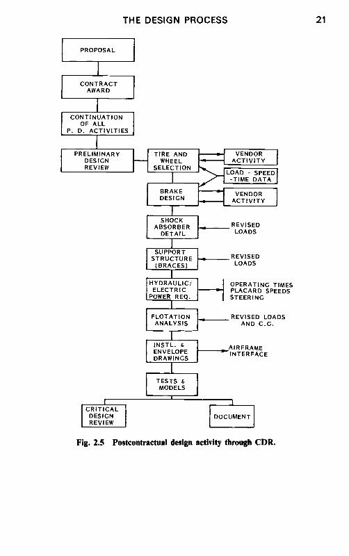
From this point until the Critical Design Review (CDR), the design is refined in every detail so that it can be finalized and the parts manufactured. A diagram for the work involved is provided in Fig. 2.5.
Prior to the CDR, the following tasks arc performed: 1) Tire and wheel selection or design is concluded, load/speed/time data
revised, and vendors established. I f there arc any peculiar requirements that the tire has not met, compliance is accomplished at this point. This could include, for instance, passage over deck arresting cables or step bumps.
2) Brake energy requirements arc updated, vendors selected, and the de- sign is finalized. If other deceleration devices, such as drag chutes, arc used on the aircraft, then calculations arc made to determine the decelerations attributable to each device.
3) Shock absorber details and support structure are sized to be compat- ible with the revised loads.
4) Electrical and hydraulic power requirements are defined for retraction,
T H E D E S I G N P R O C E S S 21
PROPOSAL
I
CONTRACT AWARD
! C'0~T,NUAT,ON ]
OF ALL I e. D. AiTIV~T,!ES I
i ' ~ ' , ~ , ~ ! DESIGN REVIEW i
TIRE AND WHEEL
SELECTION
..[ BRAKE DESIGN
I SHOCK 1
ABSORBER DETAIL
VENDOR ACTIVITY I
"",,~ LOAD - SPEED ~__~ -TIME DATA I
I --( -VENDOR" ACTIVITY ]
~ .~__..._._ REVISED LOADS
i SUPPORT
STRUCTURE ------ - - - (BRACES)
. I' HYDRAULIC/
ELECTRIC pOWER REQ.
! L
FLOTATION ANALYSIS
I , INSTL. 8 ENVELOPE DRAWINGS
I TESTS 8 MODELS
REVISED LOADS
OPERATING TIMES PLACARD SPEEDS STEERING
L REVISED LOADS ]~ AND C.G.
L . ~ A I R F R A M E ,I - INTERFACE
f ,
CRITICAL DESIGN REVIEW
1 DOCUMENT
Fig. 2.5 Postcontractuai design activity through CDR.
22 AIRCRAFT LANDING GEAR DESIGN
extension, and steering. Operating times, placard speeds, steering angle, and steering rate are determined and turning diagrams prepared.
5) Flotation analyses are updated again to reflect changes in loading on the landing gear.
6) Installation and space envelope drawings are prepared to facilitate determination of stowed landing gear clearances and to provide appropriate information to the airframe designers. This is a primary item for inclusion in the aircraft "Basic Data Book" that should be in the course of preparation at this time.
7) Tests and models may be used in this phase to acquire confidence in the proposed design, to gain a better understanding of problem areas, to display complex kinematics, and to evaluate the locking mechanisms.
8) The entire design is then documented for presentation at the CDR. The detail design and manufacture of the landing gear (or parts thereof)
may be subcontracted to one of several companies that specialize in those parts. This practice varies considerably--some aircraft companies design and build their own gears, some design the gears and have the shock struts built by a specialist company, some ask these companies to undertake all of the detail design and manufacture, and some bring in the specialists during the project definition phase. Typical examples of these specialist companies are Cleveland Pneumatic Co. and Menasco in the United States, Dowty Rotol in England and Canada, and Messier-Hispano-Bugatti in France.
The work involved in this phase includes detail design of the parts for production, system schematics, system installations, assembly drawings, in- stallation drawings, loads analysis, power analysis (hydraulic and electrical), tests, and procurement activity. Forging and casting drawings are usually completed first because of the long lead times needed. Working mockups (full scale) are sometimes employed to prove the kinematics and structural clearances and to facilitate hydraulic routing. Analyses are conducted to evaluate shimmy, dynamic response to airfield roughness, and fatigue and damage tolerances.
Various tests are conducted before first flight. During the design phase, photoelastic tests are often used to show areas of high stress concentration and to modify the design accordingly. Static structural tests measure the deflections and spring rate of the gear under load and also confirm its structural integrity. Drop tests are employed to verify shock absorber efficiency and to modify metering pin/orifice sizes to improve that efficiency if necessary. Shock strut proof pressure and leak tests are conducted and overall fit, function, and endurance tests are performed.
Procurement activity involves such items as wheels, tires, brakes, skid control, actuators, miscellaneous valves and fittings, position switches, as well as the basic landing gears themselves if they are being designed and/or built by a subcontractor. The normal procedure here is to prepare specifica- tions and vendor drawings to which competing vendors can respond. These responses are then analyzed and rated to select vendors, who, in many cases, must then provide Qualification Test Procedures for approval by the air- frame manufacturer. When the parts have been built, they are tested by the vendor, who then submits a Qualification Test Report for approval. This
THE DESIGN PROCESS 23
ensures that all of the contractor-specified requirements have been met and full documentation is available to prove it.
Other reports that should be completed before first flight are the failure modes and effects analysis (FMEA) and reliability and maintainability analyses. The FMEA is particularly important in that it evaluates the effects of the failure of any part in the overall landing gear system to determine its effect on the aircraft. Since this analysis may uncover some deficiencies that had been overlooked, its timing should be such that design changes can be made without affecting the first flight schedule.
Reliability and maintainability analyses have been required in the last 20 years or so in recognition of a growing demand for increased mission readiness and improved economics. Life cycle costs and durability are be- coming more and more important. Evidence must be produced to show how measures have been taken to minimize maintenance man-hours per flight hour.
2.5 AIR VEHICLE TEST
Despite all of the analyses, tests, and mock-ups conducted in the design phase, there are still tests to be conducted after the landing gears and systems have been installed on the aircraft. It is surprising how many problems still occurmalthough they are usually easily correctable.
Prior to flight test, tests are made to retract and extend the gear a number of times, with the aircraft on jacks. Initially, the retraction rate is lowered so that clearances can be checked in every area while the gear slowly proceeds to its up and locked position. The doors are often disconnected in the first tests so that there is adequate room to examine the clearances. After the low-rate retraction tests have been completed with doors operable, the tests are repeated at full power to verify that dynamic effects do not impair the correct functioning of the gears.
Proof loading tests are often conducted before first flight, with simulated air loads applied to the gears and doors; with these loads applied, the gear is again cycled. Apart from checking the ability to operate properly under load, the gapping of doors is examined. Aerodynamic suction forces tend to pull the doors outward and, if this is severe enough, the air forces penetrate the inside surfaces of the doors and blow them off the aircraftmhence, the need to check gapping.
Vibration tests on the aircraft determine the landing gear spring rate and natural frequency. The test results are then compared with earlier analyses to verify system stability under the complete spectrum of anticipated opera- tional conditions.
During taxi tests, the normal and emergency brake systems are evaluated along with the skid control and steering system. Stop distances are compared with predictions and the aircraft is maneuvered to examine steering and damping with normal and emergency systems. Shimmy tests are also conducted.
Demonstrations are conducted to show how towing, jacking, and mooring requirements have been met and, then, with the aircraft on jacks, a thorough


![Landing Gear Accessories - goldlinequalityparts.com€¦ · 12 Landing Gear Accessories Landing Gear Accessories 13 [254.0mm] 10.00" [254.0mm] 10.00" [111.3mm] 4.38" [304.8mm] 12.00"](https://static.documents.pub/doc/80x56/5f42201687106b11477aac9b/landing-gear-accessories-12-landing-gear-accessories-landing-gear-accessories.jpg)


