Patent applied for. AIRE-VOLVE TWIN FANS (AVT/AVTCP) Direct Drive, Run & Standby Fans for indoor use Installation and Maintenance 1 08. 03. 18. Leaflet Number 671565 The EMC Directive 2014/30/EU The Low Voltage Directive 2014/35/EU 1.0 Introduction Units are rectangular in section and have circular rigid spigots at each end. Four matching mounting feet are supplied with the unit. Units 1 - 6 incorporate a full size access panel fitted to the bottom face which is fully detachable for inspection purposes. The underside access panel can be slid in either direction with- out removal, if required, see section 4.0. Units 7 - 9 incorporate a split access panel fitted to the bottom face which is fully detachable for inspection purposes. Each split access panel can be moved and opened individually and slid in either direction without removal, if required, see section 4.1. The unit shall be double skinned with 35mm infil panels and shall be manufactured from heavy gauge, corrosion resistant Aluzinc steel, internally lined with acoustic material. Fully detachable panels for maintenance/service and manometer test points. The fan should be with an ‘inline assembly’, positioned in series for optimum performance. The models are coded as follows: 2.0 Handling Handle the units carefully to avoid damage and distortion. If mechanical aids are used to lift the unit, spreaders should be employed and positioned so as to prevent the slings, webbing etc. making contact with the casing. 3.0 Installation The installation must be carried out by competent personnel in accordance with the appropriate authority and conforming to all statutory and governing regulations. The units are supplied for installation into In-line ductwork (internal) applications only. The method of mounting used is the total responsibility of the installer. Note: The units can be mounted in any attitude. 1. Surface mounting utilising four matching mounting feet (see fig. 1). Note: The mounting feet can be employed in surface or suspended applications. 2. Suspended with drop-rods from the ceiling or in the ceiling void using four A.V. mounting feet supplied, with access panel positioned for underside access (see fig. 2 and 3). 3. Vertical wall mounting (sizes 1-6 only) utilising hanging wall brackets and hinges (see fig. 4). Vertical Mounting Kit Code: AVT(1-6)-VK. Units should always be positioned with sufficient space to allow the access panel to extend forward (see fig. 10). The unit has an external case side mounted control module/ terminal box and is supplied ready for connection into the electrical supply. The control is mounted on the side of the unit as standard but it’s position can be changed to the other side of the unit if required, see page 12 (fixings by others). As an option, an umbilical cord can be purchased for remote mounting up to 1m away, as shown in fig. 4a. Umbilical Cord Kit Code: AVT-CK. All ductwork connections must be airtight to prevent loss of performance. Fig. 2 Typical ceiling void installation (units 1 - 6). INDOOR USE ONLY Code descriptions 1. Aire-Volve Twin Fan range 2. Constant Pressure option 3. Case sizes 1 to 9 AVT - CP 1 | || 1 2 3 Fig. 1 General view of a typical unit (1 - 6) with four mounting feet employed for surface mounting and showing top access. Nuaire: A Trading Division of Polypipe Limited Western Industrial Estate Caerphilly United Kingdom CF83 1NA T: 029 2088 5911 F: 029 2088 7033 E: [email protected]W: www.nuaire.co.uk
Transcript
Patent applied for.
AIRE-VOLVE TWIN FANS(AVT/AVTCP) Direct Drive, Run & Standby Fans for indoor use
Installation and Maintenance
1 08. 03. 18. Leaflet Number 671565
The EMC Directive 2014/30/EU The Low Voltage Directive 2014/35/EU
1.0 IntroductionUnits are rectangular in section and have circular rigid spigotsat each end.
Four matching mounting feet are supplied with the unit.
Units 1 - 6 incorporate a full size access panel fitted to the bottom face which is fully detachable for inspection purposes.The underside access panel can be slid in either direction with-out removal, if required, see section 4.0.Units 7 - 9 incorporate a split access panel fitted to the bottomface which is fully detachable for inspection purposes. Eachsplit access panel can be moved and opened individually and slidin either direction without removal, if required, see section 4.1.
The unit shall be double skinned with 35mm infil panels and shallbe manufactured from heavy gauge, corrosion resistant Aluzincsteel, internally lined with acoustic material. Fully detachable panels for maintenance/service and manometertest points.
The fan should be with an ‘inline assembly’, positioned in series foroptimum performance.
The models are coded as follows:
2.0 HandlingHandle the units carefully to avoid damage and distortion. If mechanical aids are used to lift the unit, spreaders should beemployed and positioned so as to prevent the slings, webbingetc. making contact with the casing.
3.0 InstallationThe installation must be carried out by competent personnelin accordance with the appropriate authority and conformingto all statutory and governing regulations.
The units are supplied for installation into In-line ductwork(internal) applications only. The method of mounting used is the total responsibility of the installer.
Note: The units can be mounted in any attitude.
1. Surface mounting utilising four matching mounting feet (see fig. 1). Note: The mounting feet can be employed in surface or suspended applications.
2. Suspended with drop-rods from the ceiling or in the ceiling void using four A.V. mounting feet supplied, with access panel positioned for underside access (see fig. 2 and 3).
Units should always be positioned with sufficient space toallow the access panel to extend forward (see fig. 10).
The unit has an external case side mounted control module/ terminal box and is supplied ready for connection into the electrical supply. The control is mounted on the side of the unitas standard but it’s position can be changed to the other side of the unit if required, see page 12 (fixings by others).
As an option, an umbilical cord can be purchased for remotemounting up to 1m away, as shown in fig. 4a. Umbilical Cord KitCode: AVT-CK.
All ductwork connections must be airtight to prevent loss ofperformance.
Fig. 4a and 4b. Typical vertical wall installation with 4 wall brackets and hinges in use (units 1 - 6). This option allows the accessdoor to be opened from the front, rather than sliding open as in all other options. Vertical Mounting Kit Code: AVT-VK.
3 08. 03. 18. Leaflet Number 671565
Installation and Maintenance AIRE-VOLVE Direct Drive Indoor Twin Fans
WARNING: AV mounts must only be subjected to compressional forces and MUST NOT be used in a configuration that places these parts under
tension or shear force.
Dimensions (mm) & Weights
Code A B Max. supporting
weight (Kg)
NAV1 30 50 20
NAV2 40 75 80
NAV3 40 75 180
NAV4 40 75 260
NAV5 40 75 130
NAV6 50 100 320
Note: Fans using size NAV 6 upwardsrequire supporting steelwork to bedesigned (by others) for suspended applications.
Rubber Type
A
B
B
A
Figure 6a. NAV 1 to NAV 5 (Resilient Rubber)
Figure 6b. NAV 6 (Resilient Rubber)
Nuaire Limited Western Industrial Estate Caerphilly CF83 1NA United Kingdom www.nuaire.co.uk
AV mounts should not be fitted to a fan/silencer assembly unless there are flexibleconnectors fitted between the assembly and associated duct work. AV mounts should beinstalled with the matched mounting feet andpositioned such that they carry an equal proportion of the assembly weight. This isparticularly important where fans andsilencers are installed on suspension rods.
Figure 6c. NAV 1 to NAV 5 (Resilient Rubber) Correct suspended configuration.
Figure 6d. NAV 1 to NAV 5 (Resilient Rubber)Correct floor mounted configuration.
Figure 6e. NAV 1 to NAV 5 (Resilient Rubber) Correct suspended configuration.
Figure 6f. NAV 1 to NAV 5 (Resilient Rubber)
INCORRECT SUSPENDED INSTALLATION
4
4
4
8
3.2 Anti-Vibration /Resilient MountsSuspension rods / fixing screws are not supplied. Note that the large round washersincluded in the resilient mounting kits are for fitting above or below the resilient mountingas required to safeguard the installationagainst break-up of, or damage to, a mount-ing. In the event of a resilient mounting failurethe washer will support the weight of the unit.
Anti-vibration mounting kits are availablein both rubber and spring type, the correctselection and type employed will depend onthe accurate calculation of the weight ofthe assembly to be supported.
8
4
Installation and Maintenance AIRE-VOLVE Direct Drive Indoor Twin Fans
08. 03. 18. Leaflet Number 671565
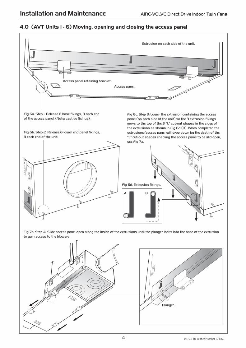
4.0 (AVT Units 1 - 6) Moving, opening and closing the access panel
Fig 6a. Step 1: Release 6 base fixings, 3 each endof the access panel. (Note: captive fixings).
Fig 6b. Step 2: Release 6 lower end panel fixings, 3 each end of the unit.
Fig 6c. Step 3: Lower the extrusion containing the accesspanel (on each side of the unit) so the 3 extrusion fixingsmove to the top of the 3 “L” cut-out shapes in the sides ofthe extrusions as shown in Fig 6d (B). When completed theextrusions/access panel will drop down by the depth of the“L” cut-out shapes enabling the access panel to be slid open,see Fig 7a.
Fig 6d. Extrusion fixings.
A B
Extrusion on each side of the unit.
Access panel retaining bracket.
Fig 7a. Step 4: Slide access panel open along the inside of the extrusions until the plunger locks into the base of the extrusionto gain access to the blowers.
Plunger.
Access panel.
Installation and Maintenance AIRE-VOLVE Direct Drive Indoor Twin Fans
5 08. 03. 18. Leaflet Number 671565
4.0 (AVT Units 1 - 6) Moving, opening and closing the access panel cont.
Fig 7c. Step 6: Lift the extrusion (on each side of the unit) containing the access panel to its original position so thatthe 3 extrusion fixings move back to the bottom of the “L”cut-out shapes as shown in (A) Fig 7d and lock.
Fig 7d. Extrusion fixings.
A B
Fig 7e. Step 7: To complete closure of the access panel and make secure, retighten 6 lower end panel fixings, 3 each end of theunit and the 6 base fixings, 3 each end of the access panel.
Fig 7B. Step 5: To close the access panel, ensure retaining brackets are aligned then push plungers back into the extrusionbase to release access panel, before sliding back to its original aligned position.
6
Installation and Maintenance AIRE-VOLVE Direct Drive Indoor Twin Fans
08. 03. 18. Leaflet Number 671565
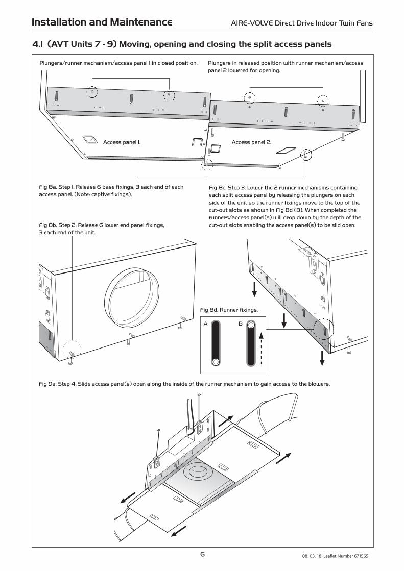
4.1 (AVT Units 7 - 9) Moving, opening and closing the split access panels
Fig 8a. Step 1: Release 6 base fixings, 3 each end of eachaccess panel. (Note: captive fixings).
Fig 8b. Step 2: Release 6 lower end panel fixings, 3 each end of the unit.
Fig 8c. Step 3: Lower the 2 runner mechanisms containingeach split access panel by releasing the plungers on eachside of the unit so the runner fixings move to the top of thecut-out slots as shown in Fig 8d (B). When completed therunners/access panel(s) will drop down by the depth of thecut-out slots enabling the access panel(s) to be slid open.
Fig 8d. Runner fixings.
A B
Access panel 1.
Fig 9a. Step 4: Slide access panel(s) open along the inside of the runner mechanism to gain access to the blowers.
Access panel 2.
Plungers/runner mechanism/access panel 1 in closed position. Plungers in released position with runner mechanism/accesspanel 2 lowered for opening.
Installation and Maintenance AIRE-VOLVE Direct Drive Indoor Twin Fans
7 08. 03. 18. Leaflet Number 671565
4.1 (AVT Units 7 - 9) Moving, opening and closing the split access panels cont.
Fig 9c. Step 6: Lift the runner mechanism (on each side of theunit) containing the access panel(s) to the original positionsso that the runner fixings move back to the bottom of thecut-out slots as shown in (A) Fig 9d and re-set the plungersin the closed position.
Fig 9d. Runner fixings.
A B
Fig 9B. Step 5: To close the access panel(s) slide the access panel(s) back to the original aligned position.
Fig 9e. Step 7: To complete closure of the access panel(s) and make secure, retighten 6 lower end panel fixings, 3 each end ofthe unit and then the 6 base fixings, 3 each end of each access panel.
8 08. 03. 18. Leaflet Number 671565
Installation and Maintenance AIRE-VOLVE Direct Drive Indoor Twin Fans
Side viewEnd view
Plan view
X = Clearance
40
B A X = Clearance
D
C
X = Clearance
X = Clearance X = Clearance
Dim A+ spigot X =
Fan length Dim B Spigot Weight ClearanceCode A (100mm) B + control C D (dia) (kg) required FLC
AVT1 931 1031 544 648 250 200 46 430 0.75
AVT2 968 1068 543 647 285 200 48 430 1.4
AVT3 1186 1286 681 785 334 250 67 555 1.35
AVT4 1229 1329 681 785 376 315 68 655 3.1
AVT4L 1531 1631 827 931 401 315 99 880 1.1
AVT5 1531 1631 827 931 433 315 102 880 3.5
AVT6 1729 1829 921 1025 545 400 153 830 2.9
AVT7 1892 1992 1019 1123 575 400 179 655 3.5
AVT8 2238 2338 1244 1348 615 500 267 635 3.2
AVT9 2238 2338 1244 1348 615 500 244 635 1.85
5.0 Dimensions Aire-Volve units and clearance required (mm)
Matched silencers with double walled aluzinc construction and35mm infill acoustic lining provides the best acoustic solution.
Easy fit matching silencers with simple integral brackets can beeasily incorporated into existing drop rod systems helping toreduce install time on site.
Fan Size Silencer A B C Weight Code Code (kg)
AVT1 Standard AVT1-MSS 1000 544 260 32
Long AVT1-MSL 1500 544 260 45
AVT2 Standard AVT2-MSS 1000 543 286 32
Long AVT2-MSL 1500 543 286 45
AVT3 Standard AVT3-MSS 1000 681 332 39
Long AVT3-MSL 1500 681 332 56
AVT4 Standard AVT4-MSS 1000 681 374 39
Long AVT4-MSL 1500 681 374 56
AVT4L Standard AVT4L-MSS 1000 827 401 42
Long AVT4L-MSL 1500 827 401 61
AVT5 Standard AVT5-MSS 1000 827 481 44
Long AVT5-MSL 1500 827 481 65
AVT6 Standard AVT6-MSS 1000 921 552 64
Long AVT6-MSL 1500 921 552 89
AVT7 Standard AVT7-MSS 1000 1019 653 41
Long AVT7-MSL 1500 1019 653 98
AVT8 Standard AVT8-MSS 1000 1244 753 83
Long AVT8-MSL 1500 1244 753 114
AVT9 Standard AVT9-MSS 1000 1244 774 92
Long AVT9-MSL 1500 1244 774 125
A
B
C
Fig. 11. Dimensions (mm).
5.1 Matched silencers, dimensions (mm) & weights
Fig. 10. Once assembled units should always be positioned with sufficient free space adjacent to the unit to allow for access for future inspection,maintenance, component service, repair and replacement. Note: The access panels also require opening clearance to operate, and the figures are indicatedin Fig 10. and the table below (X = clearancerequired).
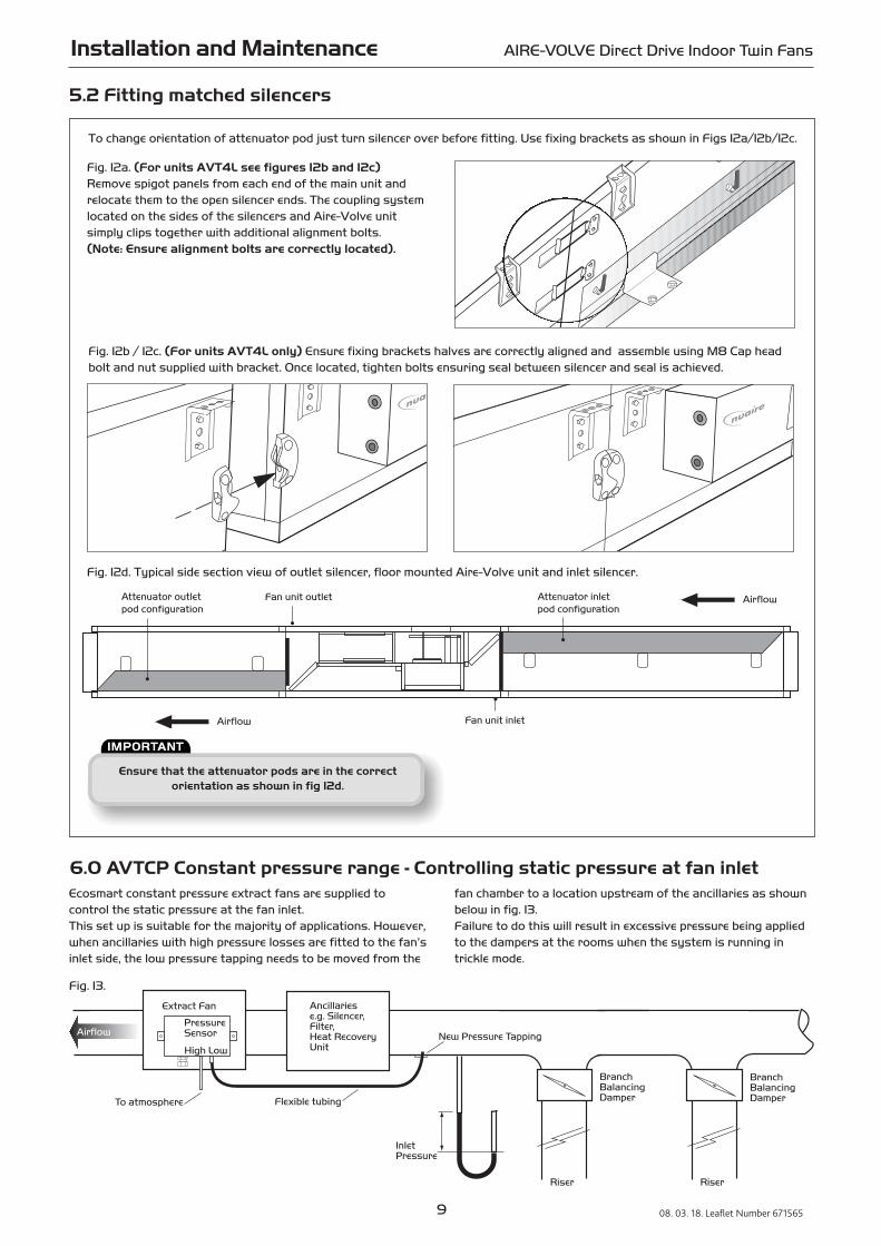
Ensure that the attenuator pods are in the correct orientation as shown in fig 12d.
9 08. 03. 18. Leaflet Number 671565
Installation and Maintenance AIRE-VOLVE Direct Drive Indoor Twin Fans
Airflow
Fan unit outlet
Fan unit inlet
Attenuator inlet pod configuration
Attenuator outlet pod configuration
Airflow
Fig. 12d. Typical side section view of outlet silencer, floor mounted Aire-Volve unit and inlet silencer.
5.2 Fitting matched silencers
6.0 AVTCP Constant pressure range - Controlling static pressure at fan inlet
Riser
Ancillariese.g. Silencer,Filter,Heat RecoveryUnit
Riser
InletPressure
Branch Balancing Damper
Branch Balancing Damper
Extract Fan
To atmosphere
PressureSensor
High Low
Flexible tubing
New Pressure TappingAirflow
Ecosmart constant pressure extract fans are supplied to control the static pressure at the fan inlet. This set up is suitable for the majority of applications. However,when ancillaries with high pressure losses are fitted to the fan’sinlet side, the low pressure tapping needs to be moved from the
fan chamber to a location upstream of the ancillaries as shownbelow in fig. 13.Failure to do this will result in excessive pressure being appliedto the dampers at the rooms when the system is running intrickle mode.
Fig. 13.
To change orientation of attenuator pod just turn silencer over before fitting. Use fixing brackets as shown in Figs 12a/12b/12c.
Fig. 12b / 12c. (For units AVT4L only) Ensure fixing brackets halves are correctly aligned and assemble using M8 Cap headbolt and nut supplied with bracket. Once located, tighten bolts ensuring seal between silencer and seal is achieved.
Fig. 12a. (For units AVT4L see figures 12b and 12c)Remove spigot panels from each end of the main unit andrelocate them to the open silencer ends. The coupling systemlocated on the sides of the silencers and Aire-Volve unit simply clips together with additional alignment bolts. (Note: Ensure alignment bolts are correctly located).
7.0 Electrical detailBecause the run and start currents depend upon the duty andassociated ductwork of an individual unit, run currents will be exceeded if the unit is operated with its cover removed. It is therefore recommended that the unit is not run for prolonged periods in this condition.
7.1 Testing after installationEnsure that the fan unit and any specified controls are fittedsecurely according to the instructions.
Switch on the mains supply. push the test button to run eachfan and check that they run satisfactorily.
If a switched live signal is used, activate this signal and checkthat the fan runs. De-activate the switched live signal and checkthe run-on-time; adjust if necessary.
Adjust the set point of any sensors and PIR; check that theyfunction correctly. Adjust the maximum and minimum airflow (if required) by following the commissioning procedures.
8.0 Wiring Connectionsa) Mains connections
Mains cables should be suitably sized and terminated at terminals shown on the appropriate diagram.
b) Control Connections
Net - the 4 IDC plug-in connectors are provided for the connection of compatible sensors, manual controls and for linking the fans together under a common control. If more than4 connections are required, the junction box (product code ES-JB) should be used (see data cable installation).
c) Switched Live (SL) terminal
A signal of 100-230V a.c. will activate the fan from either its offstate or trickle state (see setting to work-trickle switch).When the SL is disconnected the fan will over-run (see setting towork-timer adjustment).
Do not take this signal from an isolating transformer.
d) Damper connections
OP - 230V 50Hz 1A max supply to open the damper
CL - 230V 50Hz 1A max supply to close the damper
N - Neutral supply to damper
RET - 230V ac return signal from the damper limit switch indicates the damper has reached its operating position. If the return signal is not present, the fan will wait for 1 minutebefore starting.
Note: If a damper is not fitted, connect a link wire from OP to RET. This will cancel the delay.
e) Volt Free Relay Contacts
f) Data cable installation
A 4-core SELV data cable is used to connect devices such as sensors to the fan and for interconnecting multiple fan units.
Do not run data cable in the same conduit as the mainscables and ensure there is a 50mm separation between the datacable and other cables.
The maximum cable run between any two devices is 300m whenit is installed in accordance with the instructions. Please note that the total data cable length used in any systemmust be less than 1000m. Keep the number of cable joints to aminimum to ensure the best data transmission efficiency between devices + 50m or less for ES-LCD.
g) Maximum number of devices
The maximum number of devices (including fans) that can be connected together via the data cable is 32, irrespective of their functions.
Isolation - Before commencing work make surethat the unit, switched live and Nuaire control are
electrically isolated from the mains supply.
10 08. 03. 18. Leaflet Number 671565
Installation and Maintenance AIRE-VOLVE Direct Drive Indoor Twin Fans
Figure 15.
Figure 16a. Driveopen/Spring close.
Figure 16b. Drive open/Drive close.
Figure 17.
Figure 14. ‘Net’ connection for Ecosmart devices.
11 08. 03. 18. Leaflet Number 671565
Installation and Maintenance AIRE-VOLVE Direct Drive Indoor Twin Fans
Note: All inter-connections between circuit boards, blowers and sensors are made at the factory. These diagrams only show the essential field wiring points for clarity. *Remove link wire if switched live signal, an enabler or BMS signal is connected.
Figure 19. The Control Module
Volt Free Contact RUN signal 5A resistive
0.5A inductiveVolt Free Contact FAULT signal
Connections to Damper
RU
N F
AU
LT
N
L
SL
DP
CL
N
RET
400V 3ph 50Hz supply
Remove this link wire if a switched live signal is connected to terminal SLNOTE: Also remove link if a BMS is connected.Also remove link if an enabling device is connected in the 'NET'
Switch live signal(if required)
NET connections for ECOSMART devices
No user connections
CO2 sensorconnections
0 +ve signalfrom BMS
EC
OS
MA
RT
NE
T
N L1 L2 L3
Ribbon cableto commissioningbox
N L1 L2 L3
Fig. 18a Wiring for single phase units AVT 1 to 8.
Fig. 20. Commissioning panel details. Note: A Commissioning Procedure document (leaflet No. 671153)is available on request from the Nuaire Technical Library Tel: 02920 885911.
Figure 21.
For good EMC engineering practice, any sensor or low voltage data cables should not be placed within
50mm of mains cables or placed on the same cable tray or conduit as mains cables.
9.0 Using the test button (see fig. 20).
The test button allows the individual blowers within the unit tobe checked for its operation. If the fan is running already, pressthe button once to stop the fan, press again to switch on thestandby fan, press again to stop and so on.
Note that the fan will return to normal operation after 30 seconds.
10.0 LED indication (see fig. 20).
PWR GREEN: Power on & OK. RED: To much power is taken by peripherals or there is a short circuit in the net cable. Check the cable and use a junction box (ES-JB) to connect some of the peripherals.
Standby LED on when fan is not running.Fan 1 GREEN: Fan 1 is running, RED: Fan 1 faulty.Fan 2 GREEN: Fan 2 is running, RED: Fan 2 faulty.Heating* Not applicable. See note.Cooling* Not applicable. See note.Fault LED on when a fault is present on unit.Frost* Not applicable. See note.Tx LED on when the controller is transmitting data.Rx LED on when the controller is receiving data.
* Note that the control panel is common to all the Ecosmartproducts and will have indicators for functions that are notavailable in this particular fan. However these indicators willnot be illuminated.
11.0 BMS input signalsOther low voltage cables e.g. BMS signal
Follow the basic principle (as f, page 9). Keep the cable run asshort as possible, less than 50 metres.
BMS input signals
The BMS connection is made with a plug-in connector via the socket (See figure 14). To ensure the connection is made only by suitably qualified and authorised personnel the plug is not supplied. It is available from R S Components, Part No. 403-875 or Farnell, Part No. 963-021.
The system’s response to a 0-10V dc BMS signal is given in thetable below.
Note the BMS signal will override any sensors and user controlconnected in the system. The voltage tolerance is +/_ 125mVand is measured at the fans terminal.
Ventilation mode Cooling mode* Heating mode*
Local control 0.00 - -
OFF / trickle 0.25 - -
Speed 1 0.50 0.75 1.00
Speed 2 1.50 1.75 2.00
Speed 3 2.50 2.75 3.00
Speed 4 3.50 3.75 4.00
Speed 5 4.50 4.75 5.00
Speed 6 5.50 5.75 6.00
Speed 7 6.50 6.75 7.00
Speed 8 7.50 7.75 8.00
Speed 9 8.50 8.75 9.00
Speed 10 9.50 9.75 10.00
* Only available on relevant unit.
12.0 Setting the airflowSetting the maximum air flow
i) Ensure the power supply is switched off and that a link wire isconnected from the supply L to the SL terminal. Unplug all itemsconnected to the ‘Net‘ connectors.
ii) Switch on the power supply.Note: Ensure unit cover is securely attached.
iii) Wait for the fan to complete its self-test operation.
iv) Remove the cover of the units external commissioning box.Measure the airflow using standard commissioning instrumentsat a suitable point in the ductwork. If adjustment is required,rotate the pot marked ‘MAX’ to obtain the desired airflow.
Setting the minimum trickle airflow (nominally 40%)
i) Repeat the same procedure as for maximum airflow abovebut without the link wire between supply L and SL terminal.Ensure the trickle switch is in the ‘ON’ position.The adjustment must be made on the pot marked ‘Min’.
ii) Note that the minimum setting (nominally 40%) must bebelow the maximum setting, otherwise minimum setting willbe automatically set to be the same as the maximum.After setting the airflows, re-connect all the items disconnectedpreviously. Ensure that the cover over the mains terminals isreplaced and that the cover of the controls enclosure issecurely fastened.
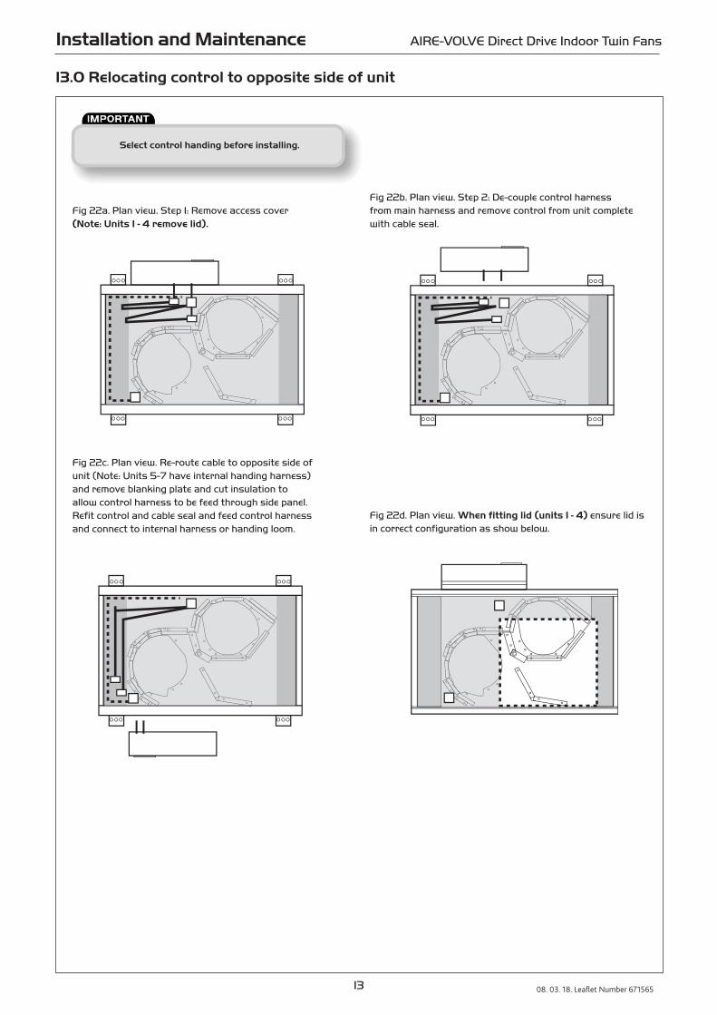
Select control handing before installing.
13 08. 03. 18. Leaflet Number 671565
Installation and Maintenance AIRE-VOLVE Direct Drive Indoor Twin Fans
13.0 Relocating control to opposite side of unit
Fig 22a. Plan view. Step 1: Remove access cover (Note: Units 1 - 4 remove lid).
Fig 22b. Plan view. Step 2: De-couple control harnessfrom main harness and remove control from unit completewith cable seal.
Fig 22c. Plan view. Re-route cable to opposite side ofunit (Note: Units 5-7 have internal handing harness) and remove blanking plate and cut insulation to allow control harness to be feed through side panel. Refit control and cable seal and feed control harnessand connect to internal harness or handing loom.
Fig 22d. Plan view. When fitting lid (units 1 - 4) ensure lid isin correct configuration as show below.
14 08. 03. 18. Leaflet Number 671565
Installation and Maintenance AIRE-VOLVE Direct Drive Indoor Twin Fans
Isolation - Before commencing work make surethat the unit, switched live and Nuaire control are
electrically isolated from the mains supply.
14.0 Maintenance
The first maintenance should be carried out three months aftercommissioning and thereafter at twelve monthly intervals.These intervals may need to be shortened if the unit is operatingin adverse environmental conditions, or in heavily polluted air.Note: failure to maintain the unit as recommended will invalidate the warranty.
LubricationMotors are fitted with sealed for life bearings and do not requireany lubrication.
General cleaning and inspectionClean and inspect the exterior of the fan unit and associatedcontrols etc. Remove the access panel from the fan unit. Inspect and, if necessary, clean the fan and motor assembliesand the interior of the case. If the unit is heavily soiled it may be more convenient to remove the fan/motor assemblies.
Check that the shutters are free to move smoothly and that theyseal the appropriate fan outlet effectively.
Clean and inspect each fan and motor assembly as follows; taking care not to damage, distort or disturb the balance of the impeller.
a) Lightly brush away dirt and dust, paying particularattention to any build up at the motor ventilating slots.If necessary, carefully remove with a blade or scraper.
b) Stubborn dirt at the impeller may be carefully removedwith a stiff nylon brush.
c) Check all parts for security and general condition.Check that the impeller rotates freely.
Refit the assemblies to the unit (see Replacement of Parts) then replace the access covers.If Nuaire controls and or remote indicators are fitted, remove the covers and carefully clean out the interiors as necessary. Check for damage. Check security of components. Refit the access covers.
15.0 Replacement of partsThe only items of the fan units unit likely to require replacement are the fan/motor assemblies due to a failed motor or damaged impeller or damper actuator.
Remove the access cover. Disconnect the incoming wiring from the connection box (located on the fan scroll) on the particular fan/motor assembly to be removed.
Remove the fan/motor fixings completely, other than the two slotted hole fixings. Support the fan/motor assembly and loosen the slotted hole fixings. The fan/motor assembly can now be turned and withdrawn from the unit.
After replacing the faulty item, refit the fan motor/assembly using the slotted hole fixings to assist in supporting the assembly. Re-connect the wiring. Replace the access cover.
16.0 Spare partsWhen ordering spares please quote the serial number of the unit together with the part number. If the part number is not known please give a full description of the part required. The serial number will be found on the identification plate attached to the unit casing.
17.0 WarrantyThe 5 year warranty starts from the day of delivery and includes parts and labour for the first year. The remaining period covers replacement parts only.
This warranty is void if the equipment is modified without authorisation, is incorrectly applied, misused, disassembled, or not installed, commissioned and maintained in accordance with the details contained in this manual and general good practice.
The product warranty applies to the UK mainland and in accordance with Clause 14 of our Conditions of Sale. Customers purchasing from outside of the UK should contact Nuaire International Sales office for further details.
18.0 After SalesFor technical assistance or further product information, including spare parts and replacement components, please contact the After Sales Department.
Telephone 029 2085 8400
15 08. 03. 18. Leaflet Number 671565
Installation and Maintenance AIRE-VOLVE Direct Drive Indoor Twin Fans
Technical or commercial considerations may, from time to time, make it necessary to alter the design, performance and dimensions of equipment and the right is reserved to make such changes without prior notice.
To comply with EC Council Directives 2006/42/EC Machinery Directive and 2014/30/EU (EMC).
To be read in conjunction with the relevant Product Documentation (see 2.1)
1.0 GENERAL
1.1 The equipment referred to in this Declaration of Incorporation is supplied by Nuaire to be assembled into a ventilation system which may or may not include additional components.
The entire system must be considered for safety purposes and it is the responsibility of the installer to ensure that all of the equipment is installed in compliance with the manufacturers recommendations and with due regard to current legislation and codes of practice.
2.0 INFORMATION SUPPLIED WITH THE EQUIPMENT
2.1 Each item of equipment is supplied with a set of documentation which provides the information required for the safe installation and maintenance of the equipment. This may be in the form of a Data sheet and/or Installation and Maintenance instruction.
2.2 Each unit has a rating plate attached to its outer casing. The rating plate provides essential data relating to the equipment such as serial number, unit code and electrical data. Any further data that may be required will be found in the documentation. If any item is unclear or more information is required, contact Nuaire.
2.3 Where warning labels or notices are attached to the unit the instructions given must be adhered to.
3.0 TRANSPORTATION, HANDLING AND STORAGE
3.1 Care must be taken at all times to prevent damage to the equipment. Note that shock to the unit may result in the balance of the impeller being affected.
3.2 When handling the equipment, care should be taken with corners and edges and that the weight distribution within the unit is considered. Lifting gear such as slings or ropes must be arranged so as not to bear on the casing.
3.3 Equipment stored on site prior to installation should be protected from the weather and steps taken to prevent ingress of contaminants.
4.0 OPERATIONAL LIMITS
4.1 It is important that the specified operational limits for the equipment are adhered to e.g. operational air temperature, air borne contaminants and unit orientation.
4.2 Where installation accessories are supplied with the specified equipment eg. wall mounting brackets. They are to be used to support the equipment only. Other system components must have separate provision for support.
4.3 Flanges and connection spigots are provided for the purpose of joining to duct work systems. They must not be used to support the ductwork.
5.0 INSTALLATION REQUIREMENTS
In addition to the particular requirements given for the individual product, the following general requirements should be noted.
5.1 Where access to any part of equipment which moves, or can become electricallylive are not prevented by the equipment panels or by fixed installation detail (eg ducting), then guarding to the appropriate standard must be fitted.
5.2 The electrical installation of the equipment must comply with the requirements of the relevant local electrical safety regulations.
5.3 For EMC all control and sensor cables should not be placed within 50mm or on the same metal cable tray as 230V switched live, lighting or power cables and any cables not intended for use with this product.
6.0 COMMISSIONING REQUIREMENTS
6.1 General pre-commissioning checks relevant to safe operation consist of the following:
Ensure that no foreign bodies are present within the fan or casing.
Check electrical safety. e.g. Insulation and earthing.
Check guarding of system.
Check operation of Isolators/Controls.
Check fastenings for security.
6.2 Other commissioning requirements are given in the relevant product documentation.
7.0 OPERATIONAL REQUIREMENTS
7.1 Equipment access panels must be in place at all times during operation of the unit, and must be secured with the original fastenings.
7.2 If failure of the equipment occurs or is suspected then it should be taken out of service until a competent person can effect repair or examination. (Note that certain ranges of equipment are designed to detect and compensate for fan failure).
8.0 MAINTENANCE REQUIREMENTS
8.1 Specific maintenance requirements are given in the relevant product documentation.
8.2 It is important that the correct tools are used for the various tasks required.
8.3 If the access panels are to be removed for any reason the electrical supply to the unit must be isolated.
8.4 A minium period of two minutes should be allowed after electrical disconnection before access panels are removed. This will allow the impeller to come to rest.
NB: Care should still be taken however since airflow generated at some other point in the system can cause the impeller to “windmill” even when power is not present.
8.5 Care should be taken when removing and storing access panels in windy conditions.
INFORMATION FOR SAFE INSTALLATION, OPERATION AND MAINTENANCE OF NUAIRE VENTILATION EQUIPMENT
DECLARATION OF INCORPORATION AND INFORMATION FOR SAFE INSTALLATION, OPERATION AND MAINTENANCE
We declare that the machinery named below is intended to be assembledwith other components to constitute a system of machinery. All parts except for moving parts requiring the correct installation of safetyguards comply with the essential requirements of the Machinery Directive.The machinery shall not be put into service until the system has been declared to be in conformity with the provisions of the EC Machinery Directive.
Designation of machinery: AIRE-VOLVE (AVT/AVTCP)
Machinery Types: Direct Drive Indoor Twin Fans
Relevant EC Council Directives: 2006/42/EC (Machinery Directive)
Applied Harmonised Standards: BS EN ISO 12100-1, BS EN ISO 12100-2, EN60204-1, BS EN ISO 9001, BS EN ISO 13857
Applied National Standards: BS848 Parts 1, 2.2 and 5
Note: All standards used were current and valid at the date of signature.
Signature of manufacture representatives:Name: Position: Date: