AIRTRONIC AIRTRONIC D2, 12 V AIRTRONIC D2, 24 V AIRTRONIC D2 OEM Heaters,12 V (Wiring goes to the right side hous- ing of the casing) and, 12 V TK Use instructions and parts based on AIRTRONIC D2 CAMPER, 12 V Order no. 25 2069 05 25 2070 05 25 2508 05 25 2440 05 25 2069 05 25 2326 05 AIRTRONIC M D4 AIRTRONIC M D4, 12 V AIRTRONIC M D4, 24 V AIRTRONIC M D4 OEM Heater, 12 V use instructions and parts based on 25 2113 05 AIRTRONIC M D4S, 12 V AIRTRONIC M D4 Camper Plus 12 V AIRTRONIC M B4, 12 V 25 2113 05 25 2114 05 25 2441 05 25 2144 05 25 2327 05 20 1812 05 20 2900 81 01 03 0H 05.2015
Transcript
AIRTRONIC
AIRTRONIC D2, 12 VAIRTRONIC D2, 24 V
AIRTRONIC D2 OEM Heaters,12 V(Wiring goes to the right side hous-ing of the casing) and, 12 V TKUse instructions and parts based on
AIRTRONIC D2 CAMPER, 12 V
Order no.
25 2069 0525 2070 05
25 2508 0525 2440 0525 2069 05
25 2326 05
AIRTRONIC M D4
AIRTRONIC M D4, 12 VAIRTRONIC M D4, 24 VAIRTRONIC M D4 OEM Heater, 12 Vuse instructions and parts based on 25 2113 05AIRTRONIC M D4S, 12 VAIRTRONIC M D4 Camper Plus 12 VAIRTRONIC M B4, 12 V
This document aims to support service technicians and end users in North America. This does not replace documentation produced by J. Eberspächer.
The installation instructions and standards described in this document are NOT APPLICABLE TO MARINE INSTALLATIONS.
This publication was correct at the time of going to print. However, Eberspaecher Inc. has a policy of continuous improvement and reserves the right to amend
Please consult a certified Eberspaecher Marine dealer for marine installation.
4
5
1
2
3
2
PLEASE NOTE!
3
PLEASE NOTE!
PLEASE NOTE!
HEATER WARNINGS
WARNING TO INSTALLER: Correct installation of this heater is necessary to ensure safe and proper operation. Read and understand this manual before attempting to install a heater.
WARINING - EXPLOSION HAZARD 1. Heater must be turned off while re-fueling. 2. Do not install heater in enclosed areas where combustible fumes may be present. 3. Do not install heaters in engine compartments of marine vessels.
WARINING - FIRE HAZARD 1. Install heater so it will maintain a minimum distance of 2” from any flammable or heat sensitive material. 2. Install the exhaust system so it will maintain a minimum distance of 2” from any flammable or heat sensitive material. 3. Ensure that the fuel system is intact and there are no leaks.
Failure to follow these instructions could cause fire resulting in serious or fatal injury.
WARINING - ASPHYXIATION HAZARD 1. Route the heater exhaust so that exhaust fumes can not enter any passenger compartments. 2. Ensure an air tight seal is maintained between the heater and mounting surface and at any exhaust connection points. 3. Ensure that heating air supply is taken from an area where poisonous gases will not be present. 4. If running exhaust components through an enclosed compartment, ensure that it is vented to the outside.
Failure to follow these instructions could cause oxygen depletion resulting in serious or fatal injury.
Direct questions to Eberspaecher:
Canada & U.S.A. 1-800-387-4800
OPERATION WITH BIO-DIESEL
AIRTRONIC D2The diesel heater is not approved for 100% Bio-Diesel. Mixtures up to 10% bio fuel (FAME) may be used.
AIRTRONIC M (D4)The diesel heater is approved for up to 100% Bio-Diesel according to the following conditions:- Bio-Diesel (FAME) according to Standard CAS NO. 67784-80-9 (or similar) in free flowing state (reduced at tempera tures below 0°C (32°F);- Operation of heater with mixtures greater then 10% is restriced during periods of temperatures below 0°C (32°F)- Maintenance schedule for Bio-Diesel mixtures greater then 10% - Heater must be run for 30min on high heat with regular diesel fuel once every 500h if mixtures above 20% are used; - Vent hole must be cleaned every 500h (twice a heating season assuming 1000h of operation annually); - Atomizing Screen must be replaced every 500h (twice a heating season assuming 1000h of operation annually).
All maintenance procedures may be performed without removing heater from vehicle.
Only one kit from the listed below is needed.
HEATING AT HIGH ALTITUDESUp to 1500 meters (4920’) - unrestricted heating operation is possible.Above 1500 meters (4920’) - heating operation is in principle possible for short periods, e.g. when crossing a mountain pass or during a brief stop. In cases of extended stays, the fuel supply at the fuel metering pump has to be adapted to high altitude conditions.
The following high altitude kits are available:P/N: 24 0222 00 00 00 - 12V only (Contains high altitude fuel pump)
orP/N: 20 2900 70 00 07 - 12V or 24V (Contains high altitude compensator,no extra fuel pump needed)
orP/N: 22 1000 33 22 00 - 12V or 24V (Only works with Airtronic Heaters that have “H-Kit” on the factory label)
MARINE CONCIDERATIONS• Follow marine manual for installation requirements (separete document)• Gasoline (B4) heaters must not be installed in ingene compartment.• Diesel or Gasoline (petrol) heaters must not be installed in engine compartment of gasoline (petrol) boats.
4
5
1
2
3This manual aims to support the service company installing the heater and to provide the user with all important information about the heater.The manual has been divided into 5 chapters to make it easier to find the corresponding information quickly.
INTRODUCTION Here you will find important introductory information about installation of the heater and about the structure of the manual. Product information Here you will find information about the scope of supply, the technical data and the dimensions of the heater.
PRODUCT INFORMATION Here you will find information about the scope of supply, the technical data and the dimensions of the heater.
INSTALLATION PROCEDURES Here you will find important information and instructions referring to installation of the heater.
HEATER OPERATION Here you will find information about the operation and function of the heater.
MAINTENANCE / TROUBLESHOOTING / REPAIRS This section contains information on possible faults and malfunctions, troubleshooting, maintenance and the service hotline.
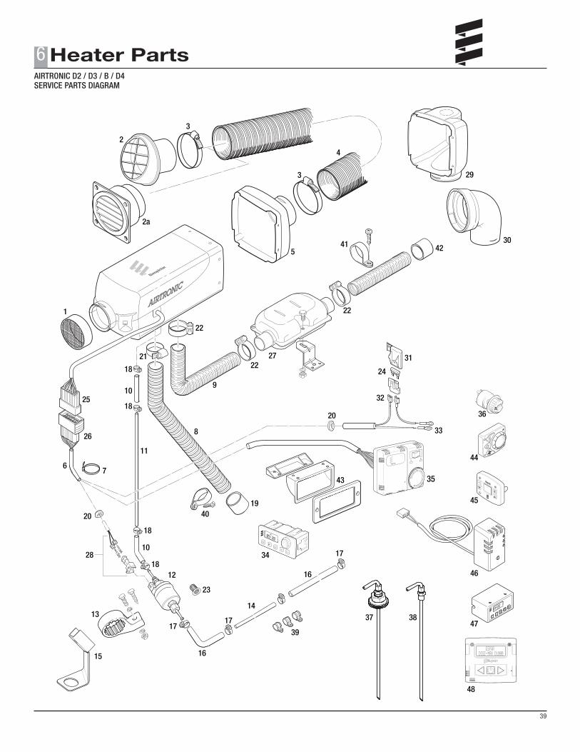
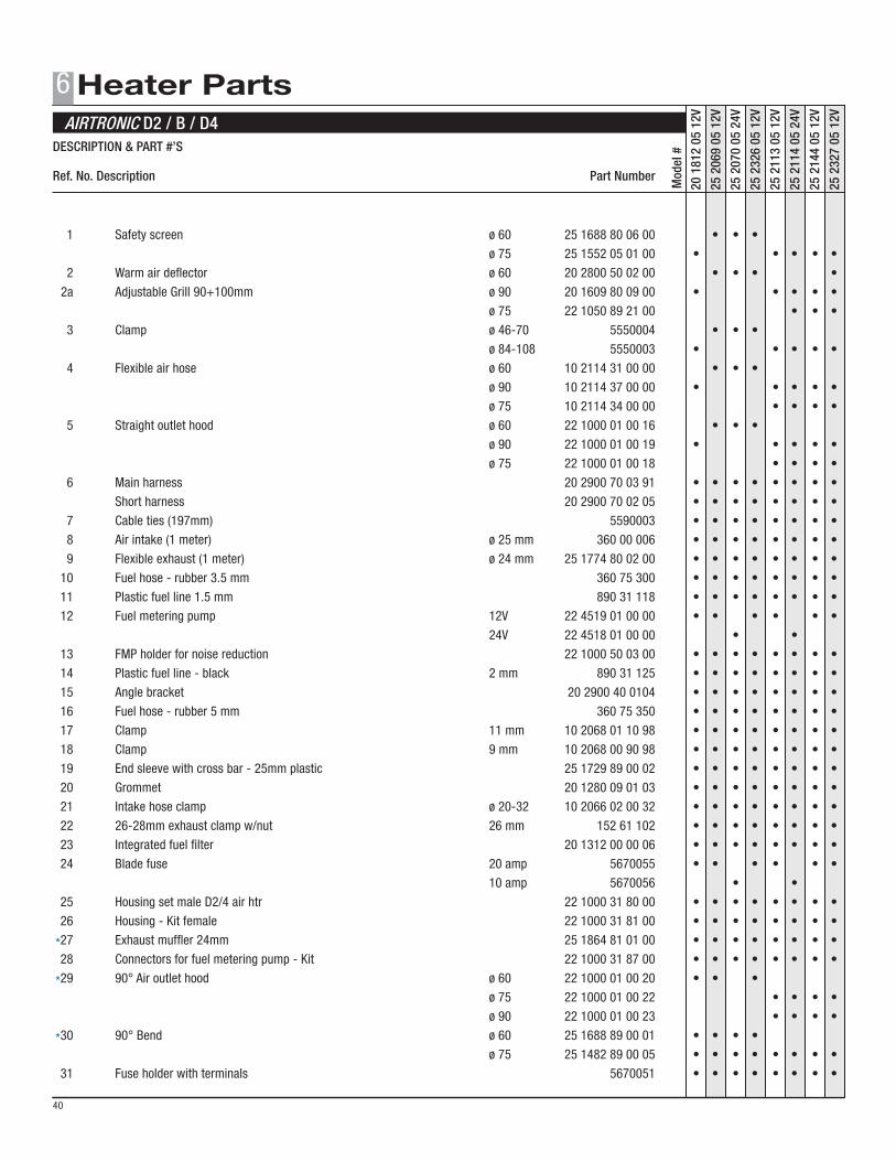
HEATER PARTS Here you will find the service parts diagrams and parts list.
CONCEPT OF THIS MANUAL
3
1
6
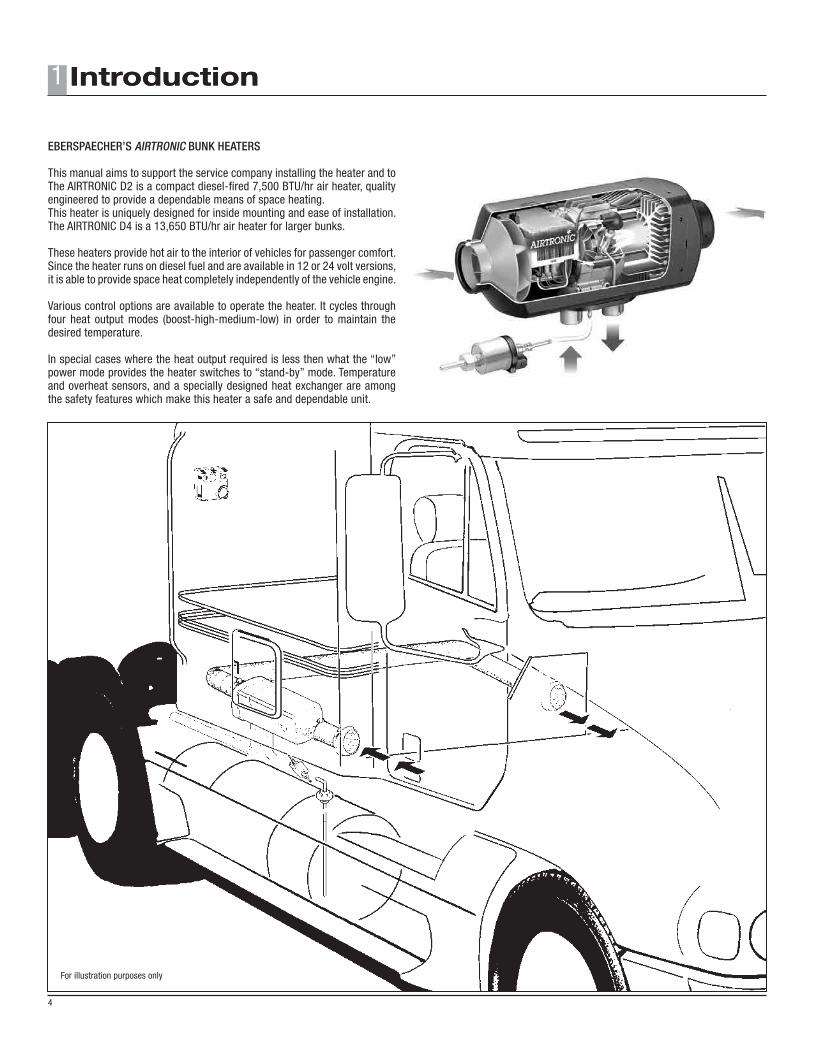
For illustration purposes only
1
4
EBERSPAECHER’S AIRTRONIC BUNK HEATERS
This manual aims to support the service company installing the heater and to The AIRTRONIC D2 is a compact diesel-fired 7,500 BTU/hr air heater, quality engineered to provide a dependable means of space heating.This heater is uniquely designed for inside mounting and ease of installation.The AIRTRONIC D4 is a 13,650 BTU/hr air heater for larger bunks.
These heaters provide hot air to the interior of vehicles for passenger comfort. Since the heater runs on diesel fuel and are available in 12 or 24 volt versions, it is able to provide space heat completely independently of the vehicle engine.
Various control options are available to operate the heater. It cycles through four heat output modes (boost-high-medium-low) in order to maintain the desired temperature.
In special cases where the heat output required is less then what the “low” power mode provides the heater switches to “stand-by” mode. Temperature and overheat sensors, and a specially designed heat exchanger are among the safety features which make this heater a safe and dependable unit.
5
2
PLEASE NOTE!PLEASE NOTE!
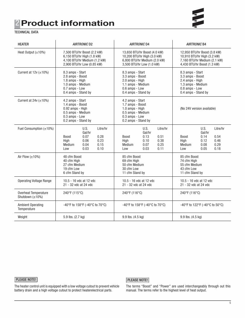
The heater control unit is equipped with a low voltage cutout to prevent vehicle battery drain and a high voltage cutout to protect heaterelectrical parts.
The terms “Boost” and “Power” are used interchangeably through out this manual. The terms refer to the highest level of heat output.
TECHNICAL DATA
HEATER AIRTRONIC D2 AIRTRONIC D4 AIRTRONIC B4 Heat Output (±10%) 7,500 BTU/hr Boost (2.2 kW) 13,650 BTU/hr Boost (4.0 kW) 12,950 BTU/hr Boost (3.8 kW) 6,150 BTU/hr High (1.8 kW) 10,200 BTU/hr High (3.0 kW) 10,910 BTU/hr High (3.2 kW) 4,100 BTU/hr Medium (1.2 kW) 6,800 BTU/hr Medium (2.0 kW) 7,160 BTU/hr Medium (2.1 kW) 2,900 BTU/hr Low (0.85 kW) 3,500 BTU/hr Low (1.0 kW) 4,430 BTU/hr Boost (1.3 kW) Current at 12v (±10%) 8.3 amps - Start 8.3 amps - Start 8.3 amps - Start 2.8 amps - Boost 3.3 amps - Boost 3.3 amps - Boost 1.8 amps - High 2.0 amps - High 2.4 amps - High 1.0 amps - Medium 1.1 amps - Medium 1.3 amps - Medium 0.7 amps - Low 0.6 amps - Low 0.8 amps - Low 0.4 amps - Stand by 0.4 amps - Stand by 0.4 amps - Stand by Current at 24v (±10%) 4.2 amps - Start 4.2 amps - Start 1.4 amps - Boost 1.7 amps - Boost 0.92 amps - High 1.0 amps - High (No 24V version available) 0.5 amps - Medium 0.5 amps - Medium 0.3 amps - Low 0.3 amps - Low 0.2 amps - Stand by 0.2 amps - Stand by Fuel Consumption (±10%) U.S. Litre/hr U.S. Litre/hr U.S. Litre/hr Gal/hr Gal/hr Gal/hr Boost 0.07 0.28 Boost 0.13 0.51 Boost 0.14 0.54 High 0.06 0.23 High 0.10 0.38 High 0.12 0.46 Medium 0.04 0.15 Medium 0.07 0.25 Medium 0.08 0.29 Low 0.03 0.10 Low 0.03 0.11 Low 0.05 0.18 Air Flow (±10%) 48 cfm Boost 85 cfm Boost 85 cfm Boost 40 cfm High 69 cfm High 74 cfm High 27 cfm Medium 50 cfm Medium 55 cfm Medium 19 cfm Low 30 cfm Low 43 cfm Low 6 cfm Stand by 11 cfm Stand by 11 cfm Stand by
Operating Voltage Range 10.5 - 16 vdc at 12 vdc 10.5 - 16 vdc at 12 vdc 10.5 - 16 vdc at 12 vdc 21 - 32 vdc at 24 vdc 21 - 32 vdc at 24 vdc 21 - 32 vdc at 24 vdc
Overheat Temperature 240°F (115°C) 240°F (116°C) 240°F (116°C) Shutdown (±10%)
Ambient Operating -40°F to 158°F (-40°C to 70°C) -40°F to 158°F (-40°C to 70°C) -40°F to 122°F (-40°C to 50°C) Temperature Weight 5.9 lbs. (2.7 kg) 9.9 lbs. (4.5 kg) 9.9 lbs. (4.5 kg)
(12.2 inches)
(4.8
inch
es)
64.5
89.5
325
122
(4.5 inches)115
44min. 174 x M6
(14.8 inches)
(5.9
inch
es)
80
105
325
150
(4.5 inches)140
44
132.5
min. 174 x M6
2
6
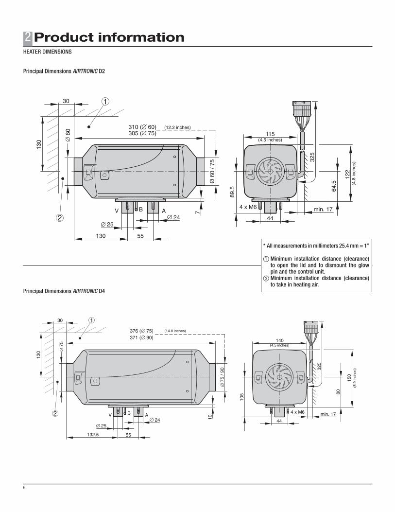
Principal Dimensions AIRTRONIC D2
Principal Dimensions AIRTRONIC D4
* All measurements in millimeters 25.4 mm = 1”
aMinimum installation distance (clearance) to open the lid and to dismount the glow pin and the control unit. bMinimum installation distance (clearance) to take in heating air.
HEATER DIMENSIONS
2
7
Espar
12
3
4
0
32
14 15 16 17
23
2019
22
18
21
13
41 5 6 7
10
12 11 8 9
FF HH
CC
EE24
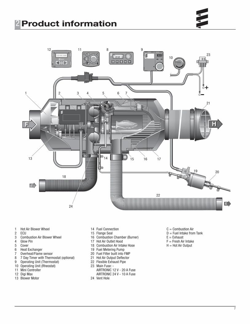
1 Hot Air Blower Wheel2 ECU3 Combustion Air Blower Wheel4 Glow Pin5 Cover6 Heat Exchanger7 Overheat/Flame sensor8 7 Day Timer with Thermostat (optional)9 Operating Unit (Thermostat)10 Operating Unit (Rheostat)11 Mini Controller12 Digi Max13 Blower Motor
14 Fuel Connection15 Flange Seal16 Combustion Chamber (Burner)17 Hot Air Outlet Hood18 Combustion Air Intake Hose19 Fuel Metering Pump20 Fuel Filter built into FMP21 Hot Air Output Deflector22 Flexible Exhaust Pipe23 Main Fuse: - AIRTRONIC 12 V - 20 A Fuse AIRTRONIC 24 V - 10 A Fuse24 Vent Hole
C = Combustion AirD = Fuel Intake from TankE = ExhaustF = Fresh Air IntakeH = Hot Air Output
Nut
Spring Washer
Cab Floor
Silicon gasket (flange)Hex Head Tek Screw
Flat washerStainless Steel PlatePlate seal
10mm
minimum10mm
minimum
3
8
PLEASE NOTE!
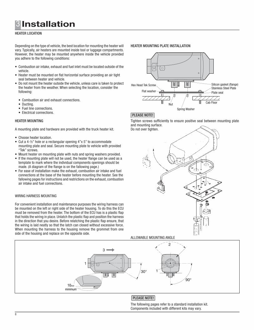
Depending on the type of vehicle, the best location for mounting the heater will vary. Typically, air heaters are mounted inside tool or luggage compartments. However, the heater may be mounted anywhere inside the vehicle provided you adhere to the following conditions:
• Combustion air intake, exhaust and fuel inlet must be located outside of the vehicle.• Heater must be mounted on flat horizontal surface providing an air tight seal between heater and vehicle.• Do not mount the heater outside the vehicle, unless care is taken to protect the heater from the weather. When selecting the location, consider the following:
• Combustion air and exhaust connections. • Ducting. • Fuel line connections. • Electrical connections.
HEATER MOUNTING
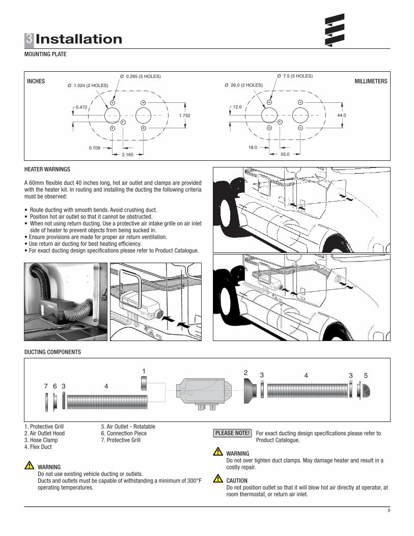
A mounting plate and hardware are provided with the truck heater kit.
• Choose heater location.• Cut a 4-½” hole or a rectangular opening 4”x 5” to accommodate mounting plate and seal. Secure mounting plate to vehicle with provided “Tek” screws.• Mount heater on mounting plate with nuts and spring washers provided.• If the mounting plate will not be used, the heater flange can be used as a template to mark where the individual components openings should be made. (A diagram of the flange is on the fallowing page.)• For ease of installation make the exhaust, combustion air intake and fuel connections at the base of the heater before mounting the heater. See the fallowing pages for instructions and restrictions on the exhaust, combustion air intake and fuel connections.
WIRING HARNESS MOUNTING
For convenient installation and maintenance purposes the wiring harness can be mounted on the left or right side of the heater housing. To do this the ECU must be removed from the heater. The bottom of the ECU has is a plastic flap that holds the wiring in place. Unlatch the plastic flap and position the harness in the direction that you desire. Before relatching the plastic flap ensure, that the wiring is laid neatly so that the latch can closed without excessive force. When mounting the harness to the housing remove the grommet from one side of the housing and replace on the opposite side.
HEATER MOUNTING PLATE INSTALLATION
Tighten screws sufficiently to ensure positive seal between mounting plate and mounting surface.Do not over tighten.
ALLOWABLE MOUNTING ANGLE
The following pages refer to a standard installation kit.Components included with different kits may vary.
HEATER LOCATION
PLEASE NOTE!
0.472
2.1650.709
Ø 1.024 (2 HOLES)
Ø 0.295 (5 HOLES)
1.732
12.0
55.018.0
Ø 26.0 (2 HOLES)
Ø 7.5 (5 HOLES)
44.0
Inches Millimeters
7 6 3 4
1 2 3 3 54
HEATER WARNINGS
A 60mm flexible duct 40 inches long, hot air outlet and clamps are provided with the heater kit. In routing and installing the ducting the following criteria must be observed:
• Route ducting with smooth bends. Avoid crushing duct.• Position hot air outlet so that it cannot be obstructed.• When not using return ducting. Use a protective air intake grille on air inlet side of heater to prevent objects from being sucked in.• Ensure provisions are made for proper air return ventilation.• Use return air ducting for best heating efficiency.• For exact ducting design specifications please refer to Product Catalogue.
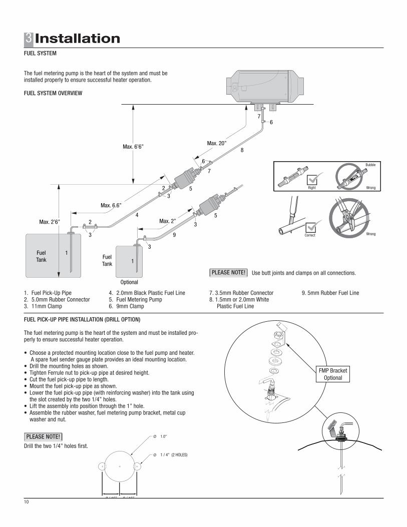
The fuel metering pump is the heart of the system and must be installed pro-perly to ensure successful heater operation.
• Choose a protected mounting location close to the fuel pump and heater. A spare fuel sender gauge plate provides an ideal mounting location.• Drill the mounting holes as shown.• Tighten Ferrule nut to pick-up pipe at desired height.• Cut the fuel pick-up pipe to length.• Mount the fuel pick-up pipe as shown.• Lower the fuel pick-up pipe (with reinforcing washer) into the tank using the slot created by the two 1/4” holes.• Lift the assembly into position through the 1” hole.• Assemble the rubber washer, fuel metering pump bracket, metal cup washer and nut.
Drill the two 1/4” holes first.
Use butt joints and clamps on all connections.
7. 3.5mm Rubber Connector 9. 5mm Rubber Fuel Line8. 1.5mm or 2.0mm White Plastic Fuel Line
FUEL SYSTEM
3
10
PLEASE NOTE!
PLEASE NOTE!
FMP Bracket Optional
Ø 1.0”
9 / 16” 9 / 16”
Ø 1 / 4” (2 HOLES)
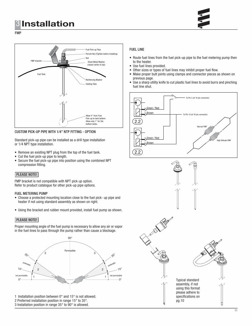
Fuel Pick-up Pipe
Ferrule Nut (Tighten before installing)
Nut
Sheet Metal Washer(raised center to top)
Reinforcing Washer
Holding Tabs
Allow 4" from FuelPick-up to tank bottom.Allow only 1" for flatbottom tanks.
Fuel Tank
FMP bracket
Permissible
not permissiblenot permissible
preferable preferable
Green / Red
To Pin 5 (of 16 pin connector)
To Pin 10 (of 16 pin connector)
Normal FMP
High Altitude FMP
Brown
Green / Red
Brown
CUSTOM PICK-UP PIPE WITH 1/4” NTP FITTING - OPTION
Standard pick-up pipe can be installed as a drill type installationor 1/4 NPT type installation.
• Remove an existing NPT plug from the top of the fuel tank.• Cut the fuel pick-up pipe to length.• Secure the fuel pick-up pipe into position using the combined NPT compression fitting.
FMP bracket is not compatible with NPT pick up option.Refer to product catalogue for other pick-up pipe options.
FUEL METERING PUMP• Choose a protected mounting location close to the fuel pick- up pipe and heater if not using standard assembly as shown on right.
• Using the bracket and rubber mount provided, install fuel pump as shown.
Proper mounting angle of the fuel pump is necessary to allow any air or vapor in the fuel lines to pass through the pump rather than cause a blockage.
1 Installation position between 0° and 15° is not allowed.2 Preferred installation position in range 15° to 35°.3 Installation position in range 35° to 90° is allowed.
FUEL LINE
• Route fuel lines from the fuel pick-up pipe to the fuel metering pump then to the heater.• Use fuel lines provided.• Other sizes or types of fuel lines may inhibit proper fuel flow.• Make proper butt joints using clamps and connector pieces as shown on previous page.• Use a sharp utility knife to cut plastic fuel lines to avoid burrs and pinching fuel line shut.
Typical standard assembly, if not using this format please adhere to specifications on pg.10
PLEASE NOTE!
FMP
11
3
PLEASE NOTE!
Espar
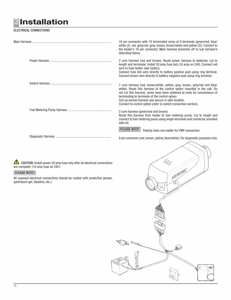
Main Harness
Fuel Metering Pump Harness
Connector for Diagnostics
Switch Harness
Thermostat
Power Harness
Fuel and holder
Main Harness ..............................................................................................
Power Harness .........................................................................
CAUTION: Install power 20 amp fuse only after all electrical connections are complete. (10 amp fuse on 24V.)
All exposed electrical connections should be coated with protective grease, (petroleum gel, Vaseline, etc.).
16 pin connector with 10 terminated wires at 8 terminals (green/red, blue/white (2), red, grey/red, grey, brown, brown/white and yellow (2)). Connect to the heater’s 16 pin connector. Main harness branches off to sub harness’s described below.
2 core harness (red and brown). Route power harness to batteries, cut to length and terminate. Install 20 amp fuse last (10 amp on 24V). Connect red wire to fuse holder near battery.Connect fuse link wire directly to battery positive post using ring terminal. Connect brown wire directly to battery negative post using ring terminal.
7 core harness (red, brown/white, yellow, grey, brown, grey/red and blue/white). Route this harness to the control option mounted in the cab. Do not cut this harness, wires have been soldered at ends for convenience of terminating to terminals of the control option.Coil up excess harness and secure in safe location.Connect to control option (refer to switch connection section).
2 core harness (green/red and brown).Route this harness from heater to fuel metering pump. Cut to length and connect to fuel metering pump using single terminals and connector provided with kit.
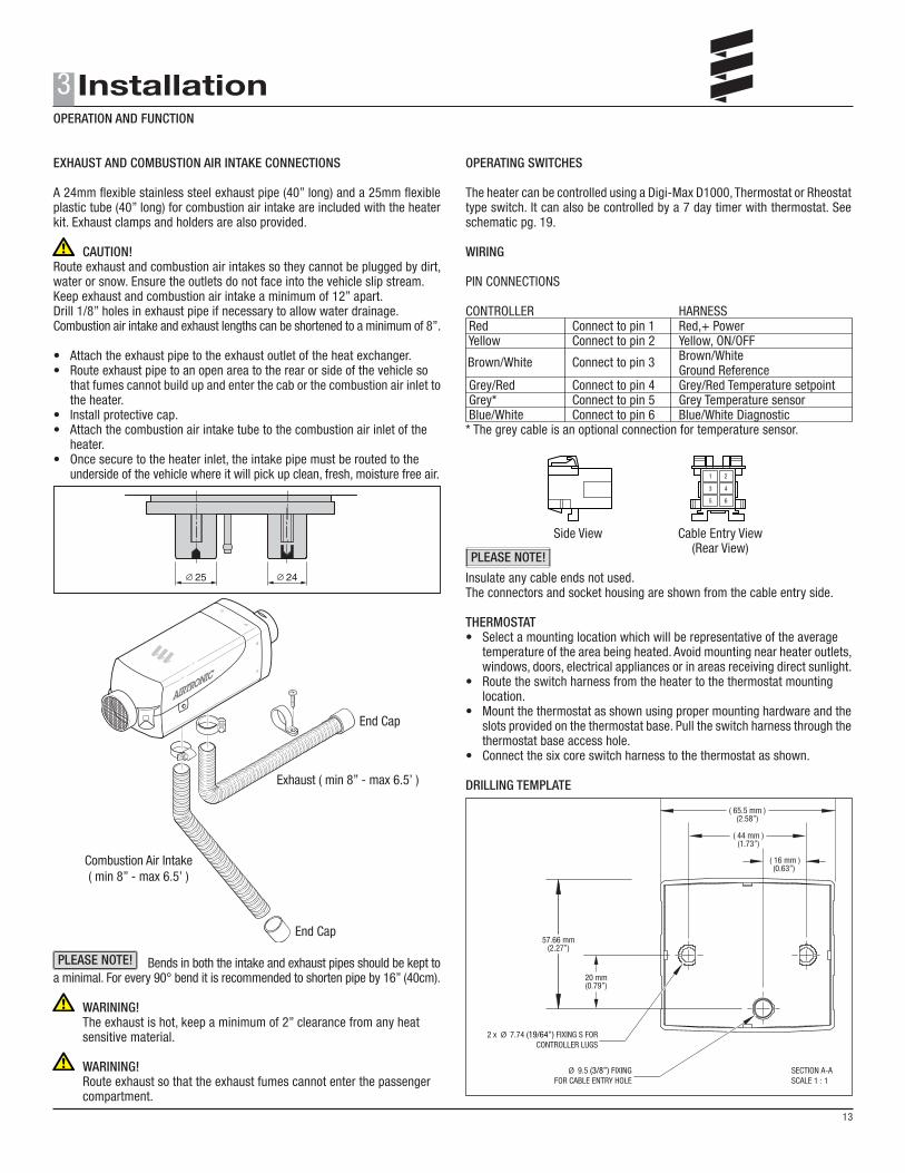
A 24mm flexible stainless steel exhaust pipe (40” long) and a 25mm flexible plastic tube (40” long) for combustion air intake are included with the heater kit. Exhaust clamps and holders are also provided.
CAUTION! Route exhaust and combustion air intakes so they cannot be plugged by dirt, water or snow. Ensure the outlets do not face into the vehicle slip stream.Keep exhaust and combustion air intake a minimum of 12” apart.Drill 1/8” holes in exhaust pipe if necessary to allow water drainage.Combustion air intake and exhaust lengths can be shortened to a minimum of 8”.
• Attach the exhaust pipe to the exhaust outlet of the heat exchanger.• Route exhaust pipe to an open area to the rear or side of the vehicle so that fumes cannot build up and enter the cab or the combustion air inlet to the heater.• Install protective cap.• Attach the combustion air intake tube to the combustion air inlet of the heater.• Once secure to the heater inlet, the intake pipe must be routed to the underside of the vehicle where it will pick up clean, fresh, moisture free air.
Bends in both the intake and exhaust pipes should be kept to a minimal. For every 90° bend it is recommended to shorten pipe by 16” (40cm).
WARINING! The exhaust is hot, keep a minimum of 2” clearance from any heat sensitive material.
WARINING! Route exhaust so that the exhaust fumes cannot enter the passenger compartment.
OPERATING SWITCHES
The heater can be controlled using a Digi-Max D1000, Thermostat or Rheostat type switch. It can also be controlled by a 7 day timer with thermostat. See schematic pg. 19.
WIRING
PIN CONNECTIONS CONTROLLER HARNESS Red Connect to pin 1 Red,+ Power Yellow Connect to pin 2 Yellow, ON/OFF Brown/White Ground Reference Grey/Red Connect to pin 4 Grey/Red Temperature setpoint Grey* Connect to pin 5 Grey Temperature sensor Blue/White Connect to pin 6 Blue/White Diagnostic * The grey cable is an optional connection for temperature sensor.
Side View Cable Entry View (Rear View)
Insulate any cable ends not used.The connectors and socket housing are shown from the cable entry side.
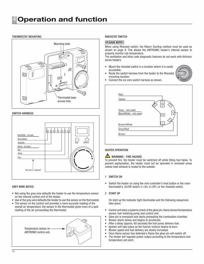
THERMOSTAT• Select a mounting location which will be representative of the average temperature of the area being heated. Avoid mounting near heater outlets, windows, doors, electrical appliances or in areas receiving direct sunlight.• Route the switch harness from the heater to the thermostat mounting location.• Mount the thermostat as shown using proper mounting hardware and the slots provided on the thermostat base. Pull the switch harness through the thermostat base access hole.• Connect the six core switch harness to the thermostat as shown.
DRILLING TEMPLATE
PLEASE NOTE!
Brown/White Connect to pin 3
SECTION A-ASCALE 1 : 1
( 44 mm )(1.73”)
( 16 mm )(0.63”)
Ø 9.5 (3/8”) FIXINGFOR CABLE ENTRY HOLE
2 x Ø 7.74 (19/64”) FIXING S FORCONTROLLER LUGS
( 65.5 mm )(2.58”)
20 mm(0.79”)
57.66 mm(2.27”)
5
96 4
310
1
2
Red
Yellow
Brown/White
Grey/Red
Brown
Grey - not usedBlue/White - not used
Brown/White
Grey/Red
Red
Yellow
Grey
1 2 3 4 5 6 T
1 0
RED GREEN
Blue/White - not used
Brown - not used
This wire is “optional”
12
3
4
0
Temperature sensor onAIRTRONIC control unit.
Mounting slots
Thermostat baseaccess hole
Mounting slots
Thermostat baseaccess hole
THERMOSTAT MOUNTING
SWITCH HARNESS
GREY WIRE NOTES:
• Not using the grey wire defaults the heater to use the temperature sensor on the internal control unit of the heater.• Use of the grey wire defaults the heater to use the sensor on the thermostat.• The sensor on the control unit provides a more accurate reading of the overall air temperature, the sensor in the thermostat gives more of a spot reading of the air surrounding the thermostat.
RHEOSTAT SWITCH
When using Rheostat switch, the Return Ducting method must be used as shown on page 9. This allows the AIRTRONIC heater’s internal sensor to properly monitor cab temperature.The ventilation and blink code diagnostic features do not work with Airtronic series heaters.
• Mount the rheostat switch in a location where it is easily accessible.• Route the switch harness from the heater to the Rheostat mounting location.• Connect the six core switch harness as shown.
HEATER OPERATION
WARINING - FIRE HAZARDTo prevent fire, the heater must be switched off while filling fuel tanks. To prevent asphyxiation, the heater must not be operated in enclosed areas unless heat exhaust is routed to the outside.
1 SWITCH ON
• Switch the heater on using the mini controller’s heat button or the room thermostat’s, On/Off switch (1=On, 0=Off ) or the rheostat switch.
2 START UP
On start up the indicator light illuminates and the following sequences take place:
• Control unit does a systems check of the glow pin, flame sensor/temperature sensor, fuel metering pump and control unit.• Glow pin is energized and starts preheating the combustion chamber.• Blower starts slowly and begins to accelerate.• After a delay (approx. 60 seconds) the fuel pump delivers fuel.• Ignition will take place as the fuel/air mixture begins to burn.• Blower speed and fuel delivery are slowly increased.• Once flame sensor has detected a flame the glow pin will switch off.• The heater will regulate power output according to the temperature and temperature set point.
4
14
PLEASE NOTE!
On/Off switch
Red operating light
12
3
4
0
LOW HIGH
Operation indicating light
Green LED indicationRed LED indicationLCD screen informationEnable/disable the heaterWhen pressed, temperature set point goes upWhen pressed, temperature set point goes down
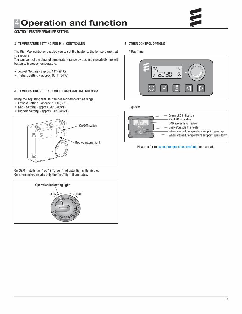
3 TEMPERATURE SETTING FOR MINI CONTROLLER
The Digi-Max controller enables you to set the heater to the temperature that you require.You can control the desired temperature range by pushing repeatedly the left button to increase temperature.
Using the adjusting dial, set the desired temperature range.• Lowest Setting - approx. 10°C (50°F)• Mid - Setting - approx. 20°C (68°F)• Highest Setting - approx. 30°C (86°F)
On OEM installs the “red” & “green” indicator lights illuminate.On aftermarket installs only the “red” light illuminates.
5 OTHER CONTROL OPTIONS
7 Day Timer
Digi-Max
Please refer to espar.eberspaecher.com/help for manuals.
CONTROLLERS TEMPERATURE SETTING
15
4
Fuel Pump
Glow Pin
Blower
STARTING PHASE RUNNING PHASE SHUT DOWN PHASE
OperatingMode
System Check Pre-heat
Pre-heat2nd. Attempt
IgnitionAttempt
IgnitionAttempt
2nd. Attempt
ControlledHeating
Off a)
On, If iddlingwithout external
temperaturesensor.
On On On On On On c) On
Off OffOffOff OffOn On On On
ON ifstopped
Off if standby mode
Off Off Off Off Off OffOn
On
OnOn On
After GlowCool
Down Stand by
1- 3 sec. a) 60 sec. d)
40 sec.120 sec.Up to
90 sec.
Up to 90 sec.
If Required
4 min.
Boost on start,Medium on
restart
Time dependenton heat
exchangertemperature
Continual Operation
until switched off by operator
or temperature control
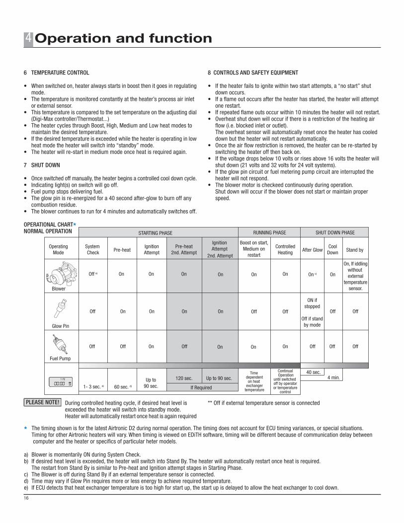
6 TEMPERATURE CONTROL
• When switched on, heater always starts in boost then it goes in regulating mode.• The temperature is monitored constantly at the heater’s process air inlet or external sensor.• This temperature is compared to the set temperature on the adjusting dial (Digi-Max controller/Thermostat...)• The heater cycles through Boost, High, Medium and Low heat modes to maintain the desired temperature.• If the desired temperature is exceeded while the heater is operating in low heat mode the heater will switch into “standby” mode.• The heater will re-start in medium mode once heat is required again.
7 SHUT DOWN
• Once switched off manually, the heater begins a controlled cool down cycle.• Indicating light(s) on switch will go off.• Fuel pump stops delivering fuel.• The glow pin is re-energized for a 40 second after-glow to burn off any combustion residue.• The blower continues to run for 4 minutes and automatically switches off.
OPERATIONAL CHART*NORMAL OPERATION
During controlled heating cycle, if desired heat level is exceeded the heater will switch into standby mode. Heater will automatically restart once heat is again required
8 CONTROLS AND SAFETY EQUIPMENT
• If the heater fails to ignite within two start attempts, a “no start” shut down occurs.• If a flame out occurs after the heater has started, the heater will attempt one restart.• If repeated flame outs occur within 10 minutes the heater will not restart.• Overheat shut down will occur if there is a restriction of the heating air flow (i.e. blocked inlet or outlet). The overheat sensor will automatically reset once the heater has cooled down but the heater will not restart automatically.• Once the air flow restriction is removed, the heater can be re-started by switching the heater off then back on.• If the voltage drops below 10 volts or rises above 16 volts the heater will shut down (21 volts and 32 volts for 24 volt systems).• If the glow pin circuit or fuel metering pump circuit are interrupted the heater will not respond.• The blower motor is checkeed continuously during operation. Shut down will occur if the blower does not start or maintain proper speed.
** Off if external temperature sensor is connected
4
16
PLEASE NOTE!
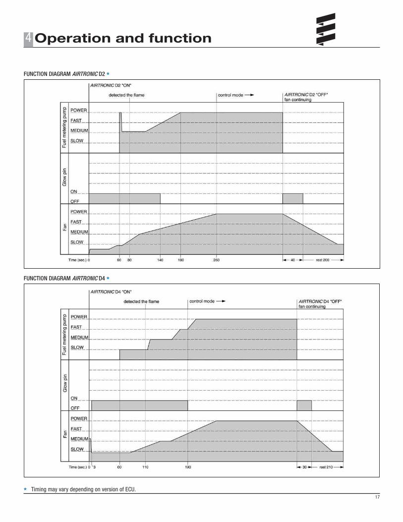
* The timing shown is for the latest Airtronic D2 during normal operation. The timing does not account for ECU timing variances, or special situations. Timing for other Airtronic heaters will vary. When timing is viewed on EDiTH software, timing will be different because of communication delay between computer and the heater or specifics of particular heter models.
a) Blower is momentarily ON during System Check.b) If desired heat level is exceeded, the heater will switch into Stand By. The heater will automatically restart once heat is required. The restart from Stand By is similar to Pre-heat and Ignition attempt stages in Starting Phase.c) The Blower is off during Stand By if an external temperature sensor is connected.d) Time may vary if Glow Pin requires more or less energy to achieve required temperature.e) If ECU detects that heat exchanger temperature is too high for start up, the start up is delayed to allow the heat exchanger to cool down.
FUNCTION DIAGRAM AIRTRONIC D2 *
FUNCTION DIAGRAM AIRTRONIC D4 *
* Timing may vary depending on version of ECU.17
4
1.5Flamesensor
Overheatsensor
Green Blue Blue BlackBlac
k
Natural/Clear
Gre
enBr
own/
Whi
te
1.1 1.2
2.1
2.7
a)
6.1
16 15 14 13 12 11 10 9 8 7 6 5 4 3 2 1
6.2
2.2
5.1
2 1 2 1 2 1
21
Blue
Pink
Blue
/Bla
ck
Blac
k/G
rey
Gre
y
Brow
n
Brow
nW
hite
Blue
/Yel
low
Gre
y/R
edBr
own/
Whi
te
Brow
n
Gre
en/R
edYe
llow
Red
Blue
/Whi
te
Gre
y
Red
Brow
n
Blue
/Whi
te
Gre
y/R
edBr
own/
Whi
teG
reen
/Red
Yello
w
Grey
Green/Red
Red
BrownBrownBlue/WhiteGrey/RedBrown/White
Yellow
Red
Brown
Brown
Blue/White
Yellow
2 1 2 1 2 1 2 1
S1
B1
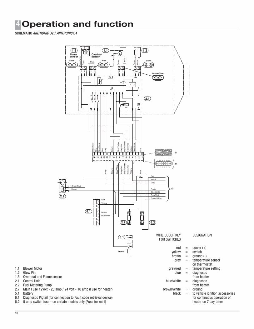
1.1 Blower Motor1.2 Glow Pin1.5 Overheat and Flame sensor2.1 Control Unit2.2 Fuel Metering Pump2.7 Main Fuse 12Volt - 20 amp / 24 volt - 10 amp (Fuse for heater)5.1 Battery6.1 Diagnostic Pigtail (for connection to Fault code retrieval device)6.2 5 amp switch fuse - on certain models only (Fuse for mini)
WIRE COLOR KEY DESIGNATION FOR SWITCHES red = power (+) yellow = switch brown = ground (-) grey = temperature sensor on thermostat grey/red = temperature setting blue = diagnostic from heater blue/white = diagnostic from heater brown/white = ground black = to vehicle ignition accessories for continuous operation of heater on 7 day timer
4
18
SCHEMATIC AIRTRONIC D2 / AIRTRONIC D4
a)
Yellow
Red1 0
3 4 1 2 5 6 T
RED GREENGrey
Grey/Red
Brown/White
a)
Red
6 5
4
3
2 1
S2B2YellowRed
GreyWhite/redBrown
BlueGrey/RedBue/White
Brown/White
Brown
Red
Mini Controller
Yellow
Greyw/ViYellow/Violet
S2 B2
13
52
46
13
52
46
DIAG
TRS
Optional
Yellow
Red
BrownBrown
Brown
yGrey/Red
Blue/WhiteBrown/White
1211
109
87
65
43
21
1 4 7 10
2 5 8 11
3 6 9 12
Yellow
Red
Brown
Grey/Red
Brown/White
Blue/White
B3
a)
1 2
3
4
5
6
9 1
00
YellowRed
yGrey
Brown
yGrey/RedBue/White
Brown/White
rtgn
5
96 4
310
12
12
3
4
0
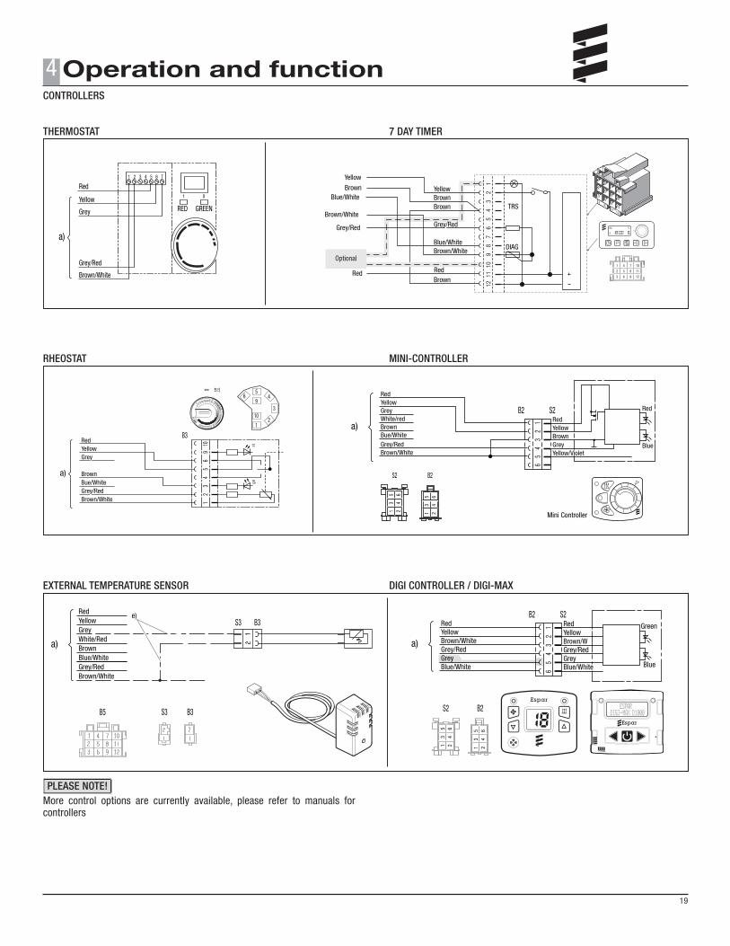
THERMOSTAT
RHEOSTAT
EXTERNAL TEMPERATURE SENSOR
More control options are currently available, please refer to manuals for controllers
7 DAY TIMER
MINI-CONTROLLER
DIGI CONTROLLER / DIGI-MAX
CONTROLLERS
19
4
a)
Green
6 5
4
3
2
1
S2B2
YellowRed
Brown/White
BlueGreyGrey/Red
Blue/White
Brown/W
RedYellow
Grey/RedGreyBlue/White
S2 B2
13
52
46
13
52
46
YellowRed
GreyWhite/RedBrownBlue/WhiteGrey/RedBrown/White
a)
S3 B3
S3B5 B3
e)
PLEASE NOTE!
Optional
Blue/White
12 or 24 Voltsource
Control device
Commonly aGreen Coloured
WireThe Eberspaecher Heater
Diagnostic ConnectorBlock may be used
when available
Commonly a BrownColoured Wire
CutWire
Red BrownOrange Green
Yellow
(Yellow wire onheater’s harness)
Heater EnablePower Source
EberspaecherHeater
Control Unit.
1 2 3 4 5 6 7 8
1 2 3 4 5 6 7 8
4 3 2 1
4 3 2 1
High AltitudeCompensator.
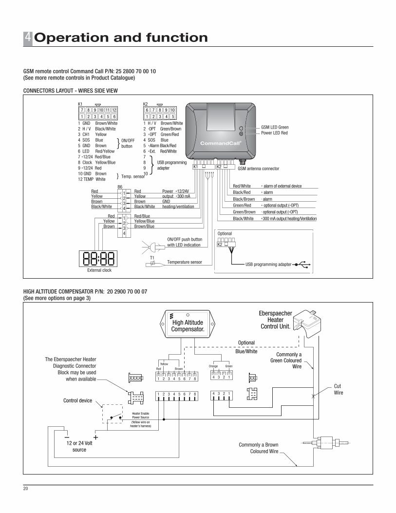
Connectors layout - wires side view
External clock
1 H / V Brown/White2 -OPT Green/Brown3 +OPT Green/Red4 SOS Blue5 +Alarm Black/Red6 +Ext. Red/White78 USB programming9 adapter10
GSM LED GreenPower LED Red
1 GND Brown/White2 H / V Black/White3 CH1 Yellow4 SOS Blue5 GND Brown6 LED Red/Yellow7 +12/24 Red/Blue8 Clock Yellow/Blue9 +12/24 Red10 GND Brown12 TEMP White
ON/OFFbutton
Temp. sensor
K17 8 9 10 11 12
1 2 3 4 5 6
K26 7 8 9 10
1 2 3 4 5
Brown GND
Red Power +12/24VB6
Yellow output +300 mA
Black/White heating/ventilationBrown
RedYellow
Black/White
Brown/Blue
Red/BlueYellow/Blue
Brown
RedYellow
K1
1234
1234
K2 GSM antenna connector
Optional
USB programming adapter
K2
T1Temperature sensor
ON/OFF push buttonwith LED indication
Red/White + alarm of external deviceBlack/Red + alarm
GSM remote control Command Call P/N: 25 2800 70 00 10(See more remote controls in Product Catalogue)
CONNECTORS LAYOUT - WIRES SIDE VIEW
HIGH ALTITUDE COMPENSATOR P/N: 20 2900 70 00 07 (See more options on page 3)
4
20
RECOMMENDED PERIODIC MAINTENANCE
• Remove the glow pin and inspect for carbon build up. Clean if necessary.• Replace the glow pin screen.• Make sure vent hole is not clogged.• Inspect the ducting, the air intake screen and air outlet for restriction or blockage.• Inspect wires and connectors for damage or corrosion, repair if necessary.• Inspect combustion air intake and exhaust for blockage.• Operate your heater for a minimum of 20 minutes each month.• Maintain your batteries and all electrical connections in good condition. With insufficient power the heater will not start. Low and high voltage cutouts will shut the heater down automatically.• Use fuel suitable for the climate (see fuel supplier recomendations). Blending used engine oil with diesel fuel is not permitted.
BASIC TROUBLESHOOTING
Check List:
What happens when the heater is switched on and...
Heater does not ignite
1 Blower motor does not run Check: - Fuse in power harness. - Power to control unit. - Power to and from switch. - Electrical connections.
2 Blower motor runs approximately 20 seconds and then shuts off Check: - Ensure voltage at control unit remains above 12V (or 24V) during start up with glow pin circuit on.
3 Blower motor runs/fuel metering pump starts and then shuts down after two start up attempts Check: - Ventilation hole and glow pin screen. - Fuel lines and fuel filter. - Fuel quantity. Pg. 29 - Combustion air or exhaust tube blockage.4 Blower motor runs/no fuel metering pump Check: - For electrical pulses at fuel metering pump. - If pump is frozen. - Blocked fuel line.
Heater ignites
1 Shuts down at random Check: - Possible overheat. - Control unit input voltage.
2 Heater smokes and carbons up Check: - Exhaust pipe blocked. - Combustion air intake blocked. - Exhaust entering combustion air intake pipe. - Short cycling, rapid on/off operation. - Fuel system. - Fuel metering pump position and quantity. - Motor rpm.
SELF DIAGNOSTICS The heater is equipped with self diagnostic capabilities. The most powerful diagnostic option is the Basic adapter P/N: 22 1541 89 00 00 or Universal Diagnostic Unit P/N: 20 2800 70 12 00 along with EDiTH software. The conventional “diagnostic fault code retriever” (P/N: 20 2900 70 50 60) is an alternative option, it can be carried in your pocket and a Personal computer is not needed.
The diagnostic devises will be able to perform the functions below.
1. Access the current fault which is affecting the heater.2. Access the five previous faults which affected the heater.3. Clear the fault memory to erase previous fault history.4. Unlock control units.5. Start heater.
DIAGNOSTIC FAULT CODE RETRIEVER
Refer to manual for Diagnostic tools available at espar.eberspaecher.com/help.
MAINTENANCE
5
21
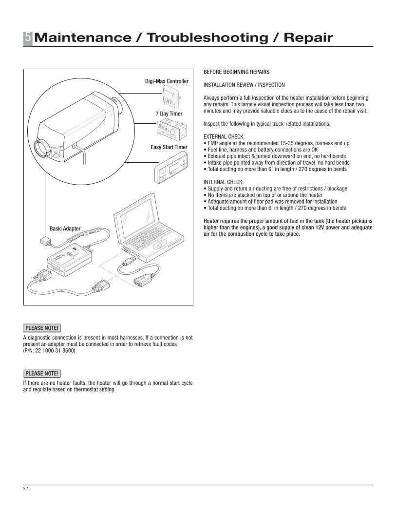
Basic Adapter
Easy Start Timer
7 Day Timer
Digi-Max Controller
A diagnostic connection is present in most harnesses. If a connection is not present an adapter must be connected in order to retrieve fault codes (P/N: 22 1000 31 8600)
If there are no heater faults, the heater will go through a normal start cycle and regulate based on thermostat setting.
BEFORE BEGINNING REPAIRS
INSTALLATION REVIEW / INSPECTION
Always perform a full inspection of the heater installation before beginningany repairs. This largely visual inspection process will take less than twominutes and may provide valuable clues as to the cause of the repair visit.
Inspect the following in typical truck-related installations:
EXTERNAL CHECK:• FMP angle at the recommended 15-35 degrees, harness end up• Fuel line, harness and battery connections are OK• Exhaust pipe intact & turned downward on end, no hard bends• Intake pipe pointed away from direction of travel, no hard bends• Total ducting no more than 6” in length / 270 degrees in bends
INTERNAL CHECK:• Supply and return air ducting are free of restrictions / blockage• No items are stacked on top of or around the heater• Adequate amount of floor pad was removed for installation• Total ducting no more than 6’ in length / 270 degrees in bends
Heater requires the proper amount of fuel in the tank (the heater pickup is higher than the engines), a good supply of clean 12V power and adequate air for the combustion cycle to take place.
5
22
PLEASE NOTE!
PLEASE NOTE!
--- Diagnosis not possible • Check electrical connections. • Diagnostic Devise defective. • Test ECU and replace if necessary.
000 Normal Operation • No faulty condition detected by the ECU. If heater runs in ventilation mode instead of heating, check harness for damage and combo sensor.
004 Short circuit at external blower output Function normally not used in North America • Check for short circuit between pin 16 (B1) and appropriate relay. • If there is no short, test ECU and replace if necessary.
005 Short circuit at security system output Function normally not used in North America • Check for short circuit between pin 15 (B1) and appropriate relay or security system input. • If there is no short, test ECU and replace if necessary.
006° Altitude sensor fault • Check if sensor is connected properly. (Only applicable with “H-kit” heaters°) • Connect sensor to EDITH for further diagnosis.
009 ADR – shutdown Optional safety shutdown Function normally not used in North America • Signal at pin 13 (S1) changed from (+) to (-) or a (+) signal is detected at pin 14 (S1). • If above does not resolve problem test ECU and replace if necessary.
010 Overvoltage Overvoltage detected for at least 20 seconds without interruption. • Check voltage between pin 1 (red wire) and 10 (brown wire) (B1). Voltage here should be the same as the battery. • Voltage must be less then 16 volts for 12 volt heater. • Voltage must be less then 32 volts for 24 volt heater. • Check if battery charger is connected. If so disconnect charger. • Check vehicle charging system. If there is a problem correct as necessary.
011 Undervoltage Undervoltage detected for at least 20 seconds without interruption. • Check if fuses, connections and wiring are in good condition and battery is charged. • Check voltage between pin 1 (red wire) and 10 (brown wire) (B1), while heater starts. • If voltage is low check fuses and wiring for damage. Check battery connections for corrosion and proper contact. • Voltage must be more then 10.5 volts for 12 volt heater. • Voltage must be more then 21 volts for 24 volt heater. • Correct as necessary if there is a problem with vehicle charging system.
012 Overheat at overheat sensor • Check air ducting for excessive restriction or blockage. • Check if ducting length is within specification. (Ref. to product catalogue) • Measure resistance of both the overheat sensor and flame sensor to see if they are within specification. (pg. 29) • Perform Fuel Quantity Test. (pg. 29), replace pump if necessary. • If overheat happens on altitudes above 1,500m (4,920”) - Upgrade the system for altitude compensation.
013 Overheat at flame sensor • Check air ducting for excessive restriction or blockage. • Check if ducting length is within specification. (Ref. to product catalogue) • Measure resistance of both the flame sensor and overheat sensor to see if they are within specification. (pg. 29) • Check the fuel pump angle. • Perform Fuel Quantity Test. (pg. 29), replace pump if necessary.
014 Excessive temperature difference between • Check if sensor is mounted properly. overheat and flame sensor • Measure resistance of flame sensor and overheat sensor to see if it is within specification. (pg. 29) • Perform fuel quantity test. (pg. 29)
FAULT CODE FAULT DESCRIPTION CAUSES / REPAIR
5
23
5
24
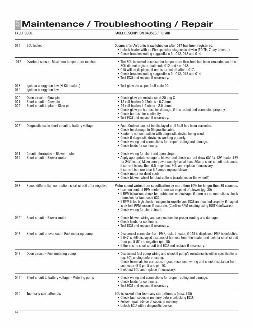
015 ECU locked Occurs after Airtronic is switched on after 017 has been registered. • Unlock heater with an Eberspaecher diagnostic devise (EDITH, 7 day timer…) • Check troubleshooting suggestions for 012, 013 and 014.
017 Overheat sensor -Maximum temperature reached • The ECU is locked because the temperature threshold has been exceeded and the ECU did not register fault code 012 and / or 013. • 015 will be displayed if unit is turned off after a 017. • Check troubleshooting suggestions for 012, 013 and 014. • Test ECU and replace if necessary.
018 Ignition energy too low (H-Kit heaters) • Test glow pin as per fault code 20.019 Ignition energy too low
020 Open circuit – Glow pin • Check glow pin resistance at 20 deg C021 Short circuit – Glow pin • 12 volt heater: 0.42ohms - 0.7ohms022* Short circuit to plus – Glow pin • 24 volt heater: 1.2 ohms - 2.0 ohms • Check glow pin harness for damage, if it is routed and connected properly. • Check harness for continuity. • Test ECU and replace if necessary.
025* Diagnostic cable short circuit to battery voltage • Fault Code(s) can not be displayed until fault has been corrected. • Check for damage to Diagnostic cable. • Heater is not compatible with diagnostic devise being used. • Check if diagnostic device is working properly. • Check wiring and connections for proper routing and damage. • Check leads for continuity.
031 Circuit interrupted – Blower motor • Check wiring for short and open cirquit.032 Short circuit – Blower motor • Apply appropriate voltage to blower and check current draw (8V for 12V heater 18V for 24V heater) Make sure power supply has at least 20amp short circuit resistance. If current is less then 6.5 amps test ECU and replace if necessary. If current is more then 6.5 amps replace blower. • Check motor for dead spots. • Check blower wheel for obstructions (scratches on the wheel?)
033 Speed differential, no rotation, short circuit after negative Motor speed varies from specification by more then 10% for longer then 30 seconds. • Use non contact RPM meter to measure speed of blower (pg. 30) • If RPM is too low, check for restrictions or blockage, if there are no restrictions check remedies for fault code 032. • If RPM is too high check if magnet in impeller and ECU are mounted properly, if magnet is ok test RPM sensor if accurate. (Confirm RPM reading using EDITH software.) • Check wiring for short circuit. 034* Short circuit – Blower motor • Check blower wiring and connections for proper routing and damage. • Check leads for continuity. • Test ECU and replace if necessary.
047 Short circuit or overload – Fuel metering pump • Disconnect connector from FMP, restart heater, if 048 is displayed, FMP is defective. • If 047 is still displayed disconnect harness from the heater and look for short circuit from pin 5 (B1) to negative (pin 10) • If there is no short circuit test ECU and replace if necessary.
048 Open circuit – Fuel metering pump • Disconnect fuel pump wiring and check if pump’s resistance is within specifications (pg. 30), unplug before testing. Check terminals for corrosion, if good reconnect wiring and check resistance from connector (B1) pin 5 and pin 10. • If ok test ECU and replace if necessary.
049* Short circuit to battery voltage - Metering pump • Check wiring and connections for proper routing and damage. • Check leads for continuity. • Test ECU and replace if necessary
050 Too many start attempts ECU is locked after too many start attempts (max. 255) • Check fault codes in memory before unlocking ECU. • Follow repair advice of codes in memory. • Unlock ECU with a diagnostic device.
FAULT CODE FAULT DESCRIPTION CAUSES / REPAIR
5
25
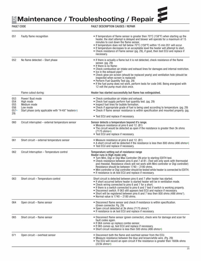
051 Faulty flame recognition • If temperature of flame sensor is greater then 70°C (158°F) when starting up the heater, the start attempt is delayed and blower will operate for a maximum of 15 minutes to cool down the flame sensor. • If temperature does not fall below 70°C (158°F) within 15 min 051 will occur. • If temperature decreases to an acceptable level the heater will attempt to start. • Check resistance of Flame sensor (pg. 29), if good, then test ECU and replace if necessary.
052 No flame detected – Start phase • If there is actually a flame but it is not detected, check resistance of the flame sensor. (pg. 29) • If there is no flame: • Check combustion air intake and exhaust lines for damages and internal restriction. • Ice in the exhaust pipe? • Check glow pin screen (should be replaced yearly) and ventilation hole (should be inspected when screen is replaced) • Perform Fuel Quantity Test (pg. 29) • If the fuel pump does not work, perform tests for code 048. Being energized with 12 volt the pump must click once.
Flame cutout during: Heater has started successfully but flame has extinguished.
053 Power/ Bust mode • Check combustion air intake and exhaust.054 High mode • Check fuel supply perform fuel quantity test. (pg. 29)055 Medium mode • Inspect fuel lines for bubble formation.056 Low mode • Check if appropriate grade of fuel is being used according to temperature. (pg. 29)057° Start phase (only applicable with “H-Kit” heaters°) • Check if flame sensor resistance is within specification and mounted properly. (pg. 29) • Test ECU and replace if necessary.
060 Circuit interrupted – external temperature sensor Sensor detects a temperature beyond it’s range. • Measure resistance at pins 6 and 12. (B1) • The circuit would be detected as open if the resistance is greater then 3k ohms (7175 ohms•) • Test ECU and replace if necessary.
061 Short circuit – external temperature sensor • Measure resistance at pins 6 and 12. (B1) • A short circuit will be detected if the resistance is less then 800 ohms (486 ohms•) • Test ECU and replace if necessary.
062 Circuit Interruption – Temperature control Temperature setting out of resistance range Heater runs in High mode only • Turn Mini, Digi or Digi Max Controller ON prior to starting EDITH test. • Check resistance between pins 6 and 7 at B1. (Test will only work with thermostat and rheostat. Resistance check will not work with Mini controller or Digi controller) Resistance should be between 1740 – 2180 ohms. • Mini controller or Digi controller should be tested while heater is connected to EDITH. • If resistance is ok test ECU and replace if necessary.
063 Short circuit – Temperature control Short circuit is detected between pins 6 and 7 after heater has started. • If short occurred before heater is started heater will be in ventilation mode. • Check wiring connected to pins 6 and 7 for a short. • If there is a switch connected to pins 6 and 7 test if switch is working properly. • Disconnect switch. If 063 still appears test ECU and replace if necessary. • Short will be registered between pins 6 and 7 less then 800 ohms (486 ohms*). • Normal value is 1740 – 2180 ohms.
064 Open circuit – flame sensor • Disconnect flame sensor and check if resistance is within specification. (Green connector. Pg. 29) • Open circuit detected at 3k ohms (7175 ohms*) • If resistance is ok test ECU and replace if necessary.
065 Short circuit – flame sensor • Disconnect flame sensor (green connector), check wire for damage and scan for fault codes again. • If 064 comes up replace combo sensor. • If 065 comes up, test ECU and replace if necessary. • Short circuit resistance is less then 500 ohms (486 ohms•)
071 Open circuit – overheat sensor • Disconnect both the flame and overheat sensor from the ECU. • Measure resistance between the blue and brown/white wire. (Pg. 29) • The ECU will record an open circuit if the resistance is greater then 1600k ohms (223k ohms•)
FAULT CODE FAULT DESCRIPTION CAUSES / REPAIR
5
26
072 Short circuit- overheat sensor • Disconnect both the flame and overheat sensor from the ECU, check wire for damage and scan for fault codes again. • If 071 comes up replace combo sensor. • If fault 072 is still displayed test ECU and replace if necessary. • Short circuit resistance is less then 95 ohms (183 ohms•)
074* Overheat threshold not detected • Inspect combo sensor for damage. • Test ECU and replace if necessary.
090 Control Unit defective • Disconnect power for 10 seconds. Reconnect and test again. • Test ECU and replace if necessary.
091 External voltage interference Fault due to inconsistent voltage • Inspect power system. (Battery, Battery charger, Alternator) • Check the fuses, the supply cables, the negative connections and the positive support point on the battery for corrosion and correct contact.
092 Internal Memory Error or Control Unit defective • Disconnect power for 10 seconds. Reconnect and test again.093* • Test ECU and replace if necessary.094095*
096 Internal temperature sensor defective • Replace ECU or install an external temperature sensor.
097 Control Unit defective • Replace Control Unit.
098* Voltage less then 5 - 6 volt (for 12 volt) or less then 7 - 8 volt (for 24 volt heater)
099* Too many resets in sequence • Check the fuses, the supply cables, the negative connections and the positive support point on the battery for corrosion and correct contact. • Check if power supply can provide the appropriate amount of current while heater is running. (At least 10 amp supply recommended.)
Transistor error in control box. • Check lead harness of the external components for continuity, has been correctly laid and check for damage. • Test ECU and replace if necessary.
HIGH ALTITUDE SENSOR FAULT CODE FAULT DESCRIPTION CAUSES / REPAIR
0 No faults.
11 Communication Lost. • Check wiring and connections
12 No altitude adjustment. • Use heater that is compatible with this high altitude sensor or use a different high altitude device (Pg. 3)
13 Air pressure sensor fault. • Replace the air pressure sensor.
* Codes are only applicable for new style ECU’s. To date new style ECU’s wiring is wrapped with tape. Old style ECU’s are bundled in PVC.
° Codes and comments apply to ECU’s with integrated high altitude compatibilities. (Ref. pg. 3)
• Resistance values apply to old style ECU’s. Ref. to * for description of difference between old and new style ECU’s.
FAULT CODE FAULT DESCRIPTION CAUSES / REPAIR
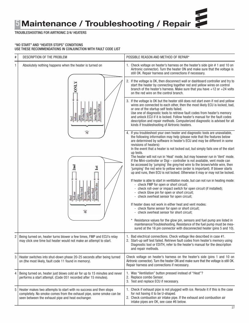
“NO START” AND “HEATER STOPS” CONDITIONSUSE THESE RECOMMENDATIONS IN CONJUNCTION WITH FAULT CODE LIST
# DESCRIPTION OF THE PROBLEM
1 Absolutely nothing happens when the heater is turned on
2 Being turned on, heater turns blower a few times, FMP and ECU’s relay may click one time but heater would not make an attempt to start.
3 Heater switches into shut-down phase 20-25 seconds after being turned on (the most likely, fault code 11 found in memory).
4 Being turned on, heater just blows cold air for up to 15 minutes and never performs a start attempt. (Code 051 recorded after 15 minutes).
5 Heater makes two attempts to start with no success and then stops completely. No smoke comes from the exhaust pipe, some smoke can be seen between the exhaust pipe and heat exchanger.
POSSIBLE REASON AND METHOD OF REPAIR*
1. Check voltage on heater’s harness on the heater’s side (pin # 1 and 10 on Airtronic connector). Turn the heater ON and make sure that the voltage is still OK. Repair harness and connections if necessary.
2. If the voltage is OK, then disconnect wall or dashboard controller and try to start the heater by connecting together red and yellow wires on control branch of the heater’s harness. Make sure that you have +12 or +24 volts on the red wire on the control branch.
3. If the voltage is OK but the heater still does not start even if red and yellow wires are connected to each other, then the most likely ECU is locked, bad, or one of the startup self tests failed. Use one of diagnostic tools to retrieve fault codes from heater’s memory and unlock ECU if it is locked. Follow heater’s manual for the fault codes description and repair methods. Computerized diagnostic is advised for all kinds if troubleshooting of Airtronic heaters.
4. If you troubleshoot your own heater and diagnostic tools are unavailable, the following information may help (please note that the features below are determined by software in heater’s ECU and may be different in some revisions of heaters): In the event that a heater is not locked out, but simply fails one of the start up tests. The heater will not run in ‘Heat’ mode, but may however run in ‘Vent’ mode. If the Mini-controller or Digi – controller is not available, vent mode can be accessed by ‘jumping’ the grey/red wire to the brown/white wire, then ‘jumping’ the red wire to yellow wire (order is important). If blower starts up and runs, then ECU is not locked. Otherwise it may or may not be locked.
If heater is able to start in ventilation mode, but can not run in heating mode: - check FMP for open or short circuit; - check roll-over or impact switch for open circuit (if installed); - check Glow pin for open or short circuit; - check overheat sensor for open circuit; If heater does not work in either heat and vent modes: - check flame sensor for open or short circuit; - check overheat sensor for short circuit;
* Resistance values for the glow pin, sensors and fuel pump are listed in maintenance/Troubleshooting. Resistance of the fuel pump must be mea- sured at the 16 pin connector with disconnected heater (pins 5 and 10). 1. Bad electrical connections. Check voltage like described in case #1.2. Start-up self test failed. Retrieve fault codes from heater’s memory using Diagnostic tool or EDiTH, refer to the heater’s manual for the description and repair methods. Check voltage on heater’s harness on the heater’s side (pins 1 and 10 on Airtronic connector). Turn the heater ON and make sure that the voltage is still OK. Repair harness and connections if necessary.
1. Was “Ventilation” button pressed instead of “Heat”?2. Replace combo Sensor.3. Test and replace ECU if necessary.
1. Check if exhaust pipe is not plugged with ice. Reroute it if this is the case for not having it to be U-shaped.2. Check combustion air intake pipe. If the exhaust and combustion air intake pipes are OK, see case #6 below.
TROUBLESHOOTING FOR AIRTRONIC 2/4/ HEATERS
5
27
TROUBLESHOOTING FOR AIRTRONIC 2/4/ HEATERS
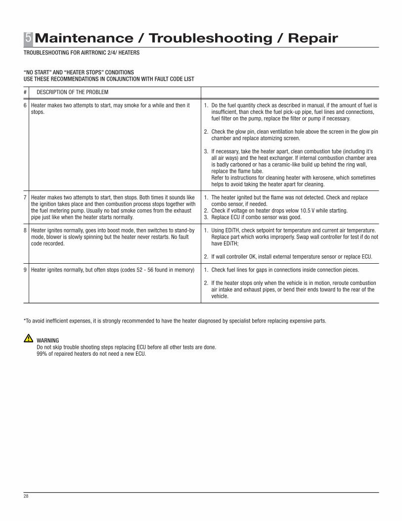
*To avoid inefficient expenses, it is strongly recommended to have the heater diagnosed by specialist before replacing expensive parts.
WARNING Do not skip trouble shooting steps replacing ECU before all other tests are done. 99% of repaired heaters do not need a new ECU.
5
28
“NO START” AND “HEATER STOPS” CONDITIONSUSE THESE RECOMMENDATIONS IN CONJUNCTION WITH FAULT CODE LIST
# DESCRIPTION OF THE PROBLEM
6 Heater makes two attempts to start, may smoke for a while and then it stops.
7 Heater makes two attempts to start, then stops. Both times it sounds like the ignition takes place and then combustion process stops together with the fuel metering pump. Usually no bad smoke comes from the exhaust pipe just like when the heater starts normally.
8 Heater ignites normally, goes into boost mode, then switches to stand-by mode, blower is slowly spinning but the heater never restarts. No fault code recorded.
9 Heater ignites normally, but often stops (codes 52 - 56 found in memory)
1. Do the fuel quantity check as described in manual, if the amount of fuel is insufficient, than check the fuel pick-up pipe, fuel lines and connections, fuel filter on the pump, replace the filter or pump if necessary.
2. Check the glow pin, clean ventilation hole above the screen in the glow pin chamber and replace atomizing screen.
3. If necessary, take the heater apart, clean combustion tube (including it’s all air ways) and the heat exchanger. If internal combustion chamber area is badly carboned or has a ceramic-like build up behind the ring wall, replace the flame tube. Refer to instructions for cleaning heater with kerosene, which sometimes helps to avoid taking the heater apart for cleaning.
1. The heater ignited but the flame was not detected. Check and replace combo sensor, if needed.2. Check if voltage on heater drops velow 10.5 V while starting.3. Replace ECU if combo sensor was good.
1. Using EDiTH, check setpoint for temperature and current air temperature. Replace part which works improperly. Swap wall controller for test if do not have EDiTH;
2. If wall controller OK, install external temperature sensor or replace ECU.
1. Check fuel lines for gaps in connections inside connection pieces.
2. If the heater stops only when the vehicle is in motion, reroute combustion air intake and exhaust pipes, or bend their ends toward to the rear of the vehicle.
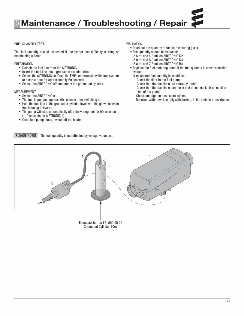
FUEL QUANTITY TEST
The fuel quantity should be tested if the heater has difficulty starting or maintaining a flame.
PREPARATION • Detach the fuel line from the AIRTRONIC. • Insert the fuel line into a graduated cylinder 10ml. • Switch the AIRTRONIC on. Once the FMP comes on allow the fuel system to bleed air out for approximately 60 seconds. • Switch the AIRTRONIC off and empty the graduated cylinder.
MEASUREMENT • Switch the AIRTRONIC on. • The fuel is pumped approx. 60 seconds after switching on. • Hold the fuel line in the graduated cylinder level with the glow pin while fuel is being delivered. • The pump will stop automatically after delivering fuel for 90 seconds (110 seconds for AIRTRONIC 4). • Once fuel pump stops, switch off the heater.
The fuel quantity is not affected by voltage variances.
EVALUATION • Read out the quantity of fuel in measuring glass. • Fuel quantity should be between: 3.5 ml and 4.3 ml. on AIRTRONIC D2 5.0 ml and 6.0 ml. on AIRTRONIC D4 6.8 ml and 7.6 ml. on AIRTRONIC B4 • Replace the fuel metering pump if the fuel quantity is above specified value. If measured fuel quantity is insufficient: – Check the filter in the fuel pump. – Check that the fuel lines are correctly routed. – Check that the fuel lines don’t leak and do not suck air on suction side of the pump. – Check and tighten hose connections. – Does fuel withdrawal comply with the data in the technical description.
5
29
PLEASE NOTE!
1
2
3
4
Eberspaecher part #: 552 00 04Graduated Cylinder 10ml
2000
1800
1600
1200
1000
800
600
400
200
0-40 -20 0 20 40 60 80 100 140120 200
Temperature (°C)
Resi
stan
ce (k
Ohm
)
2400
2200
2000
1800
1600
1400
1200
1000
800-40 0 50 100 150
Temperature (°C)
Resi
stan
ce (k
Ohm
)
200 250 300 350
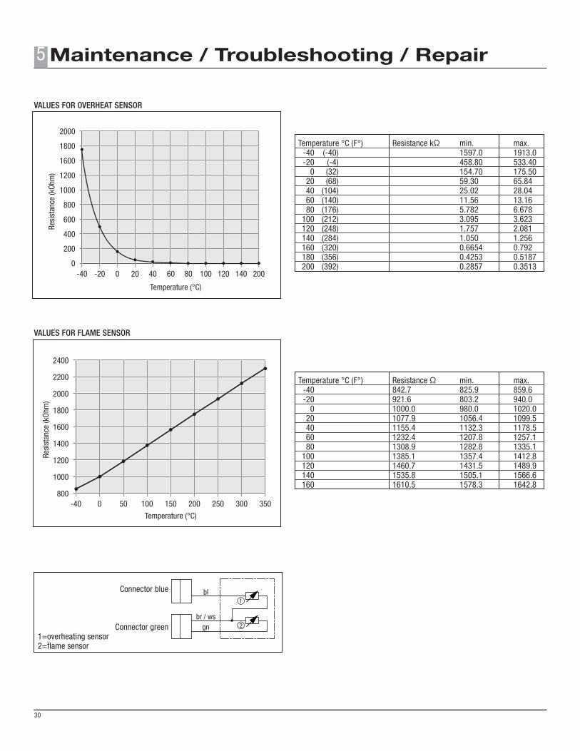
VALUES FOR OVERHEAT SENSOR
VALUES FOR FLAME SENSOR
Connector blue
Connector green 1=overheating sensor 2=flame sensor
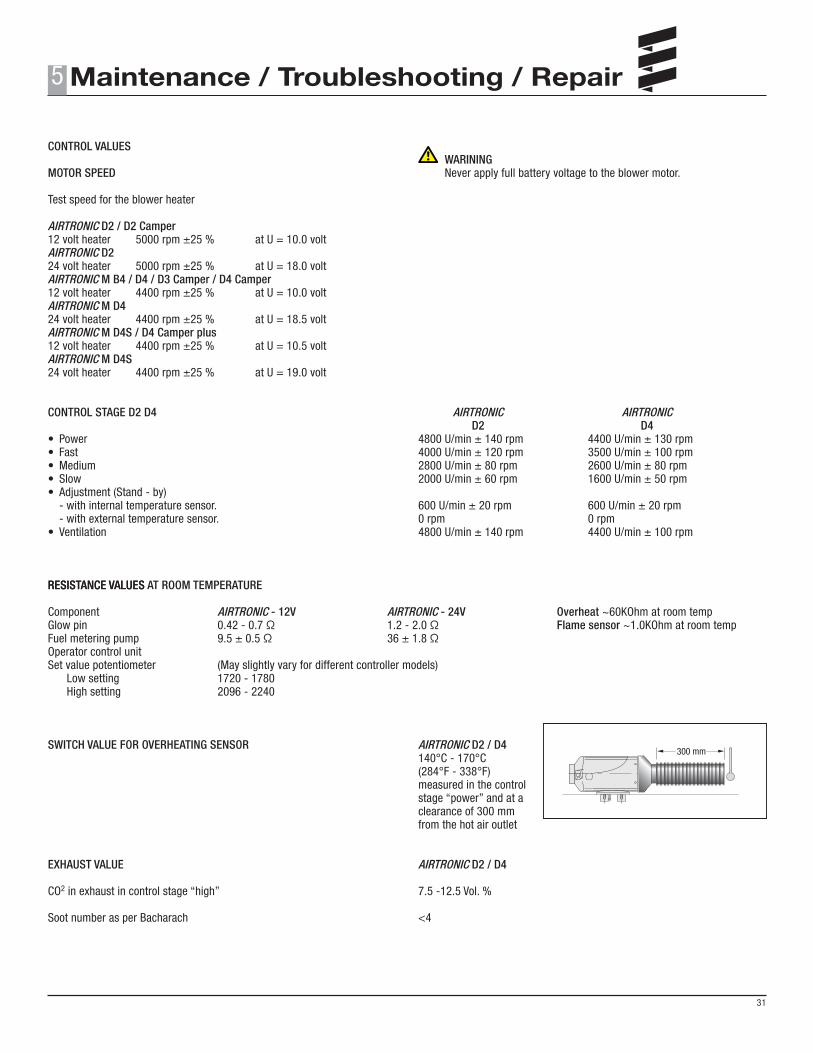
AIRTRONIC D2 / D2 Camper12 volt heater 5000 rpm ±25 % at U = 10.0 voltAIRTRONIC D224 volt heater 5000 rpm ±25 % at U = 18.0 voltAIRTRONIC M B4 / D4 / D3 Camper / D4 Camper12 volt heater 4400 rpm ±25 % at U = 10.0 voltAIRTRONIC M D424 volt heater 4400 rpm ±25 % at U = 18.5 voltAIRTRONIC M D4S / D4 Camper plus12 volt heater 4400 rpm ±25 % at U = 10.5 voltAIRTRONIC M D4S24 volt heater 4400 rpm ±25 % at U = 19.0 volt
CONTROL STAGE D2 D4
• Power • Fast• Medium• Slow• Adjustment (Stand - by) - with internal temperature sensor. - with external temperature sensor. • Ventilation
RESISTANCE VALUES
SWITCH VALUE FOR OVERHEATING SENSOR
EXHAUST VALUE
CO2 in exhaust in control stage “high” Soot number as per Bacharach
WARINING Never apply full battery voltage to the blower motor.
AIRTRONIC D2 / D4140°C - 170°C(284°F - 338°F)measured in the controlstage “power” and at aclearance of 300 mmfrom the hot air outlet
AIRTRONIC D2 / D4
7.5 -12.5 Vol. %
<4
5
31
RESISTANCE VALUES AT ROOM TEMPERATURE
Component AIRTRONIC - 12V AIRTRONIC - 24V Overheat ~60KOhm at room tempGlow pin 0.42 - 0.7 Ω 1.2 - 2.0 Ω Flame sensor ~1.0KOhm at room tempFuel metering pump 9.5 ± 0.5 Ω 36 ± 1.8 ΩOperator control unitSet value potentiometer (May slightly vary for different controller models) Low setting 1720 - 1780 High setting 2096 - 2240
300 mm
1
b
a 2
b a c
d
REPAIR INSTRUCTIONS
Removing the coverRemoving and checking the control unitRemoving the glow pinRemoving the liningRemoving and checking the overheat and flame sensorInstalling the overheat and flame sensorDismantling the heat exchangerRemoving the combustion air blowerRemoving the combustion chamber
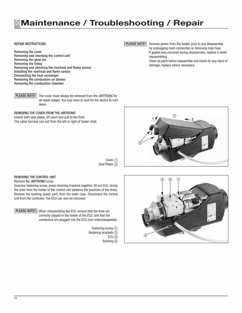
The cover must always be removed from the AIRTRONIC for all repair stages. You may have to wait for the device to cool down.
REMOVING THE COVER FROM THE AIRTRONICUnlock both seal plates, lift cover and pull to the front.The cable harness can exit from the left or right of heater shell.
Cover a Seal Plates b
REMOVING THE CONTROL UNITRemove the AIRTRONIC cover.Unscrew fastening screw, press retaining brackets together, lift out ECU. Unclip the lines from the holder of the control unit (observe the positions of the lines). Remove the bushing (lower part) from the outer case. Disconnect the control unit from the controller. The ECU can now be removed.
When reassembling the ECU, ensure that the lines are correctly clipped in the holder of the ECU, and that the connectors are plugged into the ECU (non-interchangeable).
Fastening screw a Retaining brackets b
ECU c Bushing d
Remove power from the heater prior to any disassembly by unplugging main connection or removing main fuse. If gasket was removed during disassembly, replace it when reassembling. Clean all parts before reassembly and check for any signs of damage, replace where necessary.
5
32
PLEASE NOTE!
PLEASE NOTE!
PLEASE NOTE!
90°
b
a
c
a
c
b
b
a
b
a
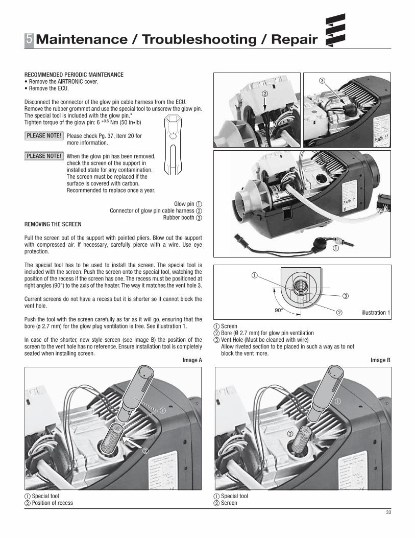
RECOMMENDED PERIODIC MAINTENANCE• Remove the AIRTRONIC cover.• Remove the ECU.
Disconnect the connector of the glow pin cable harness from the ECU.Remove the rubber grommet and use the special tool to unscrew the glow pin.The special tool is included with the glow pin.*Tighten torque of the glow pin: 6 +0.5 Nm (50 in•lb)
Please check Pg. 37, item 20 for more information.
When the glow pin has been removed, check the screen of the support in installed state for any contamination. The screen must be replaced if the surface is covered with carbon. Recommended to replace once a year.
Glow pin aConnector of glow pin cable harness b
Rubber booth cREMOVING THE SCREEN
Pull the screen out of the support with pointed pliers. Blow out the support with compressed air. If necessary, carefully pierce with a wire. Use eye protection.
The special tool has to be used to install the screen. The special tool is included with the screen. Push the screen onto the special tool, watching the position of the recess if the screen has one. The recess must be positioned at right angles (90°) to the axis of the heater. The way it matches the vent hole 3.
Current screens do not have a recess but it is shorter so it cannot block the vent hole.
Push the tool with the screen carefully as far as it will go, ensuring that the bore (ø 2.7 mm) for the glow plug ventilation is free. See illustration 1.
In case of the shorter, new style screen (see image B) the position of the screen to the vent hole has no reference. Ensure installation tool is completely seated when installing screen.
Image A
aSpecial toolbPosition of recess
illustration 1
aScreenbBore (Ø 2.7 mm) for glow pin ventilation cVent Hole (Must be cleaned with wire) Allow riveted section to be placed in such a way as to not block the vent more.
Image B
aSpecial toolbScreen
5
33
PLEASE NOTE!
PLEASE NOTE!
a
b
a
b
�
�
bl
br / wsgn
b
a
b
c
a
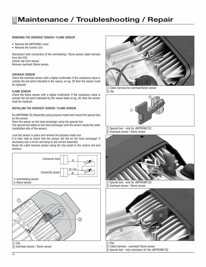
REMOVING THE OVERHEAT SENSOR / FLAME SENSOR • Remove the AIRTRONIC cover.• Remove the control unit.
Disconnect both connectors of the overheating / flame sensor cable harness from the ECU.Unlock clip from sensor.Remove overheat /flame sensor.
OVERHEAT SENSORCheck the overheat sensor with a digital multimeter. If the resistance value is outside the set point indicated in the values, on pg. 26 then the sensor must be replaced.
FLAME SENSORCheck the flame sensor with a digital multimeter. If the resistance value is outside the set point indicated by the values table on pg. 26, then the sensor must be replaced.
INSTALLING THE OVERHEAT SENSOR / FLAME SENSOR
For AIRTRONIC D2 (Assembly using purpose made tool) mount the special tool on the sensor.Place the sensor on the heat exchanger using the special tool.The special tool slides on the heat exchanger until the sensor meets the collar (installation site of the sensor).
Lock the sensor in place and remove the purpose made tool.It is then vital to check that the sensor sits flat on the heat exchanger. If necessary use a mirror and lamp to aid correct assembly.Route the cable harness sensor along the clip eyelet to the control unit and connect.
Connector blue
Connector green 1=overheating sensor 2=flame sensor
a Clipb Overheat sensor / flame sensor
aCable harness for overheat/flame sensorbclip
a Special tool - only for AIRTRONIC D2b Overheat sensor / flame sensor
a Special tool - only for AIRTRONIC D2b Overheat sensor / flame sensor
a Clipb Cable harness - overheat/ flame sensorc Special tool - only necessary for the AIRTRONIC D2
5
34
5
2
4
3
1
a
b
c
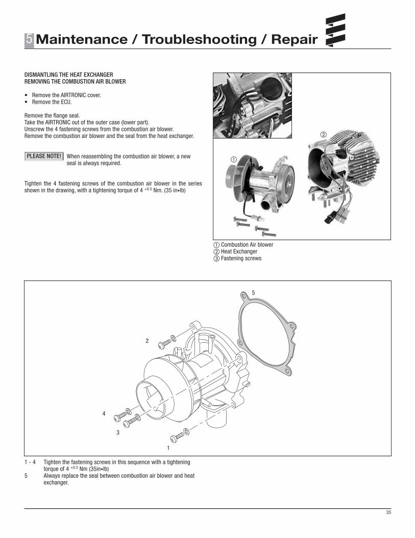
DISMANTLING THE HEAT EXCHANGERREMOVING THE COMBUSTION AIR BLOWER
• Remove the AIRTRONIC cover.• Remove the ECU.
Remove the flange seal.Take the AIRTRONIC out of the outer case (lower part).Unscrew the 4 fastening screws from the combustion air blower.Remove the combustion air blower and the seal from the heat exchanger.
When reassembling the combustion air blower, a new seal is always required.
Tighten the 4 fastening screws of the combustion air blower in the series shown in the drawing, with a tightening torque of 4 +0.5 Nm. (35 in•lb)
1 - 4 Tighten the fastening screws in this sequence with a tightening torque of 4 +0.5 Nm (35in•lb)5 Always replace the seal between combustion air blower and heat exchanger.
a Combustion Air blowerb Heat Exchangerc Fastening screws
5
35
PLEASE NOTE!
4
1
2
3
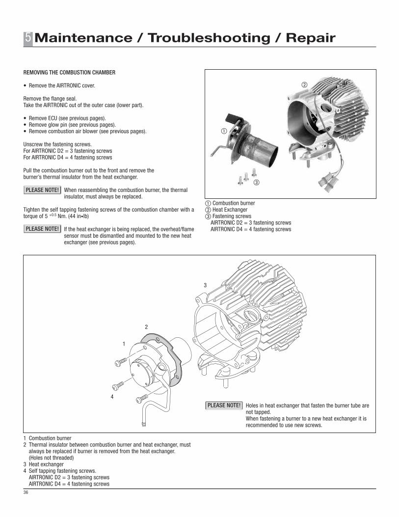
REMOVING THE COMBUSTION CHAMBER • Remove the AIRTRONIC cover.
Remove the flange seal.Take the AIRTRONIC out of the outer case (lower part).
• Remove ECU (see previous pages).• Remove glow pin (see previous pages).• Remove combustion air blower (see previous pages).
Pull the combustion burner out to the front and remove theburner’s thermal insulator from the heat exchanger.
When reassembling the combustion burner, the thermal insulator, must always be replaced.
Tighten the self tapping fastening screws of the combustion chamber with a torque of 5 +0.5 Nm. (44 in•lb)
If the heat exchanger is being replaced, the overheat/flame sensor must be dismantled and mounted to the new heat exchanger (see previous pages).
1 Combustion burner2 Thermal insulator between combustion burner and heat exchanger, must always be replaced if burner is removed from the heat exchanger. (Holes not threaded)3 Heat exchanger4 Self tapping fastening screws. AIRTRONIC D2 = 3 fastening screws AIRTRONIC D4 = 4 fastening screws
Holes in heat exchanger that fasten the burner tube are not tapped. When fastening a burner to a new heat exchanger it is recommended to use new screws.