Page 1
Title page
Alcatel-Lucent 9926
Base Band Unit Node B for W-CDMA
Technical Description
3MN-01792-0001-DEZZA
Issue 0.02 | March 2013
Alcatel-Lucent – Proprietary
Use pursuant to applicable agreements
Use pursuant to applicable agreements
PR
ELIM
IN
AR
YP
RELIM
IN
AR
Y
Page 2
Legal notice
Legal notice
Alcatel, Lucent, Alcatel-Lucent and the Alcatel-Lucent logo are trademarks of Alcatel-Lucent. All other trademarks are the property of their respective
owners.
The information presented is subject to change without notice. Alcatel-Lucent assumes no responsibility for inaccuracies contained herein.
Copyright © 2013 Alcatel-Lucent. All rights reserved.
Contains proprietary/trade secret information which is the property of Alcatel-Lucent and must not be made available to, or copied or used by anyone outside
Alcatel-Lucent without its written authorization.
Not to be used or disclosed except in accordance with applicable agreements.
Use pursuant to applicable agreements
Alcatel-Lucent – Proprietary
Use pursuant to applicable agreements
PR
ELIM
IN
AR
YP
RELIM
IN
AR
Y
Page 3
Contents
About this document
Purpose ............................................................................................................................................................................................. xixi
Reason for reissue ........................................................................................................................................................................ xixi
Intended audience ......................................................................................................................................................................... xixi
Supported systems ........................................................................................................................................................................ xixi
How to use this document ......................................................................................................................................................... xixi
Prerequisites ................................................................................................................................................................................... xixi
Conventions used .......................................................................................................................................................................... xixi
Related information .................................................................................................................................................................... xiixii
Document support ...................................................................................................................................................................... xiiixiii
Technical support ....................................................................................................................................................................... xiiixiii
How to order ................................................................................................................................................................................ xiiixiii
How to comment ........................................................................................................................................................................ xiiixiii
1 UTRAN introduction
Overview ...................................................................................................................................................................................... 1-11-1
UTRAN introduction ............................................................................................................................................................... 1-21-2
2 9926 BBU basic characteristics
Overview ...................................................................................................................................................................................... 2-12-1
9926 BBU introduction .......................................................................................................................................................... 2-22-2
9926 BBU features and functions ....................................................................................................................................... 2-42-4
9926 BBU external interfaces .............................................................................................................................................. 2-72-7
9926 BBU optional features ............................................................................................................................................... 2-112-11
9926 BBU physical and environmental characteristics ............................................................................................ 2-132-13
....................................................................................................................................................................................................................................
Alcatel-Lucent 9926 BBU
3MN-01792-0001-DEZZA
Issue 0.02 March 2013
Alcatel-Lucent – Proprietary
Use pursuant to applicable agreements
iii
PR
ELIM
IN
AR
YP
RELIM
IN
AR
Y
Page 4
3 9926 BBU hardware description
Overview ...................................................................................................................................................................................... 3-13-1
9926 BBU digital shelf
Overview ...................................................................................................................................................................................... 3-33-3
9926 BBU digital shelf modules ......................................................................................................................................... 3-43-4
enhanced Channel Element Module-U (eCEM-U) ...................................................................................................... 3-83-8
enhanced Core Controller Module-U (eCCM-U) ....................................................................................................... 3-113-11
9926 BBU fans tray (48V)
Overview ................................................................................................................................................................................... 3-173-17
9926 BBU fan tray (48V) .................................................................................................................................................... 3-183-18
Rack User Commissioning (RUC) module ................................................................................................................... 3-203-20
9926 BBU optional equipment
Overview ................................................................................................................................................................................... 3-223-22
External Alarm module ........................................................................................................................................................ 3-233-23
enhanced Alarm Module (eAM) ....................................................................................................................................... 3-263-26
PCM Lightning Protection (LPPCM) module ............................................................................................................. 3-293-29
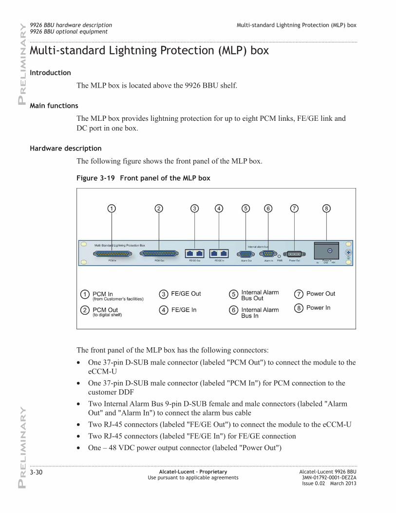
Multi-standard Lightning Protection (MLP) box ....................................................................................................... 3-303-30
9926 BBU with LPPCM and External Alarm modules ............................................................................................ 3-323-32
9926 BBU with LPPCM and enhanced Alarm Module ........................................................................................... 3-333-33
75-ohm kit ................................................................................................................................................................................. 3-343-34
4 Physical characteristics of the 9926 BBU modules
Overview ...................................................................................................................................................................................... 4-14-1
Physical characteristics of the 9926 BBU modules ...................................................................................................... 4-24-2
5 Using the TIL tool
Overview ...................................................................................................................................................................................... 5-15-1
Using the TIL tool ..................................................................................................................................................................... 5-25-2
Contents
....................................................................................................................................................................................................................................
....................................................................................................................................................................................................................................
iv Alcatel-Lucent – Proprietary
Use pursuant to applicable agreements
Alcatel-Lucent 9926 BBU
3MN-01792-0001-DEZZA
Issue 0.02 March 2013
PR
ELIM
IN
AR
YP
RELIM
IN
AR
Y
Page 5
A Reference
Reissue history .......................................................................................................................................................................... A-1A-1
Index
Contents
....................................................................................................................................................................................................................................
....................................................................................................................................................................................................................................
Alcatel-Lucent 9926 BBU
3MN-01792-0001-DEZZA
Issue 0.02 March 2013
Alcatel-Lucent – Proprietary
Use pursuant to applicable agreements
v
PR
ELIM
IN
AR
YP
RELIM
IN
AR
Y
Page 6
Contents
....................................................................................................................................................................................................................................
....................................................................................................................................................................................................................................
vi Alcatel-Lucent – Proprietary
Use pursuant to applicable agreements
Alcatel-Lucent 9926 BBU
3MN-01792-0001-DEZZA
Issue 0.02 March 2013
PR
ELIM
IN
AR
YP
RELIM
IN
AR
Y
Page 7
List of tables
1 Generic terms ............................................................................................................................................................... xiixii
3-1 Backplane and digital modules supported by the 9926 BBU .................................................................... 3-63-6
3-2 eCEM-U corporate LEDs behavior .................................................................................................................. 3-103-10
3-3 Internal Alarm Bus IN/OUT pin connections ............................................................................................... 3-233-23
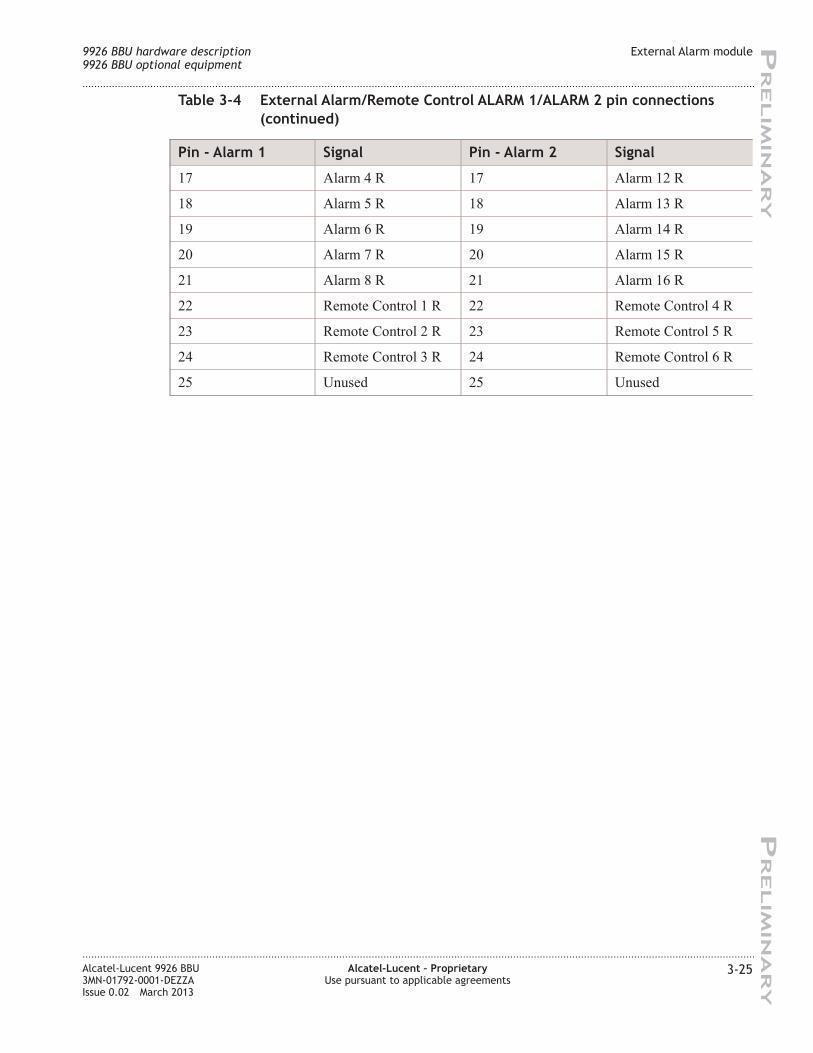
3-4 External Alarm/Remote Control ALARM 1/ALARM 2 pin connections .......................................... 3-243-24
3-5 External user alarm cable pin assignments for connectors 1-16 ............................................................ 3-273-27
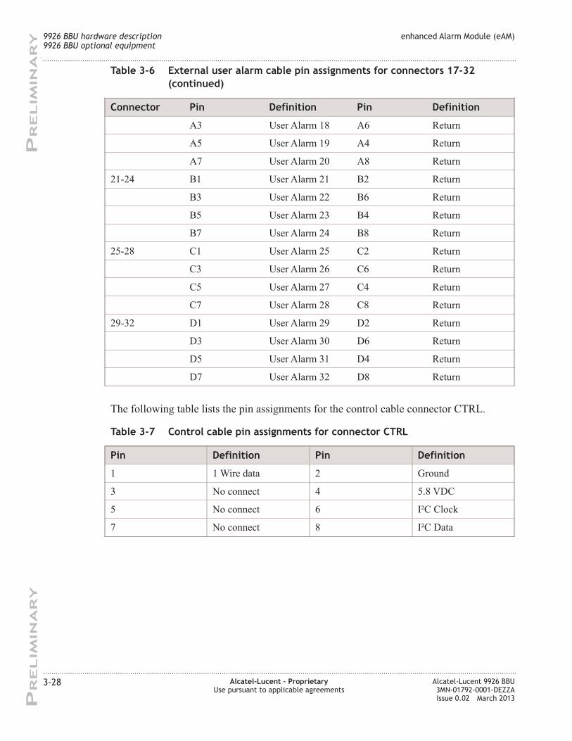
3-6 External user alarm cable pin assignments for connectors 17-32 ......................................................... 3-273-27
3-7 Control cable pin assignments for connector CTRL .................................................................................. 3-283-28
4-1 9926 BBU modules dimensions and weight .................................................................................................... 4-24-2
A-1 Issue 0.02, March 2013, Reason for reissue ................................................................................................... A-1A-1
A-2 Issue 0.01, March 2013, Reason for reissue ................................................................................................... A-1A-1
....................................................................................................................................................................................................................................
Alcatel-Lucent 9926 BBU
3MN-01792-0001-DEZZA
Issue 0.02 March 2013
Alcatel-Lucent – Proprietary
Use pursuant to applicable agreements
vii
PR
ELIM
IN
AR
YP
RELIM
IN
AR
Y
Page 8
List of tables
....................................................................................................................................................................................................................................
....................................................................................................................................................................................................................................
viii Alcatel-Lucent – Proprietary
Use pursuant to applicable agreements
Alcatel-Lucent 9926 BBU
3MN-01792-0001-DEZZA
Issue 0.02 March 2013
PR
ELIM
IN
AR
YP
RELIM
IN
AR
Y
Page 9
List of figures
1-1 Alcatel-Lucent UTRAN architecture example ............................................................................................... 1-41-4
2-1 9926 BBU outside view .......................................................................................................................................... 2-32-3
2-2 9926 BBU with eCCM-U-GE ............................................................................................................................... 2-72-7
2-3 9926 BBU with eCCM-U-E1-4PCM ................................................................................................................. 2-82-8
2-4 Front view of the 9926 BBU with MLP and External Alarm module ................................................. 2-112-11
2-5 Front view of the 9926 BBU with LPPCM and enhanced Alarm Module ........................................ 2-122-12
3-1 9926 BBU outside view .......................................................................................................................................... 0-10-1
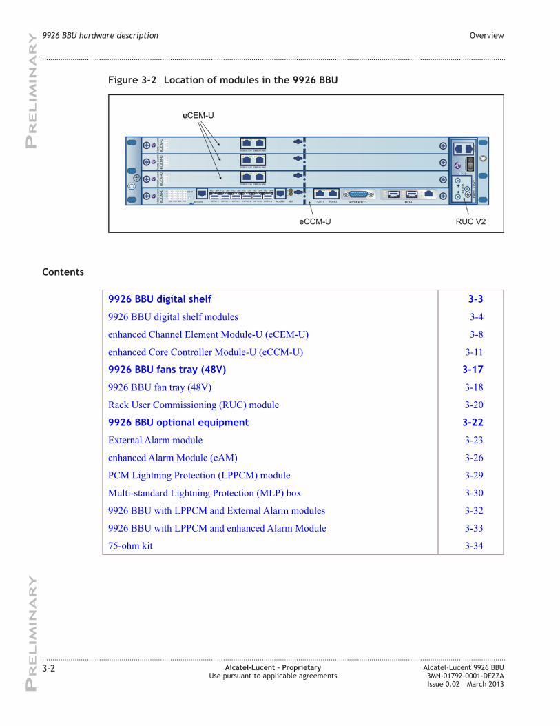
3-2 Location of modules in the 9926 BBU .............................................................................................................. 3-23-2
3-3 9926 BBU RBP .......................................................................................................................................................... 3-43-4
3-4 Pre-cabled 9926 BBU rack with RBP ................................................................................................................ 3-53-5
3-5 9926 BBU functional architecture ....................................................................................................................... 3-63-6
3-6 9926 BBU digital shelf layout .............................................................................................................................. 3-73-7
3-7 eCEM-U front panel ................................................................................................................................................. 3-93-9
3-8 eCEM-U tri-color LEDs .......................................................................................................................................... 3-93-9
3-9 eCCM-U-4E1 configuration front panel ......................................................................................................... 3-123-12
3-10 eCCM-U-GE configuration front panel .......................................................................................................... 3-123-12
3-11 eCCM-U tri-color LEDs ....................................................................................................................................... 3-143-14
3-12 MC-TRX connection on 9926 BBU ................................................................................................................ 3-163-16
3-13 Fan tray view ............................................................................................................................................................ 3-183-18
3-14 9926 BBU air flow paths ...................................................................................................................................... 3-193-19
3-15 9926 BBU RUC module front panel ................................................................................................................ 3-213-21
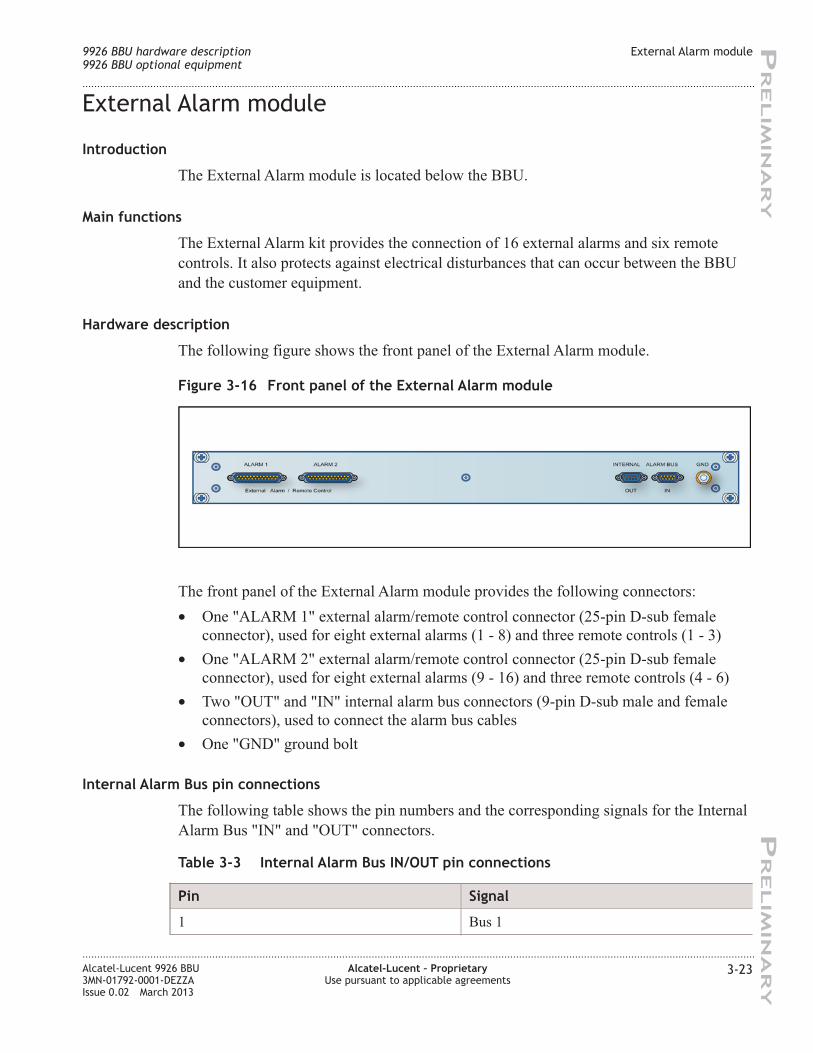
3-16 Front panel of the External Alarm module .................................................................................................... 3-233-23
3-17 Front panel of the eAM module ......................................................................................................................... 3-263-26
....................................................................................................................................................................................................................................
Alcatel-Lucent 9926 BBU
3MN-01792-0001-DEZZA
Issue 0.02 March 2013
Alcatel-Lucent – Proprietary
Use pursuant to applicable agreements
ix
PR
ELIM
IN
AR
YP
RELIM
IN
AR
Y
Page 10
3-18 Front panel of the LPPCM module ................................................................................................................... 3-293-29
3-19 Front panel of the MLP box ................................................................................................................................ 3-303-30
3-20 Front view of the 99326 BBU with LPPCM and External Alarm modules ...................................... 3-323-32
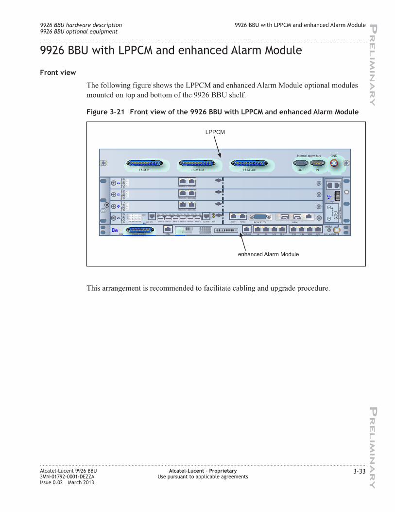
3-21 Front view of the 9926 BBU with LPPCM and enhanced Alarm Module ........................................ 3-333-33
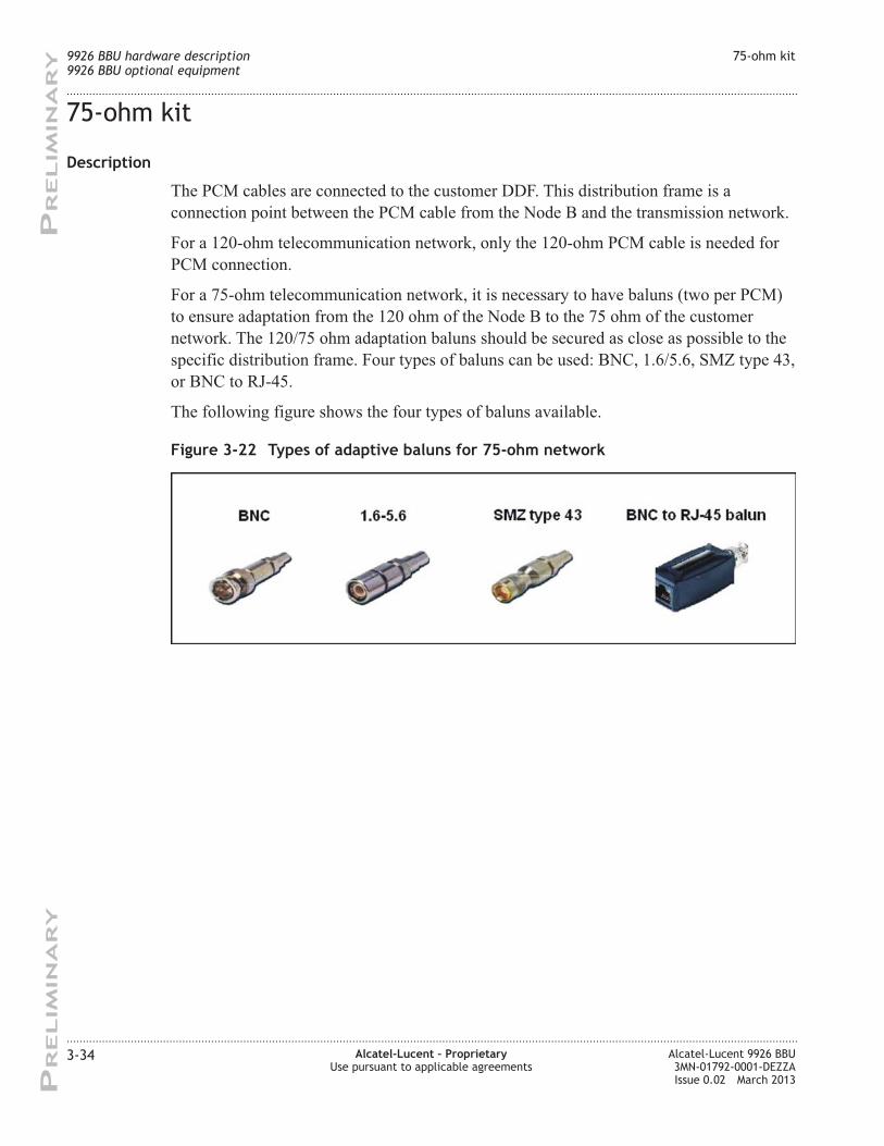
3-22 Types of adaptive baluns for 75-ohm network ............................................................................................. 3-343-34
List of figures
....................................................................................................................................................................................................................................
....................................................................................................................................................................................................................................
x Alcatel-Lucent – Proprietary
Use pursuant to applicable agreements
Alcatel-Lucent 9926 BBU
3MN-01792-0001-DEZZA
Issue 0.02 March 2013
PR
ELIM
IN
AR
YP
RELIM
IN
AR
Y
Page 11
About this documentAbout this document
Purpose
The purpose of this document is to describe the Alcatel-Lucent 9926 Base Band Unit
Node B for UMTS standard, based on d2UV3 rack. Its short name is the 9926 BBU.
For detailed information on the maintenance of the 9926 BBU , see Alcatel-Lucent 9926
Base Band Unit Node B - Maintenance Guide, 3MN-01792-0002-REZZA.
Reason for reissue
The reissue history of this document is shown in Appendix A, “Reference”
Intended audience
The audience for this document is Operations and maintenance personnel, and anyone
interested in learning more about the 9926 BBU.
Supported systems
This document applies to all Alcatel-Lucent W-CDMA system releases.
How to use this document
No specific recommendation applies regarding the way readers should read this
document.
Prerequisites
None
Conventions used
Vocabulary conventions
For a list of terms used in this document, see Alcatel-Lucent W-CDMA System -
Terminology, 9YZ-04088-0002-TQZZA.
...................................................................................................................................................................................................................................
Alcatel-Lucent 9926 BBU
3MN-01792-0001-DEZZA
Issue 0.02 March 2013
Alcatel-Lucent – Proprietary
Use pursuant to applicable agreements
xi
PR
ELIM
IN
AR
YP
RELIM
IN
AR
Y
Page 12
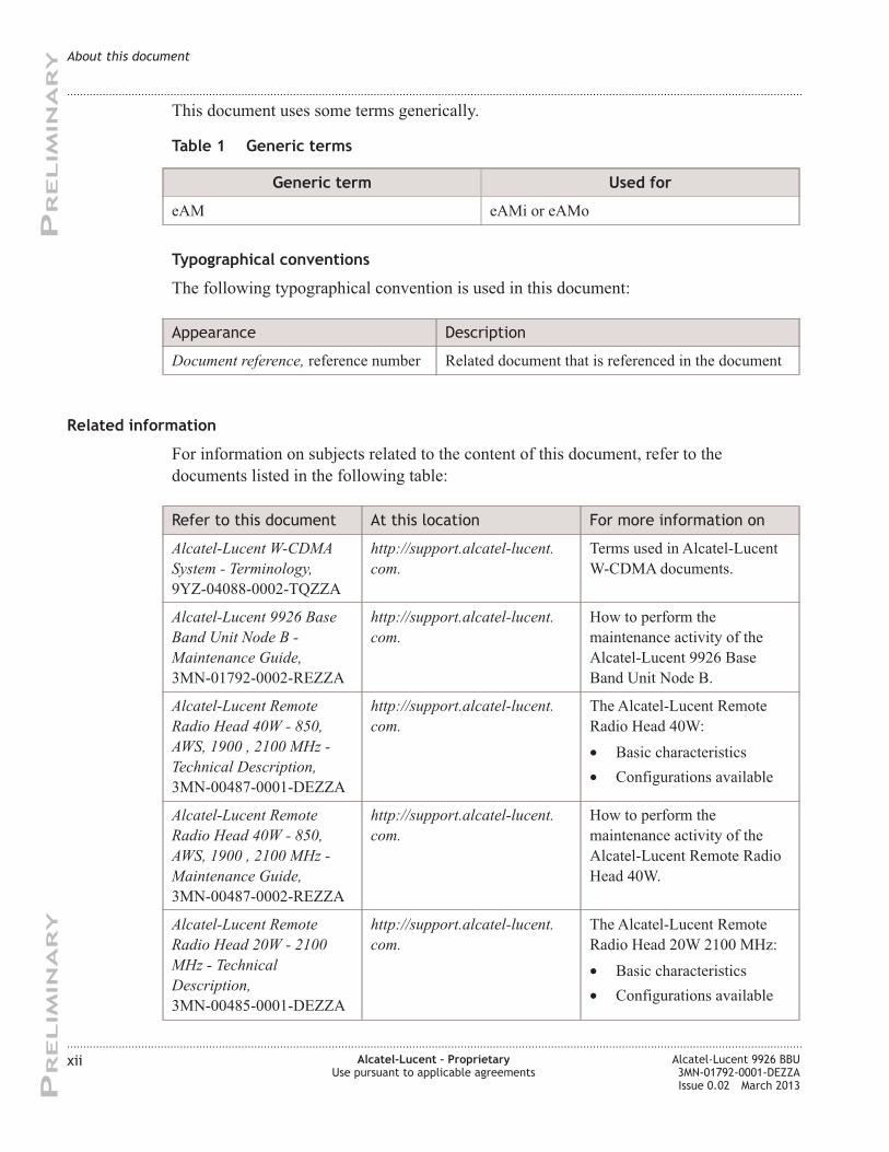
This document uses some terms generically.
Table 1 Generic terms
Generic term Used for
eAM eAMi or eAMo
Typographical conventions
The following typographical convention is used in this document:
Appearance Description
Document reference, reference number Related document that is referenced in the document
Related information
For information on subjects related to the content of this document, refer to the
documents listed in the following table:
Refer to this document At this location For more information on
Alcatel-Lucent W-CDMA
System - Terminology,
9YZ-04088-0002-TQZZA
http://support.alcatel-lucent.
com.
Terms used in Alcatel-Lucent
W-CDMA documents.
Alcatel-Lucent 9926 Base
Band Unit Node B -
Maintenance Guide,
3MN-01792-0002-REZZA
http://support.alcatel-lucent.
com.
How to perform the
maintenance activity of the
Alcatel-Lucent 9926 Base
Band Unit Node B.
Alcatel-Lucent Remote
Radio Head 40W - 850,
AWS, 1900 , 2100 MHz -
Technical Description,
3MN-00487-0001-DEZZA
http://support.alcatel-lucent.
com.
The Alcatel-Lucent Remote
Radio Head 40W:
• Basic characteristics
• Configurations available
Alcatel-Lucent Remote
Radio Head 40W - 850,
AWS, 1900 , 2100 MHz -
Maintenance Guide,
3MN-00487-0002-REZZA
http://support.alcatel-lucent.
com.
How to perform the
maintenance activity of the
Alcatel-Lucent Remote Radio
Head 40W.
Alcatel-Lucent Remote
Radio Head 20W - 2100
MHz - Technical
Description,
3MN-00485-0001-DEZZA
http://support.alcatel-lucent.
com.
The Alcatel-Lucent Remote
Radio Head 20W 2100 MHz:
• Basic characteristics
• Configurations available
About this document
....................................................................................................................................................................................................................................
....................................................................................................................................................................................................................................
xii Alcatel-Lucent – Proprietary
Use pursuant to applicable agreements
Alcatel-Lucent 9926 BBU
3MN-01792-0001-DEZZA
Issue 0.02 March 2013
PR
ELIM
IN
AR
YP
RELIM
IN
AR
Y
Page 13
Refer to this document At this location For more information on
Alcatel-Lucent Remote
Radio Head 20W - 2100
MHz- Maintenance Guide,
3MN-00485-0002-REZZA
http://support.alcatel-lucent.
com.
How to perform the
maintenance activity of the
Alcatel-Lucent Remote Radio
Head 20W.
Alcatel-Lucent 9353
Wireless Management
System - Node B Alarms
Reference Guide for 9311,
9312, 9322, 9326, 9332
Node B, 9YZ-04088-0060-
UFZZA
http://support.alcatel-lucent.
com.
Alarm descriptions and
maintenance actions required
for Alcatel-Lucent Node Bs.
Alcatel-Lucent 9100 and
93xx Node B –
Commissioning and Fault
Management User Manual:
TIL, NN-20500-019
http://support.alcatel-lucent.
com.
How to perform the Node B
installation, commissioning
and maintenance tasks using
the Node B TIL (Terminal for
Local Installation) tool.
Document support
For support in using this or any other Alcatel-Lucent document, contact Alcatel-Lucent at
one of the following telephone numbers:
• 1-888-582-3688 (for the United States)
• 1-630-224-2485 (for all other countries)
Technical support
For technical support, contact your local Alcatel-Lucent customer support team. See the
Alcatel-Lucent Support web site (http://www.alcatel-lucent.com/support/) for contact
information.
How to order
To order Alcatel-Lucent documents, contact your local sales representative or use Online
Customer Support (OLCS) (http://support.alcatel-lucent.com)
How to comment
To comment on this document, go to the Online Comment Form (http://infodoc.alcatel-
lucent.com/comments/) or e-mail your comments to the Comments Hotline
([email protected] ).
About this document
....................................................................................................................................................................................................................................
....................................................................................................................................................................................................................................
Alcatel-Lucent 9926 BBU
3MN-01792-0001-DEZZA
Issue 0.02 March 2013
Alcatel-Lucent – Proprietary
Use pursuant to applicable agreements
xiii
PR
ELIM
IN
AR
YP
RELIM
IN
AR
Y
Page 14
About this document
....................................................................................................................................................................................................................................
....................................................................................................................................................................................................................................
xiv Alcatel-Lucent – Proprietary
Use pursuant to applicable agreements
Alcatel-Lucent 9926 BBU
3MN-01792-0001-DEZZA
Issue 0.02 March 2013
PR
ELIM
IN
AR
YP
RELIM
IN
AR
Y
Page 15
1 1UTRAN introduction
Overview
Purpose
This chapter describes the Universal Mobile Telecommunications System (UMTS)
Terrestrial Radio Access Network (UTRAN).
Contents
UTRAN introduction 1-2
...................................................................................................................................................................................................................................
Alcatel-Lucent 9926 BBU
3MN-01792-0001-DEZZA
Issue 0.02 March 2013
Alcatel-Lucent – Proprietary
Use pursuant to applicable agreements
1-1
PR
ELIM
IN
AR
YP
RELIM
IN
AR
Y
Page 16
UTRAN introduction
UTRAN components
The UTRAN is composed of at least one Radio Network Subsystem (RNS). An RNS
covers a certain geographical area. It is equivalent to the GSM BSS. Each RNS is
composed of one Radio Network Controller (RNC) and one or more Node Bs. RNSs are
interconnected through the Iur interface of each RNC to form a network.
Alcatel-Lucent UTRAN
The Alcatel-Lucent UTRAN is based on the following components:
• RNC
• Node B
• WMS for the OAM part
RNC
The Alcatel-Lucent RNC is 3GPP-compliant. It is based on the Multiservice Switch
platform.
RNC main functions
The main functions of the RNC are to control and manage:
• Radio Access Network (RAN)
• Signalling between Core Network (CN) components and the Radio Network System
(RNS)
• Node Bs and their radio resources
RNC interfaces
The RNC provides the following interfaces:
• Iub towards a Node B
• Iu towards the Core Network
• Iur towards another RNC
• Iupc towards a Standalone A-GPS SMLC (SAS)
Node B
The Alcatel-Lucent Node Bs are 3GPP-compliant. The Alcatel-Lucent Node B portfolio
includes:
• Conventional unitary base stations
• Digital base stations
• Radio base stations
UTRAN introduction UTRAN introduction
....................................................................................................................................................................................................................................
....................................................................................................................................................................................................................................
1-2 Alcatel-Lucent – Proprietary
Use pursuant to applicable agreements
Alcatel-Lucent 9926 BBU
3MN-01792-0001-DEZZA
Issue 0.02 March 2013
PR
ELIM
IN
AR
YP
RELIM
IN
AR
Y
Page 17
• Radio heads
• Base station routers
Node B main functions
The Node B supports the following main functions:
• Network interface management
• Radio access
• Call processing
• Configuration and supervision
• Synchronization
• Performance monitoring
Node B interfaces
The Node B provides the following interfaces:
• Iub towards an RNC
• Uu towards a UE
• Interface B towards WMS
UTRAN introduction UTRAN introduction
....................................................................................................................................................................................................................................
....................................................................................................................................................................................................................................
Alcatel-Lucent 9926 BBU
3MN-01792-0001-DEZZA
Issue 0.02 March 2013
Alcatel-Lucent – Proprietary
Use pursuant to applicable agreements
1-3
PR
ELIM
IN
AR
YP
RELIM
IN
AR
Y
Page 18
WMS
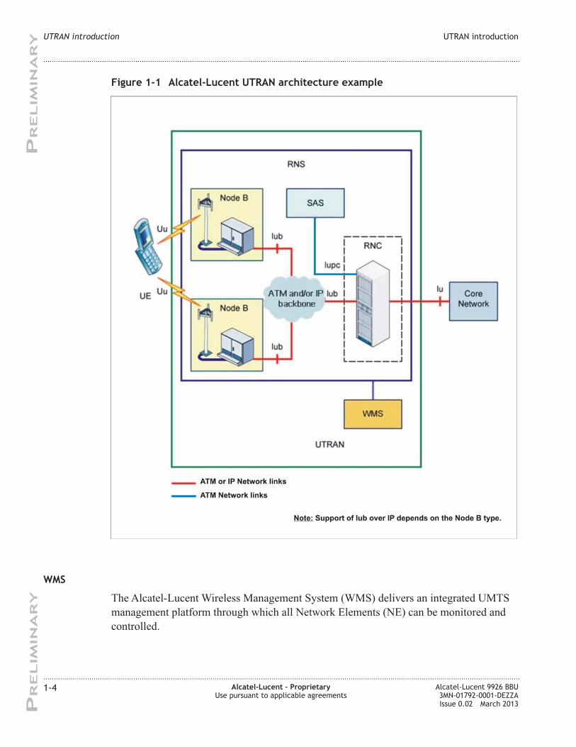
The Alcatel-Lucent Wireless Management System (WMS) delivers an integrated UMTS
management platform through which all Network Elements (NE) can be monitored and
controlled.
Figure 1-1 Alcatel-Lucent UTRAN architecture example
UTRAN introduction UTRAN introduction
....................................................................................................................................................................................................................................
....................................................................................................................................................................................................................................
1-4 Alcatel-Lucent – Proprietary
Use pursuant to applicable agreements
Alcatel-Lucent 9926 BBU
3MN-01792-0001-DEZZA
Issue 0.02 March 2013
PR
ELIM
IN
AR
YP
RELIM
IN
AR
Y
Page 19
It plays an important role in providing the foundation of a complete end-to-end
management solution for UMTS networks. The WMS manages the entire UMTS
network, which is divided into:
• The UTRAN
• The Core Network (circuit-switched and packet-switched traffics).
The Access Network OAM manages the UTRAN part of the network.
Access Network OAM main functions
The Access Network OAM manages the UTRAN part of the network.
The main functions of Access Network OAM are the following:
• Fault management
• Configuration management
• Performance management
NSP
The Network Services Platform (NSP) is a graphical user interface to the Access Network
providing a common platform for navigation and control. The NSP interfaces with the
NEs through a Common Object Request Broker Architecture (CORBA). This
vendor-independent architecture links computer applications across different networks.
UTRAN introduction UTRAN introduction
....................................................................................................................................................................................................................................
....................................................................................................................................................................................................................................
Alcatel-Lucent 9926 BBU
3MN-01792-0001-DEZZA
Issue 0.02 March 2013
Alcatel-Lucent – Proprietary
Use pursuant to applicable agreements
1-5
PR
ELIM
IN
AR
YP
RELIM
IN
AR
Y
Page 20
UTRAN introduction UTRAN introduction
....................................................................................................................................................................................................................................
....................................................................................................................................................................................................................................
1-6 Alcatel-Lucent – Proprietary
Use pursuant to applicable agreements
Alcatel-Lucent 9926 BBU
3MN-01792-0001-DEZZA
Issue 0.02 March 2013
PR
ELIM
IN
AR
YP
RELIM
IN
AR
Y
Page 21
2 29926 BBU basic
characteristics
Overview
Purpose
This chapter describes the basic characteristics of the 9926 BBU.
Contents
9926 BBU introduction 2-2
9926 BBU features and functions 2-4
9926 BBU external interfaces 2-7
9926 BBU optional features 2-11
9926 BBU physical and environmental characteristics 2-13
...................................................................................................................................................................................................................................
Alcatel-Lucent 9926 BBU
3MN-01792-0001-DEZZA
Issue 0.02 March 2013
Alcatel-Lucent – Proprietary
Use pursuant to applicable agreements
2-1
PR
ELIM
IN
AR
YP
RELIM
IN
AR
Y
Page 22
9926 BBU introduction
Introduction
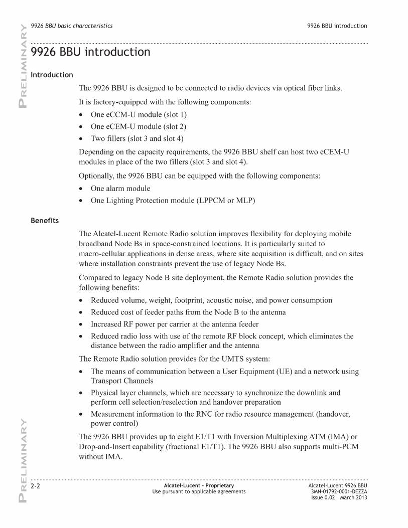
The 9926 BBU is designed to be connected to radio devices via optical fiber links.
It is factory-equipped with the following components:
• One eCCM-U module (slot 1)
• One eCEM-U module (slot 2)
• Two fillers (slot 3 and slot 4)
Depending on the capacity requirements, the 9926 BBU shelf can host two eCEM-U
modules in place of the two fillers (slot 3 and slot 4).
Optionally, the 9926 BBU can be equipped with the following components:
• One alarm module
• One Lighting Protection module (LPPCM or MLP)
Benefits
The Alcatel-Lucent Remote Radio solution improves flexibility for deploying mobile
broadband Node Bs in space-constrained locations. It is particularly suited to
macro-cellular applications in dense areas, where site acquisition is difficult, and on sites
where installation constraints prevent the use of legacy Node Bs.
Compared to legacy Node B site deployment, the Remote Radio solution provides the
following benefits:
• Reduced volume, weight, footprint, acoustic noise, and power consumption
• Reduced cost of feeder paths from the Node B to the antenna
• Increased RF power per carrier at the antenna feeder
• Reduced radio loss with use of the remote RF block concept, which eliminates the
distance between the radio amplifier and the antenna
The Remote Radio solution provides for the UMTS system:
• The means of communication between a User Equipment (UE) and a network using
Transport Channels
• Physical layer channels, which are necessary to synchronize the downlink and
perform cell selection/reselection and handover preparation
• Measurement information to the RNC for radio resource management (handover,
power control)
The 9926 BBU provides up to eight E1/T1 with Inversion Multiplexing ATM (IMA) or
Drop-and-Insert capability (fractional E1/T1). The 9926 BBU also supports multi-PCM
without IMA.
9926 BBU basic characteristics 9926 BBU introduction
....................................................................................................................................................................................................................................
....................................................................................................................................................................................................................................
2-2 Alcatel-Lucent – Proprietary
Use pursuant to applicable agreements
Alcatel-Lucent 9926 BBU
3MN-01792-0001-DEZZA
Issue 0.02 March 2013
PR
ELIM
IN
AR
YP
RELIM
IN
AR
Y
Page 23
The 9926 BBU delivers high UMTS radio performances and supports the enhanced High
Speed Downlink Packet Access (HSDPA) and High Speed Uplink Packet Access
(HSUPA) solutions through easy software upgrade.
The 9926 BBU is compliant with the Common Public Radio Interface (CPRI).
9926 BBU enclosure
The 9926 BBU provides the operators with a suited solution whatever the site constraints.
The 9926 BBU can be integrated:
• In a standalone indoor mode or in an existing indoor or outdoor Alcatel-Lucent 9100
Multi-Standard Base Station cabinet for multi-standard configuration
• In a small or a medium Power Supply Unit (PSU) outdoor cabinet
• In a 2G S8000 or S18000 Oudoor BTS cabinet
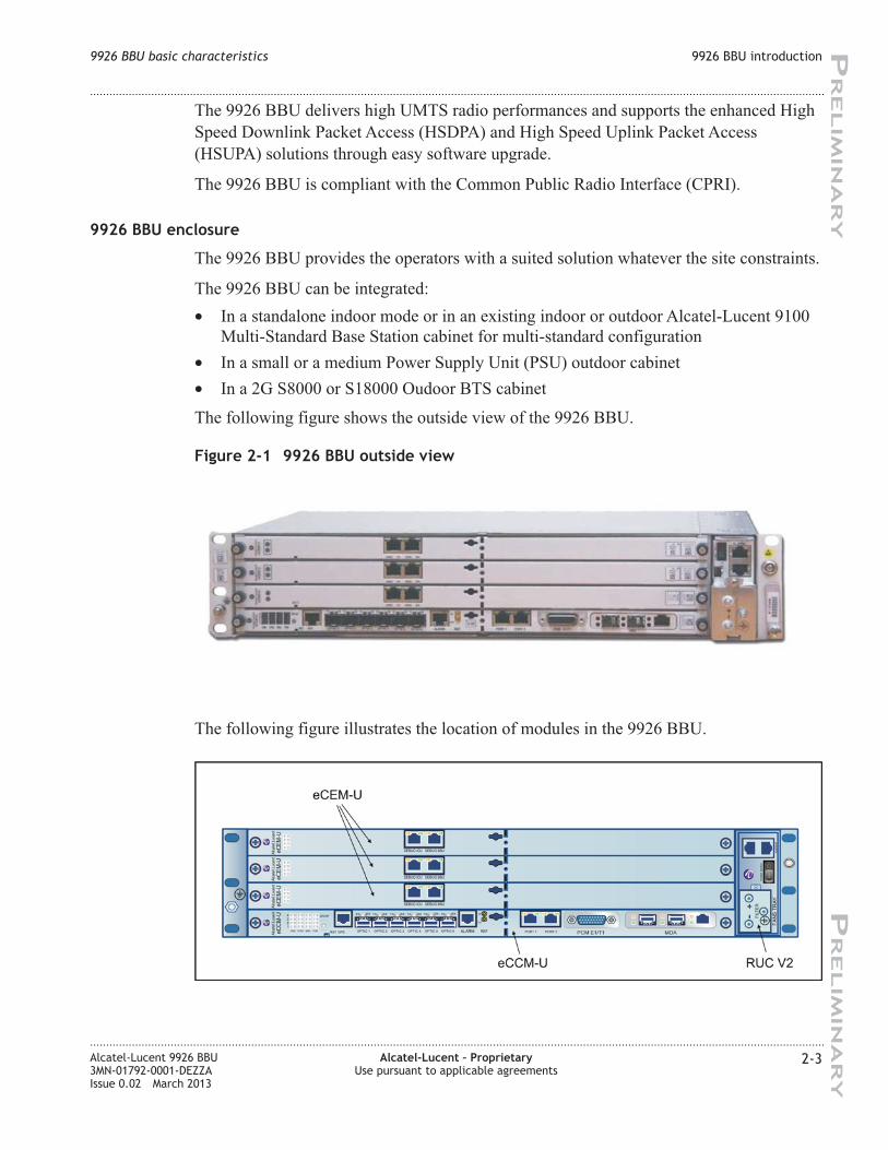
The following figure shows the outside view of the 9926 BBU.
The following figure illustrates the location of modules in the 9926 BBU.
Figure 2-1 9926 BBU outside view
9926 BBU basic characteristics 9926 BBU introduction
....................................................................................................................................................................................................................................
....................................................................................................................................................................................................................................
Alcatel-Lucent 9926 BBU
3MN-01792-0001-DEZZA
Issue 0.02 March 2013
Alcatel-Lucent – Proprietary
Use pursuant to applicable agreements
2-3
PR
ELIM
IN
AR
YP
RELIM
IN
AR
Y
Page 24
9926 BBU features and functions
Introduction
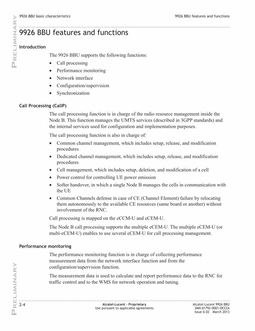
The 9926 BBU supports the following functions:
• Call processing
• Performance monitoring
• Network interface
• Configuration/supervision
• Synchronization
Call Processing (CallP)
The call processing function is in charge of the radio resource management inside the
Node B. This function manages the UMTS services (described in 3GPP standards) and
the internal services used for configuration and implementation purposes.
The call processing function is also in charge of:
• Common channel management, which includes setup, release, and modification
procedures
• Dedicated channel management, which includes setup, release, and modification
procedures
• Cell management, which includes setup, deletion, and modification of a cell
• Power control for controlling UE power emission
• Softer handover, in which a single Node B manages the cells in communication with
the UE
• Common Channels defense in case of CE (Channel Element) failure by relocating
them autonomously to the available CE resources (same board or another) without
involvement of the RNC.
Call processing is mapped on the eCCM-U and eCEM-U.
The Node B call processing supports the multiple eCEM-U. The multiple eCEM-U (or
multi-eCEM-U) enables to use several eCEM-U for call processing management.
Performance monitoring
The performance monitoring function is in charge of collecting performance
measurement data from the network interface function and from the
configuration/supervision function.
The measurement data is used to calculate and report performance data to the RNC for
traffic control and to the WMS for network operation and tuning.
9926 BBU basic characteristics 9926 BBU features and functions
....................................................................................................................................................................................................................................
....................................................................................................................................................................................................................................
2-4 Alcatel-Lucent – Proprietary
Use pursuant to applicable agreements
Alcatel-Lucent 9926 BBU
3MN-01792-0001-DEZZA
Issue 0.02 March 2013
PR
ELIM
IN
AR
YP
RELIM
IN
AR
Y
Page 25
Network interface
This function is in charge of managing interfaces with RNC.
The following network interfaces are supported:
• E1/T1 links with a layer 2 IMA machine handling up to four IMA groups, fractional
PCM (Drop-and-Insert capability), and redundancy management.
• Ethernet links
From LR13.1, 9926 BBU can be daisy-chained on the same Gigabit Ethernet backhaul
connection. For this it is necessary to use the eCCM-U-GE (with the GE MDA) using the
fiber optic SFP or built-in RJ45 ports.
Configuration/supervision
This function is in charge of:
• Module configuration and supervision
• Inventory information reporting
• Plug-and-play management
The remote inventory functionality provides the UMTS OAM access to determine the
inventory information of the Node B. The remote inventory is performed for the
following modules: eCEM-U, eCCM-U, fan tray and optional modules (alarm module,
lightning protection module).
Synchronization
This function is in charge of retrieving highly stable radio frequency from either network
interface or optional GPS receiver.
The 9926 BBU can be synchronized through the following means:
• E1/T1 PCM link (standard synchronization mechanism)
The E1/T1 link used for synchronization does not carry any data traffic.
• External GPS receiver
In the GPS-based synchronization solution, the eCCM-U module is connected to a
GPS smart antenna/receiver that provides GPS synchronization source (Pulse Per
Second (PPS) synchro input from the antenna).
• Integrated GPS receiver
Note: This synchronization mechanism is optionally available with the eCCM-U
module.
• IEEE 1588v2 Precision Time Protocol (PTP)
The PTP-based synchronization solution relies on time servers connected to the 9926
BBU through the Ethernet network.
Note: This synchronization mechanism only applies to native IP Node B .
• Synchronous Ethernet
9926 BBU basic characteristics 9926 BBU features and functions
....................................................................................................................................................................................................................................
....................................................................................................................................................................................................................................
Alcatel-Lucent 9926 BBU
3MN-01792-0001-DEZZA
Issue 0.02 March 2013
Alcatel-Lucent – Proprietary
Use pursuant to applicable agreements
2-5
PR
ELIM
IN
AR
YP
RELIM
IN
AR
Y
Page 26
Note: This synchronization mechanism only applies to native IP Node B .
9926 BBU basic characteristics 9926 BBU features and functions
....................................................................................................................................................................................................................................
....................................................................................................................................................................................................................................
2-6 Alcatel-Lucent – Proprietary
Use pursuant to applicable agreements
Alcatel-Lucent 9926 BBU
3MN-01792-0001-DEZZA
Issue 0.02 March 2013
PR
ELIM
IN
AR
YP
RELIM
IN
AR
Y
Page 27
9926 BBU external interfaces
Introduction
The 9926 BBU is equipped with four main types of external interface:
• E1/T1 and/or IP network interface (Iub)
• Optical interface to radio devices
• Alarm/remote control interface (optional)
• Power supply interface (DC input)
Interface location
The following diagrams show the locations of the interfaces on the 9926 BBU.
The GE MDA provides three GE ports: two are optical using SFPs, the third is an
electrical GE interface. The SFP2 and electrical interface are, however, the same logical
port and so only one can be used.
Figure 2-2 9926 BBU with eCCM-U-GE
FIL
TE
R
+-
PO
WE
RS
WIT
CH
ALA
RM
/IN
TFA
NS
TR
AY
SYNC MDA PCMPCM E1/T1ALARM REF MDAPORT 1 PORT 2OPTIC 6OPTIC 5OPTIC 4OPTIC 3OPTIC 2OPTIC 1GPS
GPS-RF
RST
TX RX TX RX TX RX TX RX TX RX TX RX
CMA
12
34
IN
OUT
eC
CM
-UA
lcate
l.Luce
nt
DEBUG ICU DEBUG BBUeC
EM
-UA
lcate
l.Luce
nt
DEBUG ICU DEBUG BBUeC
EM
-UA
lcate
l.Luce
nt
DEBUG ICU DEBUG BBUeC
EM
-UA
lcate
l.Luce
nt
RUC V2eCCM-U
eCEM-U #1
eCEM-U #2
eCEM-U #3
IubE1/T1(4)
IubIP(GE)
IubIP(FE)CPRI Alarms
MDA-GE
9926 BBU basic characteristics 9926 BBU external interfaces
....................................................................................................................................................................................................................................
....................................................................................................................................................................................................................................
Alcatel-Lucent 9926 BBU
3MN-01792-0001-DEZZA
Issue 0.02 March 2013
Alcatel-Lucent – Proprietary
Use pursuant to applicable agreements
2-7
PR
ELIM
IN
AR
YP
RELIM
IN
AR
Y
Page 28
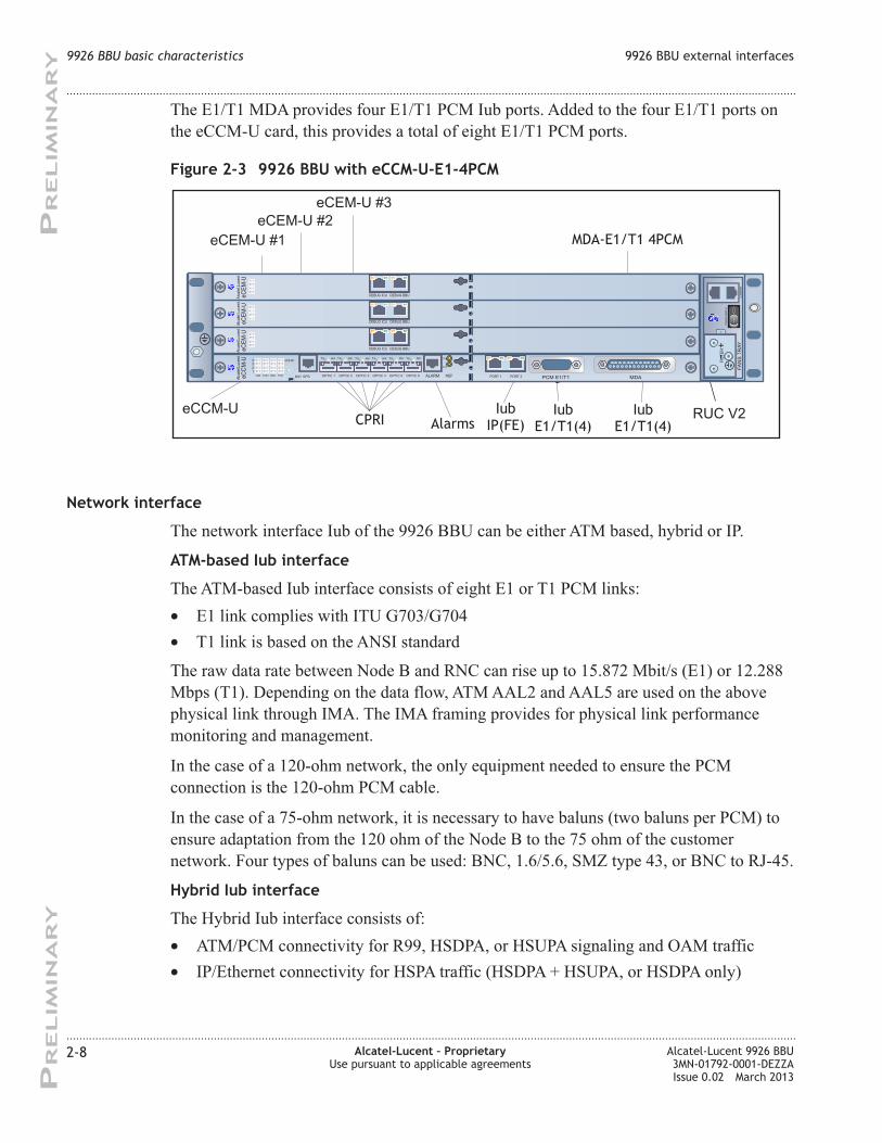
The E1/T1 MDA provides four E1/T1 PCM Iub ports. Added to the four E1/T1 ports on
the eCCM-U card, this provides a total of eight E1/T1 PCM ports.
Network interface
The network interface Iub of the 9926 BBU can be either ATM based, hybrid or IP.
ATM-based Iub interface
The ATM-based Iub interface consists of eight E1 or T1 PCM links:
• E1 link complies with ITU G703/G704
• T1 link is based on the ANSI standard
The raw data rate between Node B and RNC can rise up to 15.872 Mbit/s (E1) or 12.288
Mbps (T1). Depending on the data flow, ATM AAL2 and AAL5 are used on the above
physical link through IMA. The IMA framing provides for physical link performance
monitoring and management.
In the case of a 120-ohm network, the only equipment needed to ensure the PCM
connection is the 120-ohm PCM cable.
In the case of a 75-ohm network, it is necessary to have baluns (two baluns per PCM) to
ensure adaptation from the 120 ohm of the Node B to the 75 ohm of the customer
network. Four types of baluns can be used: BNC, 1.6/5.6, SMZ type 43, or BNC to RJ-45.
Hybrid Iub interface
The Hybrid Iub interface consists of:
• ATM/PCM connectivity for R99, HSDPA, or HSUPA signaling and OAM traffic
• IP/Ethernet connectivity for HSPA traffic (HSDPA + HSUPA, or HSDPA only)
Figure 2-3 9926 BBU with eCCM-U-E1-4PCM
FIL
TE
R
+-
PO
WE
RS
WIT
CH
ALA
RM
/IN
TFA
NS
TR
AY
SYNC MDA PCMPCM E1/T1ALARM REF MDAPORT 1 PORT 2OPTIC 6OPTIC 5OPTIC 4OPTIC 3OPTIC 2OPTIC 1GPS
GPS-RF
RST
TX RX TX RX TX RX TX RX TX RX TX RX
CMA
12
34
IN
OUT
eC
CM
-UA
lcate
l.Luce
nt
DEBUG ICU DEBUG BBUeC
EM
-UA
lcate
l.Luce
nt
DEBUG ICU DEBUG BBUeC
EM
-UA
lcate
l.Luce
nt
DEBUG ICU DEBUG BBUeC
EM
-UA
lcate
l.Luce
nt
RUC V2eCCM-U
eCEM-U #1
eCEM-U #2
eCEM-U #3
IubE1/T1(4)
IubE1/T1(4)
IubIP(FE)CPRI Alarms
MDA-E1/T1 4PCM
9926 BBU basic characteristics 9926 BBU external interfaces
....................................................................................................................................................................................................................................
....................................................................................................................................................................................................................................
2-8 Alcatel-Lucent – Proprietary
Use pursuant to applicable agreements
Alcatel-Lucent 9926 BBU
3MN-01792-0001-DEZZA
Issue 0.02 March 2013
PR
ELIM
IN
AR
YP
RELIM
IN
AR
Y
Page 29
The Hybrid Iub interface requires the eCCM-U module in “eCCM-U-E1-4PCM” or
“eCCM-U-GE” hardware configuration.
The Hybrid Iub can use one of these options:
• Optical GE via one SFP GE port of the GE MDA
• Electrical GE via the RJ45 connector on the GE MDA
• FE via Port 2 of the eCCM-U
The native IP Iub interface requires the “eCCM-U-GE” hardware configuration.
Native IP Iub interface
The native IP Iub interface consists of a full IP/Ethernet transport on Iub interface. When
native IP Iub feature is deployed, the ATM/PCM connectivity is no longer used for the
Iub.
BTS daisy-chaining
From LR13.1, BTS daisy-chaining allows one GE link to serve a number of
Alcatel-Lucent base stations. The base stations can be multi-generation of 2G, 3G or 4G.
The number of base stations is limited to 1 Gb/s of the GE link, or by the capacity of the
switch in the most upstream base station of the chain.
When a base station A is located upstream in the daisy chain with respect to the position
of another base station B, it is called a ‘Chaining BTS’ or a ‘Dropping BTS’. BTS B is
called a ‘Chained BTS’ or a ‘Dropped BTS’.
In this system release the validated configurations are
• 3G chaining to 3G chained
• 3G chaining to 4G chained using IPV4
• 3G chaining to 4G chained using IPV6
• 3G chaining to 4G chained using IPV4 with IPSEC
A 9926 BBU can be used for daisy chaining once the software is upgraded in the 9926
BBU. The feature can be activated without the need to reset the dropping Node B to
activate the feature.
BTS daisy-chaining uses only the GE ports on the GE MDA on the eCCM-U-GE. Fiber
port SFP2 and the RJ45 port are internally connected and so cannot be use
simultaneously, so one of these ports is used in conjunction with the SFP1 fiber port.
The BTS daisy-chaining also carries time/clock synchronization using Synchronous
Ethernet protocol or IEEE 1588v2. The synchronization data may be generated by the
backhaul. Alternatively, any Node B in the chain can be configured to get synchronization
from an external synchronization source and propagate the synchronization data
downstream only via the daisy-chain. Note that only fiber SFPs and the RJ45 port can
propagate SyncE: copper SFPs do not support this feature.
9926 BBU basic characteristics 9926 BBU external interfaces
....................................................................................................................................................................................................................................
....................................................................................................................................................................................................................................
Alcatel-Lucent 9926 BBU
3MN-01792-0001-DEZZA
Issue 0.02 March 2013
Alcatel-Lucent – Proprietary
Use pursuant to applicable agreements
2-9
PR
ELIM
IN
AR
YP
RELIM
IN
AR
Y
Page 30
Ethernet OAM is supported on the BTS daisy-chain to provide different levels of link and
fault monitoring:
• CFM
Connectivity Fault monitoring IEEE 802.1ag is supported for the Chaining BTS and
provides:
– Hierarchical view with customer, provider and operator domains
– path discovery
– fault detection
– fault verification and isolation (Loopback)
– fault notification
– fault recovery
• ITU-T Y1731
ITU-T Y1731 provides:
– fault notification
– performance management.
CPRI optical interface
The CPRI optical interface consists of up to six optical fiber ports, which can support
connection of to up to six radio devices.
Alarm/remote control interface (optional)
Optionally, one of the following interfaces is provided:
• Connectivity for 16 external alarms and six remote controls. This option includes
lightning protection.
• Connectivity for 32 external alarms.
Power supply interface
The 9926 BBU provides cable entry for – 48 VDC power.
9926 BBU basic characteristics 9926 BBU external interfaces
....................................................................................................................................................................................................................................
....................................................................................................................................................................................................................................
2-10 Alcatel-Lucent – Proprietary
Use pursuant to applicable agreements
Alcatel-Lucent 9926 BBU
3MN-01792-0001-DEZZA
Issue 0.02 March 2013
PR
ELIM
IN
AR
YP
RELIM
IN
AR
Y
Page 31
9926 BBU optional features
Introduction
The 9926 BBU supports the following optional components:
• The PCM Lightning Protection kit (LPPCM / MLP box)
This kit provides lightning protection for the PCM links. It requires a 1U additional
free space.
• The External Alarm kit
One of the two following modules can be used according to the number of external
alarms to be monitored:
– The External Alarm module provides the connection of 16 external alarms. It
requires a 1U additional free space.
– The enhanced Alarm Module (eAM) provides the connection of 32 external
alarms. It requires a 1/2 U additional free space.
• The 75-ohm kit
This list is not exhaustive. In particular, this document does not provide information on
ancillaries (cables and installation kits).
9926 BBU view with optional equipment
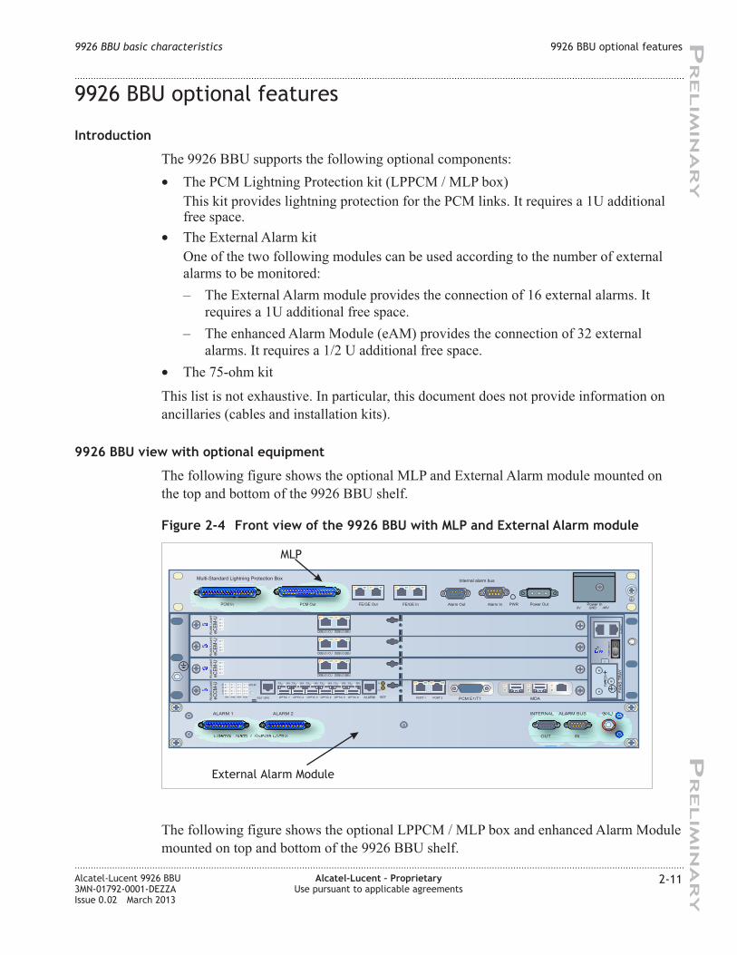
The following figure shows the optional MLP and External Alarm module mounted on
the top and bottom of the 9926 BBU shelf.
The following figure shows the optional LPPCM / MLP box and enhanced Alarm Module
mounted on top and bottom of the 9926 BBU shelf.
Figure 2-4 Front view of the 9926 BBU with MLP and External Alarm module
Multi-Standard Lightning Protection BoxInternal alarm bus
PCM In PCM Out Alarm Out Alarm InFE/GE Out FE/GE In PWR Power Out Power In0V GND -48V
FIL
TE
R
+-
PO
WE
RS
WIT
CH
ALA
RM
/IN
TFA
NS
TR
AY
SYNC MDA PCMPCM E1/T1ALARM REF MDAPORT 1 PORT 2OPTIC 6OPTIC 5OPTIC 4OPTIC 3OPTIC 2OPTIC 1GPS
GPS-RF
RST
TX RX TX RX TX RX TX RX TX RX TX RX
CMA
12
34
IN
OUT
eC
CM
-UA
lcate
l.Luce
nt
DEBUG ICU DEBUG BBUeC
EM
-UA
lcate
l.Luce
nt
DEBUG ICU DEBUG BBUeC
EM
-UA
lcate
l.Luce
nt
DEBUG ICU DEBUG BBUeC
EM
-UA
lcate
l.Luce
nt
ALARM 1 ALARM 2
External Alarm / Remote Control
INTERNAL ALARM BUS
OUT IN
GND
External Alarm Module
MLP
9926 BBU basic characteristics 9926 BBU optional features
....................................................................................................................................................................................................................................
....................................................................................................................................................................................................................................
Alcatel-Lucent 9926 BBU
3MN-01792-0001-DEZZA
Issue 0.02 March 2013
Alcatel-Lucent – Proprietary
Use pursuant to applicable agreements
2-11
PR
ELIM
IN
AR
YP
RELIM
IN
AR
Y
Page 32
Figure 2-5 Front view of the 9926 BBU with LPPCM and enhanced Alarm Module
Internal alarm bus
OUT IN
GND
PCM In PCM Out PCM Out
FIL
TE
R
+-
PO
WE
RS
WIT
CH
AL
AR
M/I
NT
FA
NS
TR
AY
SYNC MDA PCMPCM E1/T1ALARM REF MDAPORT 1 PORT 2OPTIC 6OPTIC 5OPTIC 4OPTIC 3OPTIC 2OPTIC 1GPS
GPS-RF
RST
TX RX TX RX TX RX TX RX TX RX TX RX
CMA
12
34
IN
OUT
eC
CM
-UA
lcate
l.Luce
nt
DEBUG ICU DEBUG BBUeC
EM
-UA
lcate
l.Luce
nt
DEBUG ICU DEBUG BBUeC
EM
-UA
lcate
l.Luce
nt
DEBUG ICU DEBUG BBUeC
EM
-UA
lcate
l.Luce
nt
STAT PWR ALM
XXXXXXXXXXXX
FRAME ALARMS CTRLSN XXXXXXXXXX
XXXXXXXXXXXXXXXXXXXXXXXXXXXXXXXXXXXX
XXXXXXXXXXXX
1-4 5-8 9-12 13-16 17-20 21-24 25-28 29-32 EXT ALARMS
eAMi
LPPCM
enhanced Alarm Module
9926 BBU basic characteristics 9926 BBU optional features
....................................................................................................................................................................................................................................
....................................................................................................................................................................................................................................
2-12 Alcatel-Lucent – Proprietary
Use pursuant to applicable agreements
Alcatel-Lucent 9926 BBU
3MN-01792-0001-DEZZA
Issue 0.02 March 2013
PR
ELIM
IN
AR
YP
RELIM
IN
AR
Y
Page 33
9926 BBU physical and environmental characteristics
Dimension and weight
The 9926 BBU rack has the following characteristics:
• Width (W): 482.6 mm
• Depth (D): 300 mm
• Height (H): 88.1 mm
• Weight (fully equipped): from 9.8 kg up to 10.5 kg (depending on the number of
eCEM-U in the digital shelf)
The 9926 BBU is designed to support an external temperature range of –5°C to +65°C,
with an absolute humidity between 1 g/m3
and 29 g/m3.
9926 BBU basic characteristics 9926 BBU physical and environmental characteristics
....................................................................................................................................................................................................................................
....................................................................................................................................................................................................................................
Alcatel-Lucent 9926 BBU
3MN-01792-0001-DEZZA
Issue 0.02 March 2013
Alcatel-Lucent – Proprietary
Use pursuant to applicable agreements
2-13
PR
ELIM
IN
AR
YP
RELIM
IN
AR
Y
Page 34
9926 BBU basic characteristics 9926 BBU physical and environmental characteristics
....................................................................................................................................................................................................................................
....................................................................................................................................................................................................................................
2-14 Alcatel-Lucent – Proprietary
Use pursuant to applicable agreements
Alcatel-Lucent 9926 BBU
3MN-01792-0001-DEZZA
Issue 0.02 March 2013
PR
ELIM
IN
AR
YP
RELIM
IN
AR
Y
Page 35
3 39926 BBU hardware
description
Overview
Purpose
The 9926 BBU is built around the following components:
• A mechanical enclosure compatible with standard 19-inch rack installation
• A digital shelf including the digital modules (eCCM-U, eCEM-U) and the associated
digital backplane
• A fans tray (including one RUC and two fans) located on the right hand side of the
digital shelf.
In addition, the 9926 BBU is equipped with the following two components:
• An external alarm module
• A lighting protection module (LPPCM or MLP box)
9926 BBU view
The following figure shows the outside view of the 9926 BBU.
The following figures illustrate the location of modules in the 9926 BBU.
Figure 3-1 9926 BBU outside view
...................................................................................................................................................................................................................................
Alcatel-Lucent 9926 BBU
3MN-01792-0001-DEZZA
Issue 0.02 March 2013
Alcatel-Lucent – Proprietary
Use pursuant to applicable agreements
3-1
PR
ELIM
IN
AR
YP
RELIM
IN
AR
Y
Page 36
Contents
9926 BBU digital shelf 3-3
9926 BBU digital shelf modules 3-4
enhanced Channel Element Module-U (eCEM-U) 3-8
enhanced Core Controller Module-U (eCCM-U) 3-11
9926 BBU fans tray (48V) 3-17
9926 BBU fan tray (48V) 3-18
Rack User Commissioning (RUC) module 3-20
9926 BBU optional equipment 3-22
External Alarm module 3-23
enhanced Alarm Module (eAM) 3-26
PCM Lightning Protection (LPPCM) module 3-29
Multi-standard Lightning Protection (MLP) box 3-30
9926 BBU with LPPCM and External Alarm modules 3-32
9926 BBU with LPPCM and enhanced Alarm Module 3-33
75-ohm kit 3-34
Figure 3-2 Location of modules in the 9926 BBU
9926 BBU hardware description Overview
....................................................................................................................................................................................................................................
....................................................................................................................................................................................................................................
3-2 Alcatel-Lucent – Proprietary
Use pursuant to applicable agreements
Alcatel-Lucent 9926 BBU
3MN-01792-0001-DEZZA
Issue 0.02 March 2013
PR
ELIM
IN
AR
YP
RELIM
IN
AR
Y
Page 37
9926 BBU digital shelf
Overview
Purpose
This section describes the modules housed in the 9926 BBU digital shelf.
Contents
9926 BBU digital shelf modules 3-4
enhanced Channel Element Module-U (eCEM-U) 3-8
enhanced Core Controller Module-U (eCCM-U) 3-11
9926 BBU hardware description
9926 BBU digital shelf
Overview
....................................................................................................................................................................................................................................
....................................................................................................................................................................................................................................
Alcatel-Lucent 9926 BBU
3MN-01792-0001-DEZZA
Issue 0.02 March 2013
Alcatel-Lucent – Proprietary
Use pursuant to applicable agreements
3-3
PR
ELIM
IN
AR
YP
RELIM
IN
AR
Y
Page 38
9926 BBU digital shelf modules
Introduction
The 9926 BBU digital shelf contains the following equipment:
• A four-slot digital shelf equipped with two types of hardware modules
• A fans tray
• A backplane supporting all the links between these modules.
Backplane functionality
The backplane is part of the digital shelf. It is in charge of supporting all internal links
and electrical interfaces between the modules of the digital shelf. All modules and some
cables carrying external signals are plugged into connectors mounted on the backplane
Printed-Circuit Board (PCB). The backplane board accommodates several high-speed
signals up to 1.3 Gbit/s. It supports -48 V DC power supply.
The digital backplane provides:
• Inter-module connections
• –48 V DC
The digital backplane used in the 9926 BBU is the Rack BackPlane (RBP).
The following figure illustrates the 9926 BBU RBP.
The following figure shows the RBP in the pre-cabled 9926 BBU rack.
Figure 3-3 9926 BBU RBP
9926 BBU hardware description
9926 BBU digital shelf
9926 BBU digital shelf modules
....................................................................................................................................................................................................................................
....................................................................................................................................................................................................................................
3-4 Alcatel-Lucent – Proprietary
Use pursuant to applicable agreements
Alcatel-Lucent 9926 BBU
3MN-01792-0001-DEZZA
Issue 0.02 March 2013
PR
ELIM
IN
AR
YP
RELIM
IN
AR
Y
Page 39
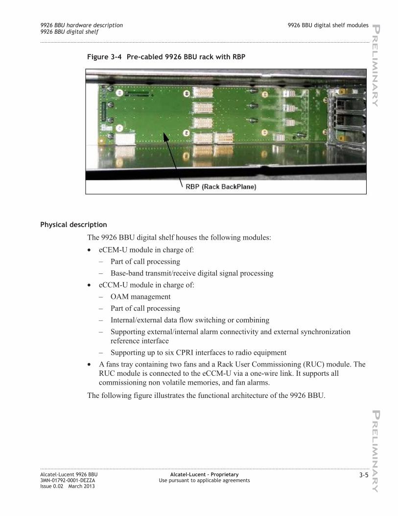
Physical description
The 9926 BBU digital shelf houses the following modules:
• eCEM-U module in charge of:
– Part of call processing
– Base-band transmit/receive digital signal processing
• eCCM-U module in charge of:
– OAM management
– Part of call processing
– Internal/external data flow switching or combining
– Supporting external/internal alarm connectivity and external synchronization
reference interface
– Supporting up to six CPRI interfaces to radio equipment
• A fans tray containing two fans and a Rack User Commissioning (RUC) module. The
RUC module is connected to the eCCM-U via a one-wire link. It supports all
commissioning non volatile memories, and fan alarms.
The following figure illustrates the functional architecture of the 9926 BBU.
Figure 3-4 Pre-cabled 9926 BBU rack with RBP
9926 BBU hardware description
9926 BBU digital shelf
9926 BBU digital shelf modules
....................................................................................................................................................................................................................................
....................................................................................................................................................................................................................................
Alcatel-Lucent 9926 BBU
3MN-01792-0001-DEZZA
Issue 0.02 March 2013
Alcatel-Lucent – Proprietary
Use pursuant to applicable agreements
3-5
PR
ELIM
IN
AR
YP
RELIM
IN
AR
Y
Page 40
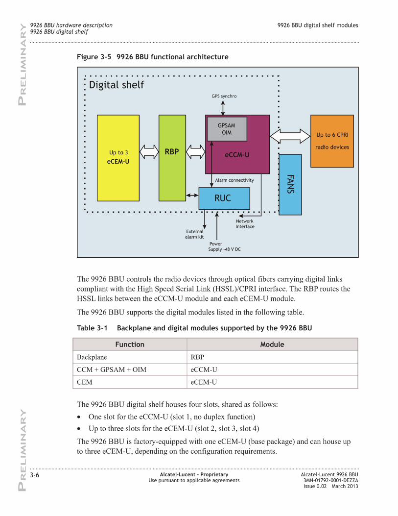
The 9926 BBU controls the radio devices through optical fibers carrying digital links
compliant with the High Speed Serial Link (HSSL)/CPRI interface. The RBP routes the
HSSL links between the eCCM-U module and each eCEM-U module.
The 9926 BBU supports the digital modules listed in the following table.
Table 3-1 Backplane and digital modules supported by the 9926 BBU
Function Module
Backplane RBP
CCM + GPSAM + OIM eCCM-U
CEM eCEM-U
The 9926 BBU digital shelf houses four slots, shared as follows:
• One slot for the eCCM-U (slot 1, no duplex function)
• Up to three slots for the eCEM-U (slot 2, slot 3, slot 4)
The 9926 BBU is factory-equipped with one eCEM-U (base package) and can house up
to three eCEM-U, depending on the configuration requirements.
Figure 3-5 9926 BBU functional architecture
9926 BBU hardware description
9926 BBU digital shelf
9926 BBU digital shelf modules
....................................................................................................................................................................................................................................
....................................................................................................................................................................................................................................
3-6 Alcatel-Lucent – Proprietary
Use pursuant to applicable agreements
Alcatel-Lucent 9926 BBU
3MN-01792-0001-DEZZA
Issue 0.02 March 2013
PR
ELIM
IN
AR
YP
RELIM
IN
AR
Y
Page 41
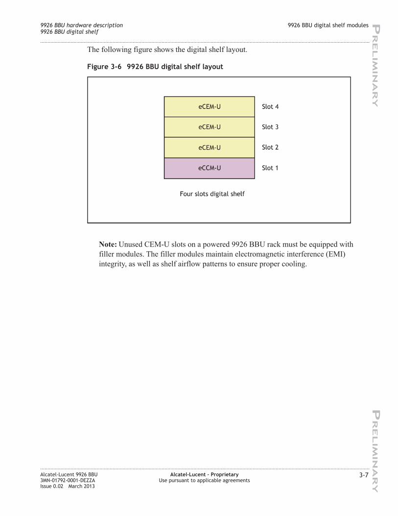
The following figure shows the digital shelf layout.
Note: Unused CEM-U slots on a powered 9926 BBU rack must be equipped with
filler modules. The filler modules maintain electromagnetic interference (EMI)
integrity, as well as shelf airflow patterns to ensure proper cooling.
Figure 3-6 9926 BBU digital shelf layout
9926 BBU hardware description
9926 BBU digital shelf
9926 BBU digital shelf modules
....................................................................................................................................................................................................................................
....................................................................................................................................................................................................................................
Alcatel-Lucent 9926 BBU
3MN-01792-0001-DEZZA
Issue 0.02 March 2013
Alcatel-Lucent – Proprietary
Use pursuant to applicable agreements
3-7
PR
ELIM
IN
AR
YP
RELIM
IN
AR
Y
Page 42
enhanced Channel Element Module-U (eCEM-U)
Main functions
The eCEM-U performs the same function as the xCEM-U.
However, it embarks hardware improvements that support the higher capacity required
for MIMO and HSPA+ features.
The eCEM-U performs the baseband radio signal processing and part of the call
processing.
The eCEM-U supports up to:
• 256 UMTS voice channels
• 128 HSPA channels
The eCEM-U performs both uplink and downlink traffic processing with both Rx and Tx
diversity with no capacity loss.
The processing function includes the following:
• Rx signal processing (de-correlation, finger processing, MRC, search,
de-multiplexing, de-interleaving and decoding)
• Tx signal processing (coding interleaving, channel multiplexing, spreading, summing
and power weighting)
The eCEM-U supports the softer handover feature across up to six sectors.
The eCEM-U also manages the traffic network interface for ATM termination and data
scheduling for the HSDPA/E-DCH support.
The eCEM-U handles call processing functions along with OAM operations.
Hardware description
The eCEM-U is composed of:
• One main board (size 389.6mm x 274.8mm)
• One front panel
All the eCEM-U interfaces are located at the rear of the module and connected to the
RBP. The front panel only includes LEDs and debug interfaces.
The following figure shows the eCEM-U front panel.
9926 BBU hardware description
9926 BBU digital shelf
enhanced Channel Element Module-U (eCEM-U)
....................................................................................................................................................................................................................................
....................................................................................................................................................................................................................................
3-8 Alcatel-Lucent – Proprietary
Use pursuant to applicable agreements
Alcatel-Lucent 9926 BBU
3MN-01792-0001-DEZZA
Issue 0.02 March 2013
PR
ELIM
IN
AR
YP
RELIM
IN
AR
Y
Page 43
Port description
The eCEM-U front panel has the following connectors:
• One Debug Ethernet connector (RJ-45 type connector) for synchronization of test
equipment (labeled “DEBUG ICU”)
• One Sync connector (RJ-45 type connector) (labeled “DEBUG BBU”)
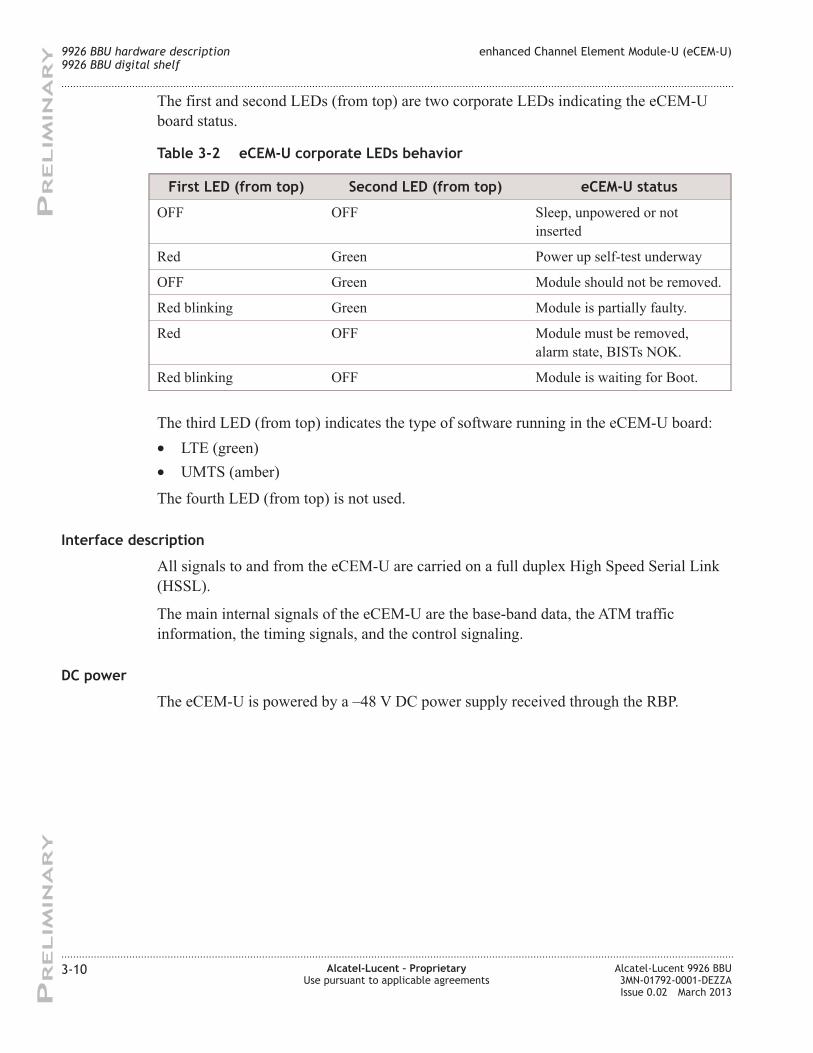
These two RJ-45 connectors are not used in normal operation.
LED description
The eCEM-U front panel has four tri-color (green/amber/red) LEDs as illustrated in the
following figure:
Figure 3-7 eCEM-U front panel
Figure 3-8 eCEM-U tri-color LEDs
9926 BBU hardware description
9926 BBU digital shelf
enhanced Channel Element Module-U (eCEM-U)
....................................................................................................................................................................................................................................
....................................................................................................................................................................................................................................
Alcatel-Lucent 9926 BBU
3MN-01792-0001-DEZZA
Issue 0.02 March 2013
Alcatel-Lucent – Proprietary
Use pursuant to applicable agreements
3-9
PR
ELIM
IN
AR
YP
RELIM
IN
AR
Y
Page 44
The first and second LEDs (from top) are two corporate LEDs indicating the eCEM-U
board status.
Table 3-2 eCEM-U corporate LEDs behavior
First LED (from top) Second LED (from top) eCEM-U status
OFF OFF Sleep, unpowered or not
inserted
Red Green Power up self-test underway
OFF Green Module should not be removed.
Red blinking Green Module is partially faulty.
Red OFF Module must be removed,
alarm state, BISTs NOK.
Red blinking OFF Module is waiting for Boot.
The third LED (from top) indicates the type of software running in the eCEM-U board:
• LTE (green)
• UMTS (amber)
The fourth LED (from top) is not used.
Interface description
All signals to and from the eCEM-U are carried on a full duplex High Speed Serial Link
(HSSL).
The main internal signals of the eCEM-U are the base-band data, the ATM traffic
information, the timing signals, and the control signaling.
DC power
The eCEM-U is powered by a –48 V DC power supply received through the RBP.
9926 BBU hardware description
9926 BBU digital shelf
enhanced Channel Element Module-U (eCEM-U)
....................................................................................................................................................................................................................................
....................................................................................................................................................................................................................................
3-10 Alcatel-Lucent – Proprietary
Use pursuant to applicable agreements
Alcatel-Lucent 9926 BBU
3MN-01792-0001-DEZZA
Issue 0.02 March 2013
PR
ELIM
IN
AR
YP
RELIM
IN
AR
Y
Page 45
enhanced Core Controller Module-U (eCCM-U)
Main functions
The eCCM-U aggregates the following three functions:
• Core Controller (CCM) function:
– Iub interface
– Call processing
– Data switching and routing
– OAM management
– Node B frequency and timing reference
• Global Positioning System and Alarm (GPSAM) function:
– External/internal alarm connectivity
– External GPS synchronization reference interface
– Integrated GPS receiver (optional)
• Optical Interface (OIM) function:
– Six ports support connection of up to six radio devices (TRDU, RRH, MC-TRX),
or connection of more than six radio devices using several modules in daisy
chaining (TRDU60W variant or RRH)
– Physical interface supported by six Small Form-factor Pluggable (SFP) compliant
connections: optical SFPs of Multi-Mode (MM) (850 nm) or Single-Mode (SM)
(TX 1550 nm, RX 1310 nm) type support optical fibre links.
For short intra-cabinet connections, the SFPs and fibre can be replaced by
electrical CPRI cables that plug directly into the SFP cage in place of the SFP.
– Support of CPRI rates 2 (1.2288 Gb/s) and 3 (2.4576 Gb/s) on all six optical ports.
Optical ports 4 to 6 also support HSSL as an alternative.
See “Connectivity with MC-TRX module” later in this chapter for special
considerations when using this equipment.
Hardware description
The eCCM-U is based on a motherboard and a Media Dependent Adaptor (MDA).
The following two hardware configurations are available:
• eCCM-U motherboard with a E1/T1 MDA (eCCM-U-4E1)
• eCCM-U motherboard with a Gigabit Ethernet (GE) MDA (eCCM-U-GE)
The following figures show the eCCM-U front panel:
9926 BBU hardware description
9926 BBU digital shelf
enhanced Core Controller Module-U (eCCM-U)
....................................................................................................................................................................................................................................
....................................................................................................................................................................................................................................
Alcatel-Lucent 9926 BBU
3MN-01792-0001-DEZZA
Issue 0.02 March 2013
Alcatel-Lucent – Proprietary
Use pursuant to applicable agreements
3-11
PR
ELIM
IN
AR
YP
RELIM
IN
AR
Y
Page 46
Port description
The eCCM-U front panel has the following connectors:
• One GPS synchronization port (RJ-45 female connector) used for connecting a PPS
source from an external GPS receiver (labeled “GPS”)
• Six SFP cages used for connections to radio modules (labeled “OPTIC 1”,
“OPTIC 2”, “OPTIC 3”, “OPTIC 4”, “OPTIC 5”, “OPTIC 6”)
Figure 3-9 eCCM-U-4E1 configuration front panel
Figure 3-10 eCCM-U-GE configuration front panel
9926 BBU hardware description
9926 BBU digital shelf
enhanced Core Controller Module-U (eCCM-U)
....................................................................................................................................................................................................................................
....................................................................................................................................................................................................................................
3-12 Alcatel-Lucent – Proprietary
Use pursuant to applicable agreements
Alcatel-Lucent 9926 BBU
3MN-01792-0001-DEZZA
Issue 0.02 March 2013
PR
ELIM
IN
AR
YP
RELIM
IN
AR
Y
Page 47
These ports support the following protocols:
– Ports one, two and three support CPRI at rates 2 (1.2288 Gb/s) and 3
(2.4576 Gb/s)
– Ports four, five and six support CPRI at rates 2 (1.2288 Gb/s) and 3 (2.4576 Gb/s)
or HSSL.
• One Dallas one-wire interface connector (RJ-45 female connector) for
internal/external alarm module connectivity and commissioning (labeled “ALARM”)
• One dual SMB female connector providing:
– One 10/15 MHz input synchronization clock (labeled "IN")
– One 10/15 MHz output clock used for inter-rack synchronization (labeled "REF
OUT")
• One port (RJ-45 female connector) used for TIL connection or SiteLAN (labeled
“PORT 1”)
• One Fast Ethernet 10/100/1000Base-T port (RJ-45 female connector labeled
"PORT 2") used for management of collocated OEM devices, such as tilt antenna, or
for Hybrid-Iub connectivity
Note: if the eCCM-U is equipped with MDA E1/T1, only rates up to 100 FE are
supported on the port.
Note: this port can only be used for Iub if the card is equipped with MDA E1/T1. If
the card is equipped with MDA GE port 2 cannot be used for Iub.
Note: an Ethernet isolator must not be connected in the line, unlike the xCCM-U.
• One 4-E1/T1 connector (26-pin High Density D-SUB female connector) used for
E1/T1 connection (labeled “PCM E1/T1”)
• One 4-E1/T1 connector (25-pin D-SUB female connector) used for E1/T1 connection
(labeled "MDA") when the MDA E1/T1 is plugged in.
• Two SFP cages (1000BaseX) and one RJ-45 (100/1000Base-T) connector for two
Ethernet physical ports when the MDA GE is plugged (used for Hybrid IP or Native
IP Iub connectivity).
Note: The second SFP and the RJ-45 connector share the same Ethernet port.
Note: Only one of the three GE connectors can be used for Iub in this release.
The eCCM-U front panel also has one Reset button.
LED description
The eCCM-U front panel has four groups of four tri-color LEDs (green, red or amber) as
illustrated in the following figure.
9926 BBU hardware description
9926 BBU digital shelf
enhanced Core Controller Module-U (eCCM-U)
....................................................................................................................................................................................................................................
....................................................................................................................................................................................................................................
Alcatel-Lucent 9926 BBU
3MN-01792-0001-DEZZA
Issue 0.02 March 2013
Alcatel-Lucent – Proprietary
Use pursuant to applicable agreements
3-13
PR
ELIM
IN
AR
YP
RELIM
IN
AR
Y
Page 48
• Four tri-color CMA LEDs indicating:
Board activity status (LED 1):
– Active (green)
– Passive (red)
Technology (LED 2):
– LTE (green)
– UMTS (amber)
– Board configuration set to LTE by the OAM not consistent with the DIP switch
position set to UMTS (blinking green; in future release)
– Board configuration set to UMTS by the OAM not consistent with the DIP switch
position set to LTE (blinking amber; in future release)
Corporate LEDs (LED 3 and LED 4):
– LED 3 green and LED 4 OFF: module is OK.
– LED 3 OFF and LED 4 red: module is NOK and must be replaced.
– LED 3 blinking green and LED 4 OFF: downloading in progress
– LED 3 green and LED 4 red: starting, BISTs in progress
– LED 3 green and LED 4 blinking red: module partially in fault
• Four tri-color SYNC LEDs indicating:
– PCM 1, PCM 2, PCM 3 or PCM 4 used as synchronization source (LED 1,
LED 2, LED 3 or LED 4 green)
– Holdover mode (all LEDs red)
– GPS synchronization source (all LEDs green)
– MDA GE port 1, 2 or 3 used as Synchronous Ethernet source (LED 1, LED 2 or
LED 3 amber)
– IEEE 1588v2 Precision Time Protocol (PTP) synchronization source (LED 1 and
LED 4 green for PTP primary; LED 1 and LED 4 amber for PTP secondary)
• Four tri-color MDA LEDs which indication depends on the eCCM-U hardware
configuration:
Figure 3-11 eCCM-U tri-color LEDs
9926 BBU hardware description
9926 BBU digital shelf
enhanced Core Controller Module-U (eCCM-U)
....................................................................................................................................................................................................................................
....................................................................................................................................................................................................................................
3-14 Alcatel-Lucent – Proprietary
Use pursuant to applicable agreements
Alcatel-Lucent 9926 BBU
3MN-01792-0001-DEZZA
Issue 0.02 March 2013
PR
ELIM
IN
AR
YP
RELIM
IN
AR
Y
Page 49
For the eCCM-U-4E1 hardware configuration:
– Link OK (green)
– Link showing an alarm (red)
– Link in tri-state (amber)
– Link not used (OFF)
– Link in loopback test (blinking)
For the eCCM-U-GE hardware configuration, the tri-color LEDs one, two and three
are dedicated to the three GE ports (the LED four is not used):
– The port is not configured (OFF)
– The port is configured and is well-connected (green)
– The port is configured and there is a problem on the connection (amber)
– The port is configured but not selected by the software in case of
multi-configuration (red)
• Four tri-color PCM LEDs indicating:
– Link OK (green)
– Link showing an alarm (red)
– Link in tri-state (amber)
– Link not used (off)
– Link in Loopback Test (blinking)
In addition to the CMA/SYNC/MDA/PCM tri-color LEDs, the eCCM-U has two LEDs
on each Ethernet port:
• Ethernet Link status (green LED)
• Ethernet Rx/Tx activity (yellow LED)
Interface description
The eCCM-U is linked with each xCEM-U/eCEM-U by a point-to-point HSSL
connection.
Three CPRI interfaces link the eCCM-U to TRDU or RRH radio equipment
Three CPRI/HSSL interfaces link the eCCM-U to TRDU, RRH or MCTRX radio
equipment.
The eCCM-U provides Iub over PCM through the following combination:
• 4 E1/T1 connections on the eCCM-U module
• 4 E1/T1 connections on the MDA E1/T1.
9926 BBU hardware description
9926 BBU digital shelf
enhanced Core Controller Module-U (eCCM-U)
....................................................................................................................................................................................................................................
....................................................................................................................................................................................................................................
Alcatel-Lucent 9926 BBU
3MN-01792-0001-DEZZA
Issue 0.02 March 2013
Alcatel-Lucent – Proprietary
Use pursuant to applicable agreements
3-15
PR
ELIM
IN
AR
YP
RELIM
IN
AR
Y
Page 50
The eCCM-U provides an Iub IP connection through one of the following options:
• Optical GE via one SFP GE port of the MDA GE
• Electrical GE via the RJ45 connector on the MDA GE
• FE via Port 2 of the eCCM-U if MDA GE is not used.
DC power
The eCCM-U is powered by a – 48 VDC power supply received through the RBP.
The eCCM-U is protected against polarity inversion.
Connectivity with MC-TRX module
CPRI links can be connected to MC-TRX modules for multi-carrier operation in the
900 MHz band. This function can provide a mixed 2G/3G configuration in the 900 MHz
band, or a 3G configuration in both 900 MHz and 2100 MHz bands using MC-TRX and
TRDU or RRH.
The following three ports must be used on the eCCM-U front panel for connection to
MC-TRX modules :
• Optical port 4, for connection to the MC-TRX number 1
• Optical port 5, for connection to the MC-TRX number 2
• Optical port 6, for connection to the MC-TRX number 3
Optical ports one to three can be connected to 2100 MHz radio devices (TRDU or RRH).
Figure 3-12 MC-TRX connection on 9926 BBU
9926 BBU hardware description
9926 BBU digital shelf
enhanced Core Controller Module-U (eCCM-U)
....................................................................................................................................................................................................................................
....................................................................................................................................................................................................................................
3-16 Alcatel-Lucent – Proprietary
Use pursuant to applicable agreements
Alcatel-Lucent 9926 BBU
3MN-01792-0001-DEZZA
Issue 0.02 March 2013
PR
ELIM
IN
AR
YP
RELIM
IN
AR
Y
Page 51
9926 BBU fans tray (48V)
Overview
Purpose
This section describes the fans tray housed in the 9926 BBU digital shelf.
Contents
9926 BBU fan tray (48V) 3-18
Rack User Commissioning (RUC) module 3-20
9926 BBU hardware description
9926 BBU fans tray (48V)
Overview
....................................................................................................................................................................................................................................
....................................................................................................................................................................................................................................
Alcatel-Lucent 9926 BBU
3MN-01792-0001-DEZZA
Issue 0.02 March 2013
Alcatel-Lucent – Proprietary
Use pursuant to applicable agreements
3-17
PR
ELIM
IN
AR
YP
RELIM
IN
AR
Y
Page 52
9926 BBU fan tray (48V)
Introduction
The fan tray is located on the right hand side of the 9926 BBU.
The fan tray includes the following equipment:
• The front RUC
• The back RUC
• Two fans (for digital modules cooling)
• A power bus bar
• Two capacitors (for filtering)
The following figure shows a global view of the fan tray.
Figure 3-13 Fan tray view
9926 BBU hardware description
9926 BBU fans tray (48V)
9926 BBU fan tray (48V)
....................................................................................................................................................................................................................................
....................................................................................................................................................................................................................................
3-18 Alcatel-Lucent – Proprietary
Use pursuant to applicable agreements
Alcatel-Lucent 9926 BBU
3MN-01792-0001-DEZZA
Issue 0.02 March 2013
PR
ELIM
IN
AR
YP
RELIM
IN
AR
Y
Page 53
Operating principle
The cooling air paths through the digital shelf operate as follows:
• The air enters on the right side of the digital shelf.
• The air is drawn through the digital shelf to cool the digital modules.
• The air is exhausted from the left side of the digital shelf.
The following figure illustrates the air flow paths through the 9926 BBU shelf.
Fans DC power
The two fans are power-supplied through the power connector located on the RUC front
panel.
Figure 3-14 9926 BBU air flow paths
9926 BBU hardware description
9926 BBU fans tray (48V)
9926 BBU fan tray (48V)
....................................................................................................................................................................................................................................
....................................................................................................................................................................................................................................
Alcatel-Lucent 9926 BBU
3MN-01792-0001-DEZZA
Issue 0.02 March 2013
Alcatel-Lucent – Proprietary
Use pursuant to applicable agreements
3-19
PR
ELIM
IN
AR
YP
RELIM
IN
AR
Y
Page 54
Rack User Commissioning (RUC) module
Main functions
The RUC module is located on the right hand side of the digital shelf.
The RUC module (front and back) provides the following functions:
• Power filtering
• Current limitation
• Commissioning
• Inventory
• Fan alarms, control and power supply
• –48 V DC connectivity
The back RUC is designed to allow the power supply of the following modules:
• Up to three eCEM-U (through the RBP)
• One eCCM-U (through the RBP)
• Two fans
• One RBP
The global powering of these modules can be switched on/off using an electronic switch
located on the back RUC, which is remotely driven by an ON/OFF mechanical power
switch located on the RUC module front panel.
Hardware description
The following figure shows the 9926 BBU RUC module front panel.
9926 BBU hardware description
9926 BBU fans tray (48V)
Rack User Commissioning (RUC) module
....................................................................................................................................................................................................................................
....................................................................................................................................................................................................................................
3-20 Alcatel-Lucent – Proprietary
Use pursuant to applicable agreements
Alcatel-Lucent 9926 BBU
3MN-01792-0001-DEZZA
Issue 0.02 March 2013
PR
ELIM
IN
AR
YP
RELIM
IN
AR
Y
Page 55
The front panel of the RUC module has:
• Two RJ-45 type connectors labeled "ALARM/INT" used for:
– Connection to the "ALARM" connector of the eCCM-U module (Dallas one-wire)
– Connection to the "INTERNAL ALARM BUS" connector of the External Alarm
module or "CTRL" connector of the enhanced Alarm Module or "Internal alarm
bus IN" connector of the LPPCM or MLP box (Dallas one-wire)
• One power connector labeled "POWER DC -48V" used to power-supply:
– The two fans
– The eCCM-U and eCEM-U modules via the RBP
• One power switch labeled "POWER SWITCH"
DC power
The RUC module is powered with external –48 V DC.
The power consumption (including the fans power consumption) is estimated at 10 W.
Figure 3-15 9926 BBU RUC module front panel
9926 BBU hardware description
9926 BBU fans tray (48V)
Rack User Commissioning (RUC) module
....................................................................................................................................................................................................................................
....................................................................................................................................................................................................................................
Alcatel-Lucent 9926 BBU
3MN-01792-0001-DEZZA
Issue 0.02 March 2013
Alcatel-Lucent – Proprietary
Use pursuant to applicable agreements
3-21
PR
ELIM
IN
AR
YP
RELIM
IN
AR
Y
Page 56
9926 BBU optional equipment
Overview
Purpose
This section describes the optional equipment supported by the 9926 BBU:
• External Alarm module
• enhanced Alarm Module (eAM)
• PCM Lightning Protection (LPPCM) module
• Multi-standard Lightning Protection (MLP) box
• 75-ohm kit
This list is not an exhaustive, in particular, this section does not provide information on
ancillaries (cable kits and installation sets).
Contents
External Alarm module 3-23
enhanced Alarm Module (eAM) 3-26
PCM Lightning Protection (LPPCM) module 3-29
Multi-standard Lightning Protection (MLP) box 3-30
9926 BBU with LPPCM and External Alarm modules 3-32
9926 BBU with LPPCM and enhanced Alarm Module 3-33
75-ohm kit 3-34
9926 BBU hardware description
9926 BBU optional equipment
Reissue history
....................................................................................................................................................................................................................................
....................................................................................................................................................................................................................................
3-22 Alcatel-Lucent – Proprietary
Use pursuant to applicable agreements
Alcatel-Lucent 9926 BBU
3MN-01792-0001-DEZZA
Issue 0.02 March 2013
PR
ELIM
IN
AR
YP
RELIM
IN
AR
Y
Page 57
External Alarm module
Introduction
The External Alarm module is located below the BBU.
Main functions
The External Alarm kit provides the connection of 16 external alarms and six remote
controls. It also protects against electrical disturbances that can occur between the BBU
and the customer equipment.
Hardware description
The following figure shows the front panel of the External Alarm module.
The front panel of the External Alarm module provides the following connectors:
• One "ALARM 1" external alarm/remote control connector (25-pin D-sub female
connector), used for eight external alarms (1 - 8) and three remote controls (1 - 3)
• One "ALARM 2" external alarm/remote control connector (25-pin D-sub female
connector), used for eight external alarms (9 - 16) and three remote controls (4 - 6)
• Two "OUT" and "IN" internal alarm bus connectors (9-pin D-sub male and female
connectors), used to connect the alarm bus cables
• One "GND" ground bolt
Internal Alarm Bus pin connections
The following table shows the pin numbers and the corresponding signals for the Internal
Alarm Bus "IN" and "OUT" connectors.
Table 3-3 Internal Alarm Bus IN/OUT pin connections
Pin Signal
1 Bus 1
Figure 3-16 Front panel of the External Alarm module
9926 BBU hardware description
9926 BBU optional equipment
External Alarm module
....................................................................................................................................................................................................................................
....................................................................................................................................................................................................................................
Alcatel-Lucent 9926 BBU
3MN-01792-0001-DEZZA
Issue 0.02 March 2013
Alcatel-Lucent – Proprietary
Use pursuant to applicable agreements
3-23
PR
ELIM
IN
AR
YP
RELIM
IN
AR
Y
Page 58
Table 3-3 Internal Alarm Bus IN/OUT pin connections (continued)
Pin Signal
2 GND
3 + 5 V
4 Unused
5 Unused
6 Unused
7 Unused
8 Unused
9 Unused
External Alarm/Remote Control pin connections
The following table shows the pin numbers and the corresponding signals for the External
Alarm/Remote Control "ALARM 1" and "ALARM 2" connectors.
Table 3-4 External Alarm/Remote Control ALARM 1/ALARM 2 pin connections
Pin - Alarm 1 Signal Pin - Alarm 2 Signal
1 Alarm 1 1 Alarm 9
2 Alarm 2 2 Alarm 10
3 Alarm 3 3 Alarm 11
4 Alarm 4 4 Alarm 12
5 Alarm 5 5 Alarm 13
6 Alarm 6 6 Alarm 14
7 Alarm 7 7 Alarm 15
8 Alarm 8 8 Alarm 16
9 Remote Control 1 9 Remote Control 4
10 Remote Control 2 10 Remote Control 5
11 Remote Control 3 11 Remote Control 6
12 Unused 12 Unused
13 Unused 13 Unused
14 Alarm 1 R 14 Alarm 9 R
15 Alarm 2 R 15 Alarm 10 R
16 Alarm 3 R 16 Alarm 11 R
9926 BBU hardware description
9926 BBU optional equipment
External Alarm module
....................................................................................................................................................................................................................................
....................................................................................................................................................................................................................................
3-24 Alcatel-Lucent – Proprietary
Use pursuant to applicable agreements
Alcatel-Lucent 9926 BBU
3MN-01792-0001-DEZZA
Issue 0.02 March 2013
PR
ELIM
IN
AR
YP
RELIM
IN
AR
Y
Page 59
Table 3-4 External Alarm/Remote Control ALARM 1/ALARM 2 pin connections
(continued)
Pin - Alarm 1 Signal Pin - Alarm 2 Signal
17 Alarm 4 R 17 Alarm 12 R
18 Alarm 5 R 18 Alarm 13 R
19 Alarm 6 R 19 Alarm 14 R
20 Alarm 7 R 20 Alarm 15 R
21 Alarm 8 R 21 Alarm 16 R
22 Remote Control 1 R 22 Remote Control 4 R
23 Remote Control 2 R 23 Remote Control 5 R
24 Remote Control 3 R 24 Remote Control 6 R
25 Unused 25 Unused
9926 BBU hardware description
9926 BBU optional equipment
External Alarm module
....................................................................................................................................................................................................................................
....................................................................................................................................................................................................................................
Alcatel-Lucent 9926 BBU
3MN-01792-0001-DEZZA
Issue 0.02 March 2013
Alcatel-Lucent – Proprietary
Use pursuant to applicable agreements
3-25
PR
ELIM
IN
AR
YP
RELIM
IN
AR
Y
Page 60
enhanced Alarm Module (eAM)
Introduction
The enhanced Alarm Module is located below the 9926 BBU shelter.
The eAM module provides 32 external alarms, including surge protection. It takes up
1/2U space.
The following two versions exist:
• eAMi when the 9926 BBU is installed in an indoor cabinet.
• eAMo when the 9926 BBU is installed in an outdoor cabinet.
Main functions
The eAM module provides the following functions:
• Eight connections (EXT ALMS 1-32, four alarms per connection) to monitor up to 32
external user alarms. Default logic for an alarm state is an open, logic 1.
• One connection (CTRL) for 1-wire data and power (5 VDC).
Hardware description
The following figure shows the front panel of the eAM module.
The front panel of the eAM module provides the following connectors:
• One unused "FRAME ALARMS" connector (25-pin D-sub female connector)
• One "CTRL" connector (RJ-45 connector), used to connect the eAM module to the
9926 BBU RUC
• One unused "PWR ALM" connector (RJ-45 connector)
Figure 3-17 Front panel of the eAM module
9926 BBU hardware description
9926 BBU optional equipment
enhanced Alarm Module (eAM)
....................................................................................................................................................................................................................................
....................................................................................................................................................................................................................................
3-26 Alcatel-Lucent – Proprietary
Use pursuant to applicable agreements
Alcatel-Lucent 9926 BBU
3MN-01792-0001-DEZZA
Issue 0.02 March 2013
PR
ELIM
IN
AR
YP
RELIM
IN
AR
Y
Page 61
• Eight "1-4", "5-8" ,"9-12" ,"13-16" ,"17-20" ,"21-24" ,"25-28" and "29-32" "EXT
ALM", external alarm connectors (RJ-45 connectors), each supporting four alarm
connections, used for 32 external alarms
• One threaded stud for frame ground
eAM external interfaces
The following tables list the pin assignments for each of the eAM external interfaces.
The following table lists the pin assignments for the external user alarm cable connectors
1-16.
Table 3-5 External user alarm cable pin assignments for connectors 1-16
Connector Pin Definition Pin Definition
1-4 A1 User Alarm 1 A2 Return
A3 User Alarm 2 A6 Return
A5 User Alarm 3 A4 Return
A7 User Alarm 4 A8 Return
5-8 B1 User Alarm 5 B2 Return
B3 User Alarm 6 B6 Return
B5 User Alarm 7 B4 Return
B7 User Alarm 8 B8 Return
9-12 C1 User Alarm 9 C2 Return
C3 User Alarm 10 C6 Return
C5 User Alarm 11 C4 Return
C7 User Alarm 12 C8 Return
13-16 D1 User Alarm 13 D2 Return
D3 User Alarm 14 D6 Return
D5 User Alarm 15 D4 Return
D7 User Alarm 16 D8 Return
The following table lists the pin assignments for the external user alarm cable connectors
17-32.
Table 3-6 External user alarm cable pin assignments for connectors 17-32
Connector Pin Definition Pin Definition
17-20 A1 User Alarm 17 A2 Return
9926 BBU hardware description
9926 BBU optional equipment
enhanced Alarm Module (eAM)
....................................................................................................................................................................................................................................
....................................................................................................................................................................................................................................
Alcatel-Lucent 9926 BBU
3MN-01792-0001-DEZZA
Issue 0.02 March 2013
Alcatel-Lucent – Proprietary
Use pursuant to applicable agreements
3-27
PR
ELIM
IN
AR
YP
RELIM
IN
AR
Y
Page 62
Table 3-6 External user alarm cable pin assignments for connectors 17-32
(continued)
Connector Pin Definition Pin Definition
A3 User Alarm 18 A6 Return
A5 User Alarm 19 A4 Return
A7 User Alarm 20 A8 Return
21-24 B1 User Alarm 21 B2 Return
B3 User Alarm 22 B6 Return
B5 User Alarm 23 B4 Return
B7 User Alarm 24 B8 Return
25-28 C1 User Alarm 25 C2 Return
C3 User Alarm 26 C6 Return
C5 User Alarm 27 C4 Return
C7 User Alarm 28 C8 Return
29-32 D1 User Alarm 29 D2 Return
D3 User Alarm 30 D6 Return
D5 User Alarm 31 D4 Return
D7 User Alarm 32 D8 Return
The following table lists the pin assignments for the control cable connector CTRL.
Table 3-7 Control cable pin assignments for connector CTRL
Pin Definition Pin Definition
1 1 Wire data 2 Ground
3 No connect 4 5.8 VDC
5 No connect 6 I²C Clock
7 No connect 8 I²C Data
9926 BBU hardware description
9926 BBU optional equipment
enhanced Alarm Module (eAM)
....................................................................................................................................................................................................................................
....................................................................................................................................................................................................................................
3-28 Alcatel-Lucent – Proprietary
Use pursuant to applicable agreements
Alcatel-Lucent 9926 BBU
3MN-01792-0001-DEZZA
Issue 0.02 March 2013
PR
ELIM
IN
AR
YP
RELIM
IN
AR
Y
Page 63
PCM Lightning Protection (LPPCM) module
Introduction
The LPPCM module is located above the 9926 BBU shelf.
Main functions
The LPPCM module provides lightning protection for up to eight PCM links.
Hardware description
The following figure shows the front panel of the LPPCM module.
The front panel of the LPPCM module has the following connectors:
• Two 37-pin D-SUB female connectors (labeled "PCM Out") to connect the module to
the eCCM-U
Note: The right-hand connector labeled "PCM Out" is not used.
• One 37-pin D-SUB female connector (labeled "PCM In") for PCM connection to the
customer DDF
• Two Internal Alarm Bus 9-pin D-SUB female and male connectors (labeled "OUT"
and "IN") to connect the alarm bus cable
• One ground bolt (labeled "GND")
Figure 3-18 Front panel of the LPPCM module
9926 BBU hardware description
9926 BBU optional equipment
PCM Lightning Protection (LPPCM) module
....................................................................................................................................................................................................................................
....................................................................................................................................................................................................................................
Alcatel-Lucent 9926 BBU
3MN-01792-0001-DEZZA
Issue 0.02 March 2013
Alcatel-Lucent – Proprietary
Use pursuant to applicable agreements
3-29
PR
ELIM
IN
AR
YP
RELIM
IN
AR
Y
Page 64
Multi-standard Lightning Protection (MLP) box
Introduction
The MLP box is located above the 9926 BBU shelf.
Main functions
The MLP box provides lightning protection for up to eight PCM links, FE/GE link and
DC port in one box.
Hardware description
The following figure shows the front panel of the MLP box.
The front panel of the MLP box has the following connectors:
• One 37-pin D-SUB male connector (labeled "PCM Out") to connect the module to the
eCCM-U
• One 37-pin D-SUB male connector (labeled "PCM In") for PCM connection to the
customer DDF
• Two Internal Alarm Bus 9-pin D-SUB female and male connectors (labeled "Alarm
Out" and "Alarm In") to connect the alarm bus cable
• Two RJ-45 connectors (labeled "FE/GE Out") to connect the module to the eCCM-U
• Two RJ-45 connectors (labeled "FE/GE In") for FE/GE connection
• One – 48 VDC power output connector (labeled "Power Out")
Figure 3-19 Front panel of the MLP box
9926 BBU hardware description
9926 BBU optional equipment
Multi-standard Lightning Protection (MLP) box
....................................................................................................................................................................................................................................
....................................................................................................................................................................................................................................
3-30 Alcatel-Lucent – Proprietary
Use pursuant to applicable agreements
Alcatel-Lucent 9926 BBU
3MN-01792-0001-DEZZA
Issue 0.02 March 2013
PR
ELIM
IN
AR
YP
RELIM
IN
AR
Y
Page 65
• One – 48 VDC power input connector (labeled "Power In")
• One ground bolt (labeled "GND")
9926 BBU hardware description
9926 BBU optional equipment
Multi-standard Lightning Protection (MLP) box
....................................................................................................................................................................................................................................
....................................................................................................................................................................................................................................
Alcatel-Lucent 9926 BBU
3MN-01792-0001-DEZZA
Issue 0.02 March 2013
Alcatel-Lucent – Proprietary
Use pursuant to applicable agreements
3-31
PR
ELIM
IN
AR
YP
RELIM
IN
AR
Y
Page 66
9926 BBU with LPPCM and External Alarm modules
Front view
The following figure shows the LPPCM and External Alarm optional modules mounted
on top and bottom of the 9926 BBU shelf.
This arrangement is recommended to facilitate cabling and upgrade procedure.
Figure 3-20 Front view of the 99326 BBU with LPPCM and External Alarm modules
9926 BBU hardware description
9926 BBU optional equipment
9926 BBU with LPPCM and External Alarm modules
....................................................................................................................................................................................................................................
....................................................................................................................................................................................................................................
3-32 Alcatel-Lucent – Proprietary
Use pursuant to applicable agreements
Alcatel-Lucent 9926 BBU
3MN-01792-0001-DEZZA
Issue 0.02 March 2013
PR
ELIM
IN
AR
YP
RELIM
IN
AR
Y
Page 67
9926 BBU with LPPCM and enhanced Alarm Module
Front view
The following figure shows the LPPCM and enhanced Alarm Module optional modules
mounted on top and bottom of the 9926 BBU shelf.
This arrangement is recommended to facilitate cabling and upgrade procedure.
Figure 3-21 Front view of the 9926 BBU with LPPCM and enhanced Alarm Module
Internal alarm bus
OUT IN
GND
PCM In PCM Out PCM Out
FIL
TE
R
+-
PO
WE
RS
WIT
CH
AL
AR
M/I
NT
FA
NS
TR
AY
SYNC MDA PCMPCM E1/T1ALARM REF MDAPORT 1 PORT 2OPTIC 6OPTIC 5OPTIC 4OPTIC 3OPTIC 2OPTIC 1GPS
GPS-RF
RST
TX RX TX RX TX RX TX RX TX RX TX RX
CMA
12
34
IN
OUT
eC
CM
-UA
lca
tel.L
uce
nt
DEBUG ICU DEBUG BBUeC
EM
-UA
lca
tel.L
uce
nt
DEBUG ICU DEBUG BBUeC
EM
-UA
lca
tel.L
uce
nt
DEBUG ICU DEBUG BBUeC
EM
-UA
lca
tel.L
uce
nt
STAT PWR ALM
XXXXXXXXXXXX
FRAME ALARMS CTRLSN XXXXXXXXXX
XXXXXXXXXXXXXXXXXXXXXXXXXXXXXXXXXXXX
XXXXXXXXXXXX
1-4 5-8 9-12 13-16 17-20 21-24 25-28 29-32 EXT ALARMS
eAMi
LPPCM
enhanced Alarm Module
9926 BBU hardware description
9926 BBU optional equipment
9926 BBU with LPPCM and enhanced Alarm Module
....................................................................................................................................................................................................................................
....................................................................................................................................................................................................................................
Alcatel-Lucent 9926 BBU
3MN-01792-0001-DEZZA
Issue 0.02 March 2013
Alcatel-Lucent – Proprietary
Use pursuant to applicable agreements
3-33
PR
ELIM
IN
AR
YP
RELIM
IN
AR
Y
Page 68
75-ohm kit
Description
The PCM cables are connected to the customer DDF. This distribution frame is a
connection point between the PCM cable from the Node B and the transmission network.
For a 120-ohm telecommunication network, only the 120-ohm PCM cable is needed for
PCM connection.
For a 75-ohm telecommunication network, it is necessary to have baluns (two per PCM)
to ensure adaptation from the 120 ohm of the Node B to the 75 ohm of the customer
network. The 120/75 ohm adaptation baluns should be secured as close as possible to the
specific distribution frame. Four types of baluns can be used: BNC, 1.6/5.6, SMZ type 43,
or BNC to RJ-45.
The following figure shows the four types of baluns available.
Figure 3-22 Types of adaptive baluns for 75-ohm network
9926 BBU hardware description
9926 BBU optional equipment
75-ohm kit
....................................................................................................................................................................................................................................
....................................................................................................................................................................................................................................
3-34 Alcatel-Lucent – Proprietary
Use pursuant to applicable agreements
Alcatel-Lucent 9926 BBU
3MN-01792-0001-DEZZA
Issue 0.02 March 2013
PR
ELIM
IN
AR
YP
RELIM
IN
AR
Y
Page 69
4 4Physical characteristics of
the 9926 BBU modules
Overview
Purpose
This chapter details the physical characteristics of the 9926 BBU modules.
Contents
Physical characteristics of the 9926 BBU modules 4-2
...................................................................................................................................................................................................................................
Alcatel-Lucent 9926 BBU
3MN-01792-0001-DEZZA
Issue 0.02 March 2013
Alcatel-Lucent – Proprietary
Use pursuant to applicable agreements
4-1
PR
ELIM
IN
AR
YP
RELIM
IN
AR
Y
Page 70
Physical characteristics of the 9926 BBU modules
Dimensions and weight
The following table lists the dimensions and weight of the 9926 BBU components and
optional modules.
Table 4-1 9926 BBU modules dimensions and weight
Module name Qty Width
(mm)
Height
(mm)
Depth
(mm)
Weight (kg)
eCCM-U 1 412 21 275 1.1
eCEM-U up to 3 412 21 275 1.2 (per unit)
Fan tray 1 35 88 275 0.6
RBP 1 359.6 79.1 3 0.7
External Alarm 1 482.6 44.45 170 3.0
enhanced Alarm
Module
1 482.6 21 99.4 -
LPPCM 1 482.6 44.45 170 <3
MLP 1 482.6 44.45 170 <3
Physical characteristics of the 9926 BBU modules Physical characteristics of the 9926 BBU modules
....................................................................................................................................................................................................................................
....................................................................................................................................................................................................................................
4-2 Alcatel-Lucent – Proprietary
Use pursuant to applicable agreements
Alcatel-Lucent 9926 BBU
3MN-01792-0001-DEZZA
Issue 0.02 March 2013
PR
ELIM
IN
AR
YP
RELIM
IN
AR
Y
Page 71
5 5Using the TIL tool
Overview
Purpose
This chapter describes the Local Installation Terminal (TIL).
Contents
Using the TIL tool 5-2
...................................................................................................................................................................................................................................
Alcatel-Lucent 9926 BBU
3MN-01792-0001-DEZZA
Issue 0.02 March 2013
Alcatel-Lucent – Proprietary
Use pursuant to applicable agreements
5-1
PR
ELIM
IN
AR
YP
RELIM
IN
AR
Y
Page 72
Using the TIL tool
Introduction
The Local Installation Terminal (TIL) is an O&M onsite terminal. The TIL is used for the
installation, tests, and maintenance of the equipment described in this document.
TIL functions
The TIL provides the following functions:
• Displays the existing hardware of the equipment
• Automatically displays new hardware
• Basic maintenance and test capabilities for equipment modules
• Saves reports (including alarm, test reports) on a laptop
• Retrieves the hardware and software module configuration
• Configures commissioning parameters
TIL connection to the equipment
The TIL is connected to the CCM module through the Ethernet connection.
Two connection modes are available from the TIL:
• Peer-to-peer connection
In this mode, the TIL connection to the equipment depends on the CCM module type,
as described in the following table:
If the CCM module hosted in the
equipment is a...
Then the TIL is connected to the...
CCM/iCCM/iCCM-U/iCCM-2 Ethernet port 2 of the CCM module
xCCM/xCCM-U/eCCM-U Ethernet port 1 of the CCM module
• Remote connection
In this mode, the TIL is connected to a LAN/WAN network. This connection is
available only if the equipment is integrated in the UMTS network and active (not
locked).
The connection can be checked by doing a ping [IP address] command.
For more information, see Alcatel-Lucent 9100 and 93xx Node B – Commissioning and
Fault Management User Manual: TIL, NN-20500-019.
Using the TIL tool Using the TIL tool
....................................................................................................................................................................................................................................
....................................................................................................................................................................................................................................
5-2 Alcatel-Lucent – Proprietary
Use pursuant to applicable agreements
Alcatel-Lucent 9926 BBU
3MN-01792-0001-DEZZA
Issue 0.02 March 2013
PR
ELIM
IN
AR
YP
RELIM
IN
AR
Y
Page 73
Appendix A: Reference
Reissue history
Purpose
The reissue history of this document is described in the following paragraphs.
Issue 0.02
The reissue history of issue 0.02 Preliminary is shown in the following table:
Table A-1 Issue 0.02, March 2013, Reason for reissue
Location Change
Preliminary issue after review
Issue 0.01
The reissue history of issue 0.01 Draft is shown in the following table:
Table A-2 Issue 0.01, March 2013, Reason for reissue
Location Change
“Network interface” (p. 2-5)
“BTS daisy-chaining” (p. 2-9)
100791 BTS daisy-chaining through the
NodeB
...................................................................................................................................................................................................................................
Alcatel-Lucent 9926 BBU
3MN-01792-0001-DEZZA
Issue 0.02 March 2013
Alcatel-Lucent – Proprietary
Use pursuant to applicable agreements
A-1
PR
ELIM
IN
AR
YP
RELIM
IN
AR
Y
Page 74
Reference Reissue history
....................................................................................................................................................................................................................................
....................................................................................................................................................................................................................................
A-2 Alcatel-Lucent – Proprietary
Use pursuant to applicable agreements
Alcatel-Lucent 9926 BBU
3MN-01792-0001-DEZZA
Issue 0.02 March 2013
PR
ELIM
IN
AR
YP
RELIM
IN
AR
Y
Page 75
Index
Numerics
9926 BBU
benefit, 2-2
dimension and weight, 4-2
view, 2-3
................................................................................................
A alarm/remote control interface, 2-10
................................................................................................
C call processing (CallP), 2-4
CallP
See: call processing (CallP)
................................................................................................
D digital shelf
description, 3-5
functional architecture, 3-5
layout, 3-7
................................................................................................
E eAM
See: enhanced Alarm Module (eAM)
eCCM-U
See: enhanced Core Controller Module-U (eCCM-U)
eCEM-U
See: enhanced Channel Element Module-U
(eCEM-U)
enhanced Alarm Module (eAM)
front panel, 3-26
function, 3-26
hardware description, 3-26
enhanced Channel Element Module-U (eCEM-U)
front panel, 3-8
function, 3-8
hardware description, 3-8
LED, 3-10
port, 3-9
enhanced Core Controller Module-U (eCCM-U)
CMA LED, 3-14
eCCM-U-4E1 front panel, 3-11
eCCM-U-GE front panel, 3-12
function, 3-11
hardware description, 3-11
MDA LED, 3-14
PCM LED, 3-15
port, 3-12
SYNC LED, 3-14
External Alarm module
front panel, 3-23
function, 3-23
hardware description, 3-23
................................................................................................
F fan rack, 3-18
....................................................................................................................................................................................................................................
Alcatel-Lucent 9926 BBU
3MN-01792-0001-DEZZA
Issue 0.02 March 2013
Alcatel-Lucent – Proprietary
Use pursuant to applicable agreements
IN-1
PR
ELIM
IN
AR
YP
RELIM
IN
AR
Y
Page 76
................................................................................................
G GPS
See: synchronization
................................................................................................
H High Speed Serial Link (HSSL), 3-10
HSPA channels, 3-8
................................................................................................
I IEEE 1588v2 PTP
See: synchronization
................................................................................................
L Local Installation Terminal (TIL)
function, 5-2
peer-to-peer connection, 5-2
remote connection, 5-2
LPPCM
See: PCM lightning protection (LPPCM)
................................................................................................
M MLP
See: Multi-standard Lightning Protection
Multi-standard Lightning Protection (MLP) box
front panel, 3-30
function, 3-30
hardware description, 3-30
................................................................................................
N network interface, 2-7
hybrid Iub, 2-7
Iub, 2-7
native IP Iub, 2-7
................................................................................................
O O&M onsite terminal
See: Local Installation Terminal (TIL)
optical interface, 2-10
................................................................................................
P PCM lightning protection (LPPCM)
front panel, 3-29
function, 3-29
hardware description, 3-29
................................................................................................
R Rack User Commissioning (RUC)
connector, 3-21
front panel, 3-20
function, 3-20
hardware description, 3-20
RUC
See: Rack User Commissioning (RUC)
................................................................................................
S synchronization, 2-5
synchronous Ethernet
See: synchronization
................................................................................................
T TIL
See: Local Installation Terminal (TIL)
traffic processing, 3-8
................................................................................................
V voice channels, 3-8
Index
....................................................................................................................................................................................................................................
....................................................................................................................................................................................................................................
IN-2 Alcatel-Lucent – Proprietary
Use pursuant to applicable agreements
Alcatel-Lucent 9926 BBU
3MN-01792-0001-DEZZA
Issue 0.02 March 2013
PR
ELIM
IN
AR
YP
RELIM
IN
AR
Y