132
All about SKV Welding (A Complete guide on AT Welding for P.Way Engineers / Officers)

All about SKV Welding (A Complete guide on AT Welding for P.Way Engineers / Officers)

CONTENTS
1. Course material with Pictorials
2. Circulars & Correction Slips on AT welding
3. Ultrasonic testing of AT Welds
4. Extracts from T-19 Manual
5. Recent developments in A.T. Welding\
6. Salient features of AT Welding manual
7. Check list for inspection during A.T.Welding
8. Training module for AT Welding courses

Course material
with Pictorials

1. Need for welding of rails
1.1 Why joints in track?
• Indian Railways has about 1,09,000 TKM.
• The track structure consists of Rails on sleepers over elastic medium (ballast).
• The rails are manufactured in certain definite lengths which used to be joined
traditionally at site by means of fish plating to form a continuous track.
• A fishplated joint always being a weak point needs to be eliminated in the
track structure for safe running of trains.
• Joints however are inevitable and cannot be completely eliminated as we can
not manufacture the rails for very long and indefinite lengths as
o The transportation from plant to site becomes very difficult.
o It is difficult to cool longer rails in controlled conditions at plant.
1.2 Disadvantages of fish plated joints
• Cause discomfort to passenger due to noise and poor riding quality.
• 20% additional energy will be consumed on fish plated track
• Holes in the rails will reduce the strength of rails.
• At higher speeds maintainability is difficult.
• These are prone for sabotage as fishplates and bolts can be removed easily by
miscreants.
To overcome these drawbacks, rails are to be manufactured in longer lengths to
the extent possible and joined by welding them.
1.3 Present status of rail manufacturing
• In India rails are manufactured and supplied by Bhilai steel plant alone.
• Rails are now manufactured in lengths of 13m & 26m, 65m & 78m.
• Future plans are to manufacture rails upto 480m length.
• Even if it is possible to produce longer lengths of rails, joint becomes a must
at points and crossing location.
Therefore rails need to be necessarily joined by welding.

2. Rail Welding
2.1 Types of rail welding
• There are four suitable methods of welding for rails :
1) Flash butt welding
2) Alumino thermic welding
3) Gas pressure welding
• Out of these three methods as mentioned above, only first two methods are the
most widely used methods for welding of the rails amongst various countries
of the world.
• The Alumino-thermic welding is also referred to as Thermit welding.
• Flash butt welding is normally done at plant and the AT welding is done at
site.
2.2 Alumino Thermic welding
• Alumino thermic welding is a process that causes fusion of metals by heating
them with superheated molten metal from an alumino thermic reaction
between a metal oxide and aluminium.
• The alumino thermic process is extensively being used world over for joining
the ends of the rails.
• On Indian Railways Alumino thermic welding with short pre-heating process
called SKV welding is used for welding of rails of different chemistry and
sections.
2.3 Advantages of SKV welding
• It is possible to do it at site under field constraints with reasonable quality.
• It is used to weld flash butt panels of 3 rail/ 10 rail/ 20 rail panels into long
panels.
• Most suitable for taking up repair work of fractures and isolated welding.
• No pressure application is required and needs normal surface preparation
compared to other types of weldings.
3. Principles of Thermit Welding and its Formula
3.1 Thermic reaction:
• Alumino thermic process is based on chemical reaction of iron oxide with
aluminium. The reaction is ‘exothermic’ and is associated with heat
generation.

• After exothermic reaction lasting for few seconds, approximately equal
volumes of molten steel and liquid Al203 are separated at a temperature of
about 24000C.
• Al203 (slag), being lighter, floats on top of the molten metal.
• Ferro-manganese is added to the mixture together with pieces of mild steel to
control exothermic reaction to match wear resistance of thermit steel to that of
the various grades of rail steel to be welded.
• Fe2O3 + 2Al = Al203 + 2Fe (25000C, 43.2 K Joules).
3.2 Process of AT welding
• RDSO has issued a ‘Manual for Fusion Welding of Rails by the Alumino-
Thermic Process’.
• The alumino thermic process is to apply it for joining two pieces of rail, end to
end, by casting molten ‘steel’ into a refractory mould that has been placed
around the spacing between the two rails.
• The ends of the rail must be straight and the correct welding gap established.
• The rails must be properly aligned with faces free of rust, dirt & grease.
• The rails must then be preheated sufficiently to provide conditions for
complete fusion between molten steel and the base metal of rails to be welded.
• Prefabricated moulds are fixed and joints are filled with luting sand.
• The thermit reaction is carried out in a conical metallic shell lined with
magnesite, called ‘crucible’, prior to tapping into the moulds.
• The weld must then be cooled prior to allowing any traffic hydraulic rail
tensor if used during the welding.
3.3 Reference documents for Quick thermit welding with short pre-heat (SKV
process)
• The thermit welding with short pre-heat (SKV), despite all the improvements,
still requires great care by the welders and supervisors during execution.
• For executing good quality welds, following documents should be referred to;
• Indian Railway Standard Specification for fusion welding of rails by
Alumino-thermic process (IRS-T-19-1994).
• Manual for fusion welding of rail joints by the alumino thermic process
(Printed in Sept.1998), read with C.S.No.1 to 5.
• Instructions issued from time to time for improving the quality of welds and to
contain weld fracture.

4. Thermit Welding Equipment and Accessories
Quantity S.No. Description
Mass Welding Repair Welding
A Pre-Heating Equipment
A1 Air-Petrol pre-hearing
1. Pressure tanks with pressure gauges
complete 2 Nos. 1 No.
2. Vaporisers (burner) complete 2 Nos. 1 No.
3. Nozzles prickers 4 Nos. 2 Nos.
4. Nozzle keys 1 No. 1 No.
5. Vaporiser stand 2 Nos. 1 No.
6. Goose neck attachment to vaporiser 4 Nos. 2 Nos.
A2. Compressed air-petrol pre-heating
1. pressure gauges 2 Nos. 1 No.
2. Torch (burner) complete 2 Nos. 1 No.
3. Torch (burner) keys 1 No. 1 No.
4. Torch (burner) stand 2 Nos. 1 No.
5. Goose neck attachment to vaporiser 4 Nos. 2 Nos.
A3. Oxy-LPG pre-heating
1. Oxy-LPG torch (burner) 2 Nos. 1 No.
2. Oxygen cylinder with pressure gauge 2 Nos. 1 No.
3. LPG cylinder with pressure gauge 1 No. 1 No.
4. Torch (burner) stand 2 Nos. 1 No.
5. Connecting hose pipe 4 Nos. 2 Nos.
B Other Equipment
1. Crucible complete 2 Nos. 1 No.
2. Crucible caps 2 Nos. 1 No.
3. Crucible forks 2 Nos. 1 No.
4. Crucible stands 2 Nos. 1 No.
5. Crucible rings 2 Nos. 1 No.
6. Mould pressure (clamp) 2 Sets 1 Set
7. Cleaning rod round 2 Nos. 1 No.
8. Tapping rod 1 No. 1 No.
9. Straight edge 1m long 2 Nos. 1 No.

Quantity Sl.
No. Description
Mass Welding Repair Welding
10. Straight edge 10cm long 2 Nos. 1 No.
11. Aluminium steel rod for thermal
plugging 2 Nos. 2 Nos.
12. Leather washers for pump 4 Nos. 2 Nos.
13. Gap gauges and height gauge 2 Nos. 1 No.
14. Filler gauge 2 Nos. 1 No.
15. Tools for punching the marking 2 Sets. 1 Set.
16. Mould shoes 6 Pairs 2 Pairs
17. Stop Watches 1 No. 1 No.
18. Pyrometer/ thermal chalk for
measurement of rail temperature 1 No. 1 No.
19. Wooden wedges for rail alignment 24 Nos. 12 Nos.
20. First aid box filled with medicines,
bandages, cotton etc.
1 No. 1 No.
21. Mirror 150 X 100 mm with handle 2 Nos. 1 No.
22. Tool box containing :
(i) Hot sets (chisels) (For
emergency use only) 2 Nos. 2 Nos.
(ii) Funnel tin (for pouring petrol) 1 No. 1 No.
(iii) Adjustable spanner 1 No. 1 No.
(iv) Hammer 1 kg 1 No. 1 No.
(v) Sledge hammer double panel 5
kg 2 Nos. 2 Nos
(vi) Steel wire brush 1 No. 1 No.
(vii) Blue goggles 2 Pairs 1 Pair
(viii) Paint brush 50 mm 1 No. 1 No.
(ix) Slag container (bowl) 2 Nos. 1 No.
(x) Asbestos gloves 4 Pairs 2 Pairs
(xi) Hose clips 4 Nos. 4 Nos.
(xii) Pliers 1 No. 1 No.
(xiii) Rail file 350 x 40 x 6 mm (For
emergency use only) 4 Nos. 2 Nos.

Quantity Sl.
No. Description
Mass Welding Repair Welding
23. Weld trimmer 1 No. 1 No.
24. Insulation hood for control cooling
(for 110 UTS rail welding)
1 No. 1 No.
25. Rail profile guided grinding
trolley
1 No. 1 No.
26. To ensure quality, protective
clothing, shoes gear & leather
gloves


5. Storage, Preservation and Handling of Portions & Moulds
• The portion being hygroscopic in nature, will have double packing, first in a
polythene bag and then in a cloth bag. Damaged/torn polythene bag may
result in moist/damp portion and should not be used.
• Once portion absorbs moisture, the same cannot be removed even by drying
as ingredients react chemically. All such portions should not be used for
welding.
• Therefore suitable storage condition for portion & mould to avoid contact
from moisture is to be made. These should be stored in water tight stores kept
0.3m away from wall and 0.5m above Ground to avoid ingress of moisture.
• The ‘acceptance slip’ for the portion given by the RDSO shall be found inside
the bag. RDSO’s seal should be available on top of the bag. The portion
should conform to IRS-T-19-1994.
• It should be ensured that the portion to be used must match the rail section,
grade of rail and the welding technique.
• The portion should be poured into the crucible through fingers with a
spraying action and striking the crucible wall so that the bottom plugging
remains undisturbed
• After filling, the portion should be heaped at the center of crucible and a small
recess made at the top into which the igniter can be placed
• Portion should not be mixed with any foreign material or any amount of
additional portion.
• The crucible cap should then be placed in position and an igniter (sparkler)
hooked on to the crucible cap ready for use.
• Particulars of portion contained in the acceptance slip such as Batch No.,
Portion No., Date of Manufacture, etc. should be recorded in a register kept
for this purpose.
• Moulds shall be handled with due care to avoid any breakage.
Shelf life of portions:
• There is no specific shelf life for portions. It depends on the quality of packing
and storage conditions.

• If packing is intact and there is no entry of moisture, the portion can be used
even after a long time. However, if they need to be used beyond two years
after the date of manufacturing, following procedure is to be adopted for
permitting use of portions.
(a) One random sample per batch of 300 or part there of may be drawn from the
portions available in stores.
(b) The sample shall be tested for reaction test. If reaction is normal, batch
represented by the sample can be used without further tests.
(c) In case the reaction is found to be quiet or boiling, a test joint should be made
from one more sample selected from the batch for conducting Aluminium content
test and Load deflection test.
(d) The above tests should be conducted at Zonal CMT’s organization and / or the
Flash Butt Welding Plant. If values obtained in the above tests are within the
specified values as given in Para 4.1.3 and 4.2.3.1 of IRS: T-19-94, the batch
represented by the sample can be used, otherwise batch should be rejected.
(e) Rejected portions are to be disposed-off by igniting five portions at a time in a
pit away from the store.
Moulds
• Only prefabricated moulds supplied by the portion manufacturer shall be used
for welding.
• Moulds are made by mixing high silica sand to IS: 1987 with sodium silicate
to the required consistency, followed by passage of carbon dioxide gas.
• These prefabricated moulds shall have adequate permeability for escape of
mould gases and adequate reinforcement to avoid mould crushing during
transportation and welding.
• Before mounting on the rail ends to be welded, each pair of moulds shall be
examined for defects, dampness, cracks, blocked vents, etc., and defective
moulds discarded.
• The prefabricated moulds shall be handled with care, as they are fragile and
liable to breakage.

6. Thermit Portion
• Portion is a mixture of different materials when melted forms the material of
type rail steel designed for doing one weld.
• The ‘portion’ used for welding shall conform to the technical requirements as
mentioned in IRS : T-19-1994.
• The suitability of the ‘ Portion ‘ for the welding process in respect of the type
and section of rails to be welded shall be ensured before commencing
welding.
• Different main ingredients used in manufacture of AT portion are
o Mill scales
o Aluminum
o Ferro-manganese
o Steel chips
o Silicon carbide
o Ferro vanadium
o Flour spar
• The proportion and quantity of the same depends upon the type of rail section
and type of welding and is the trade secrete of the manufacturing company.
• Only RDSO certified/passed portions should be used for welding.
• In India, though many labour contracting firms are approved by RDSO for
executing AT welding with portion and technique developed by Thermit
Portion Plant, N. Railway, Luknow, only 4 firms are approved for
manufacturing of portions and execution of welding. they are
• India Thermit Corporation Ltd., Kanpur.
• Harshad Thermite Industries, Raipur.
• Sagar Electrical and General Industries, Hyderabad.
• Raybon Metals Private Limited, Bilaspur.
7. Inspection of Rails before Welding
• It should be ensured that the end bends of rails are within +0.5mm, -0mm in
vertical and +/_ 0.5mm in lateral direction with 1m straight edge.
• The new rails/ Old rails to be welded shall conform to the tolerances specified
in Table 1 and Table 2 of “Manual for thermit welding”
• Old rails :
o Rails older than 50 years should not be welded.
o Rails should be free from corrosion, excessive scabbing, wheel burns, and
corrugations.
o Lateral wear on rail head should not be greater than 6mm.
o The ends should be cropped to eliminate fish bolt holes.

o If fish bolt holes are not present, the ends should preferably be cropped for
a minimum of distance150mm.
o Rails should be cut using sawing/ abrasive rail cutter only.
o Rails should be got tested with USFD.
o Rails should be match-marked to match the rail ends for welding.
8. Preparation of Rail Ends
• The rail end face and adjacent sides at foot (top and bottom), web and head up
to 50mm shall be thoroughly cleaned using kerosene oil and brushing with
wire brush to remove all dirt, grease and rust before welding.
• Any burrs at the rail ends shall be removed by chiseling or grinding.
• Normally, no alumino-thermic welded joint shall be located closer than 4m
from any other welded or fish plated joint.
9. Gap between Rail Ends
• The two rail ends to be welded shall be held in position with a uniform
vertical gap of 25mm+/-1mm for normal welding and a wide gap of
50±1/75±1 mm for repairing fractured/defective welds.
• The uniformity and verticality of the gap shall be measured by a gauge prior
to welding.
• The gap is measured at four corners of rail section.
• The permissible tolerance in squareness of joint is 0.6mm. In LWR/CWR
territory, hydraulic / mechanical rail tensor of suitable and approved design
should be used for maintaining correct rail gap during welding.
10. Preliminary Work Prior to Welding
• Internal stresses will develop during in-situ welding as all the sleepers and
rails are fastened tightly and will not allow to expand freely on temperature
rising. The stresses reduce, as the length of unsupported rail is more during
welding.
• Therefore in case of in-situ welding rail fastenings for at least five sleepers on
either side of the proposed weld shall be removed.
• Sleepers adjacent to the joint to be welded shall be shifted to obtain a clear
working space of 250mm on either side to accommodate moulds, clamps,
preheating equipment, etc.,
• When the welding work is carried out on cess, full rail length shall be leveled
by supporting on at least ten wooden blocks on either side.

• The rails shall then be properly aligned in horizontal and vertical direction and
held in position.
11. Alignment of Rail Ends Before Welding
• Lateral alignment: The two rail ends, after alignment shall be within ± 0.5
mm when checked with a 1.0 m straight edge at rail ends. Any difference in
the widths of rail heads shall always be fully kept on the non gauge side,
correctly aligning the rail ends on the gauge face.
• Vertical alignment : The joint shall be kept higher by 3 to 4 mm for 72 UTS
rails and 2 to 2.4 mm for higher UTS rails when measured at the end of 1 m
straight edge ( as a compensation against sagging caused by differential
shrinkage on cooling). This shall be achieved by wedges applied on the rail
supporting blocks on both sides of the joint.
• Gap between rail ends may be rechecked after completion of alignment.
Datum marks shall be made on foot of both rails as well as on joint sleepers in
order to observe any longitudinal movement of rails. If excessive longitudinal
movement occurs during pre-heating and produces a welding gap outside the
prescribed limits, the welding of joint shall be temporarily abandoned and
joint allowed to cool.
12. Fixing of Moulds
• It shall be ensured that the center of the rail gap coincides with the center line of
the mould to avoid cross joint.
• The mould jackets/shoes hold the pre-fabricated mould in a snug fit condition
by tightening with adequate pressure. Excessive pressure may cause breakage
of mould and dropping of sand inside the mould cavity.
• It is essential for the moulds to fit flush to each other across the bottom of the
rail flange which can be checked by feeling with fingers across the junction of
the two halves of the moulds and by looking down the riser aperture.
• The moulds should touch the bottom of rail foot to ensure proper size of collar
at the bottom.
• After fixing the moulds, the gap between mould and the rail shall be packed
firmly with luting sand to prevent leakage of liquid weld metal.
• To protect the rail table from metal splashes during reaction, the adjacent rail
surface on either side of the moulds shall be covered with metal cover or
smeared with luting sand up to 15cm on either side of the moulds.
13. Luting
• It is the process of sealing the gaps of moulds. The material used is called
luting sand.

• After fixing of the mould shoes, luting of the junction of the mould should be
done, starting from the underside of the rail foot and continuing on both sides
towards the head of the rail.
• Luting sand with minimum moisture content (6%) supplied for this purpose
only should be used.
• To avoid any sand particle dropping into the mould, a luting cover may be
placed over mould aperture.
• Improper luting may result in leakage of weld metal. It may lead to formation
of a ‘fin’ at the underside of flange which may lead to development of half
moon crack under repetitive loading and may cause the failure of weld.
14. Preheating
Process of pre heating
• Pre-heating is done to remove moisture from surface of rails and is given by
torches.
• The rail ends shall be uniformly pre-heated throughout the rail section with
specially designed air petrol/ compressed air petrol/oxygen-LPG burner.
• The burner shall be properly adjusted during preheating to ensure that the
head, web and foot of both the rail ends are heated uniformly to the desired
rail temperature.
• The pre-heating shall be done from the top of the mould box for stipulated
period for welding technique adopted, so as to achieve a temperature of
around 600±200C. Higher temperature will cause metallurgical transformation
and therefore should be avoided.
• Presently, on Indian Railways air-petrol mixture, compressed air petrol
mixture and Oxy-LPG are being used requiring about 10- 12min, 4-6 min &
1-2 min.
• The pre-heating torches should not be bent or damaged or their holes blocked.
• Positioning of the pre-heating torch in the mould box must be carefully
adjusted because it affects the quality of pre-heating.
• Recommended pressure should be ensured while pre-heating
• Proper pre-heating of the rail ends consists of fulfilling three requirements
namely.
14.1 Minimum pre-heat time
ii) Achieving proper and the uniform colour of the rail ends.

iii) Observation of the entire preheating process to ensure that rail end(s) is not
melted and there is no breakage of the mould. In the event a portion of the rail
head or rail face of either rail end is melted, the weld must not be executed.
• Rail ends and moulds must heat evenly. Uneven heat can cause internal
cracking of the weld due to uneven cooling.
• During the preheating process, a fairly usual occurrence may be the breakage
of the mould. This is where a piece of the mould may break off and fall into
the weld cavity. In the event this happens, welding should be stopped, the
mould should be removed & disposed off properly and new mould installed.
14.2 Pre heating equipment
Air Petrol Burner
Compressed Air petrol blower
Oxy-LPG heating system
14.3 Preheating time & pressure
• Preheating time: Preheating time would be about 10 to 12 minutes and 2 to
2.5 minutes for air-petrol and oxy-LPG preheating techniques respectively.
• Preheating Pressure:7±0.70 kg/cm2 in welding process using air petrol
burner In case of pre heating by oxy – LPG process, pressure for oxygen and
LPG cylinders shall be adjusted in the range of 7.0 – 8.0 kg/ cm2 and 2.0-2.5
kg/ cm2 respectively. While preheating with oxy LPG burner, LPG supply
should be opened first,ignited and thereafter oxygen supply should be opened.
While closing, oxygen supply should be stopped first followed by LPG
supply.
• Control over heating time: By stop watch or by temperature measuring
devices like optical pyrometer, contact type pyrometer or temperature
indicating crayons may be used for measuring rail end temperature.
15. Maintenance of Crucible
• The crucible lines with refractory material should be preheated from inside to
remove moisture with the preheating torch before making the first weld.
• Preheating should be done from top to bottom.
• Failure to properly dry the crucible may cause.
o a defective AT weld that is full of porosity.
o danger of hot steel splashing forcefully out of the crucible causing serious
personal injury.

• Slag should be cleared from the crucible side walls after each weld. Slag shall
be cleaned from the crucible after each reaction, if necessary. During cleaning,
care shall be taken not to damage the refractory crucible lining.
• The lining shall be examined regularly and patch repairing , or relining as
necessary shall be carried out.
• The pouring gate with thimble is designed to have a precise diameter, specific
for the process. While cleansing it with a thimble drift, care should be taken
not to damage the orifice of the thimble. Thimbles with enlarged orifice
should be replaced.
• Proper seating of the thimble is very important. Improper seating of the
thimble or application of the plugging material may.
o cause premature tapping of the molten weld metal, due to a bypass of the
thimble or in the event the thimble being cracked.
o prevent the molten weld metal from tapping into the moulds.
• The crucible should be placed on the crucible fork fixed to swivel stand on a
universal mounting. The crucible should be located in a proper position such
that the tapping hole is central to the pouring gate of the mould and at a height
of 50mm from the top of the pouring gate. Inaccuracies in these are likely to
result in turbulent flow of molten metal.
• The tap hole in the crucible should then be covered with a closing pin, the
head of which should be covered with asbestos pulp and alumina slag. This
heat seal enables the welder to tap the molten metal at the precise time he
desires.
• After adjustment of the crucible to obtain correct pouring position, the
crucible should be swung clear of the moulds for charging.
16. Executing of Welding.
16.1 Ignition and reaction
• After the pre-heating, the preheating torch is removed and the dried sand core
placed in the central pouring apparatus of the mould.
• The crucible is then swung into position centrally above the sand core, care
being taken not to disturb the tapping pin.
• The crucible cap is removed. The portion in the crucible is then ignited using
sparkler by placing the igniter slowly and firmly into the center of portion &
crucible cap replaced.
• After the reaction subsides, about 5 seconds should be allowed for separation
of the slag from the metal.

• The molten metal is then tapped into the mould by pushing up the closing
pin’s shank with the tool provided for the purpose. The crucible should not
move during tapping and no turbulence should occur while pouring.
• In case of occurrence of boiling or vigorous reaction, because of moisture
content in the portion or crucible, the metal should be tapped outside and not
in the mould.
• Off center pours will cause defective welds due to slag inclusion.
• Welding staff shall wear welding gloves and welding goggles.
• During the initial violent phase of the reaction, all welding staff must stand
clear.
16.2 Tapping time
• Tapping time is defined as the total time, from the time the portion is ignited,
till the molten weld metal begins to pour into the mould cavity. Tapping time
is very important for the final weld quality.
• Premature tapping can cause a high aluminium content in the weld metal with
possibility of slag inclusion too.
• Delayed tapping, on the other hand, causes loss of heat from the molten metal
with the risk of lack of fusion.
• The optimum tapping time is 20-23 sec which is Reaction time + Waiting
time( For slag to rise on molten metal).
16.3 Mould waiting time
• It is the time the molten metal shall be allowed to cool and solidify after
pouring with mould intact for the stipulated time.
• It depends upon the rail section and ambient temperature.
• The mould waiting time is generally 4-6 minutes for 25 mm gap joints and 12
minutes for 75 mm gap joints.
• The mould shoes shall be removed just prior to completion of mould waiting
time.
16.4 Chipping of weld metal
• On completion of pouring, the crucible is lifted off and slag bowls removed
from the mould shoes.
• After the mould waiting time has elapsed, the trimming should be done by
using weld trimmer of suitable and approved design without knocking out the
mould.
• In the eventuality of sudden failure of weld trimmer, manual chipping may be
resorted to.

• In case of welding of old rails, if it is not possible to use weld trimmer due to
flow of metal at rail head, manual chipping should be done.
• During the trimming operation, it shall be ensured that the wedges used in
aligning are in their proper places without loosening, and they are not
removed for a t least 20 minutes after stripping.
• With the use of hydraulic weld trimmer, mould from the top and sides is
removed leaving at least 1mm excess metal on the rail table for removal
during final grinding.
• The runner and riser must not be removed until cold, and that too only by
knocking towards the rail.
16.5 Importance of risers
• The side holes of the moulds are called risers. Slag comes out from this.
• The risers are basically designed to allow slower rate of cooling of the weld
metal to form Pearlitic structure ( fine grained with high fractured toughness)
• Lower UTS rails are less susceptible to heat than higher UTS rails, hence for
the same welding type, lower UTS rails form a better joint
16.6 Grinding
• Finish grinding of rail top and sides should be carried out by profile grinders.
• Use of hand files should not be resorted to.
• Grinding should commence only after removing the wedge kept for joint
alignment and putting back the fastenings.
• Final grinding should be done to the original profile of the rail as per the
dimensional tolerances prescribed in the Manual on Fusion Welding of Rails.
The accuracy of grinding shall be checked by using 10 cm straight edge.
• While grinding, only light pressure should be applied and grinding wheel
should be moved to and from to avoid local over heating.
• The best finish grinding on the running surface of the rail head can be
achieved when the weld has completely cooled to ambient temperature.
• No welding shall be carried out if it is raining. In case, the rains start while the
joint is under execution, immediate arrangements to adequately cover the site
shall be made.
17. Block Period & Train Passing Time :
17.1 Block period
• Minimum block period required for doing SKV weld is 75 mints.
17.2 Train passing time:

• The first train should be allowed to pass on the newly welded joint only after
30 minutes have elapsed since pouring of weld metal. Necessary speed
restriction shall be observed until the grinding operation is over.
17.3 Precautions for newly welded joints:
• Before the passage of traffic, the wedges used for aligning should be removed
and joint sleepers which were shifted to obtain the clear gap of 250mm on
either side shall be re-shifted to the original location and repacked.
• The newly weld need to be tested by USFD at the earliest
• Till tested as good by USFD, the weld done in situ shall be joggle fish plated
with two clamps.
• Painting of weld collar should be done on all welds to protect them against
corrosion immediately after the welding.
18. Marking of Joints :
• Each joint shall have a distinctive mark indicating month, year, agency,
welder’s code and weld number of the welded joint.
• This should be done by punching on an aluminium strip of suitable thickness
and dimension of 30 X 100 mm which should be fixed to the web of the rail
with epoxy adhesive at approximately 300 mm from the joint.
• The welded joints shall be serially numbered in a kilometer.
• Repair welds/additional welds done at a later date may be given continuing
weld number in that kilometer. For example, the last thermit weld umber in a
particular kilometer was 88 and subsequently a thermit weld has been
executed, it shall be numbered 89, irrespective of its location in that kilometer.
• PWI shall maintain ‘Thermit Weld Register’ as per program given in
Annexure 5 of Thermit welding manual.
• No punch marking should be done on the rail.
19. Heat Affected Zone (HAZ) :
• It is the length of rail affected by fusion from center line of weld.
• For normal SKV welding of 25mm+/-1mm, The fusion Zone is 45mm and the
HAZ is 55mm.
• For Wide gap welding Fusion zone = gap/2 +32mm and HAZ = Gap/2
+42mm.
• No holes should be within HAZ.

• Fixing of Responsibility for failure of weld is based on the HAZ. Normally a
failure occurred with in 100mm from center line of weld is considered as weld
failure. And the one beyond 100mm is considered as rail failure.
20. Frequency of In-service Painting:
• Once in 4 years in areas not prone to corrosion.
• Once in a year in corrosion areas.
• On conditional basis in areas prone to severe corrosion.
21. Acceptance Tests on Welds :
21.1 Visual inspection
• All the welded joints shall be examined carefully to detect any visible defect
like cracks, blow holes, etc. Any joint, which shows any visible defect should
be rejected.
21.2 Dimensional check:
• All finished joints shall be checked for dimensional tolerances which should
be within the tolerances.
(i) Vertical alignment : Variation not more that +1.0 mm, -0 mm measured
at the end of one metre straight edge.
(ii) Lateral alignment : Variation not more that +0.5 mm measured at center
of one metre straight edge.
(iii) Finishing of top surface : +0.4mm, -0mm measured at the end of 10cm
straight edge.
(iv) Head finishing on sides : +0.3mm over gauge side of the rail head
measured at the center of 10cm straight edge.
21.3 Ultrasonic flaw detection test :
• All the fusion welded joints shall be ultrasonically tested and accepted by the
purchaser or his representative as per the ‘Procedure for ultrasonic testing of
thermit welded rail.
• Subsequently USFD testing of A.T. welds shall be done as per the provisions
given in Manual for Ultrasonic Testing of Rails and Welds (1998).
21.4 Rewelding of defective joints
• The details of geometry of each joint shall be jointly signed by the firm’s and
Railway’s representative and kept as record. Any joint found not conforming
to the above stipulations shall be cut and rewelded, free of cost, by the firm.
• Where one bad joint is required to be replaced by two new joints, the entire
cost of both the joints hall be borne by the firm

21.5 Sample testing of joints
• One out of every 100 joints welded shall be selected at random and should be
got tested within one month of welding for its hardness, transverse
load/deflection tests and porosity.
• If the sample test joint fails to satisfy any of the requirements of specification
two more randomly selected joints from the same lot of 100 joints shall be
subjected to retests and both the joints should clear the tests.
• If this report is also not satisfactory, further welding of joints shall be
suspended until the firm’s welding technique has been examined certified by
RDSO.
21.6 Guarantee
• Rail joints welded by a firm shall be guaranteed against failure for a period of
two years and if fails within the guarantee period shall be rewelded free of
cost by firm.
• In case of failure of sample test joint, the period of guarantee for 100 joints
represented by the sample joint shall be extended for a further period of one
year
• The welded joints with the extended period of guarantee shall be marked ‘X’
with yellow paint on the outer side of the web of the rail near the joint
21.7 Other requirements
• Welding shall be supervised by trained welding supervisor and carried out by
trained welder having valid competency certificate from RDSO/TPP/NR,
Lucknow
• A welding supervisor shall supervise not more than two welding teams
deployed within 50m distance at a time.
• A copy of the thermit welding manual shall be available with each PWI and at
each welding site


22. A.T.Welding – Defects, Causes & Remedial Measures
• The major types of defects which can cause weld failure because of improper
weld execution are given under.
1. Longitudinal
crack in rail web
Cutting of war resistant
grade rails by flame
cutting.
Flame cutting of rail ends
is prohibited due to
likelihood of cracking in
web.
2. Lack of fusion in
rail foot
Flame cutting of rail
ends
When producing the
welding gap, never flame
cut rail ends without using
a cutting glued.
3. Cold spot – lack
of fusion.
Gap between rail ends
too wide-rail ends
outside the collar
formation.
Maintain the welding gap
between rail ends specified
in the approved parameters
of the technique. Never
attempt to weld a gap,
which is too wide, with
standard mould.
4. Cold spot – lack
of fusion and
associated local
porosity.
Mould fitted vertically
but off centre to the
web gap.
Take care to centralize the
mould to the gap. Never try
to fit both mould halves
simultaneously.
5. Lack of fusion on
foot of one rail
end.
Mould fitted center to
the gap but inclined to
the vertical.
Take care to fit mould both
vertical and central to the
weld gap. Do not incline
mould to the vertical.
6. Gross lack of
fusion on rail end.
Standard mould fitted
to rails of dissimilar
depth.
Do not try to weld worn to
new rail, or rails dissimilar
depth with standard mould.
7. Porosity in the
thermit steel
Luting sand too wet. Luting sand must be moist
but not too wet. Never use
wet luting sand.
8. Sand inclusion in
the rail foot and
sand burn marks
transversely
across the rail
head.
Dropping of luting sand
into the mould.
Take care when sealing the
mould with sand. It must
not be allowed to drop into
the mould.
9. Gross porosity
throughout the
whole weld
section.
Use of damp crucible is
detrimental to thermit
reaction and results in
gross porosity of weld
metal.
Carefully dry out the
crucible lining using the
preheating burner.

10. Gross porosity
throughout the
whole weld
section.
Use of damp portion.
Moisture present in
portion reacts with
aluminium and in its
characteristic, there
by affecting the thermit
reaction and resultant
steel. This change
cannot be reversed by
drying out.
It is essential only to use
dry thermit portions. Never
use portions, which have
been damped and dried out.
11. Gross inclusion
of slag in the rail
head.
Pouring without the
plug in the position.
After preheating, fit the
sand core with the riser
aperture of the mould and
press down lightly.
12. Gross slag
inclusion in rail
head on one side.
Pouring off centre to
the plug.
Ensure that the crucible is
positioned centrally over
the sand core and the
crucible does not move
during the thermit reaction.
Never allow the thermit
steel to pour directly into
either pouring gate.
13. Fracture through
weld centre.
Immediate imposition
of tensile forces on
weld metal cause
internal tearing of weld
metal which leads to
total transverse
fracture.
During solidification and
immediately after thermit
weld should not be
subjected to tensile force.
14. Cracking of weld
after cooling at
rail ends.
Failure to use the
correct thermit portion
and welds. Procedure
as approved for specific
rail section/rail
chemistry.
Always check the
chemistry and type of rail
to be welded and use
correct type of portion and
adopt correct welding
parameters at the time of
welding of rail joints.


23. Precautions to be taken During SKV Welding
While carrying out welding at site, the following precautions shall be
observed:
(i) It should be ensured that the portion being used matches with type and
chemistry of rail.
(ii) Rail ends should be square.
(iii) Alignment of rail ends should be perfect as checked by straight edge.
(iv) Rail ends should be properly cleaned with kerosene oil and wire brushes.
(v) Stop watch should be provided to the welding supervisor at each welding
site.
(vi) Pressure in the tanks/cylinder should be properly maintained during pre-
heating.
(vii) Correct gap between rail ends at head, web and foot shall be ensured.
(viii) Correct preheating time for rail ends shall be ensured.
(ix) Tightness of clips fitted with hose connections to compressor tank and
burner shall be checked before commencing preheating.
(x) Nozzles of burners shall be cleaned periodically to avoid back – fire.
(xi) The compressor tank shall be kept at least 2 to 3 m away from the burner
to prevent fire hazard.
(xii) The tapping shall be done within the time specified for that particular
technique. Welding parameters for techniques presently being used are
available at Item No. 25. For special type of welding i.e. 75mm gap,
combination joint, etc. the time of reaction and tapping shall be as
stipulated by RDSO for that particular welding technique.
(xiii) Arrangements for giving first aid shall be available at site.
(xiv) Welders should be provided with gloves and coloured glasses.
(xv) Boiling portion shall be out tapped.
(xvi) No moist portion/torned portion bag shall be used for welding.
(xvii) Dampness in moulds can lead to Porosity and early fatigue failure of
welds.
(xviii)Only those contractual agencies which have clearance from the
RDSO/Railway Board can execute welding work. Supply of portions must
be from sources approved by RDSO/Railway Board.
(xix) Many weld failures show evidence of badly cut rail ends. The evenness
and verticality of a rail cut depends solely upon the skill of the welder.
With portable disc cutters, very little skill is required to produce good cut.

24. Parameters for different gaps of A.T. Welding Techniques

24.1. Dimensional Tolerances for finished AT Welds


25. Alumino Thermit Welding - Do’s & Don’ts
25.1 Do’s
� Welding is to be done only in adequate traffic block.
� For doing cess welding, rail should be supported on a minimum of
10 wooden blocks duly pegging the rail for better alignment.
Welding is to be done either insitu or on the cess, but not on the
ballast shoulders.
� Battered / hogged rails are to be end cropped before welding.
� Rail ends should be cut true to square.
� The rail ends should be cleaned with K.oil before welding to
remove dust, grease particles.
� Fittings for a minimum of 5 sleepers on either side are to be
removed for alignment and levelling.
� Welding gaps should be as specified for that type of welding.
(25mm/50mm/75mm)
� Rails are to be properly aligned before taking up welding.
� Moulds utilized for welding should not be cracked or wet.
� Dry moulds should be fixed centrally on the joint.
� Mould shoe should match with dry moulds.
� Rail ends are to be pre-heated uniformly
� Crucible should be charged with magnesite powder at regular
intervals of 8-10 weld joints.
� The crucible should be free of moisture and charging should be
done periodically.
� The height between the crucible and dry mould should be
approximately 50mm,
� Gauges of the pressure tanks should be functional to develop
proper pressure as specified
� Adequate tank pressure should be maintained.

� Stipulated pre heating time is to be ensured.
� Ensure that weld portion bags are intact and portions are not
contaminated.
� The shell life of portions is 2 years, beyond which portions should
be tested for reaction before utilization.
� Portions should be thoroughly mixed for uniformly in a steel Pan
before pouring in the crucible.
� Cap should be placed on the crucible when the reaction is in
progress.
� Tapping should be done centrally in the mould, so that the
discharge falls centrally on the cake.
� Chipping of weld should be done after maintaining cooling time of
4-6 minutes for a 25mm gap welding and 12 minutes for 75mm
gap welding.
� The first train should be passed with restricted speed only after 30
minutes of welding duly grinding the weld, fish plating and
supporting the rail on wedges.
� It should be ensured that chisel marks are not made on the finished
welds.
� Finishing of weld to be done within 24 hours after welding.
� On completion of the welding, particulars of welding like date of
welding, type of welding, welder’s code etc.,are to be printed on
aluminium strip glued to web of rail.
� Anti corrosive painting should be done for a length of 10 cm on
either side of weld. 25.2 Don’ts ’
� Do not do welding in inadequate traffic block.
� Welding should not be done in rain or rapidly cooling temperature.
� Unqualified welders should not be employed for welding.
� Gas cut rails should not be used for welding.
� Do not use untested rails for welding.
� The distance between two welds should not be less than 4 mts.
� Welding old rails, should not be done without end cropping.

� 72 UTS portions should not be utilized for 90 UTS rails.
� Rail ends should not be welded without cleaning with K.oil and
wire brush.
� No bolt hole should be within 40mm from the rail end.
� Worn out and damaged tools, equipment should not be used for
welding.
� Location where portions are stocked should not be damp/wet.
� Weld portions and luting sand should not be utilized after expiry
date.
� Damaged dry moulds should not be used for welding.
� Damaged and loose portions should not be utilized.
� Portions should not be tampered with.
� Luting sand should not be mixed with ordinary local sand in case
of shortage.
� Wedges under the rail should not be removed for a minimum of 20
minutes after chipping.
� Portions should not be utilized without proper mixing prior to
welding.
� Rail tensor should not be used for distressing before weld cools
down.
� The first train should not be allowed over the welds before 30
minutes after the molten steel poured in to mould
� Speed restriction should not be relaxed till grinding of weld is
completed.


Circulars and
Correction Slips on
AT Welding

MANUAL FOR FUSION WELDING OF RAILS BY ALUMINO
THERMIC PROCESS
REPRINTED-2006
ADDENDUM & CORRIGENDUM SLIP NO.06 OF AUGUST, 2007
1. Following shall be added at the end of Para 4.1
“Significant advancements have taken place in pre-heating techniques, type of moulds,
type of crucible and process automation in the field of AT Welding. These advancements
offer significant benefits in terms of service life of AT welds. In order to absorb these
technological advancements, use of compressed air-petrol or better pre haring, single shot
crucible, automatic tapping of molten metal and three piece moulds shall be increasingly
used for rails of 52Kg and higher sectional weight with 90UTS and higher grades. Air-
petrol pre heating with manual pressurization and/or manual tapping of molten metal
and/or use of two piece moulds shall be phased out for such rails”.
2. Para 4.10.4 shall be modified as under:
“After pre-heating the rail joint , the sparkler shall be ignited and inserted in the
portion at the centre top to start the reaction. The reaction shall not be vigorous or
boiling. By the time the reaction is complete, the burner shall be removed quickly and the
gap closed with a dried sand core in case of central pouring to prevent loss of heat and
turbulence during flow of metal. In case of manual tapping, the time period between
removal of burner and tapping of metal should be as minimum as possible. After the re-
action subsides, about three seconds shall be allowed for the separation of slag from the
metal, which may be judged by looking into the crucible through coloured glass to
IS:5983 when manual tapping of molten metal is employed.. Thereafter, the molten steel
shall be tapped into the mould by striking the closing pin with a tapping rod. It shall be
ensured that since the commencement of the reaction, thermit steel is tapped within the
time limit specified. Incase of automatic tapping of molten metal, these aspects are taken
care of automatically. Care shall b taken to ensure that the crucible does not move from
its position during tapping. When pouring is over, the crucible and swivel stand shall be
removed and kept aside without disturbing the joint. If the reaction is found to be boiling,
the metal shall be out-tapped. Vigorous reaction and loose closing of crucible may cause
self tapping. In this case also, the metal shall be out tapped. If, in any case, self tapped
metal enters the mould, the joint shall be rejected, cut and re-welded. In cases of out
tapping, the joint should be cooled to ambient temperature and the process of welding
restarted afresh. However, if temperature can be measured, the rail ends may be heated to
an extent so as to achieve temperature of about 600-20”C and welding of joint may be
completed.”
3. Para 4.1.1.1(c) and (d) shall be modified as under:
Para 4.1.1.1(c)

“Departmental welders certified by TPP/Thermit welding Centre (TWC),
Vijayawda with TPP portions,”
Para 4.1.1.1(d)
“Departmental welders certified by TPP/Thermit Welding Centre(TWC),
Vijayawada with portions, consumables and preferably equipments also supplied
by an RDSO approved portion manufacturer. This is applicable for 25mm gap
welding only.”
4. Para 4.1.2.3 shall be modified as under:
4.1.2.3 “Training and certification of Departmental welders and supervisors
shall be done by Thermit Portion Plant (TPP), Northern Railway,
Lucknow and Thermit Welding Centre (TWC), South Central Railway,
Vijayawada as per procedure for certification given in Annexure-1.”
5. Following shall be added as the end of para 4.8.3:
“In case of three piece moulds, care should taken to ensure proper fixing of bottom
plate to avoid formation of fin at the edges of bottom flanges of weld.”
6. Para 9(xii) shall be modified as under:
“The tapping shall be done within the time specified for that particular technique or
automatically. For special type of welding i.e. 75mm gap, combination joint etc., the time
of reaction and tapping shall be as stipulated by RDSO for that particular welding
technique.”
7. Following note shall be added at the end of Annexure-I:
“Note: Thermit welding centre (TWC), South Central Railway, Vijayawada is also
authorized for training and certification of departmental welders and supervisors
following the complete procedure indicated in Annexure-I for TPP.”
8. Last line of para 4.2.3.1 of Annexure-8 of the Manual shall be reworded as follows:
“The test weld shall withstand minimum transverse breaking load as indicated in
column 4 of Table-2. The deflection at centre at the actual transverse breaking load shall
not be less than that specified in column 5 of Table-2.”
9. Heading of column 5 in Table 2 of Para 4.2.3.1 of Annexure 8 of the Manual shall be
reworded as “Minimum deflection in mm at the centre at the actual transverse breaking
load”.
10. Para 8.1 shall be modified as under:

“Welding shall be supervised by trained welding supervisor and carried out by carried
welder having valid competency certificate from RDSO/TPP, NR, Lucknow/TWC,
Vijayawda in their possession.”
MANUAL FOR FUSION WELDING OF RAILS BY ALUMIO-THERMIC
PROCESS-1988 (REFRINTD,2006)
ADDENDUM & CORRIGENDUM SLIP NO.07 OF NOVEMBER, 2007
1. Following shall be added as New Para No.4.2.3
“4.2.3 Storage and transportation of Portions.
“General guidelines for storage and transportation of AT Portion, representing best
practices with respect to storage of materials, are contained in Annexure-11.”
2. Enclosed Annexure-11 shall be added after existing Annexure-10.
General guidelines for storage and transportation of AT portion
These guidelines represent “Best Practices with respect to storage of materials.
Stores should be dry, well ventilated and where required lightening, power and running
water should be available. In all cases building construction should be in compliance with
the FIRE regulations applicable to the substances being stores. Consideration shall also
be given to the relevant regulations issued in this respect.
The appropriate notices should be displayed where materials such as thermit portions and
igniters are stored.
Storage of Thermit portions
Portions should be stored in a secure, non-combustible building, While it is preferable
that they should be stored separately, they may be stored with other non inflammable
materials, such as equipment and small tools, mould, luting sand in sealed bags etc., in
which case ideally they should be segregated. The store should be dry with ventilation to
prevent excess humidity of dampness and should be designated as a non smoking area
with no nacked flames.
Portion must not be stored in the same building as explosive or flammable items (e.g.
Fuel, fuel gasses, igniters).

The sealed boxes ,must not be opened until immediately prior to use. Any spillages
should be immediately swept up and the material disposed in accordance with safety data
sheets. Steel shovels should not be used on concrete floors, which might create a spark.
Portions should be used in rotation i.e. first in-first out.
Proper notices should be displayed inside and outside the building together with the
standard warning sign, which should read “Metallic Powder: In case of fire DO NOT
USE WATER.”
The Local Fire Brigade should be informed of exact location of store and nature of
contents. Only dry powder extinguishers of appropriate class should be used in the
proximity of Thermit powders.
Storage of igniters,
Tubes of igniters should be stored in a locked steel cupboard or other secure steel
container no account must these be stored in the same building as the portions.
Transportation of AT Portion.
AT Portion should not be transported in passenger coaches. The package containing
igniter should be kept in tin cases/steel containers.
Manufacturer of portion shall provide a sheet containing best safety practices with every
package for guidance of the user covering various aspects in safe handling, storage,
transportation and disposal of thermit material.
MANUAL FOR FUSION WELDING OF RAILS BY ALUMINO-THERMIC
PROCSS-1988
(REPRINTED, 2006)
ADDENDUM & CORRIGENDUM SLIP NO.08 OF SEPTEMBER, 2008
1. Para 5.6 is revised as under:
“5.6 TRACEABILITY OF WELDS:
5.6.1 MARKING : Each joint shall have a distinctive mark indicating month, year of
welding, agency and welder/supervisor identification code number (as appearing
on his competency certificate) at non-gauge face side of AT weld on head as
given below:

Figure: Location of marking non-gauge face of welds
Month Last two digits of year
A A B B B C C C
Identification code
Where,
A A
code number for the agency to which the welder/supervisor belongs i.e.
00 for AT portion manufacturing firms
01 for departmental welders
02-99 for welders of welding contractor. The codes shall be allotted for different
Contractual agencies undertaking AT welding of rails (other than portion manufacturers)
B B B
- Specific person number (from 001 to 999). The specific person number will be
continuous for a Zonal Railway.
In case of welders belonging to the welding contractor, this code will signify the
portion manufacturing firm for which the competency certificate of welder is valid.
For example, 01001 Eco would indicate a departmental welder/supervisor of East Coast
Railway with specific person number 001.Simiarly, 000011 would indicate a
welder/supervisor with specific person no.001 of portion manufacturer whose code is ‘T’
i.e. ITC, 02001H would indicate a welder, belonging to welding contractor whose code is
02, having specific person number of 001 and having competency for welding with
portion/technique of portion manufacturing firm with code ’H’.
M M Y Y

The Organization issuing competency certificates shall ensure that there is no duplication
of the Identification Code Number.
An annual list of valid competency certificates will be circulated by the organization
issuing the competency certificates to the zonal railways. Zonal Railways should
constantly update and maintain the list of supervisors and welders along with their
identification code number. Annual list of approved AT welders of different firms and
validity of competency certificates may be seen on web site www.rdso.gov.in under
button activity of Metallurgical & Chemical Due.
“20 MARKING
Each joint shall have a distinctive mark indicating month, year of welding, agency
and welder/supervisor identification code number (as appearing on his competency
certificate) at non-gauge face side of AT weld on head as given below :
Figure: Location of marking on non-gauge face of welds
Month Last two digits of year
A A B B B C C C
Identification code
Where,
A A
Code number for the agency to which the welder/supervisor belongs i.e.
00 for AT portion manufacturing firms
01 for departmental welders
02-99 for Welders of welding contractors. The codes shall be allotted for different
contractual agencies undertaking AT welding of rails )other than portion manufacturers)
B B B
- Specific person number (from 001 to 999) The specific person number will be
continuous for a Zonal Railway/Firm.
M M Y Y

C - For welders/Supervisors of Zonal Railways: First two/three initials of the Railway
to which the supervisor or welder belongs
or
For welders/Supervisors of portion manufacturing firms and welding contractors: Code allotted for the portion manufacturing firms, for whom
welders/supervisors of portion manufacturing firms and welding contractors are
approved.
Alphabetic code allotted to the portion manufacturing firms are given below:
ITC = T, HT1=H, OTPL=O,ST1=S, RMPL=R, IFA=F, TPP(NR)=N
In case of welder belonging to the welding contractors, this code will signify the
portion manufacturing firm for which the competency certificate of welder is valid.
The marking should be embossed on the non gauge face side of AT weld by
punching after finishing of the weld in letters/digits of 6mm height located as indicated in
Figure.
In addition to this, alphabetic code allotted to portion manufacturing firm as per a)
above e.g. T,H,N etc., and year of manufacture (last two digits of the year) shall also be
embossed on the mould to appear on web collar.
For example, 01001Eco would indicate a departmental welder/supervisor of East Coat
Railway with specific person number 001. Similarly, 00001T would indicate a welders/
Supervisors with specific person No.001 of portion manufacturer whose code is ‘T’ i.e.,
ITC 02001H would indicate a welder, belonging to welding contractor whose code is 02,
having specific person number of 001 and having competency for welding with
portion/technique of portion manufacturing firm with code ‘H’.
C—For welders/Supervisors of Zonal Railways: First two/three initials of the Railway to
which the supervisor or welder belongs.
Or
For welders/supervisors of portion manufacturing firms and welding contractors:
Code allotted for the portion manufacturing firms, for whom welders/supervisors of
portion manufacturing firms and welding contractors are approved.
Alphabetic codes allotted to the portion manufacturing firms are given below:
1TC=T, HT1=H, OTPL-O, ST1-S, RMPL=R, 1FA-F, TPP(NR)=N
In case of welders belonging to the welding contractors, this code will signify the
portion manufacturing firm for which the competency certificate of welder is valid.

The marking should be embossed on the non gauge face side of AT weld by
punching after finishing of the weld in letters/digits of 6mm height located as indicated in
Figure.
In addition to this alphabetic code allotted to portion manufacturing firm as per a)
above e.g. T.H, N etc., and year of manufacture (last two digits of the year) shall also be
embossed on the mould to appear on web collar.
For example, 01001Eco would indicate a departmental welder/supervisor of East Coat
Railway with specific person number 001. Similarly, 00001T would indicate a welder /
Supervisors with specific person No.001 of portion manufacturer whose code is ‘T’ i.e.,
ITC 02001H would indicate a welder, belonging to welding contractor whose code is 02,
having specific person number of 001 and having competency for welding with
portion/technique of portion manufacturing firm with code ‘H’.
5.6.2 WELD RECORDS:
PWI shall maintain ‘Thermit Weld Register’ as per proforma given in Annexure 5. The
welded joints shall be serially numbered in a kilometer. Repair welds/additional welds
done at a later date may be given continuing weld number in that kilometer/ For example,
the last thermit weld number in a particular kilometer was 88 and subsequently a thermit
weld has been executed, it shall be numbered 89, irrespective of its location in that
kilometer.”
2. Two new columns, Column No.18 ‘Chainage of weld’ and Column No.19
‘Reference point for chainage’, are added in ‘Proforma for Thermit Weld
Register’, at Annexure – 5.
MANUAL FOR FUSION WELDING OF RAILS BY ALUMINO-THERMIC
PROCESS-1998
(REPRINTED, 2006)
ADDENDUM & CORRIGENDUM SLIP NO.09 OF FEBRUARY, 2009
1. Following is added at the end of para 3.1:
“Further, fish bolt holes must be eliminated as far as possible before welding of rails to
make the weld amenable for USFD testing for lack of fusion, in case of welding of new
rails as well as repair / maintenance welding.”
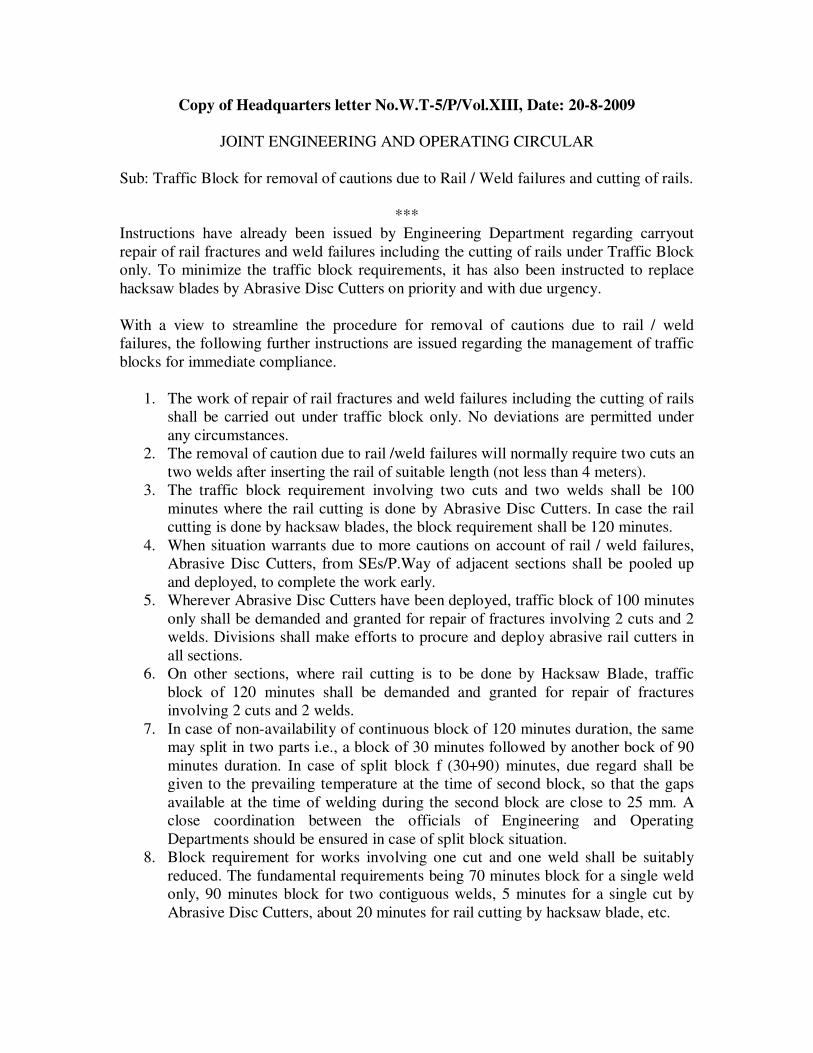
Copy of Headquarters letter No.W.T-5/P/Vol.XIII, Date: 20-8-2009
JOINT ENGINEERING AND OPERATING CIRCULAR
Sub: Traffic Block for removal of cautions due to Rail / Weld failures and cutting of rails.
***
Instructions have already been issued by Engineering Department regarding carryout
repair of rail fractures and weld failures including the cutting of rails under Traffic Block
only. To minimize the traffic block requirements, it has also been instructed to replace
hacksaw blades by Abrasive Disc Cutters on priority and with due urgency.
With a view to streamline the procedure for removal of cautions due to rail / weld
failures, the following further instructions are issued regarding the management of traffic
blocks for immediate compliance.
1. The work of repair of rail fractures and weld failures including the cutting of rails
shall be carried out under traffic block only. No deviations are permitted under
any circumstances.
2. The removal of caution due to rail /weld failures will normally require two cuts an
two welds after inserting the rail of suitable length (not less than 4 meters).
3. The traffic block requirement involving two cuts and two welds shall be 100
minutes where the rail cutting is done by Abrasive Disc Cutters. In case the rail
cutting is done by hacksaw blades, the block requirement shall be 120 minutes.
4. When situation warrants due to more cautions on account of rail / weld failures,
Abrasive Disc Cutters, from SEs/P.Way of adjacent sections shall be pooled up
and deployed, to complete the work early.
5. Wherever Abrasive Disc Cutters have been deployed, traffic block of 100 minutes
only shall be demanded and granted for repair of fractures involving 2 cuts and 2
welds. Divisions shall make efforts to procure and deploy abrasive rail cutters in
all sections.
6. On other sections, where rail cutting is to be done by Hacksaw Blade, traffic
block of 120 minutes shall be demanded and granted for repair of fractures
involving 2 cuts and 2 welds.
7. In case of non-availability of continuous block of 120 minutes duration, the same
may split in two parts i.e., a block of 30 minutes followed by another bock of 90
minutes duration. In case of split block f (30+90) minutes, due regard shall be
given to the prevailing temperature at the time of second block, so that the gaps
available at the time of welding during the second block are close to 25 mm. A
close coordination between the officials of Engineering and Operating
Departments should be ensured in case of split block situation.
8. Block requirement for works involving one cut and one weld shall be suitably
reduced. The fundamental requirements being 70 minutes block for a single weld
only, 90 minutes block for two contiguous welds, 5 minutes for a single cut by
Abrasive Disc Cutters, about 20 minutes for rail cutting by hacksaw blade, etc.

9. There instructions should be quickly percolated to all the officers and inspectors
of Operating and Engineering Departments in control offices as well as in the
field.
Sd/- (Rakesh Saksena) Sd/- (Pradeep Kumar)
Chief Operating Manager Principal Chief Engineer.

Copy of Headquarters lr. No.W.T-5/P/Vol.XIII, dated 20.8.2009 addressed to All
Sr.DEN/Co-ordinations of S.C.Railway
Sub: Repairs to rail / weld failures and cutting of rails on running lines.
***
Instructions exist vide para -15.08, Chapter XV of G&SR-2008 and also Rly. Board lr.
No.98/CE-II/INSPN.5 dt.7/15.8.98 that track works leading to discontinuity in track such
as causal renewal of rails, temporary / permanent repairs of rail /weld failures shall be
undertaken under traffic block only. It has come to notice that the work of rail cutting
prior to rail renewal is being undertaken in between the train gaps with banner flag and
caution order protection without ensuring traffic block, which is an unsafe practice. At
times, such situations have resulted into derailments also. It is pointed out that the work
of cutting of rails is an integral part of rail renewal activity and is therefore required to be
executed under clear block protection.
To avoid such unsafe situation, following instructions are issued on the subject matter for
strict compliance in the field with immediate effect.
1. Cutting of running rail on running lines should be undertaken under Traffic
Block only. No deviations are permitted under any circumstances.
2. The work of repair of rail fractures and weld failures including the cutting of
running rail shall be carried out under traffic block only.
3. To minimize the traffic block requirements, for works involving rail cutting,
hacksaw blades are replaced by the Abrasive Disc Cutters, on priority and
with due urgency.
4. Gas cutting shall not be carried out on running rails. In case it is essential to
resort to gas cutting due to emergency, the gas cut rail shall be treated as IMR
rail and same will be removed within 24 hours at first opportunity. Till such
time necessary speed restriction shall be imposed duly posting a watchman.
5. In case of rail cutting by Abrasive Disc Cutters, traffic block of 100 minutes
shall be demanded for repair of fractures involving 2 cuts and 2 welds.
6. In case of rail cutting by Hacksaw Blades, traffic block of 120 minutes shall
be demanded for repair of fractures involving 2 cuts and 2 welds.
7. In case of non-availability of continuous block of 120 minutes duration, the
same may be split in two parts, a block of 30 minutes for cutting followed by
another block of 90 minutes duration for welding.
8. Block requirement for works involving one cut and one weld shall be suitably
reduced.
This issues with the approval of PCE.
Sd/- (S.P.SAHU)
Chief Track Engineer

South Central Railway
Engineering Standing Order No.59
.
Sub: Anti-corrosive treatment of Rails, Welds and other P.Way fittings – Reg.
***
1. The problem of corrosion and formation of pits at liner contact area on rails exists in
some of the sections of this Railway. Identification of such sections was done and
circulated to Divisions for taking various preventive measures. The matter of
corrosion and its damaging effects had come up for serious discussions during the
Sr.DEN’s meeting held on 13.12.07. During the above meeting it was brought out
that heavy corrosion is also developing in some of the areas which are not identified
earlier. Taking above situation into account, the position has been reviewed and the
list of corrosion prone sections, division wise is revised as under:
S.No. Division Location
1. Vijayawada All routes of Vijayawada Division
2. Guntur KCC-GNT, GNT-TEL-RAL, GNT-
NLPD-NDKD-MRGA, GNT-NRT,
NDKD-MCLA
3. Secunderabd MDR-KI (UP& DN), PGDP-SC-
HYB-LPI (UP&DN)
4. Guntakal GDR-KHT-RU (UP & DN), RU-
TPTY (UP&DN_
5. Nanded Nil
6. All Passenger Platform lines at
stations of all divisions
--
8. All Tunnels of all Divisions
9. All cuttings in approaches of
Major towns of all Divisions.
2. It was further noted that the instructions on various measures to prevent corrosion are
not available in one single circular. Thus, a need to issue all related instructions in a
consolidated circular was felt. Therefore, various measures to control corrosion on
rails and fitting have been summarized as under:
2.1 Anti-corrosive treatment of rails, welds and other P.Way Fittings
(A) Frequency of lubrication of ERCs and sealing for liner contact area shall be as
under:
i. On corrosion prone areas ERC greasing (all 4 ERCs) and sealing of liner
contact area (only inside) – Once in a year
ii. On other areas ERC greasing (all 4 ERCs) – Once in 2 years
(B) In addition to the above, on identified corrosion prone areas painting of new rails
and in service rails shall be adopted as under:

a) Painting of new rails: All new rails shall be painted before laying, with one
prime coat of red lead and two coats of red oxide as per instructions circulated
vide letter No.W.501/1/7/Vol.VII, dated 8.4.04
b) Painting of in-service rails: Painting of in-service rails shall be carried out
depending upon condition, but not earlier than once in two years on inner
gauge face (web and flange) using two coats for anti-corrosive Bituminous
black paint as per instructions circulated vide lr. No.W.501/1/7/Vol.VII,
dt.8.4.2004. Sealing of liner contact area should be done after scrapping and
painting. The activities should be planned accordingly.
(C) Weld collar painting: On identified corrosion prone areas, weld collars shall be
painted once a year, with two coats of anti-corrosive bituminous black paint
conforming to IS 9862-1981, to a thickness of 200 Microns and on non-corrosive
prone areas, once in two years.
(D) Use of galvanized metal liners, galvanized plate screws and stretcher bars in
points and crossing areas.
a) Galvanized liners – In all identified corrosion prone areas.
b) Galvanized Plate screws and Stretcher bars - In all areas irrespective of
corrosion Proneness.
(E) Frequency of lubrication of plate screws in points and crossings-
i) In corrosion prone areas - Once in a year
ii) In other areas - Once in two years
This issued with the approval of PCE.
Sd/- (S.P.SAHU)
Chief Track Engineer
Forwarded vide lr. No.501/I/7/Vol.VIII Dt.02.1.08

Copy of Headquarters lr. No.W.413/GENL/RWF/XXIV, dated15.6.2009 addressed
to Sr.DEN/Co-ordinations of S.C.Railway
Sub: Rail / Weld failures – Dent / Notch marks.
***
Recently one Rail fracture had taken place at km.211/30-32 Dn. line between
BTTR-SVPM and GDR-BZA section on 8.6.2009. This was reported as Weld failure.
On examination of the broken pieces, a deep Dent Mark was noticed on the rail
foot close to the SKV weld which was the origin for causing the Rail fracture.
2. On earlier occasion also one more Rail breakage had taken place on 5.12.2008 at
km.251/5-3 up line between MCI-MMZ of KZJ-BPQ section for which the cause of
failure was also due to dent / cut mark at rail foot.
Such type of Dent/Notch marks on UTS rails are serious cause of concerned
resulting into Rail fracture. Such Dent/cuts are caused due to mishandling of rails during
unloading or laying.
3. In order to avoid such unsafe situations, it is advised to carryout thorough
inspection of rails in the section and take action to identify and attend such locations.
Sr.DEN/DEN of the section should be advised to take this matter seriously and take
necessary remedial action. Simultaneously, staff at all levels need to be counseling
regarding proper handling of rails.
Action taken in this regard may be advised to undersigned.
Sd/- (S.P.SAHU)
Chief Track Engineer

Copy of Headquarters letter No.509/P/AT Welders & Welding, dated 29.10.2008
addressed to All Sr.DEN/Co-ordinations of S.C.Railway.
Sub: Standard Register for recording rail / weld fractures – reg.
Ref: CTE’s Inspection Notes No.35/2008 vide letter No.W.246/CTE/04/Vol.III,
dt.20.10.08.
***
A standard printed register for recording rail / weld fractures (for use of
SSE/SE/P.Way of open line) containing 15 columns for recording various details was
issued to Division earlier.
CTE vide Para-7 of the above referred Inspection Notes has observed that the
Register do not have columns for noting down the name of agency, name of welder etc.,
which are required to monitor performance of the same. It was advised to re-design the
proforma of the register incorporating these details. Divisions are advised to furnish the
desired revised format and the number of copies required for each division, to arrange
from Hqrs.
In the meanwhile, the details of welding agency and the name of welder may
please be recorded in the Column No.11 (type of welder) and Column No.12 (date of
welding) along with the details for the printed item in the next line.
Please acknowledge the receipt of this letter, with the details asked above.
Sd/- (J.N.GUPTA)
Dy.CE/Tr.II

Copy of lr.No.B/W.413/GL/Joggled Fish Plates/P.Way-II, dated 14.11.07 addressed
to All ADENs & SSEs/SEs/P.Way on BZA Division.
Sub: Precautions to be taken on Passenger intensive routes – Joggling of AT
Welds – Reg.
Ref: 1) CTE/SCs letter Nos. W.413/Joggling, dt.21.6.07, 10.8.07 and 13.9.7
2) This office letters of even No., dated 8.7.07 and20.9.07.
***
Please refer to the letters cited under reference wherein it was advised that
joggling of AT welds has to be done at the following locations as per the extent
instructions and the same should be completed before 31.10.2007 without fail.
1) All AT welds in locations where the track has carried more than 50% of the
stipulated GMT.
2) All AT welds in well fracture prone locations.
3) All AT welds on the outer rails of curves with curvature ½0 and above.
4) All AT welds on major and important bridges and their approaches on either side
upto 100 Mtrs.
5) All AT welds on Track where the height of the bank is 4 M and above.
Please ensure Joggled fish plating of all the AT welds in the above locations of
your section is completed before 24.11.07 without fail and the compliance report should
be submitted to this office to advise Hqrs. Office by 26.11.07.
This has the approval of Sr.DEN/Co-ord/BZA.
Sd/-
For Sr.DEN/Co-ord/BZA
Copy to: All DENs of BZA Division.
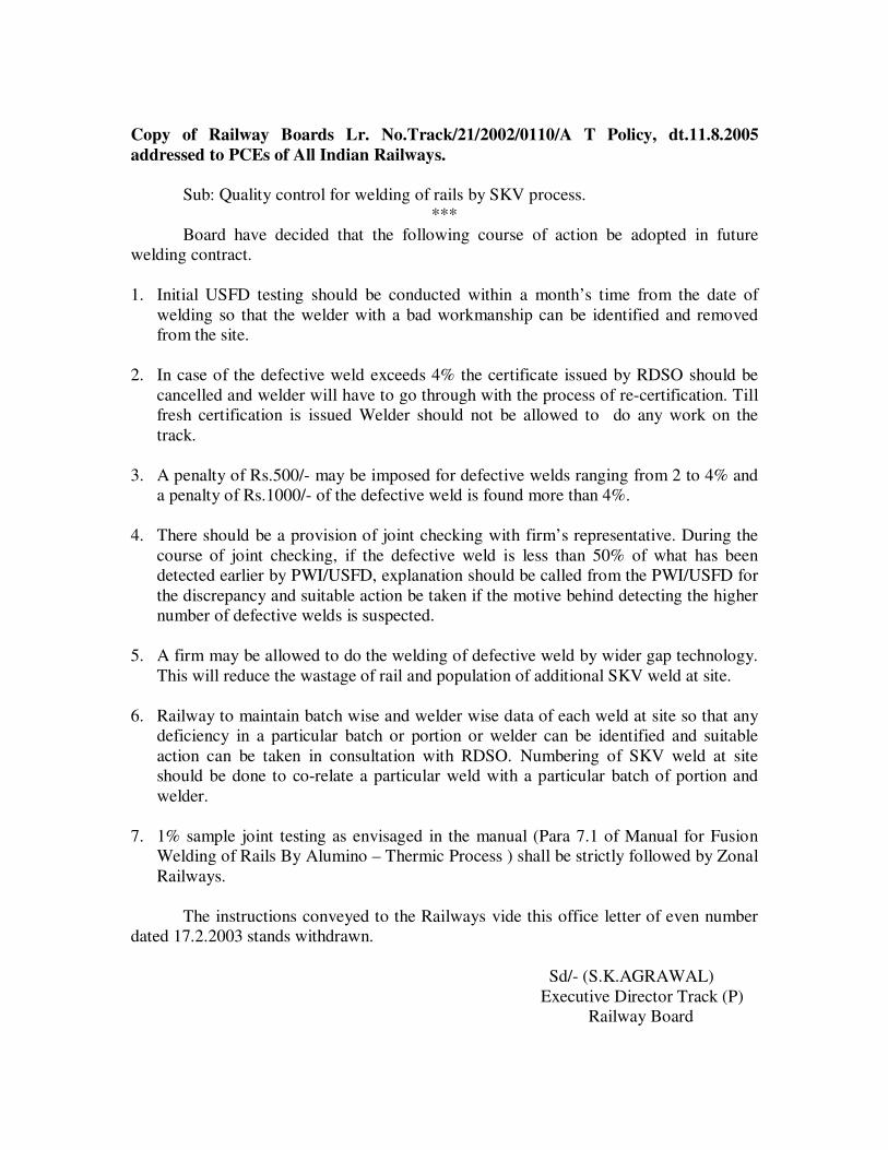
Copy of Railway Boards Lr. No.Track/21/2002/0110/A T Policy, dt.11.8.2005
addressed to PCEs of All Indian Railways.
Sub: Quality control for welding of rails by SKV process.
***
Board have decided that the following course of action be adopted in future
welding contract.
1. Initial USFD testing should be conducted within a month’s time from the date of
welding so that the welder with a bad workmanship can be identified and removed
from the site.
2. In case of the defective weld exceeds 4% the certificate issued by RDSO should be
cancelled and welder will have to go through with the process of re-certification. Till
fresh certification is issued Welder should not be allowed to do any work on the
track.
3. A penalty of Rs.500/- may be imposed for defective welds ranging from 2 to 4% and
a penalty of Rs.1000/- of the defective weld is found more than 4%.
4. There should be a provision of joint checking with firm’s representative. During the
course of joint checking, if the defective weld is less than 50% of what has been
detected earlier by PWI/USFD, explanation should be called from the PWI/USFD for
the discrepancy and suitable action be taken if the motive behind detecting the higher
number of defective welds is suspected.
5. A firm may be allowed to do the welding of defective weld by wider gap technology.
This will reduce the wastage of rail and population of additional SKV weld at site.
6. Railway to maintain batch wise and welder wise data of each weld at site so that any
deficiency in a particular batch or portion or welder can be identified and suitable
action can be taken in consultation with RDSO. Numbering of SKV weld at site
should be done to co-relate a particular weld with a particular batch of portion and
welder.
7. 1% sample joint testing as envisaged in the manual (Para 7.1 of Manual for Fusion
Welding of Rails By Alumino – Thermic Process ) shall be strictly followed by Zonal
Railways.
The instructions conveyed to the Railways vide this office letter of even number
dated 17.2.2003 stands withdrawn.
Sd/- (S.K.AGRAWAL)
Executive Director Track (P)
Railway Board

Copy of Headquarters letter No.W.509/P/W-6/Vol.XI, dt.27.12.07 addressed to All
Sr.DEN/Co-ordinations of S.C.Railway.
Sub: Storage of welding portions and other materials related to rail welding.
Ref: Correction slip No.7, dt.7.12.07 to Allumino Thiermit (AT) Welding Manual
circulated vide Hqrs. lr. No.W.509/W-6/Vol.XI, dt.26.12.07.
***
The above mentioned Correction Slip stipulates detailed instructions on careful
storage and handing of AT welding portions.
During inspections, it is noted that the present practice of storage and handling of
welding portions and related materials requires improvement and there is a need to
tighten up the machinery.
As per the C.S., there has to be a separately earmarked room for storing of
welding portions with proper system of storing and handling.
Sr.DEN/Co-ord are requested to plan for developing such specially earmarked
room at each PWI HQ to ensure that welding portions are stored / handled as per the
instructions contained in the above mentioned Correction Slip. This will be another step
in the direction of improvement of welding quality.
An action plan for developing the facility should be submitted to the undersigned
by 15.1.2008.
Please acknowledge receipt.
Sd/- (S.P.SAHU)
Chief Track Engineer

Copy of Headquarters letter No.W.32/1/NG/PWIS/Thermit Welding, dt.18.5.07
addressed to All Sr.DEN/Co-ordinations of S.C.Railway.
Sub: Competency Certificates of Welders.
***
Cases have come to notice that Competency Certificate of agencies’ Welders
carrying out the welding are not found to be available with the Railways for immediate
verification. In some of the cases, long time has been taken to produce competency
certificate when called for verification.
Henceforth, it shall be ensured that Welders’ Competency Certificates (Original)
shall be kept in the custody of sectional ADEN till such time Welder is working in his
session. Welder shall carry attested Xerox copy of Competency Certificate for
verification by inspecting Officers.
List indicating name of welder and Identification Code should be available in
Divisional Engineering control for cross-check and verification. A list of agencies’
welders working in the division along with competency certificate number and
identification code should be sent to Hqrs. for record by 25.5.2007.
Sd/- (S.P.SAHU)
Chief Track Engineer

Copy of Headquarters letter No.W.496/TWR/W-6, dt.11.4.07 addressed to All
Sr.DEN/Co-ordinations of S.C.Railway.
Sub: Precautions of Consumables / Accessories required for Departmental
Welding
***
It has come to notice that some of the consumables / accessories required for
departmental welding are not available in sufficient quantities affecting quality of
welding work. The value of these items is very negligible as compared to the overall cost
of welding. However, considering the quality aspects, it is essential that these items are
procured locally whenever required preferably through the petrol imprest available with
AENs for welding work. This will avoid creating of inventory and wastage due to long
storage period. The amount of imprest may be got enhanced considering the monthly
requirement and the imprest may be designated as “Petrol-cum-Consumable Imprest
for Welding”. A copy of the statement obtained from BZA Division is enclosed for
ready reference. This statement indicates consumables / accessories, which are generally
found inadequate.
It is advised to take necessary action to suitably enhance the amount of imprest and issue
instructions to AENs for arranging procurement of consumables / accessories from the
approved RDSO suppliers as and when required.
Sd/- (S.P.SAHU)
Chief Track Engineer

Copy of Railway Board’s letter No.Track/21/2004/0902/7, dated 08.02.08 addressed
to PCEs of All Indian Railways.
Sub: USFD testing of AT welds using digital AT weld testers.
***
Digital Ultrasonic equipment for Aluminothermic Weld was developed by RDSO
in association with trade for quite some time. These Ultrasonic Weld Testers are not only
handy but also can record data being a digital equipment. Moreover, PWI/USFD can
himself do the probing operation and view the signals on the monitor simultaneously.
Therefore, the quality of testing improves drastically with its use.
As on date, there are two RDSO approved vendors for the equipment, namely
M/s.Modsonics Instrument Manufacturing Company Pvt., Ltd., Ahemdabad and M/s.
Parikh Industries, Mumbai.
Railway Board has now decided that al ultrasonic testing of AT welds henceforth
would be carried out using RDSO approved digital ultrasonic equipment. Six months
time period has been fixed for the procurement of equipment / development of requisite
infrastructure. Therefore, Railways are advised to take necessary action in this regard and
compliance report be sent to Board.
Sd/- (S.K.AGRAWAL)
Executive Director Track (P)
Railway Board.

Copy of Headquarters letter No.W.507/Genl/USFD/Vol.XX/2, dated 04.03.2008
addressed to Sr.DEN/Co-ordinations of S.C. Railway.
Sub: USFD testing of AT welds using digital AT weld testers.
Ref: Rly. Board lr. No.Track/21/2004/0902/7, dt.8.2.08.
***
Railway Board vide letter under reference, advised that all ultrasonic testing of
AT welds henceforth would be carried out using RDSO approved Digital Ultrasonic
equipment. Six months time period has been fixed for the procurement of equipment /
development of requisite infrastructure.
In view of the above, divisions are advised to make necessary arrangements for
procurement of the above mentioned machine based on the requirement. The necessary
RDSO specification, along with Budgetary offer received from he M/s.Electronic &
Engineering Co.(I) P. Ltd., is enclosed herewith for immediate process.
Sr.DEN/Co-ord are personally responsible for submission of the vetted indent as
per the requirement, to this office by 20.3.2008.
This is as per instruction of CTE please.
Encl: As above
Sd/- (B.VENKATA RAO)
XEN/TRACK-1
For Chief Track Engineer.

Copy of Headquarters letter No.W.509/P/Vol.XI, dt.25.07.2007 addressed to All
Sr.DEN/Co-ordinations of S.C.Railway.
Sub: Improvement in Welding Technology.
Ref: ED/Tr/RDSO’s lr. No.CT/Welding/Policy, dt.21.6.07
***
RDSO vide above referred letter (copy enclosed) have advised six welding firms
to gear up for improving the welding technology by:
i) Introduction of Compressed Air Pre-heating along with use of 3 piece
Moulds w.e.f 01.09.2007
ii) Use of Automatic Tapping Thimbles w.e.f. 01.12.2007
It is stated that the above deadline has been fixed by the Railway Board.
Divisions are therefore, advised to immediately follow the condition as mentioned
at (i) above, i.e, use of Compressed Air Pre-heating arrangement along with 3-piece
moulds for All AT welding tenders in which execution will come into effect from
1.9.07 onwards. These instructions should be specifically noted and implemented in the
interest of improvement of AT welding quality immediately.
Please acknowledge receipt of the letter.
Sd/- (S.P.SAHU)
Chief Track Engineer

Copy of Railway Board’s letter No.Track/21/99/0910/7, dated 30.5.07 addressed to
PCEs of All Indian Railways.
Sub: Precautions to be taken on Passenger intensive routes.
***
Board (ME) desired that following precautions should be taken on the passenger
intensive routes (Prority-1) and on CC+8+2T routes (Priority-2):
1. Joggle fish plating of the thermit welds (irrespective of age) on the outer rail of the
curves should be done on priority. The fist plating should be done using clamps
without drilling of holes.
2. Joggle fish plating of the thermit weld on the bridges along with its approaches upto
100 m should be done.
3. Each and every weld fracture is to be analyzed by sectional Sr.DEN/DEN. It should
be ascertained whether weld failure is sudden, due to some impact or it is due to an
inherent defect leading to fatigue like, improper fusion or blow holes or presence of
fin etc., remedial action due to be identified and taken promptly.
Sd/- (S.K.AGRAWAL)
Executive Director Track (P)
Railway Board.

Copy of Headquarters letter No.413/Joggling, dt._______ addressed to All
Sr.DEN/Co-ordinations of S.C.Railway.
Sub: Joggled fish plating of all thermit wells on sections with traffic density
less than 15 GMT.
***
As per Railway Board E.S.O. No.34/3/1 (Revision-1) dated 10.11.2004 para 5(1)
for lines with traffic density less than 15 GMT normally TWR is to be planned on
completion of 50% stipulated fatigue life of the rail. If it is decided to continue with old
thermit welds in view of very less traffic, complete weld testing be done, once in five
years, irrespective whether testing is due as per GMT criteria or not. In case such testing
is not done, welds more than 15 years old should be joggled fish plated with two far end
tight bolts”.
In this context due to the constraint in manpower for USFD testing, it is decided
to joggle fishplate all thermit welds of age 15 years or more where traffic density is less
than 15 GMT. Hence, it is advised to plan for the joggle fish plating of all such thermit
welds on identical locations in following sections.
Division Section
Secunderabad SC-WD (DN LINE)
MTMI-JPTN
VKB-PRLI
SNF-MLY (Bye Pass)
DKJ-MUGR
KRA-SYI
Nanded MMR-PAU
PBN-PRLI
ADB-PMPT
Hyderabad FM-DHNE
Guntur NLPD-NDKD-MRGA
Divisions are advise to identify the number of welds requiring fish plating in
above mentioned sections and plan for fish plating duly making necessary arrangements
for procuring fish plates. Till such time fish plating is not done, weld testing may be
carried out as per prescribed frequency.
Sd/- (S.P.SAHU)
Chief Track Engineer

Copy of Headquarters letter No.W.413/Joggling, dt.21.6.07 addressed to All
Sr.DEN/Co-ordinations of S.C.Railway.
Sub: Precautions to be taken on Passenger intensive routes.
***
In regard to the above subject, a copy of the Railway Board’s letter
No.Track/21/99/0910/7, dt.30.5.2007 is enclosed herewith for information, wherein it has
been instructed to take the followed precautions on the passenger intensity routes
(priority-1) and on CC+8+2T routes (Priority-2).
1. Joggle fish plating of the thermit welds (irrespective of age) on the outer rail
of the curves should be done on priority. The fish plating should be done
using clamps without drilling of holes.
2. Joggle fish plating of the thermit weld on the bridges along with its
approaches upto 100 m should be done.
3. Each and every weld fracture is to be analysed by sectional Sr.DEN/DEN. It
should be ascertained whether weld failure defect leading to fatigue like,
improper fusion or blow holes or presence of fin etc., remedial action due to
be identified and taken promptly.
In this connection it is advised to follow Board’s instructions as received giving
priority to sharp curves (In order of sharpness in the division) and taking into account the
importance of routes based on passenger traffic.
The progress of the above work done should be furnished in the new PCDO
proforma every month without fail so as to enable this office to compile and put up to
Board.
Sd/- (S.P.SAHU)
Chief Track Engineer

ENGINEERING STANDING ORDER NO..60
Sub:-Corrosion on Rail foot due to Liner Bite - Protection – reg.
*****
Instructions regarding protection of rail against corrosion on rail due to liner bite
have been issued from time to time. On study of the problem in detail, it is noted that average
rate of corrosion on rail foot is of the order of approx. 1 mm per year without application of
any protective measures. In order to overcome the problem, detailed consolidated instructions
on anti-corrosive treatment or rails, welds and other P.Way fittings have also been issued vide
ESO No.59, indicting various protective measures to be taken on rails and other fittings.
Divisions should ;meticulously adopt all the measures mentioned therein.
2. It is noted that the ate of corrosion has slowed down after taking preventive measures,
like; initial painting of rails, sealing of liner contact area with grease graphite, galvanizing of
liners etc. Study of rails laid in severely affected corrosion prone areas in BZA Divn. Revealed
that even with protection measures, like initial panting of rails and sealing of liner contact area
at one year interval, there is possibility of corrosion at liner contact area setting-in after a
period of 3 to 4 years. Considering the situation as brought out above, there is likelihood of
corrosion pit crossing a limit of 1 mm within a period of 4 to 5 years. It has also been noted
that there is very little corrosion either on rail foot or, fittings on non-gauge face side. Also, the
area in between the sleepers is comparatively free of corrosion pits.
3. In order to overcome the problem of rail failures, rising out of deep corrosion pits in liner
contact area, it has been decided to carryout he operation of rail distressing involving shifting
of liner contact area irrespective of any other criteria. During this process,. It shall be ensured
that the exiting liner contact area is shifted away from the sleeper set by a minimum of 150mm
by physically pulling the rail, using rollers and rail dollies / tensors, in the direction of Traffic
in case of Double line, followed by distressing of panels using rail tensor, whenever required.
This operation shall be addition to the corrosion protection measures as stipulated in ESO
No.59.During this process, renewal of worn-out / crushed rubber pads, corrode ERCs and
liners shall also be carried out.
4. Accordingly, the operation of shifting liner contact area and distressing, on corrosion
prone areas shall be carried out a under
a. At an interval of 5 years, or, before corrosion pit depth at liner contact area reaches a
limit of 1.5mm, which ever is earlier.
b. Next round of de-stressing shall again be carried out after next 5 years, or, before
corrosion pit depth at liner contact area reaches a limit of 1.5mm at shifted location,
whichever is earlier.
c. During each process of de-stressing, it should be ensured that liner contact area
is shifted away from the existing rail sea in the direction of traffic in case of
Double line, by a minimum of 15mm, so that corrosion pit, if any formed at
sleeper seat gets shifted away and does not aggravate further. In any case,

efforts should be made to ensure that corrosion at liner contact area is not
allowed to exceed a limit of 1.5mm t any point of time.
d. The above operation shall be repeated at interval mentioned at (i) & (ii) above,
till rail achieves full GMT, or, there is no possibility of further shifting of rails
due to existence of number of pits on rail foot.
e. When the stage stated at (iii) above ha reached, and if rail still has residual life,
operation of rail interchanging (left to right and vice-versa) shall be tried, so that
corrosion pits are shifted to non-gauge face side.
f. The operation of sealing of liner contact area and other corrosion protection
measures shall continue to be carried out as per ESO No. 59 dt.02.10.08.
g. During the process of de-stressing an shifting of liner contact area, renewal of
wornout / crushed rubber pads and corroded ERCs & Liners shall also be
carried out.
h. Destressing warranted on any other account as stipulated in LWR Manual vide
Para No.6.4.1 shall be carried out as per the site requirement.
5. Keeping in view corrosion of rail on both gauge face and non-gauge face at platform
lines of station yards para 2.1 (b)(b) of ESO No.59 stands modified as under :
“In-service painting of rails: In-service painting of rails shall be carried out
depending upon condition, but not earlier than one in two years. Area to be covered
shall be web and top flange only.
For locations other than platform lines, only gauge face side shall be painted. For
platform lines of station yards, Non gauge face side will also be painted.
Such painting shall consist of two coats of anti-corrosive Bituminous black paint
conforming to IS 9862-1981 to a thickness of 100 microns, as per instructions
circulated vide Lr. No.W.501/1/7/Vol.V, dt.8.4.04.
Sealing of liner contact area should b done after scrapping and painting. The activities
should be planned accordingly.”
6.1 Corrosion Measurement and recording: At present there is no system of
measuring and monitoring the problem of corrosion on rail foot. In order to know and
monitor extent of corrosion on rail foot, particularly at liner contact area, periodical
measurement of corrosion pit bother vertically and laterally (reduction in bottom flange
width of rail), shall be taken using straight edge and filler gauges. Such measurements
shall be recorded at a frequency of one year on every 100 sleepers by removing ERCs &
liners on gauge face side. Results of such measurement shall be recorded in a register
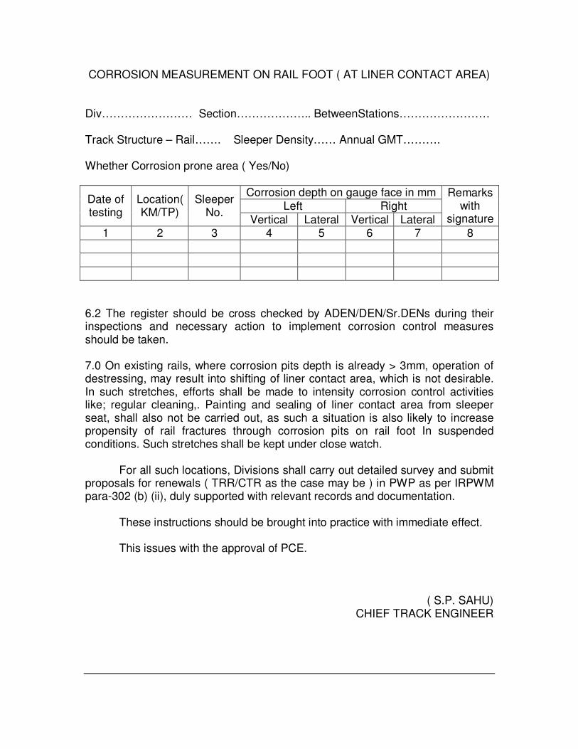
CORROSION MEASUREMENT ON RAIL FOOT ( AT LINER CONTACT AREA)
Div…………………… Section……………….. BetweenStations…………………… Track Structure – Rail……. Sleeper Density…… Annual GMT………. Whether Corrosion prone area ( Yes/No)
Corrosion depth on gauge face in mm Left Right
Date of testing
Location( KM/TP)
Sleeper No.
Vertical Lateral Vertical Lateral
Remarks with
signature
1 2 3 4 5 6 7 8 6.2 The register should be cross checked by ADEN/DEN/Sr.DENs during their inspections and necessary action to implement corrosion control measures should be taken. 7.0 On existing rails, where corrosion pits depth is already > 3mm, operation of destressing, may result into shifting of liner contact area, which is not desirable. In such stretches, efforts shall be made to intensity corrosion control activities like; regular cleaning,. Painting and sealing of liner contact area from sleeper seat, shall also not be carried out, as such a situation is also likely to increase propensity of rail fractures through corrosion pits on rail foot In suspended conditions. Such stretches shall be kept under close watch. For all such locations, Divisions shall carry out detailed survey and submit proposals for renewals ( TRR/CTR as the case may be ) in PWP as per IRPWM para-302 (b) (ii), duly supported with relevant records and documentation. These instructions should be brought into practice with immediate effect. This issues with the approval of PCE.
( S.P. SAHU) CHIEF TRACK ENGINEER

South Central Railway
Office of the
DRM/Works/SC
No.CW.506.Tra ck/Grade/Genl. Date 25.5.2007
All ADENs / SC Division
Sub: Performance of SKV Welders and Grading.
***
A database has been developed at the Divisional office and Headquarters. CTE
has given instructions to assess the performance of the welders an grading should be
given to each welder working in your section. As ` ‘A’,’B’ or ‘C’. The welders whose
grade is ‘A & B’ only should be utilize in the field as welders. The other welders who are
graded as ‘C’ should be utilized for supporting the welder and after they gain confidence,
they are supposed to be upgraded. However, no welding should be done in the field who
are not having valid compe6tency certificate and graded as ‘B’ or ‘C’.
Sample proforma is enclosed to fallow and the details available are to be update
and submitted to the undersigned along with the number of weldings done by the
individual during the year 2006 till date. Their performance results in terms of defective
joints / failed joints shall b shown and considered for awarding gradations. The guidelines
given may be follows.
Marks to be awarded:
• For Technical knowledge - 35 Marks
• For Skill in execution. - 35 Marks
• For quality welding - 30 Marks
(Based on defective/failed joints)
-------
Total 100 Marks
-----
Grading
A > or= 90 Marks
B < 90 and > or = 75 Marks
C < 75 Marks

CORRECTION SLIP NO.1 ENGINEERING STANDING ORDER NO.3 of 01.2.1999
Sub:-Guidelines for containing rail fractures/weld failures.
****
In partial modification to the above Standing order, the following amendments are
made to the para mentioned below:-
Existing para No.2.1. shall be read as under:=
Thermit welding should preferably be done on cess. When the welding work is done on
the cess full rail length should be leveled by supporting on at least ten wooden blocks on
either side, if done in site, it should be done under line block of adequate duration. The
rail fastenings for at least five sleepers on either side of the proposed weld shall be
loosened to avoid internal contraction stress at the joint during cooling. The approximate
time required for various operation for execution of SKV welding in situ under traffic
block are indicated below:-
Sl.
No
Process involved 52 Kg Section
Welding Time
60 Kg Section
Welding Time
1. Loosening of rail fastenings, gap
creation, alignment and Rail end
cleaning.
15-20 minutes 15-20 minutes
2. Burner Stand setting, crucible stand
setting ,mould fixing & luting
10 minutes 10 minutes
3. Pre-heating 10 minutes 12 minutes
4, Reaction time, removal of burner,
tapping and removal of crucible stand
3 minutes 3 minutes
5 Mould waiting time 5 minutes 6 minutes
6. Trimming of weld 3 minutes 3 minutes
7. First train passing time 30 minutes 30 minutes
8. TOTAL 76-81 MINUTES 79-84 MNUTES
Hence, f welding is done in situ, it should be done under line block of minimum 75
minutes for SKV welding process.
Sd/- (G.P. Mallikharjun)
Principal Chief Engineer

USFD Testing of
AT Welds

ULTRASONIC TESTING OF ALUMINO-THERMIC WELDED RAIL JOINTS
1. SCOPE: Following types of testing for Alumino Thermic welds have been
prescribed. These are:
(a) Testing of weld head/web, which gets covered during through
periodic rail testing by SRT/DRT. The frequency of testing in this
case is as per para 6.8.1.1 of USFD Manual. As per this testing
defects detected in weld heads are classified as IMRW and OBSW
aide Annexure II. The action to be taken for such defective welds is
as per para 6.4
(b) Periodic testing of complete weld by hand probing of weld
head/web and bottom flange using Oº 2MHz, 70º 2 MHz, 45º 2 MHz
probe ( AT weld foot scanning for half moon shaped defect) and 70º
2 MHz ( 8 x 8 mm) probes. The frequency of testing in this case is
as per 6.8.2.1 of USFD Manual. As per this testing defects detected
in welds are classified as “ DFW “. The action to be taken for such
defective welds is as per Para 6.6 of USFD manual.
(c) Besides this, welds are also tested after their execution using Oº 2
MHz, 70º 2 MHZ, 45º 2 MHz probe( AT weld foot scanning for
clustered defect/ micro porosities in web foot region) and 45º 2MHz
( Tandem probe scanning for lack of fusion). This test is termed as
Initial Acceptance Test. As per this testing, defects detected in
welds are classified as “ DFW “. The action to be taken for such
defective welds is as per Para 8.10 of USFD manual.
2. Equipment : Any RDSO approved model of ultrasonic equipment for
Alumino-thermic welded rail joints as per RDSO specification No.
M&C/NDT/129/2005 or its latest version along with rig for tandem testing.

3. Probes :
( i) Normal/Oº , 2 MHz, 18 mm Dia, Double crystal - 1 no.
( ii ) 45º, 2 MHz, 20 mm Dia. Or 20mmx 20 mm square crystal size, Single
crystal - 3 nos
( iii ) 70º, 2 MHz, 20 mm Dia. Or 20mmx 20 mm square crystal size,
Single crystal - 1 no.
( iv) 70º, 2 MHz, 8 mm x 8 mm crystal size, Single crystal - 1 no
4. Cable : Co-axial cable for each probe shall be used. The length shall not
be more than 2 mtrs.
5. Couplant : Soft grease shall be used as couplant.
6. Testing procedure and Classification:
Sl. No.
Probe Calibration
Sensitivity Defect Classification(DFW)
Type of defect Detected
Location
1 Oº 2 MHz
300 mm
60% FSH on 3 mm Ø hole in head
From head 40% or more ht.From web or foot >20% ht
To detect Porosity, Blow holes, Slag inclusion in Head&upto mid web of weld
Head & Web
2 70º S/C 2MHZ
300 mm
60% FSH on 3 mm Ø hole in head
From head 40% or more ht
To detect lack of Fusion, Porosity, Blow holes, Slag inclusion, Crack in Head of AT weld
Head
3 70º S/C 2MHZ
300 mm
60% FSH on 3 mm Ø hole in the middle of the Flange of AT weld
40% or more ht
To detect lack of fusion, Porosity, Blow holes, Slag inclusion in Flange of AT weld
Foot
4 45º S/C 2 MHZ
500 mm
60% FSH on Simulated notch at Bottom of AT weld
20% or more ht
To detect Half-moon shaped defect ay bottom of weld
Foot
5
70º S/C 2 MHZ ( 8x8
300mm
60% FSH on Simulated
20% or more ht
To detect Half-moon shaped defect ay bottom
Foot

mm) notch at Bottom of AT weld
of weld
6 45º/45º S/C 2 MHZ (Tandem Technique)
500 mm
100% of FSH and increase the Gain by 10db
40% or more To detect vertical oriented defects such as lack of fusion in rail head, web and foot region below web.
Head, Web & foot below web
7. Defect Classification, marking and action taken:
Classification
Marking on both sides of web
Action to be taken
DFW + + With red paint
For NEW Welds: These DFW welds shall be cropped, re-welded and tested again. For Service welds: These DEW welds on detection, SE/USFD/shall impose SR 30kmph or stricter immediately. He should communicate to Sec Se about the flaw location who shall ensure the following: ( i ) protection of DFW weld by jog. Fps using min.2 tight clamps/2 far end tight bolts one on each side, after which SR can be relaxed upto 100/75 Kmph for Goods/Pass trains. ( ii ) In case protection of DFW weld has been done using jog.FPs with clamps, the DFW weld shall be replaced with in 15 days. However, protection of DFW weld has a been done using jog.FPs with 2 far end tight bolts SR shall continue till weld is replaced which should not be later than 3 months. The DFW weld with SR may be continued in track if the track is to be renewed with in 12 months.

8. Weld Testing Frequency ( SKV )
S.No Type of Weld
Type of testing Testing Schedule
Acceptance Test Immediately after welding First Periodic Test One year
Routes Having GMT
Frequency
> 45 2 years > 30 < 45 3 years > 15 < 30 4 years
1 SKV
Further Tests based on route GMT
0 - 15 5 years
9. Note: ( i ) Due to unusual high weld failure or abnormal development in some sections, Chief Engineer may order testing of welds early, as per need. ( ii )The USFD testing can be dispensed with in case of those welds which are more than 15 years old and protected by joggled fish plates with far end tight bolts.
( iii ) TWR should be planned after the welds have carried 50% of the stipulated GMT of Rails.


Extracts from T-19
Manual – 1994

INDIAN RAILWAY STANDARD SPECIFICATION FOR FUSION WELDING OF RAILS BY ALUMINO – THERMIC PROCESS
Serial No. IRS T-19-1994 EXTRACTS
FOREWORD This specification is issued under the fixed serial No.T-19. This was originally adopted in 1961 and was revised in 1965 and 1984. This third revision is necessitated to include current technological improvements in the process. In this revised specification, test requirements of 90 UTS, 110 UTS and Head Hardened rails have been incorporated, acceptable percentage of porosity, tapping time and transverse breaking load requirements have been revised. 1. INTRODUCTION 1.1 The soundness of the welds produced by alumino - thermic process depends
on the quality of (a) alumino-thermic mixture hereinafter referred to as the ‘MIXTURE’ and (b) the technical control exercised during the preparation for and the execution of the welding by this process.
1.2. The quantity of the “MIXTURE” required for welding one rail joint shall be called a ‘portion’.
1.3. A batch shall consist of a number of “portions” manufactured from similarly
and simultaneously treated raw materials. 1.4. ‘Portions’ manufactured by agencies approved by RDSO and accepted by
nominated inspecting authority shall only be used. 1.5. Except for welds executed for laboratory evaluation and acceptance test, all
welds shall be executed under the supervision of personnel possessing valid competency certificate either from RDSO or from Thermit Portion Plant, Northern Railway, Charbagh, Lucknow.
1.6. No changes in weld design, range of weld metal chemistry, its acceptance
tests and the methods of welding shall be made without the consent of the approving authority. Approving Authority shall mean Director General, Research, Design & Standards Organization (Ministry of Railways), Manak Nagar, Lucknow � 226011 or his representative.
1.7 The numerical values may be rounded off as per IS:2. 2. SCOPE 2.1 This specification is for A.T. Welding of rails to IRS Specification T-12 and
UIC Specification 860-0, Alloy Steel Rails, viz., Chrome Manganese and Chrome-Vanadium and Head Hardened rails.
2.2 This Indian Railway Standard covers:-

a) Technical requirements for thermit portions and welded joints including various acceptance tests.
b) Procedure for approval of Alumino-thermic “portion manufacturers” c) Procedure for approval of A.T. Welding Supervisors, Welders and
contracting firms. d) Acceptance tests for in-situ and cess Alumino Thermic joints.
2.3 Reference Documents: This standard refers to the following Indian Standards of the Bureau of Indian Standards. These should be available at the manufacturers works for reference. (i) IS:2 Rules for rounding off numerical values (ii) IS:187 Cotton long cloth (iii) IS:9738 Polyethylene bags for general purposes (iv) IS:2500(Pt. I) Sampling inspection tables:
Part I inspection by attributes and by count of defects.
(v) IS:1500 Method for Brinnell hardness test for metallic materials.
PART A – Technical Requirements for Thermit Portions 3. SUPPLY OF THE “PORTIONS” 3.1 The portions shall be submitted for acceptance batch wise as per one of the
following two provisions:
a) A batch shall consist of 300 portions or part thereof manufacture on the same day from similarly and simultaneously treated raw materials.
b) For the manufacturers having ISO:9000 certification, a batch may consist of 600 portions or part thereof manufactured on the same day from similarly treated raw materials and processing and mixing of all ingredients being done completely under automation by four feeder channels. (The nature and category of complete automation) and process control will be certified by the inspecting authority for permitting such batch). However, if automatic working of any of the four feeder channels gets stopped, the batch size shall revert back to 300nos. Batch numbering shall be given year-wise in six digits code, whose first two digits will indicate two digits of the year of manufacture and the balance 4 digits, the serial number of the batch. The batch number at the beginning of each year shall, therefore, commence from 0001.
3.2 Every portion shall be packed in a moisture proof bag of Polyethylene to
IS:9738, ‘Indian Standard Specification for Polyethylene bags for general Purposes’ Grade HM HDPE of 150 micron thickness which should be sealed so as to make it airtight. The Polyethylene bag should then be packed in a heavy duty bag made of New cloth to IS:187. The open end of the cloth bag

shall be stitched and sealed in such a manner that there is no access to the ‘portion’ without damaging the bag or breaking its seal.
3.3 Following particulars shall be indicated on two similar labels - One placed inside the Polyethylene bag containing the portion and the other outside with the seal on the bag:- i) Batch No. ii) Portion No. iii) Date of manufacture iv) The section and grade of rail to be welded v) Welding technique vi) Insignia of the firm `The insignia of the firm and rail type should be printed on the exterior of the cloth bag as per the under-mentioned colour scheme:-
S.No. Rail type Colour 1. 72 UTS Red 2. 90 UTS Green 3. 110 UTS
(Chrome Manganese & Chrome - Vanadium)
Black
4. 110 UTS Head Hardened Yellow The bags containing portion shall be packed in a sturdy wooden/Heavy duty corrugated card board approved by RDSO/Metallic container. No container with the portion bags shall weigh more than 60 kg. Any bag of ‘portion’ found damaged at the time of delivery shall NOT be accepted. 4. ACCEPTANCE TESTS Two portions shall be randomly selected per batch and weight of each portion shall be verified with the approved weight and recorded by the Inspector. The following tests shall be conducted for assessing the quality of portions as selected above: a) Reaction test b) Checking of weld metal dimensions of test weld with approved weld metal dimensions of that particular welding technique c) Ultrasonic test on test weld d) Mechanical and Metallurgical tests on test weld. One portion shall be utilised for conducting reaction test as per clause 4.1 and other portion shall be used for execution of test weld. The test weld shall be subjected to ultrasonic test as per Annexure - I and checked for weld metal dimensions with the approved weld metal dimensions of that particular welding technique and if found satisfactory the test joint shall be subjected to Mechanical and Metallurgical tests as per clause 4.2.

4.1 Reaction Tests 4.1.1 Reaction test shall be carried out on one of the selected portions. 4.1.2 During the course of the Alumino-thermic reaction, observations in regard to the characteristics of the reaction, i.e. whether it is quiet, normal or boiling shall be made. Reaction which is boiling, shall be rejected. The reaction and tapping shall be within 20+3 seconds. The Alumino-thermic steel shall be poured in standard mould so as to obtain a bar having diameter between 25 and 35mm. 4.1.3 A transverse section shall be cut from the middle third portion of the bar of
Alumino-thermic steel obtained from reaction test as laid down in clause.4.1.2. Full chemical composition of all the elements of thermit steel shall be determined spectroscopically at two points located at the mid-radii of the cross section and shall conform to the following:
Grade of rail
C% Mn% Si% (Max.)
S% (Max.)
P% (Max.)
V%* Mo%* Al% Cr% (Max.)
90 UTS 0.5 - 0.7
0.80 - 1.30
0.50 0.05 0.05 0.10 - 0.15
0.10 - 0.25
0.15 - 0.65
0.2
72 UTS
0.4 - 0.55
0.80 - 1.20
0.50 0.05 0.05 0.10 - 0.15
0.10 - 0.25
0.15 - 0.65
0.2
* Either Vanadium or Molybdenum may be used as grain refiner. 4.2 Mechanical and Metallurgical tests on test welds 4.2.1 Two new rail pieces of same section and grade, each approximately 750mm
long, shall be used to make test weld joint. The welded joint shall be made as per the technique offered by the manufacturer. The rail table and sides of rail head shall be finished to the geometrical tolerances specified in Clause 18.1.
4.2.2 Hardness test Brinnell hardness test shall be carried out at the welded zone,
heat affected zones and parent metal of the rails in accordance with IS:1500, “Method for Brinnell Hardness test for steel”. The test shall be done on the top surface of the head of the test weld with a ball of 10 mm dia and a test load of 3000 kg maintained for 10 secs.
The average hardness values of different rail chemistry is given in Table 1A for reference -
Table - 1A Type of rail 72 UTS
rail 90 UTS rail
UIC Cr-Mn or Cr-V alloy steel rail
Head Hardened rail
Average Hardness(BHN)
229 265 311 341

The average hardness number (of two readings) determined for the weld
metal (WM), heat affected zone (HAZ ) and parent metal (PM) at location shown as ‘W’ ‘H’ & ‘P’ respectively in fig. 1 shall be as per table - 1B given below : Note: (i) For 25mm gap SKV welding & for any preheating device used. (Air-petrol/ Compressed Air Petrol/ Oxy-LPG) X = 40 mm Y = 100 mm (ii) For 50mm gap combination joint welding & for any preheating device used. X = 60 mm Y = 120 mm (iii) For 75 mm wide gap welding & for any preheating device used X = 80 mm Y = 150 mm
Table 1B
Hardness BHN S.No. Rail Section/Chemistry Weld Metal (W) Heat affected zone(H)
1. 72 UTS rail of all sections with normal & wide gap
229 + 20 - 0
+ 20 of actual parent metal hardness (location “P”)
2. 90 UTS rail of all sections with normal & wide gap
265 + 20 - 0
,,
3. 52 kg (90 UTS) Vs 90R (72 UTS) combination joint with 50mm gap
265 + 20 - 0
,,

4. 60 kg (90 UTS) Vs 52kg (90 UTS) combination joints with 50mm gap
265 + 20 - 0
,,
5. 60kg H.H. rail 321 (min.) Not less than [actual parent metal hardness (Location “P”) -100] BHN
6. UIC Cr-Mn or Cr-V alloy steel rail
311 + 20 - 0
+ 20 of actual parent metal hardness (location “P”)
4.2.3 Transverse breaking load test 4.2.3.1 The test weld shall be supported on cylindrical or semi-cylindrical supports
having a distance of one meter between them from center to center. The weld shall be at the center of the span and loaded in such a manner that the foot of the rail is in tension. The diameter of mandrel and the supports shall be between 30 to 50mm. The load shall be gradually increased (rate of loading shall not exceed 2.5t/sec.) till rupture occurs.
The test weld shall withstand a minimum load and show corresponding
minimum deflection as stipulated in Table-2 for different sections and types of rails.
TABLE – 2
S.No. Rail type Rail Section Min transverse breaking load in tones
Min deflection in mm at the centre at the load in col.4
1. 2. 3. 4. 5. A. 72 UTS to IRS T-12
for normal gap welding & wide gap (75 mm) welding
60R 75R 90R 52Kg 60 Kg
50 55 65 85 95
15 15 15 18 18
B. 90 UTS to IRS T-12/ UIC 860-0 or equivalent for normal & wide gap(75mm) welding
75R 90R 52kg 60 kg
60 80 90 115
15 15 15 15
C. Alloy steel Cr-Mn or Cr-V type 110 UTS for normal gap welding
52kg 60kg
95 115
10 10

D. Combination joint (50mm gap)
*52kg (90 UTS)/ 90R (72 UTS) 60kg (90 UTS)/ 52kg (90 UTS)
70 90
15 15
E. Head Hardened Rails to IRS T12 for normal gap welding
60kg 115 12
* 90 UTS portion should be used in 52 kg / 90 R combination joints. 4.2.3.2 If the fracture does not occur through weld, a slice shall be cut transversely
at the weld and etched in boiling 1:1 Hydrochloric acid for about 20 minutes to determine casting defects if any.
4.2.3.3 The fractured surface of the weld, or in case where macro-etching is done on
transverse section through the joint, shall not show defects such as blow holes, porosity and inclusions etc. exceeding total permissible area of defect shown in Table-3.
However, the size of any individual defect shall not exceed 2mm diameter.
The defects should not be interconnected and none of these shall extend up to the outer surface of the weld. There shall not be any lack of fusion. The fractured surface shall also not show the presence of accretions or mirror like structure and shall be crystalline in appearance.
TABLE – 3
(Area of permissible defects)
Rail section Permissible total area of defect (mm2)
60R 19.0 75R 23.7 90R 28.5 52kg 33.0 60kg 38.4
4.3 Retests 4.3.1 If the results of any of the tests referred to in clause 4.1 and 4.2 are found to be unsatisfactory, the batch will stand rejected. However, retests can be carried out at the manufacturer’s request. These retests shall be carried out as per para 4.1 and 4.2 on twice the original sample size. 4.3.2 If the results of all the retest samples are satisfactory, the batch represented
by the sample portions shall be accepted. If any sample fails to meet the requirements of any of the tests, the batch shall be rejected.
5. REPROCESSING
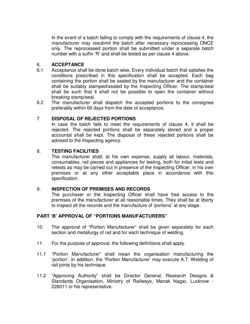
In the event of a batch failing to comply with the requirements of clause 4, the manufacturer may resubmit the batch after necessary reprocessing ONCE only. The reprocessed portion shall be submitted under a separate batch number with a suffix ‘R’ and shall be tested as per clause 4 above.
6. ACCEPTANCE 6.1 Acceptance shall be done batch wise. Every individual batch that satisfies the
conditions prescribed in this specification shall be accepted. Each bag containing the portion shall be sealed by the manufacturer and the container shall be suitably stamped/sealed by the Inspecting Officer. The stamp/seal shall be such that it shall not be possible to open the container without breaking stamp/seal.
6.2 The manufacturer shall dispatch the accepted portions to the consignee preferably within 60 days from the date of acceptance.
7. DISPOSAL OF REJECTED PORTIONS In case the batch fails to meet the requirements of clause 4, it shall be
rejected. The rejected portions shall be separately stored and a proper accountal shall be kept. The disposal of these rejected portions shall be advised to the Inspecting agency.
8. TESTING FACILITIES The manufacturer shall, at his own expense, supply all labour, materials,
consumables, rail pieces and appliances for testing, both for initial tests and retests as may be carried out in presence of the Inspecting Officer, in his own premises or at any other acceptable place in accordance with this specification.
9. INSPECTION OF PREMISES AND RECORDS
The purchaser or the Inspecting Officer shall have free access to the premises of the manufacturer at all reasonable times. They shall be at liberty to inspect all the records and the manufacture of ‘portions’ at any stage.
PART ‘B’ APPROVAL OF “PORTIONS MANUFACTURERS” 10. The approval of “Portion Manufacturer” shall be given separately for each
section and metallurgy of rail and for each technique of welding. 11. For the purpose of approval, the following definitions shall apply. 11.1 “Portion Manufacturer” shall mean the organisation manufacturing the
‘portion’. In addition, the ‘Portion Manufacturer’ may execute A.T. Welding of rail joints by his technique.
11.2 “Approving Authority” shall be Director General, Research Designs &
Standards Organisation, Ministry of Railways, Manak Nagar, Lucknow - 226011 or his representative.

12. PROCEDURE FOR APPROVAL OF “PORTION MANUFACTURERS” 12.1 The application for approval shall be submitted by the “Portion Manufacturer”
to the Approving Authority, indicating the rail for which portion is being offered and the welding technique.
12.2 Approving Authority, on receipt of such an application, shall forward
necessary proformae to be filled in by the applicant. The amount to be deposited shall also be intimated.
12.3 The applicant shall return the proformae, duly filled in, along with a demand
draft for the prescribed amount drawn in favour of Director (Finance), Research, Designs & Standards Organisation, Manak Nagar, Lucknow - 226011.
12.4 If the information submitted by the applicant is prima facie found to be
satisfactory, the Approving Authority shall inspect the premises of the applicant for assessment. If the assessment is satisfactory, tests and trials shall be undertaken by the Approving Authority.
12.5 Tests and trials for approval of “Portion Manufacturers”. 12.5.1 The Portion Manufacturer shall manufacture a batch of 150 ‘portions’ at his
own cost. Samples shall be drawn at random by the Approving Authority and the following laboratory tests shall be carried out at the Manufacturer’s works premises or at a laboratory mutually agreed upon between the manufacturer and the approving authority.
i) Six numbers of reaction tests will be conducted as per clause 4.1
ii) Twelve tests weld joints shall be made as per clause 4.2.2. The weld joints shall be subjected to following tests:-
a) Ultrasonic test on all the joints as per procedure laid down at
Annexure-1. b) Brinnell Hardness test on all the joints as per clause 4.2.2.
c) Transverse load and deflection test as per clause 4.2.3 on six randomly selected joints. d) Magnetic crack detection and macro examination on deep etched
longitudinal sections, across the weld on the remaining six joints. This examination shall not reveal any lack of fusion or cracks. Other welding defects, e.g. porosity, inclusions etc. shall not exceed 0.5% of the weld area in longitudinal section. The size of any individual defect shall not exceed 2mm diameter. The defects should not be interconnected and none of these shall extend upto the outer surface.
12.5.2 RETEST If the results of any of the tests referred to in clause 12.5.1 fail to meet the
requirements of the test, the technique shall be rejected. However, retest can be carried out at the request of the ‘Portion Manufacturer’ provided not more

than 2 joints have failed in ultrasonic testing and not more than one joint has failed in each of the other tests mentioned in clause 12.5.1.
For retest, same number of test specimens as mentioned for each test in
clause 12.5.1 shall be welded. None of the sample joint should fail in retest. 13. FATIGUE TEST 13.1 Fatigue testing of thermit welding technique shall be arranged by the
manufacturer at his own expense. Following principle shall be followed:- I) For 90UTS metallurgy : Anyone section out of 52kg/60kg (when both the
sections have been developed the lighter section should be selected for fatigue testing).
II) For 72 UTS metallurgy : Any one section out of 90R/52kg (when both the section have been developed the lighter section should be selected for fatigue testing).
III) Development of any other A.T. Welding technology such as wider gap, gas heating, Chrome Manganese/Head Hardened rails shall also be got separately fatigue tested before standardization. However, one section for one technique shall be required to be fatigue tested.
13.2 The weld samples shall be tested in a recognised laboratory/test centre for which prior approval of RDSO shall be necessary. 13.3 Following scheme shall be followed for fatigue testing of thermit welded rail
joints:- i) Three weld samples shall be made in presence of RDSO representatives. ii) The weld samples shall be made with one meter long new rail pieces to have
an overall length of 2.0m. The rail and joint shall be ultrasonically tested. iii) Testing shall be done for stress ranges of tensile 20 kg/mm2 to compressive4
kg/mm2 (these are the stresses on the bottom surface of rail foot). The test frequency shall be anyone frequency between 8.33 Hz to 12 Hz.
iv) A joint shall be deemed to have passed if it withstands a minimum of 2 million cycles.
v) The technique shall be deemed to have cleared fatigue test if all the three samples pass the above test.
13.4 Retest In case of failure of not more than one joint in the above test, retest can be carried out at the request of the portion manufacturer. For the purpose of retest, three more weld samples shall be made in presence of RDSO representative and subjected to the above test. The technique shall be deemed to have passed the fatigue test if all the three retest samples pass the test.

14 FIELD TRIALS 14.1 Subject to the results of the tests in clause 12 and 13 being satisfactory, service trials for a period of one year or till passage of 10 GMT traffic over the joint, whichever is earlier, shall be undertaken on 50 to 100 trial joints welded using the above batch of portion. For the purpose of field trials, an order shall be placed by the nominated Zonal Railway on the manufacturer for supply of portions as well as welding of trial joints. The trial joints shall be distinctly marked by painting letter “T” on the web of the rail beyond 300mm from the joints. During execution of trial welding at site, spoilt joints, if any, shall be cut and re-welded by the contractor at his own expense. 14.2 All the trial joints shall be ultrasonically tested soon after welding as per procedure at Annexure - 1. Upto a maximum of 2 % defective welds, shall be cut and re-welded by the manufacturer at his own expense. If more than 2 % joints are found defective, the trial shall be discontinued considering the technique to be unsatisfactory. All the defective joints shall be removed from track by the manufacturer at his own expense. 14.3 Failure of more than 2% joints during service trial will render the technique unacceptable. 15. The approving authority shall have free access to the premises of the portion manufacturer at all reasonable times. The portion manufacturer shall furnish all the technical data to the approving authority as and when call for. 16. PART –C: PROCEDURE FOR APPROVAL OF A.T. WELDING SUPERVISORS AND WELDERS 16.1 For the purpose of approval, the following definitions shall apply:- “Welding Supervisor” shall mean an individual engaged with portion manufacturer with adequate knowledge and competence for supervising and executing Alumino Thermic welding of rail joints. “Welder” shall mean an individual with adequate skill and competence for executing Alumino Thermic welding of rail joints at site. The approval of welding supervisors/welders for execution of Alumino �
Thermic welds at site shall be given separately for the following categories of welding techniques:- a) Welding of 72 UTS and 90 UTS rails with standard gap. b) Wide gap welding. c) Welding of 110 UTS and Head Hardened rails. 16.2 Competency certificates for welding supervisors and welders of the zonal Railways shall be issued by the Thermit Portion Plant of Northern Railway at Lucknow. Competency certificates for welding supervisors and welders of firms shall be issued by DG (M&C) RDSO, Lucknow.

16.3 Test weld joints will be made using any rail section at the discretion of the approving authority. Welding supervisors/welders found competent shall be deemed to be fit for A.T. welding of all rail sections for the particular category as per clause 16.1. For execution of test weld joints, the welding supervisor/welder desirous of obtaining approval shall have to utilise his own welding team, rails, implements and ‘portions’ procured from approved manufacturers. 16.4 The firm shall pay, in advance, charges for certification of supervisors/welders as per rates decided by RDSO for this purpose. Payment should be made through demand draft drawn in favour of Director(Finance), RDSO, Manak Nagar, Lucknow - 226011. 16.5 Six test welds shall be made by the welding supervisor/welder and his team for the particular category of welding technique (as per clause 16.1) for which approval is sought. Following tests shall be carried out at the sponsoring firms works premises or at RDSO, Lucknow:- a) Ultrasonic testing as per procedure mentioned at Annexure-1. Failure of more
than one test weld will disqualify the welding supervisor/welder. b) The ultrasonically sound joints will be subjected to following tests:-
i) Brinnell hardness test on all the test welds as per clause 4.2.2. ii) Transverse load and deflection tests on any three test welds as per
clause 4.2.3. iii) Magnetic crack detection and more examination of remaining three test
welds longitudinally sectioned across the weld as per clause 12.5.1 (ii) (d).
iv) Joint geometry as per clause 18.1 16.6 If the test results are satisfactory, a provisional competency certificate, valid for two years, shall be issued to the welding supervisor/welder on behalf of the sponsoring firm. The provisionally approved welding supervisor/welder competency shall be re-assessed by RDSO/TPP, Lucknow after two years for issue of competency certificate valid for five years. 16.6.1 For the purpose of reassessment, the welding supervisor/welder shall submit, to the approving authority, the following details duly countersigned by the concerned Assistant Engineer of Zonal Railway: - a) A record of joints welded/supervised by him. b) No. of joints failed in service. 16.6.2 Based on the above details and personal interview, the approving authority will issue competency certificate. Fresh competency certificate will have to be issued whenever there is a change in the process of welding or when a person who has been earlier trained and issued with a final competency certificate has not been executing welding for a period of more than 2 years or the work done by him has been rated as unsatisfactory. 16.6.3 Renewal of competency certificate will be made based on performance or actual testing.

16.6.4 A 10 character “Identification Code Number” shall be used for numbering of competency certificate and identification of supervisors and welders. The first three characters shall be alphabets which would indicate the agency (Railway or Firm) to which the supervisor or welder belongs, the next digit (S or W) would denote a supervisor or welder, the next three numbers would be allotted to the particular person (specific person number), next two numbers shall denote the year of issue of the competency certificate and the last alphabet (P or F) shall indicate whether it is “Provisional” or “Final” competency certificate. For example , NR0S00190F would indicate a welding supervisor of Northern Railway with specific person number 1, the Final competency certificate having been issued in the year 1990. The specific person number will be continuous for a Zonal Railway/Firm. The Organisation issuing competency certificates shall ensure that there is no duplication of the “Identification Code Number”. An annual list of valid competency certificates will be circulated by the agency issuing the competency certificates to the zonal railways. Zonal Railways should constantly update and maintain the list of supervisors and welders along with their identification code.
Part-D – Acceptance Test of Joints welded at site
17. EXECUTION OF WELDS AT SITE 17.1 Alumino-thermic welding of rails shall be executed at site only under the direct supervision of welding supervisor and by welder, both having valid competency certificate issued by RDSO/TPP, Lucknow (see Part ‘C’) 17.2 All Alumino - thermic welding work shall be executed with the use of weld trimmer and profile grinder. Additionally, rail tensors shall be used wherever work is done on welded rails. Note: In case of welding of old rails dispensations for not using weld trimmers and profile grinder shall be obtained from Chief Engineer. 18. ACCEPTANCE TESTS 18.1 Visual examination All the welded joints shall be cleaned and examined carefully to detect any visible defect like cracks, blow holes, shrinkage , mismatch, surface finish (smooth surface finish required) etc. Any joint which shows visible defect shall be declared defective. The bottom of the joint shall be checked by feeling with fingers as well as inspected with the help of a mirror for presence of `fins` at the parting line of the mould. If fin is observed in any joint, the joint shall be declared defective.” 18.2 Joint Geometry All the finished welded joints shall be checked to ensure that the joint geometry is within the following tolerances:- (i) Vertical misalignment +1.0mm (Measured at the end of -0.0mm 1 m straight edge) ( Fig.18.1 (a))

(ii) Lateral misalignment +0.5mm (Measured at the centre of 1m straight edge) (Fig.18.1 (b)) iii) Head finishing on sides + 0.3mm on gauge side (Measured at the centre of 10cm straight edge (Fig.18.1 (c)) iv) Finishing top table surface +0.4mm (Measured at the end of 10cm straight -0.0mm edge (Fig.18.1 (d)) Note: Dispensation for joint geometry, in case of old rails may be permitted by Chief Engineer. The details of geometry of each joint shall be jointly signed by the firm’s and Railway’s representative and kept as a record. Any joint found not conforming to the above stipulations shall be cut and rewelded, free of cost, by the firm. 18.3 Ultrasonic testing All the welded joints shall be ultrasonically tested by the Railways as per the procedure given at Annexure -1. This testing shall be completed as early as possible after welding but before the welding team leaves welding site. All the joints which are found to be defective shall be cut and re-welded by the firm at its own cost. Where one bad joint is required to be replaced by two new joints, the entire cost of both the joints shall be borne by the firm. Such re-welded joints shall also be tested ultrasonically and if found defective, shall again be cut and re-welded free of cost. However, the number of defective welds shall not exceed 2 % of the total number of joints welded against a particular contract. 18.4 Sample Test Joints: One out of every 100 joints welded per batch shall be selected at random by the purchaser or by the inspecting officer within one month of welding and subjected to hardness and transverse test as per clause 4.2 and the joint shall comply with the provisions laid down therein. 18.4.1 In the event of the failure of sample test joint in any of the requirements of this specification, the Railway will be at liberty to suspend further welding. However, two more randomly selected joints from the same lot of 100 joints shall be subjected to re-tests as per clause 4.2. Both the joints should clear all the tests. If the report is also not satisfactory, further welding of joints shall be suspended until the firm has examined the welding technique and satisfies the requirements of Clause 4 by welding one test joint. The clearance for re-commencement of welding shall be given by RDSO.
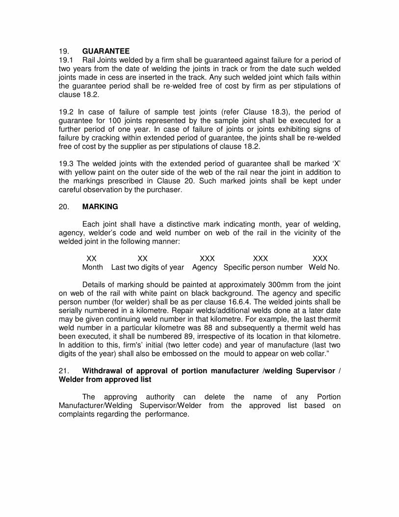
19. GUARANTEE 19.1 Rail Joints welded by a firm shall be guaranteed against failure for a period of two years from the date of welding the joints in track or from the date such welded joints made in cess are inserted in the track. Any such welded joint which fails within the guarantee period shall be re-welded free of cost by firm as per stipulations of clause 18.2. 19.2 In case of failure of sample test joints (refer Clause 18.3), the period of guarantee for 100 joints represented by the sample joint shall be executed for a further period of one year. In case of failure of joints or joints exhibiting signs of failure by cracking within extended period of guarantee, the joints shall be re-welded free of cost by the supplier as per stipulations of clause 18.2. 19.3 The welded joints with the extended period of guarantee shall be marked ‘X’ with yellow paint on the outer side of the web of the rail near the joint in addition to the markings prescribed in Clause 20. Such marked joints shall be kept under careful observation by the purchaser. 20. MARKING Each joint shall have a distinctive mark indicating month, year of welding, agency, welder’s code and weld number on web of the rail in the vicinity of the welded joint in the following manner: XX XX XXX XXX XXX Month Last two digits of year Agency Specific person number Weld No. Details of marking should be painted at approximately 300mm from the joint on web of the rail with white paint on black background. The agency and specific person number (for welder) shall be as per clause 16.6.4. The welded joints shall be serially numbered in a kilometre. Repair welds/additional welds done at a later date may be given continuing weld number in that kilometre. For example, the last thermit weld number in a particular kilometre was 88 and subsequently a thermit weld has been executed, it shall be numbered 89, irrespective of its location in that kilometre. In addition to this, firm's’ initial (two letter code) and year of manufacture (last two digits of the year) shall also be embossed on the mould to appear on web collar.” 21. Withdrawal of approval of portion manufacturer /welding Supervisor / Welder from approved list The approving authority can delete the name of any Portion Manufacturer/Welding Supervisor/Welder from the approved list based on complaints regarding the performance.

Recent Developments
in AT Welding

Recent development in Alumino-thermic welding technology of rails
Alumino-thermic welding is widely used process for in-situ welding of rails all over the world and the same is the case with Indian Railways. Presently on Indian Railways approximately 5.5 lakh AT welds are being done every year. Welding joints executed by alumino thermic process are the weakest of all the welds and therefore prone for fractures. As per the statistics issued by RDSO, about 60% fractures occurring on Indian Railway are attributed to alumino-thermic joints.
To reduce the total number of AT welding fractures quality of AT welding technique needs improvement. Several developments have taken place with a view to improve the quality of alumino-thermic weld such as: i) AT welding technique with three piece mould. ii) AT welding technique with compressed air petrol pre-heating. iii) AT welding technique with Oxy-LPG fuel mixture. iv) AT welding technique with 60/52 kg combination joint. v) Wide gap (75 mm) welding technique for fracture repair. AT welding techniques with three piece mould
At present AT welding of rail is being carried out with two piece mould. The detailed procedure of fixing of mould and its luting has been specified in the Manual. However, sometimes due to improper fixing of mould by untrained welders, the fins are created at the bottom of welds. The presence of fins at the bottom of AT welds acts as stress raiser for initiation of half moon fatigue cracks thereby reducing the life of the welds. To avoid the presence of fins, AT welding technique for 52 kg/60 kg, 90 UTS rails with three piece moulds has been developed. It is expected that three piece moulds welding will be adopted on Indian Railways in a big way.
Three piece mould

AT welding with compressed air petrol pre-heating
The compressed air petrol pre-heating technique, with preheating time of 4.0 and 4.5 minutes for 52 kg. (90 UTS) and 60 kg. (90 UTS) rails respectively, has been developed with a view to reduce preheating time and the heat affected zone. At present, the pre-heating time for SKV welding technique is 10 minutes for 52 kg. (90 UTS) rail section and 12 minutes for 60 kg (90 UTS) rail section. Therefore, compressed air-petrol pre-heating technique offers considerable reduction in preheating time and thereby saving of precious block time.
The Heat Affected Zone (HAZ) in a weld is the most vulnerable zone of AT
weld and most of the AT weld failures take place through HAZ only. It is always desirable to have minimum possible width of HAZ. With the use of compressed air petrol technique, HAZ is reduced considerably because of shorter preheating time, thus increasing the service life of AT welded joint.
AT welding technique with Oxy-LPG fuel mixture
The Oxy-LPG fuel mixture can reduce the pre-heating time to 2-3 minutes because of the intensity of heat application and also resulting in the narrower HAZ. As the pre-heating time is considerably reduced, the requirement of block for executing the welding is also reduced. However this technique not approved by RDSO for use in in-situ welding. AT welding for combination joint
On every railway system, more than one rail section is used depending upon vintage of rails and type of traffic. Moreover, at times, rails of two or more cross sections are laid on the same route. Often, it is required to insert glued joints, points & crossings or SEJs of rails having different cross-section. Earlier combination fish plates were used for joining of rails having different cross-sections. But, the combination fish plates result in battering, hogging of rails ends and also require periodical watch & maintenance.
An ideal answer to this problem is to replace the junction of different cross section of rails with forged junction of combination rails. But, there forged rails are required to be imported from foreign countries and which naturally cost much. As an alternative, AT Welding technique for welding of 60kg (90UTS)/52 kg (90UTS) rails joints has been developed. The use of this welding technique has resulted in improved riding comfort and improved maintainability.
Combination joint

Wide Gap (75 mm) Welding Technique AT present, the fractured rail/welds have to be replaced by long rail closure. This rail piece is inserted in the track after creating a gap of about same length and welded with the existing rail on both the ends. Thus, in order to remove one defective/fractured AT weld, two AT welds are created. The whole process of replacing the fractured/defective weld with closure rail piece involves considerable amount of man power and block time as well as wastage of rails. With the development of 75mm wide gap welding technique, the defective/fractured weld can be replaced with a single 75mm wide gap AT weld thus resulting in considerable saving of man power and block time required for execution of AT welds.
The major procedural difference between the standard 25mm gap welding and 75mm wide gap welding arise mainly due to larger quantity of thermit steel in later. Because of increased volume, the heat content of thermit steel is greater which leads to slower solidification. Hence, temperature dependent post welding activities such as demoulding, trimming and grinding are slightly delayed. As a result, time required for execution of wide gap welding joint is slightly longer than one standard 25mm weld, but still lower than the time required for two 25mm standard weld.
Advantages of wide gap welding technique are:
� A single defective/fractured weld/rail can be replaced on one to one basis.
� It will not require insertion of a 6m rail piece.
� Less number of traffic blocks will be required.
� Lesser number of weld failures due to reduced number of welds hence
improved safety.
� Saving in requirement of joggled fishplates.
� Lesser number of wooden blocks will be required.
� Substantial saving of manpower, material and increased availability of
track for running of trains.
Wide gap weld

Project for acquiring state of the art alumino-thermic welding technology
With the objective of improvement in the quality of AT weld, a work to acquire state of the art technology to improve quality of Alumino thermic welds has been sanctioned by Railway Board under SRSF costing Rs. 30 crores. The objective of the project is to acquire the state of the art technique of alumino thermic welding as a complete package encompassing entire gamut of activities involved in the welding. The package would involve improvement in the consumables and equipment, training of welders and supervisors and the latest technological advances in this field from global leaders. It is expected that the following aspects of alumino thermic welding would get upgraded.
Reduction in element of human error
This is expected through Use of One-shot Crucible, Use of Auto Thimble, Acquiring Skills
One-shot crucible
Used only for one weld, the one shot crucible is made from a refractory compound agglomerated by means of synthetic resin. The thermic factor of this crucible is notably better than the conventional crucible and its use results in cleaner steel and consistent weld quality.
The need for accurate adjustment of crucible on its frame is eliminated. The one shot crucible comes factory packaged with the portion, crucible and automatic thimble. Various features of one shot crucible are:
� Light weight (14.5 Kg) � Simple 4 step installation- align rail, install moulds, preheat rail and ignite � Durability-the crucible is packed in an external protective sand layer. � Environmentally sealed against outside elements. � Moulds are available in both 2 or 3 piece type.
One shot crucible

Auto thimble
By having a constant and reliable crucible to produce the weld metal, quality of the weld is increased substantially mainly because of the fact that the thermal balance of the alumino-thermic reaction always remains the same. This ensures a highly uniform tapping temperature, which is one of the key quality parameter for alumino-thermic welding as for any steel production process.
Auto Thimble The use of auto thimble ensures that the pouring commences at the correct temperature. It allows tapping at pre-determined temperature thereby eliminating errors associated with manual tapping i.e. early or late tapping. In case of early tapping, slag may accompany weld steel. On the other hand, in case of late tapping, weld steel may loose heat which may cause inadequate fusion.
With use of auto thimble safety of personnel is also ensured as no person
is required near the crucible thus eliminating the chances of injury.

Salient feature of
AT Welding
Manual
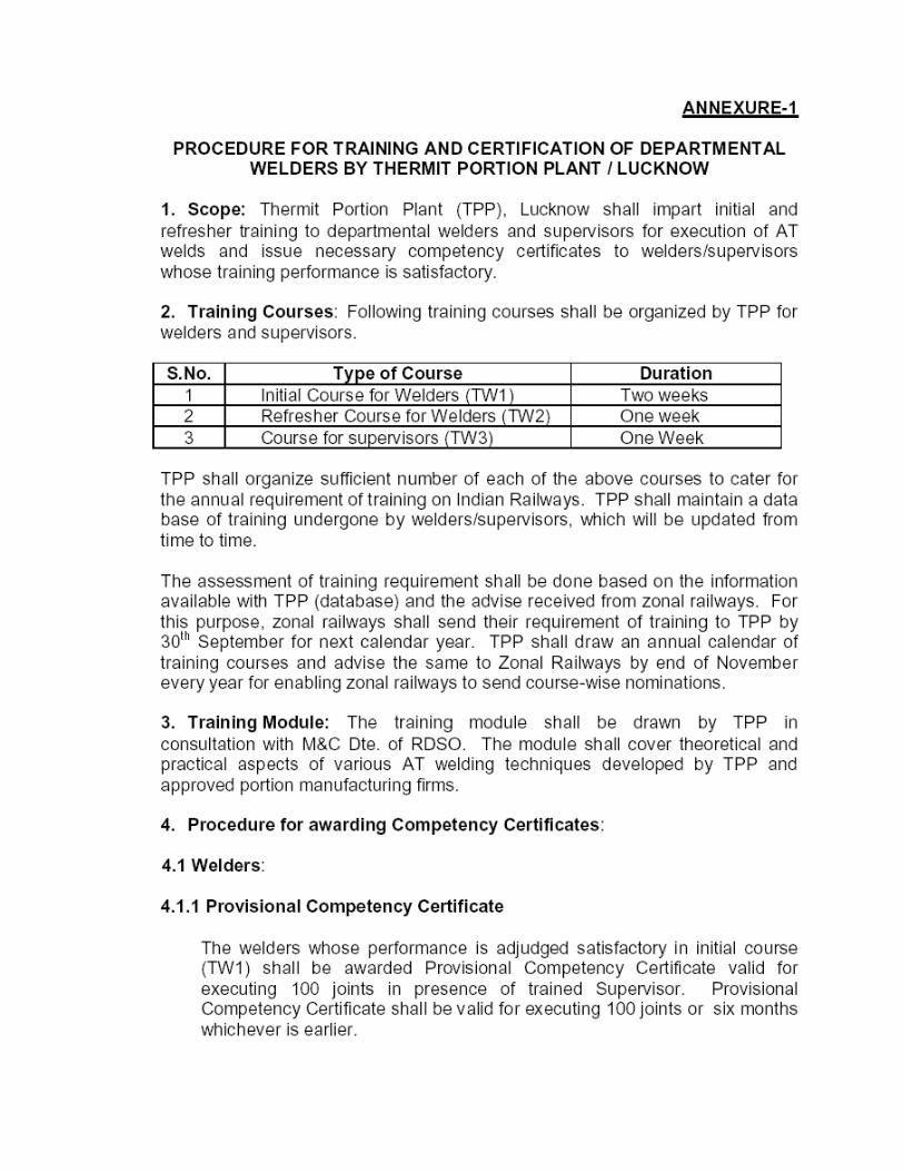


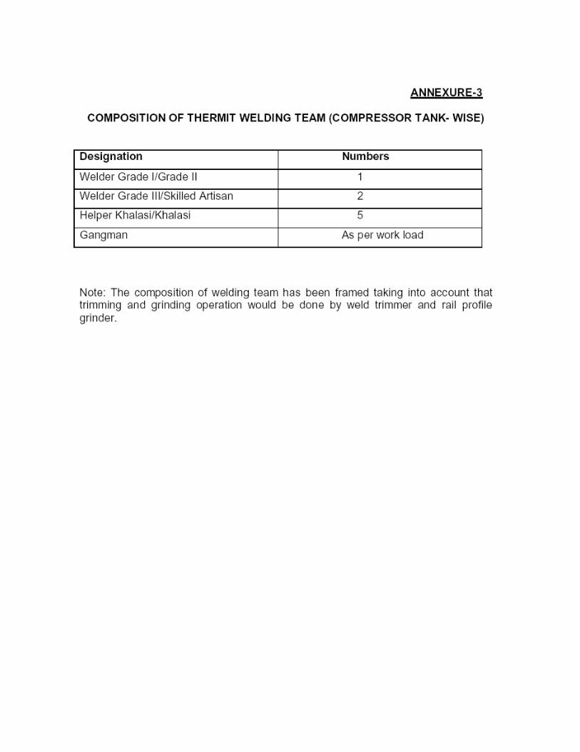

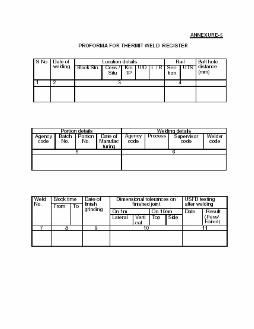
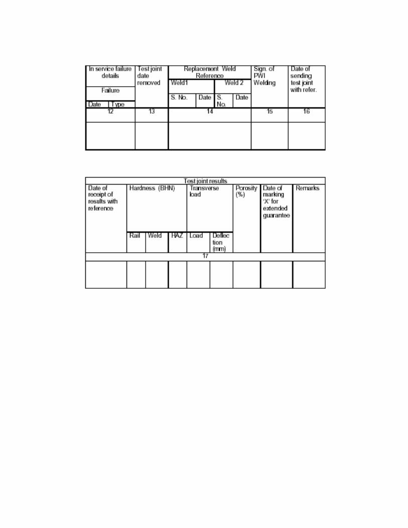


Check list during
AT welding


Training Module

TRAINING MODULE
The minimum qualification of the welders shall be matriculation. Subjects to be
included in the training of welders and supervisors to are listed below.
(i) Principle of thermit welding and its formula
Need for AT welding and its advantage.
(ii) Storage preservations of portions & mould
Suitable storage conditi0n for portion & mould to void contact from moisture,
shelf life of portion and its use after shelf life. Information on portion bag &
ticket, colour scheme for portion.
(iii) Thermit Portion.
Different main ingredients used in manufacture of AT portion.
(iv) Inspection of ails before welding.
Bolt hole distance from rail end, corrosion, battering minimum length of rail,
flow of metal along gauge side, wear and USFD of old rail.
(v) Pre-heating equipment
Air-Petrol burner, Compressed Air Petrol blower, Oxy-LPG heating system,
preheating time & pressure.
(vi) Rails and their alignment.
Different type of rails according to section and quality, knowledge of
alignment and precautions.
(vii) Thermit welding equipment and accessories
List of necessary equipment such as crucible, weld trimmer, grinder, crucible
stand etc.
(viii) Luting Sand & Mould
Quality of luting sand & test in field and its effect on the quality of joint.
Condition of mould fixing of mould, use of Zircon wash.
(ix) Reaction mould waiting time & chipping of weld metal.
Judgment of reaction, reaction time for different gap, importance of mould
waiting time, weld metal trimming with weld trimmer.
(x) Block period & train passing time:
Minimum block period required, importance of riser, its breaking time, train
passing time after tapping, precaution for newly welded joints.
(xi) Maintenance of crucible
Charging, repair, thimble charge etc., and its effectiveness with joint.

(xii) AT Welding defects cause & their remedial measures.
Different type of defects in AT weld joints, their causes and the precautions to
be taken to avoid the welding defects, geometry of the joint.
(xiii) Grinding & Painting
Use of profile grinder, tolerance, cleaning, painting procedure, numbering,
visual examination of weld profile.
(xiv) Latest development in AT welding
Welding of HH rail, alloy steel rail, wide gap, compound joint etc., use of three
piece mould & auto thimble.
(xv) Safety Aspects
Precaution to be taken by welder during execution, use of goggles, hand gloves
& apron.
(xvi) Different types of gaps
Knowledge of different gap, its affect on quality of AT joint.

THERMIT WELDING TRAINING CENTRE, Vijayawada, South Central Railway
Time table for TW-I(Initial course for welders-Duration two weeks)
Ist WEEK
Days Ist session
9.00-11.00hrs
11.00-
11.15hrs
IInd session
11.15-13.00hrs
13.00-
14.00hrs
14.00-15.30hrs
Practicals
15.30-
15.45hrs
15.45-16.30
Practicals
1st Day Registration and allotment of
hostel accommodation
Discussion on field
problems
Visit of model room
Visit of model room
2nd Day
Principle and advantages of
A.T.Welding
Principle and
advantages of
A.T.Welding
Demo of AT Welding
vertical &lateral
alignment, selection of
rails
Demo of AT
Welding, welding
gap, fixing of
mould
3rd Day
Thermit portion
composition,identification,
sealing,packing,storage&handling
Selection of rails &
precautions for
selection
Demo of AT Welding
Crucible charger repair
and fixing of crucible
Demo of AT
Welding
4th Day
Welding equipments
consumables& their handling
Practical demo of
A.T.welding.
Cutting of rails with cutting machine
Practical demo of
A.T.welding
Of rail joints
Practical demo of
A.T.welding
Of rail joints
5th Day
Dos & Don’ts of A.T.Welding
Practical demo of
A.T.welding
Of rail joint
Practical demo of
A.T.welding
Of rail joint
Practical demo of
A.T.welding
Of rail joint
6th Day Practical demo of
A.T.welding
Of rail joint
T
E
A
B
R E
A
K
Practical demo of
A.T.welding
Of rail joint
L
U
N
C
H
B
R E
A
K
Half day
T
E
A
B
R E
A
K
Half day

THERMIT WELDING TRAINING CENTRE, Vijayawada, South Central Railway
Time table for TW-I(Initial course for welders-Duration two weeks)
IInd WEEK
Days
Ist session
9.00-11.00hrs
11.00-11.15hrs
IInd session
11.15-13.00hrs
13.00-14.00hrs
14.00-15.30hrs
Practicals
15.30-15.45hrs
15.45-16.30
Practicals
7th Day Pre,During&post
welding
precautionsTrack
protection and
safety
Execution of
A.T.Weld by
trainees
Execution of
A.T.Weld by
trainees
Execution of
A.T.Weld by
trainees
8th Day Precautions to be
taken during
welding
Precautions to be
taken during
welding
Execution of
A.T.Weld by
trainees
Execution of A.T.Weld by
trainees
9th Day
Lecture on
A.T.Weld defects
Lecture on
A.T.Weld defects
Execution of
A.T.Weld by
trainees
Execution of
A.T.Weld by
trainees
10th Day Lecture on
Tests on at weld
joints
USFD TESING
OF ATWELD&
action to be taken
Execution of
A.T.Weld by
trainees
Execution of
A.T.Weld by
trainees
11th day BHN testing of AT Weld joints
Breaking load testing of AT
Weld joints
Review and revision of
training
Review and revision of
training
12th Day Interview and
issue of
competency
certificate
T
E
A
B
R
E
A K
Interview and
issue of
competency
certificate
L
U
N
C
H
B
R
E A
K
Half day
T
E
A
B
R
E
A K
Half day

THERMIT WELDING TRAINING CENTRE, Vijayawada, South Central Railway
Time table for TW-II (Refresher course for welders-Duration ONE weeks)
Days Ist session
9.00-11.00hrs
11.00-
11.15hrs
IInd session
11.15-13.00hrs
13.00-
14.00hrs
14.00-15.30hrs
Practicals
15.30-
15.45hrs
15.45-16.30
Practicals
1st day Registration and
allotment of hostel
accommodation
Discussion on field problems
Visit of model
room
Visit of model
room
2nd Day
Principle and
advantages of
A.T.Welding
Thermit portion and other
consumables composition,
identification,
sealing,packing,storage&handling
Demo of AT
Welding
vertical
&lateral
alignment,
selection of
rails
Demo of AT
Welding,
welding gap,
fixing of mould
by busing
mould fitted
jig.
3rd Day
Precautions to be taken
during A.T.Welding
Pre and post welding precautions
in A.T.welding
Demo of AT
Welding of rail joints by using
3-piece mould
and CAP
preheating
Demo of AT
Welding of rail joints by using
3-piece mould
and CAP
preheating
4th day
Dos & Don’ts of
A.T.Welding
Demo of AT Welding of rail
joints by using 3-piece mould and
CAP preheating
Practical demo
of A.T.welding
Of rail joints
Practical demo
of A.T.welding
Of rail joints
5th Day
Lecture on AT Weld
defects
Lecture on
Tests on AT Weld joints and
USFD TESTING
Testing of
welds for
,BHN
&Breaking
load
Review and
revision of
training
6th Day Interview and issue
of FINAL
competency
certificate
T
E
A
B
R
E
A
K
Interview and issue of
FINAL competency
certificate
L
U
N
C
H
B
R
E
A
K
Half day
T
E
A
B
R
E
A
K
Half day
THERMIT WELDING TRAINING CENTRE, Vijayawada, South Central Railway

Time table for TW-III (Course for Supervisors-Duration ONE weeks)
Days Ist session
9.00-11.00hrs
11.00-
11.15hrs
IInd session
11.15-13.00hrs
13.00-
14.00hrs
14.00-15.30hrs
Practicals
15.30-
15.45hrs
15.45-16.30
Practicals
7th day
Registration and
allotment of hostel
accommodation
Discussion on field problems
Visit of model
room
Visit of model
room
8th day
Principle and
advantages of
A.T.Welding
Thermit portion and other
consumables composition,
identification,
sealing,packing,storage&handling
Demo of AT
Welding
vertical
&lateral
alignment, selection of
rails
Demo of AT
Welding,
welding gap,
fixing of mould
by busing mould fitted
jig.
9th day
Precautions to be taken
during A.T.Welding
Pre and post welding precautions
in A.T.welding
Demo of AT
Welding of rail
joints by using
3-piece mould
and CAP
preheating
Demo of AT
Welding of rail
joints by using
3-piece mould
and CAP
preheating
10th Day
Lecture on AT Weld
defects
Lecture on AT Weld defects
Practical demo
of A.T.welding
Of rail joints
Practical demo
of A.T.welding
Of rail joints
11th day
Dos & Don’ts of A.T.Welding
Lecture on
Tests on AT Weld joints and USFD TESTING
Testing of
welds for ,BHN
&Breaking
load
Review and
revision of training
12th day
Written
examination
T
E
A
B
R
E
A
K
Interaction with trainees
and issue of FINAL
competency certificate
L
U
N
C
H
B
R
E
A
K
Half day
T
E
A
B
R
E
A
K
Half day


