All-Optical 40 Channels Regenerator Based on Four- Wave Mixing Salman Ghafoor ( [email protected]) National University of Sciences and Technology School of Electrical Engineering and Computer Science https://orcid.org/0000-0002-1031-4471 Muhammad Usama Khan National University of Sciences and Technology School of Electrical Engineering and Computer Science Aamir Gulistan Simula Research Laboratory AS Ahmad Salman National University of Sciences and Technology School of Electrical Engineering and Computer Science Syed M. Hassan Zaidi National University of Sciences and Technology School of Electrical Engineering and Computer Science Research Article Keywords: Optical regenerators , Four Wave Mixing , Multi-channel regeneration Posted Date: April 27th, 2021 DOI: https://doi.org/10.21203/rs.3.rs-434821/v1 License: This work is licensed under a Creative Commons Attribution 4.0 International License. Read Full License Version of Record: A version of this preprint was published at Telecommunication Systems on November 9th, 2021. See the published version at https://doi.org/10.1007/s11235-021-00855-1.
Transcript
All-Optical 40 Channels Regenerator Based on Four-Wave MixingSalman Ghafoor ( [email protected] )
National University of Sciences and Technology School of Electrical Engineering and Computer Sciencehttps://orcid.org/0000-0002-1031-4471
Muhammad Usama Khan National University of Sciences and Technology School of Electrical Engineering and Computer Science
Aamir Gulistan Simula Research Laboratory AS
Ahmad Salman National University of Sciences and Technology School of Electrical Engineering and Computer Science
Syed M. Hassan Zaidi National University of Sciences and Technology School of Electrical Engineering and Computer Science
Research Article
Keywords: Optical regenerators , Four Wave Mixing , Multi-channel regeneration
Posted Date: April 27th, 2021
DOI: https://doi.org/10.21203/rs.3.rs-434821/v1
License: This work is licensed under a Creative Commons Attribution 4.0 International License. Read Full License
Version of Record: A version of this preprint was published at Telecommunication Systems on November9th, 2021. See the published version at https://doi.org/10.1007/s11235-021-00855-1.
Noname manuscript No.(will be inserted by the editor)
All-Optical 40 Channels Regenerator Based on
Four-Wave Mixing
Salman Ghafoor*, Muhammad UsamaKhan, Aamir Gulistan, Ahmad Salmanand S. M. Hassan Zaidi
Received: date / Accepted: date
Abstract We have proposed a novel multi-channel regeneration scheme forwavelength division multiplexed systems, which is based on four wave mixingin a highly nonlinear fiber. A 40-channel wavelength division multiplexed sig-nal having data rate of 10 Gbps per channel is divided into five groups. Eachgroup is composed of eight channels and requires a single pump laser sourceand two segments of highly nonlinear fibers to regenerate the eight channels.Therefore, our proposed scheme requires four times lesser number of highlynonlinear fibers compared to the previously proposed techniques. The regen-eration performance for all the forty channels is presented through bit errorrate analysis at low optical signal to noise ratio of 15 dB. Simulation resultsshow that an average improvement of 4.246 dB, 3.935 dB, 3.72 dB, 2.71 dBand 2.593 dB in receiver sensitivities has been observed for all the five groupsof channels, respectively.
Keywords Optical regenerators · Four Wave Mixing · Multi-channelregeneration
1 Introduction
Optical fiber technology has revolutionised the concept of information trans-fer over long distances during the past years. There has been an enormous
Salman Ghafoor (Corresponding author)School of Electrical Engineering and Computer Science, National University ofSciences and Technology (NUST), Sector H-12, Islamabad, Pakistan. E-mail:[email protected]
Muhammad Usama Khan, Ahmad Salman and S. M. Hassan ZaidiSchool of Electrical Engineering and Computer Science, National University of Sciencesand Technology (NUST), Sector H-12, Islamabad, Pakistan.
Aamir GulistanSimulaMet, Simula Research Laboratory, Pilestredet 52, 0167. Oslo, Norway.
2Please give a shorter version with: \authorrunning and \titlerunning prior to \maketitle
increase in the information carrying capacity of optical fibres from just fewkbps to Tbps in just a few decades. These tremendous achievements have notstopped here, as millions of new customers and new devices are being added tothe network annually. This evolution is a remarkable achievement for the re-search community, yet raising the challenge for network operators as advancedtechnologies such as 5G networks, Ultra high definition (HD) streaming ser-vices, and the development of new internet of things (IoT) based devices areputting a huge strain on the network [1]. It is expected that 50 billion de-vices will be connected to the internet after the availability of 5G technologypublicly [2]. To cope with such a huge bandwidth demand, the emphasis isnot only on advance network layer protocols but also on advancement in theoptical communication devices [3].
Dense Wavelength Division Multiplexing (DWDM) is one of the suitablesolutions for the transmission of multiple channels over long distances [4]. How-ever, there are certain challenges due to amplified spontaneous emission (ASE)noise [5] and the use of large number of WDM channels which leads to signaldistortion and cross talk [6]. Currently, regeneration is carried out by convert-ing the optical signal into an electrical signal, wherein the regeneration processencompasses re-amplification, re-shaping and re-timing. Thereafter, the signalis again converted back into the optical domain for onward transmission. Thewhole process is time consuming since it involves multiple conversions and isnot scalable to higher modulation schemes and high data rates [7]. The needfor efficient, optimized and low-cost optical devices is evident for regenerationof signals. All-optical signal regeneration is the key technology to improve thesignal quality by restoring the original shape of the optical signals [8]. All op-tical regeneration results in reduction of noise in the optical signals for highcapacity optical links at a low cost and low power consumption [9]. Basedupon their functionality, optical regenerators are generally of two major typesthat are 2R- and 3R-regenerators. 2R-regenerators have the functionality ofre-amplification and re-shaping of the pulse, whereas, 3R-regenerators also addthe functionality of re-timing [10], [11].
A 2R-regeneration method is discussed in [12], where the technique isbased upon self phase modulation (SPM) and offset filtering using a 2 m longBismuth Oxide fiber with an ultra-high nonlinearity of γ = 110 W−1/Km.Similar demonstrations of optical 2R-regeneration achieved by vertical micro-cavity mirror based multiple quantum-well saturable absorber is presented in[13]. The proposed device performs regeneration through a pigtailed saturableabsorber chip implemented with eight independent fibers using a cost effec-tive coupling technique. Rochette et. al. demonstrated a 3R-regenerator usingCross-Phase Modulation (XPM), where, zeros and ones of the noisy signalare imprinted on to the clock signal after passing through a highly nonlinearfiber (HNLF). Improvement of 4 dB optical signal to noise ratio (OSNR) atBER = 10−10 was recorded at a data rate of 40 Gbps. However, the proposedtechnique is demonstrated for the regeneration of a single channel only [14].Croussore et. al. proposed an all-optical phase regenerator using SymmetricPump Phase-Sensitive Amplifier (SP-PSA) [15]. SP-PSA is used for phase re-
All-Optical 40 Channels Regenerator Based on Four-Wave Mixing 3
generation of a phase-noise degraded non-return-to-zero differential phase-shiftkeying (DPSK) signal using bismuth oxide highly nonlinear fiber (Bi-HNLF).Recently, four channel phase regeneration of quadrature phase shift keying(QPSK) signals using phase sensitive amplification is demonstrated in [16],[17]. The technique uses Four wave mixing (FWM) in a HNLF to generate thecorresponding three harmonic conjugates that are optically combined to real-ize phase regeneration by coherent addition. Experimental results showed thatthe OSNR can be improved up to 3 dB. Contestabile et. al. experimentallyinvestigated all-optical regeneration of constant envelope alternate modula-tion format signals at 40 Gbps using hard limiting amplification in a saturatedsemiconductor optical amplifier (SOA). This technique is efficient when Po-larization Shift Keying and Frequency Shift Keying signal formats are used,whereas, the improvement of OSNR is limited for Non-Return-to-Zero (NRZ)DPSK signal format [18]. Sixteen channels are regenerated using a Group-delay-managed (GDM) medium that is made by concatenation of ′N ′ numberof fibers and periodic group-delay device (PGDD) unit cells [19]. The proposeddesign has a complex structure that is implemented in different stages.
Most of the techniques discussed above regenerate a single optical chan-nel. The techniques proposed for multiple channels are generally complex andrequire specialized equipment. Therefore, there is a need for a multi-channelregeneration technique that uses off-the-shelf components and simple opticalsignal processing. In this study, we have proposed such a technique by em-ploying FWM in a HNLF. Our proposed technique requires a single span ofdispersion shifted HNLF to simultaneously regenerate four optical channels.We have divided the incoming WDM signal into groups of eight channels. Eachgroup requires a single continuous wave (CW) pump source and two spans ofHNLFs. The center frequency of the pump laser source in each group is chosensuch that the multiple sidebands generated as a result of FWM do not overlapwith each other at the output of the HNLF. Our proposed technique is suit-able for WDM signals having large number of channels such as a forty channelsystem. For example, for a forty channel WDM system, the total number ofpump sources and HNLF segments required for regeneration based on ourtechnique are five and ten, respectively, compared to forty pump sources andforty HNLF segments required for previously proposed techniques. Therefore,the proposed technique is cost-efficient, employs off-the-shelf components andis simple to implement. Section-2 of the paper discusses the working principleof the proposed technique while Section-3 presents the simulation setup thatis designed using the commercial tool OptiSystem 17. Section-4 of the paperpresents the performance analysis while Section-5 discusses the conclusions.
2 Working Principle
The working principle of the proposed regeneration scheme is based on FWMin a HNLF. A pulsed optical signal is coupled with a CW high power pump,as illustrated in Fig. 1. The combined optical signal whose field envelope is
4Please give a shorter version with: \authorrunning and \titlerunning prior to \maketitle
fp
fs
fp
fs
FWM
f1
f2
f-1
f-2
fn = fp + n(fs-fp)
Inte
nsity
Frequency
Sid
eb
an
d I
nte
nsity
Pump
Signal
Frequency
Signal
Pump
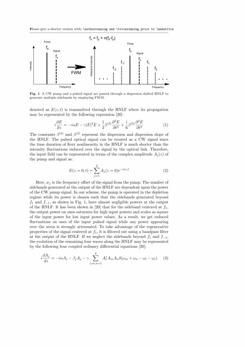
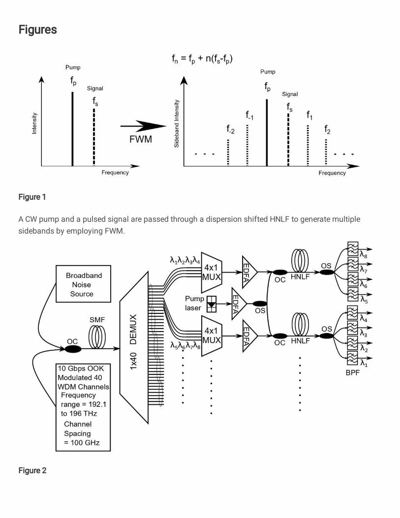
Fig. 1 A CW pump and a pulsed signal are passed through a dispersion shifted HNLF togenerate multiple sidebands by employing FWM.
denoted as E(z, t) is transmitted through the HNLF where its propagationmay be represented by the following expression [20]:
i∂E
∂z= −iαE − γ|E|2E +
1
2β(2) ∂
2E
∂t2+
i
6β(3) ∂
3E
∂t3(1)
The constants β(2) and β(3) represent the dispersion and dispersion slope ofthe HNLF. The pulsed optical signal can be treated as a CW signal sincethe time duration of Kerr nonlinearity in the HNLF is much shorter than theintensity fluctuations induced over the signal by the optical link. Therefore,the input field can be represented in terms of the complex amplitude Aj(z) ofthe pump and signal as:
E(z = 0, t) =
2∑
j=1
Aj(z = 0)e−iwjt (2)
Here, wj is the frequency offset of the signal from the pump. The number ofsidebands generated at the output of the HNLF are dependent upon the powerof the CW pump signal. In our scheme, the pump is operated in the depletionregime while its power is chosen such that the sidebands generated beyondf1 and f−1, as shown in Fig. 1, have almost negligible powers at the outputof the HNLF. It has been shown in [20] that for the sideband centered at f1,the output power on ones saturates for high input powers and scales as squareof the input power for low input power values. As a result, we get reducedfluctuations on ones of the input pulsed signal while any power appearingover the zeros is strongly attenuated. To take advantage of the regenerativeproperties of the signal centered at f1, it is filtered out using a bandpass filterat the output of the HNLF. If we neglect the sidebands beyond f1 and f−1,the evolution of the remaining four waves along the HNLF may be representedby the following four coupled ordinary differential equations [20]:
idAj
dz= −iαAj − βjAj − γ
4∑
l,m,n=1
A∗
lAmAnδ(ωm + ωn − ωl − ωi) (3)
All-Optical 40 Channels Regenerator Based on Four-Wave Mixing 5
Here, δ represents the Kronecker delta and is either 1 or 0, depending uponthe values of the frequencies ω, and βj represents the propagation constantsthat may be expressed as:
βj = (β(2)
2)ω2
j + (β(3)
6)ω3
j (4)
It may be observed from Eq. 3 that FWM between the pump and the signalresults in the generation of multiple sidebands at the output of the HNLF.These sidebands are spaced at frequencies that are equal to the frequency dif-ference between the pump and the signal. For single channel regeneration, asimple bandpass filter centered at f1 may be used to filter out the regeneratedsignal. However, the situation becomes complex when we have more than oneoptical channel at the input of the HNLF. In this scenario, the equally spacedoptical sidebands of different channels will overlap in frequency and will resultin channel distortion. Therefore, to the best of our knowledge, FWM based re-generation for multiple channels has not been demonstrated until now. To copewith this issue, we have proposed a novel scheme that regenerates four opticalchannels simultaneously by employing a single dispersion shifted HNLF anda CW pump. The center frequency of the CW pump is chosen such that eachchannel is spaced at a different frequency from the CW pump before FWM isperformed. Therefore, the multiple sidebands generated due to FWM wouldbe centered at different frequencies and can be easily filtered. Furthermore,the power of the CW pump is chosen such that it is almost depleted whilegenerating the sidebands f1 and f−1.
3 System Architecture
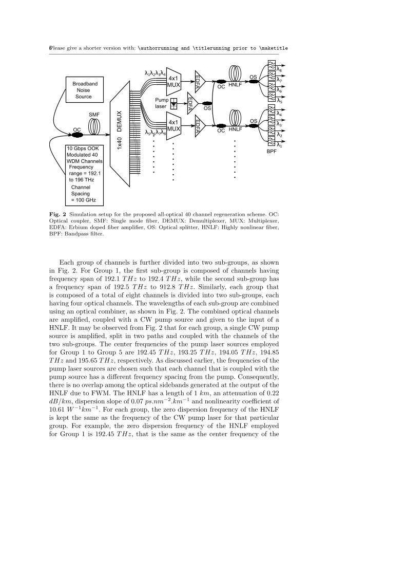
Fig. 2 shows the simulation setup of our proposed scheme. Forty optical chan-nels, each having a data rate of 10 Gbps are generated at the transmitter. Thefrequency range of the channels span from 192.1 THz to 196.0 THz with achannel spacing of 100 GHz in order to reduce cross-talk among the chan-nels. On-Off keying (OOK) modulation is used where the pulse width of eachchannel is 15 ps. Broadband ASE noise is added to the 40-channel WDM sig-nal to reduce the OSNR of each channel, as shown in Fig. 2. The 40-channelWDM signal is transmitted over a 40 km standard single mode fiber (SMF)to introduce dispersion over the optical signals. After inducing noise as wellas dispersion over the WDM signal, we now implement our proposed multi-channel regeneration scheme. The WDM signal received at the regenerationblock is demultiplexed by employing a 1x40 demultiplexer having a channelspacing of 100 GHz and channel bandwidth of 25 GHz. The forty optical chan-nels received at the output of the demultiplexer are divided into five groups,where each group has eight channels. The first group called Group 1 has eightoptical channels having center frequencies between 192.1 THz to 192.8 THzwith a frequency spacing of 100 GHz. Therefore, we have a total of five groupswhose range of frequencies are mentioned in Table. 1.
6Please give a shorter version with: \authorrunning and \titlerunning prior to \maketitle
Each group of channels is further divided into two sub-groups, as shownin Fig. 2. For Group 1, the first sub-group is composed of channels havingfrequency span of 192.1 THz to 192.4 THz, while the second sub-group hasa frequency span of 192.5 THz to 912.8 THz. Similarly, each group thatis composed of a total of eight channels is divided into two sub-groups, eachhaving four optical channels. The wavelengths of each sub-group are combinedusing an optical combiner, as shown in Fig. 2. The combined optical channelsare amplified, coupled with a CW pump source and given to the input of aHNLF. It may be observed from Fig. 2 that for each group, a single CW pumpsource is amplified, split in two paths and coupled with the channels of thetwo sub-groups. The center frequencies of the pump laser sources employedfor Group 1 to Group 5 are 192.45 THz, 193.25 THz, 194.05 THz, 194.85THz and 195.65 THz, respectively. As discussed earlier, the frequencies of thepump laser sources are chosen such that each channel that is coupled with thepump source has a different frequency spacing from the pump. Consequently,there is no overlap among the optical sidebands generated at the output of theHNLF due to FWM. The HNLF has a length of 1 km, an attenuation of 0.22dB/km, dispersion slope of 0.07 ps.nm−2.km−1 and nonlinearity coefficient of10.61 W−1km−1. For each group, the zero dispersion frequency of the HNLFis kept the same as the frequency of the CW pump laser for that particulargroup. For example, the zero dispersion frequency of the HNLF employedfor Group 1 is 192.45 THz, that is the same as the center frequency of the
All-Optical 40 Channels Regenerator Based on Four-Wave Mixing 7
192.1 T 192.3 T 192.5 T 192.7 T
Frequency (Hz)
192.1 T 192.2 T 192.3 T 192.4 T
Frequency (Hz)192.1 T 192.2 T 192.3 T 192.4 T
Frequency (Hz)
(a) (b)
(c)
Fig. 3 Spectral plots of the first sub-group of Group 1 that has a frequency range of 192.1THz to 192.4 THz (a) Before addition of broadband noise, (b) After addition of broadbandnoise and transmission over 40 km SMF, (c) At the output of the HNLF after FWM.
pump signal used for Group 1. While propagating through the HNLF, theoptical channels and the pump signal interact nonlinearly to generate multiplesidebands due to FWM. Fig. 3 shows the spectral plots at different pointsof the link for the four channels of the first sub-group of Group 1 that has afrequency range of 192.1 THz to 192.4 THz. Fig. 3(a) shows the four channelsbefore the addition of noise and transmission over the 40 km SMF. Fig. 3(b)shows the four channels after noise is added and the channels are transmittedover the SMF. Fig. 3(c) shows the spectral plot of the signal at the outputof the HNLF. It may be observed from Fig. 3(c) that the spectral plot iscomposed of multiple sidebands that are generated due to FWM between thefour channels and the CW pump. These sidebands are not overlapping due tothe choice of a suitable frequency for the pump source.
As discussed earlier, the optical sidebands generated as a result of FWMhave lesser noise power compared to the actual signal when the pump is com-pletely depleted. Therefore, we use optical bandpass filters at the output ofthe HNLF to extract the optical channels at frequencies that are offset fromtheir original values. For the Group 1, the channels centered at frequenciesof 192.1 THz to 192.8 THz are filtered at frequencies of 192.8 THz to 192.1THz, respectively by using optical bandpass filters each having a bandwidthof 25 GHz. Similarly, the data modulated sidebands generated at the outputof the HNLFs for the channels of the remaining groups are also filtered usingbandpass filters that are centered at offset frequencies. Table 1 shows the cen-ter frequencies of the channels before and after regeneration for Group 1 toGroup 5, respectively. Fig. 4 shows the eye diagrams for Channel 1 before and
8Please give a shorter version with: \authorrunning and \titlerunning prior to \maketitle
(a) (b)
Fig. 4 Eye diagram of Channel 1 at (a) the input of the regenerator, (b) output of theregenerator.
after regeneration. Fig. 4(a) shows the signal before regeneration where it maybe observed that the eye opening is narrow due to the addition of ASE noise tothe signal. Fig. 4(b) shows the eye diagram of the regenerated signal where itmay be seen that the eye opening is wide due to lower amplitude fluctuations.These eye diagrams are used to calculate the bit error rate (BER) performanceof the link, as discussed in the next section.
4 Performance Analysis
This section discusses the performance of our proposed regeneration scheme.As mentioned earlier, we transmitted 40 WDM channels, each having a datarate of 10 Gbps. To consider the degradation of OSNR of the optical channelsdue to multiple optical amplifiers in a long haul optical link, we add broadbandASE noise through an external source. The power of the ASE noise sourceis chosen such that it results in a low OSNR of around 15 dB for all thechannels received at the regenerator. Furthermore, to induce the effect of fiberdispersion, the noisy WDM channels are passed through a 40 km SMF withoutdispersion compensation. BER analysis was performed for all the channels.The received optical power required to obtain a BER of 10−9 is consideredto observe the improvement in power penalty of all the channels due to theintroduction of the regeneration scheme. Since we have a large number ofchannels, the improvement in their sensitivity due to regeneration have beenshown in the form of a table denoted as Table 1. Table 1 also shows the centerfrequency of each channel before and after regeneration. For each channel,the sideband centered at frequency f1 shown in Fig. 1, has been filtered out.Therefore, the frequency of the regenerated channel is shifted from that of theinput channel. It may be observed from Table 1 that on average, the sensitivityof the regenerated signals has improved by a value of 4 dB compared to thenoisy signal at the input of the regenerator.
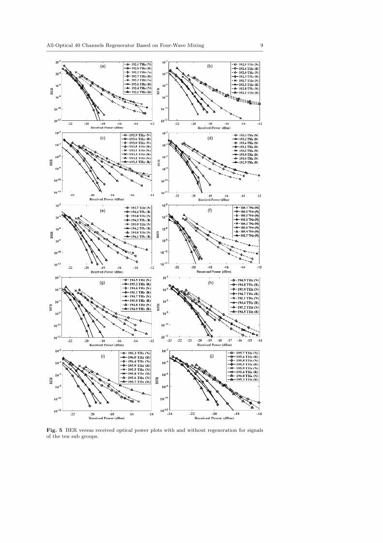
Fig. 5 shows the complete set of BER values at different received opti-cal powers for the ten subgroups mentioned previously. For each subgroup,the BER curves of the four channels before and after regeneration have been
All-Optical 40 Channels Regenerator Based on Four-Wave Mixing 9
(a) (b)
(c) (d)
(e) (f)
(g) (h)
(i) (j)
Fig. 5 BER versus received optical power plots with and without regeneration for signalsof the ten sub groups.
10Please give a shorter version with: \authorrunning and \titlerunning prior to \maketitle
Table 1 Receiver sensitivity values of the 40 channels before and after regeneration.
shown. It may be observed from the BER plots that the proposed regenerationscheme significantly improves the BER of the 40 channel WDM signal. It isworth mentioning here that the BERs were obtained by choosing a suitableoptical power for each sub-group that is input to the regenerator. As discussedin [20], for low input signal powers, the power of the sidebands at the outputof the HNLF remains very low. Therefore, the intensity of noise appearingon the zeros in the data stream is strongly compressed at the output of the
All-Optical 40 Channels Regenerator Based on Four-Wave Mixing 11
regenerator. After crossing a certain value of input power, the output powersuddenly increases and reaches a maximum point. This behaviour is similar tothat of a nonlinear switch. After the output power reaches a maximum point,further increasing the input power does not result in a significant increase inthe output power of a particular sideband. At this point, maximum compres-sion of intensity fluctuations on ones in the data stream is obtained. Based onthis behaviour of the generated sidebands, we have chosen a suitable operatingpoint for each sub-group by adjusting the gain of the amplifier placed afterthe 4x1 multiplexer in Fig. 2. This operating point is close to the point ofmaximum output power and results in the lowest BER.
5 Conclusion
We reported an all-optical multi-channel regeneration scheme for WDM sys-tems. A forty channel WDM signal was generated and passed through a stan-dard SMF to induce dispersion and nonlinear effects over the channels. Toreduce the OSNRs of the channels to 15 dB at the regenerator, broadbandnoise source was coupled with the WDM signal before transmission over theSMF. The forty channels were divided into five groups, each composed ofeight channels. A single CW pump laser source and two segments of HNLFswere used to regenerate all the eight channels in a single group. The proposedscheme is very useful for implementation in current WDM systems that areusing a single regenerator for a single channel. The introduction of our pro-posed regeneration scheme to such WDM systems would result in significantreduction in component count and therefore, an increase in cost efficiency. Anaverage improvement in receiver sensitivity of 4.246 dB, 3.935 dB, 3.72 dB,2.71 dB and 2.593 dB was observed for the first, second, third, fourth andfifth group, respectively. The proposed scheme is scalable to higher data ratessince it is based upon ultra-fast nonlinear interaction inside HNLFs.
6 Declarations
Funding
Not Applicable
Conflicts of interest/Competing interests
On behalf of all authors, the corresponding author states that there is noconflict of interest.
Availability of data and material
Available on request.
12Please give a shorter version with: \authorrunning and \titlerunning prior to \maketitle
Code Availability
Available on request.
References
1. Samael Sarmiento, Jose A. Altabas, Salvatore Spadaro, Jose A. Lazaro, “Experimentalassessment of 10 Gbps 5G multicarrier waveforms for high-layer split U-DWDM-PON-based fronthaul,” Journal of Lightwave Technol., vol. 37, no. 10, pp. 2344–2351, May2019, doi: 10.1109/JLT.2019.2904114.
2. Alsulami, Mashael and Akkari, “The role of 5G wireless networks in the internet-of-things (IoT),” International Conference on Computer Applications & Information Se-curity (ICCAIS), pp. 1–8, Dec. 2018, doi: 10.14419/ijet.v7i1.5.9155.
3. Matteo Fiorani, Paolo Monti, Bjorn Skubic, Jonas Martensson, Luca Valcarenghi, PieroCastoldi, Lena Wosinska, “Challenges for 5G transport networks,” IEEE InternationalConference on Advanced Networks and Telecommuncations Systems (ANTS), pp. 1-6,Dec. 2014, doi: 10.1109/ants.2014.7057286.
4. Peter Ohlen, Bjorn Skubic, Zere Ghebretensae, Wolfgang John, Meral Shirazipour,“Software-defined networking in a multi-purpose DWDM-centric metro/aggregationnetwork,” IEEE Globecom Workshops, pp. 1233-1238, Dec. 2013, doi: 10.1109/glo-comw.2013.6825162.
5. A. D. Ellis, M. E. McCarthy, M. A. Z. Al-Khateeb, and S. Sygletos, “Capacity limitsof systems employing multiple optical phase conjugators,” Opt. express, vol. 23, no. 16,pp. 20381–20393, Aug. 2015, doi: 10.1364/oe.23.020381.
6. E. Ciaramella, F. Curti and S. Trillo, “All-optical signal reshaping by means of four-wave mixing in optical fibers,” in IEEE Photonics Technol., vol. 13, no. 2, pp. 142-144,Feb. 2001, doi: 10.1109/68.910515.
7. Francesca Parmigiani, Lionel Provost, Periklis Petropoulos, David J. Richardson, Wolf-gang Freude, Juerg Leuthold, Andrew D. Ellis, Ioannis Tomkos, “Progress in Multi-channel All-Optical Regeneration Based on Fiber Technology,” IEEE Journal of Se-lected Topics in Quantum Electronics, vol. 18, no. 2, pp. 689-700, Mar. 2012, doi:10.1109/jstqe.2011.2126040.
8. B. Guo, F. Wen, B. Wu, F. Sun and K. Qiu, “All-Optical Multilevel Amplitude Regen-eration Based on Polarization-Orthogonal Continuous-Wave-Light-Assisted Nonlinear-Optical Loop Mirror (PC-NOLM) Subsystem,” in IEEE Access, vol. 7, pp. 149666-149671, Oct. 2019, doi: 10.1109/access.2019.2947303.
9. Sygletos, Frascella, Gunning, F.C.G. and Ellis, “Multi-wavelength regeneration of phaseencoded signals based on phase sensitive amplifiers,” ICTON, pp. 1–4, Jul. 2012, doi:10.1109/icton.2012.6253868.
10. Leclerc, Olivier, “Optical vs. Electronic in-line Signal Processing in Optical Communi-cation Systems: An exciting challenge for Optical Devices,” Signal, vol. 1, pp. 0, Jan.2003.
11. Jeyran Amirloo, Mohsen Razavi, A. Hamed Majedi, “Quantum key distribution overprobabilistic quantum repeaters,” Physical Review A, vol. 82, no. 3, pp. 032304, Sep.2010, doi: 10.1103/physreva.82.032304.
12. Francesca Parmigiani, Symeon Asimakis, Naoki Sugimoto, Fumihito Koizumi, PeriklisPetropoulos, and David J. Richardson, “2R regenerator based on a 2-m-long highlynonlinear bismuth oxide fiber,” Optics express, vol. 14, no.12, pp. 5038–5044, 2006, doi:10.1364/oe.14.005038.
13. Laurent Bramerie, Quang Trung Le, Mathilde Gay, Arthur OHare, Sebastien Lobo,Michel Joindot, Jean-Claude Simon, Hoang-Trung Nguyen, Jean-Louis Oudar, “All-optical 2R regeneration with a vertical microcavity-based saturable absorber,” IEEEJournal of Selected Topics in Quantum Electronics, vol. 18, no. 2, pp. 870–883, Mar.2012, doi: 10.1109/jstqe.2011.2125779.
14. Martin Rochette, Justin L. Blows, and Benjamin J. Eggleton, “3R optical regeneration:An all-optical solution with BER improvement,” Opt. Express, vol. 14, no. 14, pp.6414–6427, June 2006, doi: 10.1364/oe.14.006414.
All-Optical 40 Channels Regenerator Based on Four-Wave Mixing 13
15. Kevin Croussore and Guifang Li, “Phase regeneration of NRZ-DPSK signals based onsymmetric-pump phase-sensitive amplification,” IEEE Photonics Technol. Letters, vol.19, no. 11, pp. 864–866, June 2007, doi: 10.1109/lpt.2007.897501.
16. Hongxiang Wang, Tiantian Luo, and Yuefeng Ji, “Multi-channel phase regeneration ofQPSK signals based on phase sensitive amplification,” Frontiers of Optoelectronics, vol.12, no. 1, pp. 24–30, Mar. 2019, doi: 10.1007/s12200-018-0754-8.
17. Ju Wang, Hua Ji, Hao Hu, Jinlong Yu, Hans Christian Hansen Mulvad, Michael Galili,Palle Jeppesen, and Leif Katsuo Oxenlowe, “4× 160-Gbit/s multi-channel regenerationin a single fibre,” Optics express, vol. 22, no. 10, pp. 11456–11464, May 2014, doi:10.1364/oe.22.011456.
18. Giampiero Contestabile, Marco Presi, Ernesto Ciaramella, “All-optical regeneration of40 Gb/s constant envelope alternative modulation formats,” IEEE journal of quantumelectronics, vol. 46, no. 3, pp. 340–346, Mar. 2010, doi: 10.1109/jqe.2009.2033017.
19. Lu Li, Pallavi G. Patki, Young B. Kwon, Veronika Stelmakh, Brandon D. Campbell,Muthiah Annamalai, Taras I. Lakoba and Michael Vasilyev, “All-optical regeneratorof multi-channel signals,” Nature commun., vol. 8, no. 1, pp. 1-11, Dec. 2017, doi:10.1038/s41467-017-00874-0.
20. E. Ciaramella and S. Trillo, ”All-optical signal reshaping via four-wave mixing in opticalfibers,” in IEEE Photonics Technology Letters, vol. 12, no. 7, pp. 849-851, July 2000,doi: 10.1109/68.853523.
Figures
Figure 1
A CW pump and a pulsed signal are passed through a dispersion shifted HNLF to generate multiplesidebands by employing FWM.
Spectral plots of the �rst sub-group of Group 1 that has a frequency range of 192.1 T Hz to 192.4 T Hz(a) Before addition of broadband noise, (b) After addition of broadband noise and transmission over 40km SMF, (c) At the output of the HNLF after FWM.
Figure 4
Eye diagram of Channel 1 at (a) the input of the regenerator, (b) output of the regenerator.
Figure 5
BER versus received optical power plots with and without regeneration for signals of the ten sub groups


![Research Article Uncertainty Analysis of Mixing …downloads.hindawi.com/journals/mse/2015/343087.pdfserpentine elements [, ], two-layered crossing channels [, ], and microchannels](https://static.documents.pub/doc/80x56/5f952e9653c95b217f3957c3/research-article-uncertainty-analysis-of-mixing-serpentine-elements-two-layered.jpg)

