1 WC3.2 Matsumoto / 27 M. Matsumoto Graduate School of Engineering Osaka University 2010 IEEE Photonics Society Summer Topical Meeting on Nonlinear Fiber Optics July 19-21, 2010 All-Optical Regeneration of Phase-Encoded Signals in Transmission Systems
Transcript
1WC3.2 Matsumoto / 27
M. Matsumoto
Graduate School of EngineeringOsaka University
2010 IEEE Photonics Society Summer Topical Meetingon Nonlinear Fiber Optics
July 19-21, 2010
All-Optical Regeneration of Phase-EncodedSignals in Transmission Systems
2WC3.2 Matsumoto / 27
Outline
◆ Introduction
◆ Summary
◆ (D)BPSK signal regeneration
◆ (D)QPSK signal regeneration
◆ Discussion
3WC3.2 Matsumoto / 27
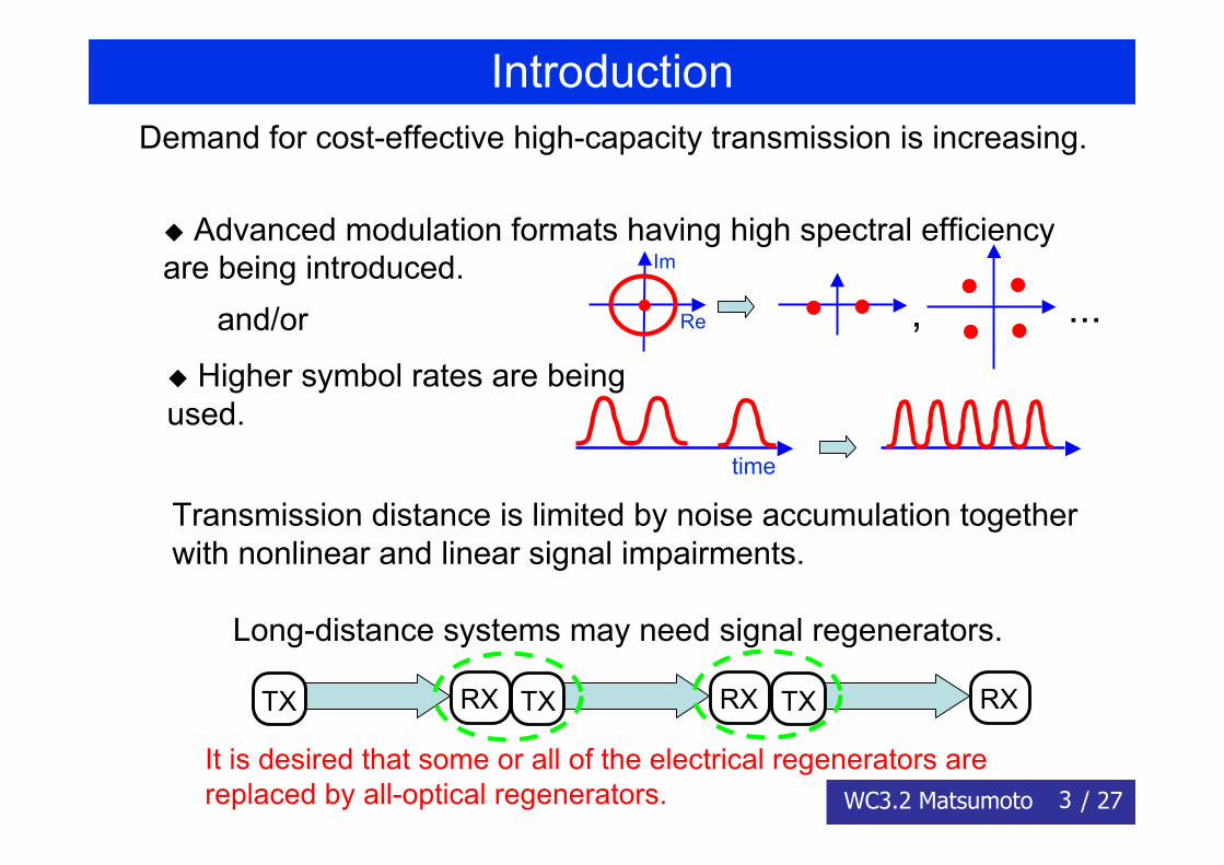
Introduction Demand for cost-effective high-capacity transmission is increasing.
◆ Higher symbol rates are beingused.
◆ Advanced modulation formats having high spectral efficiencyare being introduced.
and/or , ...
time
Re
Im
Transmission distance is limited by noise accumulation togetherwith nonlinear and linear signal impairments.
Long-distance systems may need signal regenerators.
TX RX TX RX TX RX
It is desired that some or all of the electrical regenerators arereplaced by all-optical regenerators.
4WC3.2 Matsumoto / 27
Introduction
Issues
All-optical regenerators
higher-speed operation lower-power consumption less format-dependent operation
are expected.
◆ Regeneration of signals in advanced modulation formats(QPSK, 8PSK, QAM,....) is yet to be explored.
◆ Regenerators accept only signals meeting predeterminedconditions (pulse width, chirp,...).
◆ DEMUX/MUX are needed in general for regeneration ofWDM signals.
5WC3.2 Matsumoto / 27
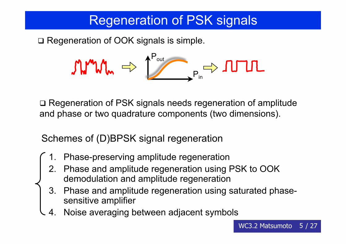
Regeneration of PSK signals
Regeneration of PSK signals needs regeneration of amplitudeand phase or two quadrature components (two dimensions).
Regeneration of OOK signals is simple.
Pout
Pin
1. Phase-preserving amplitude regeneration2. Phase and amplitude regeneration using PSK to OOK
demodulation and amplitude regeneration3. Phase and amplitude regeneration using saturated phase-
sensitive amplifier4. Noise averaging between adjacent symbols
Schemes of (D)BPSK signal regeneration
6WC3.2 Matsumoto / 27
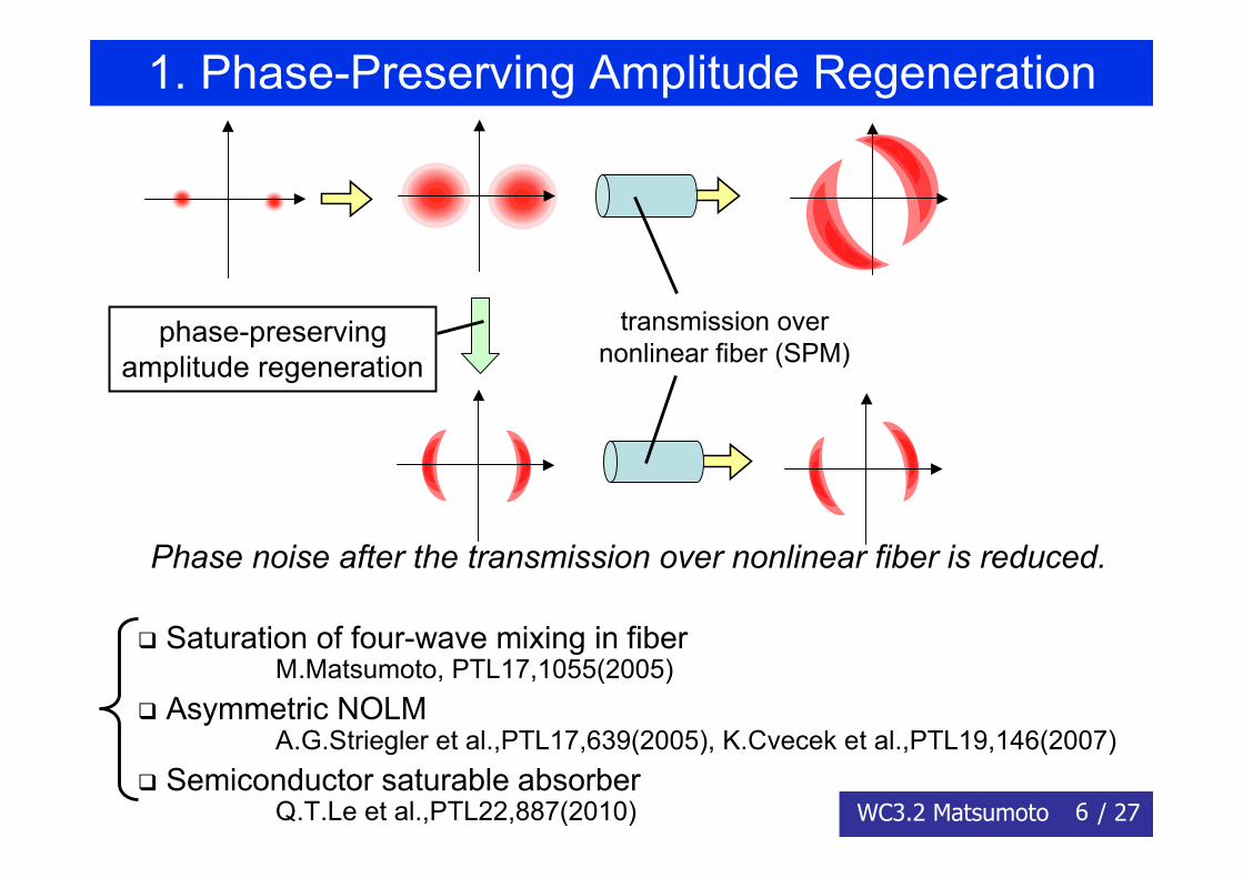
1. Phase-Preserving Amplitude Regeneration
phase-preservingamplitude regeneration
transmission overnonlinear fiber (SPM)
Phase noise after the transmission over nonlinear fiber is reduced.
Saturation of four-wave mixing in fiber M.Matsumoto, PTL17,1055(2005) Asymmetric NOLM A.G.Striegler et al.,PTL17,639(2005), K.Cvecek et al.,PTL19,146(2007) Semiconductor saturable absorber Q.T.Le et al.,PTL22,887(2010)
7WC3.2 Matsumoto / 27
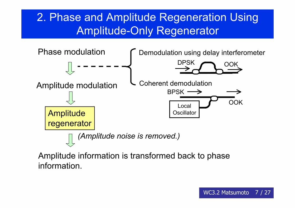
2. Phase and Amplitude Regeneration UsingAmplitude-Only Regenerator
Phase modulation
Amplitude modulation
Amplituderegenerator
Amplitude information is transformed back to phaseinformation.
Demodulation using delay interferometer
Coherent demodulation
(Amplitude noise is removed.)
DPSK OOK
BPSK
OOKLocalOscillator
8WC3.2 Matsumoto / 27
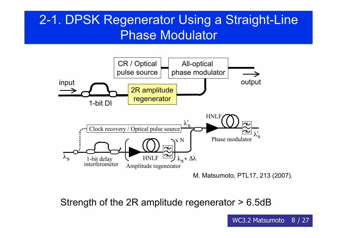
2-1. DPSK Regenerator Using a Straight-LinePhase Modulator
2R amplituderegenerator
All-optical phase modulator
input output
1-bit DI
CR / Opticalpulse source
λs λs+ Δλ
Clock recovery / Optical pulse source
1-bit delayinterferometer
x N
λ'sλ's
HNLF
HNLF
Phase modulator
Amplitude regenerator
Strength of the 2R amplitude regenerator > 6.5dB
M. Matsumoto, PTL17, 213 (2007).
9WC3.2 Matsumoto / 27
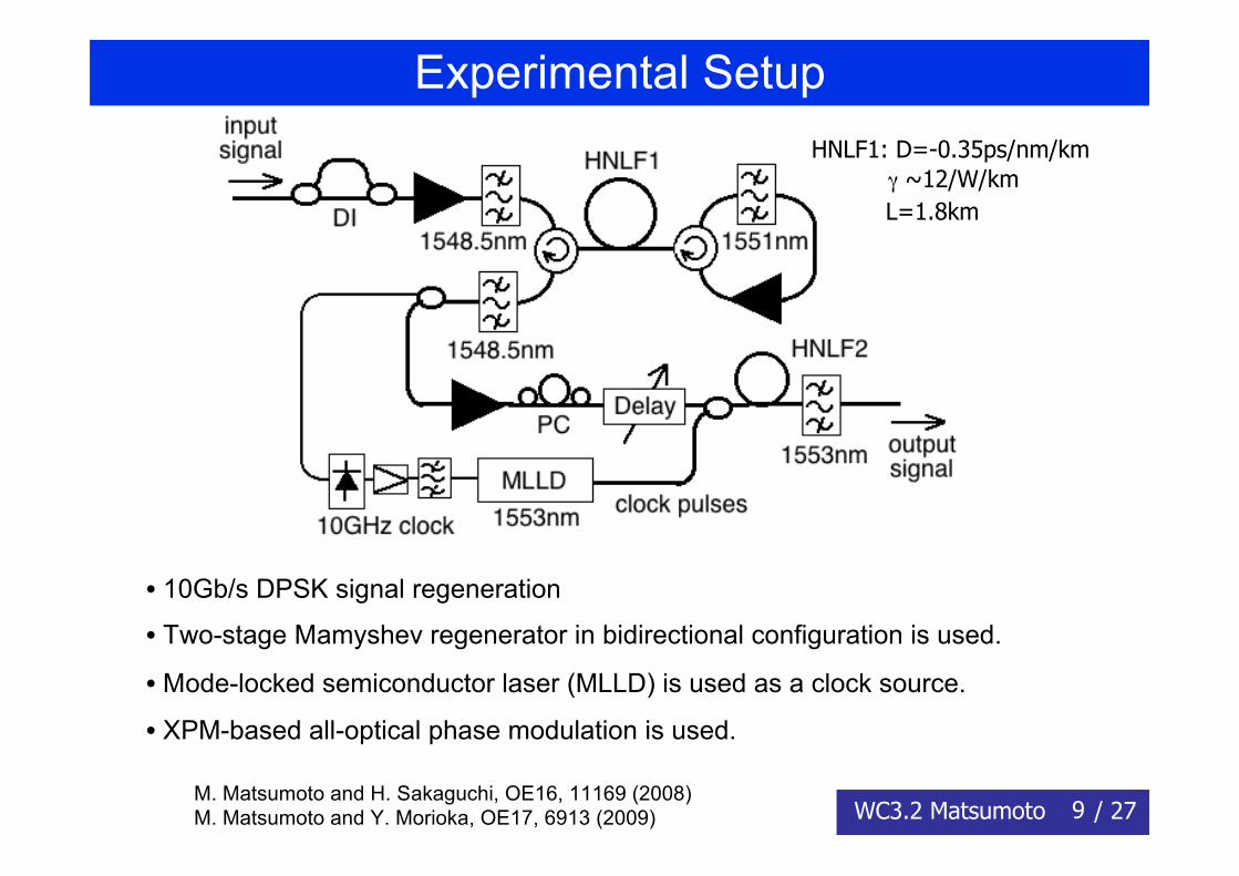
Experimental Setup
• 10Gb/s DPSK signal regeneration
• Two-stage Mamyshev regenerator in bidirectional configuration is used.
• Mode-locked semiconductor laser (MLLD) is used as a clock source.
• XPM-based all-optical phase modulation is used.
HNLF1: D=-0.35ps/nm/km γ ~12/W/km L=1.8km
M. Matsumoto and H. Sakaguchi, OE16, 11169 (2008)M. Matsumoto and Y. Morioka, OE17, 6913 (2009)
10WC3.2 Matsumoto / 27
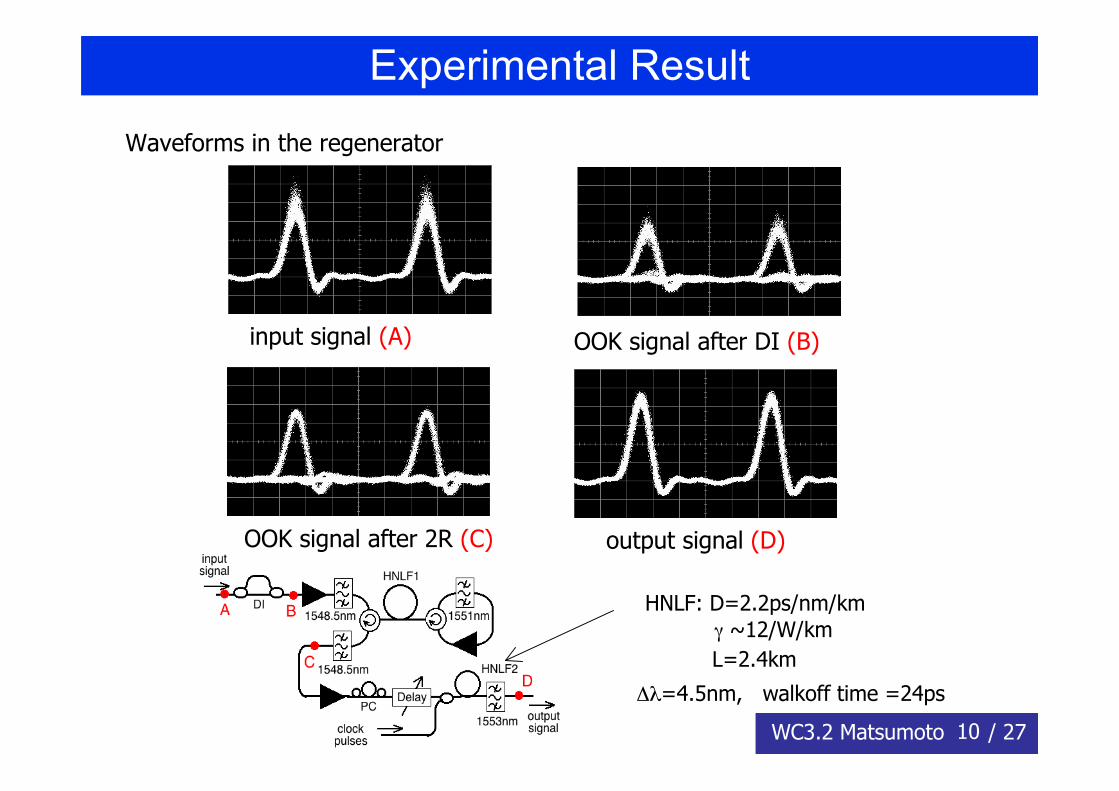
Experimental Result
Waveforms in the regenerator
input signal (A) OOK signal after DI (B)
OOK signal after 2R (C) output signal (D)
HNLF: D=2.2ps/nm/km γ ~12/W/km L=2.4km
Δλ=4.5nm, walkoff time =24ps
11WC3.2 Matsumoto / 27
Transmission Experiment
DPSKTX
DPSK signalregenerator
DPSKRXATT1
DDM fiber (DSF) 40km SMF (50km)+DCF
Ps
ATT2
Transmission experiment at 10Gb/s
Signal before the regenerator is degraded either by nonlinearity(when Ps is large) or by ASE (when ATT1 is large).
12WC3.2 Matsumoto / 27
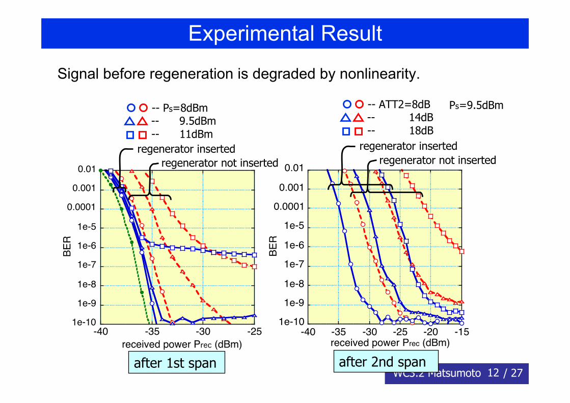
Experimental Result
Signal before regeneration is degraded by nonlinearity.
1e-10
1e-9
1e-8
1e-7
1e-6
1e-5
0.0001
0.001
0.01
-40 -35 -30 -25 -20 -15
BE
R
received power Prec (dBm)
after 2nd span
1e-10
1e-9
1e-8
1e-7
1e-6
1e-5
0.0001
0.001
0.01
-40 -35 -30 -25
BE
R
received power Prec (dBm)
after 1st span
regenerator not insertedregenerator inserted
-- Ps=8dBm-- 9.5dBm-- 11dBm
regenerator not insertedregenerator inserted
-- ATT2=8dB-- 14dB-- 18dB
Ps=9.5dBm
13WC3.2 Matsumoto / 27
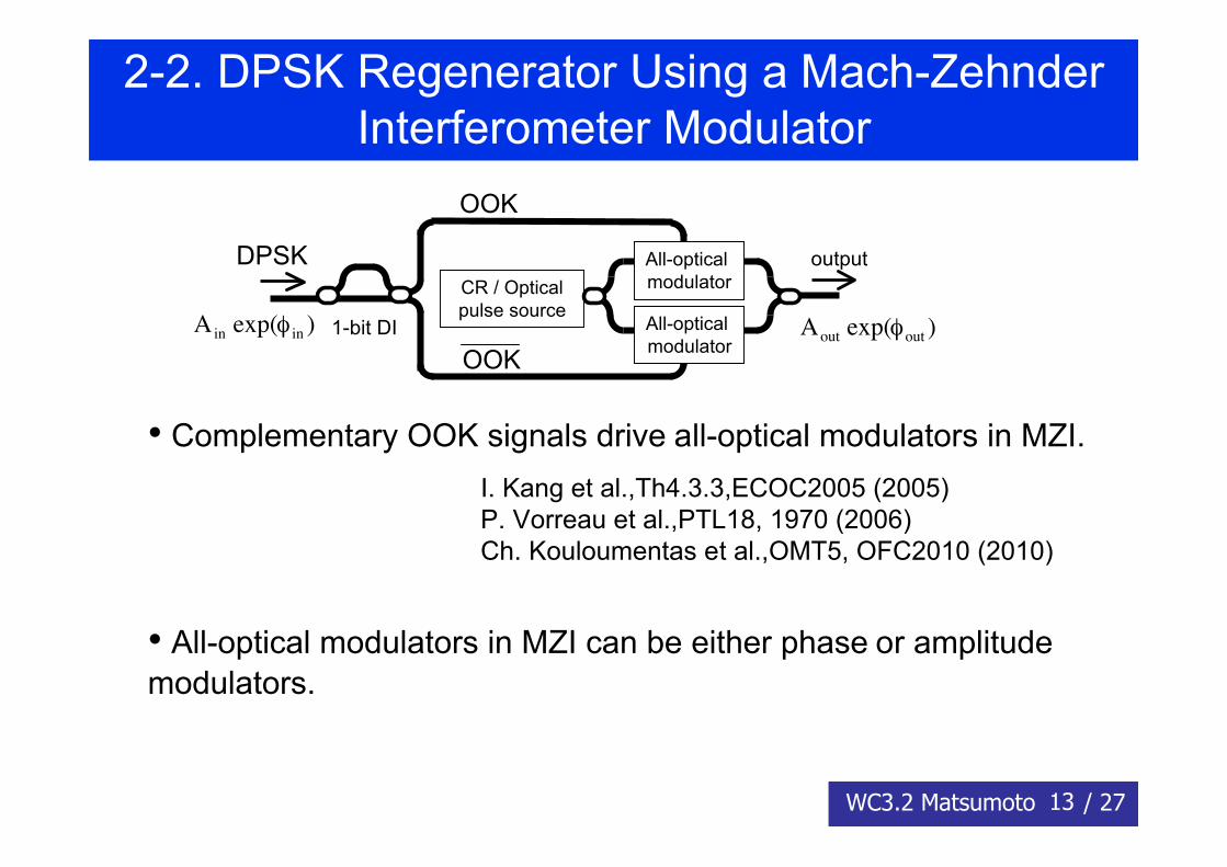
2-2. DPSK Regenerator Using a Mach-ZehnderInterferometer Modulator
• Complementary OOK signals drive all-optical modulators in MZI.
• All-optical modulators in MZI can be either phase or amplitudemodulators.
outputCR / Opticalpulse source
All-optical modulator
All-optical modulator
1-bit DI
DPSK
OOK
OOK
!
Ain exp(" in )
!
Aout exp("out )
I. Kang et al.,Th4.3.3,ECOC2005 (2005)P. Vorreau et al.,PTL18, 1970 (2006)Ch. Kouloumentas et al.,OMT5, OFC2010 (2010)
14WC3.2 Matsumoto / 27
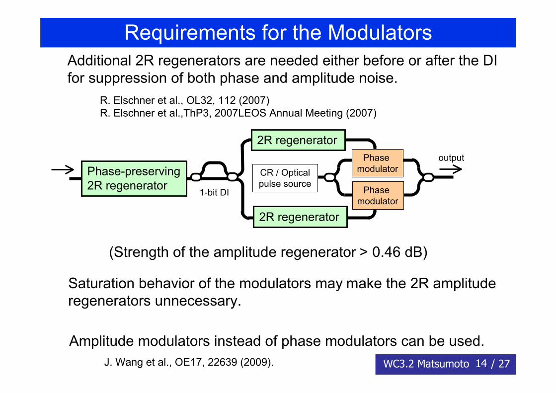
Requirements for the ModulatorsAdditional 2R regenerators are needed either before or after the DIfor suppression of both phase and amplitude noise.
outputCR / Opticalpulse source
Phase modulator
Phase modulator
1-bit DI
Phase-preserving2R regenerator
2R regenerator
2R regenerator
(Strength of the amplitude regenerator > 0.46 dB)
Amplitude modulators instead of phase modulators can be used.
Saturation behavior of the modulators may make the 2R amplituderegenerators unnecessary.
R. Elschner et al., OL32, 112 (2007)R. Elschner et al.,ThP3, 2007LEOS Annual Meeting (2007)
J. Wang et al., OE17, 22639 (2009).
15WC3.2 Matsumoto / 27
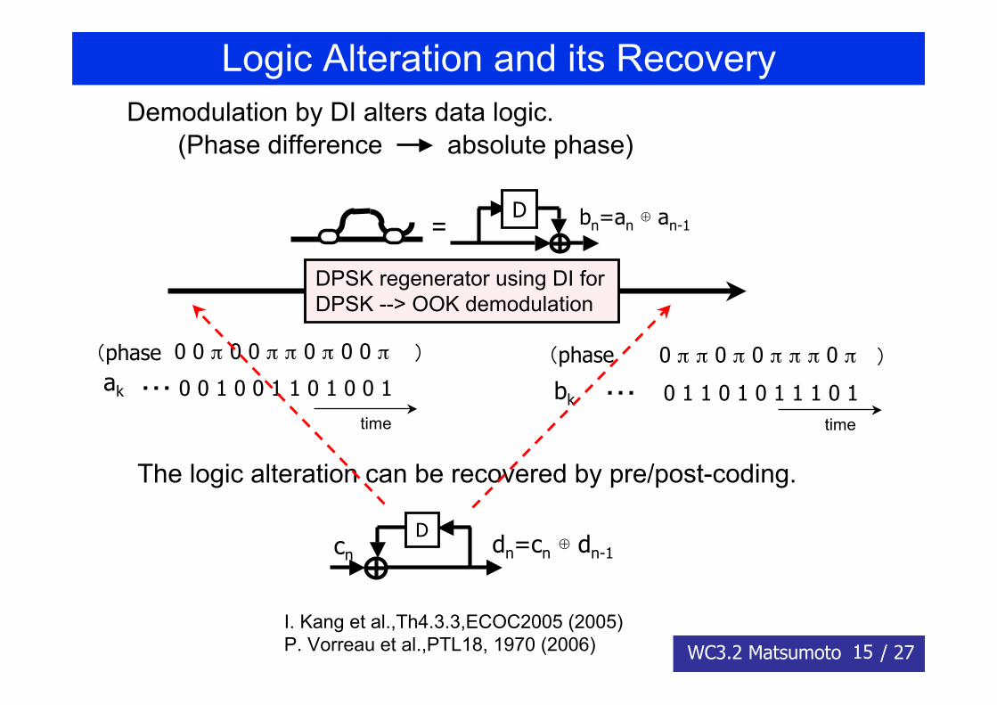
Logic Alteration and its Recovery
Dcn dn=cn ⊕ dn-1
DPSK regenerator using DI forDPSK --> OOK demodulation
bn=an ⊕ an-1D
=
bk ・・・ 0 1 1 0 1 0 1 1 1 0 1
0 π π 0 π 0 π π π 0 π(phase )(phase
time
ak ・・・ 0 0 1 0 0 1 1 0 1 0 0 1
0 0 π 0 0 π π 0 π 0 0 π )
time
Demodulation by DI alters data logic.(Phase difference absolute phase)
The logic alteration can be recovered by pre/post-coding.
I. Kang et al.,Th4.3.3,ECOC2005 (2005)P. Vorreau et al.,PTL18, 1970 (2006)
16WC3.2 Matsumoto / 27
2-3. BPSK Regenerator Using Coherent DemodulationDemodulation from DPSK to OOK by DI may be replaced bycoherent demodulation.
2R
phasemodulator
input output
CR / Opticalpulse source
Localoscillator
Coherent demodulation can be similarlyused in the MZI-based regenerator.
Required strength of 2R may be halved.Logic of the signal is preserved.◆ Phase-locked local oscillator is needed.
1-bit DI2R
phasemodulator
input output
CR / Opticalpulse source
17WC3.2 Matsumoto / 27
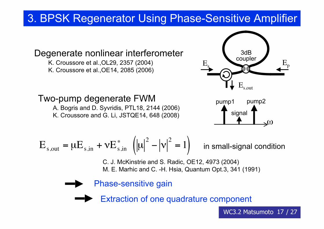
3. BPSK Regenerator Using Phase-Sensitive Amplifier
Degenerate nonlinear interferometer
Two-pump degenerate FWM
3dBcouplerEs Ep
Es,out
signal
pump1 pump2
ω
!
Es,out
= µEs,in
+ "Es,in
#
!
µ2
" #2
= 1( )
Phase-sensitive gain
in small-signal condition
Extraction of one quadrature component
K. Croussore et al.,OL29, 2357 (2004)K. Croussore et al.,OE14, 2085 (2006)
A. Bogris and D. Syvridis, PTL18, 2144 (2006)K. Croussore and G. Li, JSTQE14, 648 (2008)
C. J. McKinstrie and S. Radic, OE12, 4973 (2004)M. E. Marhic and C. -H. Hsia, Quantum Opt.3, 341 (1991)
18WC3.2 Matsumoto / 27
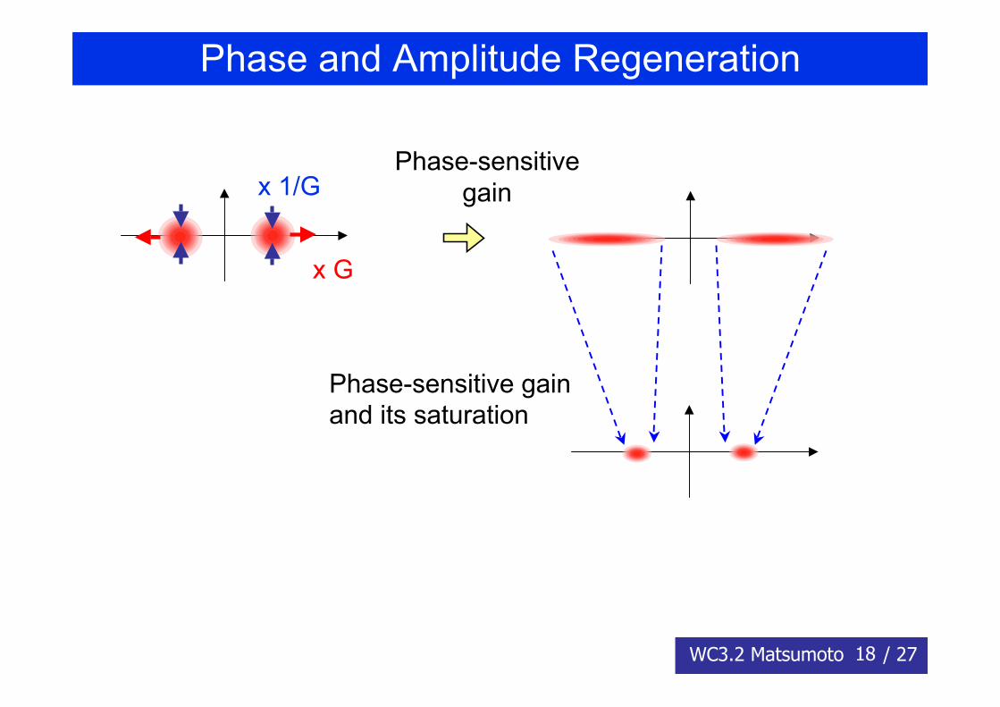
Phase and Amplitude Regeneration
x G
x 1/GPhase-sensitive
gain
Phase-sensitive gainand its saturation
19WC3.2 Matsumoto / 27
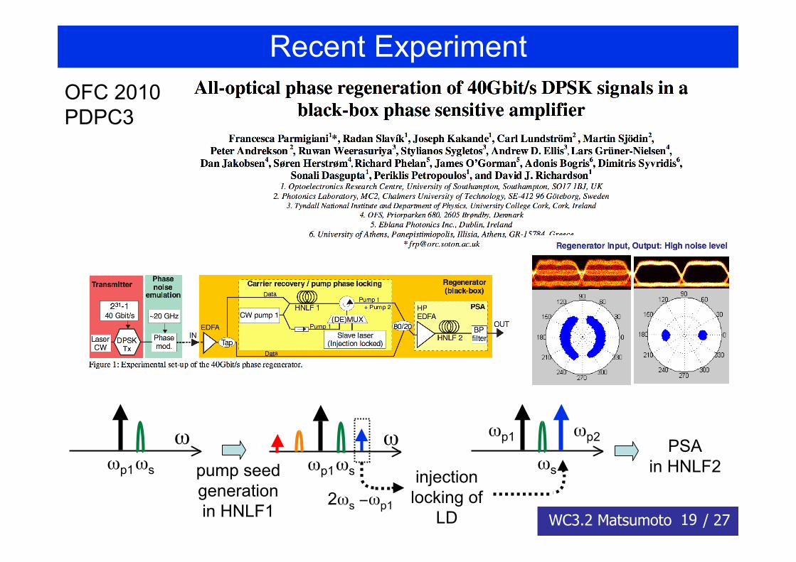
Recent ExperimentOFC 2010PDPC3
ωp1ωs
ω
2ωs −ωp1
ωp1ωs
ωpump seedgenerationin HNLF1
injectionlocking of
LD
ωp1
ωs
ωp2 PSAin HNLF2
20WC3.2 Matsumoto / 27
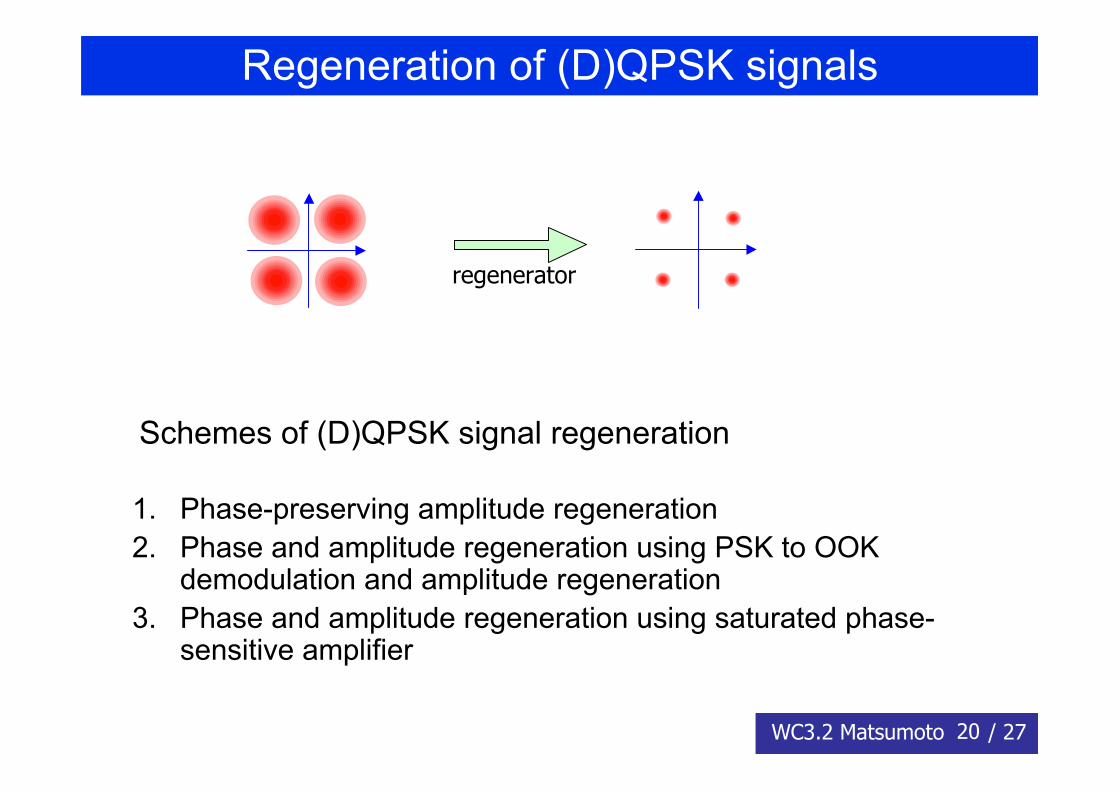
Regeneration of (D)QPSK signals
1. Phase-preserving amplitude regeneration2. Phase and amplitude regeneration using PSK to OOK
demodulation and amplitude regeneration3. Phase and amplitude regeneration using saturated phase-
sensitive amplifier
Schemes of (D)QPSK signal regeneration
regenerator
21WC3.2 Matsumoto / 27
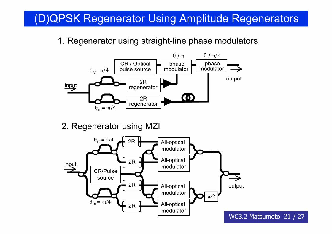
(D)QPSK Regenerator Using Amplitude Regenerators
1. Regenerator using straight-line phase modulators
2. Regenerator using MZI
2Rregeneratorinput
output
phasemodulator
0 / π 0 / π/2
CR / Opticalpulse sourceθDI=π/4
θDI=-π/4
2Rregenerator
phasemodulator
input
output
CR/Pulsesource
All-optical modulator
All-optical modulator
All-optical modulator
All-optical modulator
2R
2R
2R
2R
θDI = π/4
θDI = -π/4π/2
22WC3.2 Matsumoto / 27
(D)QPSK Regenerator Using Amplitude Regenerators
• Required strength of 2R amplitude regenerators is larger thanthat of DPSK regenerators.
Delay interferometers (DIs) are not operated at their maximain output power vs phase difference response.
Suppression of input phase noise is weaker.
• Logic alteration can be recovered by suitable pre/post coding atterminals.
• Coherent demodulation instead of DI demodulation can beused. (X. Yi et al., JLT28,587 (2010))
23WC3.2 Matsumoto / 27
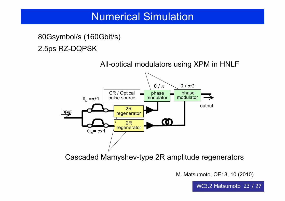
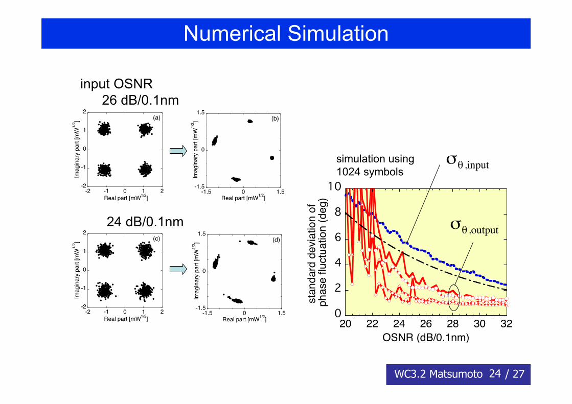
Numerical Simulation
2Rregeneratorinput
output
phasemodulator
0 / π 0 / π/2
CR / Opticalpulse sourceθDI=π/4
θDI=-π/4
2Rregenerator
phasemodulator
All-optical modulators using XPM in HNLF
Cascaded Mamyshev-type 2R amplitude regenerators
80Gsymbol/s (160Gbit/s)2.5ps RZ-DQPSK
M. Matsumoto, OE18, 10 (2010)
24WC3.2 Matsumoto / 27
Numerical Simulation
-2
-1
0
1
2
-2 -1 0 1 2
Ima
gin
ary
pa
rt [
mW
1/2
]
Real part [mW1/2
]
(a)
-1.5
0
1.5
-1.5 0 1.5Im
ag
ina
ry p
art
[m
W1
/2]
Real part [mW1/2
]
(b)
-2
-1
0
1
2
-2 -1 0 1 2
Ima
gin
ary
pa
rt [
mW
1/2
]
Real part [mW1/2
]
(c)
-1.5
0
1.5
-1.5 0 1.5
Ima
gin
ary
pa
rt [
mW
1/2
]
Real part [mW1/2
]
(d)
input OSNR26 dB/0.1nm
24 dB/0.1nm
0
2
4
6
8
10
20 22 24 26 28 30 32sta
nd
ard
de
via
tio
n o
f p
ha
se
flu
ctu
atio
n (
de
g)
OSNR (dB/0.1nm)
!
"# ,input
!
"# ,output
simulation using1024 symbols
25WC3.2 Matsumoto / 27
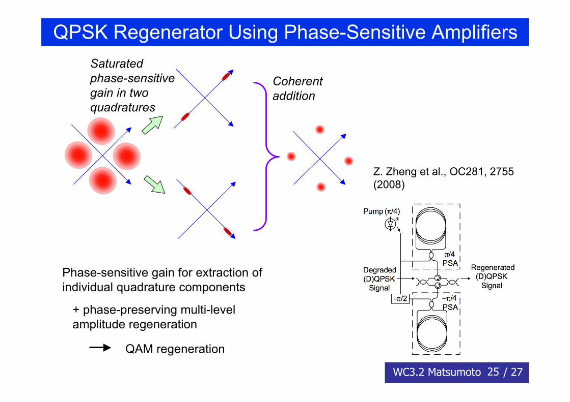
QPSK Regenerator Using Phase-Sensitive AmplifiersSaturatedphase-sensitivegain in twoquadratures
Coherentaddition
Z. Zheng et al., OC281, 2755(2008)
Phase-sensitive gain for extraction ofindividual quadrature components
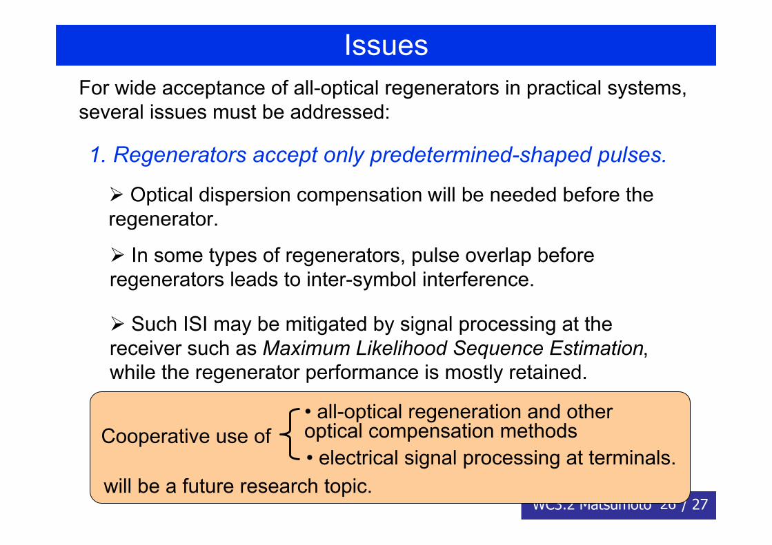
1. Regenerators accept only predetermined-shaped pulses.
For wide acceptance of all-optical regenerators in practical systems,several issues must be addressed:
Optical dispersion compensation will be needed before theregenerator.
In some types of regenerators, pulse overlap beforeregenerators leads to inter-symbol interference.
Such ISI may be mitigated by signal processing at thereceiver such as Maximum Likelihood Sequence Estimation,while the regenerator performance is mostly retained.
Cooperative use of• all-optical regeneration and otheroptical compensation methods• electrical signal processing at terminals.
will be a future research topic.
27WC3.2 Matsumoto / 27
SummaryRegeneration of phase-encoded signals has been discussed.
1. (D)BPSK-signal regeneration•Phase-preserving amplitude regenerator•Phase and amplitude regenerator using (D)BPSK to OOKdemodulation•Phase and amplitude regenerator using phase-sensitiveamplifier
2. (D)QPSK-signal regeneration•Simulation of 160Gb/s DQPSK signal regeneration usingfiber-based amplitude regenerator.
3. Issues in using all-optical regenerators in real systems