188
AL Manager Application of the NMS5UX or NMS5LX system for the management of AL (Access Link) equipment User manual MN.00108.E - 003 Volume 1/1
| Date post: | 24-Oct-2014 |
| Category: |
Documents |
| Upload: | cprietomunoz |
| View: | 96 times |
| Download: | 1 times |

AL ManagerApplication of the NMS5UX or NMS5LXsystem for the management of AL(Access Link) equipment
User manual
MN.00108.E - 003Volume 1/1

The information contained in this handbook is subject to change without notice.
Property of Siae Microelettronica S.p.A. All rights reserved according to the law and according to the inter-national regulations. No part of this document may be reproduced or transmitted in any form or by anymeans, electronic or mechanical, without written permission from Siae Microelettronica S.p.A.
Unless otherwise specified, reference to a Company, name, data and address produced on the screen di-splayed is purely indicative aiming at illustrating the use of the product.
MS-DOS®, MS Windows® are trademarks of Microsoft Corporation
HP®, HP OpenView NNM and HP–UX are Hewlett Packard Company registered trademarks.
UNIX is a UNIX System Laboratories registered trademark.
Oracle® is a Oracle Corporation registered trademark.
Linux term is a trademark registered by Linus Torvalds, the original author of the Linux operating system.Linux is freely distributed according the GNU General Public License (GPL).
Other products cited here in are constructor registered trademarks.
AL Manager - MN.00108.E - 003 1
AL ManagerCONTENTS
Section 1.AL MANAGER PROGRAM 9
1 RELEASE ..................................................................................................................10
2 FUNCTIONS..............................................................................................................11
Section 2.GRAPHICAL INTERFACE 13
3 RADIO PDH-AL: EQUIPMENT WINDOW ....................................................................14
3.1 Title bar ..........................................................................................................14
3.2 Menu bar.........................................................................................................15
3.3 Push-button bar ...............................................................................................15
3.4 Status bar .......................................................................................................16
3.5 Equipment view area.........................................................................................18
3.6 Equipment info area..........................................................................................19
4 RADIO PDH-AL: SUBRACK WINDOW ........................................................................21
5 RADIO PDH-AL: UNIT WINDOW ...............................................................................25
5.1 Set operation ...................................................................................................27
5.2 Get operation...................................................................................................27
5.3 Get and Set operations for the virtual equipment ..................................................28
Section 3.OPERATING PROCEDURES 29
6 OPENING/CLOSING OF THE RADIO PDH-AL: EQUIPMENT WINDOW ........................29
6.1 Opening of the Radio PDH-AL: Equipment window.................................................30

2 AL Manager - MN.00108.E - 003
6.1.1 Messages displayed at the window opening ...............................................30
6.1.2 Messages displayed when the window is open.............................................31
6.1.3 Updating of the information present into the window ...................................32
6.1.4 Opening of more Radio PDH-AL: Equipment windows...................................32
6.1.5 User profile (Superuser, Privileged, Advanced, etc.).....................................32
6.2 Closing of the Radio PDH-AL: Equipment window ..................................................32
6.2.1 Automatic closing of the window ...............................................................33
7 AL VIRTUAL EQUIPMENT..........................................................................................34
7.1 To configure an AL virtual equipment ..................................................................34
Section 4.MENUS, PUSH-BUTTONS AND CONTEXTUAL AREAS 37
8 FILE (MENU) ............................................................................................................37
8.1 File - Close ......................................................................................................37
8.2 File - Exit.........................................................................................................37
9 COMMANDS (MENU).................................................................................................39
9.1 Commands – Reset Equipment Controller.............................................................39
9.1.1 To reset the equipment............................................................................39
9.2 Commands – Alarm Re-alignment .......................................................................40
9.2.1 To force the equipment to forward its current alarms ...................................40
9.3 Commands – Line Test ......................................................................................40
9.3.1 To check the reach ability of the equipment................................................40
9.4 Commands – View/Modify PM Status ...................................................................40
9.5 Commands – Configuration Download .................................................................41
9.6 Commands – NE SW/FW Release ........................................................................41
9.7 Commands – Modify LCT Configuration Mode........................................................41
9.7.1 To enable the LCT user to be able to connect himself to the equipmentby means of the LCT program, in Configuration mode ..................................42
9.7.2 To disable the LCT user to be able to connect himself to the equipmentby means of the LCT program, in Configuration mode ..................................42
10 ALARMS (MENU) ......................................................................................................43
10.1 Alarms – Current Alarms ...................................................................................43
10.2 Alarms – Alarm History......................................................................................44
10.3 Alarms – Equipment Severity Code .....................................................................44
11 OPTIONS (MENU).....................................................................................................46
11.1 Options – View Active Manual Operation ..............................................................46
11.1.1 Check the manual operations actually activated ..........................................46
11.1.2 To set the manual operations timeout........................................................47
11.2 Options - LCT Logged Users ...............................................................................47
11.3 Options - LCT Equipment Users ..........................................................................48
11.4 Options – View Acknowledge Status ....................................................................48
11.4.1 To check the acknowledge status of the alarms, LCT presence andConfiguration Upload failed ......................................................................48

AL Manager - MN.00108.E - 003 3
12 MAINTENANCE (MENU)............................................................................................50
12.1 Maintenance - Radio Switch ...............................................................................50
12.1.1 To check/change the management of the switching in reception(Rx Forced Switch)..................................................................................50
12.1.2 To check/change the management of the switching in transmission(Tx Forced Switch)..................................................................................52
12.1.3 To check/change the management of the preferential branch in reception(Rx Preferential) .....................................................................................52
12.1.4 To check/change the management of the preferential branch in transmission(Tx Preferential) .....................................................................................53
12.1.5 To check/change the Wait Time parameter .................................................53
12.1.6 To force the switch on the preferential branch without waiting for theWait Time ..............................................................................................53
12.2 Maintenance - Radio Branch x Loop.....................................................................54
12.2.1 To verify/modify the status of loops...........................................................54
13 HELP (MENU) ...........................................................................................................56
13.1 Help – On Usage...............................................................................................56
14 PRBS (PUSH-BUTTON) .............................................................................................57
14.1 To verify the PRBS measure status......................................................................57
14.2 To activate/reset the PRBS measure....................................................................59
14.3 To deactivate the PRBS measure ........................................................................59
14.4 To verify/modify the type of PRBS pattern used for the measure .............................59
14.5 To verify/modify the signal used for the measure ..................................................60
15 USER INPUT (PUSH-BUTTON) ..................................................................................61
15.1 To check the user input status (local/remote) .......................................................61
15.2 To check/change the name of the user input (local/remote) ...................................62
15.3 To check/change the activated condition of the local user input...............................63
15.4 To enable/disable the UI (local/remote) alarm or the forwarding of the trapto the supervisory system and to define the seriousness level of an UI (local/remote)63
16 USER OUTPUT (PUSH-BUTTON)................................................................................65
16.1 To check the user output status..........................................................................65
16.2 To check/change the name of the user output ......................................................66
16.3 To check/change the functioning mode of the user output relay contacts..................67
16.4 To couple with the user output a signal (alarms or UI) ...........................................67
16.5 To enabled the forced activation of the relays contacts from operator ......................69
16.6 To force the activation of the relay contacts relevant to a user output......................69
16.7 To remove the force activation of the relay contacts relevant to a user output ..........70
16.8 To force the download of the default name of the user output.................................70
17 RADIO EQUIPMENT (PUSH-BUTTON) .......................................................................72
17.1 To verify/modify the protection type of the local equipment....................................73
17.2 To verify the base band type of the local equipment ..............................................73
17.3 To verify/modify the capacity of the local equipment .............................................73
17.4 To verify/modify the capacity of the local and remote equipment ............................74
17.5 To verify/modify the modulation of the local equipment .........................................74
17.6 To verify/modify the modulation of the local and remote equipment ........................75
17.7 To verify/modify the connection number of the local equipment ..............................75
17.8 To verify/modify the connection identificative number of the local andremote equipment ............................................................................................76
4 AL Manager - MN.00108.E - 003
17.9 To verify/modify the threshold of the signal at reception, under which therelated alarms are activated...............................................................................76
17.10 To verify/modify the LBER alarm threshold...........................................................76
17.11 To verify/modify the HBER alarm threshold ..........................................................77
17.12 To verify/modify the EWL alarm threshold............................................................77
17.13 To verify/modify the using of the HBER alarm as switching and AIS insertioncriterion at reception.........................................................................................77
17.14 To verify/modify the using of the LBER alarm as switching criterion .........................78
17.15 To verify/modify the using of the EWL alarm as switching criterion ..........................78
17.16 To verify/modify the using of the number of errors detected by FEC asswitching criterion in reception ...........................................................................79
17.17 To verify/modify the insertion of the AIS signal at the receive side ..........................79
17.18 To verify/modify the enabling of the squelch on the services...................................80
17.19 To verify the type of interface of the “remote” port for the connection to theremote terminals ..............................................................................................80
17.20 To verify/modify the tributary used for the connection to the remoteterminal/tributary used for the PM measures ........................................................80
17.21 To verify/modify the number of the timeslot used for the connection to theremote terminal ...............................................................................................81
17.22 To verify/modify the 16Kbit used for the connection to the remote terminal..............81
17.23 To display/modify the resolution of the received power (Prx) ..................................82
17.24 To display/modify the resolution of the transmitted power (Ptx)..............................82
17.25 To display/modify the enabling of the switch in transmission ..................................82
17.26 To display/modify the T and N parameters ...........................................................83
17.27 To reset the Transmitter Switch on Remote Rx Alarm that notifies the switchin transmission.................................................................................................83
18 PERFORMANCE MONITORING (PUSH-BUTTON)........................................................84
18.1 To verify the status of the PM measurements and the relevant alarmsconcerning the threshold exceeding ....................................................................84
18.1.1 Quality parameters description (PM) ..........................................................86
18.2 To activate/deactivate the PM measurements .......................................................86
18.3 To set the thresholds of the control parameters and the intervention onesof the alarms (PM)............................................................................................87
18.4 To set the thresholds of the Rx and Tx power level (PM) ........................................88
18.5 To reset of the alarms concerning the threshold exceeding (PM) .............................89
18.6 To reset the values concerning the control parameters (PM) ...................................89
19 EQ. EAST - EQ. WEST (PUSH-BUTTONS) ...................................................................90
19.1 To verify/modify the capacity of the specific branch - local equipment......................90
19.2 To verify/modify the capacity of the specific branch - local and remote equipment.....91
19.3 To verify/modify the modulation of the specific branch - local equipment .................91
19.4 To verify/modify the modulation of the specific branch - local and remote equipment.91
19.5 To verify/modify the connection identificative number of the specific branch - localequipment .......................................................................................................92
19.6 To verify/modify the connection identificative number of the specific branch - localand remote equipment ......................................................................................92
19.7 To verify/modify the threshold of the signal at reception, under which the relatedalarms are activated .........................................................................................93
19.8 To verify/modify the LBER alarm threshold...........................................................93
19.9 To verify/modify the HBER alarm threshold ..........................................................93
19.10 To verify/modify the EWL alarm threshold............................................................94
20 BASE BAND (CONTEXTUAL AREA) ............................................................................95
20.1 AL equipment version 1 unit with 2Mb/s interface .................................................95
AL Manager - MN.00108.E - 003 5
20.1.1 To verify the tributary status (AL 1U 2Mbit/s) .............................................95
20.1.2 To verify the alarms of LIM… block (AL 1U 2Mbit/s) .....................................97
20.1.3 To verify/modify the configuration parameters of the LIM unit (AL 1U 2Mbit/s)97
20.1.4 To activate/deactivate the tributaries use (AL 1U 2Mbit/s) ............................98
20.1.5 To activate/deactivate the tributary line side loops (AL 1U 2Mbit/s) ...............98
20.1.6 To activate/deactivate the tributary internal side loops (AL 1U 2Mbit/s)..........99
20.2 AL equipment version 1 unit with Ethernet Lan interface ........................................99
20.2.1 To verify the block diagram of the equipment (AL 1U Ethernet) ...................100
20.2.2 To verify the alarms of LIM… block (AL 1U Ethernet)..................................101
20.2.3 To verify/modify the configuration parameters of the LIM unit(AL 1U Ethernet)...................................................................................101
20.2.4 To verify/modify the general parameters of the Ethernet Lan interface(AL 1U Ethernet)...................................................................................102
20.2.4.1 To verify/modify the maximum number of MAC Addresses managedper port (AL 1U Ethernet).......................................................102
20.2.4.2 To check and modify the aging time of the MAC addresses storedin the specific table (AL 1U Ethernet) ........................................103
20.2.4.3 To verify/modify the “emptying algorithm” of the messagespresent in the output queue (AL 1U Ethernet) ............................103
20.2.4.4 To verify/modify which output queue a packet, in input to anyEthernet port, must be assigned, depending on its Tag 802.1p(AL 1U Ethernet) ....................................................................103
20.2.4.5 To verify/modify the maximum size of the accepted packet(AL 1U Ethernet) ....................................................................105
20.2.4.6 To verify/modify the time interval (hysteresis) after which theLink Loss Forwarding modality is activated (AL 1U Ethernet) ........105
20.2.5 To verify/modify the configuration of the virtual LANs (AL 1U Ethernet)........105
20.2.5.1 To verify the existing virtual LANs (AL 1U Ethernet) ....................106
20.2.5.2 To create a virtual Lan (AL 1U Ethernet)....................................107
20.2.5.3 To delete a virtual Lan (AL 1U Ethernet) ....................................108
20.2.6 To verify/modify the parameters of the Ethernet Lan external port:LAN-1, LAN-2 e LAN-3 (AL 1U Ethernet)...................................................108
20.2.6.1 To verify/modify the enabling status of the external port(LAN 1, 2, 3) (AL 1U Ethernet).................................................109
20.2.6.2 To verify/modify the enabling status of the Link Loss Forwardingmodality of the external port (LAN 1, 2, 3) (AL 1U Ethernet) ........109
20.2.6.3 To verify/modify the inversion status of the Tx and Rx linesof the external port (LAN 1, 2, 3) (AL 1U Ethernet) .....................109
20.2.6.4 To verify/modify the enabling status of the auto negotiation and,if the auto negotiation is inactive, the operation modality and thetransmission speed used by the external port (LAN 1, 2, 3)(AL 1U Ethernet) ....................................................................110
20.2.6.5 To verify/modify the enabling status of the flow control of theexternal port (LAN 1, 2, 3) (AL 1U Ethernet) ..............................111
20.2.6.6 To verify the data transmission speed of the external port(LAN 1, 2, 3) (AL 1U Ethernet).................................................111
20.2.6.7 To verify the transmission modality of the external port(LAN 1, 2, 3) (AL 1U Ethernet).................................................112
20.2.6.8 To restart the auto negotiation procedure for the external port(LAN 1, 2, 3) (AL 1U Ethernet).................................................112
20.2.6.9 To verify/modify the default Vid value of the external port(LAN 1, 2, 3) (AL 1U Ethernet).................................................112
20.2.6.10 To verify/modify the control of Tag Vlan Id on the messagesin input from the external port (LAN 1, 2, 3) (AL 1U Ethernet)......113
20.2.6.11 To verify/modify the behaviour of the external port (LAN 1, 2, 3)towards the packets in output without Tag (AL 1U Ethernet) ........113
20.2.6.12 To enable/disable the ports through which the messages in inputfrom the external port (LAN 1, 2, 3) transit (AL 1U Ethernet) .......114

6 AL Manager - MN.00108.E - 003
20.2.6.13 To verify/modify the priority criterion used to associate thepackets in input from the external port (LAN 1, 2, 3) to theoutput queue (AL 1U Ethernet) ................................................114
20.2.6.14 To verify/modify which output queue a packet in input from theexternal port (LAN 1, 2, 3) must be associated to, according toits Tag 802.1p (level 2) (AL 1U Ethernet) ..................................115
20.2.6.15 To verify/modify the value to insert in the 802.1p field of thepackets in input without Tag 802.1p, but in output with Tag forthe external port (LAN 1, 2, 3) (AL 1U Ethernet).........................115
20.2.7 To verify/modify the parameters of the Ethernet Lan internal port(radio aggregate connection): Internal Port 1 (AL 1U Ethernet) ...................116
20.2.7.1 To verify/modify the enabling status of the internal port(Internal port) (AL 1U Ethernet) ...............................................117
20.2.7.2 To verify/modify the default Vid value of the internal port(Internal port) (AL 1U Ethernet) ...............................................117
20.2.7.3 To verify/modify the control of Tag Vlan Id on the messages ininput from the internal port (Internal port) (AL 1U Ethernet) ........117
20.2.7.4 To verify/modify the behaviour of the internal port(Internal port) towards the packets in output without Tag(AL 1U Ethernet) ....................................................................118
20.2.7.5 To enable/disable the ports through which the messages in input from the internal port (Internal port) transit (AL 1U Ethernet) .....119
20.2.7.6 To verify/modify the priority criterion used to associate the packets ininput from the internal port (Internal port) to the output queue(AL 1U Ethernet) ....................................................................119
20.2.7.7 To verify/modify which output queue a packet in input from theinternal port (Internal port) must be associated to, according toits Tag 802.1p (level 2) (AL 1U Ethernet) ..................................120
20.2.7.8 To verify/modify the value to insert in the 802.1p field of thepackets in input without Tag 802.1p, but in output with Tag forthe internal port (Internal port) (AL 1U Ethernet) .......................120
20.2.8 To verify/reset the counters of the packets/bytes in input/output from theEthernet ports (AL 1U Ethernet)..............................................................121
20.2.8.1 To verify the counters of the packets/bytes in input/output fromthe Ethernet (internal/external) port (AL 1U Ethernet).................121
20.2.8.2 To reset the counters’ results (internal/external port)(AL 1U Ethernet) ....................................................................122
20.2.9 To verify/modify the configuration parameters of the tributary fluxes(AL 1U Ethernet)...................................................................................123
20.2.9.1 To verify/modify the status of the tributaries use (AL 1U Ethernet)123
20.2.9.2 To verify/modify the status of the tributary line side loops(AL Ethernet).........................................................................123
20.2.9.3 To verify/modify the status of the tributary line side loops(AL Ethernet).........................................................................124
20.3 AL equipment compact version .........................................................................125
20.3.1 To verify the tributary status (AL compact)...............................................125
20.3.2 To verify the alarms of LIM… block (AL compact).......................................126
20.3.3 To verify/modify the configuration parameters of the IDU unit (AL compact) .126
20.3.4 To activate/deactivate the tributaries use (AL compact) .............................127
20.3.5 To activate/deactivate the tributary line side loops (AL compact).................128
20.3.6 To activate/deactivate the tributary internal side loops (AL compact) ...........128
20.3.7 To verify/modify the name of the tributary (AL compact)............................129
20.4 AL equipment version 2 units with 32x2Mbit/s capacity........................................129
20.4.1 To verify the tributary status (AL 2U 32x2Mbit/s) ......................................129
20.4.2 To verify the alarms of LIM… block (AL 2U 32x2Mbit/s) ..............................132
20.4.3 To verify/modify the configuration parameters of the LIM unit(AL 2U 32x2Mbit/s) ...............................................................................132
20.4.4 To activate/deactivate the tributaries use (AL 2U 32x2Mbit/s) .....................133
20.4.5 To activate/deactivate the tributary line side loops (AL 2U 32x2Mbit/s) ........133
AL Manager - MN.00108.E - 003 7
20.4.6 To activate/deactivate the tributary internal side loops (AL 2U 32x2Mbit/s)...134
20.5 AL equipment version 2 units Terminal 16x2 East-West .......................................134
20.5.1 To verify the tributary status (AL 2U 16x2 E-W) ........................................135
20.5.2 To verify the alarms of LIM… block (AL 2U 16x2 E-W) ................................136
20.5.3 To verify/modify the configuration parameters of the LIM unit(AL 2U 16x2 E-W).................................................................................136
20.5.4 To activate/deactivate the tributaries use (AL 2U 16x2 E-W).......................137
20.5.5 To activate/deactivate the tributary line side loops (AL 2U 16x2 E-W) ..........137
20.5.6 To activate/deactivate the tributary internal side loops (AL 2U 16x2 E-W).....138
21 CROSS CONNECT MATRIX (CONTEXTUAL AREA).....................................................139
21.1 To check the equipment cross connections .........................................................139
21.2 To execute a not protected tributary-aggregate connection ..................................141
21.3 To execute a protected tributary-aggregate connection........................................142
21.4 To execute an aggregate-aggregate connection (pass through).............................142
21.5 To delete a connection ....................................................................................143
21.6 To enable the re-closure of an E1 on itself (loop) ................................................143
21.7 To disable the re-closure of an E1 on itself (loop)................................................143
21.8 To verify the status of a protected connection: main and standby..........................144
21.9 To verify/modify the mode used for the switching management: automatic orforced ...........................................................................................................146
21.10 To verify/modify the mode used for the management of the “preferentialconnection”....................................................................................................147
22 EQ. CONTROLLER (CONTEXTUAL AREA) .................................................................148
22.1 To verify/modify the configuration parameters of the controller unit ......................148
23 RIM… (CONTEXTUAL AREAS) .................................................................................149
23.1 To display the block diagram of the equipment ...................................................149
23.2 To verify the alarms of RIM… block ...................................................................149
23.3 To verify/modify the configuration parameters of the RIM unit ..............................149
24 RT… (CONTEXTUAL AREAS) ..................................................................................151
24.1 To display the block diagram of the equipment ...................................................151
24.2 To verify/modify the radio parameters...............................................................151
24.2.1 To display/change the RF channel of the local equipment ...........................151
24.2.2 To display/change the RF channel of the local and remote equipment ..........152
24.2.3 To display/modify the operation of the transmitter ....................................152
24.2.4 To display/modify the operation of the RT power supply .............................153
24.2.5 To display/modify the modulation status of the RF carrier...........................153
24.2.6 To display/change the functioning status of the ATPC.................................154
24.2.7 To display/change the maximum output power value at the transmitter .......154
24.2.8 To display/modify the intervention threshold (High/Low) of the ATPC device .155
24.3 To verify/modify the configuration parameters of the radio units ...........................155
25 SERVICE (CONTEXTUAL AREAS).............................................................................157
25.1 To verify/modify the characteristics of V24/V28 service channel (Ch1) ...................157
25.2 To verify/modify the characteristics of V11 service channel (Ch2)..........................157
25.3 To verify/modify the characteristics of the 2Mbit/s Way Side service channel ..........158
25.4 To verify/modify the characteristics of the 2Mbit/s Way Side service channel(AL Ethernet - 100Mbit/s) ................................................................................159
8 AL Manager - MN.00108.E - 003
Section 5.APPENDIX 161
26 AVAILABILITY OF THE COMMANDS/PUSH-BUTTONS .............................................161
27 ALARM LIST ...........................................................................................................164
28 LOCAL MANAGEMENT PROGRAM (LCT)...................................................................167
28.1 TYPES OF LCT–EQUIPMENT CONNECTION (Monitoring, Configuration) ...................167
29 FIGURES INDEX .....................................................................................................169
30 TABLE INDEX .........................................................................................................171
31 OPERATIONS INDEX ..............................................................................................173
32 PARAMETERS INDEX ..............................................................................................179
33 ASSISTANCE SERVICE............................................................................................183
33.1 RQ.00961 MODULE .........................................................................................183
AL Manager - MN.00108.E - 003 9
Section 1.AL MANAGER PROGRAM
The NMS5UX supervisory system (Network Management System 5 UniX) or NMS5LX (Network Manage-ment System 5 LinUx) 1 is an extremely versatile system because it is a modular one.
It is composed by a group of main application programs. To such a group, it is added an additional appli-cation program according to the type of the Siae equipment to be managed.
The group of the main application programs manages the NMS5UX or NMS5LX graphical interface at gen-eral level (map windows: Siae World, Container, WS, etc.) that allows the user to display graphically theentire network, to activate/deactivate the connection with the equipment, to check the functional status(current alarms and alarm history), the results of the Performance Monitoring measurements, etc.
At this level, the equipment is considered as a whole element.
The additional application program has the aim to provide, to the NMS5UX/NMS5LX graphical interface,the commands and the specific functions with respect to the type of the equipment to be managed.
Each additional application program manages a specific equipment graphical interface (Equipment win-dow). By means of such an interface, the user can check the functioning status of the equipment and hecan also act directly on its management checking/changing the configuration parameters.
To control and manage its AL equipment (Access Link) by means of the NMS5UX/NMS5LX supervisory sys-tem, Siae Microelettronica has developed the application program called AL Manager that manages theEquipment map window called Radio PDH-AL: Equipment (refer to Fig.1).
The access to the graphical interface at general level is executed at the starting–up of the NMS5UX orNMS5LX graphical interface. The access to the graphical interface at equipment level (for the AL equip-ment) is executed at the opening of the Radio PDH-AL: Equipment window. The access to the graphicalinterface at equipment level is submitted at the access to the graphical interface at general level.
Warning. Subject user manual has the purpose to describe the use and the operations that the user canexecute with the AL Manager application program and the relevant graphical interface: Radio PDH-AL:Equipment.
The use of the NMS5UX or NMS5LX graphical interface, at general level, is reported into the NMS5UX–UserManual or NMS5LX–User Manual document.
All the functions available for the system administrator (user with superuser profile) are reported into theNMS5UX–Administrator Manual or NMS5LX–Administrator Manual document.
1 The NMS5UX (UNIX operation system) or NMS5LX (Linux operation system) system developed by SiaeMicroelettronica is a supervisory system able to check and to manage telecommunication equipment.

10 AL Manager - MN.00108.E - 003
1 RELEASE
The information contained into this manual refers to the AL Manager program (Radio PDH-AL: Equipmentwindow) relative the NMS5UX graphical interface release 6.0 and successive ones or NMS5LX graphical in-terface release 6.3 and successive ones.
The actually used release can be checked selecting the Help – About Application option, present into theRadio PDH-AL: Equipment window.

AL Manager - MN.00108.E - 003 11
2 FUNCTIONS
The AL Manager application program allows using all the functions available into the NMS5UX/NMS5LXgraphical interface at general level and by means of the commands present into the Radio PDH-AL: Equip-ment window, it allows to execute the following operations:
- To display/change the equipment configuration parameters.
The list of the operation that can be executed is reported into the operations index (par. 31).
- To display the equipment status and the equipment alarms current (par. 10.1) / history (par. 10.2).
- To transfer the equipment configuration to another NE (real or virtual one) of the same type (par.9.5).
- To update the equipment software/firmware (par. 9.6).
This operation can be immediately executed or it can be programmed to be executed later in back-ground by he system.
- To create virtual AL, that are equipment that do not have any correspondent equipment into thenetwork.
For these equipment, it is possible to open the relevant Radio PDH-AL: Equipment window 2, tochange the parameters, to execute the setting operations and then to transfer the new configurationof the virtual equipment to other equipment: real or virtual ones of the same type (par. 9.5).
- To activate/deactivate more Performance Monitoring measurements at the same type (par. 9.4).
- To execute the software reset of the equipment main controller (par. 9.1).
- To enable/disable the LCT user to be connected to the equipment in Configuration mode (par. 9.7).
- To manage and to change the local seriousness level coupled with each equipment alarm (par.10.3).
- To manage the user list stored into the equipment controller(par. 11.3)
- To force the disconnection (logout) of a user connected with the equipment (par. 11.2).
- To check the manual operations activated (loop, switching, etc.) and to define a timeout time afterthat the manual forcing operation is automatically removed (par. 11.1).
2 For the execution of this operation with the real equipment, it is necessary to activate the connectionbetween the system and the equipment itself.

12 AL Manager - MN.00108.E - 003

AL Manager - MN.00108.E - 003 13
Section 2.GRAPHICAL INTERFACE
The choice of a NE object of AL type opens the Equipment window that characterizes the use of the graphicinterface at equipment level for AL: Radio PDH-AL: Equipment window.
The Radio PDH-AL: Equipment window contains elements (commands, push–buttons, contextual areas)that represent physical or logical parts of the equipment and allow to the user to execute the supervisoryoperation and to manage the equipment with details.
The choice of such elements executes an operation or it opens additional windows that display the param-eters/alarms that characterize the selected part (Radio PDH-AL: Unit window) or windows that represent,at their turn, a more detailed part of the equipment (Radio PDH-AL: Subrack window); such windows con-tain some elements that, at their choice, display Radio PDH-AL: Unit windows that list parameters/alarmsof the selected element.
Here below, there is the description and the use procedure of the Radio PDH-AL: Equipment (refer to Fig.1),Radio PDH-AL: Subrack (refer to Fig.4) and Radio PDH-AL: Unit (refer to Fig.6) windows.
14 AL Manager - MN.00108.E - 003
3 RADIO PDH-AL: EQUIPMENT WINDOW
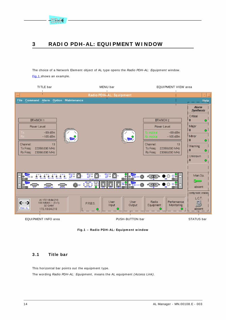
The choice of a Network Element object of AL type opens the Radio PDH-AL: Equipment window.
Fig.1 shows an example.
Fig.1 – Radio PDH-AL: Equipment window
3.1 Title bar
This horizontal bar points out the equipment type.
The wording Radio PDH-AL: Equipment, means the AL equipment (Access Link).
TITLE bar MENU bar EQUIPMENT VIEW area
EQUIPMENT INFO area PUSH-BUTTON bar STATUS bar
AL Manager - MN.00108.E - 003 15
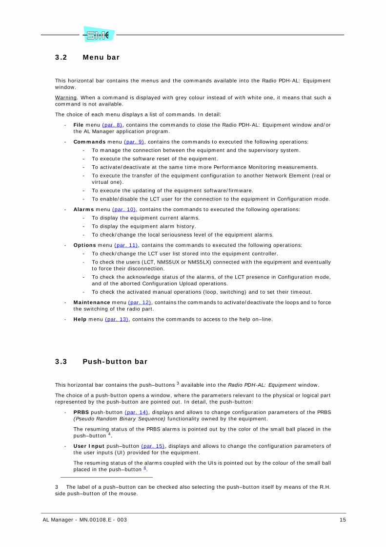
3.2 Menu bar
This horizontal bar contains the menus and the commands available into the Radio PDH-AL: Equipmentwindow.
Warning. When a command is displayed with grey colour instead of with white one, it means that such acommand is not available.
The choice of each menu displays a list of commands. In detail:
- File menu (par. 8), contains the commands to close the Radio PDH-AL: Equipment window and/orthe AL Manager application program.
- Commands menu (par. 9), contains the commands to executed the following operations:
- To manage the connection between the equipment and the supervisory system.
- To execute the software reset of the equipment.
- To activate/deactivate at the same time more Performance Monitoring measurements.
- To execute the transfer of the equipment configuration to another Network Element (real orvirtual one).
- To execute the updating of the equipment software/firmware.
- To enable/disable the LCT user for the connection to the equipment in Configuration mode.
- Alarms menu (par. 10), contains the commands to executed the following operations:
- To display the equipment current alarms.
- To display the equipment alarm history.
- To check/change the local seriousness level of the equipment alarms.
- Options menu (par. 11), contains the commands to executed the following operations:
- To check/change the LCT user list stored into the equipment controller.
- To check the users (LCT, NMS5UX or NMS5LX) connected with the equipment and eventuallyto force their disconnection.
- To check the acknowledge status of the alarms, of the LCT presence in Configuration mode,and of the aborted Configuration Upload operations.
- To check the activated manual operations (loop, switching) and to set their timeout.
- Maintenance menu (par. 12), contains the commands to activate/deactivate the loops and to forcethe switching of the radio part.
- Help menu (par. 13), contains the commands to access to the help on–line.
3.3 Push-button bar
This horizontal bar contains the push–buttons 3 available into the Radio PDH-AL: Equipment window.
The choice of a push-button opens a window, where the parameters relevant to the physical or logical partrepresented by the push-button are pointed out. In detail, the push-button:
- PRBS push-button (par. 14), displays and allows to change configuration parameters of the PRBS(Pseudo Random Binary Sequence) functionality owned by the equipment.
The resuming status of the PRBS alarms is pointed out by the color of the small ball placed in thepush–button 4.
- User Input push–button (par. 15), displays and allows to change the configuration parameters ofthe user inputs (UI) provided for the equipment.
The resuming status of the alarms coupled with the UIs is pointed out by the colour of the small ballplaced in the push–button 4.
3 The label of a push–button can be checked also selecting the push–button itself by means of the R.H.side push–button of the mouse.

16 AL Manager - MN.00108.E - 003
- User Output push–button (par. 16), displays and allows to change the configuration parametersof the user output (UO) provided for the equipment.
- Radio Equipment push-button (par. 17), displays and allows to change the radio parameters ofthe equipment.
The resuming status of the radio alarms is pointed out by the colour of the small ball placed in thepush–button 4.
- Performance Monitoring push–button (par. 18), allows to activate/deactivate the PM measure-ments; to set the threshold levels of the control parameters.
The resuming status of the PM alarms is pointed out by the colour of the small ball placed in thepush–button 4.
- Eq. EAST push–button (par. 19), displays and allows to change the configuration parameters of theeast branch of the equipment 5.
The resuming status of the east branch alarms is pointed out by the colour of the small ball placedin the push–button 4.
- Eq. WEST push–button (par. 19), displays and allows to change the configuration parameters ofthe west branch of the equipment 5.
The resuming status of the west branch alarms is pointed out by the colour of the small ball placedin the push–button 4
3.4 Status bar
This vertical bar contains the status information pointed out at Fig.2.
Warning. If the Radio PDH-AL: Equipment window refers to a virtual equipment, the information presentinto the status bar are not significant ones.
4 With details:
- The green color points out that it has not been activated any alarm.
- The red, orange, yellow or light blue color points out that it has been activated at least onealarm and the most serious activated alarm has respectively the Critical, Major, Minor orWarning seriousness level.
Warning. If the Radio PDH-AL: Equipment window refers to a virtual equipment, the resuming sta-tus of the alarms is not a significant one (the colour of the small ball is white).
5 The option is available only for PDH-AL equipment Terminal 16x2 East-West type.

AL Manager - MN.00108.E - 003 17
Fig.2 – Status bar (Radio PDH-AL: Equipment window)
Fig.2 notes
(1) The wording:
- Absent, points out that it has not been activated any manual operation.
- Present, points out that it has been activated at least one manual operation.
Selecting quickly twice the box, the system displays the Active Manual Operations window (refer toFig.9).
(2) The wording:
- Enabled, points out that the LCT user can activate the LCT–equipment connection as in Mon-itoring mode as in Configuration one.
- Disabled, points out that the LCT user can activate the LCT–equipment connection in Moni-toring mode only.
The setting of the parameter can be changed 9.7.
Warning. Without taking into account the preceding setting, when the user disconnects the equip-ment, the parameter is automatically enabled (enabled value).
(3) The wording:
- Absent, points out that the LCT–equipment connection (par. 28) has not been activated.
- Monitor, points out that the LCT–equipment connection has been activated in Monitoringmode.
- Config, points out that the LCT–equipment connection has been activated in Configurationmode.
Resume of the activation status relevant to the equipment alarms (subdivided ac-cording to their seriousness level).Each box points out a different serious-ness level of the alarm.The status of each level is represented by the colour of the “small ball”. With details:
- The green colour points out that it hasnot been activated any alarm, belong-ing to the specific level, into the equip-ment.
- The colour coupled with the level (Crit-ical–red, Major–orange, Minor–yellow,Warning–light blue, Unknown–blue)points out that it is present at leastone alarm of the specific level.The number of the activated alarms ispointed out under the name of the lev-el.
Warning. The supervision system couples with the Unknown level all the alarms for-warded by the equipment that have an unknown seriousness level (for every kind of trouble).
Activation status of the manualoperations (loop, switching) (1)
Connection status between the LCTprogram and the equipment (3)
Enabling status of the LCT user forthe connection with the equipment
in Configuration mode (2)

18 AL Manager - MN.00108.E - 003
3.5 Equipment view area
Fig.3 shows the equipment view area and its elements.
Fig.3 – Equipment view area (Radio PDH-AL: Equipment window)
Fig.3 notes
(1) With details:
- The Disable Alarms box, is displayed if the equipment has at least one alarm or the forward-ing of a trap disabled. The total number of disabled alarms and/or of trap forwarding is point-ed out after the Disable Alarms wording.
- The Incorrect Upload box is displayed when the last operation of information acquisition(Configuration Upload) executed by the supervision system was wrong.
(2) For each branch 6 in the field:
- Tx, the power (expressed in dBm) in output to the transmitter of the specific branch is dis-played.In the equipment of 1+1 isofrequential configuration, in the Tx row related to the stand–bybranch, there is the Standby. wording
- Rx, the power in input to the receiver of the specific branch is displayed.Warning. The Prx indication is referred to the 1+0 configuration. The additional looses forthe 1+1 systems are not included.
Both the powers are measured at the antenna flange.
6 For the AL equipment:
- In 1+0 configuration, the branch 1 is present
- In 1+1 configuration, the branches 1 and 2 are present.
- Of Terminal 16x2 East-West type, the East and West branches are present.
Warning. The branch called East is equivalent to branch 1 and the West branch is equivalentto branch 2 of an equipment in 1+1 configuration.
Warning boxes (1) Current values of the radio parameters (2)
Front view of the AL relevant to the Radio PDH-AL: Equipment window (3)
AL Manager - MN.00108.E - 003 19
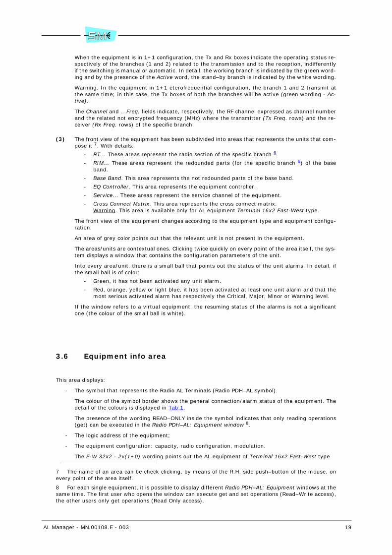
When the equipment is in 1+1 configuration, the Tx and Rx boxes indicate the operating status re-spectively of the branches (1 and 2) related to the transmission and to the reception, indifferentlyif the switching is manual or automatic. In detail, the working branch is indicated by the green word-ing and by the presence of the Active word, the stand–by branch is indicated by the white wording.
Warning. In the equipment in 1+1 eterofrequential configuration, the branch 1 and 2 transmit atthe same time; in this case, the Tx boxes of both the branches will be active (green wording - Ac-tive).
The Channel and ...Freq. fields indicate, respectively, the RF channel expressed as channel numberand the related not encrypted frequency (MHz) where the transmitter (Tx Freq. rows) and the re-ceiver (Rx Freq. rows) of the specific branch.
(3) The front view of the equipment has been subdivided into areas that represents the units that com-pose it 7. With details:
- RT... These areas represent the radio section of the specific branch 6.
- RIM... These areas represent the redounded parts (for the specific branch 6) of the baseband.
- Base Band. This area represents the not redounded parts of the base band.
- EQ Controller. This area represents the equipment controller.
- Service... These areas represent the service channel of the equipment.
- Cross Connect Matrix. This area represents the cross connect matrix.Warning. This area is available only for AL equipment Terminal 16x2 East-West type.
The front view of the equipment changes according to the equipment type and equipment configu-ration.
An area of grey color points out that the relevant unit is not present in the equipment.
The areas/units are contextual ones. Clicking twice quickly on every point of the area itself, the sys-tem displays a window that contains the configuration parameters of the unit.
Into every area/unit, there is a small ball that points out the status of the unit alarms. In detail, ifthe small ball is of color:
- Green, it has not been activated any unit alarm.
- Red, orange, yellow or light blue, it has been activated at least one unit alarm and that themost serious activated alarm has respectively the Critical, Major, Minor or Warning level.
If the window refers to a virtual equipment, the resuming status of the alarms is not a significantone (the colour of the small ball is white).
3.6 Equipment info area
This area displays:
- The symbol that represents the Radio AL Terminals (Radio PDH–AL symbol).
The colour of the symbol border shows the general connection/alarm status of the equipment. Thedetail of the colours is displayed in Tab.1.
The presence of the wording READ–ONLY inside the symbol indicates that only reading operations(get) can be executed in the Radio PDH–AL: Equipment window 8.
- The logic address of the equipment;
- The equipment configuration: capacity, radio configuration, modulation.
The E-W 32x2 - 2x(1+0) wording points out the AL equipment of Terminal 16x2 East-West type
7 The name of an area can be check clicking, by means of the R.H. side push–button of the mouse, onevery point of the area itself.
8 For each single equipment, it is possible to display different Radio PDH–AL: Equipment windows at thesame time. The first user who opens the window can execute get and set operations (Read–Write access),the other users only get operations (Read Only access).

20 AL Manager - MN.00108.E - 003
- The equipment IP address.
The Virtual Equipment wording points out that the Radio PDH–AL: Equipment window refers to avirtual NE object.
Tab.1- Equipment connection/alarm status
Colour of the edge
Description
Green The equipment is in connected status and it has not been activated any alarm.
Red a
a By default, the colour of the symbol edge displays always the colour of the most serious alarmpresent into the equipment.
The equipment is in connected status and it has been activated at least one alarmwith Critical level.
Orange aThe equipment is in connected status and it has been activated at least one alarmwith Major level.
Yellow aThe equipment is in connected status and it has been activated at least one alarmwith Minor level.
Light blue aThe equipment is in connected status and it has been activated at least one alarmwith Warning level.
BlueThe equipment is in connected status and it has been activated the LCT–equipmentconnection in Configuration mode.
Red with Xon the symbol
The equipment is in an unreachable status.
GreyThe equipment is in disconnected status or the Radio PDH-AL: Equipment windowrefers to a virtual equipment.
AL Manager - MN.00108.E - 003 21
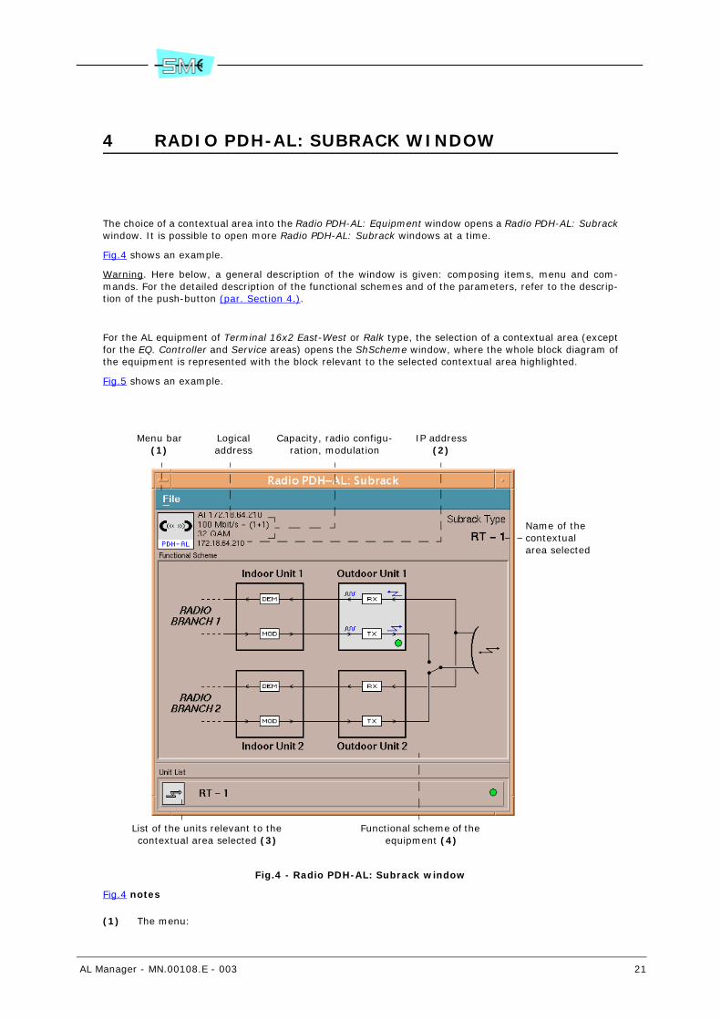
4 RADIO PDH-AL: SUBRACK WINDOW
The choice of a contextual area into the Radio PDH-AL: Equipment window opens a Radio PDH-AL: Subrackwindow. It is possible to open more Radio PDH-AL: Subrack windows at a time.
Fig.4 shows an example.
Warning. Here below, a general description of the window is given: composing items, menu and com-mands. For the detailed description of the functional schemes and of the parameters, refer to the descrip-tion of the push-button (par. Section 4.).
For the AL equipment of Terminal 16x2 East-West or Ralk type, the selection of a contextual area (exceptfor the EQ. Controller and Service areas) opens the ShScheme window, where the whole block diagram ofthe equipment is represented with the block relevant to the selected contextual area highlighted.
Fig.5 shows an example.
Fig.4 - Radio PDH-AL: Subrack window
Fig.4 notes
(1) The menu:
List of the units relevant to the contextual area selected (3)
Functional scheme of the equipment (4)
Menu bar(1)
Logicaladdress
Capacity, radio configu-ration, modulation
IP address (2)
Name of the contextual area selected

22 AL Manager - MN.00108.E - 003
- File, contains the following commands:
- Main Window, it brings at front or opens again the Radio PDH-AL: Equipment window.
- Close, it closes the Radio PDH-AL: Subrack window under examination.
If there are not other Radio PDH-AL… windows already open, the command closes also theAL Manager application program.
In this second case only, at the command choice, the system displays a confirmation win-dow. Choose the Yes push–button to execute the operation.
- Exit, it closes all the Radio PDH-AL… windows actually open (comprised also the Radio PDH-AL: Equipment window, if it has been open) and the AL Manager application program.
At the command choice, the system displays a confirmation window. Choose the Yes push–button to execute the operation.
- Help, contains the commands to access to the help on line.
(2) The Virtual Equipment wording points out that the window refers to a virtual NE object.
(3) The functional scheme is usually displayed by blocks.
Double click on a block with the left button of the mouse: opens a Radio PDH-AL: Unit window (seeFig.6) where the parameters and the alarms relevant to the selected block are listed.
The general status of the alarms relevant to the block is pointed out by the color of the small ball:
- Green, it has not been activated any alarm relevant to the specific block.
- Red, orange, yellow or light blue, it has been activated at least one alarm relevant to theblock and that the most serious activated alarm has respectively the Critical, Major, Minoror Warning level.
If the window refers to a virtual equipment, the resuming status of the alarms is not a significantone (the colour of the small ball is white).
(4) Each unit is represented by a rectangle that points out the graphical symbol, the name and the sta-tus of the unit alarms.
If the user quickly selects twice a unit, the system opens the Radio PDH-AL: Unit window (see Fig.6)that lists the unit characteristics (name, version, etc.).
The general status of the unit alarms is pointed out by the color of the small ball:
- Green, it has not been activated any alarm relevant to the specific unit.
- Red, orange, yellow or light blue, it has been activated at least one alarm relevant to thespecific unit and that the most serious activated alarm has respectively the Critical, Major,Minor or Warning level.
If the window refers to a virtual equipment, the resuming status of the alarms is not a significantone (the colour of the small ball is white).
AL Manager - MN.00108.E - 003 23
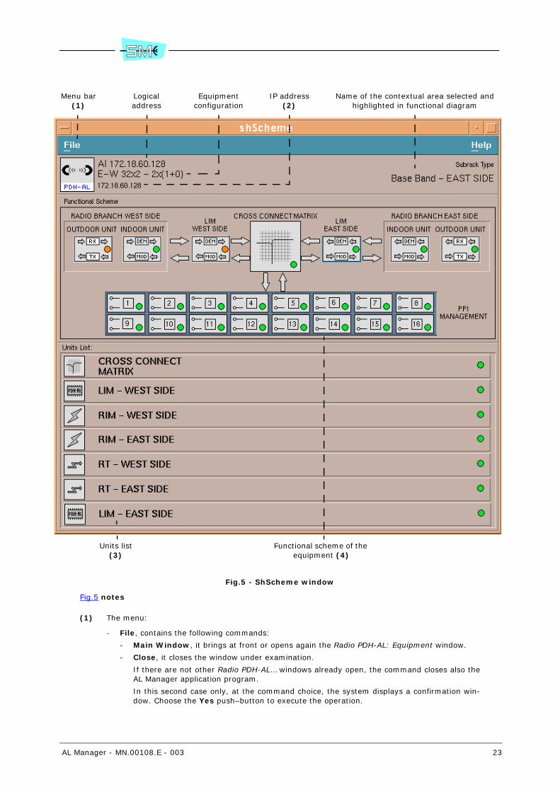
Fig.5 - ShScheme window
Fig.5 notes
(1) The menu:
- File, contains the following commands:
- Main Window, it brings at front or opens again the Radio PDH-AL: Equipment window.
- Close, it closes the window under examination.
If there are not other Radio PDH-AL… windows already open, the command closes also theAL Manager application program.
In this second case only, at the command choice, the system displays a confirmation win-dow. Choose the Yes push–button to execute the operation.
Units list(3)
Functional scheme of the equipment (4)
Menu bar(1)
Logicaladdress
Equipmentconfiguration
IP address (2)
Name of the contextual area selected and highlighted in functional diagram

24 AL Manager - MN.00108.E - 003
- Exit, it closes all the Radio PDH-AL… windows actually open (comprised also the Radio PDH-AL: Equipment window, if it has been open) and the AL Manager application program.
At the command choice, the system displays a confirmation window. Choose the Yes push–button to execute the operation.
- Help, contains the commands to access to the help on line.
(2) The Virtual Equipment wording points out that the window refers to a virtual NE object.
(3) The functional scheme is usually displayed by blocks.
The highlighted block (blue margin) is the block which the selected contextual area refers to.
Double click on a block with the left button of the mouse: opens a Radio PDH-AL: Unit window (seeFig.6) where the parameters and the alarms relevant to the selected block are listed.
The general status of the alarms relevant to the block is pointed out by the color of the small ball:
- Green, it has not been activated any alarm relevant to the specific block.
- Red, orange, yellow or light blue, it has been activated at least one alarm relevant to theblock and that the most serious activated alarm has respectively the Critical, Major, Minoror Warning level.
If the window refers to a virtual equipment, the resuming status of the alarms is not a significantone (the colour of the small ball is white).
(4) Each unit is represented by a rectangle that points out the graphical symbol, the name and the sta-tus of the unit alarms.
If the user quickly selects twice a unit, the system opens the Radio PDH-AL: Unit window (see Fig.6)that lists the unit characteristics (name, version, etc.).
The general status of the unit alarms is pointed out by the color of the small ball:
- Green, it has not been activated any alarm relevant to the specific unit.
- Red, orange, yellow or light blue, it has been activated at least one alarm relevant to thespecific unit and that the most serious activated alarm has respectively the Critical, Major,Minor or Warning level.
If the window refers to a virtual equipment, the resuming status of the alarms is not a significantone (the colour of the small ball is white).
AL Manager - MN.00108.E - 003 25
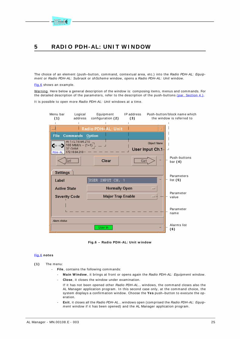
5 RADIO PDH-AL: UNIT WINDOW
The choice of an element (push–button, command, contextual area, etc.) into the Radio PDH-AL: Equip-ment or Radio PDH-AL: Subrack or shScheme window, opens a Radio PDH-AL: Unit window.
Fig.6 shows an example.
Warning. Here below a general description of the window is: composing items, menus and commands. Forthe detailed description of the parameters, refer to the description of the push-buttons (par. Section 4.).
It is possible to open more Radio PDH-AL: Unit windows at a time.
Fig.6 – Radio PDH-AL: Unit window
Fig.6 notes
(1) The menu:
- File, contains the following commands:
- Main Window, it brings at front or opens again the Radio PDH-AL: Equipment window.
- Close, it closes the window under examination.
If it has not been opened other Radio PDH-AL… windows, the command closes also theAL Manager application program. In this second case only, at the command choice, thesystem displays a confirmation window. Choose the Yes push–button to execute the op-eration.
- Exit, it closes all the Radio PDH-AL… windows open (comprised the Radio PDH-AL: Equip-ment window if it has been opened) and the AL Manager application program.
Menu bar(1)
Logical address
IP address (3)
Push-button/block name which the window is referred to
Push-buttons bar (4)
Parameters list (5)
Parameter value
Parameter name
Alarms list (6)
Equipmentconfiguration (2)
26 AL Manager - MN.00108.E - 003
At the choice of the command, the system displays a confirmation program. Choose theYes push–button to execute the operation.
- Commands, contains the following commands:
- Refresh, it updates the information present into the window.
- Clear, it remove the selection on all the parameters selected for the get or set parame-ters.
- Send GET Request, it executes the get operation (par. 5.2) for all the parameters se-lected for such an operation.
Warning. The command is available only if it has been selected a parameter for the getoperation.
The choice of this command is equal to the choice of the Get push–button.
- Send SET Request, it executes the set operation (par. 5.1) for all the parameters se-lected for such an operation.
Warning. The command is available only if it has been selected at least one parameterfor the set operation.
The choice of this command is equal to the choice of the Set push–button.
- Option, contains the following commands:
- Select All (Get), it selects all the parameters, present into the window, for which it ispossible to execute the get operation with the exception of the parameters already se-lected for the set operation.
- Help, contains the commands to access to the help on line.
(2) In order, capacity, radio configuration and modulation are pointed out.
The E-W 32x2 - 2x(1+0) wording points out the AL equipment of Terminal 16x2 East-West type
(3) The Virtual Equipment wording points out that the window refers to a virtual NE object.
(4) The push-button:
- Set, it executes the set operation (par. 5.1) for all the parameters selected for such an op-eration.
Warning. The push–button is available only if it has been selected at least one parameter forthe set operation.
The choice of this push–button is equal to the choice of the Send SET Request command.
- Clear, it removes the selection of all the parameters selected for the get or set operation.
Warning. The push–button is available only if it has been selected at least one parameter forthe get or set operation.
The choice of this push–button is equal to the choice of the Clear command.
- Get, it executes the get operation (par. 5.2) for all the parameters selected for such an op-eration.
Warning. The push–button is available only if it has been selected at least one parameter forthe get operation.
The choice of this push–button is equal to the choice of the Send GET Request command.
(5) Each line represents a parameter.
In some window, the parameters are subdivided into tabs. The activation of a tab shows only theparameters present in it. To display the parameters of a different tab, select the name of the tabitself.
When the name of the parameter appears with grey color, it means that such a parameter is notavailable because it is not a significant one into the current situation.
The values of some parameters can be changed by the NMS5UX/NMS5LX user (set operation), thevalues of other parameters can be read only (get operation), other values can be as read as set.
Warning. When an attribute has been selected for a get operation, it cannot be selectedfor a set operation and vice versa.
(6) Each alarm is represented by a rectangle that points out the alarm short name (par. 27).
The alarm status is pointed out by the color of the rectangle background:
- The green color, the alarm has not been activated.

AL Manager - MN.00108.E - 003 27
- The red, orange, yellow or light blue color, the alarm has been activated and it has respec-tively the Critical, Major, Minor or Warning seriousness level.
- The grey color, the alarm has been disabled 9 or the window refers to a virtual equipmentwith the alarm status that is a not significant one.
Warning. Not all the Radio PDH-AL: Unit windows are provided with the alarm list.
5.1 Set operation
The set operation is the possibility to change the value of a parameter and to forward it to the equipmentin such a way that it replaces the current value of such parameter.
The attributes for which it is possible to execute a set operation have the relevant value pointed out forexample into a text box, into a pop–up menu or into every element that allows to change such a value 10.
After having changed a parameter, the system displays an arrow: on the L.H. side of its name.
To execute the writing operation, choose the Set push–button or the Send SET Request command.
At the end of the operation, if such an operation has been successfully executed, the arrow disappears; onthe contrary, if the operation is not successfully executed, the arrow is marked by means of a red cross:
.
It is possible to execute at the same time the writing of more parameters, changing their values one afterthe other and then choosing the above mentioned push–button or command.
Warning. The parameters with the value that is not contained into an element that allows their changingcan not be selected for the set operation.
5.2 Get operation
The get operation is the possibility to require to the equipment the forwarding to the supervisory systemof the value currently set.
The setting of a parameter for the get operation consists of clicking twice on the parameter name: thesystem displays an arrow: , on the L.H. side of the parameter.
To execute the reading operation, choose the Get push–button or the Send GET Request command.
At the end of the operation, if such an operation has been successfully executed, the arrow disappears andthe system displays the read value; on the contrary, if the operation is not successfully executed, the arrowis marked by means of a red cross .
It is possible to execute at the same time the reading of more parameters, selecting them one after theother and then choosing the above mentioned push–button or command.
Warning. The attributes are not all selectable for the get operation.
9 The alarm disabling operation is pointed out also into the Radio PDH-AL Equipment window by meansof a warning box (refer to Fig.3).
10 The modes to change the value of a parameter are pointed out time by time into the paragraph thatdescribes the parameter itself.

28 AL Manager - MN.00108.E - 003
5.3 Get and Set operations for the virtual equipment
If the Radio PDH-AL: Unit window refers to a virtual equipment (par. 7), the get operation will not be avail-able for any parameter present into the window.
While the set operation can be executed for all the parameters for which it is available, but during a possibletransfer operation of the virtual equipment configuration to another equipment (par. 9.5), the system willtransfer only the parameters that have the symbol , on the side of the value.
AL Manager - MN.00108.E - 003 29
Section 3.OPERATING PROCEDURES
6 OPENING/CLOSING OF THE RADIO PDH-AL: EQUIPMENT WINDOW
The subject chapter contains the opening (par. 6.1) / closing (par. 6.2) mode of the window.
Warning. Before opening the Radio PDH-AL: Equipment window, check that:
- The AL Manager application program has been installed and enabled for functioning.
To check the presence of the application program, select the Help – About NMS5UX or Help– About NMS5LX command present into the NMS5UX or NMS5LX graphical interface.
If the application program is not present, contact the system administrator.
- The NMS5UX or NMS5LX graphical interface has been opened.
The starting–up mode of the NMS5UX or NMS5LX graphical interface is described into theNMS5UX or NMS5LX user manual.
- The network that contains the AL equipment has been configured and it has been created therelevant Network Element object.
The procedure to represent graphically the equipment network and to create the NE objects isreported into the NMS5UX or NMS5LX user manual.
- The connection between the supervisory system and the equipment has been activat-ed AT LEAST one time.
The procedure to connect a NE is reported into the NMS5UX o NMS5LX user manual.
The above mentioned consideration are necessary only if the NE object, for which the user wantsto open the Radio PDH-AL: Equipment window, is really present into the network 11.
11 The NMS5UX or NMS5LX system allows creating NE objects that do not have a corresponding equip-ment present into the network, but for such ones, it is possible to open the Radio PDH-AL: Equipment win-dow. These equipment are called virtual ones.

30 AL Manager - MN.00108.E - 003
6.1 Opening of the Radio PDH-AL: Equipment window
1 Into the NMS5UX/NMS5LX graphical interface, select twice quickly the NE object that represent thedesired Radio PDH-AL: Equipment. The Fig.7 shows an example.
The Radio PDH-AL: Equipment window opens (refer to Fig.1).
If the selected equipment is in:
- Connected status 12, the functioning status (alarms) and the configuration, pointed out intothe window, corresponds to the real condition present into the equipment.
- Disconnected or unreachable status, the functioning status and the displayed configurationcorrespond to the last known configuration.
Warning. If at the double selection of the NE symbol, the system does not open the Radio PDH-AL:Equipment window but on the contrary it opens the Radio PDH-AL one, it means that the selectedNE object refers to a virtual object (par. 7) for which the system has never opened the Radio PDH-AL: Equipment window.
Fig.7 – NE object, AL type
6.1.1 Messages displayed at the window opening
At the opening of the Radio PDH-AL: Equipment window, the system can display one of the following mes-sages:
- Equipment never connected. Equipment is in disconnected status and that it has never beenconnected from the creation time of the relevant Network Element object 13.
In this case, the system does not open the Radio PDH-AL: Equipment window. To open it, it isnecessary before activating at least one time the connection with the equipment.
The procedure to connect a NE is described into the NMS5UX or NMS5LX user manual.
- Read only mode. Another user has opened equipment. The Radio PDH-AL: Equipment window,relevant to the equipment is actually already opened by another user.
For the user under examination, the window is opened in Read Only modality. In this modality,it is possible only to execute only reading operation.
If the profile of the user is superuser, he can then force the closing of the Radio PDH-AL: Equip-ment window relevant to the other user 14.
- Equipment <IP address>. Unreacheable. Equipment is in unreachable status.
In this case, the system opens the Radio PDH-AL: Equipment window, but the displayed infor-mation could not correspond to the real configuration of the equipment.
12 And the LCT program is not connected to the equipment in Configuration mode (par. 28).
13 This situation is caused because, when the supervisory system is not connected to an equipment andthe user asks to open the relevant Radio PDH-AL Equipment window, the supervisory system itself takesthe information concerning the configuration of its own database. If the equipment has never been con-nected, the system has not any information concerning the configuration of such an equipment into its owndatabase, then it does not allow the opening of the window.
14 The procedure to require/force the closing of the Radio PDH-AL: Equipment window, relevant to an-other user, is reported into the NMS5UX or NMS5LX user manual.
NElogicaladdress

AL Manager - MN.00108.E - 003 31
- Equipment in Maintenance mode. Please wait until the operation is completed or press OK buttonto exit. Equipment is in transient status 15.
If you wish to cancel the operation (opening of the Radio PDH-AL: Equipment window) selectthe OK push-button, otherwise it is necessary to wait that the equipment passes from the tran-sitory status to another status (for example, connected) which allows the opening of the win-dow.
Warning. If the system displays other error messages that does not allow the opening of the Radio PDH-AL: Equipment window, such as for instance Unable to register to Daemon, contact the relevant systemadministrator.
6.1.2 Messages displayed when the window is open
When the Radio PDH-AL: Equipment window is open, the system can display one of the following messag-es:
- Equipment in Maintenance mode. Please wait until the operation is completed or press OK buttonto exit. The equipment is passed to transitory status (maintenance) 15.
If you wish to close the Radio PDH-AL: Equipment window select the OK push-button, otherwisewait that the equipment passes from the transitory status to another one (for example, connect-ed). In this second, the Radio PDH-AL: Equipment window is closed and automatically re-opened.
- AL Manager <logic and physical address of the equipment>: Received a logout request fromUser <user name> press OK to exit your manager session. WARNING! If you don’t acknowledgethis dialog in 30 seconds your session will automatically be closed. A NMS5UX/NMS5LX user hasrequired the closing of the Radio PDH-AL: Equipment window 14.
If the user chooses the Cancel push–button, the system refuses the request: the window doesnot close.
If the user chooses the OK push–button or he does not choose any other push–button within 30seconds from the message displaying, the system does not accept the request: the window clos-es.
- WARNING. AL Manager <logic and physical address of the equipment>: Forced Logout Supe-ruser. NMS5UX/NMS5LX user with superuser profile has forced the closing of the Radio PDH-AL:Equipment window 14.
The displaying of this message automatically closes the window.
Warning. If the system displays other error messages that automatically close the Radio PDH-AL: Equip-ment window, such as for instance Daemon is Down. Manager is Closing, contact the involved system ad-ministrator.
15 The equipment assumes the maintenance status after one of the following conditions:
- It has been changed a configuration parameter that is followed by a software reset of theequipment.
- It has been forwarded a software reset of the equipment (par. 9.1).
- The user or the system has forwarded the Configuration Upload command.
The system automatically forwards this command in all the situations when it is supposedthat the equipment real configuration and the one memorized into the system database aremisaligned.
For instance, when the LCT user connected with the equipment in Configuration mode, dis-connects himself from the equipment, the system forwards the command to get the possiblechanges of configuration executed by the LCT user or when the timeout coupled with theactive manual operations expires, such manual operations are deactivated.
More information concerning the equipment statuses are reported into the NMS5UX/NMS5LX manual.

32 AL Manager - MN.00108.E - 003
6.1.3 Updating of the information present into the window
When the Radio PDH-AL: Equipment has been opened, the displayed information (alarms, connection sta-tus, etc.) are dynamically updated only if the equipment is in connected status, the window access is Read–Write the LCT in Configuration mode is not connected to the equipment 16.
If the Radio PDH-AL: Equipment window is in Read Only modality, the alarms are not automatically updateddynamically. To update the alarms, select the Commands – Alarm Realignment command (par. 9.2).
If the equipment is in disconnected or unreachable status, the displayed information (with the exceptionof the equipment status) refer to the last known configuration stored into the database of the supervisorysystem.
6.1.4 Opening of more Radio PDH-AL: Equipment windows
It is possible to open more Radio PDH-AL: Equipment windows related to the same equipment.
The first user who opens the window will access in Read–Write and he can execute only reading (get) andwriting (set) operations.
The other users who open the window will have Read Only access and can execute only reading operations(get).
Besides, it is possible to open more Radio PDH-AL: Equipment windows relevant to different AL equipment.
6.1.5 User profile (Superuser, Privileged, Advanced, etc.)
Each NMS5UX or NMS5LX user is characterized by a profile that defines the use of the commands availableinto the NMS5UX or NMS5LX graphical interface.
The NMS5UX or NMS5LX user, who opens the Radio PDH-AL: Equipment window, keeps his profile.
For instance, if a user with Advanced profile opens the NMS5UX or NMS5LX graphical interface, such a pro-file is kept also into the Radio PDH-AL: Equipment windows that will be opened.
The availability of the menus, of the commands and of the push–buttons, present into the Radio PDH-AL:Equipment window according to the different profiles, are pointed out in 26.
6.2 Closing of the Radio PDH-AL: Equipment window
To close the Radio PDH-AL: Equipment window and the AL Manager application program, choose the File-Exit command (par. 8.2).
Warning. If there are other Radio PDH-AL... windows opened, the user can close the Radio PDH-AL: Equip-ment window and he can not close the AL Manager application program: File-Close command (par. 8.1).
The closing of the Radio PDH-AL: Equipment window and /or of the AL Manager application program doesnot affect in any way the connection status of the equipment.
16 In this case, the NMS5UX/NMS5LX user can check the equipment configuration (that can correspondsto the one really present on the equipment), but it can not change the parameters. When the LCT userdisconnects himself from the equipment, the supervisory system automatically forwards a ConfigurationUpload command.

AL Manager - MN.00108.E - 003 33
6.2.1 Automatic closing of the window
The Radio PDH-AL: Equipment window and the AL Manager application program are automatically closedwhen:
- The system displays the message WARNING. AL Manager <logic and physical address of theequipment>: Forced Logout Superuser or an Error message.
- The user closes the NMS5UX or NMS5LX graphical interface and/or the operation system.
- The user changes the map.
The Radio PDH-AL: Equipment window and the AL Manager application program are automatically closedand opened when the system displays the message Equipment in Maintenance mode…
34 AL Manager - MN.00108.E - 003
7 AL VIRTUAL EQUIPMENT
With AL virtual equipment we mean a Network Element object of AL type, created by the user which hasnot a corresponding AL present in the network.
For these equipment, it is possible to open the relevant Radio PDH-AL: Equipment window 17 and to setthe configuration parameters, the user inputs, the user outputs, the control parameters for the Perform-ance Monitoring measurements, etc. (par. 7.1).
Later, the configuration of the virtual equipment can be transferred to a generic equipment (virtual or reallypresent into the network) compatible with the virtual one under examination (par. 9.5).
7.1 To configure an AL virtual equipment
1 In the NMS5UX/NMS5LX graphic interface, double click with the left button of the mouse on the NEobject that represents the wished virtual AL equipment 18.
First time you select a virtual AL, the Radio PDH-AL window, depicted in Fig.8, opens.
a To set the parameters according to the type of the virtual equipment to be created.
In order to modify the value of a parameter, select the relevant folder and choose the valuefrom the list.
Warning. If a parameter is disabled, it means that it is not available for the set equipmenttype/configuration.
b Choose the Ok push–buttons.
The system displays the Radio PDH-AL: Equipment window 19.
At the next selections of the virtual AL, the Radio PDH-AL: Equipment window will be automaticallydisplayed 19.
2 To configure the equipment, as if it was a real equipment, using the push–buttons and the contex-tual areas present into the window.
Some parameters, for which the set operation (par. 5.1) is available, have on the left of their valuethe symbol . This symbol points out that such parameters will be really transferred to anotherequipment (real or virtual one) during the download configuration (par. 9.5).
17 For the real equipment, to execute this operation, it is necessary to activate he connection betweenthe system and the equipment itself.
18 The procedure to create a virtual equipment is reported into the NMS5UX/NMS5LX user manual.
19 Some fields, present into the window, will not be available because they are not significant ones for avirtual equipment such as for instance: Alarm Synthesis, LCT, etc.

AL Manager - MN.00108.E - 003 35
Fig.8 – Radio PDH-AL window (virtual AL)
Fig.8 notes
(1) The box:
- Protection. Protection type of the equipment:
- 1+0. Equipment in not protected configuration.
- 1+1 Iso Frequency. Equipment in isofrequential type protected configuration (Hot Stand-by).
- 1+1 Hetero Frequency. Equipment in heterofrequential type protected configuration(Frequency Diversity).
- Eq Type. Equipment type:
- PDH–AL–C. PDH–AL equipment compact version.
- PDH–AL 1U. PDH–AL equipment 1 unit standard version.
- PDH–AL 2U. PDH–AL equipment 2 units version.
- PDH–AL 1U Eth. PDH–AL equipment 1 unit version with Ethernet Lan tributary.
- PDH–AL 1U Eth 100M. PDH–AL equipment version 1 unit with Ethernet Lan 10/100M trib-utary.
- Capacity. Equipment capacity: 2Mbit/s, 2x2Mbit/s, etc.
- Eq. Controller. Controller type:
- Unused. Not used parameter.
- Eq Ctrl2–4x2–120ohm. PDH–AL equipment compact version, 4x2 capacity, tributary withimpedance 120 ohm.
- Eq Ctrl2–4x2–75ohm. PDH–AL equipment compact version, 4x2 capacity, tributary withimpedance 75 ohm.
- Eq Ctrl2–4x2–Coax. PDH–AL equipment compact version, 4x2 capacity, tributary withcoaxial cable.
- Eq Ctrl2–8x2–120 ohm. PDH–AL equipment compact version, 8x2 capacity, tributarywith impedance 120 ohm.
- Eq Ctrl 2–8x2–75 ohm. PDH–AL equipment compact version, 8x2 capacity, tributary withimpedance 75 ohm.
- Base Band Config. Base band type:
- Unused. Not used parameter.
- 16x2–2U. PDH–AL equipment 2 units version, until 16x2Mbit/s capacity.
Logicaladdress
Configurationparameters
(1)

36 AL Manager - MN.00108.E - 003
- 32x2. PDH–AL equipment, 32x2 Mbit/s capacity.
- 32x2 east-west. PDH–AL equipment Terminal 16x2 East-West type.
- East Side Capacity. East branch capacity of the equipment: 4x2Mbit/s, 8x2Mbit/s, etc. 20.
- West Side Capacity. West branch capacity of the equipment: 4x2Mbit/s, 8x2Mbit/s, etc. 20.
20 Parameter meaningful only for AL equipment of Terminal 16x2 East-West type.

AL Manager - MN.00108.E - 003 37
Section 4.MENUS, PUSH-BUTTONS AND CONTEXTUAL AREAS
8 FILE (MENU)
The File menu contains the Close (par. 8.1) and Exit (par. 8.2) options.
8.1 File - Close
The Close option closes the Radio PDH-AL: Equipment window.
At the option choice:
- If there are not other Radio PDH-AL… windows already opened, the system displays the messageWarning. This is the last Manager window. Do You really want to exit Radio PDH-AL?
If the user chooses the Yes push–button, the system closes the Radio PDH-AL: Equipment win-dow and the AL Manager application program 21.
- If there are other Radio PDH-AL… windows already opened, the system closes the Radio PDH-AL: Equipment window (the other Radio PDH-AL… windows are not closed).
8.2 File - Exit
The Exit option closes the Radio PDH-AL: Equipment window and the AL Manager application.
At the choice of the command, the system displays a confirmation window.
21 In this case the option choice corresponds to the choice of the File - Exit option.

38 AL Manager - MN.00108.E - 003
The user has to choose the Yes push–button to execute the operation.
Warning. The closing operation of the Radio PDH-AL: Equipment window and of the AL Manager applicationcauses the closing of all the eventually opened Radio PDH-AL… windows.

AL Manager - MN.00108.E - 003 39
9 COMMANDS (MENU)
The Commands menu contains the following options:
- Reset Equipment Controller (par. 9.1). It executes the software reset of the equipment.
- Alarm Re–Alignment (par. 9.2). It acknowledges the alarm status currently present on theNE.
- Line Test (par. 9.3). It verifies the real reach ability of the NE.
- View/Modify P.M. Status (par. 9.4). It displays the status of the PM measures of the equip-ment and activates/deactivates, at the same time, more types of measures and/or measurepoints.
- Configuration Download (par. 9.5). It transfer the equipment configuration to another NE (re-al or virtual) of the same type.
- NE Sw/Fw Release (par. 9.6). It displays the version and updates the equipment software/firmware.
- Modify LCT Configuration Mode (par. 9.7). It enables/disables LCT program to connect to theequipment in Configuration modality.
9.1 Commands – Reset Equipment Controller
The Reset Equipment Controller command executes the software re–starting of the equipment (par.9.1.1).
This operation consists of the reset of all the communication channels 22 of the equipment.
Warning. The execution of this operation causes a temporarily disconnection of the equipment from thesupervisory system.
9.1.1 To reset the equipment
1 Choose the Commands – Reset Equipment Controller option.
The system displays a confirmation window.
2 Choose the Ok push–button.
The end of the operation is pointed out by means of a message that displays the result of the op-eration itself.
22 For instance, with the supervision system
40 AL Manager - MN.00108.E - 003
9.2 Commands – Alarm Re-alignment
The Alarm Re–Alignment option forces the equipment to forward its current alarms to the supervisorysystem (par. 9.2.1).
The re–aligning procedure causes the deleting of the information concerning the NE present into the cur-rent alarms table. Then, the system requires, to the NE, the status of its alarms and stores them into thecurrent alarms table 23.
Warning. The option under examination does not represent the normal procedure to get the functional sta-tus of a NE. Its use is advisable only if the user thinks that there has been a misalignment situation betweenthe alarm information known by the NMS5UX/NMS5LX system and the real alarm situation present into theNE.
9.2.1 To force the equipment to forward its current alarms
1 Choose, from the menu bar, the Commands – Alarm Re–Alignment option 24.
9.3 Commands – Line Test
The Line Test command checks the effective reach ability of the equipment from the supervisory system(par. 9.3.1).
This check consists of the request to the equipment, done by the NMS5UX/NMS5LX system, of the valuerelevant to the chosen parameter: if the NE answers, the test is successfully executed, on the contrary, itfails.
9.3.1 To check the reach ability of the equipment
1 Choose the Commands – Line Test command.
The end of the operation is pointed out by means of a message that displays the result of the op-eration itself.
9.4 Commands – View/Modify PM Status
The View/Modify PM Status option allows:
- To display the list of the PM measurements that characterize the equipment type under exami-nation.
For each measurement point, the system points out the functioning status of the relevant meas-urement.
23 The contents of the current alarms table can be displayed opening the Current Alarms Browser window.
24 Warning. The end of this operation is pointed out by a message.

AL Manager - MN.00108.E - 003 41
- To activate, at the same time, one or more PM measurements 25 for the equipment under ex-amination.
- To deactivate, at the same time, one or more PM measurements 25 for the equipment underexamination.
Warning. The above described operations are reported into the NMS5UX or NMS5LX user manual.
9.5 Commands – Configuration Download
The Configuration Download option allows:
- To transfer the configuration of the equipment under examination to one or more real NEs.
- To transfer the configuration of the equipment under examination to one or more virtual NEs.
Warning. The above described operations are reported into the NMS5UX or NMS5LX user manual.
9.6 Commands – NE SW/FW Release
The NE Sw/Fw Release option allows:
- To check the version of the equipment software/firmware relevant to the NE.
- To update the equipment software/firmware 26.
- To switch the functioning of the memory benches of the main controller.
Warning. The above described operations are reported into the NMS5UX or NMS5LX user manual.
9.7 Commands – Modify LCT Configuration Mode
The Modify LCT Configuration Mode option allows enabling/disabling the LCT user to be able to connecthimself to the equipment by means of the LCT program, in Configuration mode.
The current setting of this parameter is pointed out into the status bar of the Radio PDH-AL: Equipmentwindow (config. mode parameter - refer to Fig.2).
Warning. Without taking into account the preceding setting, when the AL object is turned off/turned onagain, the config. mode parameter results enabled (value of the parameter: enabled).
25 Measurement types and/or measurement points.
26 The equipment sw/fw is the assembly of all the sw/fw necessary for the management of the entire NE(sw/fw of the main controller and sw/fw of the peripheral units).
The equipment sw/fw is present into the main controller that is provided with two memory benches: thefirst one on service and the other one at rest.
Each memory bench can contain a version (also a different one) of the equipment sw/fw. It is possible toupdate the equipment sw/fw of a memory bench at a time.

42 AL Manager - MN.00108.E - 003
9.7.1 To enable the LCT user to be able to connect himself to the equip-ment by means of the LCT program, in Configuration mode
1 Choose the Commands – Modify LCT Configuration Mode – Enable option.
At the end of this operation, the system displays a message that points out the result of the oper-ation itself.
The value of the config. mode parameter switches from Disabled to Enabled.
LCT user can activate the connection with the equipment as in Monitoring mode as in Configurationone.
9.7.2 To disable the LCT user to be able to connect himself to the equip-ment by means of the LCT program, in Configuration mode
1 Choose the Commands – Modify LCT Configuration Mode – Disable option.
At the end of this operation, the system displays a message that points out the result of the oper-ation itself.
The value of the config. mode parameter switches from Enabled to Disabled.
LCT user can activate the connection with the equipment in Monitoring mode only.
AL Manager - MN.00108.E - 003 43
10 ALARMS (MENU)
The Alarms menu contains the following options:
- Current Alarms (par. 10.1). It displays the alarm27, status and event 28 signals actually acti-vated into the equipment.
- Alarm History (par. 10.2). It displays the history 29 of the alarm/status/event signals, storedinto the database of the NMS5UX/NMS5LX system, relevant to the equipment.
- Equipment Severity Code (par. 10.3). It enables/disables the alarm and the forwarding statusof the trap 30 executed by the NE to the system. It changes the local seriousness level of the NEalarms.
10.1 Alarms – Current Alarms
The Current Alarms option allows:
- To display the list of the alarm/event/status signals activated into the equipment.
- To save/print the signals list.
- To mark the signals in such a way that the system memorizes that the user has seen the signals.
- To freeze the window in such a way that it will not dynamically updated.
- To filter the signals list.
- To point out the NE symbol into the map window.
- To check the time between two different signals.
- To open the Equipment Info… window of the NE.
Warning. The above described operations are reported into the NMS5UX or NMS5LX user manual.
27 The wording alarm defines the failure signal created by an error or a malfunctioning of the NE or ofevery element inside it.
28 The wording status and event identify the signals that point out a status change, an operation onprogress or a functioning condition.
The status signals are spontaneously communicated by the NE to the system, such as for instance:
- The activation/deactivation of the connection between the LCT and the NE.
- The starting–up/end of the equipment software/firmware.
- The activated/stand–by status of doubled equipment parts.
The event signals are created by the supervisory system itself, such as the starting–up of an operation forthe alarm re–aligning.
29 The history is the list of the signals acquired and stored by the supervisory system. Into the alarmhistory, the system stores as the detection signal as the alarm reset one.
30 The trap is the message (in this case the detection message or the alarm reset one) spontaneouslyforwarded by the NE to the supervisory system.
44 AL Manager - MN.00108.E - 003
10.2 Alarms – Alarm History
The Alarm History option 31 allows:
- To display the history of the alarm/event/status signals of the equipment.
- To save/print the signals list.
- To copy, into a text editor, the signals list.
- To delete/mark the signals.
- To filter the signals list.
- To point out the NE symbol into the map window.
- To check the time between two different signals.
- To open the Equipment Info… window of the NE.
Warning. The above described operations are reported into the NMS5UX or NMS5LX user manual.
10.3 Alarms – Equipment Severity Code
The Equipment Severity Code option allows:
- To display the list of the alarm signals relevant to the NE.
For each signal, the system points out the alarm status (enabled/disabled) and the forwardingstatus of the relevant trap from the NE to the NMS5UX/NMS5LX system.
- To disable the alarms 32.
In this case the detection/reset of the alarm signal is neither stored into the NE controller norcommunicated to the supervisory program: as if the alarm has never occurred.
- To disable the traps forwarding 32.
In this case the detection/reset of the alarm signal is stored into the NE controller but it is notcommunicated to the supervisory system 33.
- To enable the alarms and the traps forwarding.
In this case the detection/reset of the alarm is stored into the NE controller and communicatedto the system (by means of the forwarding of the relevant trap). The system displays it into thecurrent alarms and into the alarm history (default condition).
- To change the local seriousness level 34 coupled with the alarm signal 35.
Warning. The change of the seriousness level, coupled with an alarm, is a LOCAL op-eration and it involves the NE under examination only.
31 Warning. At the command choice, the system displays the Alarm History Browser window.
At the window opening, the system can display a warning message that specify that into the database thereis a number of signals, relevant to the NE, higher than N.
For this reason, the system will display, into the Alarm History Browser window, the records up to N bymeans of a chronological order from the most recent up to the oldest one.
The limit N is not a memorization limit but it is simply a displaying one of the signals. To be able to readthe signals after the N value it is necessary only to delete some records. The N limit can be changed by theuser with Superuser profile.
32 The user can check the NEs that have at least one disabled alarm/trap opening the Equipment Browser[List/Locate] window (refer to the NMS5UX or NMS5LX user manual).
33 Warning. If the system forwards a Configuration Upload command (refer to NMS5UX or NMS5LXmanual) to the NE under examination, it will acquire also the alarm signals for which the forwarding of therelevant traps is disabled.
AL Manager - MN.00108.E - 003 45
- To filter the list of the alarm signals.
Warning. The above described operations are reported into the NMS5UX or NMS5LX user manual.
34 The local seriousness level is the level that characterizes the alarm when it is stored into the NE con-troller and displayed by the LCT program.
The seriousness level that is seen by the NMS5UX or NMS5LX system for the same alarm (called networkseriousness level) is defined by means of the Network Severity Code option (refer to the NMS5UX orNMS5LX user manual).
35 With the exception of the alarms relevant to the user inputs.

46 AL Manager - MN.00108.E - 003
11 OPTIONS (MENU)
The Options menu contains the following options:
- View Active Manual Operation (par. 11.1). It checks the manual operations currently acti-vated. It sets a time (timeout) after that the forcing operations are automatically deactivated.
- LCT Logged User (par. 11.2). It displays the list of the users (LCT, NMS5UX or NMS5LX) con-nected to the equipment at the option choice. It forces the disconnection (logout) of one or moreusers.
- LCT Equipment Users (par. 11.3). It displays/change the LCT user list of the equipment.
- View Acknowledge Status (par. 11.4). It displays the marking status (acknowledge) of thefollowing signals:
- Alarms (current and/or into the alarm history).
- Presence of the LCT program, in Configuration mode.
- Operation of Configuration Upload not correctly executed.
11.1 Options – View Active Manual Operation
The View Active Manual Operation option allows:
- To check the manual operations (for instance the activation of a loop, the forcing of a switching)actually activated into the selected equipment (par. 11.1.1).
- To set a timeout after that the system automatically removes the manual forcing (par. 11.1.2).
The timeout setting is common for all the manual forcing operations of the equipment.
11.1.1 Check the manual operations actually activated
1 Choose the Options – View Active Manual Operation command.
The Active Manual Operations window, displayed in Fig.9, opens 36.
36 The user can open the Active Manual Operations window also quickly selecting twice the Man. Op. boxpresent into the status bar of the Radio PDH-AL Equipment window.
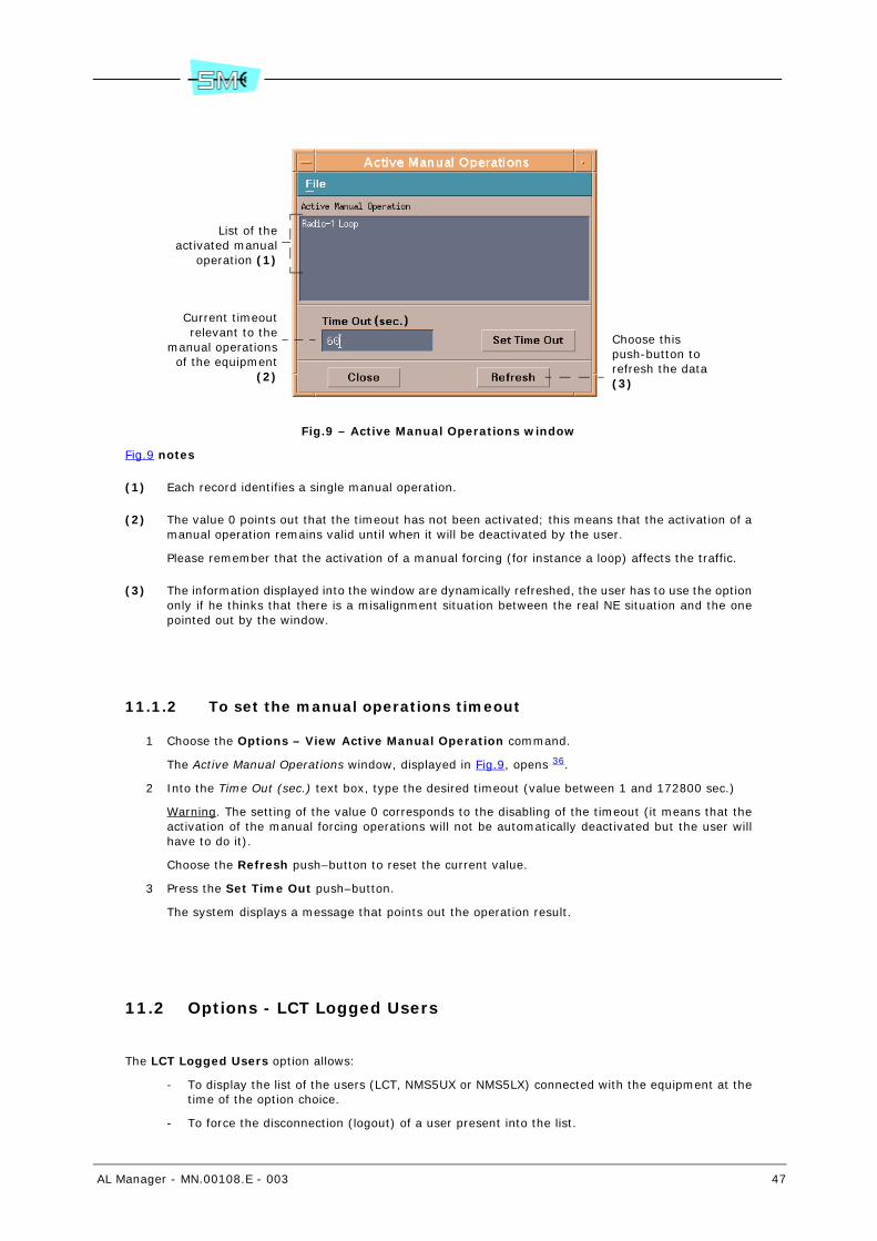
AL Manager - MN.00108.E - 003 47
Fig.9 – Active Manual Operations window
Fig.9 notes
(1) Each record identifies a single manual operation.
(2) The value 0 points out that the timeout has not been activated; this means that the activation of amanual operation remains valid until when it will be deactivated by the user.
Please remember that the activation of a manual forcing (for instance a loop) affects the traffic.
(3) The information displayed into the window are dynamically refreshed, the user has to use the optiononly if he thinks that there is a misalignment situation between the real NE situation and the onepointed out by the window.
11.1.2 To set the manual operations timeout
1 Choose the Options – View Active Manual Operation command.
The Active Manual Operations window, displayed in Fig.9, opens 36.
2 Into the Time Out (sec.) text box, type the desired timeout (value between 1 and 172800 sec.)
Warning. The setting of the value 0 corresponds to the disabling of the timeout (it means that theactivation of the manual forcing operations will not be automatically deactivated but the user willhave to do it).
Choose the Refresh push–button to reset the current value.
3 Press the Set Time Out push–button.
The system displays a message that points out the operation result.
11.2 Options - LCT Logged Users
The LCT Logged Users option allows:
- To display the list of the users (LCT, NMS5UX or NMS5LX) connected with the equipment at thetime of the option choice.
- To force the disconnection (logout) of a user present into the list.
List of theactivated manual
operation (1)
Current timeoutrelevant to the
manual operationsof the equipment
(2)
Choose thispush-button torefresh the data (3)
48 AL Manager - MN.00108.E - 003
Warning. If it is forced the logout of a NMS5UX or NMS5LX user, the supervisory system auto-matically executes the reset of the user connection.
Warning. The above described operations are reported into the NMS5UX or NMS5LX user manual.
11.3 Options - LCT Equipment Users
The LCT Equipment Users option allows:
- To display the LCT user list 37 of the NE.
- To add a new LCT user into the list.
- To change the characteristics of the LCT users present into the list.
- To remove a LCT user from the list.
Warning. The above described operations are reported into the NMS5UX or NMS5LX user manual.
11.4 Options – View Acknowledge Status
The View Acknowledge Status option allows checking the acknowledge status (par. 11.4.1) of the fol-lowing signals:
- Alarm (current and/or into the alarm history).
- Presence of the LCT program in Configuration mode.
- Operation of Configuration Upload 38 not correctly executed.
11.4.1 To check the acknowledge status of the alarms, LCT presence and Configuration Upload failed
1 Choose the Options – View Acknowledge Status command.
The Acknowledge Status window, displayed in Fig.10, opens.
37 Each AL equipment is provided with a user list. Each user of such a list can be connected with the LCTprogram. The user list is stored into the main controller of the equipment.
38 More detailed information concerning the Configuration Upload option are reported into the NMS5UXor NMS5LX user manual.

AL Manager - MN.00108.E - 003 49
Fig.10 – Acknowledge Status window
Fig.10 notes
(1) If the box is:
- Activated ( ), it is present, for the NE under examination, at least a not acknowledged alarm(current and/or into the alarm history).
It is possible to acknowledge an alarm by means of the commands present into the CurrentAlarms Browser (par. 10.1) and Alarm History Browser (par. 10.2) windows.
- Deactivated, all the possible alarms has been acknowledged.
(2) If the box is:
- Activated ( ), from the last time that it has been opened the Radio PDH-AL: Equipment win-dow for the NE under examination, the LCT program has been connected to the NE at leastone time in Configuration mode.
- Deactivated, from the last time that it has been opened the Radio PDH-AL: Equipment win-dow, the LCT program has not been connected to the NE in Configuration mode.
(3) If the box is:
- Activated ( ), the last Configuration Upload operation is failed.
The signal is automatically acknowledged at the first Configuration Upload operation correct-ly executed.
Warning. This condition is pointed out also by means of a Warning box into the Radio PDH-AL: Equipment window.
- Deactivated, the last Configuration Upload operation has been successfully executed.
Equipmenttype
Equipmentphysical address
Equipmentlogical address
Acknowledge status of the alarms(1)
LCT presence in Configuration mode (2)
Configuration Upload operation not correctly executed (3)

50 AL Manager - MN.00108.E - 003
12 MAINTENANCE (MENU)
The Maintenance menu contains the following options:
- Radio Switch (par. 12.1), it displays/changes the parameters relevant to the switching and pref-erential branch.
Warning. The command is available only for the equipment in configuration 1+1.
- Radio Branch x Loop (par. 12.2), it displays/changes the status of the base band loops (line sideand inner side).
12.1 Maintenance - Radio Switch
The Radio Switch command allows to check/change:
- Management of the switching (service/reserve) at reception (Rx Forced Switch) (par. 12.1.1)
- Management of the switching (service/reserve) at transmission (Tx Forced Switch) 39 (par. 12.1.2)
- Preferential branch management for the service at reception (Rx Preferential) (par. 12.1.3)
- Preferential branch management for the service at transmission (Tx Preferential) 39 (par. 12.1.4)
- Wait Time parameter 40 (par. 12.1.5)
- Forcing the switch on the preferential branch without waiting for the Wait Time period expiration(par. 12.1.6)
Warning. The command is available only for the equipment in configuration 1+1.
12.1.1 To check/change the management of the switching in reception (Rx Forced Switch)
1 Select the Maintenance - Radio Switch command.
The Radio PDH-AL: Unit – Radio Switch window opens (refer to Fig.11).
The Rx Forced Switch box displays the management of the switching in reception:
- auto, the switching is automatically managed according to the presence of the alarms (nor-mal functioning mode of the equipment).
- branch-1, the equipment is forced to use the branch 1 for the service.
- branch-2, the equipment is forced to use the branch 2 for the service.
39 Tx Preferential and Tx Forced Switch parameters are available only for the equipment in isofrequentialconfiguration 1+1. For the heterofrequential configuration 1+1, the parameters are not available becausethe two branches (1 and 2) transmit at the same time because the selection of the signal is executed atreception.
40 It is the time that the controller keep the service on not preferential branch before coming back to thepreferential branch. In this way the controller doesn’t continuously switch between the branches in presentof fleeting alarms
Warning. The setting of the Wait Time parameter is meaningful only for the preferential transmitter.
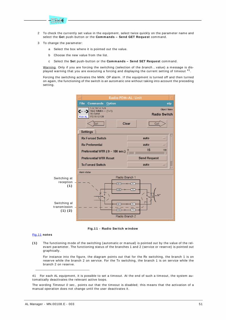
AL Manager - MN.00108.E - 003 51
2 To check the currently set value in the equipment, select twice quickly on the parameter name andselect the Get push-button or the Commands – Send GET Request command.
3 To change the parameter:
a Select the box where it is pointed out the value.
b Choose the new value from the list.
c Select the Set push-button or the Commands – Send SET Request command.
Warning. Only if you are forcing the switching (selection of the branch… value) a message is dis-played warning that you are executing a forcing and displaying the current setting of timeout 41.
Forcing the switching activates the MAN. OP alarm. If the equipment is turned off and then turnedon again, the functioning of the switch is an automatic one without taking into account the precedingsetting.
Fig.11 - Radio Switch window
Fig.11 notes
(1) The functioning mode of the switching (automatic or manual) is pointed out by the value of the rel-evant parameter. The functioning status of the branches 1 and 2 (service or reserve) is pointed outgraphically.
For instance into the figure, the diagram points out that for the Rx switching, the branch 1 is onreserve while the branch 2 on service. For the Tx switching, the branch 1 is on service while thebranch 2 on reserve.
41 For each AL equipment, it is possible to set a timeout. At the end of such a timeout, the system au-tomatically deactivates the relevant active loops.
The wording Timeout 0 sec., points out that the timeout is disabled; this means that the activation of amanual operation does not change until the user deactivates it.
Switching atreception
(1)
Switching altransmission
(1) (2)

52 AL Manager - MN.00108.E - 003
The functioning status of the branches 1 and 2 is pointed out also in the equipment view area of theRadio PDH–AL: Equipment window (par. 3.5).
(2) This figure, refers to an equipment with 1+1 Hot Standby configuration. For the equipment in 1+1Frequency Diversity configuration, the Tx switching is not displayed graphically, because the twobranches transmit at the same time though the signal selection is executed at reception.
12.1.2 To check/change the management of the switching in transmis-sion (Tx Forced Switch)
1 Select the Maintenance - Radio Switch command.
The Radio PDH-AL: Unit – Radio Switch window opens (refer to Fig.11).
The Tx Forced Switch 39 box displays the management of the switching in transmission:
- auto, the switching is automatically managed according to the presence of the alarms (nor-mal functioning mode of the equipment).
- branch-1, the equipment is forced to use the branch 1 for the service.
- branch-2, the equipment is forced to use the branch 2 for the service.
2 To check the currently set value in the equipment, select twice quickly on the parameter name andselect the Get push-button or the Commands – Send GET Request command.
3 To change the parameter:
a Select the box where it is pointed out the value.
b Choose the new value from the list.
c Select the Set push-button or the Commands – Send SET Request command.
Warning. Only if you are forcing the switching (selection of the branch… value) a message is dis-played warning that you are executing a forcing and displaying the current setting of timeout 41.
Forcing the switching activates the MAN. OP alarm. If the equipment is turned off and then turnedon again, the functioning of the switch is an automatic one without taking into account the precedingsetting.
12.1.3 To check/change the management of the preferential branch in reception (Rx Preferential)
1 Select the Maintenance - Radio Switch command.
The Radio PDH-AL: Unit – Radio Switch window opens (refer to Fig.11).
The Rx Preferential box displays the management of the preferential branch in reception:
- auto, without the presence of alarms (that cause the switching), the equipment does not usea branch in a preferential manner with respect to the other one.
- branch-1, without the presence of alarms (that cause the switching), the equipment use thebranch 1.
- branch-2, without the presence of alarms (that cause the switching), the equipment use thebranch 2.
2 To check the currently set value in the equipment, select twice quickly on the parameter name andselect the Get push-button or the Commands – Send GET Request command.
3 To change the parameter:
a Select the box where it is pointed out the value.
b Choose the new value from the list.
c Select the Set push-button or the Commands – Send SET Request command.
AL Manager - MN.00108.E - 003 53
12.1.4 To check/change the management of the preferential branch in transmission (Tx Preferential)
1 Select the Maintenance - Radio Switch command.
The Radio PDH-AL: Unit – Radio Switch window opens (refer to Fig.11).
The Tx Preferential 39 box displays the management of the preferential branch in transmission:
- auto, without the presence of alarms (that cause the switching), the equipment does not usea branch in a preferential manner with respect to the other one.
- branch-1, without the presence of alarms (that cause the switching), the equipment use thebranch 1.
- branch-2, without the presence of alarms (that cause the switching), the equipment use thebranch 2.
2 To check the currently set value in the equipment, select twice quickly on the parameter name andselect the Get push-button or the Commands – Send GET Request command.
3 To change the parameter:
a Select the box where it is pointed out the value.
b Choose the new value from the list.
c Select the Set push-button or the Commands – Send SET Request command.
12.1.5 To check/change the Wait Time parameter
Warning. The setting of the Wait Time parameter is meaningful only for the preferential transmitter.
1 Select the Maintenance - Radio Switch command.
The Radio PDH-AL: Unit – Radio Switch window opens (refer to Fig.11).
The Preferential WTR (0-180 sec) box, points out the value of the Wait Time parameter 40.
2 To check the currently set value in the equipment, select twice quickly on the parameter name andselect the Get push-button or the Commands – Send GET Request command.
3 To change the parameter:
a Move the Preferential WTR (0-180 sec) cursor to the new value.
Warning. The selection of the value 0 deactivates the management of the RADIO SWITCHReserve Radio Branch Selected in Revertive Mode.
b Select the Set push-button or the Commands – Send SET Request command.
12.1.6 To force the switch on the preferential branch without waiting for the Wait Time
Warning. The forcing of the switch is meaningful only for the preferential transmitter.
1 Select the Maintenance - Radio Switch command.
The Radio PDH-AL: Unit – Radio Switch window opens (refer to Fig.11).
2 Select the Send Request push-button.
A confirmation window opens.
3 Select the Ok push-button.

54 AL Manager - MN.00108.E - 003
12.2 Maintenance - Radio Branch x Loop
The Radio Branch x Loop command allows to check/change the status of loops (par. 12.2.1).
Warning. For the equipment in configuration 1+0, it is present the Radio Branch 1 Loop command. Forthe equipment in configuration 1+1, there are present the Radio Branch 1 Loop (loops branch 1) andRadio Branch 2 Loop (loops branch 2) commands. For the equipment in Terminal 16x2 East-West type,there are present the Radio Branch East Loop (loops branch east) and Radio Branch West Loop (loopsbranch west) commands.
12.2.1 To verify/modify the status of loops
Warning. The activation of a loop compromises the traffic. It is advisable, before activating such a loop, tocheck that it has been set the timeout 41 relevant to the equipment where the loop has to be activated; onthe contrary, the loop will remain activated until when the user will deactivate it or the equipment will beturned off/turned on or reset.
1 Select the Maintenance - Radio Branch x Loop command.
The Radio PDH-AL: Unit – Radio Branch Loop window opens (refer to Fig.12).
The Loop Enable box displays the loop status:
- Loop Off, no loop is active.
- RF Loop On-Rem Tx Off, IDU Loop, Base Band Loop, the specific loop is active.
2 To check the currently set value in the equipment, select twice quickly on the parameter name andselect the Get push-button or the Commands – Send GET Request command.
3 To change the parameter:
a Select the box where it is pointed out the value.
b Choose the new value from the list.
c Select the Set push-button or the Commands – Send SET Request command.
Warning. Only if you are activating a loop, a message is displayed warning that you are executinga forcing and showing the current setting of the timeout 41.
The activation of a loop activates the MAN. OP alarm. If the equipment is switched off and, then,switched on, the loop results inactive, independently from the previous setting.
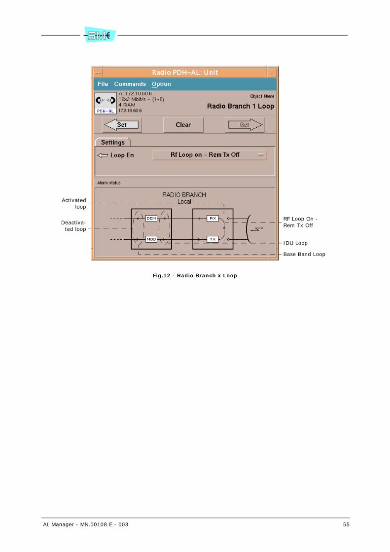
AL Manager - MN.00108.E - 003 55
Fig.12 - Radio Branch x Loop
Activatedloop
Deactiva-ted loop
Base Band Loop
IDU Loop
RF Loop On - Rem Tx Off
56 AL Manager - MN.00108.E - 003
13 HELP (MENU)
The Help menu contains the following commands:
- On Usage (par. 13.1). AL Manager user manual.
13.1 Help – On Usage
The On Usage command displays the present AL Manager user manual.
The manual is in English and in PDF format. On the selection of the command, the Acrobat Reader browseris automatically opened.
To browse in the manual, use the summary items and the hyper textual links.

AL Manager - MN.00108.E - 003 57
14 PRBS (PUSH-BUTTON)
The PRBS push-button allows:
- To verify the PRBS measure status 42 (par. 14.1)
- To activate/reset the PRBS measure (par. 14.2)
- To deactivate the PRBS measure (par. 14.3)
- To verify/modify the type of PRBS pattern used for the measure (par. 14.4)
- To verify/modify the signal used for the measure (par. 14.5)
14.1 To verify the PRBS measure status
1 Select the PRBS push-button.
The Radio PDH-AL: Unit – PRBS window, displayed in Fig.13 opens.
The PRBS Start box displays the measure status:
- Start Reset, P.R.B.S. measure is active.
- Stop, P.R.B.S. measure is deactivated.
2 To check the currently set value in the equipment, select twice quickly on the parameter name andselect the Get push-button or the Commands – Send GET Request command.
42 P.R.B.S. (Pseudo Random Binary Sequence). Control functionality, integrated in the base band, thatallows inserting a P.R.B.S. data stream on a 2Mbit/s stream or on a service data channel at 64Kbit/s fortest operation and measurement of the error rate.
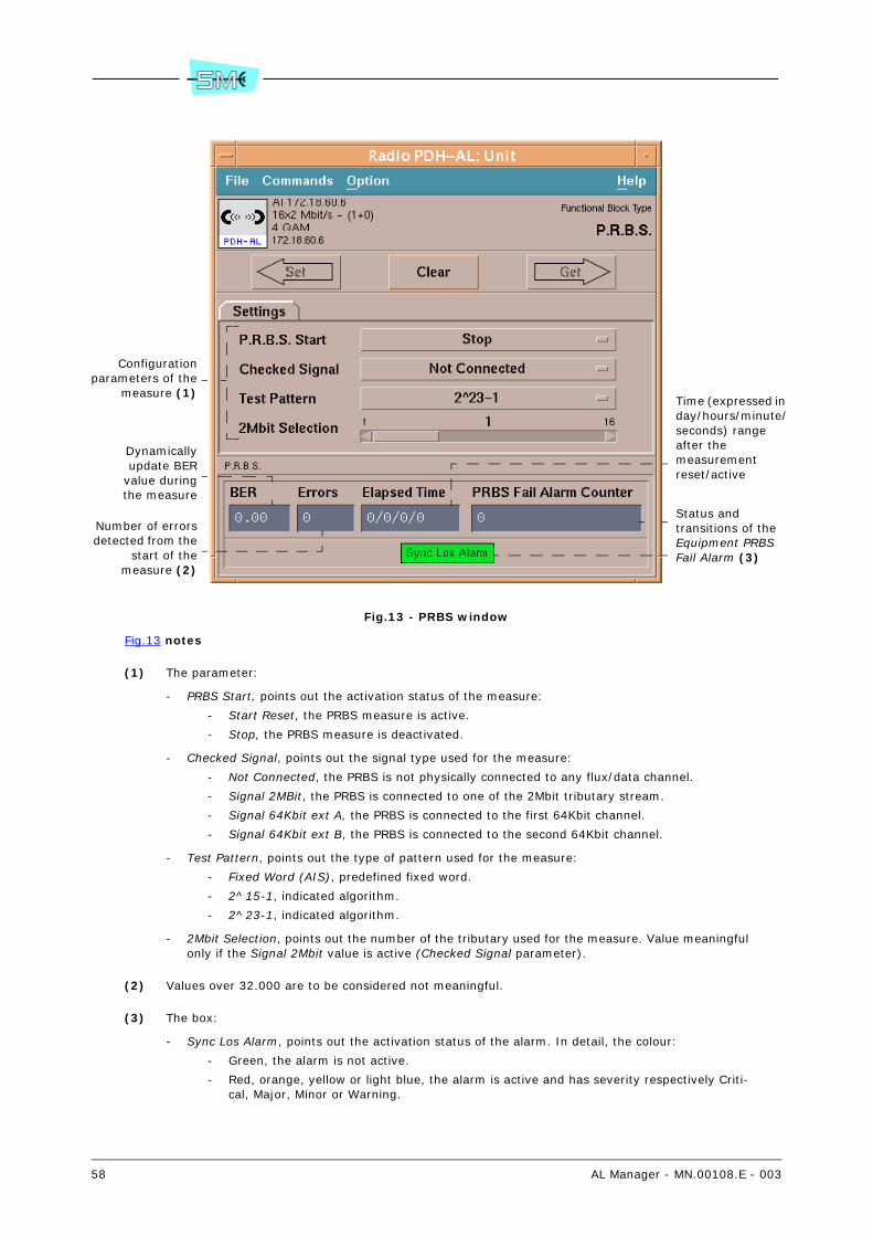
58 AL Manager - MN.00108.E - 003
Fig.13 - PRBS window
Fig.13 notes
(1) The parameter:
- PRBS Start, points out the activation status of the measure:
- Start Reset, the PRBS measure is active.
- Stop, the PRBS measure is deactivated.
- Checked Signal, points out the signal type used for the measure:
- Not Connected, the PRBS is not physically connected to any flux/data channel.
- Signal 2MBit, the PRBS is connected to one of the 2Mbit tributary stream.
- Signal 64Kbit ext A, the PRBS is connected to the first 64Kbit channel.
- Signal 64Kbit ext B, the PRBS is connected to the second 64Kbit channel.
- Test Pattern, points out the type of pattern used for the measure:
- Fixed Word (AIS), predefined fixed word.
- 2^15-1, indicated algorithm.
- 2^23-1, indicated algorithm.
- 2Mbit Selection, points out the number of the tributary used for the measure. Value meaningfulonly if the Signal 2Mbit value is active (Checked Signal parameter).
(2) Values over 32.000 are to be considered not meaningful.
(3) The box:
- Sync Los Alarm, points out the activation status of the alarm. In detail, the colour:
- Green, the alarm is not active.
- Red, orange, yellow or light blue, the alarm is active and has severity respectively Criti-cal, Major, Minor or Warning.
Dynamicallyupdate BER
value duringthe measure
Number of errorsdetected from the
start of themeasure (2)
Time (expressed in day/hours/minute/seconds) rangeafter themeasurementreset/active
Status andtransitions of theEquipment PRBS Fail Alarm (3)
Configurationparameters of the
measure (1)

AL Manager - MN.00108.E - 003 59
- PRBS Fail Alarm Counter, indicates the number of times that the Sync Los Alarm activated fromthe start of the measure.
14.2 To activate/reset the PRBS measure
1 Select the PRBS push-button.
The Radio PDH-AL: Unit – PRBS window opens (refer to Fig.13).
2 Select the PRBS Start box.
3 Choose the Start Reset value.
4 Select the Set push-button or the Commands – Send SET Request command.
The measure will be active until the user does not stop it.
14.3 To deactivate the PRBS measure
1 Select the PRBS push-button.
The Radio PDH-AL: Unit – PRBS window opens (refer to Fig.13).
2 Select the PRBS Start box.
3 Choose the Stop value.
4 Select the Set push-button or the Commands – Send SET Request command.
14.4 To verify/modify the type of PRBS pattern used for the meas-ure
1 Select the PRBS push-button.
The Radio PDH-AL: Unit – PRBS window opens (refer to Fig.13).
The Test Pattern box displays the type of PRBS pattern used for the measure:
- Fixed Word (AIS), a predefined fixed word is used for the measure.
- 2^15-1, the indicated algorithm is used for the measure.
- 2^23-1, the indicated algorithm is used for the measure.
2 To check the currently set value in the equipment, select twice quickly on the parameter name andselect the Get push-button or the Commands – Send GET Request command.
3 To change the parameter:
a Select the box where it is pointed out the value.
b Choose the new value from the list.
c Select the Set push-button or the Commands – Send SET Request command.
60 AL Manager - MN.00108.E - 003
14.5 To verify/modify the signal used for the measure
1 Select the PRBS push-button.
The Radio PDH-AL: Unit – PRBS window opens (refer to Fig.13).
The Checked Signal box displays the used signal for the measure:
- Not Connected, the PRBS is not physically connected to any flux/data channel.
- Signal 2MBit, the PRBS is connected to one of the 2Mbit tributary stream.
- Signal 64Kbit ext A, the PRBS is connected to the first 64Kbit channel.
- Signal 64Kbit ext B, the PRBS is connected to the second 64Kbit channel.
2 To check the currently set value in the equipment, select twice quickly on the parameter name andselect the Get push-button or the Commands – Send GET Request command.
3 To change the parameter:
a Select the box where it is pointed out the value 43.
b Choose the new value from the list.
Warning. The setting of the signal used for the measure determinates also the connector(tributary, 64Kbit ext A or 64Kbit ext B), which a measurement instrument can be connectedto for the control of the error rate by means of the PRBS functionality.
The PRBS replaces the traffic on the channel where it is connected.
c ONLY if the Signal 2Mbit push-button is selected, set the number of the tributary streammoving the 2MBbit Selection cursor on the wished value.
d Select the Set push-button or the Commands – Send SET Request command.
Warning. Only if you are setting a valid signal (selection of the Signal… value) a message is dis-played warning that you are executing a forcing and displaying the current setting of timeout 41.
The choice of a signal activates the MAN. OP alarm. If the equipment is switched off and, then,switched on the forcing is inactive independently from the previous setting.
43 For the equipment that have not the data channels, the relevant value are not available.
AL Manager - MN.00108.E - 003 61
15 USER INPUT (PUSH-BUTTON)
The User Input push-button allows to verify/modify the status and configuration parameters of the localuser inputs 44 and remote user inputs 45 available for the equipment:
- To check the user input status (local/remote) (par. 15.1)
- To check/change the name of the user input (local/remote) (par. 15.2)
- To check/change the activated condition of the local user input (par. 15.3)
- To enable/disable the user input (local/remote) alarm or the forwarding of the trap to the su-pervisory system (par. 15.4). With details, it is possible to execute the following operations:
- To disable the user input alarm; in this case the detection (or the reset) of the alarm isneither stored into the NE controller nor communicated to the supervisory system: as ifsuch an alarm has never occurred.
- To disable the forwarding of the trap; in this case the detection (or the reset) of the alarmis stored into the NE controller but it is not communicated to the supervisory system 46.
- To enable the user input alarm and the forwarding of the trap; in this case the detection(or the reset) of the alarm is stored into the NE controller and it is also communicated tothe supervisory system (by means of the forwarding of the relevant trap).
- To check/change the seriousness level coupled with the user input (local/remote) (par. 15.4)
Warning. The changing of the seriousness level coupled with an user input alarm is alocal operation and involves the NE under examination only.
The so set seriousness level of the user input alarm characterizes the alarm when it is storedinto the NE controller, displayed by the LCT program and by the NMS5UX or NMS5LX supervisorysystem.
15.1 To check the user input status (local/remote)
1 Select the User Input push-button.
It is displayed the Radio PDH-AL - User Input window.
The window points out the status of the local and remote user input as shown in Fig.14.
44 The wording local user input identifies a signal that enters into the local equipment by means of theuser connector. Its (programmable) open or closed status is reported as an alarm or status event.
45 The wording remote user input identifies a signal in input to the remote equipment, through the userconnector and that is returned in output from the local equipment through relays contacts (user output)or user connectors.
46 Warning. If the system forwards a Configuration Upload one (refer to NMS5UX or NMS5LX manual)to the NE under examination, the system will acquire also the alarm signals with the relevant trap forward-ing disabled.
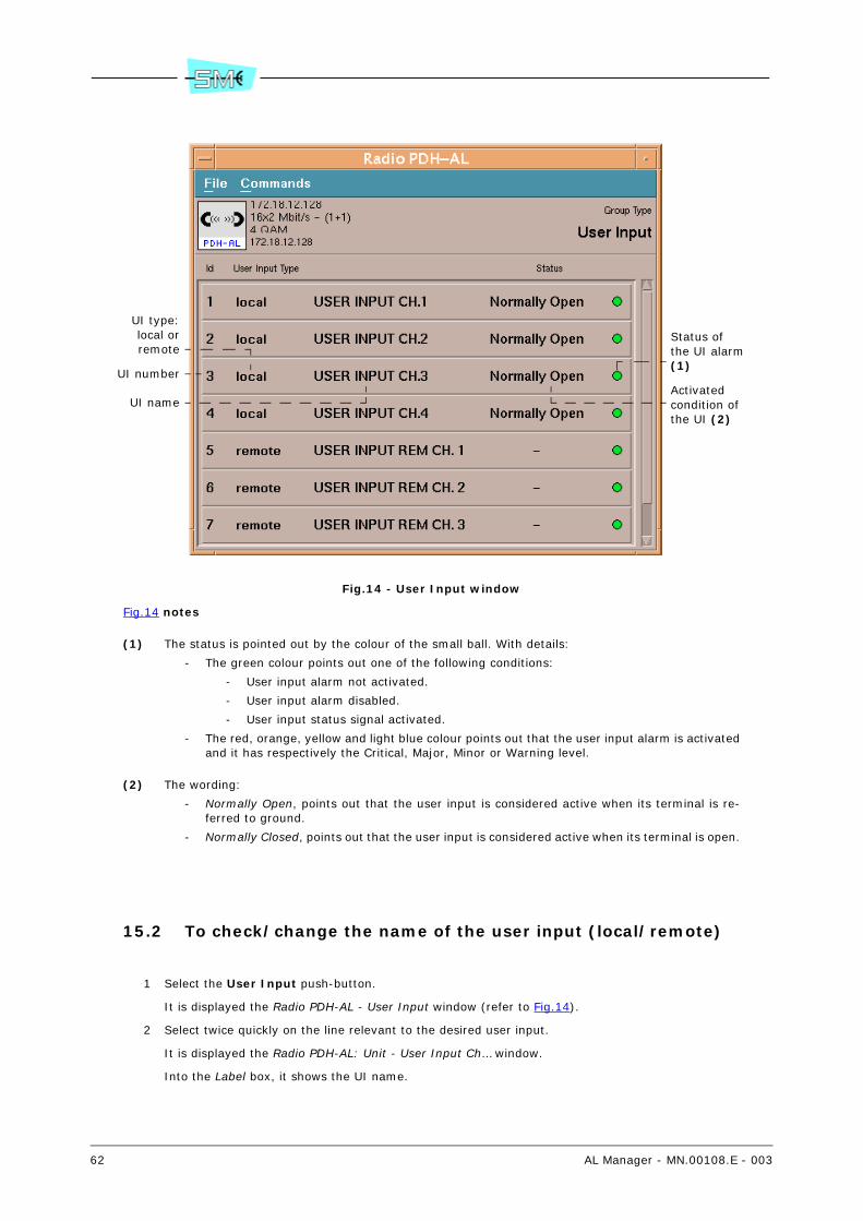
62 AL Manager - MN.00108.E - 003
Fig.14 - User Input window
Fig.14 notes
(1) The status is pointed out by the colour of the small ball. With details:
- The green colour points out one of the following conditions:
- User input alarm not activated.
- User input alarm disabled.
- User input status signal activated.
- The red, orange, yellow and light blue colour points out that the user input alarm is activatedand it has respectively the Critical, Major, Minor or Warning level.
(2) The wording:
- Normally Open, points out that the user input is considered active when its terminal is re-ferred to ground.
- Normally Closed, points out that the user input is considered active when its terminal is open.
15.2 To check/change the name of the user input (local/remote)
1 Select the User Input push-button.
It is displayed the Radio PDH-AL - User Input window (refer to Fig.14).
2 Select twice quickly on the line relevant to the desired user input.
It is displayed the Radio PDH-AL: Unit - User Input Ch… window.
Into the Label box, it shows the UI name.
UI type:local orremote
UI number
UI name
Status ofthe UI alarm (1)
Activated condition of the UI (2)
AL Manager - MN.00108.E - 003 63
3 To check the currently set value in the equipment, select twice quickly on the parameter name andselect the Get push-button or the Commands – Send GET Request command.
4 To change the parameter:
a Type into the box an alphanumeric string with a minimum of 1 and a maximum of 31 char-acters.
b Select the Set push-button or the Commands – Send SET Request command.
15.3 To check/change the activated condition of the local user in-put
Warning. The operation is available only for the local user input.
1 Select the User Input push-button.
It is displayed the Radio PDH-AL - User Input window (refer to Fig.14).
2 Select twice quickly on the line relevant to the desired local user input.
It is displayed the Radio PDH-AL: Unit - User Input Ch… window.
Into the Active State box, it shows the activated condition of the user input:
- Normally Open, the UI will be considered active (creation of the alarm event) when its ter-minal is referred to ground.
- Normally Closed, the UI will be considered active (creation of the alarm event) when its ter-minal is open.
3 To check the currently set value in the equipment, select twice quickly on the parameter name andselect the Get push-button or the Commands – Send GET Request command.
4 To change the parameter:
a Select the box where it is pointed out the value.
b Choose the new value from the list.
c Select the Set push-button or the Commands – Send SET Request command.
15.4 To enable/disable the UI (local/remote) alarm or the forward-ing of the trap to the supervisory system and to define the se-riousness level of an UI (local/remote)
1 Select the User Input push-button.
It is displayed the Radio PDH-AL - User Input window (refer to Fig.14).
2 Select twice quickly on the line relevant to the desired user input.
It is displayed the Radio PDH-AL: Unit - User Input Ch… window.
Into the Severity Code box, it shows the status of the user input alarm (enabled/disabled), statusof the forwarding of the relevant trap (enabled/disabled) and seriousness level of the user input(UI). If the:
- Critical Trap Disable, Major Trap Disable, Minor Trap Disable or Warning Trap Disable valueis active:
- The alarm created by the activation of the UI is enabled.
- The forwarding of the relevant trap is disabled.

64 AL Manager - MN.00108.E - 003
- The signal at input of the UI is coupled with a seriousness level equivalent to an alarmrespectively with Critical, Major, Minor, Warning level.
- Status Trap Disable value is active:
- The alarm created by the activation of the UI is enabled.
- The forwarding of the relevant trap is disabled.
- The signal at input of the UI is coupled with a seriousness level equivalent to a statussignal.
- Critical Trap Enable, Major Trap Enable, Minor Trap Enable or Warning Trap Enable value isactive:
- The alarm created by the activation of the UI and the forwarding of the relevant trapis enabled.
- The signal at input of the UI is coupled with a seriousness level equivalent to an alarmrespectively with Critical, Major, Minor, Warning level.
- Status Trap Enable value is active:
- The alarm created by the activation of the UI and the forwarding of the relevant trapis enabled.
- The signal at input of the UI is coupled with a seriousness level equivalent to a statussignal.
- Disable value is active, the alarm created by the activation of the UI is disabled 47.
3 To check the currently set value in the equipment, select twice quickly on the parameter name andselect the Get push-button or the Commands – Send GET Request command.
4 To change the parameter:
a Select the box where it is pointed out the value.
b Choose the new value from the list.
c Select the Set push-button or the Commands – Send SET Request command.
47 The disabling of an alarm/forwarding of a trap is pointed out, into the Radio PDH-AL: Equipment win-dow, by means of a warning box (refer to Fig.3).
AL Manager - MN.00108.E - 003 65
16 USER OUTPUT (PUSH-BUTTON)
The User Output push-button allows to verify/modify the status and configuration parameters of the useroutputs 48 (UO) of the equipment:
- To check the user output status (par. 16.1)
- To check/change the name of the user output (par. 16.2)
- To check/change the functioning mode of the user output relay contacts (par. 16.3)
- To couple with the user output one of the following signals (par. 16.4):
- Group of alarms, which the same severity level has been assigned to, and/or group ofalarms of local and/or remote (IDU/ODU) equipment.
- User input (local and/or remote).
- To enabled the forced activation of the relays contacts from operator (par. 16.5)
- To force the activation of the relay contacts relevant to a user output (if it has been previouslyenabled) (par. 16.6)
- To remove the force activation of the relay contacts relevant to a user output (par. 16.7)
- To force the download of the default name of the user output (par. 16.8).
This operation consists in executing the download of the default names of the user output fromthe supervision system to the equipment.
16.1 To check the user output status
1 Select the User Output push-button.
It is displayed the Radio PDH-AL – User Output window.
The window points out the status of the user output as shown in Fig.15.
Select the Commands - Refresh User Output Status command to refresh the date present intothe window.
48 The user output wording identifies a signal that the equipment makes available on rack as relay con-tact.

66 AL Manager - MN.00108.E - 003
Fig.15 - User Output window
Fig.15 notes
(1) The wording:
- Not active, the UO has not been activated.
- Active, UO has been activated (activated relay contacts).
(2) The wording:
- Forced by Operator, points out a double condition. With details:
- If the user output is not activated (refer to Status column), it means that the UO isenabled for the activation forcing executed by the user.
- If the user output is activated (refer to Status column), it means that the UO has beenactivated after the forcing executed by the user.
- Unmapped, indicates that no signal is associated to UO.
- Mapped, indicates that one or more signals are associated to UO (group of alarms and/oruser input).
In order to verify the detail of the signals double click the UO.
16.2 To check/change the name of the user output
1 Select the User Output push-button.
It is displayed the Radio PDH-AL – User Output window (refer to Fig.15).
2 Select twice quickly on the line relevant to the desired user output.
It is displayed the Radio PDH-AL: Unit - User Output Ch… window.
Into the Label box, it shows the UO name.
3 To check the currently set value in the equipment, select twice quickly on the parameter name andselect the Get push-button or the Commands – Send GET Request command.
4 To change the parameter:
a Type into the box an alphanumeric string with a minimum of 1 and a maximum of 31 char-acters.
b Select the Set push-button or the Commands – Send SET Request command.
UO number
UO name
UO status (1)
Signalcoupled with the UO (2)
AL Manager - MN.00108.E - 003 67
16.3 To check/change the functioning mode of the user output re-lay contacts
1 Select the User Output push-button.
It is displayed the Radio PDH-AL – User Output window (refer to Fig.15).
2 Select twice quickly on the line relevant to the desired user output.
It is displayed the Radio PDH-AL: Unit - User Output Ch… window.
Into the Active State box, it shows the functioning mode of the user output relay contacts. If activethe value:
- Open, with absence of signal (alarm or user input or manual forcing), the relays contacts areclosed (rest condition), with presence of signal the contacts are open.
- Closed, with absence of signal (alarm or user input or manual forcing), the relays contactsare open (rest condition), with presence of signal the contacts are closed.
3 To check the currently set value in the equipment, select twice quickly on the parameter name andselect the Get push-button or the Commands – Send GET Request command.
4 To change the parameter:
a Select the box where it is pointed out the value.
b Choose the new value from the list.
c Select the Set push-button or the Commands – Send SET Request command.
16.4 To couple with the user output a signal (alarms or UI)
1 Select the User Output push-button.
It is displayed the Radio PDH-AL – User Output window (refer to Fig.15).
2 Select twice quickly on the line relevant to the desired user output.
It is displayed the Radio PDH-AL: Unit - User Output Ch… window.
The Internal Status box shows the signal coupled with the user output:
- Forced by Operator, the UO is enabled for the forcing executed by the user.
- Unmapped, no signal is associated to UO.
- Mapped, one or more signals are associated to UO (group of alarms and/or user input).
3 To check the currently set value in the equipment, select twice quickly on the parameter name andselect the Get push-button or the Commands – Send GET Request command.
4 To couple with the user output a signal (alarms or UI):
a Select the box that points out the value.
The system displays the User Output Properties window.
b Choose one of the Linked to Map push–button
c In the areas below (Group/Link) select the group and then the signals you wish to associateto UO (refer to Fig.16).
The selection of a signal in the Link area is pointed out by the X next to the value.
Warning. It is possible to assign more signals to each user output. Furthermore, it is possibleto associate the same signal or signals to different user outputs.
d Choose the Ok push–button.
e Select the Set push-button or the Commands – Send SET Request command.
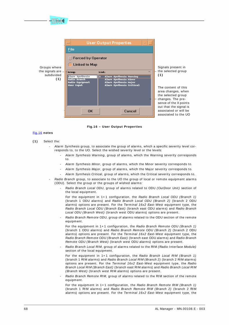
68 AL Manager - MN.00108.E - 003
Fig.16 – User Output Properties
Fig.16 notes
(1) Select the:
- Alarm Synthesis group, to associate the group of alarms, which a specific severity level cor-responds to, to the UO. Select the wished severity level or the levels:
- Alarm Synthesis Warning, group of alarms, which the Warning severity correspondsto.
- Alarm Synthesis Minor, group of alarms, which the Minor severity corresponds to.
- Alarm Synthesis Major, group of alarms, which the Major severity corresponds to.
- Alarm Synthesis Critical, group of alarms, which the Critical severity corresponds to.
- Radio Branch group, to associate to the UO the group of local or remote equipment alarms(ODU). Select the group or the groups of wished alarms:
- Radio Branch Local ODU, group of alarms related to ODU (OutDoor Unit) section ofthe local equipment.
For the equipment in 1+1 configuration, the Radio Branch Local ODU (Branch 1)(branch 1 ODU alarms) and Radio Branch Local ODU (Branch 2) (branch 2 ODUalarms) options are present. For the Terminal 16x2 East-West equipment type, theRadio Branch Local ODU (Branch East) (branch east ODU alarms) and Radio BranchLocal ODU (Branch West) (branch west ODU alarms) options are present.
- Radio Branch Remote ODU, group of alarms related to the ODU section of the remoteequipment.
For the equipment in 1+1 configuration, the Radio Branch Remote ODU (Branch 1)(branch 1 ODU alarms) and Radio Branch Remote ODU (Branch 2) (branch 2 ODUalarms) options are present. For the Terminal 16x2 East-West equipment type, theRadio Branch Remote ODU (Branch East) (branch east ODU alarms) and Radio BranchRemote ODU (Branch West) (branch west ODU alarms) options are present.
- Radio Branch Local RIM, group of alarms related to the RIM (Radio Interface Module)section of the local equipment.
For the equipment in 1+1 configuration, the Radio Branch Local RIM (Branch 1)(branch 1 RIM alarms) and Radio Branch Local RIM (Branch 2) (branch 2 RIM alarms)options are present. For the Terminal 16x2 East-West equipment type, the RadioBranch Local RIM (Branch East) (branch east RIM alarms) and Radio Branch Local RIM(Branch West) (branch west RIM alarms) options are present.
- Radio Branch Remote RIM, group of alarms related to the RIM section of the remoteequipment.
For the equipment in 1+1 configuration, the Radio Branch Remote RIM (Branch 1)(branch 1 RIM alarms) and Radio Branch Remote RIM (Branch 2) (branch 2 RIMalarms) options are present. For the Terminal 16x2 East-West equipment type, the
Groups wherethe signals are
subdivided(1)
Signals present in the selected group (1)
The content of this area changes, when the selected group changes. The pre-sence of the X points out that the signal is associated or will be associated to the UO
AL Manager - MN.00108.E - 003 69
Radio Branch Remote RIM (Branch East) (branch east RIM alarms) and Radio BranchRemote RIM (Branch West) (branch west RIM alarms) options are present.
- Radio Equipment group, to associated to the UO the group of local or remote equipmentalarms (IDU). Select the group or the groups of wished alarms:
- Radio Equipment Local LIM, group of alarms related to LIM (Line Interface Module)section of the local equipment.
For the Terminal 16x2 East-West equipment type, the Radio Equipment Local LIMEast (branch east LIM alarms) and Radio Equipment Local LIM West (branch west LIMalarms) options are present. For the equipment in 1+1 Full-Duplicated configuration,the Radio Equipment Local LIM Main (main LIM alarms) and Radio Equipment LocalLIM Reserve (secondary LIM alarms) options are present.
- Radio Equipment Remote LIM, group of alarms related to LIM section of the remoteequipment.
For the Terminal 16x2 East-West equipment type, the Radio Equipment Remote LIMEast (branch east LIM alarms) and Radio Equipment Remote LIM West (branch westLIM alarms) options are present. For the equipment in 1+1 Full-Duplicated configu-ration, the Radio Equipment Remote LIM Main (main LIM alarms) and Radio Equip-ment Remote LIM Reserve (secondary LIM alarms) options are present.
- User Input box, to associated to the user output one or more local (User Input …)and/or remote (User Input Rem …) user inputs. Select the wished user inputs.
16.5 To enabled the forced activation of the relays contacts from operator
1 Select the User Output push-button.
It is displayed the Radio PDH-AL – User Output window (refer to Fig.15).
2 Select twice quickly on the line relevant to the desired user output.
It is displayed the Radio PDH-AL: Unit - User Output Ch… window.
The Internal Status box shows the signal coupled with the user output:
- Forced by Operator, the UO is enabled for the forcing executed by the user.
- Unmapped, no signal is associated to UO.
- Mapped, one or more signals are associated to UO (group of alarms and/or user input).
3 To check the currently set value in the equipment, select twice quickly on the parameter name andselect the Get push-button or the Commands – Send GET Request command.
4 To enabled the forced activation of the relays contacts from operator:
a Select the box that points out the value.
The system displays the User Output Properties window (refer to Fig.16).
b Choose the Forced by Operator push–button.
c Choose the Ok push–button.
d Select the Set push-button or the Commands – Send SET Request command.
16.6 To force the activation of the relay contacts relevant to a user output
1 Select the User Output push-button.
It is displayed the Radio PDH-AL – User Output window (refer to Fig.15).
70 AL Manager - MN.00108.E - 003
2 Select twice quickly on the line relevant to the desired user output.
It is displayed the Radio PDH-AL: Unit - User Output Ch… window.
The Forced Operator Status box shows the status of the forcing executed by the user:
- Forced, the forcing executed by the user has been activated (then, it has been activated alsothe UO).
- Unforced, the forcing executed by the user has not been activated (then, it has not beenactivated also the UO).
Warning. This parameter is meaning only if the UO has been enabled for the forcing executed bythe user.
3 To check the currently set value in the equipment, select twice quickly on the parameter name andselect the Get push-button or the Commands – Send GET Request command.
4 To force the activation of the relay contacts:
a Select the box that points out the value.
b Choose the Forced value.
c Select the Set push-button or the Commands – Send SET Request command.
Warning. The UO will remain activated until the removal of the forcing.
16.7 To remove the force activation of the relay contacts relevant to a user output
1 Select the User Output push-button.
It is displayed the Radio PDH-AL – User Output window (refer to Fig.15).
2 Select twice quickly on the line relevant to the desired user output.
It is displayed the Radio PDH-AL: Unit - User Output Ch… window.
The Forced Operator Status box shows the status of the forcing executed by the user:
- Forced, the forcing executed by the user has been activated (then, it has been activated alsothe UO).
- Unforced, the forcing executed by the user has not been activated (then, it has not beenactivated also the UO).
Warning. This parameter is meaning only if the UO has been enabled for the forcing executed bythe user.
3 To check the currently set value in the equipment, select twice quickly on the parameter name andselect the Get push-button or the Commands – Send GET Request command.
4 To remove the force the activation of the relay contacts:
a Select the box that points out the value.
b Choose the Unforced value.
c Select the Set push-button or the Commands – Send SET Request command.
16.8 To force the download of the default name of the user output
1 Select the User Output push-button.
It is displayed the Radio PDH-AL – User Output window (refer to Fig.15).
AL Manager - MN.00108.E - 003 71
2 Select the Commands - Download Default Labels command.
A window for the confirmation opens.
3 Select the Ok push-button.
At the end of the operation, the Radio PDH-AL – User Output window closes.
72 AL Manager - MN.00108.E - 003
17 RADIO EQUIPMENT (PUSH-BUTTON)
The Radio Equipment push-button allows to verify/modify:
- Protection type of the local equipment (par. 17.1) (Configuration)
- Base band type of the local equipment (par. 17.2) (Base Band Configuration)
- Capacity of the local equipment (par. 17.3) (Local Capacity...) 49
- Capacity of the local and remote equipment (par. 17.4) (Link Capacity) 49
- Modulation of the local equipment (par. 17.5) (Local Modulation Type) 49
- Modulation of the local and remote equipment (par. 17.6) (Link Modulation Type) 49
- Connection identificative number of the local equipment (par. 17.7) (Local Link ID...) 49
- Connection identificative number of the local and remote equipment (par. 17.8) (Link ID) 49
- Threshold of the signal at reception, under which the related alarms are activated (par. 17.9)(Rx Signal Level Alarm Thresh) 49
- LBER alarm threshold (par. 17.10) (LBer Threshold) 49
- HBER alarm threshold (par. 17.11) (HBer Threshold) 49
- EWL alarm threshold (par. 17.12) (Early Warning Threshold) 49
- Using of the HBER alarm as switching and AIS insertion criterion at reception (par. 17.13) (Hber->Rx Ais Ins - Rx Sw)
- Using of the LBER alarm as switching criterion (par. 17.14) (Lber->Rx Sw)
- Using of the EWL alarm as switching criterion (par. 17.15) (Early Warning->Rx Sw)
- Using of the number of errors detected by FEC as switching criterion in reception (par. 17.16)(FEC CRC Errors->Rx Sw)
- Insertion of the AIS signal at the receive side (par. 17.17) (AIS Rx Insertion)
- Enabling of the squelch on the services (par. 17.18) (Service Squelch)
- Type of interface of the “remote” port for the connection to the remote terminals (par. 17.19)(Remote Access Type)
- Tributary used for the connection to the remote terminal/tributary used for the PM measures(par. 17.20) (2Mb Tributary for EOC/PM)
- Number of the timeslot used for the connection to the remote terminal (par. 17.21) (Timeslotfor EOC)
- 16Kbit used for the connection to the remote terminal (par. 17.22) (16Kb/s Ch. in 64Kbit TS forPPP)
- Resolution of the received power (par. 17.23) (Prx Measurement Resolution)
- Resolution of the transmitted power (par. 17.24) (Ptx Measurement Resolution)
- Enabling of the switch in transmission as consequences of alarms 50 on the signal received fromthe remote equipment (par. 17.25) (Tx Switch on remote Alr)
- T and N parameters 51 (par. 17.26) (Tx Switch on rem Alr-Check Period) (Tx switch on rem Alr-Alr Threshold)
- Reset the Transmitter Switch on Remote Terminal BER alarm that notifies the switch in trans-mission (par. 17.27) (Tx switch on rem Alr-Alr Reset).
49 For the AL equipment of Terminal 16x2 East-West type, refer to paragraph 19 for this operation.
50 Base Band Rx Alarm, Base Band HBER Alarm, Demodulator Fail Alarm
AL Manager - MN.00108.E - 003 73
17.1 To verify/modify the protection type of the local equipment
1 Select the Radio Equipment push-button.
The Radio PDH-AL: Unit – Radio Equipment window opens with the Settings card active.
The Configuration parameter, points out the equipment configuration:
- Normal 1+0, the equipment is in not protected configuration.
- 1+1 Frequency Diversity, the equipment is in heterofrequential type protected configuration.
- 1+1 Hot Standby, the equipment is in isofrequential type protected configuration.
2 To check the currently set value in the equipment, select twice quickly on the parameter name andselect the Get push-button or the Commands – Send GET Request command.
3 To change the parameter:
Warning. The configuration changing causes a new software starting up of the equipment.
a Select the box where it is pointed out the value.
b Choose the new value from the list.
Warning. If it is not foreseen a specific configuration for the equipment type (base band) un-der examination, the relevant option push-button will not be available.
c Select the Set push-button or the Commands – Send SET Request command.
17.2 To verify the base band type of the local equipment
Warning. The operation is available only for equipment with base band having 2 units.
1 Select the Radio Equipment push-button.
The Radio PDH-AL: Unit – Radio Equipment window opens with the Settings card active.
The Base Band Configuration parameter, points out the base band type:
- 32x2, the equipment is in Terminal 32x2 version.
- 16x2–2U, the equipment is in Terminal 16x2–2 unit version.
- E–W 32x2, the equipment is in Terminal 16x2 East-West version.
2 To check the currently set value in the equipment, select twice quickly on the parameter name andselect the Get push-button or the Commands – Send GET Request command.
17.3 To verify/modify the capacity of the local equipment
1 Select the Radio Equipment push-button.
The Radio PDH-AL: Unit – Radio Equipment window opens with the Settings card active.
The Local Capacity (Local NE) parameter, points out the capacity of the local equipment.
2 To check the currently set value in the equipment, select twice quickly on the parameter name andselect the Get push-button or the Commands – Send GET Request command.
51 When the enabling status of the switch in transmission is active, this switch is executed when thenumber of alarmed seconds is > N within a time interval T.
With number of alarmed seconds we mean the seconds when an alarm condition takes place contempo-rarily on both the Rx of the remote equipment.
74 AL Manager - MN.00108.E - 003
3 To change the parameter:
a Select the box where it is pointed out the value.
b Choose the new value from the list.
c Select the Set push-button or the Commands – Send SET Request command.
Warning. After this modification, the system will automatically execute a new channelling of theequipment on the channel nearest to the RF channel corresponding to the new capacity.
If the message “This feature is not enabled” is displayed, it means that the selected capacity is notenabled for the that equipment 52.
17.4 To verify/modify the capacity of the local and remote equip-ment
1 Select the Radio Equipment push-button.
The Radio PDH-AL: Unit – Radio Equipment window opens with the Settings card active.
The Link Capacity parameter, points out the capacity of the local and remote equipment.
2 To check the currently set value in the equipment, select twice quickly on the parameter name andselect the Get push-button or the Commands – Send GET Request command.
3 To change the parameter:
a Select the box where it is pointed out the value.
b Choose the new value from the list.
c Select the Set push-button or the Commands – Send SET Request command.
Warning. After this change, the system automatically will execute a re–channelling of the equipmenton the channel nearest to the RF channel corresponding to the new capacity.
If, after the change of the capacity, operating problems occurred, the program automatically re-stores the previous value.
If the message “This feature is not enabled”, it means that the selected capacity is not enabled forthe local and/or remote equipment 52.
17.5 To verify/modify the modulation of the local equipment
1 Select the Radio Equipment push-button.
The Radio PDH-AL: Unit – Radio Equipment window opens with the Settings card active.
The Local Modulation Tyepe parameter, points out the modulation of the local equipment.
2 To check the currently set value in the equipment, select twice quickly on the parameter name andselect the Get push-button or the Commands – Send GET Request command.
3 To change the parameter:
a Select the box where it is pointed out the value.
b Choose the new value from the list.
52 Some of the functionalities of the AL equipment are available after the enabling. To check the func-tionalities enabled for a given equipment refer to the SCT/LMT help online/manual (Equipment FeatureManagement command).

AL Manager - MN.00108.E - 003 75
c Select the Set push-button or the Commands – Send SET Request command.
Warning. If the message “This feature is not enabled” is displayed, it means that the selected mod-ulation is not enabled for the that equipment 52.
17.6 To verify/modify the modulation of the local and remote equipment
1 Select the Radio Equipment push-button.
The Radio PDH-AL: Unit – Radio Equipment window opens with the Settings card active.
The Link Modulation Type parameter, points out the modulation of the local and remote equipment.
2 To check the currently set value in the equipment, select twice quickly on the parameter name andselect the Get push-button or the Commands – Send GET Request command.
3 To change the parameter:
a Select the box where it is pointed out the value.
b Choose the new value from the list.
c Select the Set push-button or the Commands – Send SET Request command.
Warning. After this change, the system automatically will execute a re–channelling of the equipmenton the channel nearest to the RF channel corresponding to the new modulation.
If, after the change of the modulation, operating problems occurred, the program automatically re-stores the previous value.
If the message “This feature is not enabled”, it means that the selected modulation is not enabledfor the local and/or remote equipment 52.
17.7 To verify/modify the connection number of the local equip-ment
1 Select the Radio Equipment push-button.
The Radio PDH-AL: Unit – Radio Equipment window opens with the Settings card active.
The Local Link ID (Local NE) parameter, points out the identificative number of the local equipment.
2 To check the currently set value in the equipment, select twice quickly on the parameter name andselect the Get push-button or the Commands – Send GET Request command.
3 To change the parameter:
a Move the cursor to the wished value.
Warning. The presetting of the 0 value, corresponds to the lack of the identification selection.
b Select the Set push-button or the Commands – Send SET Request command.
76 AL Manager - MN.00108.E - 003
17.8 To verify/modify the connection identificative number of the local and remote equipment
1 Select the Radio Equipment push-button.
The Radio PDH-AL: Unit – Radio Equipment window opens with the Settings card active.
The Link ID, points out the identificative number of the local and remote equipment.
2 To check the currently set value in the equipment, select twice quickly on the parameter name andselect the Get push-button or the Commands – Send GET Request command.
3 To change the parameter:
a Move the cursor to the wished value.
Warning. The presetting of the 0 value, corresponds to the lack of the identification selection.
b Select the Set push-button or the Commands – Send SET Request command.
Warning. If, after the change of the identificative number, operating problems occurred, the pro-gram automatically restores the previous value.
17.9 To verify/modify the threshold of the signal at reception, un-der which the related alarms are activated
1 Select the Radio Equipment push-button.
The Radio PDH-AL: Unit – Radio Equipment window opens with the Settings card active.
The Rx Signal Level Alarm Thresh, points out the threshold of the signal at reception, under whichthe related alarms are activated.
2 To check the currently set value in the equipment, select twice quickly on the parameter name andselect the Get push-button or the Commands – Send GET Request command.
3 To change the parameter:
a Move the cursor to the wished value.
b Select the Set push-button or the Commands – Send SET Request command.
17.10 To verify/modify the LBER alarm threshold
1 Select the Radio Equipment push-button.
The Radio PDH-AL: Unit – Radio Equipment window opens with the Settings card active.
The LBer Threshold parameter, points out the intervention threshold of the LBER alarm:
- e-6, the alarm is activated when a BER > 10-6 is detected.
- e-7, the alarm is activated when a BER > 10-7 is detected.
- e-8, the alarm is activated when a BER > 10-8 is detected.
2 To check the currently set value in the equipment, select twice quickly on the parameter name andselect the Get push-button or the Commands – Send GET Request command.
3 To change the parameter:
a Select the box where it is pointed out the value.
b Choose the new value from the list.

AL Manager - MN.00108.E - 003 77
c Select the Set push-button or the Commands – Send SET Request command.
17.11 To verify/modify the HBER alarm threshold
1 Select the Radio Equipment push-button.
The Radio PDH-AL: Unit – Radio Equipment window opens with the Settings card active.
The HBer Threshold parameter, points out the intervention threshold of the HBER alarm:
- e-3, the alarm is activated when a BER > 10-3 is detected.
- e-4, the alarm is activated when a BER > 10-4 is detected.
- e-5, the alarm is activated when a BER > 10-5 is detected.
2 To check the currently set value in the equipment, select twice quickly on the parameter name andselect the Get push-button or the Commands – Send GET Request command.
3 To change the parameter:
a Select the box where it is pointed out the value.
b Choose the new value from the list.
c Select the Set push-button or the Commands – Send SET Request command.
17.12 To verify/modify the EWL alarm threshold
1 Select the Radio Equipment push-button.
The Radio PDH-AL: Unit – Radio Equipment window opens with the Settings card active.
The Early Warning Threshold parameter, points out the intervention threshold of the EWL alarm:
- e-9, the alarm is activated when a BER > 10-9 is detected.
- e-10, the alarm is activated when a BER > 10-10 is detected.
- e-11, the alarm is activated when a BER > 10-11 is detected.
- e-12, the alarm is activated when a BER > 10-12 is detected.
2 To check the currently set value in the equipment, select twice quickly on the parameter name andselect the Get push-button or the Commands – Send GET Request command.
3 To change the parameter:
a Select the box where it is pointed out the value.
b Choose the new value from the list.
c Select the Set push-button or the Commands – Send SET Request command.
17.13 To verify/modify the using of the HBER alarm as switching and AIS insertion criterion at reception
1 Select the Radio Equipment push-button.
The Radio PDH-AL: Unit – Radio Equipment window opens with the Settings card active.
78 AL Manager - MN.00108.E - 003
The Hber -> Rx Ais Rx Sw parameter, displays the using status of the HBER alarm as switching andAIS insertion criterion at reception:
- Enable, HBER alarm is used as switching and AIS insertion criterion.
- Disable, HBER alarm is not used as switching and AIS insertion criterion.
2 To check the currently set value in the equipment, select twice quickly on the parameter name andselect the Get push-button or the Commands – Send GET Request command.
3 To change the parameter:
a Select the box where it is pointed out the value.
b Choose the new value from the list.
c Select the Set push-button or the Commands – Send SET Request command.
17.14 To verify/modify the using of the LBER alarm as switching cri-terion
Warning. The operation is available only for the equipment in configuration 1+1.
1 Select the Radio Equipment push-button.
The Radio PDH-AL: Unit – Radio Equipment window opens with the Settings card active.
The LBer -> Rx Sw parameter, displays the using status of the LBER alarm as switching criterion:
- Enable, LBER alarm is used as switching criterion.
- Disable, LBER alarm is not used as switching criterion.
2 To check the currently set value in the equipment, select twice quickly on the parameter name andselect the Get push-button or the Commands – Send GET Request command.
3 To change the parameter:
a Select the box where it is pointed out the value.
b Choose the new value from the list.
c Select the Set push-button or the Commands – Send SET Request command.
17.15 To verify/modify the using of the EWL alarm as switching cri-terion
Warning. The operation is available only for the equipment in configuration 1+1.
1 Select the Radio Equipment push-button.
The Radio PDH-AL: Unit – Radio Equipment window opens with the Settings card active.
The Early Warning -> Rx Sw parameter, displays the using status of the EWL alarm as switchingcriterion:
- Enable, EWL alarm is used as switching criterion.
- Disable, EWL alarm is not used as switching criterion.
2 To check the currently set value in the equipment, select twice quickly on the parameter name andselect the Get push-button or the Commands – Send GET Request command.
3 To change the parameter:
a Select the box where it is pointed out the value.
b Choose the new value from the list.
AL Manager - MN.00108.E - 003 79
c Select the Set push-button or the Commands – Send SET Request command.
17.16 To verify/modify the using of the number of errors detected by FEC as switching criterion in reception
Warning. The operation is available only for the equipment in configuration 1+1.
1 Select the Radio Equipment push-button.
The Radio PDH-AL: Unit – Radio Equipment window opens with the Settings card active.
The FEC CRC Errors -> Rx Sw parameter, displays the using of the number of errors detected byFEC as switching criterion in reception:
- Enable, the number of errors detected by FEC is used as switching criterion in reception.
- Disable, hat the number of errors detected by FEC is not used as switching criterion in re-ception.
2 To check the currently set value in the equipment, select twice quickly on the parameter name andselect the Get push-button or the Commands – Send GET Request command.
3 To change the parameter:
a Select the box where it is pointed out the value.
b Choose the new value from the list.
c Select the Set push-button or the Commands – Send SET Request command.
17.17 To verify/modify the insertion of the AIS signal at the receive side
1 Select the Radio Equipment push-button.
The Radio PDH-AL: Unit – Radio Equipment window opens with the Settings card active.
The Ais Rx Insertion parameter, displays the state of insertion of the AIS signal at the receive sideas a consequence either of a failure or of the detection of the HBER alarm, Demultiplexer alarm andLink ID mismatch:
- Enable, the insertion of the AIS signal at the receive side is activate.
- Disable, the insertion of the AIS signal at the receive side is deactivate.
2 To check the currently set value in the equipment, select twice quickly on the parameter name andselect the Get push-button or the Commands – Send GET Request command.
3 To change the parameter:
a Select the box where it is pointed out the value.
b Choose the new value from the list.
c Select the Set push-button or the Commands – Send SET Request command.

80 AL Manager - MN.00108.E - 003
17.18 To verify/modify the enabling of the squelch on the services
Warning. The operation:
- Is not available for equipment in compact version.
- Is common for all the tributary ports.
1 Select the Radio Equipment push-button.
The Radio PDH-AL: Unit – Radio Equipment window opens with the Settings card active.
The Service Squelch parameter, displays the enabling status of the squelch on the services:
- Enable, the squelch on the service is active
- Disable, the squelch on the service is not active.
2 To check the currently set value in the equipment, select twice quickly on the parameter name andselect the Get push-button or the Commands – Send GET Request command.
3 To change the parameter:
a Select the box where it is pointed out the value.
b Choose the new value from the list.
c Select the Set push-button or the Commands – Send SET Request command.
17.19 To verify the type of interface of the “remote” port for the con-nection to the remote terminals
1 Select the Radio Equipment push-button.
The Radio PDH-AL: Unit – Radio Equipment window opens with the Settings card active.
The Remote Access Type parameter, displays the type of interface of the “remote” port of the equip-ment for the connection to the remote terminals:
- Serial RS232, the serial interface is used.
- 2Mbit, one or more channels at 16Kbit of a timeslot of one of the 2Mb/s tributaries, ownedby the equipment, are used.
2 To check the currently set value in the equipment, select twice quickly on the parameter name andselect the Get push-button or the Commands – Send GET Request command.
17.20 To verify/modify the tributary used for the connection to the remote terminal/tributary used for the PM measures
1 Select the Radio Equipment push-button.
The Radio PDH-AL: Unit – Radio Equipment window opens with the Settings card active.
The 2Mb Tributary for EOC/PM parameter has a different meaning as function of the value of theRemote Access Type parameter (par. 17.19). With detail, if the Remote Access Type parameter hasvalue:
- 2Mbit, the 2Mb Tributary for EOC/PM parameter indicates the tributary used for the connec-tion to the remote terminal.

AL Manager - MN.00108.E - 003 81
- Serial RS323, the 2Mb Tributary for EOC/PM parameter indicates the tributary used for thecalculation of the control parameter of the G828 Line Side Tributary and G828 Radio SideTributary measures.
2 To check the currently set value in the equipment, select twice quickly on the parameter name andselect the Get push-button or the Commands – Send GET Request command.
3 To change the parameter:
Warning. For the AL equipment in compact version, the parameter cannot be modified.
a Move the cursor to the new value or select the new value from the list.
In the second case, the No Tributary Used wording points out that no tributary is used.
b Select the Set push-button or the Commands – Send SET Request command.
17.21 To verify/modify the number of the timeslot used for the con-nection to the remote terminal
1 Select the Radio Equipment push-button.
The Radio PDH-AL: Unit – Radio Equipment window opens with the Settings card active.
The Time slot for EOC parameter points out the number of the timeslot used for the connection tothe remote terminal.
The parameter is present only if a tributary is selected as “remote” port (Remote Access Type –>2Mbit parameter (par. 17.19).
2 To check the currently set value in the equipment, select twice quickly on the parameter name andselect the Get push-button or the Commands – Send GET Request command.
3 To change the parameter:
a Type the new value into the text field.
b Select the Set push-button or the Commands – Send SET Request command.
17.22 To verify/modify the 16Kbit used for the connection to the re-mote terminal
1 Select the Radio Equipment push-button.
The Radio PDH-AL: Unit – Radio Equipment window opens with the Settings card active.
The 16kb/s Ch in 64Kbit TS for PPP parameter points ou the 16Kbit used (green boxes) for the con-nection to the remote terminal. The 16Kbit, whose boxes are grey, are not used.
The parameter is present only if a tributary is selected as “remote” port (Remote Access Type –>2Mbit parameter (par. 17.19).
2 To check the currently set value in the equipment, select twice quickly on the parameter name andselect the Get push-button or the Commands – Send GET Request command.
3 To change the parameter:
a Select the desired boxes.
At each selection, the box change its status, it switches from active (green color) to deacti-vated (grey color) and vice–versa.
b Select the Set push-button or the Commands – Send SET Request command.

82 AL Manager - MN.00108.E - 003
17.23 To display/modify the resolution of the received power (Prx)
1 Select the Radio Equipment push-button.
The Radio PDH-AL: Unit – Radio Equipment window opens with the Settings card active.
The Prx Measurement Resolution cursor, points out the resolution used to communicate to the pro-gram the changing of the power received by the equipment (Ptx) 53.
2 To check the currently set value in the equipment, select twice quickly on the parameter name andselect the Get push-button or the Commands – Send GET Request command.
3 To change the parameter:
a Move the cursor to the wished value.
b Select the Set push-button or the Commands – Send SET Request command.
Warning. For the equipment in 1+1 configuration, the setting of a value for the resolution of the Prxrelated to a branch automatically modifies also the value of the Prx resolution of the other branch.
17.24 To display/modify the resolution of the transmitted power (Ptx)
1 Select the Radio Equipment push-button.
The Radio PDH-AL: Unit – Radio Equipment window opens with the Settings card active.
The Ptx Measurement Resolution cursor, points out the resolution used to communicate to the pro-gram the changing of the power transmitted by the equipment (Ptx) 54.
2 To check the currently set value in the equipment, select twice quickly on the parameter name andselect the Get push-button or the Commands – Send GET Request command.
3 To change the parameter:
a Move the cursor to the wished value.
b Select the Set push-button or the Commands – Send SET Request command.
Warning. For the equipment in 1+1 configuration, the setting of a value for the resolution of the Ptxrelated to a branch automatically modifies also the value of the Ptx resolution of the other branch.
17.25 To display/modify the enabling of the switch in transmission
Warning. The operation is available only for the equipment in 1+1 isofrequency configuration. For the 1+1heterofrequency configuration, the parameter is not available because the two branches (1 and 2) transmitat the same time, as the selection of the signal is executed in reception.
1 Select the Radio Equipment push-button.
The Radio PDH-AL: Unit – Radio Equipment window opens with the Settings card active.
53 For instance, if the operator sets a resolution of 2 dB and the last communicated PRx value correspondsto -70 dBm, the equipment will communicate to the program the changing of the transmitted power whenthe PRx gets a value < -72 or > -68.
54 For instance, if the operator sets a resolution of 2 dB and the last communicated Ptx value correspondsto 10 dBm, the equipment will communicate to the program the changing of the transmitted power whenthe Ptx gets a value < 12 or > 8.
AL Manager - MN.00108.E - 003 83
The Tx Switch on remote Alr box displays the enabling of the switch in transmission:
- Enable, the switch in transmission as consequence of alarms 50 in reception of the remoteequipment is enabled.
- Disable, the switch in transmission as consequence of alarms 50 in reception of the remoteequipment is not enabled.
2 To check the currently set value in the equipment, select twice quickly on the parameter name andselect the Get push-button or the Commands – Send GET Request command.
3 To change the parameter:
a Select the box where it is pointed out the value.
b Choose the new value from the list.
c Select the Set push-button or the Commands – Send SET Request command.
17.26 To display/modify the T and N parameters
Warning. The operation is available only for the equipment in 1+1 isofrequency configuration. For the 1+1heterofrequency configuration, the parameter is not available because the two branches (1 and 2) transmitat the same time, as the selection of the signal is executed in reception.
1 Select the Radio Equipment push-button.
The Radio PDH-AL: Unit – Radio Equipment window opens with the Settings card active.
The cursor:
- Tx Switch on rem Alr - Check Period, points out he time interval T (expressed in seconds)when the number of alarmed seconds must be > N so that the switch in transmission takesplace 51.
- Tx Switch on rem Alr - Alr Threshold, points out the number of alarmed seconds N 51.
2 To check the currently set value in the equipment, select twice quickly on the parameter name andselect the Get push-button or the Commands – Send GET Request command.
3 To change the parameters:
a Move the cursors to the wished values.
b Select the Set push-button or the Commands – Send SET Request command.
17.27 To reset the Transmitter Switch on Remote Rx Alarm that no-tifies the switch in transmission
Warning. The operation is available only for the equipment in 1+1 isofrequency configuration. For the 1+1heterofrequency configuration, the parameter is not available because the two branches (1 and 2) transmitat the same time, as the selection of the signal is executed in reception.
1 Select the Radio Equipment push-button.
The Radio PDH-AL: Unit – Radio Equipment window opens with the Settings card active.
2 Press Send Request push-button (Tx Switch on rem Alr - Alr Reset parameter).
The system displays a confirmation window.
3 Choose the Ok push–button.

84 AL Manager - MN.00108.E - 003
18 PERFORMANCE MONITORING (PUSH-BUTTON)
The Performance Monitoring push–button allows:
- To verify the status of the Performance Monitoring (PM) measurements 55 and the status of therelevant alarms concerning the threshold exceeding (par. 18.1).
- To activate/deactivate the PM measurements (par. 18.2).
- To set the thresholds of the control parameters and the intervention ones of the alarms (par.18.3).
- To set the thresholds of the Rx and Tx power level.(par. 18.4)
- To reset of the alarms concerning the threshold exceeding 56 (par. 18.5).
- To reset the values concerning the control parameters (results of the specific measurement)concerning all the records (daily and primary ones) stored into the equipment and displayed bythe supervisory system (par. 18.6).
Warning. The results of the Performance Monitoring measurements can be displayed by means of the op-tions present into the NMS5UX or NMS5LX graphical interface at general level (refer to NMS5UX or NMS5LXuser manual).
18.1 To verify the status of the PM measurements and the relevant alarms concerning the threshold exceeding
1 Select the Performance Monitoring push-button.
It is displayed the Radio PDH-AL: Subrack – Performance Monitoring window.
In the window, the status of the PM measures and the status of the threshold exceeding alarms aredisplayed as pointed out in Fig.17.
55 A PM measurement consists of recording, during a preset time (observation time), the values of somespecific parameters (BER, error counting, etc.). The system has assigned, to such control parameters,some threshold limits.
The exceeding of the threshold limit points out a degradation, more or less serious, of the signal. This con-dition causes an alarm situation; such an alarm is stored and managed by the equipment and by the su-pervisory system in the same way of the other alarms.
More detailed information concerning the Performance Monitoring measurements, the acquisition modesof the measurement results and their displaying/storing on a file are reported into the NMS5UX or NMS5LXuser manual.
56 The threshold exceeding alarms are treated as normal alarms by the equipment and by the supervi-sory system. The only exception is that the alarm is not automatically reset at its return within the thresh-old, but the user has to execute the reset of these alarms.
Warning. The operation affects all the activated alarms with the exception of the unavailability alarms(UAS…).
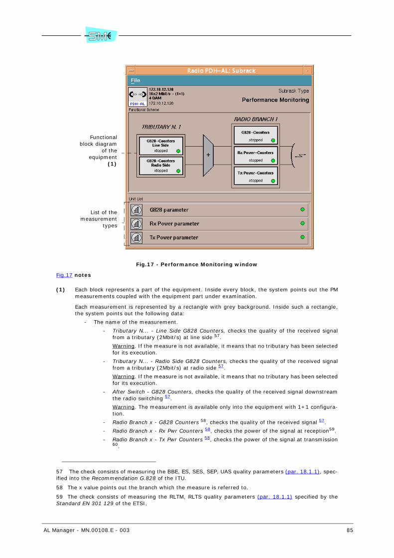
AL Manager - MN.00108.E - 003 85
Fig.17 - Performance Monitoring window
Fig.17 notes
(1) Each block represents a part of the equipment. Inside every block, the system points out the PMmeasurements coupled with the equipment part under examination.
Each measurement is represented by a rectangle with grey background. Inside such a rectangle,the system points out the following data:
- The name of the measurement.
- Tributary N... - Line Side G828 Counters, checks the quality of the received signalfrom a tributary (2Mbit/s) at line side 57.
Warning. If the measure is not available, it means that no tributary has been selectedfor its execution.
- Tributary N... - Radio Side G828 Counters, checks the quality of the received signalfrom a tributary (2Mbit/s) at radio side 57.
Warning. If the measure is not available, it means that no tributary has been selectedfor its execution.
- After Switch - G828 Counters, checks the quality of the received signal downstreamthe radio switching 57.
Warning. The measurement is available only into the equipment with 1+1 configura-tion.
- Radio Branch x - G828 Counters 58, checks the quality of the received signal 57.
- Radio Branch x - Rx Pwr Counters 58, checks the power of the signal at reception59.
- Radio Branch x - Tx Pwr Counters 58, checks the power of the signal at transmission60.
57 The check consists of measuring the BBE, ES, SES, SEP, UAS quality parameters (par. 18.1.1), spec-ified into the Recommendation G.828 of the ITU.
58 The x value points out the branch which the measure is referred to.
59 The check consists of measuring the RLTM, RLTS quality parameters (par. 18.1.1) specified by theStandard EN 301 129 of the ETSI.
List of themeasurement
types
Functionalblock diagram
of theequipment
(1)

86 AL Manager - MN.00108.E - 003
Warning. The availability of the measurements and their displaying into the Radio PDH-ASubrack – Performance Monitoring window are affected by the configuration of the equip-ment.
- The functioning status of the measurement:
- Stopped, the measurement is not on progress.
- Started, the measurement is on progress.
- The status of the alarms concerning the threshold exceeding relevant to the specific meas-urement. The status is pointed out by the colour of the small ball present into the block:
- Green, it has not been activated any alarm concerning the threshold exceeding.
- Red, orange, yellow or light blue, it has been activated at least one alarm concerningthe threshold exceeding and the most serious activated alarm has respectively theCritical, Major, Minor or Warning level.
18.1.1 Quality parameters description (PM)
- BBE (Background Block Errors). Number of blocks 61 where it has been detected at least oneerrored bit not belonging to SES.
- ES (Errored Second). The second when there have been one or more errored blocks.
- SES (Severely Errored Seconds). The second when there have been a percentage of erroredblocks > N% (the N value can be configured) or the second when it has been activated an alarmequivalent to the interruption of the signal at reception (Loss of Signal Alarm, Loss of FrameAlarm, B2 Excessive Ber Alarm, etc.).
- SEP (Severely Errored Period). Number of periods with a number of consecutive SES comprisedbetween 3 and 9. The sequence is ended by a second without SES.
- UAS (UnAvailable Seconds). Number of unavailability seconds. The counting of the secondsstarts after P consecutive seconds with SES presence and it ends at the beginning of a period ofQ consecutive seconds without SES. The P seconds are counted into the unavailability period.The Q and P values can be configured.
- RLTM (Received Level Tide Mark). Maximum value (TMMax) and minimum one (TMMin) reachedby the power at reception (RL) during the observation period (15 min or 24 hours).
- RLTS (Received Level Threshold Second). Number of seconds where it has been detected thatthe value of the power at reception (RL – Received Level) is lower than the pre–defined thresholdlevel. It is possible to define up to a maximum of 4 threshold levels.
- TLTM (Transmitted Level Tide Mark). Maximum value (TMMax) and the minimum one (TMMin)reached by the power at transmission (TL) during the observation period (15 min or 24 hours).
- TLTS (Transmitted Level Threshold Second). Number of seconds where it has been detectedthat the value of the power at transmission (TL – Transmitted Level) is higher than the pre–defined threshold level. It is possible to define up to a maximum of 4 threshold levels.
18.2 To activate/deactivate the PM measurements
1 Select the Performance Monitoring push-button.
It is displayed the Radio PDH-AL: Subrack – Performance Monitoring window (refer to Fig.17).
2 Double click with the left button of the mouse on the wished measure.
60 The check consists of measuring the TLTM, TLTS quality parameters (par. 18.1.1) specified by theStandard EN 301 129 of the ETSI.
61 The wording block refers to a group of bit.
AL Manager - MN.00108.E - 003 87
It is displayed the Radio PDH-AL: Unit - <measure name> window.
The Start Stop box points out the operating status of the measure. If the:
- Start value is active, the measurement is on progress.
- Stop value is active, the measurement is not on progress.
3 To check the currently set value in the equipment, select twice quickly on the parameter name andselect the Get push-button or the Commands – Send GET Request command.
4 To ACTIVATE the measurement:
a Select the box where it is pointed out the value.
b Choose the Start value.
c Select the Set push-button or the Commands – Send SET Request command.
To DEACTIVATE the measurement:
a Select the box where it is pointed out the value.
b Choose the Stop value.
c Select the Set push-button or the Commands – Send SET Request command.
18.3 To set the thresholds of the control parameters and the inter-vention ones of the alarms (PM)
1 Select the Performance Monitoring push-button.
It is displayed the Radio PDH-AL: Subrack – Performance Monitoring window (refer to Fig.17).
2 In the Unit List area, select the type of measure for which you wish to verify the thresholds.
It is displayed the Radio PDH-AL: Unit - … Parameters window.
Depending on the type of selected measure, the following parameters will be pointed out in the win-dow:
- G828 parameter
- Num. SES to set UAS. Threshold level – expressed by means of the number of con-secutive seconds with SES – over which it starts the UAS unavailability period (P val-ue).
- Num. SES to reset UAS. Threshold level – expressed by means of the number of con-secutive seconds without SES – over which it ends the UAS unavailability period (Qvalue).
- Percent. BBE to set SES. Threshold level – expressed by means of the percentage ofthe errored block number – over which it is declared a SES.
- 15 Min ES Threshold. Threshold level – expressed by means of the number of secondsinside a period of 15 minutes where it has occurred ES – over which it is activated therelevant alarm 62.
- 15 Min SES Threshold. Threshold level – expressed by means of the number of sec-onds inside a period of 15 minutes where it has occurred SES – over which it is acti-vated the relevant alarm 62.
- 15 Min SEP Threshold. Threshold level – expressed by means of the number of sec-onds inside a period of 15 minutes where it has occurred SEP – over which it is acti-vated the relevant alarm 62.
- 24 Hour ES Threshold. Threshold level – expressed by means of the number of sec-onds inside a period of 24 hours where it has occurred ES – over which it is activatedthe relevant alarm 62.
62 The value 0 represents the deactivation of the threshold.

88 AL Manager - MN.00108.E - 003
- 24 Hour SES Threshold. Threshold level – expressed by means of the number of sec-onds inside a period of 24 hours where it has occurred SES – over which it is activatedthe relevant alarm 62.
- 24 Hour SEP Threshold. Threshold level – expressed by means of the number of sec-onds inside a period of 24 hours where it has occurred SEP – over which it is activatedthe relevant alarm 62.
- Rx Power parameter
- 24 Hour Rlts1 (Rlts2, Rlts3, Rlts4) Threshold. Threshold levels – expressed by meansof the number of seconds inside a period of 24 hours where the received power isrespectively lower than the RLT1, RLT2, RLT3, RLT4 threshold level – over which thesystem activates the relevant alarms 62.
- 15 Min Rlts1 (Rlts2, Rlts3, Rlts4) Threshold. Threshold levels – expressed by meansof the number of seconds inside a period of 15 minutes where the received power isrespectively lower than the RLT1, RLT2, RLT3, RLT4 threshold level – over which thesystem activates the relevant alarms 62.
- Tx Power parameter
- 24 Hour Tlts1 (Tlts2, Tlts3, Tlts4) Threshold. Threshold levels – expressed by meansof the number of seconds inside a period of 24 hours where the transmitted power isrespectively higher than the TLT1, TLT2, TLT3, TLT4 threshold level – over which thesystem activates the relevant alarms 62.
- 15 Min Tlts1 (Tlts2, Tlts3, Tlts4) Threshold. Threshold levels – expressed by meansof the number of seconds inside a period of 15 minutes where the transmitted poweris respectively higher than the TLT1, TLT2, TLT3, TLT4 threshold level – over whichthe system activates the relevant alarms 62.
3 To check the currently set value in the equipment, select twice quickly on the parameter name andselect the Get push-button or the Commands – Send GET Request command.
4 To change a parameter:
a Move the cursor on the desired value.
b Select the Set push-button or the Commands – Send SET Request command.
18.4 To set the thresholds of the Rx and Tx power level (PM)
1 Select the Performance Monitoring push-button.
It is displayed the Radio PDH-AL: Subrack – Performance Monitoring window (refer to Fig.17).
2 Double click with the left button of the mouse on the wished power measure (...Rx Pwr or ...Tx Pwr).
It is displayed the Radio PDH-AL: Unit - <measure name> window.
Depending on the type of selected measure, the following parameters will be pointed out in the win-dow:
- (... Rx Pwr) Received Power Level Threshold 1 (2, 3, 4). It is respectively the first, the sec-ond, the third and the fourth threshold level of the received power.
- (...Tx Pwr) Tx Power Lever Threshold 1 (2, 3, 4). It is respectively the first, the second, thethird and the fourth threshold level of the transmitted power.
3 To check the currently set value in the equipment, select twice quickly on the parameter name andselect the Get push-button or the Commands – Send GET Request command.
4 To change a parameter:
a Move the cursor on the desired value.
b Select the Set push-button or the Commands – Send SET Request command.

AL Manager - MN.00108.E - 003 89
18.5 To reset of the alarms concerning the threshold exceeding (PM)
1 Select the Performance Monitoring push-button.
It is displayed the Radio PDH-AL: Subrack – Performance Monitoring window (refer to Fig.17).
2 Double click with the left button of the mouse on the wished measure.
It is displayed the Radio PDH-AL: Unit - <measure name> window.
3 Select the Send Request push-button (Alarm Clear parameter) and confirm.
18.6 To reset the values concerning the control parameters (PM)
1 Select the Performance Monitoring push-button.
It is displayed the Radio PDH-AL: Subrack – Performance Monitoring window (refer to Fig.17).
2 Double click with the left button of the mouse on the wished measure.
It is displayed the Radio PDH-AL: Unit - <measure name> window.
3 Select the Send Request push-button (Counter Clear parameter) and confirm.

90 AL Manager - MN.00108.E - 003
19 EQ. EAST - EQ. WEST (PUSH-BUTTONS)
Warning. The Eq. East and Eq. West push-buttons are available only for AL equipment Terminal16x2 East-West type.
The Eq. East push-button allows to display/modify the general configuration parameters of the east branchof the local equipment.
The Eq. West push-button allows to display/modify the general configuration parameters of the westbranch of the local equipment.
With details, it is possible to display/modify:
- Capacity of the of the specific branch - local equipment (par. 19.1) (Local Capacity...)
- Capacity of the specific branch - local and remote equipment (par. 19.2) (Link Capacity)
- Modulation of the specific branch - local equipment (par. 19.3) (Local Modulation Type)
- Modulation of the specific branch - local and remote equipment (par. 19.4) (Link ModulationType)
- Connection identificative number of the specific branch - local equipment (par. 19.5) (Local LinkID...)
- Connection identificative number of the specific branch - local and remote equipment (par. 19.6)(Link ID)
- Threshold of the signal at reception, under which the related alarms are activated (par. 19.7)(Rx Signal Level Alarm Thresh)
- LBER alarm threshold (par. 19.8) (LBer Threshold)
- HBER alarm threshold (par. 19.9) (HBer Threshold)
- EWL alarm threshold (par. 19.10) (Early Warning Threshold)
19.1 To verify/modify the capacity of the specific branch - local equipment
1 Select the Eq. East or Eq. West push-button.
The Radio PDH-AL: Unit – Radio Equipment... window opens with the Settings card active.
The Local Capacity (Local NE) parameter, points out the capacity of the specific branch.
2 To check the currently set value in the equipment, select twice quickly on the parameter name andselect the Get push-button or the Commands – Send GET Request command.
3 To change the parameter:
a Select the box where it is pointed out the value.
b Choose the new value from the list.
c Select the Set push-button or the Commands – Send SET Request command.
Warning. After this modification, the system will automatically execute a new channelling of theequipment on the channel nearest to the RF channel corresponding to the new capacity.
If the message “This feature is not enabled” is displayed, it means that the selected capacity is notenabled for the that equipment 52.

AL Manager - MN.00108.E - 003 91
19.2 To verify/modify the capacity of the specific branch - local and remote equipment
1 Select the Eq. East or Eq. West push-button.
The Radio PDH-AL: Unit – Radio Equipment... window opens with the Settings card active.
The Link Capacity parameter, points out the capacity of the specific branch.
2 To check the currently set value in the equipment, select twice quickly on the parameter name andselect the Get push-button or the Commands – Send GET Request command.
3 To change the parameter:
a Select the box where it is pointed out the value.
b Choose the new value from the list.
c Select the Set push-button or the Commands – Send SET Request command.
Warning. After this change, the system automatically will execute a re–channelling of the equipmenton the channel nearest to the RF channel corresponding to the new capacity.
If, after the change of the capacity, operating problems occurred, the program automatically re-stores the previous value.
If the message “This feature is not enabled”, it means that the selected capacity is not enabled forthe local and/or remote equipment 52.
19.3 To verify/modify the modulation of the specific branch - local equipment
1 Select the Eq. East or Eq. West push-button.
The Radio PDH-AL: Unit – Radio Equipment... window opens with the Settings card active.
The Local Modulation Type parameter, points out the modulation of the specific branch.
2 To check the currently set value in the equipment, select twice quickly on the parameter name andselect the Get push-button or the Commands – Send GET Request command.
3 To change the parameter:
a Select the box where it is pointed out the value.
b Choose the new value from the list.
c Select the Set push-button or the Commands – Send SET Request command.
Warning. If the message “This feature is not enabled” is displayed, it means that the selected mod-ulation is not enabled for the that equipment 52.
19.4 To verify/modify the modulation of the specific branch - local and remote equipment
1 Select the Eq. East or Eq. West push-button.
The Radio PDH-AL: Unit – Radio Equipment... window opens with the Settings card active.
The Link Modulation Type parameter, points out the modulation of the specific branch.
92 AL Manager - MN.00108.E - 003
2 To check the currently set value in the equipment, select twice quickly on the parameter name andselect the Get push-button or the Commands – Send GET Request command.
3 To change the parameter:
a Select the box where it is pointed out the value.
b Choose the new value from the list.
c Select the Set push-button or the Commands – Send SET Request command.
Warning. After this change, the system automatically will execute a re–channelling of the equipmenton the channel nearest to the RF channel corresponding to the new modulation.
If, after the change of the modulation, operating problems occurred, the program automatically re-stores the previous value.
If the message “This feature is not enabled”, it means that the selected modulation is not enabledfor the local and/or remote equipment 52.
19.5 To verify/modify the connection identificative number of the specific branch - local equipment
1 Select the Eq. East or Eq. West push-button.
The Radio PDH-AL: Unit – Radio Equipment... window opens with the Settings card active.
The Local Link ID (Local NE) parameter, points out the identificative number of the specific branch.
2 To check the currently set value in the equipment, select twice quickly on the parameter name andselect the Get push-button or the Commands – Send GET Request command.
3 To change the parameter:
a Move the cursor to the wished value.
Warning. The presetting of the 0 value, corresponds to the lack of the identification selection.
b Select the Set push-button or the Commands – Send SET Request command.
19.6 To verify/modify the connection identificative number of the specific branch - local and remote equipment
1 Select the Eq. East or Eq. West push-button.
The Radio PDH-AL: Unit – Radio Equipment... window opens with the Settings card active.
The Link ID, points out the identificative number of the specific branch.
2 To check the currently set value in the equipment, select twice quickly on the parameter name andselect the Get push-button or the Commands – Send GET Request command.
3 To change the parameter:
a Move the cursor to the wished value.
Warning. The presetting of the 0 value, corresponds to the lack of the identification selection.
b Select the Set push-button or the Commands – Send SET Request command.
Warning. If, after the change of the identificative number, operating problems occurred, the pro-gram automatically restores the previous value.
AL Manager - MN.00108.E - 003 93
19.7 To verify/modify the threshold of the signal at reception, un-der which the related alarms are activated
1 Select the Eq. East or Eq. West push-button.
The Radio PDH-AL: Unit – Radio Equipment... window opens with the Settings card active.
The Rx Signal Level Alarm Thresh, points out the threshold of the signal at reception, under whichthe related alarms are activated.
2 To check the currently set value in the equipment, select twice quickly on the parameter name andselect the Get push-button or the Commands – Send GET Request command.
3 To change the parameter:
a Move the cursor to the wished value.
b Select the Set push-button or the Commands – Send SET Request command.
19.8 To verify/modify the LBER alarm threshold
1 Select the Eq. East or Eq. West push-button.
The Radio PDH-AL: Unit – Radio Equipment... window opens with the Settings card active.
The LBer Threshold parameter, points out the intervention threshold of the LBER alarm:
- e-6, the alarm is activated when a BER > 10-6 is detected.
- e-7, the alarm is activated when a BER > 10-7 is detected.
- e-8, the alarm is activated when a BER > 10-8 is detected.
2 To check the currently set value in the equipment, select twice quickly on the parameter name andselect the Get push-button or the Commands – Send GET Request command.
3 To change the parameter:
a Select the box where it is pointed out the value.
b Choose the new value from the list.
c Select the Set push-button or the Commands – Send SET Request command.
19.9 To verify/modify the HBER alarm threshold
1 Select the Eq. East or Eq. West push-button.
The Radio PDH-AL: Unit – Radio Equipment... window opens with the Settings card active.
The HBer Threshold parameter, points out the intervention threshold of the HBER alarm:
- e-3, the alarm is activated when a BER > 10-3 is detected.
- e-4, the alarm is activated when a BER > 10-4 is detected.
- e-5, the alarm is activated when a BER > 10-5 is detected.
2 To check the currently set value in the equipment, select twice quickly on the parameter name andselect the Get push-button or the Commands – Send GET Request command.
3 To change the parameter:
a Select the box where it is pointed out the value.
b Choose the new value from the list.

94 AL Manager - MN.00108.E - 003
c Select the Set push-button or the Commands – Send SET Request command.
19.10 To verify/modify the EWL alarm threshold
1 Select the Eq. East or Eq. West push-button.
The Radio PDH-AL: Unit – Radio Equipment... window opens with the Settings card active.
The Early Warning Threshold parameter, points out the intervention threshold of the EWL alarm:
- e-9, the alarm is activated when a BER > 10-9 is detected.
- e-10, the alarm is activated when a BER > 10-10 is detected.
- e-11, the alarm is activated when a BER > 10-11 is detected.
- e-12, the alarm is activated when a BER > 10-12 is detected.
2 To check the currently set value in the equipment, select twice quickly on the parameter name andselect the Get push-button or the Commands – Send GET Request command.
3 To change the parameter:
a Select the box where it is pointed out the value.
b Choose the new value from the list.
c Select the Set push-button or the Commands – Send SET Request command.
AL Manager - MN.00108.E - 003 95
20 BASE BAND (CONTEXTUAL AREA)
The Base Band contextual area allows to verify/modify the configuration parameter of the base band sec-tion.
Depending on the equipment type the configuration parameters change:
- AL equipment version 1 unit with 2Mb/s interface, refer to the paragraph 20.1.
- AL equipment version 1 unit with Ethernet Lan interface, refer to the paragraph 20.2.
- AL equipment compact version, refer to the paragraph 20.3.
- AL equipment version 2 units with 32x2Mbit/s capacity, refer to the paragraph 20.4.
- AL equipment version 2 units Terminal 16x2 East-West, refer to the paragraph 20.5.
20.1 AL equipment version 1 unit with 2Mb/s interface
The Base Band contextual area, for the AL equipment version 1 unit with 2Mb/s interface, allows to:
- To verify the tributary status (AL 1U 2Mbit/s) (par. 20.1.1)
- To verify the alarms of LIM… block (AL 1U 2Mbit/s) (par. 20.1.2)
- To verify/modify the configuration parameters of LIM unit (AL 1U 2Mbit/s) (par. 20.1.3)
- To activate/deactivate the tributaries use (AL 1U 2Mbit/s) (par. 20.1.4)
- To activate/deactivate the tributary line side loops (AL 1U 2Mbit/s) (par. 20.1.5)
- To activate/deactivate the tributary internal side loops (AL 1U 2Mbit/s) (par. 20.1.6)
20.1.1 To verify the tributary status (AL 1U 2Mbit/s)
1 In the equipment view area, double click with the left button of the mouse on Base Band contextualarea.
The Radio PDH-AL: Subrack - Base Band... window is displayed, where the status of the tributaries,of the loops and of the alarms is displayed as depicted in Fig.18.
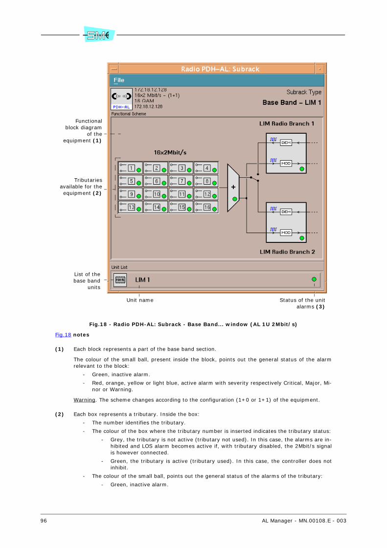
96 AL Manager - MN.00108.E - 003
Fig.18 - Radio PDH-AL: Subrack - Base Band... window (AL 1U 2Mbit/s)
Fig.18 notes
(1) Each block represents a part of the base band section.
The colour of the small ball, present inside the block, points out the general status of the alarmrelevant to the block:
- Green, inactive alarm.
- Red, orange, yellow or light blue, active alarm with severity respectively Critical, Major, Mi-nor or Warning.
Warning. The scheme changes according to the configuration (1+0 or 1+1) of the equipment.
(2) Each box represents a tributary. Inside the box:
- The number identifies the tributary.
- The colour of the box where the tributary number is inserted indicates the tributary status:
- Grey, the tributary is not active (tributary not used). In this case, the alarms are in-hibited and LOS alarm becomes active if, with tributary disabled, the 2Mbit/s signalis however connected.
- Green, the tributary is active (tributary used). In this case, the controller does notinhibit.
- The colour of the small ball, points out the general status of the alarms of the tributary:
- Green, inactive alarm.
Functionalblock diagram
of theequipment (1)
List of thebase band
units
Unit name Status of the unitalarms (3)
Tributariesavailable for theequipment (2)
AL Manager - MN.00108.E - 003 97
- Red, orange, yellow or light blue, active alarm with severity respectively Critical, Ma-jor, Minor or Warning.
- The terminals, point out the status of the tributary loops:
- , the tributary loops are deactivated
- , the tributary loop–line side is activated
- , the tributary loop–inner side is activated
- , the tributary loop–line side and inner–side are activated
Warning. The number of tributaries changes depending on the equipment capacity.
(3) The colour of the small ball points out the general status of the alarm:
- Green, inactive alarm.
- Red, orange, yellow or light blue, active alarm with severity respectively Critical, Major, Mi-nor or Warning.
20.1.2 To verify the alarms of LIM… block (AL 1U 2Mbit/s)
1 In the equipment view area, double click with the left button of the mouse on Base Band contextualarea.
The system displays the Radio PDH-AL: Subrack – Base Band… window (refer to Fig.18).
2 Select the LIM... block.
It is displayed the Radio PDH-AL: Unit – LIM… window.
The Alarm Status area points out the status of the alarm. The box of colour:
- Green, inactive alarm.
- Red, orange, yellow or light blue, active alarm with severity respectively Critical, Major, Mi-nor or Warning.
20.1.3 To verify/modify the configuration parameters of the LIM unit (AL 1U 2Mbit/s)
1 In the equipment view area, double click with the left button of the mouse on Base Band contextualarea.
The system displays the Radio PDH-AL: Subrack – Base Band… window (refer to Fig.18).
2 Into the Unit List area, select the LIM... unit.
It is displayed the Radio PDH-AL: Unit – <unit name> window.
The box:
- Expected Type. Expected unit type.
A difference between the really present unit (Label parameter) and the expected one acti-vates an alarm (Unit Hw Mismatch Alarm).
The Unequipped wording points out that the unit is not equipped.
- Label. Unit type really present into the equipment.
The Unequipped wording points out that the unit is not physically present into the equip-ment.
- Hardware Edition. Unit version.
- Part Number. Unit Part Number.
98 AL Manager - MN.00108.E - 003
- Parent Part Number. Part number of the group that contains the unit.
Usually, the group represents the part of the equipment that can be replaced.
Warning. Not all the units are included into a group. In this case, the field will result emptyand the part of the equipment that can be replaced will correspond to the unit itself.
- Serial Number. The serial number of the group that contains the unit.
Warning. If the unit is not contained into a group (the Parent Part Number field is empty),the Serial Number refers to the unit.
The Alarm Status area points out the status of the unit alarm. The box of colour:
- Green, inactive alarm.
- Red, orange, yellow or light blue, active alarm with severity respectively Critical, Major, Mi-nor or Warning.
3 To check the currently set value in the equipment, select twice quickly on the parameter name andselect the Get push-button or the Commands – Send GET Request command.
4 To change the Hardware Edition and/or Part Number parameter:
a Type into the relevant box an alphanumeric string with a minimum of 1 and a maximum of20 characters (Hardware Edition) and minimum of 1 and a maximum of 30 characters (PartNumber).
b Select the Set push-button or the Commands – Send SET Request command.
20.1.4 To activate/deactivate the tributaries use (AL 1U 2Mbit/s)
1 In the equipment view area, double click with the left button of the mouse on Base Band contextualarea.
The system displays the Radio PDH-AL: Subrack – Base Band… window (refer to Fig.18).
2 Double click with the left button of the mouse on the tributary to be enabled (or disabled).
The system displays the Radio PDH-AL: Unit PDH_AL Physical interface... window
The Enable parameter, points out the tributary use:
- Enable, tributary used.
- Disable, tributary not used.
3 To check the currently set value in the equipment, select twice quickly on the parameter name andselect the Get push-button or the Commands – Send GET Request command.
4 To change the parameter:
a Select the box where it is pointed out the value.
b Choose the new value from the list.
c Select the Set push-button or the Commands – Send SET Request command.
20.1.5 To activate/deactivate the tributary line side loops (AL 1U 2Mbit/s)
1 In the equipment view area, double click with the left button of the mouse on Base Band contextualarea.
The system displays the Radio PDH-AL: Subrack – Base Band… window (refer to Fig.18).
2 Double click with the left button of the mouse on the tributary to be enabled (or disabled).
The system displays the Radio PDH-AL: Unit PDH_AL Physical interface... window
The Line Loop parameter, points out the status of tributary line side loop:
- Loop Off, the loop is deactivated (default setting).
AL Manager - MN.00108.E - 003 99
- Loop On, the loop is activated (activation of the manual operation).
3 To check the currently set value in the equipment, select twice quickly on the parameter name andselect the Get push-button or the Commands – Send GET Request command.
4 To change the parameter:
a Select the box where it is pointed out the value.
b Choose the new value from the list.
c Select the Set push-button or the Commands – Send SET Request command.
It is displayed the confirm window.
Warning. Only if you are activating loop (selection of the Loop On value) a message is dis-played warning that you are executing a forcing and displaying the current setting of timeout41.
d Select the Ok push-button.
The activating of the loop activates the MAN. OP alarm. If the equipment is switched offand, then, switched on, the transmitter is on, independently from the previous setting.
20.1.6 To activate/deactivate the tributary internal side loops (AL 1U 2Mbit/s)
1 In the equipment view area, double click with the left button of the mouse on Base Band contextualarea.
The system displays the Radio PDH-AL: Subrack – Base Band… window (refer to Fig.18).
2 Double click with the left button of the mouse on the tributary to be enabled (or disabled).
The system displays the Radio PDH-AL: Unit PDH_AL Physical interface... window
The Internal Loop parameter, points out the status of tributary internal side loop:
- Loop Off, the loop is deactivated (default setting).
- Loop On, the loop is activated (activation of the manual operation).
3 To check the currently set value in the equipment, select twice quickly on the parameter name andselect the Get push-button or the Commands – Send GET Request command.
4 To change the parameter:
a Select the box where it is pointed out the value.
b Choose the new value from the list.
c Select the Set push-button or the Commands – Send SET Request command.
It is displayed the confirm window.
Warning. Only if you are activating loop (selection of the Loop On value) a message is dis-played warning that you are executing a forcing and displaying the current setting of timeout41.
d Select the Ok push-button.
The activating of the loop activates the MAN. OP alarm. If the equipment is switched offand, then, switched on, the transmitter is on, independently from the previous setting.
20.2 AL equipment version 1 unit with Ethernet Lan interface
The Base Band contextual area, for the AL equipment version 1 unit with Ethernet Lan interface, allows to:
- To verify the block diagram of the equipment (AL 1U Ethernet) (par. 20.2.1)
- To verify the alarms of LIM… block (AL 1U Ethernet) (par. 20.2.2)
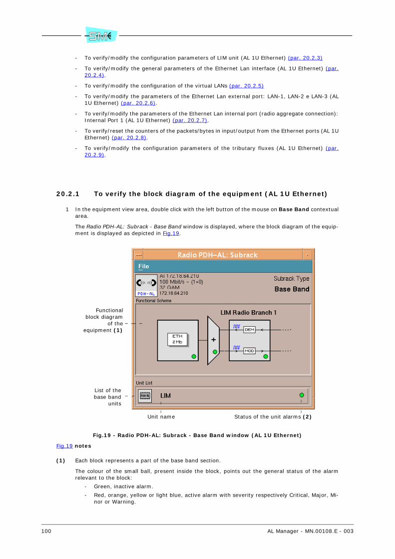
100 AL Manager - MN.00108.E - 003
- To verify/modify the configuration parameters of LIM unit (AL 1U Ethernet) (par. 20.2.3)
- To verify/modify the general parameters of the Ethernet Lan interface (AL 1U Ethernet) (par.20.2.4).
- To verify/modify the configuration of the virtual LANs (par. 20.2.5)
- To verify/modify the parameters of the Ethernet Lan external port: LAN-1, LAN-2 e LAN-3 (AL1U Ethernet) (par. 20.2.6).
- To verify/modify the parameters of the Ethernet Lan internal port (radio aggregate connection):Internal Port 1 (AL 1U Ethernet) (par. 20.2.7).
- To verify/reset the counters of the packets/bytes in input/output from the Ethernet ports (AL 1UEthernet) (par. 20.2.8).
- To verify/modify the configuration parameters of the tributary fluxes (AL 1U Ethernet) (par.20.2.9).
20.2.1 To verify the block diagram of the equipment (AL 1U Ethernet)
1 In the equipment view area, double click with the left button of the mouse on Base Band contextualarea.
The Radio PDH-AL: Subrack - Base Band window is displayed, where the block diagram of the equip-ment is displayed as depicted in Fig.19.
Fig.19 - Radio PDH-AL: Subrack - Base Band window (AL 1U Ethernet)
Fig.19 notes
(1) Each block represents a part of the base band section.
The colour of the small ball, present inside the block, points out the general status of the alarmrelevant to the block:
- Green, inactive alarm.
- Red, orange, yellow or light blue, active alarm with severity respectively Critical, Major, Mi-nor or Warning.
List of thebase band
units
Unit name Status of the unit alarms (2)
Functionalblock diagram
of theequipment (1)

AL Manager - MN.00108.E - 003 101
Warning. The scheme changes according to the configuration (1+0 or 1+1) of the equipment.
(2) The colour of the small ball points out the general status of the alarm:
- Green, inactive alarm.
- Red, orange, yellow or light blue, active alarm with severity respectively Critical, Major, Mi-nor or Warning.
20.2.2 To verify the alarms of LIM… block (AL 1U Ethernet)
1 In the equipment view area, double click with the left button of the mouse on Base Band contextualarea.
The system displays the Radio PDH-AL: Subrack – Base Band window (refer to Fig.19).
2 Select the LIM... block.
It is displayed the Radio PDH-AL: Unit – LIM… window.
The Alarm Status area points out the status of the alarm. The box of colour:
- Green, inactive alarm.
- Red, orange, yellow or light blue, active alarm with severity respectively Critical, Major, Mi-nor or Warning.
20.2.3 To verify/modify the configuration parameters of the LIM unit (AL 1U Ethernet)
1 In the equipment view area, double click with the left button of the mouse on Base Band contextualarea.
The system displays the Radio PDH-AL: Subrack – Base Band window (refer to Fig.19).
2 Into the Unit List area, select the LIM... unit.
It is displayed the Radio PDH-AL: Unit – <unit name> window.
The box:
- Expected Type. Expected unit type.
A difference between the really present unit (Label parameter) and the expected one acti-vates an alarm (Unit Hw Mismatch Alarm).
The Unequipped wording points out that the unit is not equipped.
- Label. Unit type really present into the equipment.
The Unequipped wording points out that the unit is not physically present into the equip-ment.
- Hardware Edition. Unit version.
- Part Number. Unit Part Number.
- Parent Part Number. Part number of the group that contains the unit.
Usually, the group represents the part of the equipment that can be replaced.
Warning. Not all the units are included into a group. In this case, the field will result emptyand the part of the equipment that can be replaced will correspond to the unit itself.
- Serial Number. The serial number of the group that contains the unit.
Warning. If the unit is not contained into a group (the Parent Part Number field is empty),the Serial Number refers to the unit.
The Alarm Status area points out the status of the unit alarm. The box of colour:
- Green, inactive alarm.
- Red, orange, yellow or light blue, active alarm with severity respectively Critical, Major, Mi-nor or Warning.
102 AL Manager - MN.00108.E - 003
3 To check the currently set value in the equipment, select twice quickly on the parameter name andselect the Get push-button or the Commands – Send GET Request command.
4 To change the Hardware Edition and/or Part Number parameter:
a Type into the relevant box an alphanumeric string with a minimum of 1 and a maximum of20 characters (Hardware Edition) and minimum of 1 and a maximum of 30 characters (PartNumber).
b Select the Set push-button or the Commands – Send SET Request command.
20.2.4 To verify/modify the general parameters of the Ethernet Lan in-terface (AL 1U Ethernet)
As regards the general parameter of the Ethernet interface, the Base Band contextual area, allows:
- To verify/modify the maximum number of MAC Addresses managed per port (par. 20.2.4.1)
- To check and modify the aging time of the MAC addresses stored in the specific table (par.20.2.4.2)
- To verify/modify the “emptying algorithm” of the messages present in the output queue (par.20.2.4.3)
- To verify/modify which output queue a packet, in input to any Ethernet port, must be assigned,depending on its Tag 802.1p (par. 20.2.4.4)
- To verify/modify the maximum size of the accepted packet (par. 20.2.4.5)
- To verify/modify the time interval (hysteresis) after which the Link Loss Forwarding modality isactivated (par. 20.2.4.6)
20.2.4.1 To verify/modify the maximum number of MAC Addresses managed per port (AL 1U Ethernet)
1 In the equipment view area, double click with the left button of the mouse on Base Band contextualarea.
The system displays the Radio PDH-AL: Subrack – Base Band window (refer Fig.19).
2 Select the ETH 2Mb block.
The system displays the Radio PDH-AL: Subrack – Ethernet-2Mb window.
3 Select the Ethernet Switch block.
The system displays the Radio PDH-AL: Unit - ETH SWITCH window.
The Max Num. Of MAC Addr. parameter, the maximum number of MAC Addresses managed per portis displayed: : 512, 1024, 2048 63.
4 To check the currently set value in the equipment, select twice quickly on the parameter name andselect the Get push-button or the Commands – Send GET Request command.
5 To change the parameter:
a Select the box where it is pointed out the value.
b Choose the new value from the list.
c Select the Set push-button or the Commands – Send SET Request command.
63 The switch has a memory area common to all the active ports, where the “SOURCE MAC” of the packetsincoming in each port are stored.
The table allows then to determinate the port to send the messages as function of the “destination MACs”.The information present in the table are dynamic and their maximum number and validity time can be setby the user.

AL Manager - MN.00108.E - 003 103
20.2.4.2 To check and modify the aging time of the MAC addresses stored in the specific table (AL 1U Ethernet)
1 In the equipment view area, double click with the left button of the mouse on Base Band contextualarea.
The system displays the Radio PDH-AL: Subrack – Base Band window (refer Fig.19).
2 Select the ETH 2Mb block.
The system displays the Radio PDH-AL: Subrack – Ethernet-2Mb window.
3 Select the Ethernet Switch block.
The system displays the Radio PDH-AL: Unit - ETH SWITCH window.
The MAC Addr. Aging Time parameter, points out the aging time of the MAC addresses stored in thespecific table 63.
4 To check the currently set value in the equipment, select twice quickly on the parameter name andselect the Get push-button or the Commands – Send GET Request command.
5 To change the parameter:
a Move the cursor on the wished value.
b Select the Set push-button or the Commands – Send SET Request command.
20.2.4.3 To verify/modify the “emptying algorithm” of the messages present in the output queue (AL 1U Ethernet)
1 In the equipment view area, double click with the left button of the mouse on Base Band contextualarea.
The system displays the Radio PDH-AL: Subrack – Base Band window (refer Fig.19).
2 Select the ETH 2Mb block.
The system displays the Radio PDH-AL: Subrack – Ethernet-2Mb window.
3 Select the Ethernet Switch block.
The system displays the Radio PDH-AL: Unit - ETH SWITCH window.
The Egress Priority Policy parameter points out the emptying algorithm of the output queues:
- StrictPriority, the queue with highest priority is completely emptied (sending of all the mes-sages) before sending a message of the queue with lower priority.
- wfq8421, a part (8 messages) of the queue with highest priority is empties, then a part ofthe queue with lower priority (4 messages), then a part of the queue with further lower pri-ority (2 messages), then a part of the queue with lowest priority (1 message) and so on re-starting from the queue with highest priority.
4 To check the currently set value in the equipment, select twice quickly on the parameter name andselect the Get push-button or the Commands – Send GET Request command.
5 To change the parameter:
a Select the box where it is pointed out the value.
b Choose the new value from the list.
c Select the Set push-button or the Commands – Send SET Request command.
20.2.4.4 To verify/modify which output queue a packet, in input to any Ethernet port, must be assigned, depending on its Tag 802.1p (AL 1U Ethernet)
1 In the equipment view area, double click with the left button of the mouse on Base Band contextualarea.
The system displays the Radio PDH-AL: Subrack – Base Band window (refer Fig.19).

104 AL Manager - MN.00108.E - 003
2 Select the ETH 2Mb block.
The system displays the Radio PDH-AL: Subrack – Ethernet-2Mb window.
3 Select the Ethernet Switch block.
The system displays the Radio PDH-AL: Unit - ETH SWITCH window.
In the Global 802.1p Priority Management area, the current setting “output queues– Tag 802.1p”is displayed as in Fig.20
4 To check the currently set value in the equipment, select twice quickly on the parameter name andselect the Get push-button or the Commands – Send GET Request command.
5 To change the parameter:
a Activate the option push-button corresponding to the wished combination “output queue -Tag 802.1p”.
It is possible to activate the option push-button of only an output queue at a time.
b Select the Set push-button or the Commands – Send SET Request command.
Fig.20 - Global 802.1p Priority Management table (AL 1U Ethernet)
Notes of Fig.20
(1) A packet in input from any Ethernet port of the equipment, having a valid value of priority Tag802.1p, is automatically assigned to one of the four queues of the output port, according to whatreported in the Global 802.1p Priority management table.
For example, with reference to the figures, the packets in input with Tag 802.1p equal to 0, 1, 2,or 3 will be assigned to the queue with lower priority (Queue 0), while the packets with Tag 802.1pequal to 4, 5, 6 or 7, to the output queue with highest priority (Queue 3).
Warning. What just said is valid only if the analysis of the priority at level 3 – field TOS/DSCP is notactive and prioritary 64.
(2) Each Ethernet port of the equipment has four output queue, which the packets in input from otherports are sent to. The wording:
- Queue 0, indicates the queue with 0 priority (lowest priority)
- Queue 1, indicates the queue with 1 priority
- Queue 2, indicates the queue with 2 priority
- Queue 3, indicates the queue with 3 priority (highest priority)
(3) The active push-button indicates which output queue (Queue…) the packet in input is associated to,whose value of priority Tag (802.1p) corresponds to the value 0, 1, 2, 3, 4, 5, 6 or 7.
Warning. The Global 802.1p Priority Management table is COMMON to all the Ethernet port of theequipment.
64 The AL radio equipment allows analysing the priority at level 2, according the standard 802.1p (values0… 7), or at level 3, through the analysis of the PTOS/DSCP field present in the header of the IP packets(values 0… 63). The choice of which priority standard must be used can be modified by the user and canbe different for each port of the equipment: internal (Internal Port) and external (Lan 1, Lan 2, Lan 3).
This area indicates whi-ch output queue a pac-ket must be assigned to, depending on its 802.1p priority Tag (1)
Output queue (2)available in theequipment (3)
Tag 802.1p valueof the packet in
input to a port ofthe equipment (3)

AL Manager - MN.00108.E - 003 105
20.2.4.5 To verify/modify the maximum size of the accepted packet (AL 1U Ether-net)
1 In the equipment view area, double click with the left button of the mouse on Base Band contextualarea.
The system displays the Radio PDH-AL: Subrack – Base Band window (refer Fig.19).
2 Select the ETH 2Mb block.
The system displays the Radio PDH-AL: Subrack – Ethernet-2Mb window.
3 Select the Ethernet Switch block.
The system displays the Radio PDH-AL: Unit - ETH SWITCH window.
The Max Packet Size parameter, the maximum size of the accepted packet is pointed out:
- s-1522, maximum size for standard Ethernet.
- s-1536, maximum size for non-standard Ethernet up to 1536.
4 To check the currently set value in the equipment, select twice quickly on the parameter name andselect the Get push-button or the Commands – Send GET Request command.
5 To change the parameter:
a Select the box where it is pointed out the value.
b Choose the new value from the list.
c Select the Set push-button or the Commands – Send SET Request command.
20.2.4.6 To verify/modify the time interval (hysteresis) after which the Link Loss Forwarding modality is activated (AL 1U Ethernet)
1 In the equipment view area, double click with the left button of the mouse on Base Band contextualarea.
The system displays the Radio PDH-AL: Subrack – Base Band window (refer Fig.19).
2 Select the ETH 2Mb block.
The system displays the Radio PDH-AL: Subrack – Ethernet-2Mb window.
3 Select the Ethernet Switch block.
The system displays the Radio PDH-AL: Unit - ETH SWITCH window.
The LLF Wait Time parameter displays the setting of the hysteresis of the Link Loss Forwarding mo-dality.
4 To check the currently set value in the equipment, select twice quickly on the parameter name andselect the Get push-button or the Commands – Send GET Request command.
5 To change the parameter:
a Move the cursor to the wished value.
b Select the Set push-button or the Commands – Send SET Request command.
20.2.5 To verify/modify the configuration of the virtual LANs (AL 1U Eth-ernet)
As regards the configuration of the virtual LANs, the Base Band contextual area, allows:
- To verify the existing virtual Lans (par. 20.2.5.1)
- To create a virtual Lan (par. 20.2.5.2)
- To delete a virtual Lan (par. 20.2.5.3)
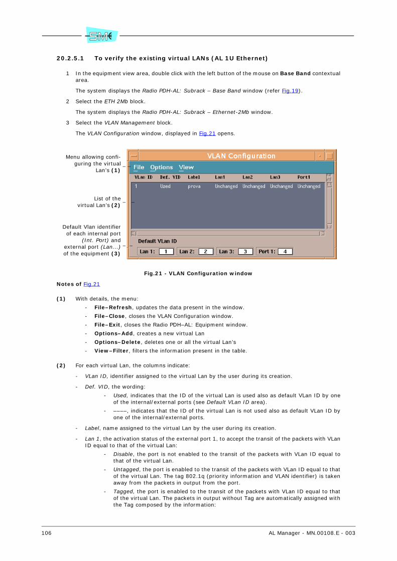
106 AL Manager - MN.00108.E - 003
20.2.5.1 To verify the existing virtual LANs (AL 1U Ethernet)
1 In the equipment view area, double click with the left button of the mouse on Base Band contextualarea.
The system displays the Radio PDH-AL: Subrack – Base Band window (refer Fig.19).
2 Select the ETH 2Mb block.
The system displays the Radio PDH-AL: Subrack – Ethernet-2Mb window.
3 Select the VLAN Management block.
The VLAN Configuration window, displayed in Fig.21 opens.
Fig.21 - VLAN Configuration window
Notes of Fig.21
(1) With details, the menu:
- File–Refresh, updates the data present in the window.
- File–Close, closes the VLAN Configuration window.
- File–Exit, closes the Radio PDH–AL: Equipment window.
- Options–Add, creates a new virtual Lan
- Options–Delete, deletes one or all the virtual Lan’s
- View–Filter, filters the information present in the table.
(2) For each virtual Lan, the columns indicate:
- VLan ID, identifier assigned to the virtual Lan by the user during its creation.
- Def. VID, the wording:
- Used, indicates that the ID of the virtual Lan is used also as default VLan ID by oneof the internal/external ports (see Default VLan ID area).
- ––––, indicates that the ID of the virtual Lan is not used also as default VLan ID byone of the internal/external ports.
- Label, name assigned to the virtual Lan by the user during its creation.
- Lan 1, the activation status of the external port 1, to accept the transit of the packets with VLanID equal to that of the virtual Lan:
- Disable, the port is not enabled to the transit of the packets with VLan ID equal tothat of the virtual Lan.
- Untagged, the port is enabled to the transit of the packets with VLan ID equal to thatof the virtual Lan. The tag 802.1q (priority information and VLAN identifier) is takenaway from the packets in output from the port.
- Tagged, the port is enabled to the transit of the packets with VLan ID equal to thatof the virtual Lan. The packets in output without Tag are automatically assigned withthe Tag composed by the information:
Menu allowing confi-guring the virtual
Lan’s (1)
List of thevirtual Lan’s (2)
Default Vlan identifierof each internal port
(Int. Port) andexternal port (Lan...)of the equipment (3)
AL Manager - MN.00108.E - 003 107
- Of priority, which corresponds to the value 802.1p related to the output queueof the input port; this value is defined in the Egress Default Priority box of thesource port of the packet itself.
- Of VLan ID, which corresponds to the default VLan ID of the port which thepacket without Tag comes from (input port).
- Unchanged, the port is enabled to the transit of the packets with VLan ID equal tothat of the virtual Lan. The packets in output are not modified in the output informa-tion present in the tag 802.1q (priority and VLAN identifier).
- Lan 2, the activation status of the external port 2, to accept the transit of the packets with VLanID equal to that of the virtual Lan. For the description of the wordings, refer to the previous note(Lan 1).
- Lan 3, the activation status of the external port 3, to accept the transit of the packets with VLanID equal to that of the virtual Lan. For the description of the wordings, refer to the previous note(Lan 1).
- Port 1, the activation status of the internal port, to accept the transit of the packets with VLanID equal to that of the virtual Lan. For the description of the wordings, refer to the previous note(Lan 1).
20.2.5.2 To create a virtual Lan (AL 1U Ethernet)
1 In the equipment view area, double click with the left button of the mouse on Base Band contextualarea.
The system displays the Radio PDH-AL: Subrack – Base Band window (refer Fig.19).
2 Select the ETH 2Mb block.
The system displays the Radio PDH-AL: Subrack – Ethernet-2Mb window.
3 Select the VLAN Management block.
The VLAN Configuration window, displayed in Fig.21 opens.
4 Select the Options - Add command.
The system displays the Add VLAN window.
5 Type, into the Vid box, the identifier (within 1 and 4095) you wish to assign to the virtual LAN.
6 Type, into the Label box, the name (alphanumeric string up to 20 characters) you wish to assign tothe virtual LAN.
7 In the area related to each external port (LAN-1, LAN-2 and LAN-3) and internal port (Internal Port),select the option push-button:
- Disable, not to enable the port for the transit of the packets with the specific VLan ID iden-tifier.
- Enab. Untagged, to enable the port to the transit of the packets with the specific VLan ID.The packets in output from the port are deprived of Tag 802.1q (priority information andVLAN identifier).
- Enab. Tagged, to enable the port to the transit of the packets with the specific VLan ID. Thepackets in output without Tag are automatically assigned with the Tag composed by the in-formation:
- Of priority, which corresponds to the value 802.1p related to the output queue of theinput port; this value is defined in the Egress Default Priority box of the source portof the packet itself.
- Of Vlan ID, which corresponds to the default Vlan ID of the port which the packetwithout Tag comes from (input port).
- Enab. Unchanged, to enable the port to the transit of the packets with the specific VLan ID.The packets in output are not modified in their information present in Tag 802.1q (priorityand VLAN identifier).
8 Select the Apply push-button.
The VLAN Configuration window displays the row related to the new virtual Lan.

108 AL Manager - MN.00108.E - 003
20.2.5.3 To delete a virtual Lan (AL 1U Ethernet)
1 In the equipment view area, double click with the left button of the mouse on Base Band contextualarea.
The system displays the Radio PDH-AL: Subrack – Base Band window (refer Fig.19).
2 Select the ETH 2Mb block.
The system displays the Radio PDH-AL: Subrack – Ethernet-2Mb window.
3 Select the VLAN Management block.
The VLAN Configuration window, displayed in Fig.21 opens.
4 Select the virtual Lan(s) you wish to delete.
5 Select the Optons – Remove command and confirm.
20.2.6 To verify/modify the parameters of the Ethernet Lan external port: LAN-1, LAN-2 e LAN-3 (AL 1U Ethernet)
As regards the Ethernet external port, the Base Band contextual area, allows:
Status and communication parameters
- To verify/modify the enabling status of the external port (LAN 1, 2, 3) (par. 20.2.6.1)
- To verify/modify the enabling status of the Link Loss Forwarding modality of the external port(LAN 1, 2, 3) (par. 20.2.6.2)
- To verify/modify the inversion status of the Tx and Rx lines of the external port (LAN 1, 2, 3)(par. 20.2.6.3)
- To verify/modify the enabling status of the auto negotiation and, if the auto negotiation is inac-tive, the operation modality and the transmission speed used by the external port (LAN 1, 2, 3)65 (par. 20.2.6.4)
- To verify/modify the enabling status of the flow control of the external port (LAN 1, 2, 3) (par.20.2.6.5)
- To verify the data transmission speed of the external port (LAN 1, 2, 3) (par. 20.2.6.6)
- To verify the transmission modality of the external port (LAN 1, 2, 3) (par. 20.2.6.7)
- To restart the auto negotiation procedure for the external port (LAN 1, 2, 3) (par. 20.2.6.8)
Virtual Lan parameter
- To verify/modify the default Vid value of the external port (LAN 1, 2, 3) (par. 20.2.6.9)
- To verify/modify the control of Tag Vlan Id on the messages in input from the external port (LAN1, 2, 3) (par. 20.2.6.10)
- To verify/modify the behaviour of the external port (LAN 1, 2, 3) towards the packets in outputwithout Tag (par. 20.2.6.11)
- To enable/disable the ports through which the messages in input from the external port (LAN 1,2, 3) transit (par. 20.2.6.12)
Parameters of 802.1p priority
- To verify/modify the priority criterion used to associate the packets in input from the externalport (LAN 1, 2, 3) to the output queue (par. 20.2.6.13)
- To verify/modify which output queue a packet in input from the external port (LAN 1, 2, 3) mustbe associated to, according to its Tag 802.1p (level 2) (par. 20.2.6.14)
- To verify/modify the value to insert in the 802.1p field of the packets in input without Tag802.1p, but in output with Tag for the external port (LAN 1, 2, 3) (par. 20.2.6.15)
65 The auto negotiation procedure allows the port automatically adjusting the speed and the modality ofthe data transmission without the intervention of the end user to optimise these parameters.

AL Manager - MN.00108.E - 003 109
20.2.6.1 To verify/modify the enabling status of the external port (LAN 1, 2, 3) (AL 1U Ethernet)
1 In the equipment view area, double click with the left button of the mouse on Base Band contextualarea.
The system displays the Radio PDH-AL: Subrack – Base Band window (refer Fig.19).
2 Select the ETH 2Mb block.
The system displays the Radio PDH-AL: Subrack – Ethernet-2Mb window.
3 Select the block relevant to the wished external port: Lan 1, Lan 2, Lan 3.
The system displays the Radio PDH-AL: Unit - LAN... window.
The Port parameter displays the enabling status of the port:
- Disable, the external port is not enabled to the use
- Enable, the external port is enabled to the use
4 To check the currently set value in the equipment, select twice quickly on the parameter name andselect the Get push-button or the Commands – Send GET Request command.
5 To change the parameter:
a Select the box where it is pointed out the value.
b Choose the new value from the list.
c Select the Set push-button or the Commands – Send SET Request command.
20.2.6.2 To verify/modify the enabling status of the Link Loss Forwarding modality of the external port (LAN 1, 2, 3) (AL 1U Ethernet)
1 In the equipment view area, double click with the left button of the mouse on Base Band contextualarea.
The system displays the Radio PDH-AL: Subrack – Base Band window (refer Fig.19).
2 Select the ETH 2Mb block.
The system displays the Radio PDH-AL: Subrack – Ethernet-2Mb window
3 Select the block relevant to the wished external port: Lan 1, Lan 2, Lan 3.
The system displays the Radio PDH-AL: Unit - LAN... window.
The LLF parameter displays the enabling status of the Link Loss Forwarding modality
- Enable, the LLF modality is enabled.
- Disable, the LLF modality is disabled.
4 To check the currently set value in the equipment, select twice quickly on the parameter name andselect the Get push-button or the Commands – Send GET Request command.
5 To change the parameter:
a Select the box where it is pointed out the value.
b Choose the new value from the list.
c Select the Set push-button or the Commands – Send SET Request command.
20.2.6.3 To verify/modify the inversion status of the Tx and Rx lines of the exter-nal port (LAN 1, 2, 3) (AL 1U Ethernet)
1 In the equipment view area, double click with the left button of the mouse on Base Band contextualarea.
The system displays the Radio PDH-AL: Subrack – Base Band window (refer Fig.19).

110 AL Manager - MN.00108.E - 003
2 Select the ETH 2Mb block.
The system displays the Radio PDH-AL: Subrack – Ethernet-2Mb window
3 Select the block relevant to the wished external port: Lan 1, Lan 2, Lan 3.
The system displays the Radio PDH-AL: Unit - LAN... window.
The Cable crossover parameter, displays the inversion status of the Tx and Rx lines:
- mdi, the inversion of the Tx and Rx lines (Network Interface Card modality) is not active
- mdi-x, the inversion of the Tx and Rx lines (Switch modality) is active
Warning. The Cable crossover parameter is available and meaningful only if the external port is en-abled to the use (Port - Enable).
4 To check the currently set value in the equipment, select twice quickly on the parameter name andselect the Get push-button or the Commands – Send GET Request command.
5 To change the parameter:
a Select the box where it is pointed out the value.
b Choose the new value from the list.
c Select the Set push-button or the Commands – Send SET Request command.
20.2.6.4 To verify/modify the enabling status of the auto negotiation and, if the auto negotiation is inactive, the operation modality and the transmission speed used by the external port (LAN 1, 2, 3) (AL 1U Ethernet)
1 In the equipment view area, double click with the left button of the mouse on Base Band contextualarea.
The system displays the Radio PDH-AL: Subrack – Base Band window (refer Fig.19).
2 Select the ETH 2Mb block.
The system displays the Radio PDH-AL: Subrack – Ethernet-2Mb window
3 Select the block relevant to the wished external port: Lan 1, Lan 2, Lan 3.
The system displays the Radio PDH-AL: Unit - LAN... window.
The Speed Duplex parameter displays the enabling status of the auto negotiation and, if the autonegotiation is inactive, the operation modality and the transmission speed used by the externalport:
- Full-Duplex-10M, the auto negotiation 65 is disabled, the transmission type is Full-Duplex 66
and the data transmission speed through the external port is 10Mbit/s.
- Half-Duplex-10M, the auto negotiation 65 is disabled, the transmission type is Half-Duplex67 e and the data transmission speed through the external port is 10Mbit/s.
- Full-Duplex-100M, the auto negotiation 65 is disabled, the transmission type is Full-Duplex66 and the data transmission speed through the external port is 100Mbit/s.
- Half-Duplex-100M, the auto negotiation 65 is disabled, the transmission type is Half-Duplex67 and the data transmission speed through the external port is 100Mbit/s.
- Auto-speed-duplex, indicates that the auto negotiation 65 is enabled.
4 To check the currently set value in the equipment, select twice quickly on the parameter name andselect the Get push-button or the Commands – Send GET Request command.
5 To change the parameter:
a Select the box where it is pointed out the value.
b Choose the new value from the list.
66 Full-Duplex modality: the transmission takes place contemporary in the two directions, in such a waythe devices can transmit and receive at the same time.
67 Half-Duplex modality: the transmission takes place in the two directions, but in only one direction ata time.

AL Manager - MN.00108.E - 003 111
c Select the Set push-button or the Commands – Send SET Request command.
20.2.6.5 To verify/modify the enabling status of the flow control of the external port (LAN 1, 2, 3) (AL 1U Ethernet)
1 In the equipment view area, double click with the left button of the mouse on Base Band contextualarea.
The system displays the Radio PDH-AL: Subrack – Base Band window (refer Fig.19).
2 Select the ETH 2Mb block.
The system displays the Radio PDH-AL: Subrack – Ethernet-2Mb window
3 Select the block relevant to the wished external port: Lan 1, Lan 2, Lan 3.
The system displays the Radio PDH-AL: Unit - LAN... window.
The Flow Control parameter points out the activation status of the flow control of the external port.
If the port is forced to operate in Full–Duplex modality (Speed Duplex box, set value Full–Duplex–10M or Full–Duplex–100M) or Half–Duplex modality (Speed Duplex box, set value: Half–Duplex–10M or Half–Duplex–100M), the value:
- Enable, indicates that the flow control is active.
- Disable, indicates that the flow control is inactive.
If the autonegotiation for the port is active (Speed Duplex box, set value auto–speed–duplex), thevalue:
- Enable, indicates that the flow control is forced active
- Disable, indicates that the flow control is forced inactive
- Auto–flowcontrol, indicates that the flow control is automatic (automatically activated or de-activated by the autonegotiation procedure).
4 To check the currently set value in the equipment, select twice quickly on the parameter name andselect the Get push-button or the Commands – Send GET Request command.
5 To change the parameter:
a Select the box where it is pointed out the value.
b Choose the new value from the list.
c Select the Set push-button or the Commands – Send SET Request command.
20.2.6.6 To verify the data transmission speed of the external port (LAN 1, 2, 3) (AL 1U Ethernet)
1 In the equipment view area, double click with the left button of the mouse on Base Band contextualarea.
The system displays the Radio PDH-AL: Subrack – Base Band window (refer Fig.19).
2 Select the ETH 2Mb block.
The system displays the Radio PDH-AL: Subrack – Ethernet-2Mb window
3 Select the block relevant to the wished external port: Lan 1, Lan 2, Lan 3.
The system displays the Radio PDH-AL: Unit - LAN... window.
The Speed status parameter points out the data transmission speed: 10M or 100M.T
4 To check the currently set value in the equipment, select twice quickly on the parameter name andselect the Get push-button or the Commands – Send GET Request command.

112 AL Manager - MN.00108.E - 003
20.2.6.7 To verify the transmission modality of the external port (LAN 1, 2, 3) (AL 1U Ethernet)
1 In the equipment view area, double click with the left button of the mouse on Base Band contextualarea.
The system displays the Radio PDH-AL: Subrack – Base Band window (refer Fig.19).
2 Select the ETH 2Mb block.
The system displays the Radio PDH-AL: Subrack – Ethernet-2Mb window
3 Select the block relevant to the wished external port: Lan 1, Lan 2, Lan 3.
The system displays the Radio PDH-AL: Unit - LAN... window.
The Duplex Status parameter, points out the transmission modality: Full-Duplex 66 or Half-Duplex67.
To check the currently set value in the equipment, select twice quickly on the parameter name andselect the Get push-button or the Commands – Send GET Request command.
20.2.6.8 To restart the auto negotiation procedure for the external port (LAN 1, 2, 3) (AL 1U Ethernet)
1 In the equipment view area, double click with the left button of the mouse on Base Band contextualarea.
The system displays the Radio PDH-AL: Subrack – Base Band window (refer Fig.19).
2 Select the ETH 2Mb block.
The system displays the Radio PDH-AL: Subrack – Ethernet-2Mb window.
3 Select the block relevant to the wished external port: Lan 1, Lan 2, Lan 3.
The system displays the Radio PDH-AL: Unit - LAN... window..
4 Press the Restart Send Request push-button and confirm.
Warning. The push-button is available only if the auto negotiation is enabled (Speed Duplex – Auto).
20.2.6.9 To verify/modify the default Vid value of the external port (LAN 1, 2, 3) (AL 1U Ethernet)
1 In the equipment view area, double click with the left button of the mouse on Base Band contextualarea.
The system displays the Radio PDH-AL: Subrack – Base Band window (refer Fig.19).
2 Select the ETH 2Mb block.
The system displays the Radio PDH-AL: Subrack – Ethernet-2Mb window
3 Select the block relevant to the wished external port: Lan 1, Lan 2, Lan 3.
The system displays the Radio PDH-AL: Unit - LAN... window.
The 802.1Q VLan: Default Vid parameter, indicates the default Vid value of the port.
Warning. The default Vid of a port is used as Vid in the field 802.1p of the packets came from theport in subject without Tag and destined to exit with Tag from any port of the switch.
4 To check the currently set value in the equipment, select twice quickly on the parameter name andselect the Get push-button or the Commands – Send GET Request command.
5 To change the parameter:
a Move the cursor on the wished value.
b Select the Set push-button or the Commands – Send SET Request command.
AL Manager - MN.00108.E - 003 113
20.2.6.10 To verify/modify the control of Tag Vlan Id on the messages in input from the external port (LAN 1, 2, 3) (AL 1U Ethernet)
1 In the equipment view area, double click with the left button of the mouse on Base Band contextualarea.
The system displays the Radio PDH-AL: Subrack – Base Band window (refer Fig.19).
2 Select the ETH 2Mb block.
The system displays the Radio PDH-AL: Subrack – Ethernet-2Mb window
3 Select the block relevant to the wished external port: Lan 1, Lan 2, Lan 3.
The system displays the Radio PDH-AL: Unit - LAN... window.
The 802.1Q VLan: Ingress Filtering Check parameter displays, if active, the control of Tag Vlan Idon the messages in input from the port.
- Disable 802-1Q; the external port does not analyse the Tag 68 (802.q) of the packets in in-put. They will be sent only to the ports indicated in the Lan per Port area.
- Fallback; the external port uses both the following modalities:
- If the Tag 802.1q is present in the list of VLAN 69, the packet is sent to the other portsenabled in the list for the same Tag.
- If the Tag 802.1q is not present in the list of VLAN 69 or if no Tag is present, the pack-et will be sent to the port listed in the Lan per Port area.
- Secure, the external port discards the packets which have not, in their Tag, a “known” VLANidentifier, that is present in the list of VLAN 69; furthermore it discards the packets if the portdoes not belong to the VLAN itself.
4 To check the currently set value in the equipment, select twice quickly on the parameter name andselect the Get push-button or the Commands – Send GET Request command.
5 To change the parameter:
a Select the box where it is pointed out the value.
b Choose the new value from the list.
c Select the Set push-button or the Commands – Send SET Request command.
Warning. If the Fallback or Secure value is set, for the relevant output port the operator MUST set(in the ...Ingress Filtering Check field) a value different from Disable 802-1Q.
20.2.6.11 To verify/modify the behaviour of the external port (LAN 1, 2, 3) towards the packets in output without Tag (AL 1U Ethernet)
1 In the equipment view area, double click with the left button of the mouse on Base Band contextualarea.
The system displays the Radio PDH-AL: Subrack – Base Band window (refer Fig.19).
2 Select the ETH 2Mb block.
The system displays the Radio PDH-AL: Subrack – Ethernet-2Mb window
3 Select the block relevant to the wished external port: Lan 1, Lan 2, Lan 3.
The system displays the Radio PDH-AL: Unit - LAN... window.
The Egress Mode parameter displays the behaviour of the external port towards the packets in out-put without Tag:
- Unmodified; the information present in the Tag 802.1q (priority and VLAN identifier) are notmodified in the packets in output from the port;
- Untagged; the packets in output from port are deprived of the Tag 802.1q (priority informa-tion and VLAN identifier);
68 Tag: 4 byte optional field, containing the priority and the Vlan identifier.
69 List of Vlan creates of the user.
114 AL Manager - MN.00108.E - 003
- Tagged; the VLAN identifier, if not present, is added to the packets in output from the port:the identifier is that indicated in the Default Vid box.
4 To check the currently set value in the equipment, select twice quickly on the parameter name andselect the Get push-button or the Commands – Send GET Request command.
5 To change the parameter:
a Select the box where it is pointed out the value.
b Choose the new value from the list.
c Select the Set push-button or the Commands – Send SET Request command.
20.2.6.12 To enable/disable the ports through which the messages in input from the external port (LAN 1, 2, 3) transit (AL 1U Ethernet)
1 In the equipment view area, double click with the left button of the mouse on Base Band contextualarea.
The system displays the Radio PDH-AL: Subrack – Base Band window (refer Fig.19).
2 Select the ETH 2Mb block.
The system displays the Radio PDH-AL: Subrack – Ethernet-2Mb window
3 Select the block relevant to the wished external port: Lan 1, Lan 2, Lan 3.
The system displays the Radio PDH-AL: Unit - LAN... window.
4 Select the Lan per Port push-button (VLan Port parameter).
The Lan per Port window opens where the enabling status of the ports, from which the messagesin input from the external port can transit, is pointed out. In the Lan… and Internal Port areas, ifactive the option push-button:
- Disable, indicates that the messages in input from the external port, which the area is re-ferred to, are not enabled to transit from the internal port and from the other external ports.
- Enable, indicates that the messages in input from the external port, which the area is re-ferred to, are not enabled to transit through the internal port and the remaining externalports.
Warning. In the Lan.. area related to the external port, which the window is referred to, you MUSTselect the Disable option push-button.
5 To check the currently set value in the equipment, select twice quickly on the parameter name andselect the Get push-button or the Commands – Send GET Request command.
6 To change the parameter:
a Select the wished option push-buttons.
b Select the Set push-button or the Commands – Send SET Request command.
20.2.6.13 To verify/modify the priority criterion used to associate the packets in in-put from the external port (LAN 1, 2, 3) to the output queue (AL 1U Ether-net)
1 In the equipment view area, double click with the left button of the mouse on Base Band contextualarea.
The system displays the Radio PDH-AL: Subrack – Base Band window (refer Fig.19).
2 Select the ETH 2Mb block.
The system displays the Radio PDH-AL: Subrack – Ethernet-2Mb window
3 Select the block relevant to the wished external port: Lan 1, Lan 2, Lan 3.
The system displays the Radio PDH-AL: Unit - LAN... window.
AL Manager - MN.00108.E - 003 115
The Interface Priority parameter displays the priority criterion used to associated the packets, ininput to the external port, to the output:
- Disable, to disable the priority management;
- 802-1P, to analyse the value of 802.1p priority (level 2) for the choice of the output queue;
- IpTOS, to analyse the value of TOS (Type Of Service) (level 3);
- 802-1P-IpTOS, to analyse the value of 802.1p and, if not evaluate, the value of TOS for thechoice of the output queue;
- IpTOS-802-1P, to analyse the value of TOS and, if not evaluate, the value of 802.1p priorityfor the choice of the output queue;
4 To check the currently set value in the equipment, select twice quickly on the parameter name andselect the Get push-button or the Commands – Send GET Request command.
5 To change the parameter:
a Select the box where it is pointed out the value.
b Choose the new value from the list.
c Select the Set push-button or the Commands – Send SET Request command.
20.2.6.14 To verify/modify which output queue a packet in input from the external port (LAN 1, 2, 3) must be associated to, according to its Tag 802.1p (level 2) (AL 1U Ethernet)
1 In the equipment view area, double click with the left button of the mouse on Base Band contextualarea.
The system displays the Radio PDH-AL: Subrack – Base Band window (refer Fig.19).
2 Select the ETH 2Mb block.
The system displays the Radio PDH-AL: Subrack – Ethernet-2Mb window
3 Select the block relevant to the wished external port: Lan 1, Lan 2, Lan 3.
The system displays the Radio PDH-AL: Unit - LAN... window.
The Default Priority Queue parameter displays the output queue which a packet, in input from theexternal port, is associated according its Tag 802.1p:
- Queue 0, to set the queue with priority 0 (lowest priority)
- Queue 1, to set the queue with priority 1
- Queue 2, to set the queue with priority 2
- Queue 3, to set the queue with priority 3 (highest priority)
4 To check the currently set value in the equipment, select twice quickly on the parameter name andselect the Get push-button or the Commands – Send GET Request command.
5 To change the parameter:
a Select the box where it is pointed out the value.
b Choose the new value from the list.
c Select the Set push-button or the Commands – Send SET Request command.
20.2.6.15 To verify/modify the value to insert in the 802.1p field of the packets in input without Tag 802.1p, but in output with Tag for the external port (LAN 1, 2, 3) (AL 1U Ethernet)
1 In the equipment view area, double click with the left button of the mouse on Base Band contextualarea.
The system displays the Radio PDH-AL: Subrack – Base Band window (refer Fig.19).
2 Select the ETH 2Mb block.
116 AL Manager - MN.00108.E - 003
The system displays the Radio PDH-AL: Subrack – Ethernet-2Mb window
3 Select the block relevant to the wished external port: Lan 1, Lan 2, Lan 3.
The system displays the Radio PDH-AL: Unit - LAN... window.
The Egress Default Priority parameter displays the value to be inserted in the field 802.1p of thepackets in input without Tag 802.1p, but in output with Tag for the external port 70.
4 To check the currently set value in the equipment, select twice quickly on the parameter name andselect the Get push-button or the Commands – Send GET Request command.
5 To change the parameter:
a Select the box where it is pointed out the value.
b Choose the new value from the list.
c Select the Set push-button or the Commands – Send SET Request command.
20.2.7 To verify/modify the parameters of the Ethernet Lan internal port (radio aggregate connection): Internal Port 1 (AL 1U Ethernet)
As regards the Ethernet internal port, the Base Band contextual area, allows:
Port status
- To verify/modify the enabling status of the internal port (Internal port) (par. 20.2.7.1)
Virtual Lan parameter
- To verify/modify the default Vid value of the internal port (Internal port) (par. 20.2.7.2)
- To verify/modify the control of Tag Vlan Id on the messages in input from the internal port (In-ternal port) (par. 20.2.7.3)
- To verify/modify the behaviour of the internal port (Internal port) towards the packets in outputwithout Tag (par. 20.2.7.4)
- To enable/disable the ports through which the messages in input from the internal port (Internalport) transit (par. 20.2.7.5)
Parameters of 802.1p priority
- To verify/modify the priority criterion used to associate the packets in input from the internalport (Internal port) to the output queue (par. 20.2.7.6)
- To verify/modify which output queue a packet in input from the internal port (Internal port) mustbe associated to, according to its Tag 802.1p (level 2) (par. 20.2.7.7)
- To verify/modify the value to insert in the 802.1p field of the packets in input without Tag802.1p, but in output with Tag for the internal port (Internal port) (par. 20.2.7.8)
70 The packets, in input from the external port, which have not a valid value of Tag 802.1p are assignedto the output queue of the destination port displayed in the Default Priority Queue area.
If the packets must exit from the destination port with a valid Tag 802.1p, the value that must be insertedin the field 802.1p changes according to the output queue which the packet is assigned to. The value re-lated to each output queue is displayed in the considered box.
In detail, if in the Default Priority Queue box, there is set the value:
- Queue 0, in the Egress Default Priority box, the value 0 or 1 can be set
- Queue 1, in the Egress Default Priority box, the value 2 or 3 can be set
- Queue 2, in the Egress Default Priority box, the value 4 or 5 can be set
- Queue 3, in the Egress Default Priority box, the value 6 or 7 can be set
For the packets without Tag, the destination queue and the 802.1p field are fixed in the input port of thepacket.
AL Manager - MN.00108.E - 003 117
20.2.7.1 To verify/modify the enabling status of the internal port (Internal port) (AL 1U Ethernet)
1 In the equipment view area, double click with the left button of the mouse on Base Band contextualarea.
The system displays the Radio PDH-AL: Subrack – Base Band window (refer Fig.19).
2 Select the ETH 2Mb block.
The system displays the Radio PDH-AL: Subrack – Ethernet-2Mb window.
3 Select the Internal Port 1 block.
The system displays the Radio PDH-AL: Unit - Internal Port window.
The Port parameter displays the enabling status of the port:
- Disable, the internal port is not enabled to the use
- Enable, the internal port is enabled to the use
4 To check the currently set value in the equipment, select twice quickly on the parameter name andselect the Get push-button or the Commands – Send GET Request command.
5 To change the parameter:
a Select the box where it is pointed out the value.
b Choose the new value from the list.
c Select the Set push-button or the Commands – Send SET Request command.
20.2.7.2 To verify/modify the default Vid value of the internal port (Internal port) (AL 1U Ethernet)
1 In the equipment view area, double click with the left button of the mouse on Base Band contextualarea.
The system displays the Radio PDH-AL: Subrack – Base Band window (refer Fig.19).
2 Select the ETH 2Mb block.
The system displays the Radio PDH-AL: Subrack – Ethernet-2Mb window
3 Select the Internal Port 1 block.
The system displays the Radio PDH-AL: Unit - Internal Port window.
The 802.1Q VLan: Default Vid parameter, indicates the default Vid value of the port.
Warning. The default Vid of a port is used as Vid in the field 802.1p of the packets came from theport in subject without Tag and destined to exit with Tag from any port of the switch.
4 To check the currently set value in the equipment, select twice quickly on the parameter name andselect the Get push-button or the Commands – Send GET Request command.
5 To change the parameter:
a Move the cursor on the wished value.
b Select the Set push-button or the Commands – Send SET Request command.
20.2.7.3 To verify/modify the control of Tag Vlan Id on the messages in input from the internal port (Internal port) (AL 1U Ethernet)
1 In the equipment view area, double click with the left button of the mouse on Base Band contextualarea.
The system displays the Radio PDH-AL: Subrack – Base Band window (refer Fig.19).
2 Select the ETH 2Mb block.
118 AL Manager - MN.00108.E - 003
The system displays the Radio PDH-AL: Subrack – Ethernet-2Mb window
3 Select the Internal Port 1 block.
The system displays the Radio PDH-AL: Unit - Internal Port window.
The 802.1Q VLan: Ingress Filtering Check parameter displays, if active, the control of Tag Vlan Idon the messages in input from the port.
- Disable 802-1Q; the internal port does not analyse the Tag 68 (802.q) of the packets in input.They will be sent only to the ports indicated in the Lan per Port area.
- Fallback; the internal port uses both the following modalities:
- If the Tag 802.1q is present in the list of VLAN 69, the packet is sent to the otherports enabled in the list for the same Tag.
- If the Tag 802.1q is not present in the list of VLAN 69 or if no Tag is present, the pack-et will be sent to the port listed in the Lan per Port area.
- Secure, the internal port discards the packets which have not, in their Tag, a “known” VLANidentifier, that is present in the list of VLAN 69; furthermore it discards the packets if the portdoes not belong to the VLAN itself.
4 To check the currently set value in the equipment, select twice quickly on the parameter name andselect the Get push-button or the Commands – Send GET Request command.
5 To change the parameter:
a Select the box where it is pointed out the value.
b Choose the new value from the list.
c Select the Set push-button or the Commands – Send SET Request command.
Warning. If the Fallback or Secure value is set, for the relevant output port the operator MUST set(in the ...Ingress Filtering Check field) a value different from Disable 802-1Q.
20.2.7.4 To verify/modify the behaviour of the internal port (Internal port) to-wards the packets in output without Tag (AL 1U Ethernet)
1 In the equipment view area, double click with the left button of the mouse on Base Band contextualarea.
The system displays the Radio PDH-AL: Subrack – Base Band window (refer Fig.19).
2 Select the ETH 2Mb block.
The system displays the Radio PDH-AL: Subrack – Ethernet-2Mb window
3 Select the Internal Port 1 block.
The system displays the Radio PDH-AL: Unit - Internal Port window.
The Egress Mode parameter displays the behaviour of the internal port towards the packets in out-put without Tag:
- Unmodified; the information present in the Tag 802.1q (priority and VLAN identifier) are notmodified in the packets in output from the port;
- Untagged; the packets in output from port are deprived of the Tag 802.1q (priority informa-tion and VLAN identifier);
- Tagged; the VLAN identifier, if not present, is added to the packets in output from the port:the identifier is that indicated in the Default Vid box.
4 To check the currently set value in the equipment, select twice quickly on the parameter name andselect the Get push-button or the Commands – Send GET Request command.
5 To change the parameter:
a Select the box where it is pointed out the value.
b Choose the new value from the list.
c Select the Set push-button or the Commands – Send SET Request command.

AL Manager - MN.00108.E - 003 119
20.2.7.5 To enable/disable the ports through which the messages in input from the internal port (Internal port) transit (AL 1U Ethernet)
1 In the equipment view area, double click with the left button of the mouse on Base Band contextualarea.
The system displays the Radio PDH-AL: Subrack – Base Band window (refer Fig.19).
2 Select the ETH 2Mb block.
The system displays the Radio PDH-AL: Subrack – Ethernet-2Mb window
3 Select the Internal Port 1 block.
The system displays the Radio PDH-AL: Unit - Internal Port window.
4 Select the Lan per Port push-button (VLan Port parameter).
The Lan per Port window opens where the enabling status of the ports, from which the messagesin input from the external port can transit, is pointed out. In the Lan… and Internal Port areas, ifactive the option push-button:
- Disable, indicates that the messages in input from the internal port, which the area is re-ferred to, are not enabled to transit from the internal port and from the other internal ports.
- Enable, indicates that the messages in input from the internal port, which the area is referredto, are not enabled to transit through the internal port and the remaining internal ports.
Warning. In the Internal Port area you MUST select the Disable option push-button.
5 To check the currently set value in the equipment, select twice quickly on the parameter name andselect the Get push-button or the Commands – Send GET Request command.
6 To change the parameter:
a Select the wished option push-button.
b Select the Set push-button or the Commands – Send SET Request command.
20.2.7.6 To verify/modify the priority criterion used to associate the packets in in-put from the internal port (Internal port) to the output queue (AL 1U Ethernet)
1 In the equipment view area, double click with the left button of the mouse on Base Band contextualarea.
The system displays the Radio PDH-AL: Subrack – Base Band window (refer Fig.19).
2 Select the ETH 2Mb block.
The system displays the Radio PDH-AL: Subrack – Ethernet-2Mb window
3 Select the Internal Port 1 block.
The system displays the Radio PDH-AL: Unit - Internal Port window.
The Interface Priority parameter displays the priority criterion used to associated the packets, ininput to the internal port, to the output:
- Disable, to disable the priority management;
- 802-1P, to analyse the value of 802.1p priority (level 2) for the choice of the output queue;
- IpTOS, to analyse the value of TOS (Type Of Service) (level 3);
- 802-1P-IpTOS, to analyse the value of 802.1p and, if not evaluate, the value of TOS for thechoice of the output queue;
- IpTOS-802-1P, to analyse the value of TOS and, if not evaluate, the value of 802.1p priorityfor the choice of the output queue;
4 To check the currently set value in the equipment, select twice quickly on the parameter name andselect the Get push-button or the Commands – Send GET Request command.
5 To change the parameter:
a Select the box where it is pointed out the value.
120 AL Manager - MN.00108.E - 003
b Choose the new value from the list.
c Select the Set push-button or the Commands – Send SET Request command.
20.2.7.7 To verify/modify which output queue a packet in input from the internal port (Internal port) must be associated to, according to its Tag 802.1p (level 2) (AL 1U Ethernet)
1 In the equipment view area, double click with the left button of the mouse on Base Band contextualarea.
The system displays the Radio PDH-AL: Subrack – Base Band window (refer Fig.19).
2 Select the ETH 2Mb block.
The system displays the Radio PDH-AL: Subrack – Ethernet-2Mb window
3 Select the Internal Port 1 block.
The system displays the Radio PDH-AL: Unit - Internal Port window.
The Default Priority Queue parameter displays the output queue which a packet, in input from theinternal port, is associated according its Tag 802.1p:
- Queue 0, to set the queue with priority 0 (lowest priority)
- Queue 1, to set the queue with priority 1
- Queue 2, to set the queue with priority 2
- Queue 3, to set the queue with priority 3 (highest priority)
4 To check the currently set value in the equipment, select twice quickly on the parameter name andselect the Get push-button or the Commands – Send GET Request command.
5 To change the parameter:
a Select the box where it is pointed out the value.
b Choose the new value from the list.
c Select the Set push-button or the Commands – Send SET Request command.
20.2.7.8 To verify/modify the value to insert in the 802.1p field of the packets in input without Tag 802.1p, but in output with Tag for the internal port (In-ternal port) (AL 1U Ethernet)
1 In the equipment view area, double click with the left button of the mouse on Base Band contextualarea.
The system displays the Radio PDH-AL: Subrack – Base Band window (refer Fig.19).
2 Select the ETH 2Mb block.
The system displays the Radio PDH-AL: Subrack – Ethernet-2Mb window
3 Select the Internal Port 1 block.
The system displays the Radio PDH-AL: Unit - Internal Port window.
The Egress Default Priority parameter displays the value to be inserted in the field 802.1p of thepackets in input without Tag 802.1p, but in output with Tag for the internal port 71.
4 To check the currently set value in the equipment, select twice quickly on the parameter name andselect the Get push-button or the Commands – Send GET Request command.
5 To change the parameter:
a Select the box where it is pointed out the value.
b Choose the new value from the list.
c Select the Set push-button or the Commands – Send SET Request command.
AL Manager - MN.00108.E - 003 121
20.2.8 To verify/reset the counters of the packets/bytes in input/output from the Ethernet ports (AL 1U Ethernet)
As regards the Ethernet statistics, the Base Band contextual area, allows:
- To verify the counters of the packets/bytes in input/output from the Ethernet (internal/external)port (AL 1U Ethernet) (par. 20.2.8.1)
- To reset the counters’ results (internal/external port) (AL 1U Ethernet) (par. 20.2.8.2)
20.2.8.1 To verify the counters of the packets/bytes in input/output from the Eth-ernet (internal/external) port (AL 1U Ethernet)
1 In the equipment view area, double click with the left button of the mouse on Base Band contextualarea.
The system displays the Radio PDH-AL: Subrack – Base Band window (refer Fig.19).
2 Select the ETH 2Mb block.
The system displays the Radio PDH-AL: Subrack – Ethernet-2Mb window
3 Select, in the Lan Statistics box, the item relevant to the port, for which you wish to verify thecounters: Lan 1, Lan 2, Lan 3, Port 1.
The system displays the Radio PDH-LAN Statistics window. The:
- Dropped Frames value, points out the total number of events (frames) in which packets weredropped by the probe due to lack of resources.
Warning. This value is not necessarily the absolute number of discarded packets, as it rep-resents only the number of times that this condition occurred after the exhaustion of thememory resources; the packets can be discarded also for other causes.
- Total Byte Received value, points out the total number of octets of data (including those inbad packets) received on the network (excluding framing bits but including FCS octets).
- Total Frames Received value, points out the total number of packets (including bad packets,broadcast packets, and multicast packets) received.
- Broadcast Frames Received value, points out the total number of good packets received thatwere directed to the broadcast address.
Warning. This does not include multicast packets.
- Multicast Frames Received value, points out the total number of good packets received thatwere directed to a multicast address.
Warning. This number does not include packets directed to the broadcast address.
- CRC Align Errors value, points out the total number of packets received that had a length(excluding framing bits, but including FCS octets) of between 64 and 1518 octets, inclusive,but had either a bad Frame Check Sequence (FCS) with an integral number of octets (FCSError) or a bad FCS with a non-integral number of octets (Alignment Error).
- Undersize Frames value, points out the total number of packets received that were less than64 octets long (excluding framing bits, but including FCS octets) and were otherwise wellformed.
71 The packets, in input from the internal port, which have not a valid value of Tag 802.1p are assignedto the output queue of the destination port displayed in the Default Priority Queue area.
If the packets must exit from the destination port with a valid Tag 802.1p, the value that must be insertedin the field 802.1p changes according to the output queue which the packet is assigned to. The value re-lated to each output queue is displayed in the considered box.
In detail, if in the Default Priority Queue box, there is set the value:
- Queue 0, in the Egress Default Priority box, the value 0 or 1 can be set
- Queue 1, in the Egress Default Priority box, the value 2 or 3 can be set
- Queue 2, in the Egress Default Priority box, the value 4 or 5 can be set
- Queue 3, in the Egress Default Priority box, the value 6 or 7 can be set
For the packets without Tag, the destination queue and the 802.1p field are fixed in the input port of thepacket.
122 AL Manager - MN.00108.E - 003
- Oversize Frames value, points out the total number of packets received that were longerthan 1518 octets (excluding framing bits, but including FCS octets) and were otherwise wellformed.
- Fragments value, points out the total number of packets received that were less than 64 oc-tets in length (excluding framing bits but including FCS octets) and had either a bad FrameCheck Sequence (FCS) with an integral number of octets (FCS Error) or a bad FCS with anon-integral number of octets (Alignment Error).
- Jabbers value, points out the total number of packets received that were longer than 1518octets (excluding framing bits, but including FCS octets), and had either a bad Frame CheckSequence (FCS) with an integral number of octets (FCS Error) or a bad FCS with a non-in-tegral number of octets (Alignment Error) 72.
- Collisions value, points out the best estimate of the total number of collisions on this EthLan-net segment 73.
- Frames Octects (Sent+Received) 1-64 value, points out the total number of packets (includ-ing bad packets) received and transmitted that were 64 octets in length (excluding framingbits but including FCS octets).
- Frames Octects (Sent+Received) 65 - 127 value, points out the total number of packets (in-cluding bad packets) received and transmitted that were between 65 and 127 octets inlength inclusive (excluding framing bits but including FCS octets).
- Frames Octects (Sent+Received) 128 - 255 value, points out the total number of packets(including bad packets) received and transmitted that were between 128 and 255 octets inlength inclusive (excluding framing bits but including FCS octets).
- Frames Octects (Sent+Received) 256 - 511 value, points out the total number of packets(including bad packets) received and transmitted that were between 256 and 511 octets inlength inclusive (excluding framing bits but including FCS octets).
- Frames Octects (Sent+Received) 512 - 1023 value, points out the total number of packets(including bad packets) received and transmitted that were between 512 and 1023 octets inlength inclusive (excluding framing bits but including FCS octets).
- Frames Octects (Sent+Received) 1024 - 1518 value, points out the total number of packets(including bad packets) received and transmitted that were between 1024 and 1518 octetsin length inclusive (excluding framing bits but including FCS octets)
- Late Collisions value, points out the evaluation related to the total number of collisions de-tected in this EthLannet segment, after the transmission of more than 512 bits from the be-ginning of TXEnable 73.
- Bytes Received value, this counter is incremented once for every data octet of good packets(Unicast + Multicast + Broadcast) received.
- Bytes Sent value, this counter is incremented once for every data octet of a transmitted goodpacket.
- Valid Frames Received value, this counter is incremented once for every good packet (Uni-cast + Multicast + Broadcast) received.
- Frames Sent value, this counter is incremented once for every transmitted good packet.
- Out Multicast Frames value, points out the number of Multicast frames sent.
Warning. This counter does not include Broadcast packets.
- Out Broadcast Frames value, points out the number of Broadcast frames sent
- Out Unicast Frames value, points out the number of Unicast frames sent.
Warning. This is given by: Frames Sent, Out Multicast Frames, Out Broadcast Frames.
4 Select the Refresh push-button to update the data.
20.2.8.2 To reset the counters’ results (internal/external port) (AL 1U Ethernet)
1 In the equipment view area, double click with the left button of the mouse on Base Band contextualarea.
72 For more information refer to section 8.2.1.5 (10BASE-5) and section 10.3.1.4 (10BASE-2) of IEEEstandard 802.3
73 For more information refer to section 8.2.1.3 (10BASE-5) and section 10.3.1.3 (10BASE-2) of IEEEstandard 802.3.

AL Manager - MN.00108.E - 003 123
The system displays the Radio PDH-AL: Subrack – Base Band window (refer Fig.19).
2 Select the ETH 2Mb block.
The system displays the Radio PDH-AL: Subrack – Ethernet-2Mb window
3 Select, in the Lan Statistics box, the item relevant to the port for which you wish to verify thecounters: Lan 1, Lan 2, Lan 3, Port 1.
The system displays the Radio PDH-LAN Statistics window. The:
4 Choose the Reset Counters push-button.
The counters are reset.
20.2.9 To verify/modify the configuration parameters of the tributary fluxes (AL 1U Ethernet)
As regards the tributary fluxes, the Base Band contextual area, allows:
- To verify/modify the status of the tributaries use (AL 1U Ethernet) (par. 20.2.9.1)
- To verify/modify the status of the tributary line side loops (AL Ethernet) (par. 20.2.9.2)
- To verify/modify the status of the tributary internal side loops (AL Ethernet) (par. 20.2.9.3)
20.2.9.1 To verify/modify the status of the tributaries use (AL 1U Ethernet)
1 In the equipment view area, double click with the left button of the mouse on Base Band contextualarea.
The system displays the Radio PDH-AL: Subrack – Base Band window (refer Fig.19).
2 Select the ETH 2Mb block.
The system displays the Radio PDH-AL: Subrack – Ethernet-2Mb window
3 Double click with the left button of the mouse on the tributary to be enabled (or disabled) (PPI...block).
The system displays the Radio PDH-AL: Unit PDH_AL Physical interface... window
The Enable parameter, points out the tributary use:
- Enable, tributary used.
- Disable, tributary not used.
4 To check the currently set value in the equipment, select twice quickly on the parameter name andselect the Get push-button or the Commands – Send GET Request command.
5 To change the parameter:
a Select the box where it is pointed out the value.
b Choose the new value from the list.
c Select the Set push-button or the Commands – Send SET Request command.
20.2.9.2 To verify/modify the status of the tributary line side loops (AL Ethernet)
1 In the equipment view area, double click with the left button of the mouse on Base Band contextualarea.
The system displays the Radio PDH-AL: Subrack – Base Band window (refer Fig.19).
2 Select the ETH 2Mb block.
The system displays the Radio PDH-AL: Subrack – Ethernet-2Mb window

124 AL Manager - MN.00108.E - 003
3 Double click with the left button of the mouse on the tributary to be enabled (or disabled) (PPI...block).
The system displays the Radio PDH-AL: Unit PDH_AL Physical interface... window
The Line Loop parameter, points out the status of tributary line side loop:
- Loop Off, the loop is deactivated (default setting).
- Loop On, the loop is activated (activation of the manual operation).
4 To check the currently set value in the equipment, select twice quickly on the parameter name andselect the Get push-button or the Commands – Send GET Request command.
5 To change the parameter:
a Select the box where it is pointed out the value.
b Choose the new value from the list.
c Select the Set push-button or the Commands – Send SET Request command.
It is displayed the confirm window.
Warning. Only if you are activating loop (selection of the Loop On value) a message is dis-played warning that you are executing a forcing and displaying the current setting of timeout41.
d Select the Ok push-button.
The activating of the loop activates the MAN. OP alarm. If the equipment is switched offand, then, switched on, the transmitter is on, independently from the previous setting.
20.2.9.3 To verify/modify the status of the tributary line side loops (AL Ethernet)
1 In the equipment view area, double click with the left button of the mouse on Base Band contextualarea.
The system displays the Radio PDH-AL: Subrack – Base Band window (refer Fig.19).
2 Select the ETH 2Mb block.
The system displays the Radio PDH-AL: Subrack – Ethernet-2Mb window
3 Double click with the left button of the mouse on the tributary to be enabled (or disabled) (PPI...block).
The system displays the Radio PDH-AL: Unit PDH_AL Physical interface... window
The Internal Loop parameter, points out the status of tributary internal side loop:
- Loop Off, the loop is deactivated (default setting).
- Loop On, the loop is activated (activation of the manual operation).
4 To check the currently set value in the equipment, select twice quickly on the parameter name andselect the Get push-button or the Commands – Send GET Request command.
5 To change the parameter:
a Select the box where it is pointed out the value.
b Choose the new value from the list.
c Select the Set push-button or the Commands – Send SET Request command.
It is displayed the confirm window.
Warning. Only if you are activating loop (selection of the Loop On value) a message is dis-played warning that you are executing a forcing and displaying the current setting of timeout41.
d Select the Ok push-button.
The activating of the loop activates the MAN. OP alarm. If the equipment is switched offand, then, switched on, the transmitter is on, independently from the previous setting.

AL Manager - MN.00108.E - 003 125
20.3 AL equipment compact version
The Base Band contextual area, for the AL equipment compact version, allows to:
- To verify the tributary status (AL compact) (par. 20.3.1)
- To verify the alarms of LIM… block (AL compact) (par. 20.3.2)
- To verify/modify the configuration parameters of IDU unit (AL compact) (par. 20.3.3)
- To activate/deactivate the tributaries use (AL compact) (par. 20.3.4)
- To activate/deactivate the tributary line side loops (AL compact) (par. 20.3.5)
- To activate/deactivate the tributary internal side loops (AL compact) (par. 20.3.6)
- To verify/modify the name of the tributary (AL compact) (par. 20.3.7)
20.3.1 To verify the tributary status (AL compact)
1 In the equipment view area, double click with the left button of the mouse on Base Band contextualarea.
The ShScheme - Base Band window is displayed, where the status of the tributaries, of the loopsand of the alarms is displayed as depicted in Fig.22.
Fig.22 - ShScheme - Base Band window (AL compact)
Fig.22 notes
Functionalblock diagram
of theequipment (1)
List of thebase band
units
Unit name Status of the unitalarms (3)
Tributariesavailable for theequipment (2)
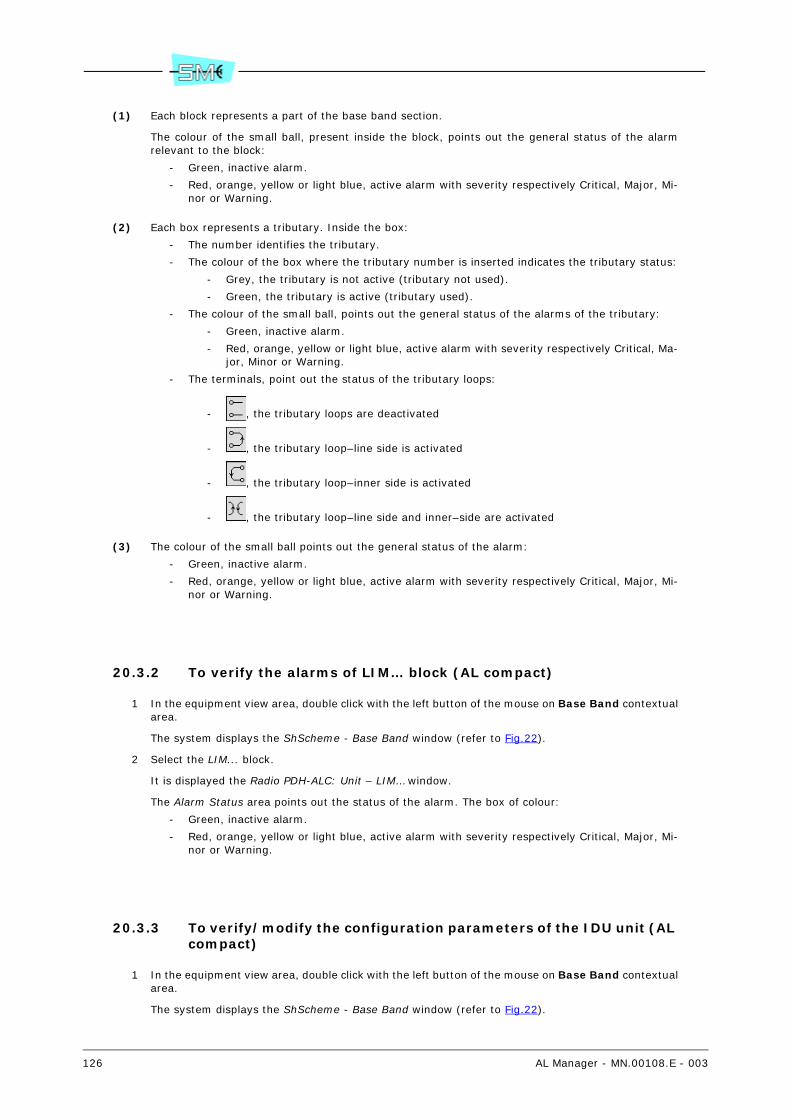
126 AL Manager - MN.00108.E - 003
(1) Each block represents a part of the base band section.
The colour of the small ball, present inside the block, points out the general status of the alarmrelevant to the block:
- Green, inactive alarm.
- Red, orange, yellow or light blue, active alarm with severity respectively Critical, Major, Mi-nor or Warning.
(2) Each box represents a tributary. Inside the box:
- The number identifies the tributary.
- The colour of the box where the tributary number is inserted indicates the tributary status:
- Grey, the tributary is not active (tributary not used).
- Green, the tributary is active (tributary used).
- The colour of the small ball, points out the general status of the alarms of the tributary:
- Green, inactive alarm.
- Red, orange, yellow or light blue, active alarm with severity respectively Critical, Ma-jor, Minor or Warning.
- The terminals, point out the status of the tributary loops:
- , the tributary loops are deactivated
- , the tributary loop–line side is activated
- , the tributary loop–inner side is activated
- , the tributary loop–line side and inner–side are activated
(3) The colour of the small ball points out the general status of the alarm:
- Green, inactive alarm.
- Red, orange, yellow or light blue, active alarm with severity respectively Critical, Major, Mi-nor or Warning.
20.3.2 To verify the alarms of LIM… block (AL compact)
1 In the equipment view area, double click with the left button of the mouse on Base Band contextualarea.
The system displays the ShScheme - Base Band window (refer to Fig.22).
2 Select the LIM... block.
It is displayed the Radio PDH-ALC: Unit – LIM… window.
The Alarm Status area points out the status of the alarm. The box of colour:
- Green, inactive alarm.
- Red, orange, yellow or light blue, active alarm with severity respectively Critical, Major, Mi-nor or Warning.
20.3.3 To verify/modify the configuration parameters of the IDU unit (AL compact)
1 In the equipment view area, double click with the left button of the mouse on Base Band contextualarea.
The system displays the ShScheme - Base Band window (refer to Fig.22).
AL Manager - MN.00108.E - 003 127
2 Into the Unit List area, select the IDU unit.
It is displayed the Radio PDH-ALC: Unit – <unit name> window.
The box:
- Expected Type. Expected unit type.
A difference between the really present unit (Label parameter) and the expected one acti-vates an alarm (Unit Hw Mismatch Alarm).
The Unequipped wording points out that the unit is not equipped.
- Label. Unit type really present into the equipment.
The Unequipped wording points out that the unit is not physically present into the equip-ment.
- Hardware Edition. Unit version.
- Part Number. Unit Part Number.
- Parent Part Number. Part number of the group that contains the unit.
Usually, the group represents the part of the equipment that can be replaced.
Warning. Not all the units are included into a group. In this case, the field will result emptyand the part of the equipment that can be replaced will correspond to the unit itself.
- Serial Number. The serial number of the group that contains the unit.
Warning. If the unit is not contained into a group (the Parent Part Number field is empty),the Serial Number refers to the unit.
The Alarm Status area points out the status of the unit alarm. The box of colour:
- Green, inactive alarm.
- Red, orange, yellow or light blue, active alarm with severity respectively Critical, Major, Mi-nor or Warning.
3 To check the currently set value in the equipment, select twice quickly on the parameter name andselect the Get push-button or the Commands – Send GET Request command.
4 To change the Hardware Edition and/or Part Number parameter:
a Type into the relevant box an alphanumeric string with a minimum of 1 and a maximum of20 characters (Hardware Edition) and minimum of 1 and a maximum of 30 characters (PartNumber).
b Select the Set push-button or the Commands – Send SET Request command.
20.3.4 To activate/deactivate the tributaries use (AL compact)
1 In the equipment view area, double click with the left button of the mouse on Base Band contextualarea.
The system displays the ShScheme - Base Band window (refer to Fig.22).
2 Double click with the left button of the mouse on the tributary to be enabled (or disabled).
The system displays the Radio PDH-ALC: Unit PDH_AL Physical interface... window
The Enable parameter, points out the tributary use:
- Enable, tributary used.
- Disable, tributary not used.
3 To check the currently set value in the equipment, select twice quickly on the parameter name andselect the Get push-button or the Commands – Send GET Request command.
4 To change the parameter:
a Select the box where it is pointed out the value.
b Choose the new value from the list.
c Select the Set push-button or the Commands – Send SET Request command.
128 AL Manager - MN.00108.E - 003
20.3.5 To activate/deactivate the tributary line side loops (AL compact)
1 In the equipment view area, double click with the left button of the mouse on Base Band contextualarea.
The system displays the ShScheme - Base Band window (refer to Fig.22).
2 Double click with the left button of the mouse on the tributary to be enabled (or disabled).
The system displays the Radio PDH-ALC: Unit PDH_AL Physical interface... window
The Line Loop parameter, points out the status of tributary line side loop:
- Loop Off, the loop is deactivated (default setting).
- Loop On, the loop is activated (activation of the manual operation).
3 To check the currently set value in the equipment, select twice quickly on the parameter name andselect the Get push-button or the Commands – Send GET Request command.
4 To change the parameter:
a Select the box where it is pointed out the value.
b Choose the new value from the list.
c Select the Set push-button or the Commands – Send SET Request command.
It is displayed the confirm window.
Warning. Only if you are activating loop (selection of the Loop On value) a message is dis-played warning that you are executing a forcing and displaying the current setting of timeout41.
d Select the Ok push-button.
The activating of the loop activates the MAN. OP alarm. If the equipment is switched offand, then, switched on, the transmitter is on, independently from the previous setting.
20.3.6 To activate/deactivate the tributary internal side loops (AL com-pact)
1 In the equipment view area, double click with the left button of the mouse on Base Band contextualarea.
The system displays the ShScheme - Base Band window (refer to Fig.22).
2 Double click with the left button of the mouse on the tributary to be enabled (or disabled).
The system displays the Radio PDH-ALC: Unit PDH_AL Physical interface... window
The Internal Loop parameter, points out the status of tributary internal side loop:
- Loop Off, the loop is deactivated (default setting).
- Loop On, the loop is activated (activation of the manual operation).
3 To check the currently set value in the equipment, select twice quickly on the parameter name andselect the Get push-button or the Commands – Send GET Request command.
4 To change the parameter:
a Select the box where it is pointed out the value.
b Choose the new value from the list.
c Select the Set push-button or the Commands – Send SET Request command.
It is displayed the confirm window.
Warning. Only if you are activating loop (selection of the Loop On value) a message is dis-played warning that you are executing a forcing and displaying the current setting of timeout41.
d Select the Ok push-button.
The activating of the loop activates the MAN. OP alarm. If the equipment is switched offand, then, switched on, the transmitter is on, independently from the previous setting.

AL Manager - MN.00108.E - 003 129
20.3.7 To verify/modify the name of the tributary (AL compact)
1 In the equipment view area, double click with the left button of the mouse on Base Band contextualarea.
The system displays the ShScheme - Base Band window (refer to Fig.22).
2 Double click with the left button of the mouse on the tributary to be enabled (or disabled).
The system displays the Radio PDH-ALC: Unit PDH_AL Physical interface... window
The Label parameter, points out the name of tributary.
3 To check the currently set value in the equipment, select twice quickly on the parameter name andselect the Get push-button or the Commands – Send GET Request command.
4 To change the parameter:
a Type in the text box the new name.
b Select the Set push-button or the Commands – Send SET Request command.
20.4 AL equipment version 2 units with 32x2Mbit/s capacity
The Base Band contextual area, for the AL equipment version 2 units with 32x2Mb/s capacity, allows to:
- To verify the tributary status (AL 2U 32x2Mbit/s) (par. 20.4.1)
- To verify the alarms of LIM… block (AL 2U 32x2Mbit/s) (par. 20.4.2)
- To verify/modify the configuration parameters of LIM unit (AL 2U 32x2Mbit/s) (par. 20.4.3)
- To activate/deactivate the tributaries use (AL 2U 32x2Mbit/s) (par. 20.4.4)
- To activate/deactivate the tributary line side loops (AL 2U 32x2Mbit/s) (par. 20.4.5)
- To activate/deactivate the tributary internal side loops (AL 2U 32x2Mbit/s) (par. 20.4.6)
20.4.1 To verify the tributary status (AL 2U 32x2Mbit/s)
1 In the equipment view area, double click with the left button of the mouse on Base Band - LIM 1or Base Band - LIM 2 contextual area.
The first choice opens the Radio PDH-AL: Subrack - Base Band - LIM 1 window, where the status ofthe tributaries of the LIM 1 section is displayed, as depicted in Fig.23.
The second choice opens the Radio PDH-AL: Subrack - Base Band - LIM 2 window, where the statusof the tributaries of the LIM 2 section is displayed, as depicted in Fig.24.

130 AL Manager - MN.00108.E - 003
Fig.23 - Radio PDH-AL: Subrack - Base Band - LIM 1 window (AL 2U 32x2Mbit/s)
Functionalblock diagram
of theequipment (1)
List of thebase band
units
Unit name Status of the unit alarms (3)
Tributariesavailable for theequipment (2)

AL Manager - MN.00108.E - 003 131
Fig.24 - Radio PDH-AL: Subrack - Base Band - LIM 2 window (AL 2U 32x2Mbit/s)
Fig.23 and Fig.24 notes
(1) Each block represents a part of the base band section.
The colour of the small ball, present inside the block, points out the general status of the alarmrelevant to the block:
- Green, inactive alarm.
- Red, orange, yellow or light blue, active alarm with severity respectively Critical, Major, Mi-nor or Warning.
Warning. The scheme changes according to the configuration (1+0 or 1+1) of the equipment.
(2) Each box represents a tributary. Inside the box:
- The number identifies the tributary.
- The colour of the box where the tributary number is inserted indicates the tributary status:
- Grey, the tributary is not active (tributary not used). In this case, the alarms are in-hibited and LOS alarm becomes active if, with tributary disabled, the 2Mbit/s signalis however connected.
- Green, the tributary is active (tributary used). In this case, the controller does notinhibit.
- The colour of the small ball, points out the general status of the alarms of the tributary:
- Green, inactive alarm.
- Red, orange, yellow or light blue, active alarm with severity respectively Critical, Ma-jor, Minor or Warning.
- The terminals, point out the status of the tributary loops:
- , the tributary loops are deactivated
- , the tributary loop–line side is activated
- , the tributary loop–inner side is activated
Functionalblock diagram
of theequipment (1)
List of thebase band
units
Unit name Status of the unit alarms (3)
Tributariesavailable for
the equipment(2)

132 AL Manager - MN.00108.E - 003
- , the tributary loop–line side and inner–side are activated
Warning. The number of tributaries changes depending on the equipment capacity.
(3) The colour of the small ball points out the general status of the alarm:
- Green, inactive alarm.
- Red, orange, yellow or light blue, active alarm with severity respectively Critical, Major, Mi-nor or Warning.
20.4.2 To verify the alarms of LIM… block (AL 2U 32x2Mbit/s)
1 In the equipment view area, double click with the left button of the mouse on Base Band - LIM 1or Base Band - LIM 2 contextual area.
The system displays the Radio PDH-AL: Subrack – Base Band - LIM 1 window (refer to Fig.23) orRadio PDH-AL: Subrack – Base Band - LIM 2 window (refer to Fig.24).
2 Select the LIM... block.
It is displayed the Radio PDH-AL: Unit – LIM… window.
The Alarm Status area points out the status of the alarm. The box of colour:
- Green, inactive alarm.
- Red, orange, yellow or light blue, active alarm with severity respectively Critical, Major, Mi-nor or Warning.
20.4.3 To verify/modify the configuration parameters of the LIM unit (AL 2U 32x2Mbit/s)
1 In the equipment view area, double click with the left button of the mouse on Base Band - LIM 1or Base Band - LIM 2 contextual area.
The system displays the Radio PDH-AL: Subrack – Base Band - LIM 1 window (refer to Fig.23) orRadio PDH-AL: Subrack – Base Band - LIM 2 window (refer to Fig.24).
2 Into the Unit List area, select the LIM... unit.
It is displayed the Radio PDH-AL: Unit – <unit name> window.
The box:
- Expected Type. Expected unit type.
A difference between the really present unit (Label parameter) and the expected one acti-vates an alarm (Unit Hw Mismatch Alarm).
The Unequipped wording points out that the unit is not equipped.
- Label. Unit type really present into the equipment.
The Unequipped wording points out that the unit is not physically present into the equip-ment.
- Hardware Edition. Unit version.
- Part Number. Unit Part Number.
- Parent Part Number. Part number of the group that contains the unit.
Usually, the group represents the part of the equipment that can be replaced.
Warning. Not all the units are included into a group. In this case, the field will result emptyand the part of the equipment that can be replaced will correspond to the unit itself.
- Serial Number. The serial number of the group that contains the unit.
Warning. If the unit is not contained into a group (the Parent Part Number field is empty),the Serial Number refers to the unit.

AL Manager - MN.00108.E - 003 133
The Alarm Status area points out the status of the unit alarm. The box of colour:
- Green, inactive alarm.
- Red, orange, yellow or light blue, active alarm with severity respectively Critical, Major, Mi-nor or Warning.
3 To check the currently set value in the equipment, select twice quickly on the parameter name andselect the Get push-button or the Commands – Send GET Request command.
4 To change the Hardware Edition and/or Part Number parameter:
a Type into the relevant box an alphanumeric string with a minimum of 1 and a maximum of20 characters (Hardware Edition) and minimum of 1 and a maximum of 30 characters (PartNumber).
b Select the Set push-button or the Commands – Send SET Request command.
20.4.4 To activate/deactivate the tributaries use (AL 2U 32x2Mbit/s)
1 In the equipment view area, double click with the left button of the mouse on Base Band - LIM 1or Base Band - LIM 2 contextual area.
The system displays the Radio PDH-AL: Subrack – Base Band - LIM 1 window (refer to Fig.23) orRadio PDH-AL: Subrack – Base Band - LIM 2 window (refer to Fig.24).
2 Double click with the left button of the mouse on the tributary to be enabled (or disabled).
The system displays the Radio PDH-AL: Unit PDH_AL Physical interface... window
The Enable parameter, points out the tributary use:
- Enable, tributary used.
- Disable, tributary not used.
3 To check the currently set value in the equipment, select twice quickly on the parameter name andselect the Get push-button or the Commands – Send GET Request command.
4 To change the parameter:
a Select the box where it is pointed out the value.
b Choose the new value from the list.
c Select the Set push-button or the Commands – Send SET Request command.
20.4.5 To activate/deactivate the tributary line side loops (AL 2U 32x2Mbit/s)
1 In the equipment view area, double click with the left button of the mouse on Base Band - LIM 1or Base Band - LIM 2 contextual area.
The system displays the Radio PDH-AL: Subrack – Base Band - LIM 1 window (refer to Fig.23) orRadio PDH-AL: Subrack – Base Band - LIM 2 window (refer to Fig.24).
2 Double click with the left button of the mouse on the tributary to be enabled (or disabled).
The system displays the Radio PDH-AL: Unit PDH_AL Physical interface... window
The Line Loop parameter, points out the status of tributary line side loop:
- Loop Off, the loop is deactivated (default setting).
- Loop On, the loop is activated (activation of the manual operation).
3 To check the currently set value in the equipment, select twice quickly on the parameter name andselect the Get push-button or the Commands – Send GET Request command.
4 To change the parameter:
a Select the box where it is pointed out the value.

134 AL Manager - MN.00108.E - 003
b Choose the new value from the list.
c Select the Set push-button or the Commands – Send SET Request command.
It is displayed the confirm window.
Warning. Only if you are activating loop (selection of the Loop On value) a message is dis-played warning that you are executing a forcing and displaying the current setting of timeout41.
d Select the Ok push-button.
The activating of the loop activates the MAN. OP alarm. If the equipment is switched offand, then, switched on, the transmitter is on, independently from the previous setting.
20.4.6 To activate/deactivate the tributary internal side loops (AL 2U 32x2Mbit/s)
1 In the equipment view area, double click with the left button of the mouse on Base Band - LIM 1or Base Band - LIM 2 contextual area.
The system displays the Radio PDH-AL: Subrack – Base Band - LIM 1 window (refer to Fig.23) orRadio PDH-AL: Subrack – Base Band - LIM 2 window (refer to Fig.24).
2 Double click with the left button of the mouse on the tributary to be enabled (or disabled).
The system displays the Radio PDH-AL: Unit PDH_AL Physical interface... window
The Internal Loop parameter, points out the status of tributary internal side loop:
- Loop Off, the loop is deactivated (default setting).
- Loop On, the loop is activated (activation of the manual operation).
3 To check the currently set value in the equipment, select twice quickly on the parameter name andselect the Get push-button or the Commands – Send GET Request command.
4 To change the parameter:
a Select the box where it is pointed out the value.
b Choose the new value from the list.
c Select the Set push-button or the Commands – Send SET Request command.
It is displayed the confirm window.
Warning. Only if you are activating loop (selection of the Loop On value) a message is dis-played warning that you are executing a forcing and displaying the current setting of timeout41.
d Select the Ok push-button.
The activating of the loop activates the MAN. OP alarm. If the equipment is switched offand, then, switched on, the transmitter is on, independently from the previous setting.
20.5 AL equipment version 2 units Terminal 16x2 East-West
The Base Band contextual area, for the AL equipment version 2 units Terminal 16x2 East-West, allows to:
- To verify the tributary status (AL 2U 16x2 E-W) (par. 20.5.1)
- To verify the alarms of LIM… block (AL 2U 16x2 E-W) (par. 20.5.2)
- To verify/modify the configuration parameters of LIM unit (AL 2U 16x2 E-W) (par. 20.5.3)
- To activate/deactivate the tributaries use (AL 2U 16x2 E-W) (par. 20.5.4)
- To activate/deactivate the tributary line side loops (AL 2U 16x2 E-W) (par. 20.5.5)
- To activate/deactivate the tributary internal side loops (AL 2U 16x2 E-W) (par. 20.5.6)
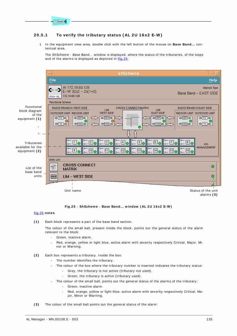
AL Manager - MN.00108.E - 003 135
20.5.1 To verify the tributary status (AL 2U 16x2 E-W)
1 In the equipment view area, double click with the left button of the mouse on Base Band... con-textual area.
The ShScheme - Base Band... window is displayed, where the status of the tributaries, of the loopsand of the alarms is displayed as depicted in Fig.25.
Fig.25 - ShScheme - Base Band... window (AL 2U 16x2 E-W)
Fig.25 notes
(1) Each block represents a part of the base band section.
The colour of the small ball, present inside the block, points out the general status of the alarmrelevant to the block:
- Green, inactive alarm.
- Red, orange, yellow or light blue, active alarm with severity respectively Critical, Major, Mi-nor or Warning.
(2) Each box represents a tributary. Inside the box:
- The number identifies the tributary.
- The colour of the box where the tributary number is inserted indicates the tributary status:
- Grey, the tributary is not active (tributary not used).
- Green, the tributary is active (tributary used).
- The colour of the small ball, points out the general status of the alarms of the tributary:
- Green, inactive alarm.
- Red, orange, yellow or light blue, active alarm with severity respectively Critical, Ma-jor, Minor or Warning.
(3) The colour of the small ball points out the general status of the alarm:
Functionalblock diagram
of theequipment (1)
List of thebase band
units
Unit name Status of the unitalarms (3)
Tributariesavailable for theequipment (2)

136 AL Manager - MN.00108.E - 003
- Green, inactive alarm.
- Red, orange, yellow or light blue, active alarm with severity respectively Critical, Major, Mi-nor or Warning.
20.5.2 To verify the alarms of LIM… block (AL 2U 16x2 E-W)
1 In the equipment view area, double click with the left button of the mouse on Base Band... con-textual area.
The system displays the ShScheme - Base Band... window (refer to Fig.25).
2 Select the LIM... block.
It is displayed the Radio PDH-AL: Unit – LIM… window.
The Alarm Status area points out the status of the alarm. The box of colour:
- Green, inactive alarm.
- Red, orange, yellow or light blue, active alarm with severity respectively Critical, Major, Mi-nor or Warning.
20.5.3 To verify/modify the configuration parameters of the LIM unit (AL 2U 16x2 E-W)
1 In the equipment view area, double click with the left button of the mouse on Base Band... con-textual area.
The system displays the ShScheme - Base Band... window (refer to Fig.25).
2 Into the Unit List area, select the LIM... unit.
It is displayed the Radio PDH-AL: Unit – <unit name> window.
The box:
- Expected Type. Expected unit type.
A difference between the really present unit (Label parameter) and the expected one acti-vates an alarm (Unit Hw Mismatch Alarm).
The Unequipped wording points out that the unit is not equipped.
- Label. Unit type really present into the equipment.
The Unequipped wording points out that the unit is not physically present into the equip-ment.
- Hardware Edition. Unit version.
- Part Number. Unit Part Number.
- Parent Part Number. Part number of the group that contains the unit.
Usually, the group represents the part of the equipment that can be replaced.
Warning. Not all the units are included into a group. In this case, the field will result emptyand the part of the equipment that can be replaced will correspond to the unit itself.
- Serial Number. The serial number of the group that contains the unit.
Warning. If the unit is not contained into a group (the Parent Part Number field is empty),the Serial Number refers to the unit.
The Alarm Status area points out the status of the unit alarm. The box of colour:
- Green, inactive alarm.
- Red, orange, yellow or light blue, active alarm with severity respectively Critical, Major, Mi-nor or Warning.
3 To check the currently set value in the equipment, select twice quickly on the parameter name andselect the Get push-button or the Commands – Send GET Request command.
4 To change the Hardware Edition and/or Part Number parameter:

AL Manager - MN.00108.E - 003 137
a Type into the relevant box an alphanumeric string with a minimum of 1 and a maximum of20 characters (Hardware Edition) and minimum of 1 and a maximum of 30 characters (PartNumber).
b Select the Set push-button or the Commands – Send SET Request command.
20.5.4 To activate/deactivate the tributaries use (AL 2U 16x2 E-W)
1 In the equipment view area, double click with the left button of the mouse on Base Band... con-textual area.
The system displays the ShScheme - Base Band... window (refer to Fig.25).
2 Double click with the left button of the mouse on the tributary to be enabled (or disabled).
The system displays the Radio PDH-AL: Unit PDH_AL Physical interface... window
The Enable parameter, points out the tributary use:
- Enable, tributary used.
- Disable, tributary not used.
3 To check the currently set value in the equipment, select twice quickly on the parameter name andselect the Get push-button or the Commands – Send GET Request command.
4 To change the parameter:
a Select the box where it is pointed out the value.
b Choose the new value from the list.
c Select the Set push-button or the Commands – Send SET Request command.
20.5.5 To activate/deactivate the tributary line side loops (AL 2U 16x2 E-W)
1 In the equipment view area, double click with the left button of the mouse on Base Band... con-textual area.
The system displays the ShScheme - Base Band... window (refer to Fig.25).
2 Double click with the left button of the mouse on the tributary to be enabled (or disabled).
The system displays the Radio PDH-AL: Unit PDH_AL Physical interface... window
The Line Loop parameter, points out the status of tributary line side loop:
- Loop Off, the loop is deactivated (default setting).
- Loop On, the loop is activated (activation of the manual operation).
3 To check the currently set value in the equipment, select twice quickly on the parameter name andselect the Get push-button or the Commands – Send GET Request command.
4 To change the parameter:
a Select the box where it is pointed out the value.
b Choose the new value from the list.
c Select the Set push-button or the Commands – Send SET Request command.
It is displayed the confirm window.
Warning. Only if you are activating loop (selection of the Loop On value) a message is dis-played warning that you are executing a forcing and displaying the current setting of timeout41.
d Select the Ok push-button.
The activating of the loop activates the MAN. OP alarm. If the equipment is switched offand, then, switched on, the transmitter is on, independently from the previous setting.

138 AL Manager - MN.00108.E - 003
20.5.6 To activate/deactivate the tributary internal side loops (AL 2U 16x2 E-W)
1 In the equipment view area, double click with the left button of the mouse on Base Band contextualarea.
The system displays the ShScheme - Base Band... window (refer to Fig.25).
2 Double click with the left button of the mouse on the tributary to be enabled (or disabled).
The system displays the Radio PDH-AL: Unit PDH_AL Physical interface... window
The Internal Loop parameter, points out the status of tributary internal side loop:
- Loop Off, the loop is deactivated (default setting).
- Loop On, the loop is activated (activation of the manual operation).
3 To check the currently set value in the equipment, select twice quickly on the parameter name andselect the Get push-button or the Commands – Send GET Request command.
4 To change the parameter:
a Select the box where it is pointed out the value.
b Choose the new value from the list.
c Select the Set push-button or the Commands – Send SET Request command.
It is displayed the confirm window.
Warning. Only if you are activating loop (selection of the Loop On value) a message is dis-played warning that you are executing a forcing and displaying the current setting of timeout41.
d Select the Ok push-button.
The activating of the loop activates the MAN. OP alarm. If the equipment is switched off and,then, switched on, the transmitter is on, independently from the previous setting.
AL Manager - MN.00108.E - 003 139
21 CROSS CONNECT MATRIX (CONTEXTUAL AREA)
Warning. The Cross Connect Matrix contextual area is available only for AL radio equipment Terminal16x2 East-West type.
The Cross Connect matrix contextual area, allows to:
- To check the equipment cross connections 74 (par. 21.1)
- To execute a not protected tributary-aggregate connection ( or 75) (par.21.2)
- To execute a protected tributary-aggregate connection ( 75) (par. 21.3)
- To execute an aggregate-aggregate connection (pass through) ( 75) (par. 21.4)
- To delete a connection (par. 21.5)
- Enable the closing of an E1 on itself (loop) (par. 21.6)
- Disable the closing of an E1 on itself (loop) (par. 21.7)
Warning. The following operations are available only for the protected tributary-aggregate connections.
- To verify the status of a protected connection: main and standby (par. 21.8)
- To verify/modify the mode used for the switching management: automatic or forced (par. 21.9)
- To verify/modify the mode used for the management of the “preferential connection” 76 (par.21.10)
21.1 To check the equipment cross connections
1 In the equipment view area, double click with the left button of the mouse on Cross Connect Ma-trix.
It is displayed the ShScheme window.
2 Double click with the left button of the mouse on Cross Connect Matrix block.
The ShCross window depicted in Fig.26 opens, where it is possible to check the existing connections.
3 To display a connection, point with the mouse:
- The 2Mbit/s used for the connection you wish to check. If the following items are highlighted:a 2Mbit/s tributary and an E1 aggregate linked by a blue line, this means that the connectionis of unprotected tributary-aggregate type.
- The 2Mbit/s used for the connection you wish to check. If the following items are highlighted:a 2Mbit/s tributary and an E1 aggregate linked by a blue line, the same 2Mbit/s tributary anda different aggregate E1 linked by a pink line, this means that the connection is of protectedtributary-aggregate type.
74 Warning. The change of the base band type removes all the connections of the equipment.
75 W: E1 aggregate on west side. E: E1 aggregate on East side. T: 2Mbit/s Tributary.
76 The function of “preferential connection” allows choosing a connection to use in prioritary way when ithas no alarms that require a switch. In automatic mode, the system uses for the operation the connectionthat does not show alarms, with parity of condition, it keeps the connection on service. Selecting a prefer-ential connection, the switching will be positioned on the chosen connection every time it will exit from analarm condition.
W T T E
W T E
W E
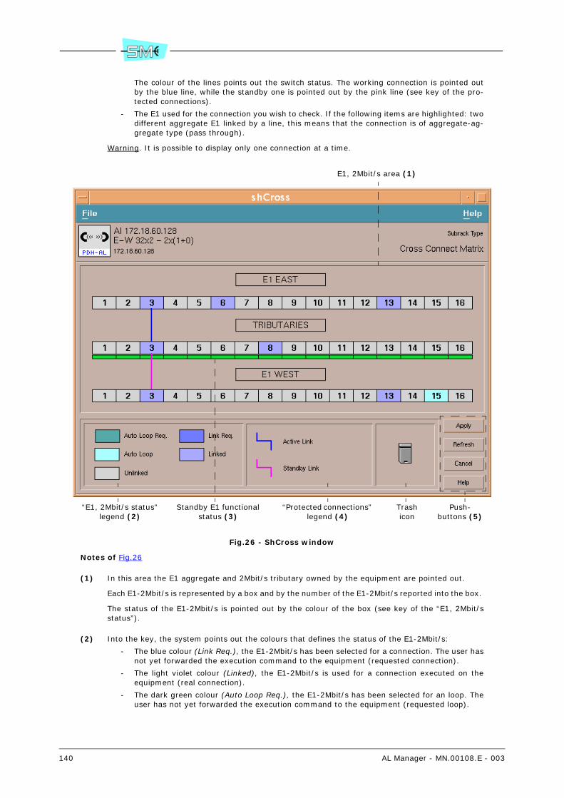
140 AL Manager - MN.00108.E - 003
The colour of the lines points out the switch status. The working connection is pointed outby the blue line, while the standby one is pointed out by the pink line (see key of the pro-tected connections).
- The E1 used for the connection you wish to check. If the following items are highlighted: twodifferent aggregate E1 linked by a line, this means that the connection is of aggregate-ag-gregate type (pass through).
Warning. It is possible to display only one connection at a time.
Fig.26 - ShCross window
Notes of Fig.26
(1) In this area the E1 aggregate and 2Mbit/s tributary owned by the equipment are pointed out.
Each E1-2Mbit/s is represented by a box and by the number of the E1-2Mbit/s reported into the box.
The status of the E1-2Mbit/s is pointed out by the colour of the box (see key of the “E1, 2Mbit/sstatus”).
(2) Into the key, the system points out the colours that defines the status of the E1-2Mbit/s:
- The blue colour (Link Req.), the E1-2Mbit/s has been selected for a connection. The user hasnot yet forwarded the execution command to the equipment (requested connection).
- The light violet colour (Linked), the E1-2Mbit/s is used for a connection executed on theequipment (real connection).
- The dark green colour (Auto Loop Req.), the E1-2Mbit/s has been selected for an loop. Theuser has not yet forwarded the execution command to the equipment (requested loop).
E1, 2Mbit/s area (1)
“E1, 2Mbit/s status” legend (2)
“Protected connections” legend (4)
Push-buttons (5)
Trashicon
Standby E1 functional status (3)
AL Manager - MN.00108.E - 003 141
- The light green colour (Auto Loop), the E1-2Mbit/s is used for an loop executed on the equip-ment (real loop).
- - The grey colour (Unlinked), the E1-2Mbit/s is not used.
(3) The colour of the box points out the functional status of the E1 used for a protected tributary-ag-gregate connection. The status of E1 is meaningful only for the stand-by connection.
- The green colour, the standby E1 has not been alarmed.
- The light blue colour, the standby E1 has been alarmed (Warning gravity).
- The yellow colour, the standby E1 has been alarmed (Minor gravity).
- The orange colour, the standby E1 has been alarmed (Major gravity).
- The red colour, the standby E1 has been alarmed (Critical gravity).
(4) In case of protected connections, the colour line:
- Blue, points out the currently used connection (active connection).
- Pink, points out the unused connection (standby connection).
(5) If changes are made to the connections (adding, removal, etc.), on the choice of the push-button:
- Apply a confirmation message is displayed. Selecting the Ok push-button, all the changesmade on the cross connection matrix are communicated to the controller. Selecting the Can-cel push-button, the operation is not executed.
- Refresh, the data present are updated in the window and all the changes made to the con-nections are lost.
- Cancel a confirmation message is displayed. Selecting the Ok push-button, the operation isexecuted and all the changes made to the connections are lost. Selecting the Cancel push-button, the operation is not executed.
The Help push-button opens the manual.
21.2 To execute a not protected tributary-aggregate connection
1 In the equipment view area, double click with the left button of the mouse on Cross Connect Ma-trix.
It is displayed the ShScheme window.
2 Double click with the left button of the mouse on Cross Connect Matrix block.
It is displayed the ShCross window (refer to Fig.26).
3 Select the unused 2Mbit/s on tributary side and drag it over the unused E1 on aggregate side (westor east) (or vice versa) you wish to use for the connection.
The two boxes are linked by a blue line.
4 Press Apply.
The system displays a confirmation window.
5 Press Ok.
Warning. The choice of the Ok push-button make effective all the changes executed on the cross-connection matrix.

142 AL Manager - MN.00108.E - 003
21.3 To execute a protected tributary-aggregate connection
1 In the equipment view area, double click with the left button of the mouse on Cross Connect Ma-trix.
It is displayed the ShScheme window.
2 Double click with the left button of the mouse on Cross Connect Matrix block.
It is displayed the ShCross window (refer to Fig.26).
3 Select the unused 2Mbit/s on tributary side and drag it over the unused E1 on aggregate side (westor east) (o vice versa) you wish to use for a "branch" of the connection.
The two boxes are linked by a blue line.
4 Select the same 2Mbit/s on tributary side selected in the previous step and drag it over the unusedE1 on aggregate side 58 (west or east) you wish to use for the second "branch" of the connection.
The two boxes are linked by a pink line.
Warning. If in the previous step a E1 of west aggregate, for example, has been selected, for thesecond branch of the connection it is necessary to select a E1 of the east aggregate.
5 Press Apply.
The system displays a confirmation window.
6 Press Ok.
Warning. The choice of the Ok push-button make effective all the changes executed on the cross-connection matrix.
21.4 To execute an aggregate-aggregate connection (pass through)
1 In the equipment view area, double click with the left button of the mouse on Cross Connect Ma-trix.
It is displayed the ShScheme window.
2 Double click with the left button of the mouse on Cross Connect Matrix block.
It is displayed the ShCross window (refer to Fig.26).
3 Select the unused E1 on west aggregate side and drag it over the unused E1 on east aggregate side(or vice-versa) you wish to use for the connection.
The two boxes are linked by a blue line.
4 Press Apply.
The system displays a confirmation window.
5 Press Ok.
Warning. The choice of the Ok push-button make effective all the changes executed on the cross-connection matrix.

AL Manager - MN.00108.E - 003 143
21.5 To delete a connection
1 In the equipment view area, double click with the left button of the mouse on Cross Connect Ma-trix.
It is displayed the ShScheme window.
2 Double click with the left button of the mouse on Cross Connect Matrix block.
It is displayed the ShCross window (refer to Fig.26).
3 Select one of the E1-2Mbit/s of the connection you wish to delete and drag it on the trash icon.
A confirmation window opens.
4 Press the Ok push-button to delete the connection.
5 Press Apply.
The system displays a confirmation window.
6 Press Ok.
Warning. The choice of the Ok push-button make effective all the changes executed on the cross-connection matrix.
21.6 To enable the re-closure of an E1 on itself (loop)
1 In the equipment view area, double click with the left button of the mouse on Cross Connect Ma-trix.
It is displayed the ShScheme window.
2 Double click with the left button of the mouse on Cross Connect Matrix block.
It is displayed the ShCross window (refer to Fig.26).
3 Select the E1 not used on aggregate east or west side and drag over itself.
4 Press Apply.
The system displays a confirmation window.
5 Press Ok.
Warning. The choice of the Ok push-button make effective all the changes executed on the cross-connection matrix.
21.7 To disable the re-closure of an E1 on itself (loop)
1 In the equipment view area, double click with the left button of the mouse on Cross Connect Ma-trix.
It is displayed the ShScheme window.
2 Double click with the left button of the mouse on Cross Connect Matrix block.
It is displayed the ShCross window (refer to Fig.26).
3 Select the E1 with loop active (box of light blue color) and drag over the Trash icon.
A confirmation window opens.
4 Press Ok.
144 AL Manager - MN.00108.E - 003
5 Press Apply.
The system displays a confirmation window.
6 Press Ok.
Warning. The choice of the Ok push-button make effective all the changes executed on the cross-connection matrix.
21.8 To verify the status of a protected connection: main and stand-by
1 In the equipment view area, double click with the left button of the mouse on Cross Connect Ma-trix.
It is displayed the ShScheme window.
2 Double click with the left button of the mouse on Cross Connect Matrix block.
It is displayed the ShCross window (refer to Fig.26).
3 It is possible to verify the status of a protected connection:
- Moving the mouse pointer over the 2Mbit/s of the wished connection.
The connection is highlighted showing the active connection (blue line) and the standby one(pink line).
- By means of a double click over the 2Mbit/s tributary side of the wished connection.
The Path Protection Policy window opens.
In the Switch Status area, the active connection (blue line) and the standby one (pink line)are displayed as depicted in Fig.27.
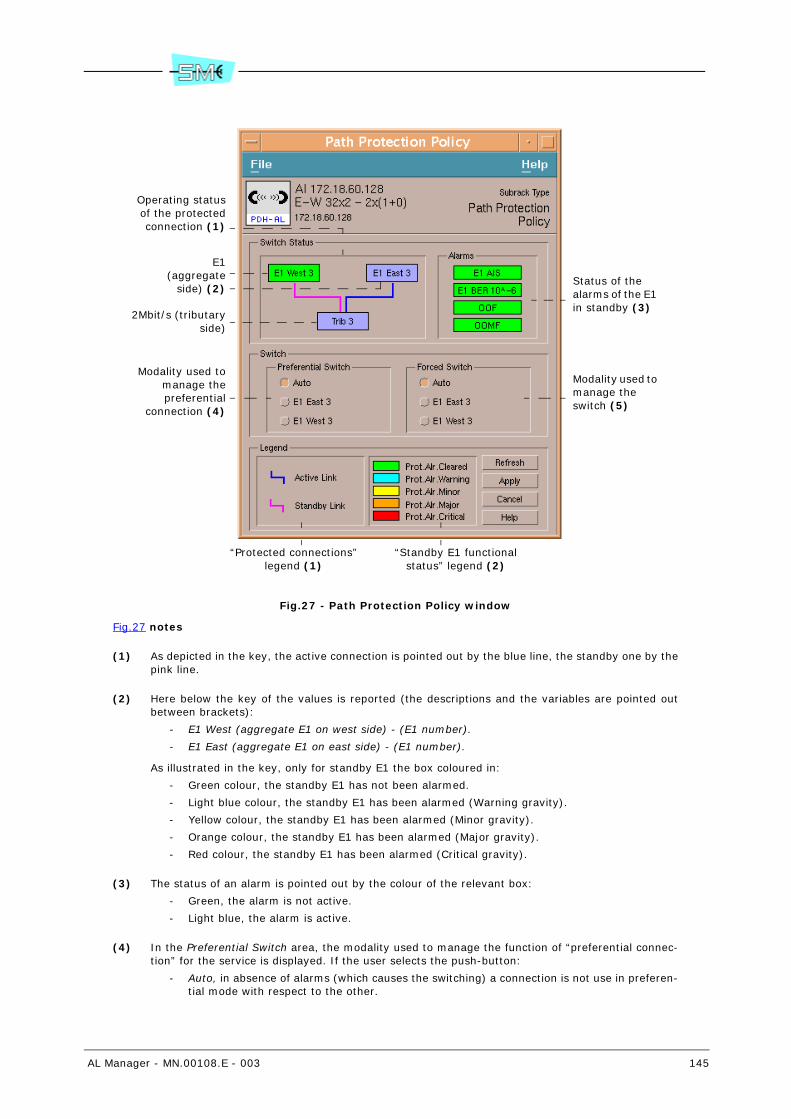
AL Manager - MN.00108.E - 003 145
Fig.27 - Path Protection Policy window
Fig.27 notes
(1) As depicted in the key, the active connection is pointed out by the blue line, the standby one by thepink line.
(2) Here below the key of the values is reported (the descriptions and the variables are pointed outbetween brackets):
- E1 West (aggregate E1 on west side) - (E1 number).
- E1 East (aggregate E1 on east side) - (E1 number).
As illustrated in the key, only for standby E1 the box coloured in:
- Green colour, the standby E1 has not been alarmed.
- Light blue colour, the standby E1 has been alarmed (Warning gravity).
- Yellow colour, the standby E1 has been alarmed (Minor gravity).
- Orange colour, the standby E1 has been alarmed (Major gravity).
- Red colour, the standby E1 has been alarmed (Critical gravity).
(3) The status of an alarm is pointed out by the colour of the relevant box:
- Green, the alarm is not active.
- Light blue, the alarm is active.
(4) In the Preferential Switch area, the modality used to manage the function of “preferential connec-tion” for the service is displayed. If the user selects the push-button:
- Auto, in absence of alarms (which causes the switching) a connection is not use in preferen-tial mode with respect to the other.
Operating statusof the protectedconnection (1)
E1(aggregate
side) (2)
2Mbit/s (tributaryside)
Modality used tomanage thepreferential
connection (4)
“Protected connections” legend (1)
“Standby E1 functional status” legend (2)
Status of the alarms of the E1 in standby (3)
Modality used to manage the switch (5)
146 AL Manager - MN.00108.E - 003
- E1 West…, in absence of alarms (which causes the switching) the system uses as preferentialthe connection with the aggregate E1 on west side pointed out by the label of the push-but-ton.
- E1 East…, in absence of alarms (which causes the switching) the system uses as preferentialthe connection with the aggregate E1 on east side pointed out by the label of the push-but-ton.
(5) In the Forced Switch area, the modality used to manage the switch between the active connectionand the standby connection is displayed. If the user selects the push-button:
- Auto, the switch is managed automatically according to the presence of alarms (normal op-erating modality of the equipment).
- E1 West…, the equipment is forced to use for the main the connection with the aggregate E1on west side pointed out by the label of the push-button.
- E1 East…, the equipment is forced to use for the main the connection with the aggregate E1on east side pointed out by the label of the push-button.
21.9 To verify/modify the mode used for the switching manage-ment: automatic or forced
Warning. It is possible to verify/change the characteristic of one switch at a time.
1 In the equipment view area, double click with the left button of the mouse on Cross Connect Ma-trix.
It is displayed the ShScheme window.
2 Double click with the left button of the mouse on Cross Connect Matrix block.
It is displayed the ShCross window (refer to Fig.26).
3 Double click on the 2Mbit/s tributary side of the wished protected connection.
It is displayed the Path Protection Policy window.
In the Forced Switch area the modality used to manage the switching is managed. Fig.27 shows anexample.
4 To change the parameter, select the following push-button:
- Auto, the switching is automatically managed according to the presence of alarms (normaloperating modality of the equipment).
- E1 West…, the equipment is forced to use for the operation the connection with the E1 onwest side pointed out by the label of the push-button.
- E1 East…, the equipment is forced to use for the operation the connection with the E1 oneast side pointed out by the label of the push-button.
5 Choose the Apply push-button and confirm.
The system displays a confirmation window.
6 Press Ok.
Warning. Only you are forcing the switching (selection of the value E1 West… or E1 East…) a mes-sage is displayed that warns that you are executing a forcing and displays the current timeout set-ting 41.
The forcing of the switching activates the MAN. OP alarm. If the equipment is turned off and, then,turned on the switching modality is automatic, independently from the previous setting.

AL Manager - MN.00108.E - 003 147
21.10 To verify/modify the mode used for the management of the “preferential connection”
Warning. It is possible to verify/change the characteristic of one switch at a time.
1 In the equipment view area, double click with the left button of the mouse on Cross Connect Ma-trix.
It is displayed the ShScheme window.
2 Double click with the left button of the mouse on Cross Connect Matrix block.
It is displayed the ShCross window (refer to Fig.26).
3 Double click on the 2Mbit/s tributary side of the wished protected connection.
It is displayed the Path Protection Policy window.
In the Preferential Switch area, the modality used to manage the “preferential connection” is dis-played. Fig.27 shows an example.
4 To change the parameter, select the following push-button:
- Auto, in absence of alarms (which cause the switching) a connection is not used in prefer-ential mode with respect to the other.
- E1 West…, in absence of alarms (which cause the switching) the system uses as preferentialthe connection with the E1 on west side pointed out by the label of the push-button.
- E1 East…, in absence of alarms (which cause the switching) the system uses as preferentialthe connection with the E1 on east side pointed out by the label of the push-button.
5 Choose the Apply push-button and confirm.
The system displays a confirmation window.
6 Press Ok.

148 AL Manager - MN.00108.E - 003
22 EQ. CONTROLLER (CONTEXTUAL AREA)
Eq. Controller contextual area allows to verify/modify the configuration parameters of the controller unit(par. 22.1).
22.1 To verify/modify the configuration parameters of the control-ler unit
1 In the equipment view area, double click with the left button of the mouse on Eq. Controller con-textual area.
The system displays the Radio PDH-AL: Subrack – Eq. Controller window.
2 Into the Unit List area, select the wished unit.
It is displayed the Radio PDH-AL: Unit – <unit name> window.
The box:
- Expected Type. Expected unit type.
A difference between the really present unit (Label parameter) and the expected one acti-vates an alarm (Unit Hw Mismatch Alarm).
The Unequipped wording points out that the unit is not equipped.
- Label. Unit type really present into the equipment.
The Unequipped wording points out that the unit is not physically present into the equip-ment.
- Hardware Edition. Unit version.
- Part Number. Unit Part Number.
- Parent Part Number. Part number of the group that contains the unit.
Usually, the group represents the part of the equipment that can be replaced.
Warning. Not all the units are included into a group. In this case, the field will result emptyand the part of the equipment that can be replaced will correspond to the unit itself.
- Serial Number. The serial number of the group that contains the unit.
Warning. If the unit is not contained into a group (the Parent Part Number field is empty),the Serial Number refers to the unit.
The Alarm Status area points out the status of the unit alarm. The box of colour:
- Green, inactive alarm.
- Red, orange, yellow or light blue, active alarm with severity respectively Critical, Major, Mi-nor or Warning.
3 To check the currently set value in the equipment, select twice quickly on the parameter name andselect the Get push-button or the Commands – Send GET Request command.
4 To change the Hardware Edition and/or Part Number parameter:
a Type into the relevant box an alphanumeric string with a minimum of 1 and a maximum of20 characters (Hardware Edition) and minimum of 1 and a maximum of 30 characters (PartNumber).
b Select the Set push-button or the Commands – Send SET Request command.

AL Manager - MN.00108.E - 003 149
23 RIM… (CONTEXTUAL AREAS)
RIM-x 58 contextual areas allows:
- To display the block diagram of the equipment (par. 23.1)
- To verify the alarms of RIM… block (par. 23.2)
- To verify/modify the configuration parameters of RIM unit (par. 23.3)
23.1 To display the block diagram of the equipment
1 In the equipment view area, double click with the left button of the mouse on RIM-x 58 contextualarea.
The system displays the Radio PDH-AL: Subrack – RIM… window. Its description is the same report-ed in Fig.4.
For the AL equipment of Terminal 16x2 East-West or Ralk type, the ShScheme - RIM… windowopens. Its description is the same reported in Fig.5.
23.2 To verify the alarms of RIM… block
1 In the equipment view area, double click with the left button of the mouse on RIM-x 58 contextualarea relevant to the wished branch.
The system displays the Radio PDH-AL: Subrack – RIM… or ShScheme - RIM… window.
2 Select the Indoor Unit block.
It is displayed the Radio PDH-AL: Unit – RIM… window.
The Alarm Status area points out the status of the alarm. The box of colour:
- Green, inactive alarm.
- Red, orange, yellow or light blue, active alarm with severity respectively Critical, Major, Mi-nor or Warning.
23.3 To verify/modify the configuration parameters of the RIM unit
1 In the equipment view area, double click with the left button of the mouse on RIM-x 58 contextualarea relevant to the wished branch.
The system displays the Radio PDH-AL: Subrack – RIM… window or ShScheme - RIM... window.
2 Into the Unit List area, select the RIM... unit.

150 AL Manager - MN.00108.E - 003
It is displayed the Radio PDH-AL: Unit – <unit name> window.
The box:
- Expected Type. Expected unit type.
A difference between the really present unit (Label parameter) and the expected one acti-vates an alarm (Unit Hw Mismatch Alarm).
The Unequipped wording points out that the unit is not equipped.
- Label. Unit type really present into the equipment.
The Unequipped wording points out that the unit is not physically present into the equip-ment.
- Hardware Edition. Unit version.
- Part Number. Unit Part Number.
- Parent Part Number. Part number of the group that contains the unit.
Usually, the group represents the part of the equipment that can be replaced.
Warning. Not all the units are included into a group. In this case, the field will result emptyand the part of the equipment that can be replaced will correspond to the unit itself.
- Serial Number. The serial number of the group that contains the unit.
Warning. If the unit is not contained into a group (the Parent Part Number field is empty),the Serial Number refers to the unit.
The Alarm Status area points out the status of the unit alarm. The box of colour:
- Green, inactive alarm.
- Red, orange, yellow or light blue, active alarm with severity respectively Critical, Major, Mi-nor or Warning.
3 To check the currently set value in the equipment, select twice quickly on the parameter name andselect the Get push-button or the Commands – Send GET Request command.
4 To change the Hardware Edition and/or Part Number parameter:
a Type into the relevant box an alphanumeric string with a minimum of 1 and a maximum of20 characters (Hardware Edition) and minimum of 1 and a maximum of 30 characters (PartNumber).
b Select the Set push-button or the Commands – Send SET Request command.
AL Manager - MN.00108.E - 003 151
24 RT… (CONTEXTUAL AREAS)
RT-x 58 contextual areas allows:
- To display the block diagram of the equipment (par. 24.1)
- To verify/modify the radio parameters (par. 24.2)
- To verify/modify the configuration parameters of radio units (par. 24.3)
24.1 To display the block diagram of the equipment
In the equipment view area, double click with the left button of the mouse on RT-x 58 contextualarea.
The system displays the Radio PDH-AL: Subrack – RT… window. Its description is the same reportedin Fig.4.
For the AL equipment of Terminal 16x2 East-West or Ralk type, the ShScheme - RT…window opens.Its description is the same reported in Fig.5.
24.2 To verify/modify the radio parameters
As regards the radio parameters, the RT-x 58 contextual area allows to display/modify:
- RF channel on which it is tuned the transmitter of the local equipment (par. 24.2.1)
- RF channel on which it is tuned the transmitter of the local and remote equipment (par. 24.2.2)
- Operation of the transmitter (Tx Transmitter) (par. 24.2.3)
- Operation of the RT power supply (Rt PSU) (par. 24.2.4)
- Modulation status of the RF carrier (Carrier Only) (par. 24.2.5)
- Functioning status of the ATPC 77 (Ptx Control) (par. 24.2.6)
- Maximum output power value at the transmitter (Max Ptx value) (par. 24.2.7)
- Intervention threshold (High/Low) of the ATPC device (ATPC Threshold on local Prx) (par.24.2.8)
24.2.1 To display/change the RF channel of the local equipment
1 In the equipment view area, double click with the left button of the mouse on RT-x 58 contextualarea relevant to the wished branch.
77 Device for the automatic control of the transmitted power (ATPC - Automatic Trasmit Power Control)
152 AL Manager - MN.00108.E - 003
The system displays the Radio PDH-AL: Subrack – RT… window or ShScheme - RT... window.
2 Select the Outdoor Unit block
It is displayed the Radio PDH-AL: Unit – RT … window.
The Local Channel Number cursor (Low), points out the RF working channel expressed as channelnumber and relevant frequency over which it is tuned the local equipment transmitter.
3 To check the currently set value in the equipment, select twice quickly on the parameter name andselect the Get push-button or the Commands – Send GET Request command.
4 To change the parameter:
a Move the cursor on the new value.
The frequency values change according to the equipment connected with the program.
b Select the Set push-button or the Commands – Send SET Request command.
Warning. In 1+1 Hot Stand–by system configuration the change is automatically done also on theother branch.
If after having changed the channel it will be present some functioning troubles, the system willautomatically reset the preceding value.
24.2.2 To display/change the RF channel of the local and remote equip-ment
1 In the equipment view area, double click with the left button of the mouse on RT-x 58 contextualarea relevant to the wished branch.
The system displays the Radio PDH-AL: Subrack – RT… window or ShScheme - RT... window.
2 Select the Outdoor Unit block
It is displayed the Radio PDH-AL: Unit – RT … window.
The Link Channel Number cursor (Low), points out the RF working channel expressed as channelnumber and relevant frequency over which it is tuned the local and remote equipment transmitter.
3 To check the currently set value in the equipment, select twice quickly on the parameter name andselect the Get push-button or the Commands – Send GET Request command.
4 To change the parameter:
a Move the cursor on the new value.
The frequency values change according to the equipment connected with the program.
b Select the Set push-button or the Commands – Send SET Request command.
Warning. If after having changed the channel it will be present some functioning troubles, the sys-tem will automatically reset the preceding value.
24.2.3 To display/modify the operation of the transmitter
1 In the equipment view area, double click with the left button of the mouse on RT-x 58 contextualarea relevant to the wished branch.
The system displays the Radio PDH-AL: Subrack – RT… window or ShScheme - RT... window.
2 Select the Outdoor Unit block
It is displayed the Radio PDH-AL: Unit – RT … window.
The Tx Transmitter parameter, points out the operation of the transmitter:
- On, the transmitter is turned on.
- Off, the transmitter is turned off.

AL Manager - MN.00108.E - 003 153
3 To check the currently set value in the equipment, select twice quickly on the parameter name andselect the Get push-button or the Commands – Send GET Request command.
4 To change the parameter:
a Select the box where it is pointed out the value.
b Choose the new value from the list.
c Select the Set push-button or the Commands – Send SET Request command.
It is displayed the confirm window.
Warning. Only if you are switching off the transmitter (selection of the Off value) a messageis displayed warning that you are executing a forcing and displaying the current setting oftimeout 41.
d Select the Ok push-button.
The turning off of the transmitter activates the MAN. OP alarm. If the equipment is switchedoff and, then, switched on, the transmitter is on, independently from the previous setting.
24.2.4 To display/modify the operation of the RT power supply
1 In the equipment view area, double click with the left button of the mouse on RT-x 58 contextualarea relevant to the wished branch.
The system displays the Radio PDH-AL: Subrack – RT… window or ShScheme - RT... window.
2 Select the Outdoor Unit block
It is displayed the Radio PDH-AL: Unit – RT … window.
The Rt PSU parameter, points out the operation of the RT power supply:
- On, the RT power supply is on.
- Off, the RT power supply is off.
3 To check the currently set value in the equipment, select twice quickly on the parameter name andselect the Get push-button or the Commands – Send GET Request command.
4 To change the parameter:
a Select the box where it is pointed out the value.
b Choose the new value from the list.
c Select the Set push-button or the Commands – Send SET Request command.
It is displayed the confirm window.
Warning. Only if you are switching off the transmitter (selection of the Off value) a messageis displayed warning that you are executing a forcing and displaying the current setting oftimeout 41.
d Select the Ok push-button.
The deactivation of the RT power supply activates the MAN. OP alarm. If the equipment isswitched off and, then, switched on, the power supply of RT is active, independently fromthe previous setting.
24.2.5 To display/modify the modulation status of the RF carrier
1 In the equipment view area, double click with the left button of the mouse on RT-x 58 contextualarea relevant to the wished branch.
The system displays the Radio PDH-AL: Subrack – RT… window or ShScheme - RT... window.
2 Select the Outdoor Unit block
It is displayed the Radio PDH-AL: Unit – RT … window.

154 AL Manager - MN.00108.E - 003
The Carrier Only parameter, points out the modulation status of the RF carrier:
- On, the carrier is not modulated.
- Off, the carrier is modulated.
3 To check the currently set value in the equipment, select twice quickly on the parameter name andselect the Get push-button or the Commands – Send GET Request command.
4 To change the parameter:
a Select the box where it is pointed out the value.
b Choose the new value from the list.
c Select the Set push-button or the Commands – Send SET Request command.
It is displayed the confirm window.
Warning. Only if you are deactivating the modulation (selection of the On value) a messageis displayed warning that you are executing a forcing and displaying the current setting oftimeout 41.
d Select the Ok push-button.
The modulation deactivation of the carrier activates the MAN. OP alarm. If the equipmentis switched off and, then, switched on, the modulation is active independently from the pre-vious setting.
24.2.6 To display/change the functioning status of the ATPC
1 In the equipment view area, double click with the left button of the mouse on RT-x 58 contextualarea relevant to the wished branch.
The system displays the Radio PDH-AL: Subrack – RT… window or ShScheme - RT... window.
2 Select the Outdoor Unit block
It is displayed the Radio PDH-AL: Unit – RT … window.
The Ptx Control parameter, displays the functioning status of the ATPC:
- Manual, the ATPC device is in manual functioning mode (ATPC function disable).
In this condition, it is possible to adjust the maximum output power (Max Ptx value cursor).
- Automatic, the ATPC device is in automatic functioning mode.
In this condition, the transmitted power is automatically adjusted according to the level ofthe signal at reception. The intervention thresholds of the ATPC device can be configured(par. 24.2.8). Then, it is possible to adjust the maximum output power (par. 24.2.7).
3 To check the currently set value in the equipment, select twice quickly on the parameter name andselect the Get push-button or the Commands – Send GET Request command.
4 To change the parameter:
a Select the box where it is pointed out the value.
b Choose the new value from the list.
c Select the Set push-button or the Commands – Send SET Request command.
24.2.7 To display/change the maximum output power value at the trans-mitter
1 In the equipment view area, double click with the left button of the mouse on RT-x 58 contextualarea relevant to the wished branch.
The system displays the Radio PDH-AL: Subrack – RT… window or ShScheme - RT... window.
2 Select the Outdoor Unit block

AL Manager - MN.00108.E - 003 155
It is displayed the Radio PDH-AL: Unit – RT … window.
The Max Ptx Value cursor displays the maximum output power value at the transmitter (Ptx nominalvalue).
3 To check the currently set value in the equipment, select twice quickly on the parameter name andselect the Get push-button or the Commands – Send GET Request command.
4 To change the parameter:
a Move the cursor on the new value.
b Select the Set push-button or the Commands – Send SET Request command.
Warning. In 1+1 Hot Stand-by system configuration the change is automatically done also on theother branch.
24.2.8 To display/modify the intervention threshold (High/Low) of the ATPC device
1 In the equipment view area, double click with the left button of the mouse on RT-x 58 contextualarea relevant to the wished branch.
The system displays the Radio PDH-AL: Subrack – RT… window or ShScheme - RT... window.
2 Select the Outdoor Unit block
It is displayed the Radio PDH-AL: Unit – RT … window.
The cursor:
- Atpc Threshold on local Prx - High, points out the intervention threshold of the ATPC deviceto decrease the transmitted power when the received field from the local equipment is equalto or higher than the set threshold value.
- Atpc Threshold on local Prx - Low, points out the intervention threshold of the ATPC deviceto increase the transmitted power when the received field from the local equipment is equalto or lower than the set threshold value.
3 To check the currently set value in the equipment, select twice quickly on the parameter name andselect the Get push-button or the Commands – Send GET Request command.
4 To change the parameter:
a Move the …High and/or …Low cursor to the wished value.
b Select the Set push-button or the Commands – Send SET Request command.
Warning. In 1+1 Hot Stand-by system configuration the change is automatically done also on theother branch. In 1+1 Freq. Div. system configuration the changes, to be active, must be set in bothbranches.
24.3 To verify/modify the configuration parameters of the radio units
1 In the equipment view area, double click with the left button of the mouse on RT-x 58 contextualarea relevant to the wished branch.
The system displays the Radio PDH-AL: Subrack – RT… window or ShScheme - RT... window.
2 Into the Unit List area, select the RT... unit.
It is displayed the Radio PDH-AL: Unit – <unit name> window.
The box:
- Expected Type. Expected unit type.

156 AL Manager - MN.00108.E - 003
A difference between the really present unit (Label parameter) and the expected one acti-vates an alarm (Unit Hw Mismatch Alarm).
The Unequipped wording points out that the unit is not equipped.
- Label. Unit type really present into the equipment.
The Unequipped wording points out that the unit is not physically present into the equip-ment.
- Hardware Edition. Unit version.
- Part Number. Unit Part Number.
- Parent Part Number. Part number of the group that contains the unit.
Usually, the group represents the part of the equipment that can be replaced.
Warning. Not all the units are included into a group. In this case, the field will result emptyand the part of the equipment that can be replaced will correspond to the unit itself.
- Serial Number. The serial number of the group that contains the unit.
Warning. If the unit is not contained into a group (the Parent Part Number field is empty),the Serial Number refers to the unit.
The Alarm Status area points out the status of the unit alarm. The box of colour:
- Green, inactive alarm.
- Red, orange, yellow or light blue, active alarm with severity respectively Critical, Major, Mi-nor or Warning.
3 To check the currently set value in the equipment, select twice quickly on the parameter name andselect the Get push-button or the Commands – Send GET Request command.
4 To change the Hardware Edition and/or Part Number parameter:
a Type into the relevant box an alphanumeric string with a minimum of 1 and a maximum of20 characters (Hardware Edition) and minimum of 1 and a maximum of 30 characters (PartNumber).
b Select the Set push-button or the Commands – Send SET Request command.

AL Manager - MN.00108.E - 003 157
25 SERVICE (CONTEXTUAL AREAS)
The Service contextual areas allow to verify/modify the characteristics of the:
- V24/V28 (Ch1) service channel (par. 25.1)
- V11 (Ch2) service channel (par. 25.2)
- 2Mbit/s Way Side service channel (par. 25.3)
- 2Mbit/s Way Side service channel (AL Ethernet - 100Mbit/s) (par. 25.4)
Warning. The availability of the service channels depends on the type of AL equipment as reported in Tab.2.
25.1 To verify/modify the characteristics of V24/V28 service chan-nel (Ch1)
1 Select the Ch1 contextual area.
The Radio PDH-AL: Unit – Service Channel 1 window opens.
The Type parameter displays the configuration of V24/V28 service channel (Ch1):
- Service V28 Async - 1x9600, Ch1 is configured as 1 data channel at 9600 baud, asynchro-nous with V28 electrical interface.
- Service V28 Async - 2x4800, Ch1 is configured as 2 data channels at 4800 baud, asynchro-nous with V28 electrical interface.
- Service V24 Async - 1x9600, Ch1 is configured as 1 data channel at 9600 baud asynchronouswith V24 electrical interface.
- Service V24 Sync - 1x9600, Ch1 is configured as 1 data channel at 9600 baud synchronouswith V24 electrical interface.
ONLY for AL equipment of Terminal 16x2 East-West type, the Side Id parameter is displayed:
- East, the Ch1 is inserted in the aggregate E1 on east branch.
- West, the Ch1 is inserted in the aggregate E1 on west branch.
2 To check the currently set value in the equipment, select twice quickly on the parameter name andselect the Get push-button or the Commands – Send GET Request command.
3 To change the parameter:
a Select the box where it is pointed out the value.
b Choose the new value from the list.
c Select the Set push-button or the Commands – Send SET Request command.
25.2 To verify/modify the characteristics of V11 service channel (Ch2)
1 Select the Ch2 contextual area.
The Radio PDH-AL: Unit – Service Channel 2 window opens.

158 AL Manager - MN.00108.E - 003
The Type parameter displays the configuration of V11 service channel (Ch2):
- Service V11 Cod, Ch2 is configured as 1 data channel at 64Kb/s codirectional with V11 elec-trical interface.
- Service V11 Contr, Ch2 is configured as 1 data channel at 64Kb/s contradirectional with V11electrical interface.
ONLY for AL equipment of Terminal 16x2 East-West type, the Side Id parameter is displayed:
- East, the Ch2 is inserted in the aggregate E1 on east branch.
- West, the Ch2 is inserted in the aggregate E1 on west branch.
2 To check the currently set value in the equipment, select twice quickly on the parameter name andselect the Get push-button or the Commands – Send GET Request command.
3 To change the parameter:
a Select the box where it is pointed out the value.
b Choose the new value from the list.
c Select the Set push-button or the Commands – Send SET Request command.
25.3 To verify/modify the characteristics of the 2Mbit/s Way Side service channel
1 Select the 2Mb/s contextual area.
The Radio PDH-AL: Unit – Service 2Mb window opens.
The parameter:
- Type, points out the channel type: service-2Mb
- Alarm Configuration, points out the channel alarms status:
- Disable alarm, channel alarms deactive.
- Enable alarm, channel alarms active.
- Line Loop, points out the channel loop at line side status:
- Loop Off, channel loop at line side deactive.
- Loop On, channel loop at line side active.
- Internal Loop, points out the channel loop at inner side status:
- Loop Off, channel loop at inner side deactive.
- Loop On, channel loop at inner side active.
ONLY for the AL equipment of Terminal 16x2 East-West type, the Side Id parameter is displayed:
- East, the 2Mbit/s Way Side is inserted in the aggregated E1 on east side.
- West, the 2Mbit/s Way Side is inserted in the aggregated E1 on west side.
2 To check the currently set value in the equipment, select twice quickly on the parameter name andselect the Get push-button or the Commands – Send GET Request command.
3 To change a parameter:
a Select the box where it is pointed out the value.
b Choose the new value from the list.
c Select the Set push-button or the Commands – Send SET Request command.
Warning. If the message “This feature is not enabled” is displayed, it means that the selected serv-ice channel is not enabled for the that equipment 52.
AL Manager - MN.00108.E - 003 159
25.4 To verify/modify the characteristics of the 2Mbit/s Way Side service channel (AL Ethernet - 100Mbit/s)
Warning. ONLY for the AL equipment with Ethernet Lan interface with 100Mbit/s capacity, two 2Mbit/s WaySide channels are available. For these equipment, follow this procedure.
1 Select the 2Mb/s contextual area.
The Radio PDH-AL: Subrack – Service 2Mb window opens, where are present:
- First 2Mbit/s Way Side channel present on LIM module: LIM Trib. 3 block.
- Second 2Mbit/s Way Side channel present on LIM module: LIM Trib. 4 block.
The colour of the small ball, present inside the block, points out the status of the alarm relevant toservice channel:
- Green colour, it has not been activated any alarm.
- Red, orange, yellow or light blue colour, it has been activated at least one alarm and themost serious activated alarm has respectively the Critical, Major, Minor or Warning serious-ness level.
2 Select the block relevant to the desired service channel.
The Radio PDH-AL: Unit – LIM-Trib... window opens.
The parameter:
- Type, points out the channel type: service-2Mb
- Alarm Configuration (Tributary...), points out the status of the specific channel alarms:
- Disable alarm, channel alarms deactive.
- Enable alarm, channel alarms active.
- Line Loop (Tributary...), points out the status of the specific channel loop at line side:
- Loop Off, channel loop at line side deactive.
- Loop On, channel loop at line side active.
- Internal Loop (Tributary...), points out the status of the specific channel loop at inner side:
- Loop Off, channel loop at inner side deactive.
- Loop On, channel loop at inner side active.
3 To check the currently set value in the equipment, select twice quickly on the parameter name andselect the Get push-button or the Commands – Send GET Request command.
4 To change a parameter:
a Select the box where it is pointed out the value.
b Choose the new value from the list.
c Select the Set push-button or the Commands – Send SET Request command.
Warning. If the message “This feature is not enabled” is displayed, it means that the selected serv-ice channel is not enabled for the that equipment 52.
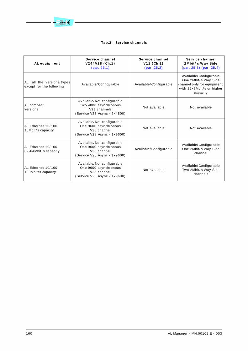
160 AL Manager - MN.00108.E - 003
Tab.2 - Service channels
AL equipmentService channelV24/V28 (Ch.1)
(par. 25.1)
Service channelV11 (Ch.2)(par. 25.2)
Service channel2Mbit/s Way Side
(par. 25.3) (par. 25.4)
AL, all the versions/typesexcept for the following
Available/Configurable Available/Configurable
Available/ConfigurableOne 2Mbit/s Way Side
channel only for equipment with 16x2Mbit/s or higher
capacity
AL compactversione
Available/Not configurableTwo 4800 asynchronous
V28 channels(Service V28 Async - 2x4800)
Not available Not available
AL Ethernet 10/10010Mbit/s capacity
Available/Not configurableOne 9600 asynchronous
V28 channel(Service V28 Async - 1x9600)
Not available Not available
AL Ethernet 10/10032-64Mbit/s capacity
Available/Not configurableOne 9600 asynchronous
V28 channel(Service V28 Async - 1x9600)
Available/ConfigurableAvailable/ConfigurableOne 2Mbit/s Way Side
channel
AL Ethernet 10/100100Mbit/s capacity
Available/Not configurableOne 9600 asynchronous
V28 channel(Service V28 Async - 1x9600)
Not availableAvailable/ConfigurableTwo 2Mbit/s Way Side
channels
AL Manager - MN.00108.E - 003 161
Section 5.APPENDIX
26 AVAILABILITY OF THE COMMANDS/PUSH-BUT-TONS
The availability of the menus, commands and push–buttons, present into the Radio PDH-AL: Equipmentwindow, is affected by the following factors:
- Status of the equipment connection to the supervisory system 78: Connected (Con), Discon-nected 79 (Discon), Unreachable (Unreac).
The connection status is pointed out into the equipment info area of the Radio PDH-AL: Equip-ment window (par. 3.6).
- Connection status of the LCT program (par. 28), to the equipment 78: Not connected (Not Con),Connected in Configuration modality (Config), Connected in Monitoring modality (Monitor).
The connection status of the LCT is pointed out into the status bar of the Radio PDH-AL: Equip-ment window (par. 3.4).
- Profile of the NMS5UX/NMS5LX user that has opened the Radio PDH-AL: Equipment window:Entry (E), Normal (N), Advanced (A), Privileged (P), Superuser (S).
Warning. If the choice of the menu, of the command or of the push–button opens a window where thereare some parameters, the system specifies also the operation type that can be executed.
The Get label points out that it is possible to check the parameters; the Get/Set one, that it is possible tocheck the parameters and also to set or to change them. When nothing is pointed out, this means that itis possible to execute both Get and Set operations.
Tab.3 points out the menus/commands, the push-buttons and the context where they can be used.
78 Factor meaningful only for the real NEs.
79 Warning. The disconnected status does not refer to the equipment status after the creation of the rel-evant NE object, but to the status taken after a disconnection command. In fact, it is possible to open theRadio PDH-AL Equipment window of an equipment only if it has been connected at least one time.

162 AL Manager - MN.00108.E - 003
Tab.3 - Availability of the menu/commands/push-buttons
Menu – Command, Button Equipment state a LCT presence a User profile
File - Close Con, Discon, Unreac Not Con, Config, Monitor E N A P S
File - Exit Con, Discon, Unreac Not Con, Config, Monitor E N A P S
Commands -Reset Equipment Controller
Con, Discon, Unreac Not Con, Config, Monitor N A P S
Commands - Alarm Re–Alignment Con Not Con, Monitor E N A P S
Commands - Line Test Con, Discon, Unreac Not Con, Config, Monitor E N A P S
Commands -View/Modify P.M. Status
ConGet – ConfigGet/Set – Not Con, Monitor
N A P S
Commands -Configuration Download
Con, Discon, Unreac Not Con, Config, Monitor N A P S
Commands - NE Sw/Fw Release Con, Discon b, Unreac b Not Con, Config b, Monitor N A P S
Commands - Modify LCT Configu-ration Mode – Enable/Disable
Con Not Con, Monitor N A P S
Alarms - Current Alarms Con, Unreac Not Con, Config, Monitor E N A P S
Alarms - Alarm History Con, Discon, Unreac Not Con, Config, MonitorGet – E NGet/Set c – A P S
Alarms - Equipment Severity Code Con Not Con, Monitor N A P S
Options -View Active Manual Operation
ConGet – ConfigGet/Set – Not Con, Monitor
Get – EGet/Set – N A P S
Options - LCT Logged Users Con Not Con, Config, MonitorGet – EGet/Set – N A P S
Options - LCT Equipment Users ConGet – ConfigGet/Set – Not Con, Monitor
P S
Options -View Acknowledge Status
Con, Unreac Not Con, Config, Monitor E N A P S
Maintenance -Radio Branch... Loop
Con, Discon d, Unreac dGet – ConfigGet/Set – Not Con, Monitor
Get – EGet/Set – N A P S
Maintenance - Radio Switch Con, Discon d, Unreac dGet – ConfigGet/Set – Not Con, Monitor
Get – EGet/Set – N A P S
PRBS… Con, Discon d, Unreac dGet – ConfigGet/Set – Not Con, Monitor
Get – EGet/Set – N A P S
User Input Con, Discon d, Unreac dGet – ConfigGet/Set – Not Con, Monitor
Get – EGet/Set – N A P S
User Output Con, Discon d, Unreac dGet – ConfigGet/Set – Not Con, Monitor
Get – EGet/Set – N A P S
Radio Equipment Con, Discon d, Unreac dGet – ConfigGet/Set – Not Con, Monitor
Get – EGet/Set – N A P S
Performance Monitoring Con, Discon d, Unreac dGet – ConfigGet/Set – Not Con, Monitor
Get – EGet/Set – N A P S
Eq. EAST Con, Discon d, Unreac dGet – ConfigGet/Set – Not Con, Monitor
Get – EGet/Set – N A P S
Eq. WEST Con, Discon d, Unreac dGet – ConfigGet/Set – Not Con, Monitor
Get – EGet/Set – N A P S
Base Band Con, Discon d, Unreac dGet – ConfigGet/Set – Not Con, Monitor
Get – EGet/Set – N A P S
Cross Connect Matrix Con, Discon d, Unreac dGet – ConfigGet/Set – Not Con, Monitor
Get – EGet/Set – N A P S
Eq Controller Con, Discon d, Unreac dGet – ConfigGet/Set – Not Con, Monitor
Get – EGet/Set – N A P S

AL Manager - MN.00108.E - 003 163
RIM… Con, Discon d, Unreac dGet – ConfigGet/Set – Not Con, Monitor
Get – EGet/Set – N A P S
RT… Con, Discon d, Unreac dGet – ConfigGet/Set – Not Con, Monitor
Get – EGet/Set – N A P S
Service... Con, Discon d, Unreac dGet – ConfigGet/Set – Not Con, Monitor
Get – EGet/Set – N A P S
a Factor meaningful only for the real NEs.
b Warning. In this condition, it is possible to program only the updating of the equipment sw/fw. Moredetailed information are reported into the NMS5UX/NMS5LX user manual.
c Deleting of the records into the Alarm History Browser window.
d When the equipment is in disconnected or unreachable status, the system points out the last con-figuration get by the equipment. In these statuses, the system does not allow executing get and/or setoperations.
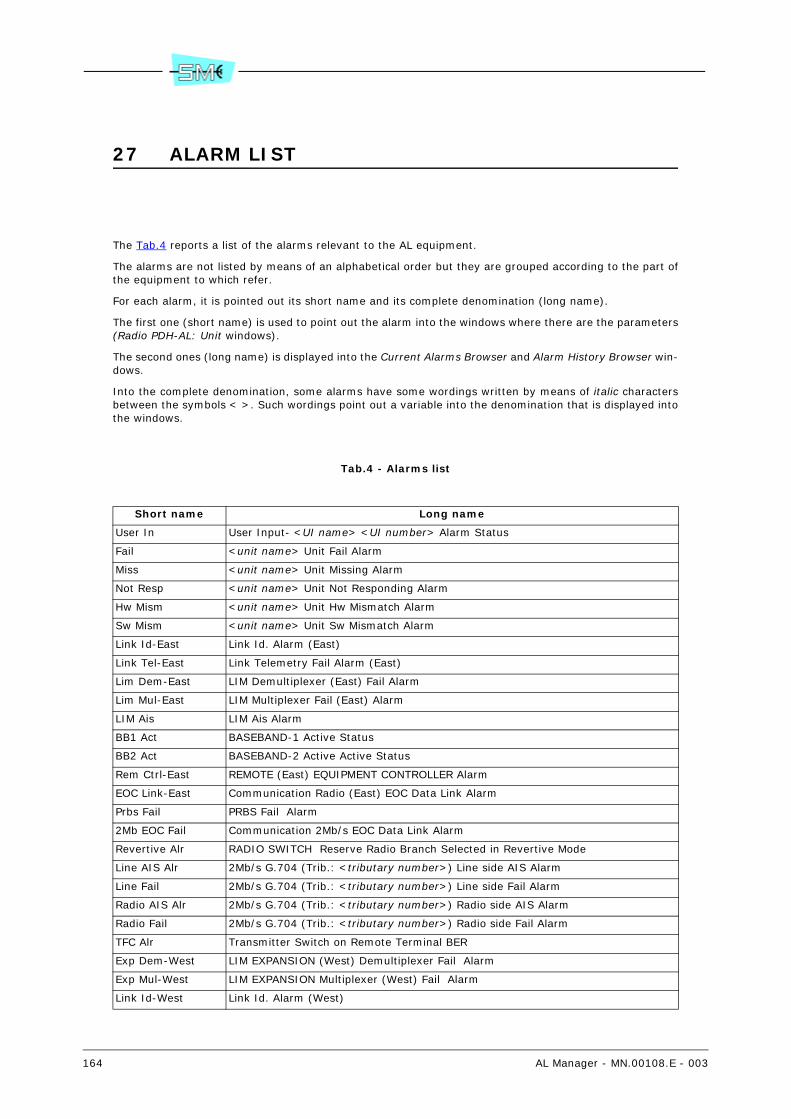
164 AL Manager - MN.00108.E - 003
27 ALARM LIST
The Tab.4 reports a list of the alarms relevant to the AL equipment.
The alarms are not listed by means of an alphabetical order but they are grouped according to the part ofthe equipment to which refer.
For each alarm, it is pointed out its short name and its complete denomination (long name).
The first one (short name) is used to point out the alarm into the windows where there are the parameters(Radio PDH-AL: Unit windows).
The second ones (long name) is displayed into the Current Alarms Browser and Alarm History Browser win-dows.
Into the complete denomination, some alarms have some wordings written by means of italic charactersbetween the symbols < >. Such wordings point out a variable into the denomination that is displayed intothe windows.
Tab.4 - Alarms list
Short name Long name
User In User Input- <UI name> <UI number> Alarm Status
Fail <unit name> Unit Fail Alarm
Miss <unit name> Unit Missing Alarm
Not Resp <unit name> Unit Not Responding Alarm
Hw Mism <unit name> Unit Hw Mismatch Alarm
Sw Mism <unit name> Unit Sw Mismatch Alarm
Link Id-East Link Id. Alarm (East)
Link Tel-East Link Telemetry Fail Alarm (East)
Lim Dem-East LIM Demultiplexer (East) Fail Alarm
Lim Mul-East LIM Multiplexer Fail (East) Alarm
LIM Ais LIM Ais Alarm
BB1 Act BASEBAND-1 Active Status
BB2 Act BASEBAND-2 Active Active Status
Rem Ctrl-East REMOTE (East) EQUIPMENT CONTROLLER Alarm
EOC Link-East Communication Radio (East) EOC Data Link Alarm
Prbs Fail PRBS Fail Alarm
2Mb EOC Fail Communication 2Mb/s EOC Data Link Alarm
Revertive Alr RADIO SWITCH Reserve Radio Branch Selected in Revertive Mode
Line AIS Alr 2Mb/s G.704 (Trib.: <tributary number>) Line side AIS Alarm
Line Fail 2Mb/s G.704 (Trib.: <tributary number>) Line side Fail Alarm
Radio AIS Alr 2Mb/s G.704 (Trib.: <tributary number>) Radio side AIS Alarm
Radio Fail 2Mb/s G.704 (Trib.: <tributary number>) Radio side Fail Alarm
TFC Alr Transmitter Switch on Remote Terminal BER
Exp Dem-West LIM EXPANSION (West) Demultiplexer Fail Alarm
Exp Mul-West LIM EXPANSION Multiplexer (West) Fail Alarm
Link Id-West Link Id. Alarm (West)

AL Manager - MN.00108.E - 003 165
Link Tel-West Link Telemetry Fail Alarm (West)
Rem Ctrl-West REMOTE EQUIPMENT CONTROLLER WEST Alarm
EOC Fail-West Communication Radio (West) EOC Data Link Alarm
Los LIM Tributary-<tributary number> Signal loss Alarm
Ais E1 MATRIX Tributary-<tributary number> Ais Alarm
Ber E1 MATRIX Tributary-<tributary number> Ber6 Alarm
OOF E1 MATRIX Tributary-<tributary number> Out of Frame Alarm
OOMF E1 MATRIX Tributary-<tributary number> Out of Multiframe Alarm
Rim Psu BRANCH-<a> RIM Power Supply Alarm
Rt Psu BRANCH-<a> RT Transceiver Power Supply Alarm
Rx Pwr L BRANCH-<a> RT Rx Power Low Alarm
Tx Pwr L BRANCH-<a> RT Tx Power Low Alarm
Mod Fail LIM BRANCH-<a> Modulator Fail Alarm
Dem Fail LIM BRANCH-<a> Demodulator Fail Alarm
Low BER LIM BRANCH-<a> Base Band LBER Alarm
High BER LIM BRANCH-<a> Base Band HBER Alarm
Cab Op BRANCH-<a> IDU-ODU Cable Open Alarm
Cab Sh BRANCH-<a> IDU-ODU Cable Short Alarm
BB Rx LIM BRANCH-<a> Base Band Rx Alarm
I-O Comm BRANCH-<a> RT IDU-ODU Communication fail Alarm
Ewl LIM BRANCH-<a> Base Band Ewl Alarm
Rt Vco BRANCH-<a> RT Rt Vco Fail Alarm
Rt If BRANCH-<a> RT Rt If Fail Alarm
Rx Act BRANCH-<a> Rx Active Status
Tx Act BRANCH-<a> Tx Active Status
Prx BRANCH-<a> Prx change
Ptx BRANCH-<a> Ptx change
I-O Comm LIM BRANCH-<a> ODU-IDU Communication fail Alarm
15M ES P.M. G.828-<b> 15Mcounter ES threshold cross Alarm
15M SES P.M. G.828-<b> 15Mcounter SES threshold cross Alarm
24H ES P.M. G.828-<b> 24Hcounter ES threshold cross Alarm
24H SES P.M. G.828-<b> 24Hcounter SES threshold cross Alarm
UAS P.M. G.828-<b> UAS Alarm
15M SEP P.M. G.828-<b> 15Mcounter SEP threshold cross Alarm
24H SEP P.M. G.828-<b> 24Hcounter SEP threshold cross Alarm
15M Rlts1 P.M. RT-<a> RxPower 15Mcounter Rlts1 threshold cross Alarm
15M Rlts2 P.M. RT-<a> RxPower 15Mcounter Rlts2 threshold cross Alarm
15M Rlts3 P.M. RT-<a> RxPower 15Mcounter Rlts3 threshold cross Alarm
15M Rlts4 P.M. RT-<a> RxPower 15Mcounter Rlts4 threshold cross Alarm
24H Rlts1 P.M. RT-<a> RxPower 24Hcounter Rlts1 threshold cross Alarm
24H Rlts2 P.M. RT-<a> RxPower 24Hcounter Rlts2 threshold cross Alarm
24H Rlts3 P.M. RT-<a> RxPower 24Hcounter Rlts3 threshold cross Alarm
24H Rlts4 P.M. RT-<a> RxPower 24Hcounter Rlts4 threshold cross Alarm
15M Tlts1 P.M. RT-<a> TxPower 15Mcounter Tlts1 threshold cross Alarm
15M Tlts2 P.M. RT-<a> TxPower 15Mcounter Tlts2 threshold cross Alarm
15M Tlts3 P.M. RT-<a> TxPower 15Mcounter Tlts3 threshold cross Alarm
15M Tlts4 P.M. RT-<a> TxPower 15Mcounter Tlts4 threshold cross Alarm
24H Tlts1 P.M. RT-<a> TxPower 24Hcounter Tlts1 threshold cross Alarm

166 AL Manager - MN.00108.E - 003
24H Tlts2 P.M. RT-<a> TxPower 24Hcounter Tlts2 threshold cross Alarm
24H Tlts3 P.M. RT-<a> TxPower 24Hcounter Tlts3 threshold cross Alarm
24H Tlts4 P.M. RT-<a> TxPower 24Hcounter Tlts4 threshold cross Alarm
Los BASE BAND Port Service <service channel type> Loss of Signal Alarm
Int Los BASE BAND Port Service <service channel type> Loss of Internal Signal Alarm
E1 Stat BASE BAND E1-<unit name> Aggregate-<c> Protection Alarm
LOS Lan LIM <LIM number> Signal loss Alarm
a 1, 2, East, West.
b Radio 1, Radio 2, Radio (switched), Tributary line side, Tributary radio side, Tributary line side Exp,Tributary radio side Exp, Radio East, Radio West.
c East, West

AL Manager - MN.00108.E - 003 167
28 LOCAL MANAGEMENT PROGRAM (LCT)
The supervisory and the management of the AL equipment can be remotely executed by means of theNMS5UX or NMS5LX system and also locally by means of a program, directly installed on the PC, calledLCT (Local Craft Terminal) 80.
The operation that can be executed, by means of the LCT program, are mainly the ones that can be exe-cuted with the NMS5UX or NMS5LX system.
Warning. More detailed information concerning the use of the LCT program are reported into the relevantuser manual/help on-line. Here below, there are only some indications concerning the relations betweenthe LCT program and the NMS5UX or NMS5LX system.
28.1 TYPES OF LCT–EQUIPMENT CONNECTION (Monitoring, Config-uration)
The local user can activate the connection between the LCT program and the equipment in two differentmodes: Monitoring or Configuration.
In Monitoring mode, it is possible to check the configuration and the equipment parameters, but it is notpossible to execute any changes or to request for the execution of an operation.
On the contrary, in Configuration mode, it is possible to check and to change the configuration and theparameters of the connected equipment.
The local activation of the LCT–equipment connection, in Monitoring mode, does not affect the acquisitionof the alarms or the forwarding of the commands executed by the system: the NMS5UX/NMS5LX user canopen the Radio PDH-AL: Equipment window and, he can also as check the configuration of the equipment(get operations) as change parameters and forward commands (set operations).
On the contrary, when the operator activates locally the LCT–equipment connection in Configuration mode,the NMS5UX/NMS5LX user can open the Radio PDH-AL: Equipment window, check the equipment config-uration (get operations) but he can not change the parameters or forward commands (set operations) withthe exception of the ones listed here below:
- To execute the software reset of the equipment (par. 9.1).
- To forward the Line Test command (par. 9.3).
- To transfer the equipment configuration (stored into the database of the supervisory system) toanother equipment (real or virtual one) of the same type (par. 9.5).
- To program the updating of the equipment software/firmware (par. 9.6).
- To force the disconnection (logout) of an user (par. 11.2).
During the period when it has been activated the connection in Configuration mode, it is not signalled tohe supervisory system any changes relevant to the alarms.
When the local connection between the LCT and the equipment has been deactivated, the NMS5UX orNMS5LX system automatically executes a reset procedure of the configuration (forwarding of the Config-uration Upload command) to take into account the possible changes executed by the local user and toget all the current alarm signals.
80 LCT is an additional software module of the SCT (Subnetwork Craft Terminal) or LMT (Link ManagerTerminal). Each Siae equipment is provided with its own additional software module. For the AL equipment,the additional software module is called LCT PDH-AL. More detailed information concerning the SCT/LCTprogram are reported into the SCT/LMT and LCT PDH-AL user manuals/help on-line.
168 AL Manager - MN.00108.E - 003
Warning. This operation involves the automatic closing and opening of the Radio PDH-AL: Equipment win-dow.
As in Monitoring mode as in Configuration one, the equipment spontaneously communicates, to theNMS5UX or NMS5LX system, the activation and the deactivation of the local connection, and it signals themto the user into the Radio PDH-AL: Equipment window 81 (refer to Fig.1).
81 The activation/deactivation of the LCT program is pointed out also on the NMS5UX/NMS5LX graphicalinterface at general level. For more detailed information refer to the NMS5UX or NMS5LX user manual.
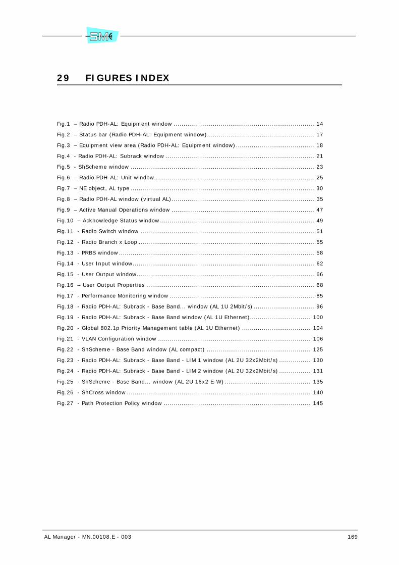
AL Manager - MN.00108.E - 003 169
29 FIGURES INDEX
Fig.1 – Radio PDH-AL: Equipment window ........................................................................ 14
Fig.2 – Status bar (Radio PDH-AL: Equipment window)....................................................... 17
Fig.3 – Equipment view area (Radio PDH-AL: Equipment window)........................................ 18
Fig.4 - Radio PDH-AL: Subrack window ............................................................................ 21
Fig.5 - ShScheme window .............................................................................................. 23
Fig.6 – Radio PDH-AL: Unit window.................................................................................. 25
Fig.7 – NE object, AL type .............................................................................................. 30
Fig.8 – Radio PDH-AL window (virtual AL)......................................................................... 35
Fig.9 – Active Manual Operations window ......................................................................... 47
Fig.10 – Acknowledge Status window............................................................................... 49
Fig.11 - Radio Switch window ......................................................................................... 51
Fig.12 - Radio Branch x Loop .......................................................................................... 55
Fig.13 - PRBS window.................................................................................................... 58
Fig.14 - User Input window............................................................................................. 62
Fig.15 - User Output window........................................................................................... 66
Fig.16 – User Output Properties ...................................................................................... 68
Fig.17 - Performance Monitoring window .......................................................................... 85
Fig.18 - Radio PDH-AL: Subrack - Base Band... window (AL 1U 2Mbit/s) ............................... 96
Fig.19 - Radio PDH-AL: Subrack - Base Band window (AL 1U Ethernet)............................... 100
Fig.20 - Global 802.1p Priority Management table (AL 1U Ethernet) ................................... 104
Fig.21 - VLAN Configuration window .............................................................................. 106
Fig.22 - ShScheme - Base Band window (AL compact) ..................................................... 125
Fig.23 - Radio PDH-AL: Subrack - Base Band - LIM 1 window (AL 2U 32x2Mbit/s) ................ 130
Fig.24 - Radio PDH-AL: Subrack - Base Band - LIM 2 window (AL 2U 32x2Mbit/s) ................ 131
Fig.25 - ShScheme - Base Band... window (AL 2U 16x2 E-W)............................................ 135
Fig.26 - ShCross window .............................................................................................. 140
Fig.27 - Path Protection Policy window ........................................................................... 145

170 AL Manager - MN.00108.E - 003
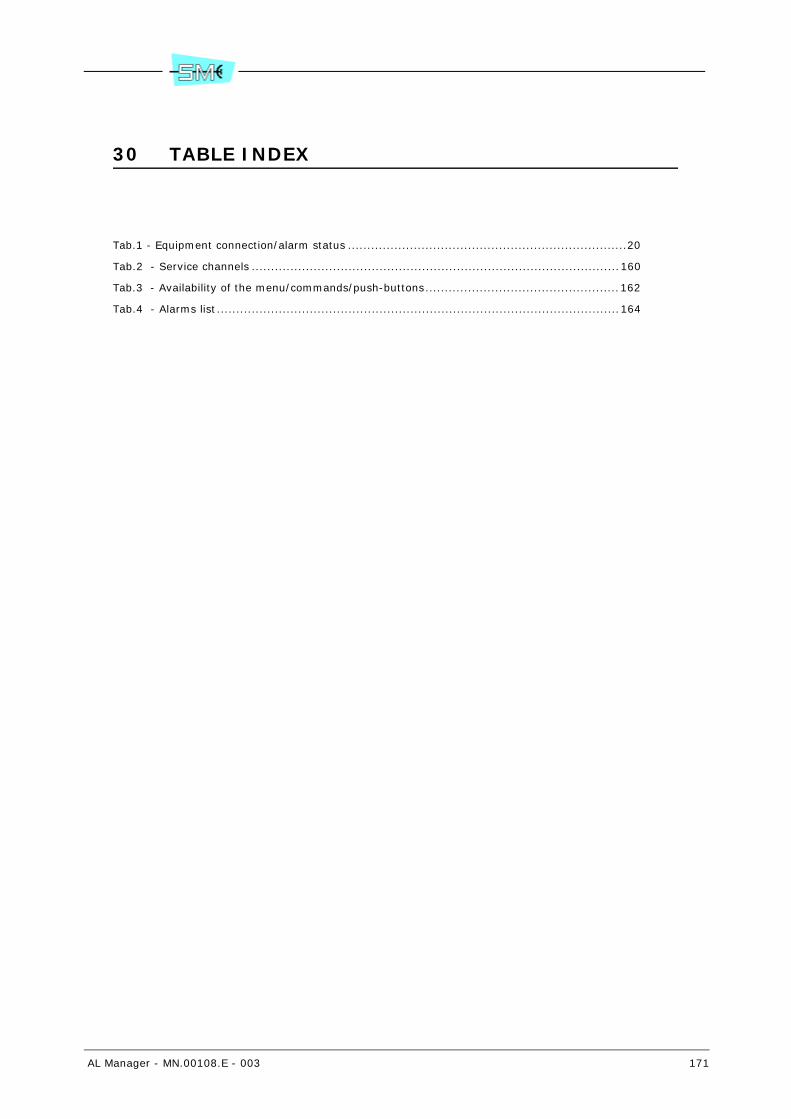
AL Manager - MN.00108.E - 003 171
30 TABLE INDEX
Tab.1 - Equipment connection/alarm status ........................................................................20
Tab.2 - Service channels ...............................................................................................160
Tab.3 - Availability of the menu/commands/push-buttons..................................................162
Tab.4 - Alarms list........................................................................................................164

172 AL Manager - MN.00108.E - 003

AL Manager - MN.00108.E - 003 173
31 OPERATIONS INDEX
Numerics
16Kbit used for the connection to the remote terminal ........................................................81
A
Acknowledge status of the alarms, LCT presence and Configuration Upload failed ....................48Activate, at the same time, one or more PM measurements .................................................41Activate/deactivate the PM measurements .........................................................................86Activate/reset the PRBS measure .....................................................................................59Activated condition of the local user input ..........................................................................63Add a new LCT user into the list .......................................................................................48Aggregate-aggregate connection (pass through) ...............................................................142Aging time of the MAC addresses stored in the specific table (AL 1U Ethernet) ......................103Alarms of LIM... block (AL 1U 2Mbit/s) ..............................................................................97Alarms of LIM... block (AL 1U Ethernet) ...........................................................................101Alarms of LIM... block (AL 2U 16x2 E-W) .........................................................................136Alarms of LIM... block (AL 2U 32x2Mbit/s) .......................................................................132Alarms of LIM... block (AL compact) ................................................................................126Alarms of RIM... block ...................................................................................................149Auto negotiation procedure for the external port (LAN 1, 2, 3) (AL 1U Ethernet) ...................112
B
Base band type of the local equipment ..............................................................................73Behaviour of the external port (LAN 1, 2, 3) towards the packets in output without Tag(AL 1U Ethernet) ..........................................................................................................113Behaviour of the internal port (Internal port) towards the packets in output without Tag(AL 1U Ethernet) ..........................................................................................................118Block diagram of the equipment ..............................................................................149, 151Block diagram of the equipment (AL 1U Ethernet) .............................................................100
C
Capacity of the local and remote equipment .......................................................................74Capacity of the local equipment ........................................................................................73Capacity of the specific branch - local and remote equipment (16x2 E-W) ..............................91Capacity of the specific branch - local equipment (16x2 E-W) ...............................................90Change the characteristics of the LCT users present into the list ...........................................48Characteristics of the 2Mbit/s Way Side service channel ....................................................158Characteristics of the 2Mbit/s Way Side service channel (AL Ethernet - 100Mbit/s) ................159Characteristics of V11 service channel (Ch2) ....................................................................157Characteristics of V24/V28 service channel (Ch1) .............................................................157Check the reach ability of the equipment ...........................................................................40Configuration of the virtual LANs (AL 1U Ethernet) ............................................................105Configuration parameters of the controller unit .................................................................148Configuration parameters of the IDU unit (AL compact) .....................................................126Configuration parameters of the LIM unit (AL 1U 2Mbit/s) ....................................................97

174 AL Manager - MN.00108.E - 003
Configuration parameters of the LIM unit (AL 1U Ethernet) ................................................101Configuration parameters of the LIM unit (AL 2U 16x2 E-W) ...............................................136Configuration parameters of the LIM unit (AL 2U 32x2Mbit/s) .............................................132Configuration parameters of the radio units .....................................................................155Configuration parameters of the RIM unit ........................................................................149Configuration parameters of the tributary fluxes (AL 1U Ethernet) ......................................123Connection identificative number of the local and remote equipment .....................................76Connection identificative number of the local equipment ......................................................75Connection identificative number of the specific branch - local and remote equipment(16x2 E-W) ...................................................................................................................92Connection identificative number of the specific branch - local equipment (16x2 E-W) .............92Control of Tag Vlan Id on the messages in input from the external port (LAN 1, 2, 3)(AL 1U Ethernet) ..........................................................................................................113Control of Tag Vlan Id on the messages in input from the internal port (Internal port)(AL 1U Ethernet) ..........................................................................................................117Copy, into a text editor, the signals list (Alarm History) .......................................................44Counters of the packets/bytes in input/output from the Ethernet ports (AL 1U Ethernet) ........121Couple with the user output a signal (alarms or UI) ............................................................67Create a virtual Lan (AL 1U Ethernet) ..............................................................................107
D
Data transmission speed of the external port (LAN 1, 2, 3) (AL 1U Ethernet) ........................111Deactivate the PRBS measure ..........................................................................................59Deactivate, at the same time, one or more PM measurements ..............................................41Default Vid value of the external port (LAN 1, 2, 3) (AL 1U Ethernet) ..................................112Default Vid value of the internal port (Internal port) (AL 1U Ethernet) .................................117Delete a connection ......................................................................................................143Delete a virtual Lan (AL 1U Ethernet) ..............................................................................108Delete/mark the signals (Alarm History) ............................................................................44Disable the alarms (Equipment Severity Code) ...................................................................44Disable the LCT user to be able to connect himself to the equipment by means of theLCT program, in Configuration mode .................................................................................42Disable the re-closure of an E1 on itself (loop) .................................................................143Disable the traps forwarding (Equipment Severity Code) ......................................................44
E
Emptying algorithm of the messages present in the output queue (AL 1U Ethernet) ..............103Enable the alarms and the traps forwarding (Equipment Severity Code) .................................44Enable the LCT user to be able to connect himself to the equipment by means of theLCT program, in Configuration mode .................................................................................42Enable the re-closure of an E1 on itself (loop) ..................................................................143Enable/disable the UI (local/remote) alarm or the forwarding of the trap to the supervisorysystem .........................................................................................................................63Enabled the forced activation of the relays contacts from operator ........................................69Enabling of the squelch on the services .............................................................................80Enabling of the switch in transmission ...............................................................................82Enabling status of the auto negotiation and, if the auto negotiation is inactive, the operationmodality and the transmission speed used by the external port (LAN 1, 2, 3)(AL 1U Ethernet) ..........................................................................................................110Enabling status of the external port (LAN 1, 2, 3) (AL 1U Ethernet) .....................................109Enabling status of the flow control of the external port (LAN 1, 2, 3) (AL 1U Ethernet) ...........111Enabling status of the internal port (Internal port) (AL 1U Ethernet) ....................................117Enabling status of the Link Loss Forwarding modality of the external port (LAN 1, 2, 3)(AL 1U Ethernet) ..........................................................................................................109Equipment cross connections .........................................................................................139
AL Manager - MN.00108.E - 003 175
EWL alarm threshold .......................................................................................................77EWL alarm threshold (16x2 E-W) ......................................................................................94
F
Filter the list of the alarm signals (Equipment Severity Code) ...............................................45Filter the signals list (Alarm History) .................................................................................44Filter the signals list (Current Alarms) ...............................................................................43Force the activation of the relay contacts relevant to a user output .......................................69Force the disconnection (logout) of a user .........................................................................47Force the download of the default name of the user output ..................................................70Force the equipment to forward its current alarms ..............................................................40Force the switch on the preferential branch without waiting for the Wait Time ........................53Freeze the window (Current Alarms) .................................................................................43Functioning mode of the user output relay contacts ............................................................67Functioning status of the ATPC .......................................................................................154
G
General parameters of the Ethernet Lan interface (AL 1U Ethernet) .....................................102
H
HBER alarm threshold .....................................................................................................77HBER alarm threshold (16x2 E-W) ....................................................................................93History of the signals (Alarm History) ................................................................................44
I
Insertion of the AIS signal at the receive side .....................................................................79Intervention threshold (High/Low) of the ATPC device .......................................................155Inversion status of the Tx and Rx lines of the external port (LAN 1, 2, 3) (AL 1U Ethernet) ....109
L
LBER alarm threshold .....................................................................................................76LBER alarm threshold (16x2 E-W) ....................................................................................93LCT user list of the NE ....................................................................................................48List of the alarm signals (Equipment Severity Code) ............................................................44List of the PM measurements ...........................................................................................40List of the signals (Current Alarms) ...................................................................................43List of the users connected with the equipment ..................................................................47Local seriousness level coupled with the alarm signal (Equipment Severity Code) ....................44
M
Management of the preferential branch in reception (Rx Preferential) ....................................52Management of the preferential branch in transmission (Tx Preferential) ................................53Management of the switching in reception (Rx Forced Switch) ..............................................50Management of the switching in transmission (Tx Forced Switch) ..........................................52Manual operations actually activated .................................................................................46Manual operations timeout ..............................................................................................47Mark the signals (Current Alarms) ....................................................................................43Maximum number of MAC Addresses managed per port (AL 1U Ethernet) ............................102

176 AL Manager - MN.00108.E - 003
Maximum output power value at the transmitter ...............................................................154Maximum size of the accepted packet (AL 1U Ethernet) .....................................................105Mode used for the management of the "preferential connection" .........................................147Mode used for the switching management (automatic or forced) .........................................146Modulation of the local and remote equipment ...................................................................75Modulation of the local equipment ....................................................................................74Modulation of the specific branch - local and remote equipment (16x2 E-W) ...........................91Modulation of the specific branch - local equipment (16x2 E-W) ............................................91Modulation status of the RF carrier .................................................................................153
N
Name of the tributary (AL compact) ................................................................................129Name of the user input (local/remote) ..............................................................................62Name of the user output .................................................................................................66Not protected tributary-aggregate connection ..................................................................141Number of the timeslot used for the connection to the remote terminal .................................81
O
Open the Equipment Info… window of the NE (Alarm History) ...............................................44Open the Equipment Info… window of the NE (Current Alarms) .............................................43Operation of the RT power supply ...................................................................................153Operation of the transmitter ..........................................................................................152
P
Parameters of the Ethernet Lan external port LAN-1, LAN-2 e LAN-3 (AL 1U Ethernet) ...........108Parameters of the Ethernet Lan Internal Port 1 (radio aggregate connection)(AL 1U Ethernet) ..........................................................................................................116Point out the NE symbol into the map window (Alarm History) ..............................................44Point out the NE symbol into the map window (Current Alarms) ............................................43Ports through which the messages in input from the external port (LAN 1, 2, 3) transit(AL 1U Ethernet) ..........................................................................................................114Ports through which the messages in input from the internal port (Internal port) transit(AL 1U Ethernet) ..........................................................................................................119PRBS measure status ......................................................................................................57Priority criterion used to associate the packets in input from the external port (LAN 1, 2, 3)to the output queue (AL 1U Ethernet) .............................................................................114Priority criterion used to associate the packets in input from the internal port (Internal port)to the output queue (AL 1U Ethernet) .............................................................................119Protected tributary-aggregate connection ........................................................................142Protection type of the local equipment ..............................................................................73
R
Remove a LCT user from the list .......................................................................................48Remove the force activation of the relay contacts relevant to a user output ............................70Reset of the alarms concerning the threshold exceeding (PM) ...............................................89Reset the counters’ results (internal/external port) (AL 1U Etherent) ...................................122Reset the equipment .......................................................................................................39Reset the Transmitter Switch on Remote Rx Alarm that notifies the switch in transmission .......83Reset the values concerning the control parameters (PM) ....................................................89Resolution of the received power (Prx) ..............................................................................82Resolution of the transmitted power (Ptx) ..........................................................................82
RF channel of the local and remote equipment .................................................................152

AL Manager - MN.00108.E - 003 177
RF channel of the local equipment ..................................................................................151
S
Save/print the signals list (Alarm History) ..........................................................................44Save/print the signals list (Current Alarms) ........................................................................43Seriousness level of an UI (local/remote) ..........................................................................63Signal used for the PRBS measure ....................................................................................60Status of a protected connection (main and standby) ........................................................144Status of loops ...............................................................................................................54Status of the PM measurements and the relevant alarms concerning the threshold exceeding ...84Status of the tributaries use (AL 1U Ethernet) ..................................................................123Status of the tributary line side loops (AL Ethernet) ...................................................123, 124Switch the functioning of the memory benches of the main controller ....................................41
T
T and N parameters ........................................................................................................83Threshold of the signal at reception, under which the related alarms are activated ..................76Threshold of the signal at reception, under which the related alarms are activated (16x2 E-W) .93Thresholds of the control parameters and intervention ones of the alarms (PM) ......................87Thresholds of the Rx and Tx power level (PM) ....................................................................88Time between two different signals (Alarm History) .............................................................44Time between two different signals (Current Alarms) ..........................................................43Time interval (hysteresis) after which the Link Loss Forwarding modality is activated(AL 1U Ethernet) ..........................................................................................................105Transfer the configuration of the equipment under examination to one or more real NEs ..........41Transfer the configuration of the equipment under examination to one or more virtual NEs ......41Transmission modality of the external port (LAN 1, 2, 3) (AL 1U Ethernet) ...........................112Tributaries use (AL 1U 2Mbit/s) ........................................................................................98Tributaries use (AL 2U 16x2 E-W) ...................................................................................137Tributaries use (AL 2U 32x2Mbit/s) .................................................................................133Tributaries use (AL compact) .........................................................................................127Tributary internal side loops (AL 1U 2Mbit/s) ......................................................................99Tributary internal side loops (AL 2U 16x2 E-W) ................................................................138Tributary internal side loops (AL 2U 32x2Mbit/s) ...............................................................134Tributary internal side loops (AL compact) .......................................................................128Tributary line side loops (AL 1U 2Mbit/s) ...........................................................................98Tributary line side loops (AL 2U 16x2 E-W) ......................................................................137Tributary line side loops (AL 2U 32x2Mbit/s) ....................................................................133Tributary line side loops (AL compact) .............................................................................128Tributary status (AL 1U 2Mbit/s) ......................................................................................95Tributary status (AL 2U 16x2 E-W) .................................................................................135Tributary status (AL 2U 32x2Mbit/s) ...............................................................................129Tributary status (AL compact) ........................................................................................125Tributary used for the connection to the remote terminal/tributary used for the PM measures ...80Type of interface of the "remote" port for the connection to the remote terminals ...................80Type of PRBS pattern used for the measure .......................................................................59
U
Update the equipment software/firmware ..........................................................................41User input status (local/remote) .......................................................................................61User output status ..........................................................................................................65Using of the EWL alarm as switching criterion .....................................................................78Using of the HBER alarm as switching and AIS insertion criterion at reception .........................77
178 AL Manager - MN.00108.E - 003
Using of the LBER alarm as switching criterion ...................................................................78Using of the number of errors detected by FEC as switching criterion in reception ...................79
V
Value to insert in the 802.1p field of the packets in input without Tag 802.1p, but in outputwith Tag for the external port (LAN 1, 2, 3) (AL 1U Ethernet) .............................................115Value to insert in the 802.1p field of the packets in input without Tag 802.1p, but in outputwith Tag for the internal port (Internal port) (AL 1U Ethernet) ............................................120Verify the counters of the packets/bytes in input/output from the Ethernet (internal/external)port (AL 1U Etherent) ...................................................................................................121Verify the existing virtual LANs (AL 1U Ethernet) ..............................................................106Verify/modify which output queue a packet in input from the external port (LAN 1, 2, 3)must be associated to, according to its Tag 802.1p (level 2) (AL 1U Ethernet) ......................115Verify/modify which output queue a packet in input from the internal port (Internal port)must be associated to, according to its Tag 802.1p (level 2) (AL 1U Ethernet) ......................120Verify/modify which output queue a packet, in input to any Ethernet port, must be assigned,depending on its Tag 802.1p (AL 1U Ethernet) .................................................................103Version of the equipment software/firmware ......................................................................41
W
Wait Time parameter (Radio Switch) .................................................................................53

AL Manager - MN.00108.I - 003 179
32 PARAMETERS INDEX
Numerics
15 Min ES Threshold .................................. 87
15 Min Rlts1 (Rlts2, Rlts3, Rlts4) Threshold .. 88
15 Min SEP Threshold ................................ 87
15 Min SES Threshold ................................ 87
15 Min Tlts1 (Tlts2, Tlts3, Tlts4) Threshold ... 88
16kb/s Ch in 64Kbit TS for PPP .................... 81
24 Hour ES Threshold ................................ 87
24 Hour Rlts1 (Rlts2, Rlts3, Rlts4) Threshold . 88
24 Hour SEP Threshold .............................. 88
24 Hour SES Threshold .............................. 88
24 Hour Tlts1 (Tlts2, Tlts3, Tlts4) Threshold .. 88
2Mb Tributary for EOC/PM .......................... 80
802.1Q VLan Default Vid (Internal port) ......117
802.1Q VLan Default Vid (LAN 1, 2, 3) ........112
802.1Q VLan Ingress Filtering Check(Internal port) .........................................118
802.1Q VLan Ingress Filtering Check(LAN 1, 2, 3) ...........................................113
A
Active State (UI) ....................................... 63
Active State (UO) ...................................... 67
After Switch - G828 Counters ...................... 85
Ais Rx Insertion ........................................ 79
Alarm Configuration(2Mbit/s Way Side service) ........................158
Alarm Configuration (Tributary...)(2Mbit/s Way Side service) ........................159
Atpc Threshold on local Prx - High ..............155
Atpc Threshold on local Prx - Low ...............155
B
Base Band Configuration ............................ 73
BBE (Background Block Errors) ................... 86
C
Cable crossover (LAN 1, 2, 3) ....................110
Carrier Only .............................................154
Checked Signal ......................................... 60
Configuration ............................................ 73
D
Def. VID (VLAN) .......................................106
Default Priority Queue (Internal port) ..........120
Default Priority Queue (LAN 1, 2, 3) ............115
Duplex Status (LAN 1, 2, 3) .......................112
E
Early Warning -> Rx Sw ............................. 78
Early Warning Threshold ............................ 77
Early Warning Threshold (32x2 E-W) ........... 94
Egress ....................................................103
Egress Default Priority (Internal port) ..........120
Egress Default Priority (LAN 1, 2, 3) ...........116
Egress Mode (Internal port) .......................118
Egress Mode (LAN 1, 2, 3) .........................113
Egress Priority Policy .................................103
Enable (AL 1U 2Mbit/s) .............................. 98
Enable (AL 1U Ethernet) ............................123
Enable (AL 2U 16x2 E-W) ..........................137
Enable (AL 2U 32x2Mbit/s) ........................133
Enable (AL compact) .................................127
ES (Errored Second) .................................. 86
Expected Type (AL 1U 2Mbit/s) ................... 97
Expected Type (AL 1U Ethernet) .................101
Expected Type (AL 2U 16x2 E-W) ...............136
Expected Type (AL 2U 32x2Mbit/s) .............132
Expected Type (AL compact) ......................127
Expected Type (Eq. Controller) ...................148
Expected Type (RIM) ................................150
Expected Type (RT) ..................................155
F
FEC CRC Errors -> Rx Sw ........................... 79
Flow Control (LAN 1, 2, 3) .........................111
Forced Operator Status (UO) ....................... 70
Forced Switch (Cross Connect) ...................146
G
Global 802.1p Priority Management ............104
180 AL Manager - MN.00108.I - 003
H
Hardware Edition (AL 1U 2Mbit/s) ................ 97
Hardware Edition (AL 1U Ethernet) .............101
Hardware Edition (AL 2U 16x2 E-W) ...........136
Hardware Edition (AL 2U 32x2Mbit/s) ..........132
Hardware Edition (AL compact) ..................127
Hardware Edition (Eq. Controller) ...............148
Hardware Edition (RIM) .............................150
Hardware Edition (RT) ...............................156
Hber -> Rx Ais Rx Sw ................................ 78
HBer Threshold ......................................... 77
HBer Threshold (32x2 E-W) ........................ 93
I
Interface Priority (Internal port) .................119
Interface Priority (LAN 1, 2, 3) ...................115
Internal Loop (2Mbit/s Way Side service) .....158
Internal Loop (AL 1U 2Mbit/s) ..................... 99
Internal Loop (AL 1U Ethernet) ..................124
Internal Loop (AL 2U 16x2 E-W) .................138
Internal Loop (AL 2U 32x2Mbit/s) ...............134
Internal Loop (AL compact) .......................128
Internal Loop (Tributary...)(2Mbit/s Way Side service) ........................159
Internal Status (UO) ............................. 67, 69
L
Label (AL 1U 2Mbit/s) ................................ 97
Label (AL 1U Ethernet) ..............................101
Label (AL 2U 16x2 E-W) ............................136
Label (AL 2U 32x2Mbit/s) ..........................132
Label (AL compact) ........................... 127, 129
Label (Eq. Controller) ................................148
Label (RIM) .............................................150
Label (RT) ...............................................156
Label (UI) ................................................ 62
Label (UO) ............................................... 66
Label (VLAN) ...........................................106
Lan 1 (VLAN) ...........................................106
Lan 2 (VLAN) ...........................................107
Lan 3 (VLAN) ...........................................107
Lan Statistics ...........................................121
LBer -> Rx Sw .......................................... 78
LBer Threshold .......................................... 76
LBer Threshold (32x2 E-W) ......................... 93
Line Loop (2Mbit/s Way Side service) ..........158
Line Loop (AL 1U 2Mbit/s) .......................... 98
Line Loop (AL 1U Ethernet) ........................124
Line Loop (AL 2U 16x2 E-W) ......................137
Line Loop (AL 2U 32x2Mbit/s) ....................133
Line Loop (AL compact) .............................128
Line Loop (Tributary...)(2Mbit/s Way Side service) ........................159
Link Capacity ............................................ 74
Link Capacity (32x2 E-W) ........................... 91
Link Channel Number cursor (Low) .............152
Link ID ..................................................... 76
Link ID (32x2 E-W) .................................... 92
Link Modulation Type ................................. 75
Link Modulation Type (32x2 E-W) ................ 91
LLF (LAN 1, 2, 3) ......................................109
LLF Wait Time ..........................................105
Local Capacity (Local NE) ........................... 73
Local Capacity (Local NE) (32x2 E-W) .......... 90
Local Channel Number cursor (Low) ............152
Local Link ID (Local NE) ............................. 75
Local Link ID (Local NE) (32x2 E-W) ............ 92
Local Modulation Tyepe .............................. 74
Local Modulation Type (32x2 E-W) ............... 91
Loop Enable .............................................. 54
M
MAC Addr. Aging Time ..............................103
Max Num. Of MAC Addr. ............................102
Max Packet Size .......................................105
Max Ptx Value ..........................................155
N
Num. SES to reset UAS .............................. 87
Num. SES to set UAS ................................. 87
P
Parent Part Number (AL 1U 2Mbit/s) ............ 98
Parent Part Number (AL 1U Ethernet) ..........101
Parent Part Number (AL 2U 16x2 E-W) ........136
Parent Part Number (AL 2U 32x2Mbit/s) ......132
Parent Part Number (AL compact) ..............127
Parent Part Number (Eq. Controller) ............148
Parent Part Number (RIM) .........................150
Parent Part Number (RT) ...........................156
Part Number (AL 1U 2Mbit/s) ...................... 97
Part Number (AL 1U Ethernet) ...................101
Part Number (AL 2U 16x2 E-W) ..................136
Part Number (AL 2U 32x2Mbit/s) ................132
Part Number (AL compact) ........................127
Part Number (Eq. Controller) .....................148
Part Number (RIM) ...................................150
Part Number (RT) .....................................156
Percent. BBE to set SES ............................. 87
AL Manager - MN.00108.I - 003 181
Port (Internal port) ...................................117
Port (LAN 1, 2, 3) .....................................109
Port 1 (VLAN) ..........................................107
PRBS Start ............................................... 57
Preferential Switch (Cross Connect) ............147
Preferential WTR (0-180 sec) ...................... 53
Prx Measurement Resolution ....................... 82
Ptx Control ..............................................154
Ptx Measurement Resolution ....................... 82
R
Radio Branch x - G828 Counters .................. 85
Radio Branch x - Rx Pwr Counters ............... 85
Radio Branch x - Tx Pwr Counters ................ 85
Received Power Level Threshold 1(2, 3, 4) ................................................... 88
Remote Access Type .................................. 80
RLTM (Received Level Tide Mark) ................ 86
RLTS (Received Level Threshold Second) ...... 86
Rt PSU ....................................................153
Rx Forced Switch ....................................... 50
Rx Preferential .......................................... 52
Rx Signal Level Alarm Thresh ...................... 76
Rx Signal Level Alarm Thresh (32x2 E-W) ..... 93
S
SEP (Severely Errored Period) ..................... 86
Serial Number (AL 1U 2Mbit/s) .................... 98
Serial Number (AL 1U Ethernet) .................101
Serial Number (AL 2U 16x2 E-W) ...............136
Serial Number (AL 2U 32x2Mbit/s) ..............132
Serial Number (AL compact) ......................127
Serial Number (Eq. Controller) ...................148
Serial Number (RIM) .................................150
Serial Number (RT) ..................................156
Service Squelch ........................................ 80
SES (Severely Errored Seconds) .................. 86
Severity Code (UI) .................................... 63
Side Id (2Mbit/s Way Side service) .............158
Side Id (Ch1 service) ................................157
Side Id (Ch2 service) ................................158
Speed Duplex (LAN 1, 2, 3) .......................110
Speed status (LAN 1, 2, 3) ........................111
Start Stop (PM) ......................................... 87
Switch Status (Cross Connect) ...................144
T
Test Pattern ............................................. 59
Time slot for EOC ...................................... 81
TLTM (Transmitted Level Tide Mark) ............ 86
TLTS (Transmitted Level Threshold Second) .. 86
Tributary N... - Line Side G828 Counters ...... 85
Tributary N... - Radio Side G828 Counters .... 85
Tx Forced Switch ....................................... 52
Tx Power Lever Threshold 1 (2, 3, 4) ........... 88
Tx Preferential .......................................... 53
Tx Switch on rem Alr - Alr Threshold ............ 83
Tx Switch on rem Alr - Check Period ............ 83
Tx Switch on remote Alr ............................. 83
Tx Transmitter .........................................152
Type (2Mbit/s Way Side service) ........ 158, 159
Type (Ch1 service) ...................................157
Type (Ch2 service) ...................................158
U
UAS (UnAvailable Seconds) ......................... 86
V
VLan ID (VLAN) ........................................106
VLan Port (Internal port) ...........................119
VLan Port (LAN 1, 2, 3) .............................114

182 AL Manager - MN.00108.I - 003

AL Manager - MN.00108.E - 003 183
33 ASSISTANCE SERVICE
The assistance service provided by Siae Microelettronica will be in compliance, if stipulated, to what spe-cified in the Agreement of Software Maintenance.
To exploit this service, fill in all its parts the Module for the notification of bad SW operation(RQ.00961) and send it to the following address:
SIAE Microelettronica S.p.Avia Michelangelo Buonarroti, 2120093 Cologno MonzeseMilano - Italywww.siaemic.it
Fax + (39) 02 25391585e-mail [email protected]
33.1 RQ.00961 MODULE
Each RQ916 module can contain at most one signalling.
The information required for the signalling of the bad operation.
Warning. The compiling of the parts General Information (Siae only), Trouble notified by, Reserved to SiaeDepartment and Validation manager are at charge of the Siae personnel.
Section – Trouble Identification
- SIAE product name. Identifier or SIAE code of the product whose bad operation has been detected.
- Version. Version of the sw product whose bad operation has been detected
- Documentation Type. Identifier of the document where the problem has been detected.
- Revision. Revision of the document where the problem has been detected.
- Volume N. Number of the volume of the document where the problem has been detected.
- Page N. Number of the page, into the volume, where the problem has been detected.
- Typology. Severity of the detected bad operation:
- Critical, if it prevents the use of a main functionality of the product;
- Important, if it prevents the use of a secondary functionality of the product;
- Disturbing, if occasionally and in difficultly reproducible conditions, it prevents the use of a mainfunctionality of the product;
- Minor, if very seldom it prevents the use of a secondary functionality without important conse-quences;
- Suggestion, if no functionality of the product is damaged but some aspects (e.g.: user interface)can be improved.
- Recurrent. Possibility (Yes) or not (No) to cause the bad operation after the same sequence of inputsgiven to the product.
- Repeatable. Possibility (Yes) or not (No) to reproduce the detected bad operation.
- Annexes. Possibility (Yes) or not (No) of annexed to the NM and their possible number.

184 AL Manager - MN.00108.E - 003
- Title. Title of the bad operation.
- Description. Clear and concise description of the bad operation, comprehensive of the edge condi-tions and, when possible and applicable, of the reference to the test (identifier and version of thetechnical documentation, test identifier).
GENERAL INFORMATION (SIAE ONLY)
Object Software Documentation Hardware Number
Submitted Distribution List: Quality Assurance
TROUBLE NOTIFIED BY
Siae Operator Name _______________________________ Date _______________________________
Customer Report Ref. _______________________________ Date _______________________________
Customer Name Reference _______________________________ Tel _______________________________
Company/Dept. _______________________________ e-mail _______________________________
Contract N Address
TROUBLE IDENTIFICATION
SW/FW failures
SIAE product name ___________________________________________________ Version ______
Documentation
Documentation type ___________________________________________________ Revision ______
Volume N. ___________________________________________________
Page N.
Typology Critical Important Disturbing Minor Suggestion
Recurrent Yes No
Repeatable Yes No
Annexes Yes: N° No
Title:Description (including enviranmental conditions):
RESERVED TO SIAE DEPARTMENT
Trouble Accepted_Open
Rejected Reasons
Notes
Analysis performed by Date Expected Closing Date
CORRECTIVE ACTION DESCRIPTION
FIXED Executed by Date Approved by
VALIDATION MANAGER
MN Closed Open
Verified by Date
Notes
Quality Record Module TROUBLE REPORT Issued byTerzo L.
Approved byGaviraghi S.
Date24/09/02
Page1/1
Siae Microelettronica all rights reserved.
Document Ref.RQ.00961
Rev/Ver003


