Proving Ground Report No. 405160-14-1 Report Date: May 2009 ALTERNATIVE DESIGN OF GUARDRAIL POSTS IN ASPHALT OR CONCRETE MOWING PADS by Dusty R. Arrington Engineering Research Associate Roger P. Bligh, P.E. Research Engineer and Wanda L. Menges Research Specialist Contract No.: T4541 Task AL Test No.: 405160-14-B1-B5 Test Date: 2008-07-14&15 Sponsored by Roadside Safety Research Program Pooled Fund Study No. TPF-5(114) TEXAS TRANSPORTATION INSTITUTE PROVING GROUND Mailing Address: Located at: Roadside Safety & Physical Security Texas A&M Riverside Campus Texas A&M University System Building 7091 3135 TAMU 3100 State Highway 47 ISO 17025 Laboratory Testing Certificate # 2821.01 College Station, TX 77843-3135 Bryan, TX 77807
Transcript
Proving Ground
Report No. 405160-14-1 Report Date: May 2009 ALTERNATIVE DESIGN OF GUARDRAIL POSTS IN ASPHALT OR CONCRETE MOWING PADS by Dusty R. Arrington Engineering Research Associate Roger P. Bligh, P.E. Research Engineer and Wanda L. Menges Research Specialist Contract No.: T4541 Task AL Test No.: 405160-14-B1-B5 Test Date: 2008-07-14&15 Sponsored by Roadside Safety Research Program Pooled Fund Study No. TPF-5(114)
TEXAS TRANSPORTATION INSTITUTE PROVING GROUND Mailing Address: Located at: Roadside Safety & Physical Security Texas A&M Riverside Campus Texas A&M University System Building 7091 3135 TAMU 3100 State Highway 47
ISO 17025 LaboratoryTesting Certificate # 2821.01 College Station, TX 77843-3135 Bryan, TX 77807
DISCLAIMER The contents of this report reflect the views of the authors who are solely responsible for the facts and accuracy of the data, and the opinions, findings and conclusions presented herein. The contents do not necessarily reflect the official views or policies of the Washington Department of Transportation, The Texas A&M University System, or Texas Transportation Institute. This report does not constitute a standard, specification, or regulation. In addition, the above listed agencies assume no liability for its contents or use thereof. The names of specific products or manufacturers listed herein does not imply endorsement of those products or manufacturers. The results reported herein apply only to the article being tested.
_______________________________________ Wanda L. Menges, Research Specialist Deputy Quality Manager
________________________________________ Richard A. Zimmer, Senior Research Specialist Test Facility Manager Quality Manager Technical Manager
Technical Report Documentation Page 1. Report No.
2. Government Accession No.
3. Recipient's Catalog No.
4. Title and Subtitle ALTERNATIVE DESIGN OF GUARDRAIL POSTS IN
SPHALT OR CONCRETE MOWING PADS A
5. Report Date May 2009 6. Performing Organization Code
7. Author(s) Dusty R. Arrington, Roger P. Bligh, and Wanda L. Menges
8. Performing Organization Report No. 405160-14-1
9. Performing Organization Name and Address Texas Transportation Institute Proving Ground The Texas A&M University System College Station, Texas 77843-3135
10. Work Unit No. (TRAIS) 11. Contract or Grant No. T4541 Task AL
1 2. Sponsoring Agency Name and Address
Washington State Department of Transportation Transportation Building, MS 47372 O lympia, Washington 98504-7372
13. Type of Report and Period Covered Test Report March 2008 – May 2009 14. Sponsoring Agency Code
15. Supplementary Notes Research Study Title: Task Order #AL – Alternate Design for Installation of Guardrail Posts in Asphalt or Concrete Name of Contacting Representative: Dave Olson 16. Abstract The objective of this project was to identify alternative backfill materials for the low strength two-sack grout mix currently used to fill the voids around posts in guardrail mow strips. In order to maintain impact performance, a candidate material should have a compressive strength comparable to the grout that was successfully crash tested in a mow strip application. The material should be able to retard vegetation growth around the guardrail posts without restricting its motion in an impact event. Static laboratory and dynamic bogie impact testing was conducted to evaluate several products for use around guardrail posts encased in a pavement mow strip. A two-sack grout mixture that had been successfully crash tested under a previous research study was used as a baseline reference for acceptable impact performance. The basis of the evaluation was that if a candidate product offered resistance to post movement in the leave out section that was equal to or less than that of the two-sack grout, it could be considered an acceptable alternative without the need for further crash testing. The products that were investigated include a two-part urethane foam, a molded rubber product that has an insert fabricated to match the size of the leaveout, a flat recycled rubber mat that rests on top of a leave out backfilled with soil, and a new pop-out concrete wedge conceived under this project. 17. Key Words Mow strip, longitudinal barrier, vegetation control, oadside safety r
18. Distribution Statement Copyrighted. Not to be copied or reprinted without consent from Washington DOT.
19. Security Classif.(of this report) Unclassified
20. Security Classif.(of this page) Unclassified
21. No. of Pages 60
22. Price
Form DOT F 1700.7 (8-72) Reproduction of completed page authorized
ACKNOWLEDGMENTS
This research project was performed under a pooled fund program between the State of Alaska Department of Transportation and Public Facilities, California Department of Transportation (Caltrans), Louisiana Department of Transportation and Development, Minnesota Department of Transportation, Tennessee Department of Transportation, Texas Department of Transportation and Washington State Department of Transportation, and the Federal Highway Administration. The authors acknowledge and appreciate their guidance and assistance.
Roadside Safety Research Pooled Fund Committee
CONTACTS Revised December 2008
ALASKA Jeff Jeffers Statewide Traffic & Safety Engineering Asst State of Alaska Department of Transportation and Public Facilities 3132 Channel Drive Juneau, AK 99801 (907) 465-8962 [email protected] Clint Adler, P.E. Research Engineer Alaska Department of Transportation and Public Facilities Research and Technology Transfer 2301 Peger Road Fairbanks, AK 99709 (907) 451-5321 [email protected] Kurt Smith, P.E. Statewide Traffic & Safety Engineer Alaska Department of Transportation & Public Facilities 3132 Channel Drive Juneau, AK 99801-7898 (907) 465-6963 [email protected]
CALIFORNIA John Jewell, P.E. Caltrans Office of Materials and Infrastructure Division of Research and Innovation 5900 Folsom Blvd Sacramento, CA 95819 (916) 227-5824 (916) 227-5856 [email protected] LOUISIANA Paul Fossier Bridge and Structural Design Section P.O. Box 94245 Baton Rouge, LA 79084-9245 (225)379-1323 [email protected] Harold “Skip” Paul Associate Director, Research Louisiana Transportation Center 4101 Gourrier Ave. Baton Rouge, LA 70808 (225) 767-9102 [email protected]
MINNESOTA Michael Elle, P.E. Design Standards Engineer Minnesota Department of Transportation 395 John Ireland Blvd, MS 696 St. Paul, MN 55155 (651) 296-4859 [email protected] James Klessig, Pooled Fund Manager Minnesota Department of Transportation Office of Investment Management Research Services Section 395 John Ireland Blvd, MS 330 St. Paul, MN 55155 [email protected] TENNESSEE Ali Hangul Director, Design Division Tennessee Department of Transportation Suite 1300 James K. Polk State Office Building Nashville, TN 37243-0348 (615) 741-0840 [email protected] TEXAS Mark A. Marek Design Division Texas Department of Transportation 125 East 11th Street Austin, TX 78701-2483 (512) 416-2653 [email protected] Charmaine Richardson [email protected]
WASHINGTON Dave Olson, Chair Design Policy, Standards, & Research Manager Washington State Department of Transportation (360) 705-7952 [email protected] Rhonda Brooks, Research Manager Washington State Department of Transportation P.O. Box 47372 Olympia, WA 98504-7372 (360) 705-7945 [email protected] FEDERAL HIGHWAY ADMINISTRATION Ken Opiela U.S. Department of Transportation Federal Highway Administration Turner-Fairbanks Highway Research Center Mail Code: HRDS-04 6300 Georgetown Pike McLean, VA 22101 (202) 493-3371 [email protected] TEXAS TRANSPORTATION INSTITUTE D. Lance Bullard, Jr., P.E. Research Engineer Roadside Safety & Physical Security Div. Texas Transportation Institute Texas A&M University System College Station, TX 77843-3135 (979) 845-6153 [email protected]
TEXAS TRANSPORTATION INSTITUTE (continued) C. Eugene Buth, Ph.D., P.E. Senior Research Fellow Roadside Safety & Physical Security Div. Texas Transportation Institute Texas A&M University System College Station, TX 77843-3135 (979) 845-6159 [email protected] Roger P. Bligh, Ph.D., P.E. Research Engineer Roadside Safety & Physical Security Div. Texas Transportation Institute Texas A&M University System College Station, TX 77843-3135 (979) 845-4377 [email protected]
4.1 TEST PLAN.................................................................................................................. 17 4.2 TEST ARTICLE DESIGN AND CONSTRUCTION .................................................. 17 4.3 TEST VEHICLE AND ACTUAL IMPACT CONDITIONS ...................................... 18 4.4 WEATHER CONDITIONS.......................................................................................... 19 4.5 TEST DESCRIPTION .................................................................................................. 19
4.5.1 Test B1 ...................................................................................................................... 19 4.5.2 Test B2 ...................................................................................................................... 20 4.5.3 Test B3 ...................................................................................................................... 21 4.5.4 Test B4 ...................................................................................................................... 23 4.5.5 Test B5 ...................................................................................................................... 24
5. DISCUSSION OF RESULTS FROM BOGIE VEHICLE IMPACT TESTING ................... 27
TABLE OF CONTENTS (CONTINUED) Section Page 6. SUMMARY AND RECOMMENDATIONS.......................................................................... 33
6.2 RECOMMENDATIONS .............................................................................................. 35 REFERENCES ............................................................................................................................. 37 APPENDIX A. TEST ARTICLE DETAILS ............................................................................. A-1 APPENDIX B. BOGIE NOSE DETAILS ................................................................................. B-1 APPENDIX C. BOGIE TEST PROCEDURES ........................................................................ C-1
C.1 ELECTRONIC INSTRUMENATION AND DATA PROCESSING ........................ C-1 C.2 PHOTOGRAPHIC INSTRUMENATION AND DATA PROCESSING .................. C-1
LIST OF FIGURES Page Figure 1: Current recommendations for installation of guardrail posts in mow strips. ................ 2 Figure 2: US Composites foam. .................................................................................................... 7 Figure 3: Rainbow Technologies foam. ........................................................................................ 7 Figure 4: Welch Products, Inc. – The TopHat™. ......................................................................... 8 Figure 5: Foam sample – noticeable large voids found at bottom of cylindrical samples. ......... 11 Figure 6: Rainbow Pole Setting Foam-Test Setup. ..................................................................... 12 Figure 7: Graph of static load test data (Rainbow Pole Setting Foam). ..................................... 12 Figure 8: US Composites-test setup. ........................................................................................... 13 Figure 9: Graph of static load test data (US Composites). ......................................................... 13 Figure 10: Test mold – overhead view ......................................................................................... 15 Figure 11: Test mold – side view ................................................................................................. 15 Figure 12: Test mold – perspective view ...................................................................................... 15 Figure 13: Form for foam forming test. ........................................................................................ 15 Figure 14: Installing top plates on mold after placement of foam mixture. ................................. 15 Figure 15: Foam overflow through vent holes. ............................................................................. 16 Figure 16: Finished product. ......................................................................................................... 16 Figure 17: Mow strip test setup for bogie impact tests. ................................................................ 18 Figure 18: Leaveout with two-sack grout prior to test B1. ........................................................... 19 Figure 19: Post in standard two-sack grout after test B1. ............................................................. 20 Figure 20: Post in two part urethane foam prior to test B2. .......................................................... 21 Figure 21: Post in two part urethane foam after test B2. .............................................................. 21 Figure 22: Post in full-strength unreinforced concrete wedge prior to test B3. ............................ 22 Figure 23: Post in full-strength unreinforced concrete wedge after test B3. ................................ 22 Figure 24: Post with TopHat™ recycled rubber mat prior to test B4. .......................................... 23 Figure 25: Post with TopHat™ recycled rubber mat after test B4. .............................................. 24 Figure 26: Post with flat mat prior to test B5. ............................................................................... 25 Figure 27: Post with flat mat after test B5. ................................................................................... 25 Figure 28: Acceleration-time histories from bogie impact tests (180 Hz filter). .......................... 28 Figure 29: Force-time histories from bogie impact tests. ............................................................. 29 Figure 30: 10 msec average acceleration-time histories from bogie impact test. ......................... 30 Figure 31: Energy time history. .................................................................................................... 31
LIST OF TABLES Page Table B1: Configuration of bogie nose and honeycomb. ........................................................... B-1
1. INTRODUCTION 1.1 PROBLEM The Louisiana DOTD has adopted new details for guardrail posts set in asphalt or concrete mowing strips. The details were adopted from a technical memorandum issued by the Federal Highway Administration (FHWA) in March 2004 (1) and research conducted by the Texas Transportation Institute (TTI) and documented in a January 2004 report entitled “Dynamic Response of Guardrail Systems encased in Pavement Mow Strips.” (2) Due to constructability issues associated with the leave-out sections required around the posts in the mow strip, construction costs have increased. Additionally, some guardrail installers have had problems producing the low-strength grout mix required as backfill in the upper portion of these leave-out sections. 1.2 BACKGROUND Unchecked, roadside vegetation growth can impede motorist vision at intersections and degrade the appearance of a roadside guardrail. In an effort to reduce maintenance costs and the safety risk to workers associated with hand mowing around guardrail, and amid recent environmental concerns regarding the use of herbicides to control roadside vegetation growth, there is a growing trend toward encasing guardrail posts in pavement mow strips. This pavement layer prevents vegetation growth in the vicinity of a guardrail installation and, thereby, reduces or eliminates the need for hand mowing or herbicides. However, if not properly designed, a mow strip can negatively influence the impact performance of a guardrail system. A strong-post guardrail system relies on the ability of the posts to rotate through the confining soil medium to help dissipate the energy of an impacting vehicle. The increased stiffness induced by the confinement of the pavement mow strip can lead to premature failure or fracture of a post. This post failure can lead to snagging or pocketing of a vehicle in the guardrail system and, ultimately, rupture or override of the w-beam rail element and/or overturn of the impacting vehicle. The mow strips may also influence safety by making the repair of guardrail installations more difficult and time consuming after they have been struck. The Texas Department of Transportation (TxDOT) sponsored research at the Texas Transportation Institute (TTI) to develop a crashworthy means of encasing guardrail in an asphalt or concrete mowing strip. The research approach consisted of dynamic bogie vehicle testing of steel and wood posts in various mow strip configurations, computer simulation, and full-scale crash testing. The research resulted in a design for guardrail in mow strip that meets the guidelines of National Cooperative Highway Research Program (NCHRP) Report 350. (3)
1
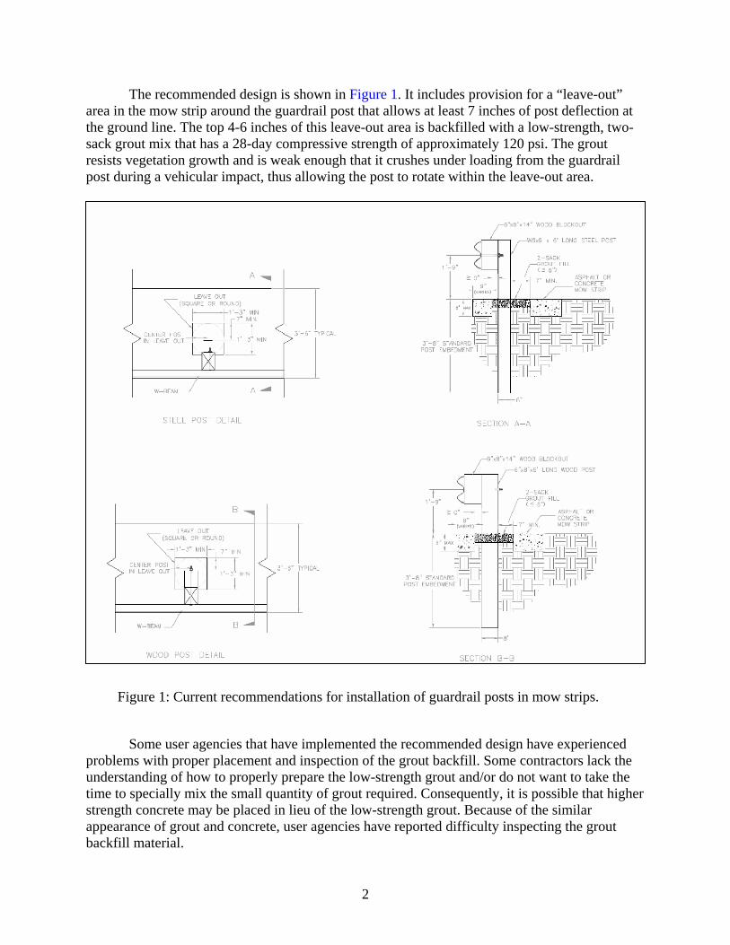
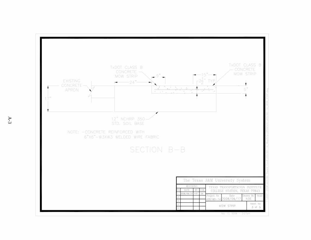
The recommended design is shown in Figure 1. It includes provision for a “leave-out” area in the mow strip around the guardrail post that allows at least 7 inches of post deflection at the ground line. The top 4-6 inches of this leave-out area is backfilled with a low-strength, two-sack grout mix that has a 28-day compressive strength of approximately 120 psi. The grout resists vegetation growth and is weak enough that it crushes under loading from the guardrail post during a vehicular impact, thus allowing the post to rotate within the leave-out area.
Figure 1: Current recommendations for installation of guardrail posts in mow strips.
Some user agencies that have implemented the recommended design have experienced problems with proper placement and inspection of the grout backfill. Some contractors lack the understanding of how to properly prepare the low-strength grout and/or do not want to take the time to specially mix the small quantity of grout required. Consequently, it is possible that higher strength concrete may be placed in lieu of the low-strength grout. Because of the similar appearance of grout and concrete, user agencies have reported difficulty inspecting the grout backfill material.
2
3
The researchers that developed the original guardrail-in-mow strip design indicated that any increase in post confinement beyond that provided by the two-sack grout backfill material should undergo additional analysis and full-scale testing. However, it was noted that other leave-out backfill materials (e.g. foams) may be acceptable as alternatives to the two-sack grout provided their compressive strength does not exceed that of the grout. It was further stated that the strength of an alternative leave-out backfill material can be demonstrated through laboratory and/or dynamic bogie vehicle testing. Alternative leave-out backfill materials should also have a demonstrated ability to resist vegetation growth. 1.3 OBJECTIVES The objective of this project was to identify alternative backfill materials for the low strength two-sack grout mix currently used to fill the voids around posts in guardrail mow strips. In order to maintain impact performance, a candidate material should have a compressive strength comparable to the grout that was successfully crash tested in a mow strip application. The material should be able to retard vegetation growth around the guardrail posts without restricting its motion in an impact event. 1.4 SCOPE OF RESEARCH The scope of the research included both static laboratory and dynamic impact testing of the identified candidate backfill materials. Depending on the nature of the material, selected products were subjected to laboratory testing to quantify their compressive strength. A computer-based data acquisition system will be used to record applied compressive load versus time. The results of these static laboratory tests were used as an initial screening to determine if the compressive strength of a candidate material was in a range that warranted further investigation through dynamic impact testing. Some candidate materials such as rubber matting did not lend themselves to compressive testing and, consequently, their evaluation was limited to dynamic impact testing.
Selected backfill materials that met the initial screening were further evaluated through
dynamic bogie vehicle impact testing. A representative concrete mow strip was constructed for use in the testing program. Guardrail posts were embedded to a standard depth in NCHRP Report 350 standard soil within leave-out sections cast into the mow strip. The new candidate backfill materials were used in the top portion of the leave-out section. The posts were impacted head-on by a bogie impact vehicle with a reusable, crushable nose assembly. The results of these tests were used to determine which candidate backfill materials can be recommended for use without comprising the impact performance of the guardrail system encased in the mow strip.
2. CANDIDATE PRODUCT IDENTIFICATION AND SELECTION 2.1 LITERATURE REVIEW A literature review was conducted as part of a product search for potential backfill materials suitable for use around guardrail posts. The products should have compressive strength of approximately 120 psi, resist vegetation growth, be formable or moldable to the dimensions of the leave out, and be environment friendly. Below is a list of products that were identified and considered. 2.1.1 Bio-Barrier Bio-Barrier is an herbicide impregnated membrane that is buried at varying depths and orientations depending on the effect that is desired. The use that most closely reflects the objective of the project is its use as a surface vegetation inhibitor. This material works by releasing an herbicidal gas into the soil just below the surface. This gas restricts root growth causing the eventual starvation of the plant. This product offers promise for vegetation control around guardrail installations in locations that do not restrict the use of herbicides. Additional information on the product can be found at the following website: http://www.biobarrier.com. An extensive study of this product entitled “Evaluations of Bio-Barrier in Specific Applications to Control Herbaceous Vegetation” is currently being conducted by researchers in the Environmental Management Program of the Texas Transportation Institute (TTI). 2.1.2 California Department of Transportation Caltrans has been researching for years how to provide a vegetation barrier that is both aesthetically pleasing and environmentally friendly. An article in the April 2006 issue of Better Roads entitled “Hardscaping with Caltrans: California tests new vegetation-control methods for those hard-to-manage areas along roadsides” by Kerry L. Clines summarizes Caltrans’ efforts to test and evaluate different products and methods for preventing vegetation growth below and around guardrails. Additional details can be found on the Caltrans website at: http://www.dot.ca.gov/hq/LandArch/roadside/. These vegetation control methods are all alternatives to using a pavement mow strip. 2.1.3 Preformed Polyurethane Foam Inserts (Clark Foam) TTI received samples of a preformed polyurethane foam product that is intended to be inserted into the leave outs around the guardrail posts in pavement mow strips. Note that the samples were received too late to be included in the laboratory or dynamic bogie testing. If the foam is formulated to have the proper compressive strength, the preformed insert would be viable from an impact performance standpoint.
However, there are some perceived disadvantages regarding the use of a preformed insert. First, adequate quality control and dimensional tolerances would need to be established for the leave out sections to avoid either the individual reshaping of the foam insert or large gaps between the surfaces of the leave out and foam insert that could permit the growth of vegetation over time. The depth of soil backfill below the foam insert would also have to be controlled to maintain the proper height of the foam insert relative to the surrounding pavement surface. If the surface of the foam insert drops below the surface of the pavement mow strip, the leave out could collect dirt and eventually permit the growth of undesired vegetation. Conversely, it might be aesthetically undesirable for the surface of the foam insert to extend too far above the surface of the pavement mow strip. The placement of the post within the leave out is likely to have more variation than the dimensions of the leave out itself. Whether installing the post by driving or drilling and backfilling, small longitudinal and lateral variations in placement relative to the leave out are to be expected. A preformed insert has the added complication of having to fit over or around the guardrail post in addition to fitting within the leave out. Finally, a strong adhesive would be needed to fill any small gaps between the foam insert, the leave out, and the post, and to provide the required adhesion to keep the insert in place and not float up during a rain. 2.1.4 Cellular Concrete (Cellular Concrete LLC) In recent years, researchers have worked to develop an ultra light low strength concrete for special applications such as roof decking and large foundations. One method involves introducing a large percentage of small air voids into concrete paste by injecting a low density foam into an application nozzle that mixes the concrete and foam before it is sprayed into a form. This process creates densities similar to that of regular top soil and compression strengths below that of the grout mixture currently used in mow strip applications. One of the problems with this process is that the specialty foam is hard to generate in small quantities. In consultation with Cellular Concrete LLC, it was suggested that small batches of foam could be generated using a standard battery powered drill with a special agitation bit. Due to the length of time required to develop a standard mixing procedure, it was not possible to test a cellular concrete product under this project. However, the product offers promise as a replacement for the standard grout mix. Some additional research is needed to evaluate the proposed foam agitation procedure for the small concrete batches required for use in the leave outs of pavement mow strips. 2.2 SELECTED PRODUCTS/METHODS Of the products identified and considered, there were only a few that had sufficient merit to warrant further evaluation and were mature enough to meet the timeline of the project. Presented below is a description of the products that were selected for testing and evaluation.
6
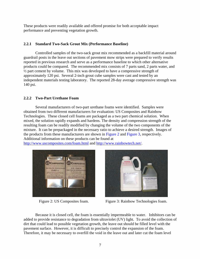
These products were readily available and offered promise for both acceptable impact performance and preventing vegetation growth. 2.2.1 Standard Two-Sack Grout Mix (Performance Baseline) Controlled samples of the two-sack grout mix recommended as a backfill material around guardrail posts in the leave out sections of pavement mow strips were prepared to verify results reported in previous research and serve as a performance baseline to which other alternative products could be compared. The recommended mix consists of 7 parts sand, 2 parts water, and ½ part cement by volume. This mix was developed to have a compressive strength of approximately 120 psi. Several 2-inch grout cube samples were cast and tested by an independent materials testing laboratory. The reported 28-day average compressive strength was 140 psi. 2.2.2 Two-Part Urethane Foam Several manufacturers of two-part urethane foams were identified. Samples were obtained from two different manufacturers for evaluation: US Composites and Rainbow Technologies. These closed cell foams are packaged as a two part chemical solution. When mixed, the solution rapidly expands and hardens. The density and compression strength of the resulting foam can be readily modified by changing the volume of the two components of the mixture. It can be prepackaged in the necessary ratio to achieve a desired strength. Images of the products from these manufacturers are shown in Figure 2 and Figure 3, respectively. Additional information on these products can be found at http://www.uscomposites.com/foam.html and http://www.rainbowtech.net/.
Figure 2: US Composites foam.
Figure 3: Rainbow Technologies foam.
Because it is closed cell, the foam is essentially impermeable to water. Inhibitors can be added to provide resistance to degradation from ultraviolet (UV) light. To avoid the collection of dirt that could lead to possible vegetation growth, the leave out should be filled level with the pavement surface. However, it is difficult to precisely control the expansion of the foam. Therefore, it may be necessary to overfill the void in the leave out and later cut the foam level
with the ground surface for aesthetic purposes, or use a temporary form across the top of the leave out to confine and produce more even expansion of the foam. If confined to a volume much less than the free-expansion volume, the foam could have greater than desired strength. 2.2.3 Rubber Inserts/Mats Two products manufactured from recycled crumb rubber were obtained from Welch Products, Inc. The TopHat™ (shown in Figure 4) is designed to be used as a permanent form around guardrail posts in concrete mow strips. It can reportedly be manufactured in a variety of shapes, colors and configurations. The lower portion of the TopHat™ matches the inside perimeter of the leave out and fits inside it. The area between the walls of the lower portion of the product is left as a void space. The upper portion consists of a 21-inch x 21-inch x 3/8-inch thick mat that extends over the edges of the leaveout to prevent vegetation growth. The mat has a cutout that matches the shape of the post. Because the TopHat™ is fabricated in one piece, it must be slid into position over the guardrail post, or the post must be driven after the TopHat™ is placed in the leaveout. A silicone sealant or other suitable adhesive is used to help seal the perimeter of the mat to the post and pavement mow strip.
(a) Top view.
(b) Insert view. (c) Side view.
Figure 4: Welch Products, Inc. – The TopHat™. The other product was a flat, recycled rubber mat that fits around the post and on top of the mow strip. The dimensions of the mat were 21-inch x 21-inch x 3/8-inch thick. The leaveout section is backfilled with soil to an elevation level with the surface of the pavement mow strip. The shape of the post can be cut into the mat. Scribe lines for typical post shapes can be incorporated into the mat to facilitate cutting. The mat must then be slid into position over the guardrail post, or the post must be driven after the mat is placed over the leaveout. A silicone sealant or other suitable adhesive is used to help seal the perimeter of the mat to the post and pavement mow strip. Both products are meant to provide physical barrier to vegetation growth around the post. Additional information on these products can be found at the manufacturer’s website: http://www.welchproducts.com/Welch_Products/Quality_Products/.
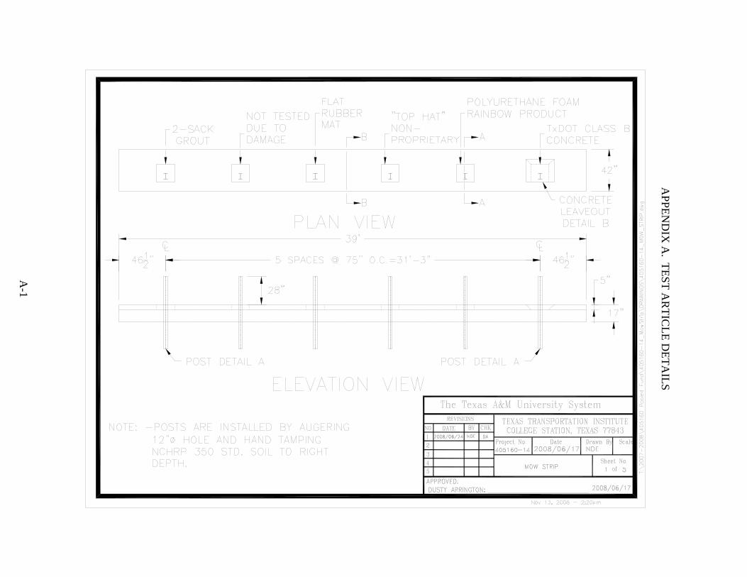
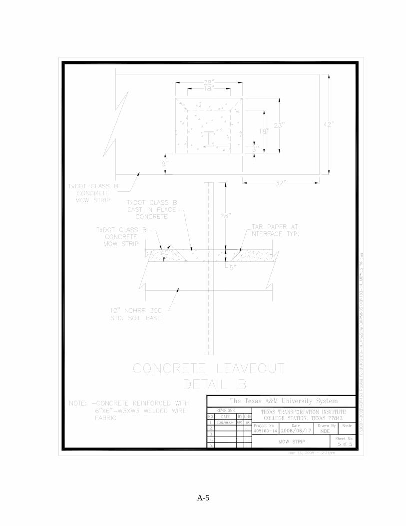
2.2.4 Pop-Out Concrete Wedge The obvious problem with using concrete in the leave out is that it severely restricts post movement at ground level in an impact event. The solution to this problem has been to provide a weaker material in a leaveout section around the post that can crush or fracture during an impact and subsequently permit free rotation of the post in the leaveout section. Another possible solution is to allow the material around the post to displace rather than crush. This would theoretically permit higher strength products such as conventional concrete to be used. Toward this goal, one of the potential solutions conceived by TTI researchers and investigated under this project involved using conventional concrete in a leaveout with modified geometry that provides an opportunity for the concrete to displace or “pop-out” of the leaveout during an impact. The two sides and rear edge of the leaveout are chamfered at a 45 deg angle to allow the backfill material to be pushed up and out of the leaveout upon loading from the post. This allows the post to rotate within the leaveout without having the strength limitations associated with crushing the backfill material. Note that a bond breaking material must be applied to all of the internal faces of the leaveout to permit the backfill material to readily release from the surrounding pavement mow strip. In the bogie test, roofing tar paper was used as a bond breaker and conventional concrete was used as the backfill material. Sheet 5 of 5 in Appendix A provides additional details of this concept.
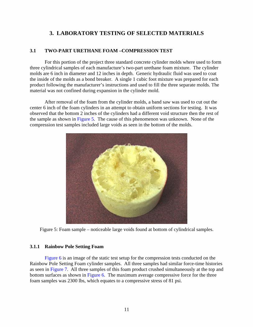
3. LABORATORY TESTING OF SELECTED MATERIALS 3.1 TWO-PART URETHANE FOAM –COMPRESSION TEST For this portion of the project three standard concrete cylinder molds where used to form three cylindrical samples of each manufacture’s two-part urethane foam mixture. The cylinder molds are 6 inch in diameter and 12 inches in depth. Generic hydraulic fluid was used to coat the inside of the molds as a bond breaker. A single 1 cubic foot mixture was prepared for each product following the manufacturer’s instructions and used to fill the three separate molds. The material was not confined during expansion in the cylinder mold. After removal of the foam from the cylinder molds, a band saw was used to cut out the center 6 inch of the foam cylinders in an attempt to obtain uniform sections for testing. It was observed that the bottom 2 inches of the cylinders had a different void structure then the rest of the sample as shown in Figure 5. The cause of this phenomenon was unknown. None of the compression test samples included large voids as seen in the bottom of the molds.
Figure 5: Foam sample – noticeable large voids found at bottom of cylindrical samples.
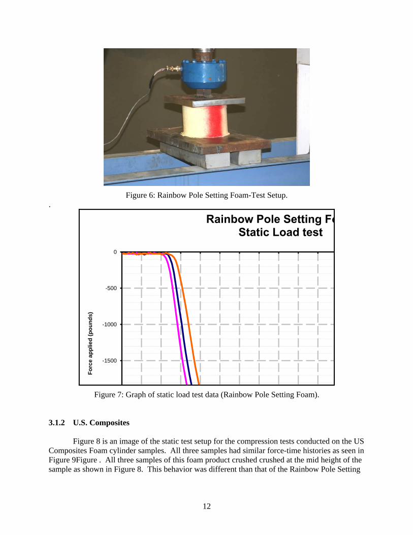
3.1.1 Rainbow Pole Setting Foam Figure 6 is an image of the static test setup for the compression tests conducted on the Rainbow Pole Setting Foam cylinder samples. All three samples had similar force-time histories as seen in Figure 7. All three samples of this foam product crushed simultaneously at the top and bottom surfaces as shown in Figure 6. The maximum average compressive force for the three foam samples was 2300 lbs, which equates to a compressive stress of 81 psi.
11
Figure 6: Rainbow Pole Setting Foam-Test Setup.
.
-1500
-1000
-500
0
Forc
e ap
plie
d (p
ound
s)
Figure 7: Graph of static load test data (Rainbow Pole Setting Foam).
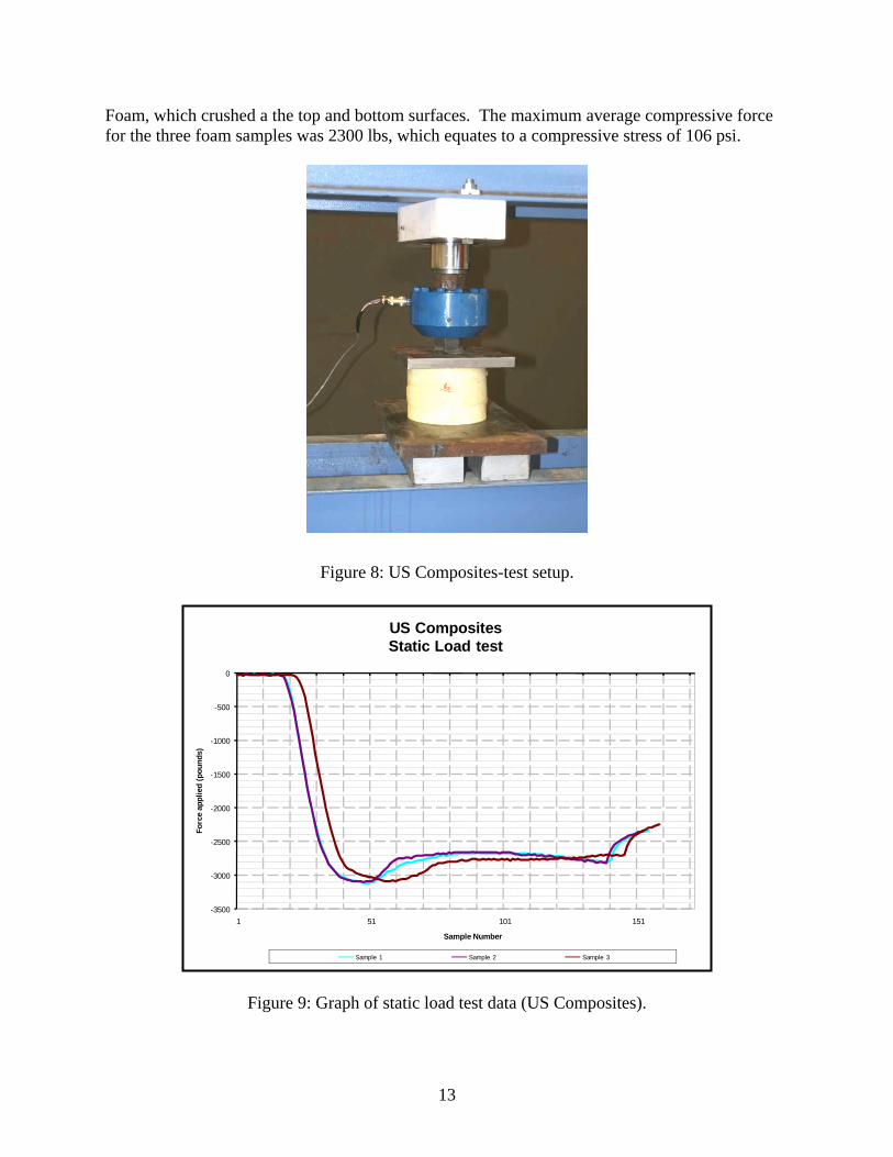
3.1.2 U.S. Composites Figure 8 is an image of the static test setup for the compression tests conducted on the US Composites Foam cylinder samples. All three samples had similar force-time histories as seen in Figure 9Figure . All three samples of this foam product crushed crushed at the mid height of the sample as shown in Figure 8. This behavior was different than that of the Rainbow Pole Setting
12
Foam, which crushed a the top and bottom surfaces. The maximum average compressive force for the three foam samples was 2300 lbs, which equates to a compressive stress of 106 psi.
Figure 8: US Composites-test setup.
-3500
-3000
-2500
-2000
-1500
-1000
-500
0
1 51 101 151
Forc
e ap
plie
d (p
ound
s)
Sample Number
US CompositesStatic Load test
Sample 1 Sample 2 Sample 3
Figure 9: Graph of static load test data (US Composites).
13
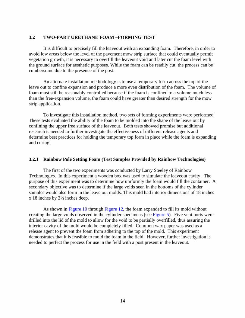
3.2 TWO-PART URETHANE FOAM –FORMING TEST It is difficult to precisely fill the leaveout with an expanding foam. Therefore, in order to avoid low areas below the level of the pavement mow strip surface that could eventually permit vegetation growth, it is necessary to overfill the leaveout void and later cut the foam level with the ground surface for aesthetic purposes. While the foam can be readily cut, the process can be cumbersome due to the presence of the post. An alternate installation methodology is to use a temporary form across the top of the leave out to confine expansion and produce a more even distribution of the foam. The volume of foam must still be reasonably controlled because if the foam is confined to a volume much less than the free-expansion volume, the foam could have greater than desired strength for the mow strip application. To investigate this installation method, two sets of forming experiments were performed. These tests evaluated the ability of the foam to be molded into the shape of the leave out by confining the upper free surface of the leaveout. Both tests showed promise but additional research is needed to further investigate the effectiveness of different release agents and determine best practices for holding the temporary top form in place while the foam is expanding and curing. 3.2.1 Rainbow Pole Setting Foam (Test Samples Provided by Rainbow Technologies) The first of the two experiments was conducted by Larry Steeley of Rainbow Technologies. In this experiment a wooden box was used to simulate the leaveout cavity. The purpose of this experiment was to determine how uniformly the foam would fill the container. A secondary objective was to determine if the large voids seen in the bottoms of the cylinder samples would also form in the leave out molds. This mold had interior dimensions of 18 inches x 18 inches by 2½ inches deep. As shown in Figure 10 through Figure 12, the foam expanded to fill its mold without creating the large voids observed in the cylinder specimens (see Figure 5). Five vent ports were drilled into the lid of the mold to allow for the void to be partially overfilled, thus assuring the interior cavity of the mold would be completely filled. Common wax paper was used as a release agent to prevent the foam from adhering to the top of the mold. This experiment demonstrates that it is feasible to mold the foam in the field. However, further investigation is needed to perfect the process for use in the field with a post present in the leaveout.
14
Figure 10: Test mold –
overhead view Figure 4: Test mold –
side view Figure 5: Test mold –
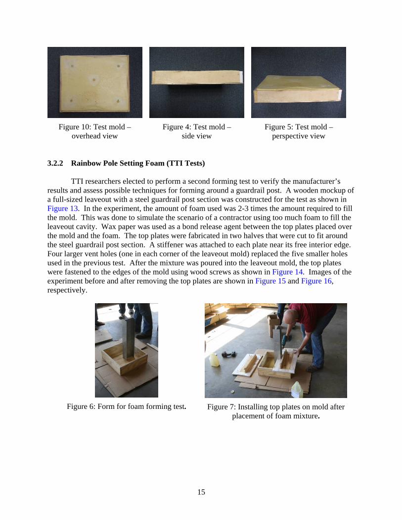
perspective view 3.2.2 Rainbow Pole Setting Foam (TTI Tests) TTI researchers elected to perform a second forming test to verify the manufacturer’s results and assess possible techniques for forming around a guardrail post. A wooden mockup of a full-sized leaveout with a steel guardrail post section was constructed for the test as shown in Figure 13. In the experiment, the amount of foam used was 2-3 times the amount required to fill the mold. This was done to simulate the scenario of a contractor using too much foam to fill the leaveout cavity. Wax paper was used as a bond release agent between the top plates placed over the mold and the foam. The top plates were fabricated in two halves that were cut to fit around the steel guardrail post section. A stiffener was attached to each plate near its free interior edge. Four larger vent holes (one in each corner of the leaveout mold) replaced the five smaller holes used in the previous test. After the mixture was poured into the leaveout mold, the top plates were fastened to the edges of the mold using wood screws as shown in Figure 14. Images of the experiment before and after removing the top plates are shown in Figure 15 and Figure 16, respectively.
Figure 6: Form for foam forming test. Figure 7: Installing top plates on mold after
placement of foam mixture.
15
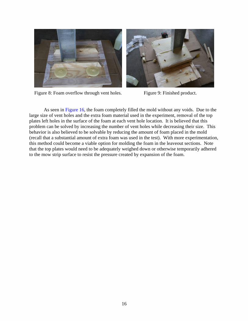
Figure 8: Foam overflow through vent holes. Figure 9: Finished product. As seen in Figure 16, the foam completely filled the mold without any voids. Due to the large size of vent holes and the extra foam material used in the experiment, removal of the top plates left holes in the surface of the foam at each vent hole location. It is believed that this problem can be solved by increasing the number of vent holes while decreasing their size. This behavior is also believed to be solvable by reducing the amount of foam placed in the mold (recall that a substantial amount of extra foam was used in the test). With more experimentation, this method could become a viable option for molding the foam in the leaveout sections. Note that the top plates would need to be adequately weighed down or otherwise temporarily adhered to the mow strip surface to resist the pressure created by expansion of the foam.
16
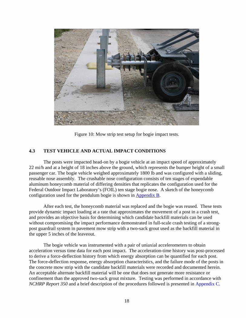
4. DYNAMIC BOGIE VEHICLE IMPACT TESTS 4.1 TEST PLAN To evaluate the impact performance of the selected products, a series of dynamic bogie vehicle impact tests were conducted. A concrete mow strip test section was constructed for the test program. W6x8.5 steel guardrail posts were installed in leaveout sections formed in the concrete mow strip at a standard spacing of 6 ft-3 in. Various backfill treatments were applied around the posts. These included a two-part urethane foam, two recycled rubber mat products, a pop-out concrete wedge, and the standard two-sack grout, which was used as a baseline for comparison with other products. The 1800-lb bogie vehicle impacted the posts headon at a nominal speed of 22 mi/h. An accelerometer on the bogie vehicle was used to measure its acceleration-time history, from which force-time histories were developed. 4.2 TEST ARTICLE DESIGN AND CONSTRUCTION A 25-ft long x 3.5-ft wide x 5-inch thick concrete mow strip was constructed on top of 6 inches of compacted road base material. A riprap concrete with a minimum 28-day compressive strength of 2000 psi was used for the mow strip. The concrete was minimally reinforced with welled-wire mesh to control shrinkage cracking. The length of the mow strip was designed to accommodate four guardrail posts at a spacing of 6 ft-3 inches, which is the standard spacing in a strong-post guardrail system. The posts were embedded to a standard depth of 3 ft-8 inches in 12-inch diameter augured holes. The holes were backfilled with NCHRP Report 350 standard soil. The posts were positioned approximately 3 inches from the front edge of an 18-inch x 18-inch leave-out section. The candidate backfill materials were use in the top portion of the leave-out section. Five full scale bogie tests were performed. The first test was performed on the current standard two-sack grout to establish a performance baseline. Two types of rubber mats submitted by Welch products were tested. One was the TopHat™ and the other was a flat mat. For the TopHat,™ the soil was backfilled to within 5 inches of the top surface of the pavement mow strip. The product was slid over the post and had an inside perimeter that fit inside the leaveout void. For the flat mat, the soil was backfilled to the surface of the concrete mow strip and the product rested on the soil and surrounding concrete. A two-part urethane foam from Rainbow Technologies and full-strength pop-out concrete wedge were also included in the test matrix. Figure 17 shows a photograph of the test setup. A set of detailed construction drawings can be found in Appendix A.
17
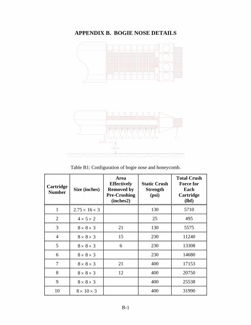
Figure 10: Mow strip test setup for bogie impact tests. 4.3 TEST VEHICLE AND ACTUAL IMPACT CONDITIONS The posts were impacted head-on by a bogie vehicle at an impact speed of approximately 22 mi/h and at a height of 18 inches above the ground, which represents the bumper height of a small passenger car. The bogie vehicle weighed approximately 1800 lb and was configured with a sliding, reusable nose assembly. The crushable nose configuration consists of ten stages of expendable aluminum honeycomb material of differing densities that replicates the configuration used for the Federal Outdoor Impact Laboratory’s (FOIL) ten stage bogie nose. A sketch of the honeycomb configuration used for the pendulum bogie is shown in Appendix B. After each test, the honeycomb material was replaced and the bogie was reused. These tests provide dynamic impact loading at a rate that approximates the movement of a post in a crash test, and provides an objective basis for determining which candidate backfill materials can be used without compromising the impact performance demonstrated in full-scale crash testing of a strong-post guardrail system in pavement mow strip with a two-sack grout used as the backfill material in the upper 5 inches of the leaveout. The bogie vehicle was instrumented with a pair of uniaxial accelerometers to obtain acceleration versus time data for each post impact. The acceleration-time history was post-processed to derive a force-deflection history from which energy absorption can be quantified for each post. The force-deflection response, energy absorption characteristics, and the failure mode of the posts in the concrete mow strip with the candidate backfill materials were recorded and documented herein. An acceptable alternate backfill material will be one that does not generate more resistance or confinement than the approved two-sack grout mixture. Testing was performed in accordance with NCHRP Report 350 and a brief description of the procedures followed is presented in Appendix C.
18
4.4 WEATHER CONDITIONS The bogie tests were performed July 14 and 15, 2008. Seven days prior to the first test a total of 0.27 inches of rainfall was recorded. That was the only rainfall recorded within one week of the test date. During testing, the wind speed was 4 mi/h, wind direction was 270 degrees with respect to the bogie, temperature ranged from 86-93°F, and relative humidity ranged from 46-66 percent. 4.5 TEST DESCRIPTION 4.5.1 Test B1 The leaveout with two-sack grout is shown in Figure 18 prior to the test. At the time of testing, the grout had a compressive strength of 73.6 psi. The bogie vehicle impacted the W6x8.5 steel post headon at a speed of 20.9 mi/h. At approximately 0.007 s after impact, the post began to deflect toward the field side of the mow strip, and at 0.052 s, the front of the bogie began to ride up on the post. The post began to rotate clockwise at 0.081 s, and the bogie lost contact with the post at 0.138 s. The speed of the bogie at this time was 8.9 mi/h. The bogie continued forward motion and landed atop the post.
Figure 18: Leaveout with two-sack grout prior to test B1.
19
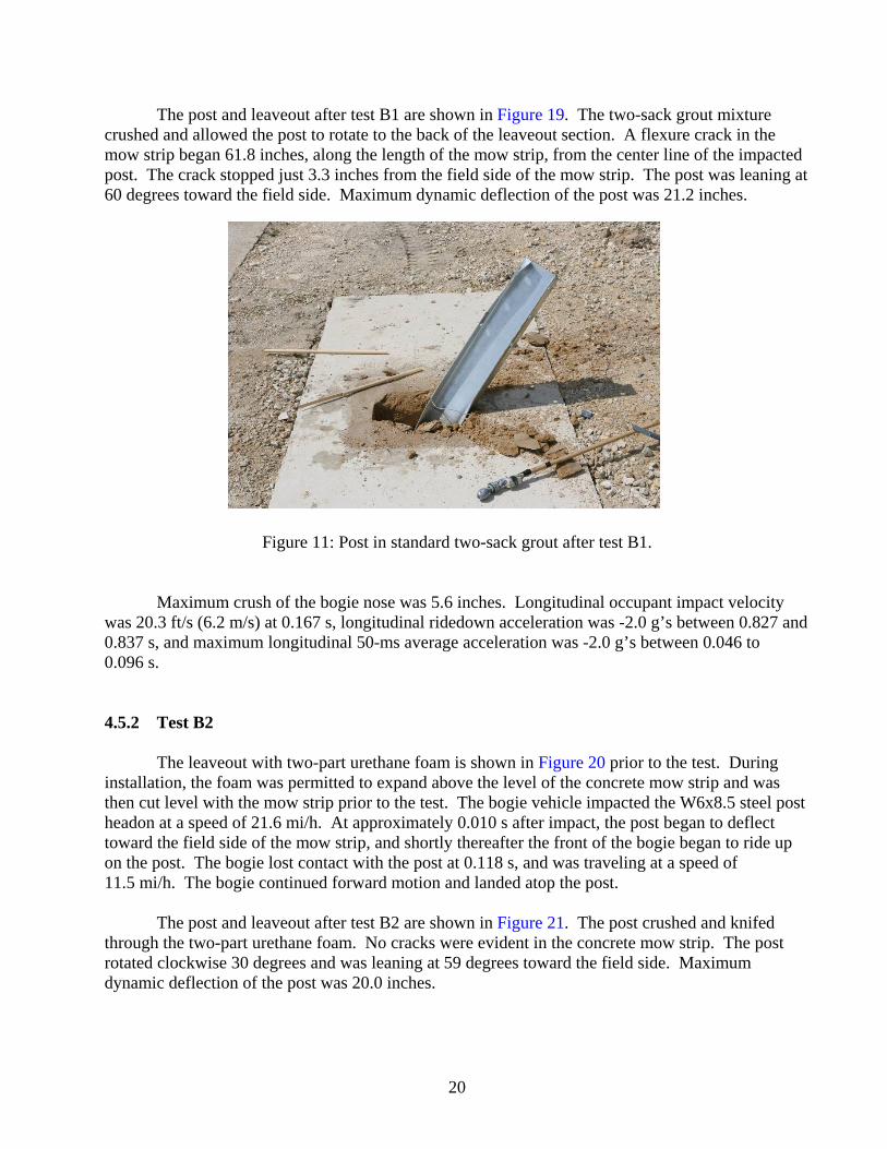
The post and leaveout after test B1 are shown in Figure 19. The two-sack grout mixture crushed and allowed the post to rotate to the back of the leaveout section. A flexure crack in the mow strip began 61.8 inches, along the length of the mow strip, from the center line of the impacted post. The crack stopped just 3.3 inches from the field side of the mow strip. The post was leaning at 60 degrees toward the field side. Maximum dynamic deflection of the post was 21.2 inches.
Figure 11: Post in standard two-sack grout after test B1. Maximum crush of the bogie nose was 5.6 inches. Longitudinal occupant impact velocity was 20.3 ft/s (6.2 m/s) at 0.167 s, longitudinal ridedown acceleration was -2.0 g’s between 0.827 and 0.837 s, and maximum longitudinal 50-ms average acceleration was -2.0 g’s between 0.046 to 0.096 s. 4.5.2 Test B2 The leaveout with two-part urethane foam is shown in Figure 20 prior to the test. During installation, the foam was permitted to expand above the level of the concrete mow strip and was then cut level with the mow strip prior to the test. The bogie vehicle impacted the W6x8.5 steel post headon at a speed of 21.6 mi/h. At approximately 0.010 s after impact, the post began to deflect toward the field side of the mow strip, and shortly thereafter the front of the bogie began to ride up on the post. The bogie lost contact with the post at 0.118 s, and was traveling at a speed of 11.5 mi/h. The bogie continued forward motion and landed atop the post. The post and leaveout after test B2 are shown in Figure 21. The post crushed and knifed through the two-part urethane foam. No cracks were evident in the concrete mow strip. The post rotated clockwise 30 degrees and was leaning at 59 degrees toward the field side. Maximum dynamic deflection of the post was 20.0 inches.
20
Figure 20: Post in two part urethane foam prior to test B2.
Figure 21: Post in two part urethane foam after test B2. Maximum crush of the bogie nose was 5.8 inches. Longitudinal occupant impact velocity was 17.4 ft/s (5.3 m/s) at 0.178 s, longitudinal ridedown acceleration was -2.2 g’s between 0.209 and 0.219 s, and maximum longitudinal 50-ms average acceleration was -6.2 g’s between 0.027 to 0.077 s. 4.5.3 Test B3 The leaveout with full-strength pop-out concrete wedge is shown in Figure 22 prior to the test. The bogie vehicle impacted the W6x8.5 steel post at an impact speed of 21.1 mi/h. At
21
approximately 0.007 s after impact, the post began to deflect toward the field side of the mow strip, and at 0.027 s, the unreinforced concrete began to crack behind the post. The unreinforced concrete began to rise up from the leave-out at 0.027 s, and the front of the bogie began to ride up on the post 0.044 s. The bogie lost contact with the post at 0.132 s, at which time the speed of the bogie was 10.2 mi/h. The bogie continued forward motion and landed atop the post.
Figure 22: Post in full-strength unreinforced concrete wedge prior to test B3. The post and leaveout after test B3 are shown in Figure 23. The concrete wedge cracked and popped up and out of the leaveout section. No cracks were evident in the mow strip, but the unreinforced concrete wedge in the leave-out was broken into several pieces. The post was leaning 60 degrees toward the field side. Maximum dynamic deflection of the post was 21.3 inches.
Figure 23: Post in full-strength unreinforced concrete wedge after test B3.
22
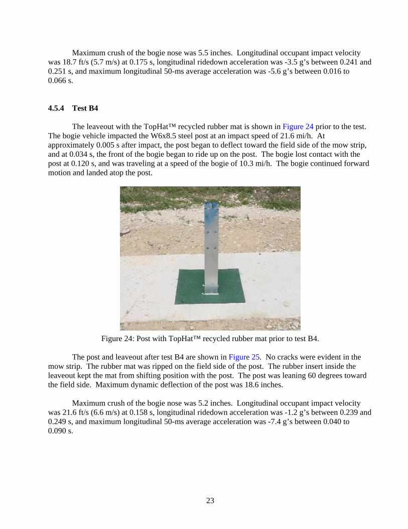
Maximum crush of the bogie nose was 5.5 inches. Longitudinal occupant impact velocity was 18.7 ft/s (5.7 m/s) at 0.175 s, longitudinal ridedown acceleration was -3.5 g’s between 0.241 and 0.251 s, and maximum longitudinal 50-ms average acceleration was -5.6 g’s between 0.016 to 0.066 s. 4.5.4 Test B4 The leaveout with the TopHat™ recycled rubber mat is shown in Figure 24 prior to the test. The bogie vehicle impacted the W6x8.5 steel post at an impact speed of 21.6 mi/h. At approximately 0.005 s after impact, the post began to deflect toward the field side of the mow strip, and at 0.034 s, the front of the bogie began to ride up on the post. The bogie lost contact with the post at 0.120 s, and was traveling at a speed of the bogie of 10.3 mi/h. The bogie continued forward motion and landed atop the post.
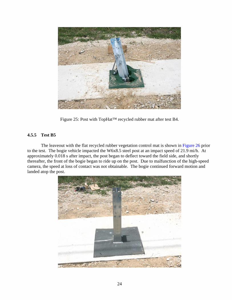
Figure 24: Post with TopHat™ recycled rubber mat prior to test B4. The post and leaveout after test B4 are shown in Figure 25. No cracks were evident in the mow strip. The rubber mat was ripped on the field side of the post. The rubber insert inside the leaveout kept the mat from shifting position with the post. The post was leaning 60 degrees toward the field side. Maximum dynamic deflection of the post was 18.6 inches. Maximum crush of the bogie nose was 5.2 inches. Longitudinal occupant impact velocity was 21.6 ft/s (6.6 m/s) at 0.158 s, longitudinal ridedown acceleration was -1.2 g’s between 0.239 and 0.249 s, and maximum longitudinal 50-ms average acceleration was -7.4 g’s between 0.040 to 0.090 s.
23
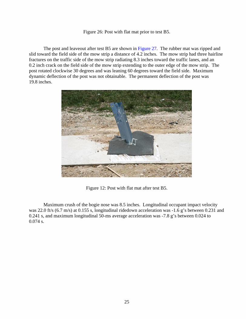
Figure 25: Post with TopHat™ recycled rubber mat after test B4. 4.5.5 Test B5 The leaveout with the flat recycled rubber vegetation control mat is shown in Figure 26 prior to the test. The bogie vehicle impacted the W6x8.5 steel post at an impact speed of 21.9 mi/h. At approximately 0.018 s after impact, the post began to deflect toward the field side, and shortly thereafter, the front of the bogie began to ride up on the post. Due to malfunction of the high-speed camera, the speed at loss of contact was not obtainable. The bogie continued forward motion and landed atop the post.
24
Figure 26: Post with flat mat prior to test B5. The post and leaveout after test B5 are shown in Figure 27. The rubber mat was ripped and slid toward the field side of the mow strip a distance of 4.2 inches. The mow strip had three hairline fractures on the traffic side of the mow strip radiating 8.3 inches toward the traffic lanes, and an 0.2 inch crack on the field side of the mow strip extending to the outer edge of the mow strip. The post rotated clockwise 30 degrees and was leaning 60 degrees toward the field side. Maximum dynamic deflection of the post was not obtainable. The permanent deflection of the post was 19.8 inches.
Figure 12: Post with flat mat after test B5. Maximum crush of the bogie nose was 8.5 inches. Longitudinal occupant impact velocity was 22.0 ft/s (6.7 m/s) at 0.155 s, longitudinal ridedown acceleration was -1.6 g’s between 0.231 and 0.241 s, and maximum longitudinal 50-ms average acceleration was -7.8 g’s between 0.024 to 0.074 s.
25
27
5. DISCUSSION OF RESULTS FROM BOGIE VEHICLE IMPACT TESTING
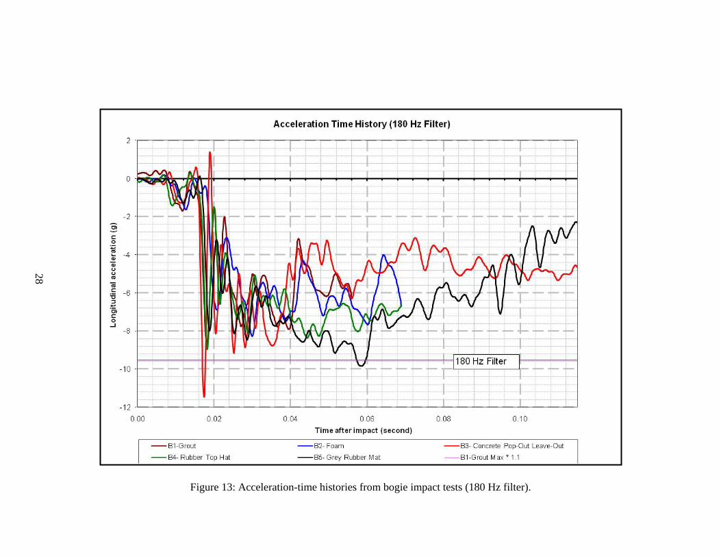
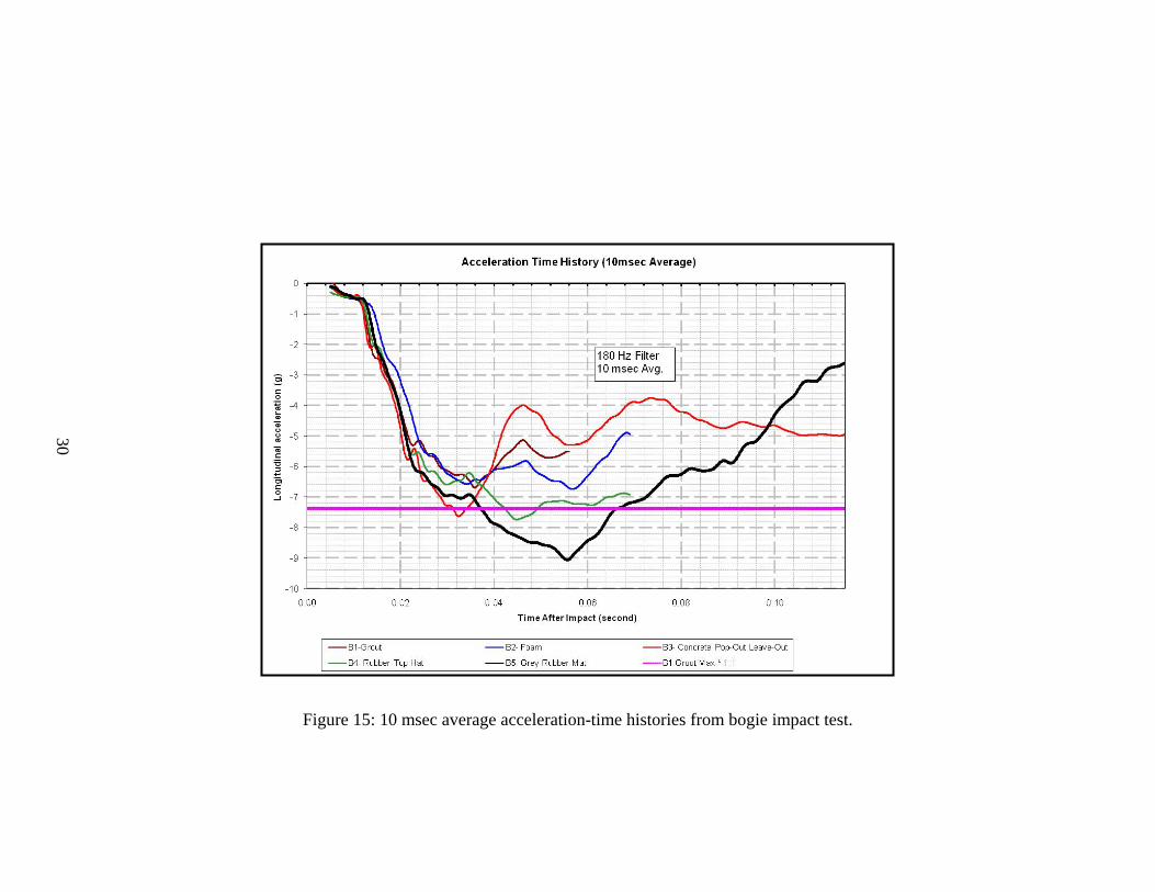
Figure 28 shows the raw acceleration data for all 5 tests. The horizontal line shown in the figure represents a 10% amplification of the maximum acceleration recorded in the base line test with the two-sack grout. This was considered to be a reasonable, albeit somewhat arbitrary, threshold value for evaluation of the impact performance of the candidate mow strip products. All of the acceleration-time histories have a similar trend. Two of the curves (full-strength pop-out concrete wedge and flat recycled rubber mat) have peak accelerations that exceed the 10% amplification of the base line peak. However, since the threshold is somewhat arbitrary and the duration of the acceleration spikes exceeding the threshold are very short, the researchers felt that these two options are still viable. Figure 29 shows the corresponding force-time histories for the bogie vehicle impact tests. Because these curves are obtained by multiplying the mass of the bogie vehicle and the measured acceleration data, they show the same trends as the acceleration-time histories. Figure 30 shows the 10-ms moving average of the acceleration-time histories measured in the bogie impact tests. The 10-ms average is considered to be a more suitable duration for design than the instantaneous acceleration values. There are three products (concrete pop-out wedge, rubber top hat, and flat rubber mat) have 10-ms average accelerations that exceed the 10% amplification of the peak 10-ms average acceleration of the base line test with the two-sack grout . The concrete pop-out wedge and rubber top hat only exceed the baseline threshold for a short duration by 3% and 5%, respectively. The flat rubber mat on the other hand exceeds the 10% amplification of the baseline for 0.028 sec, which is approximately 1/5 of the recorded acceleration trace. Further, the peak 10-ms average acceleration for the flat rubber mat exceeds the baseline threshold by 22%. This leads the researchers to conclude that the flat rubber mat cannot be recognized as an alternative to the two-sack grout without further testing and evaluation. Figure 31 is a graph of the energy-time histories for each product tested. All the products display similar energy dissipation characteristics up to approximately 0.04 seconds. After this time, there is more energy dissipated by the flat mat than the other products. The thin mat itself does not provide any significant resistance to post movement. Rather, it is the soil confined within the leaveout. In the test of the flat mat, the standard soil was compacted to the top of the leaveout without any void space to support the flat mat. The added height and confinement of the soil led to acceleration levels that exceeded those of the baseline two-sack grout mixture. The pop-out concrete wedge was observed to have the lowest level of energy dissipation among the products tested. As shown in Figure 30, a relatively large, short duration force is required to lift the concrete wedge out of the leaveout. However, once displaced, the wedge does not offer any further resistance to post rotation. The other products, on the other hand, continue to resist post movement to varying degrees throughout the impact event and, thus, have higher levels of energy dissipation.
Figure 14: Force-time histories from bogie impact tests.
30
Figure 15: 10 msec average acceleration-time histories from bogie impact test.
Figure 16: Energy time history.
31
6. SUMMARY AND RECOMMENDATIONS 6.1 SUMMARY Static laboratory and dynamic bogie impact testing was conducted to evaluate several products for use around guardrail posts encased in a pavement mow strip. A two-sack grout mixture that had been successfully crash tested under a previous research study was used as a baseline reference for acceptable impact performance. The basis of the evaluation was that if a candidate product offered resistance to post movement in the leave out section that was equal to or less than that of the two-sack grout, it could be considered an acceptable alternative without the need for further crash testing. The products that were investigated include a two-part urethane foam, a molded rubber product that has an insert fabricated to match the size of the leaveout, a flat recycled rubber mat that rests on top of a leave out backfilled with soil, and a new pop-out concrete wedge conceived under this project. All of the products except the flat rubber mat are considered to have acceptable impact performance. The acceleration levels associated with the flat rubber mat significantly exceeded the baseline threshold established from the test results of the two-sack grout mixture (see Figure 30). It should be noted that the thin mat itself does not provide any significant resistance to post movement and is not responsible for the high acceleration. Rather, it is the soil confined within the leaveout. To support the flat mat, the standard soil was compacted to the top of the leaveout without any void space. The added height and confinement of the soil led to acceleration levels that exceeded those of the baseline two-sack grout mixture as the soil was compressed between the post and the back face of the leaveout. The other tested products are considered to be acceptable alternatives to the standard two-sack grout mix from an impact performance and vegetation control standpoint. However, they each have their own advantages and disadvantages in regard to installation and inspection. 6.1.1 Two-Part Urethane Foam Two-part urethane foams are readily available from several manufacturers. These foams can be pre-packaged as a two part chemical solution to achieve a desired volume with a specified density and strength. Because it is closed cell, the foam is essentially impermeable to water. Inhibitors should be specified to provide resistance to degradation from ultraviolet (UV) light. The installation of the foam can be somewhat cumbersome. One the two parts are mixed, it must be quickly poured into place before is begins to expand. Further, it is difficult to obtain uniform, unconfined expansion of the foam. Therefore, since any voids or low spots below the grade of the pavement mow strip can collect dirt and possibly lead to some future vegetation growth, it may be necessary to overfill the leave out cavity and later cut the foam level with the ground
33
surface for aesthetic purposes. While the foam is relatively easy to cut using any type of saw blade, the shape of a steel guardrail post can make this task more difficult. Alternatively, a temporary form can be placed across the top of the leave out to confine and produce more even expansion of the foam. However, the temporary form would need to be treated with of bond release agent to prevent adherence of the foam, be properly secured to the pavement mow strip or otherwise weighted down, and have some vent holes to permit the release of foam in the event the leaveout cavity is significantly overfilled. 6.1.2 Rubber Mat with Insert The rubber mat with insert, known as the TopHat™, is available from Welch Products, Inc. It is molded from recycled crumb rubber and is designed to be used as a permanent form around the guardrail post. It can reportedly be manufactured in a variety of colors. The lower portion of the TopHat™ has an insert that is molded to fit inside the perimeter of the leave out. The area inside the insert should be left as void space with no soil backfill. The upper portion of the TopHat™ consists of a 3/8-inch thick mat that extends over the edges of the leaveout to prevent vegetation growth. The mat can be manufactured with a cutout that matches the shape of a particular post (e.g. W6x8.5 steel or 6x8 wood). Alternatively, scribe lines for different post shapes can be incorporated into the mat to facilitate cutting in the field. In either case, the size of the upper mat should be sufficient to overlap onto the pavement mow strip while providing some tolerance for post placement in the leaveout section. Because the TopHat™ is molded in one piece, it must be slid into position over the installed guardrail post, or the post must be driven through it after the TopHat™ is placed in the leaveout. A silicone sealant or other suitable adhesive should be used to help seal the perimeter of the mat to the post and pavement mow strip. 6.1.3 Pop-Out Wedge Concrete The pop-out concrete wedge permits the use of conventional concrete as a backfill material in the leaveout section around the post. The leaveout is constructed with a modified geometry that provides an opportunity for the concrete to displace or “pop-out” of the leaveout during an impact. The two sides and rear edge of the leaveout are chamfered at a 45 deg angle to allow the concrete wedge to be pushed up and out of the leaveout upon loading from the post. The post is then free to rotate within the leaveout without any further resistance from the backfill material. Note that a bond breaking material must be applied to all of the internal faces of the leaveout to permit the backfill material to readily release from the surrounding pavement mow strip. In the bogie test, roofing tar paper was used as a bond breaker and conventional concrete was used as the backfill material.
34
35
The use of conventional strength concrete eliminates the difficulty associated with the quality control and inspection of the two-sack grout mixture. However, it does require that the leaveout be inspected prior to placement of the concrete backfill to verify proper geometry and application of a bond breaker. 6.2 RECOMMENDATIONS The two-part urethane foam, rubber mat with molded insert, and pop-out concrete wedge are all considered suitable for implementation based on an evaluation of their impact performance. Each of these products has its own advantages and disadvantages in terms of cost, availability, ease of inspection, and installation. It is recommended that some field experience be gained with one or more of these products to better assess which would provide the most cost-effective solution for a particular user agency. It should be noted that the long term durability of these products was not evaluated. Field experience is necessary to assess their long-term durability in the highway environment.
37
REFERENCES
1. Baxter, J. R., “W-Beam Guardrail Installations in Rock and in Mowing Strips,” Memorandum HAS-10/B64-B, Federal Highway Administration, U.S. Department of Transportation, March 10, 2004.
2. Bligh, R. P., Seckinger, N. R., Abu-Odeh, A. Y., Roschke, P. N., Menges, W. L., and Haug, R. R., “Dynamic Response of Guardrail Systems Encased in Pavement Mow Strips,” Research Report 0-4162-2, Texas Transportation Institute, College Station, TX, January 2004.
3. Ross, H. E., Jr., Sicking, D. L., Zimmer, R. A., and Michie, J. D., “Recommended Procedures for the Safety Performance Evaluation of Highway Features,” National Cooperative Highway Research Program Report 350, Transportation Research Board, National Research Council, Washington, D.C., 1993.
APPENDIX A. TEST ARTICLE DETAILS A
PPEND
IX A
. TEST AR
TICLE
DETA
ILS
A-1
A-2
A-3
A-4
A-5
APPENDIX B. BOGIE NOSE DETAILS
Table B1: Configuration of bogie nose and honeycomb.
Cartridge Number Size (inches)
Area Effectively
Removed by Pre-Crushing
(inches2)
Static Crush Strength
(psi)
Total Crush Force for
Each Cartridge
(lbf)
1 2.75 × 16 × 3 130 5710
2 4 × 5 × 2 25 495
3 8 × 8 × 3 21 130 5575
4 8 × 8 × 3 15 230 11240
5 8 × 8 × 3 6 230 13308
6 8 × 8 × 3 230 14680
7 8 × 8 × 3 21 400 17153
8 8 × 8 × 3 12 400 20750
9 8 × 8 × 3 400 25538
10 8 × 10 × 3 400 31990
B-1
APPENDIX C. BOGIE TEST PROCEDURES The bogie test and data analysis procedures followed under this project were in accordance with guidelines presented in NCHRP Report 350. Brief descriptions of these procedures are presented as follows. C.1 ELECTRONIC INSTRUMENATION AND DATA PROCESSING The bogie was instrumented with two accelerometers mounted at the rear of the bogie to measure longitudinal acceleration levels. The accelerometers were strain gage type with a linear millivolt output proportional to acceleration. The electronic signals from the accelerometers were amplified and transmitted to a base station by means of constant bandwidth FM/FM telemetry link for recording on magnetic tape and for display on a real-time strip chart. Calibration signals were recorded before and after the test and an accurate time reference signal was simultaneously recorded with the data. Pressure sensitive switches on the nose of the bogie were actuated by wooden dowel rods and initial contact to produce speed trap and "event" marks on the data record to establish the exact instant of contact with the installation, as well as impact velocity. The multiplex of data channels, transmitted on one radio frequency, is received and demultiplexed onto TEAC® instrumentation data recorder. After the test, the data are played back from the TEAC® recorder and digitized. A proprietary software program (WinDigit) converts the analog data from each transducer into engineering units using the R-cal and pre-zero values at 10,000 samples per second, per channel. WinDigit also provides Society of Automotive Engineers (SAE) J211 class 180 phaseless digital filtering and bogie impact velocity. The Test Risk Assessment Program (TRAP) uses the data from WinDigit to compute occupant/compartment impact velocities, time of occupant/compartment impact after bogie impact, and the highest 10-ms average ridedown acceleration. WinDigit calculates change in bogie velocity at the end of a given impulse period. In addition, maximum average accelerations over 50-ms are computed. For reporting purposes, the data from the bogie-mounted accelerometers were then filtered with a 180 Hz digital filter and plotted using a commercially available software package (Microsoft EXCEL). C.2 PHOTOGRAPHIC INSTRUMENATION AND DATA PROCESSING A high-speed digital camera, positioned perpendicular to the path of the bogie and the test article, was used to record the collision period. The film from this high-speed camera was analyzed on a computer to observe phenomena occurring during the collision and to obtain time-event, displacement, and angular data. A mini-DV camera and still cameras were used to document the crushable pendulum nose and the test article before and after the test.