NTHZ DOUBLE INLET CENTRIFUGAL FANS WITH BACKWARD CURVED BLADES ZWEISEITIGSAUGENDE RADIALVENTILATOREN MIT RÜCKWÄRTSGEKRÜMMTEN SCHAUFELN VENTILATEURS CENTRIFUGES DOUBLE ASPIRATION AVEC AUBES COURBÉES VERS L’ARRIÈRE VENTILATORI CENTRIFUGHI A DOPPIA ASPIRAZIONE A PALE ROVESCE
Transcript
NTHZ
DOUBLE INLET CENTRIFUGAL FANS WITH BACKWARD CURVED BLADES
ZWEISEITIGSAUGENDE RADIALVENTILATOREN MIT RÜCKWÄRTSGEKRÜMMTEN SCHAUFELN
VENTILATEURS CENTRIFUGES DOUBLE ASPIRATION AVEC AUBES COURBÉES VERS L’ARRIÈRE
VENTILATORI CENTRIFUGHI A DOPPIA ASPIRAZIONE A PALE ROVESCE
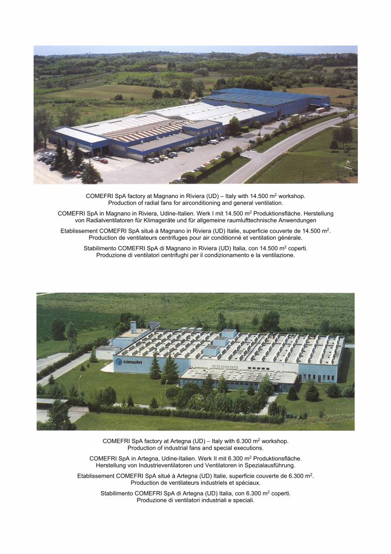
COMEFRI SpA factory at Magnano in Riviera (UD) – Italy with 14.500 m2 workshop.
Production of radial fans for airconditioning and general ventilation.
COMEFRI SpA in Magnano in Riviera, Udine-Italien. Werk I mit 14.500 m2 Produktionsfläche. Herstellung von Radialventilatoren für Klimageräte und für allgemeine raumlufttechnische Anwendungen
Etablissement COMEFRI SpA situé à Magnano in Riviera (UD) Italie, superficie couverte de 14.500 m2. Production de ventilateurs centrifuges pour air conditionné et ventilation générale.
Stabilimento COMEFRI SpA di Magnano in Riviera (UD) Italia, con 14.500 m2 coperti. Produzione di ventilatori centrifughi per il condizionamento e la ventilazione.
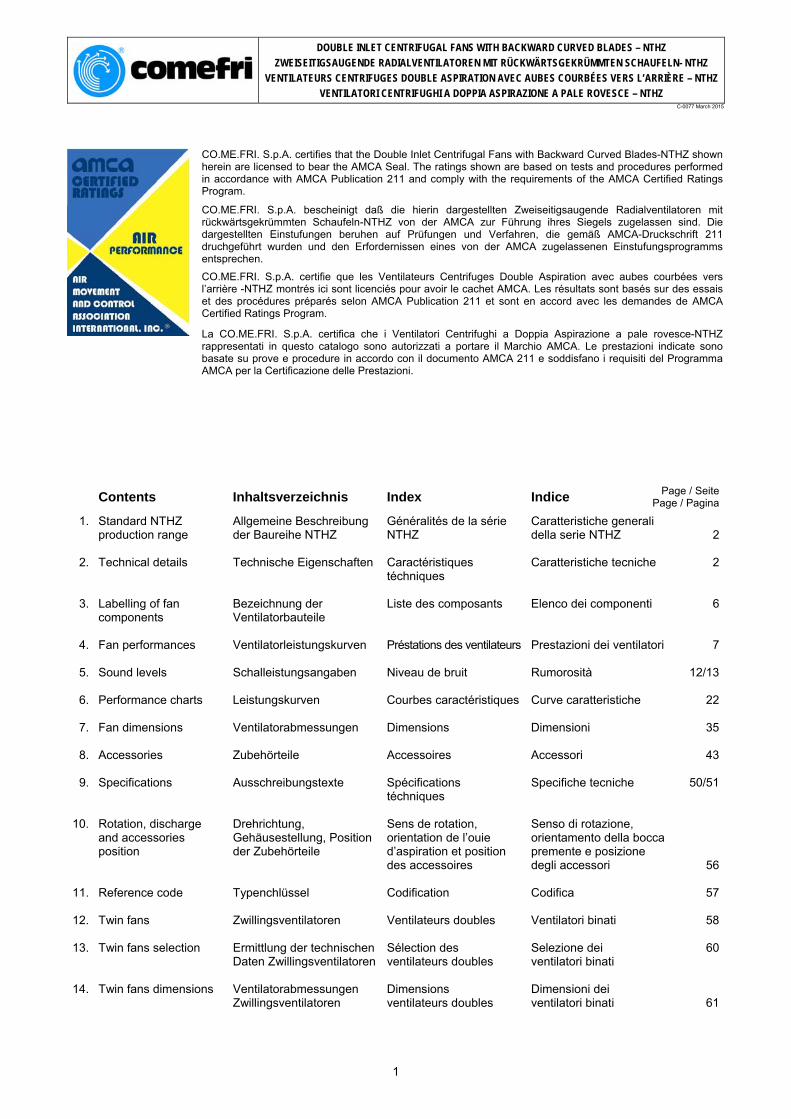
COMEFRI SpA factory at Artegna (UD) – Italy with 6.300 m2 workshop.
Production of industrial fans and special executions.
COMEFRI SpA in Artegna, Udine-Italien. Werk II mit 6.300 m2 Produktionsfläche. Herstellung von Industrieventilatoren und Ventilatoren in Spezialausführung.
Etablissement COMEFRI SpA situé à Artegna (UD) Italie, superficie couverte de 6.300 m2. Production de ventilateurs industriels et spéciaux.
Stabilimento COMEFRI SpA di Artegna (UD) Italia, con 6.300 m2 coperti. Produzione di ventilatori industriali e speciali.
DOUBLE INLET CENTRIFUGAL FANS WITH BACKWARD CURVED BLADES – NTHZ
ZWEISEITIGSAUGENDE RADIALVENTILATOREN MIT RÜCKWÄRTSGEKRÜMMTEN SCHAUFELN- NTHZ
VENTILATEURS CENTRIFUGES DOUBLE ASPIRATION AVEC AUBES COURBÉES VERS L’ARRIÈRE – NTHZ
VENTILATORI CENTRIFUGHI A DOPPIA ASPIRAZIONE A PALE ROVESCE – NTHZ C-0077 March 2015
CO.ME.FRI. S.p.A. certifies that the Double Inlet Centrifugal Fans with Backward Curved Blades-NTHZ shown herein are licensed to bear the AMCA Seal. The ratings shown are based on tests and procedures performed in accordance with AMCA Publication 211 and comply with the requirements of the AMCA Certified Ratings Program.
CO.ME.FRI. S.p.A. bescheinigt daß die hierin dargestellten Zweiseitigsaugende Radialventilatoren mit rückwärtsgekrümmten Schaufeln-NTHZ von der AMCA zur Führung ihres Siegels zugelassen sind. Die dargestellten Einstufungen beruhen auf Prüfungen und Verfahren, die gemäß AMCA-Druckschrift 211 druchgeführt wurden und den Erfordernissen eines von der AMCA zugelassenen Einstufungsprogramms entsprechen.
CO.ME.FRI. S.p.A. certifie que les Ventilateurs Centrifuges Double Aspiration avec aubes courbées vers l’arrière -NTHZ montrés ici sont licenciés pour avoir le cachet AMCA. Les résultats sont basés sur des essais et des procédures préparés selon AMCA Publication 211 et sont en accord avec les demandes de AMCA Certified Ratings Program.
La CO.ME.FRI. S.p.A. certifica che i Ventilatori Centrifughi a Doppia Aspirazione a pale rovesce-NTHZ rappresentati in questo catalogo sono autorizzati a portare il Marchio AMCA. Le prestazioni indicate sono basate su prove e procedure in accordo con il documento AMCA 211 e soddisfano i requisiti del Programma AMCA per la Certificazione delle Prestazioni.
Contents Inhaltsverzeichnis Index Indice Page / Seite
DOUBLE INLET CENTRIFUGAL FANS WITH BACKWARD CURVED BLADES – NTHZ
ZWEISEITIGSAUGENDE RADIALVENTILATOREN MIT RÜCKWÄRTSGEKRÜMMTEN SCHAUFELN- NTHZ
VENTILATEURS CENTRIFUGES DOUBLE ASPIRATION AVEC AUBES COURBÉES VERS L’ARRIÈRE – NTHZ
VENTILATORI CENTRIFUGHI A DOPPIA ASPIRAZIONE A PALE ROVESCE – NTHZ C-0077 March 2015
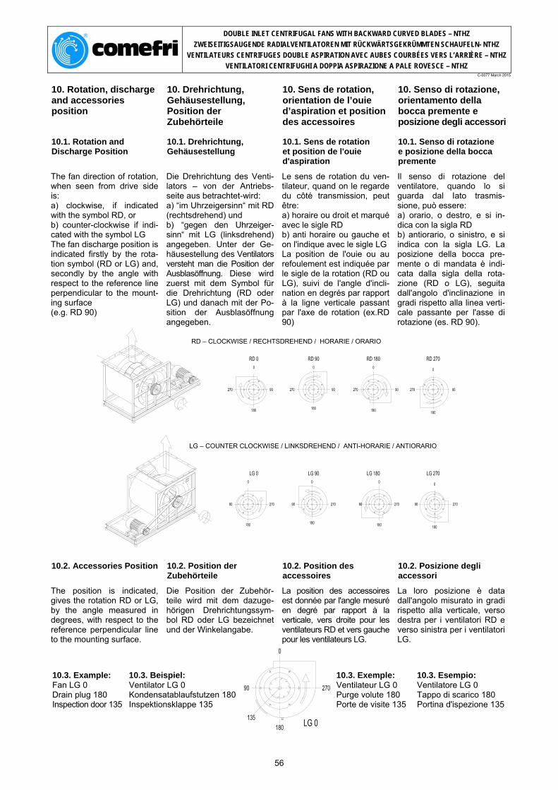
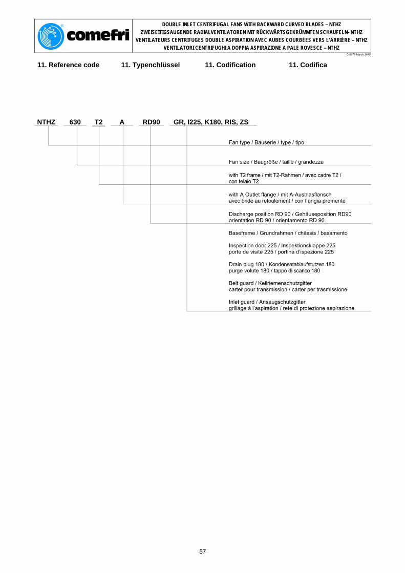
1. Standard NTHZ pro-duction range
1. Allgemeine Beschrei-bung der Baureihe NTHZ
1. Généralités de la série NTHZ
1. Caratteristiche gene-rali della serie NTHZ
Comefri's NTHZ double-inlet-double-width centrifugal fans with backward curved blades series cover a size range from 315 to 1250. All fans within the range have the following characteristics: optimally engineered for HVAC applications; high quality, compact de-sign; high efficiency, low power consumption; quiet operation; fan performances fully tested and certified in Come-fri's own state-of-the-art la-boratory in accordance with DIN, ISO, BS and AMCA standards; Performance data ac-cording to DIN 24166, accu-racy Class 1. standard operating temper-ature between -20°C and +60°C.
Die zweiseitig saugende Comefri Radialventilatorbau-reihe NTHZ mit rückwärtsge-krümmten schaufeln wird in den Baugrößen 315 bis 1250 hergestellt. Alle Ventilatoren dieser Baureihe verfügen über folgende Eigenschaften: Optimierte Kennlinie für die Klimatechnik; Hohe Qualität, kompakte Bauweise; Hohen Wirkungsgrad, nied-rige Leistungsaufnahme; Geräuscharmen Betrieb; Leistungsdaten wurden im Comefri Labor nach DIN, ISO, BS, AMCA Stan-dard gemessen; Ventilatordaten nach DIN 24166, Genauigkeitsklasse1. Standard Betriebstempe-ratur zwischen -20°C und +60°C.
Les ventilateurs centrifuges double aspiration de la série NTHZ ont les turbines avec aubes courbées vers l’arrière et sont construits de la taille 315 à la taille 1250. Tous les ventilateurs de cette gamme ont les caractéristiques sui-vantes: particuliérement adaptes pour la climatisation; niveau de qualité élevé, di-mensions compactes; niveau de rendement élevé, fiable puissance absorbée; silencieux; préstations garanties par d'essais effectués auprés du laboratoire Comefri, selon les normes DIN, ISO, BS et AMCA; courbes selon les normes DIN 24166, Classe de préci-sion 1. température de function-nement standard entre -20°C et +60°C.
I ventilatori centrifughi a dop-pia aspirazione della serie NTHZ hanno le giranti con pale rovesce e sono costruiti nelle grandezze dalla 315 alla 1250. Tutti i ventilatori com-presi in questa gamma hanno le seguenti caratteristiche: particolarmente adatti per la climatizzazione; alta qualità, dimensioni com-patte; alto rendimento, bassa po-tenza assorbita; silenziosità; prestazioni garantite da prove eseguite presso il labo-ratorio Comefri, secondo le norme DIN, ISO, BS e AMCA; curve caratteristiche se-condo le norme DIN 24166, Classe di precisione 1. temperatura di funziona-mento standard tra -20°C e +60°C.
2. Technical details 2.1. Forefinger ®
2. Technische Eigenschaften 2.1. Forefinger ®
2. Caractéristiques téchniques 2.1. Forefinger ®
2. Caratteristiche tecniche 2.1. Forefinger ®
It is an innovative device fully developed and engi-neered by the Aeraulic and Acoustic Test Lab of Comefri (*) (Fig.1). The principle is to exploit the air swirls, always present inside a fan housing. As well known, the recircula-tion of the air streams in-side the fan housing is a major source of losses, decreasing the fan effi-ciency and increasing fan’s noise. This device, called Fore-finger ®, is actively read-dressing this air recircu-lation to the outlet, with a systematic enhancement of the performances, both aeraulic and acoustic.
(*) Patent pending by Comefri
Es handelt sich um eine Inno-vation, entwickelt im Comefri eigenen Labor für Lufttechnik und Akustik.(*) (Bild 1). Die Hauptaufgabe be-steht darin, die internen Ver-luste des Ventilators
Il s’agit d’un dispositif innova-teur étudié et développé par le laboratoire aéraulique et acoustique de Comefri (*) (Fig.1). Son but est de mieux répartir et exploiter le circuit de la volute. En effet, comme nous
Si tratta di un dispositivo innovativo progettato e sviluppato dal Laboratorio Prove Aerauliche ed Acu-stiche della Comefri (*)
(Fig.1). Il suo scopo è quello di ripartire e sfrut-tare i ricircoli d’aria pre-senti all’interno della co-clea. Essi infatti, come noto, essendo la principale causa delle perdite di un ventilatore, ne condizio-nano negativamente il rendimento e ne aumen-tano sensibilmente la ru-morosità. Il dispositivo, denominato Forefinger ®, di fatto è in grado di “intervenire atti-vamente” su tali ricircoli ai fini di un sistematico in-cremento delle prestazioni sia Aerauliche che Acusti-che.
(*) Titolare della relativa domanda di brevetto
(im Gehäuse) zu reduzieren. Diese sind, wie allgemein bekannt, die wichtigste Ur-sache für Ver-luste eines Ventilators und beeinflussen den Wirkungs-grad negativ bei Gleichzeitigem Anstieg des
Fig.1
le signalons, nous constatons que ce phénomène est la principale cause des pertes d’un ventilateur, ce qui conduit à un affaiblissement du rendement et une augmentation sensible du niveau sonore.
Lärmpegel. Mittels des neuen Patent Forefinger ® werden diese Verluste drastisch redu-ziert und somit die Leistungs-daten des Ventilators und auch die Akustik nachhaltig verbes-sert.
(*) zum Patent angemeldet
Ce dispositif ap-pelé Forefinger®, agit active-ment sur le mouvement de l’air, ce qui d’une manière systéma-tique permet d’accroître les performances aéraulique et acoustique.
(*) Titulaire de la relative demande du brevet
2
DOUBLE INLET CENTRIFUGAL FANS WITH BACKWARD CURVED BLADES – NTHZ
ZWEISEITIGSAUGENDE RADIALVENTILATOREN MIT RÜCKWÄRTSGEKRÜMMTEN SCHAUFELN- NTHZ
VENTILATEURS CENTRIFUGES DOUBLE ASPIRATION AVEC AUBES COURBÉES VERS L’ARRIÈRE – NTHZ
VENTILATORI CENTRIFUGHI A DOPPIA ASPIRAZIONE A PALE ROVESCE – NTHZ C-0077 March 2015
2.2. Housing 2.2. Gehäuse 2.2. Volute 2.2. Coclea
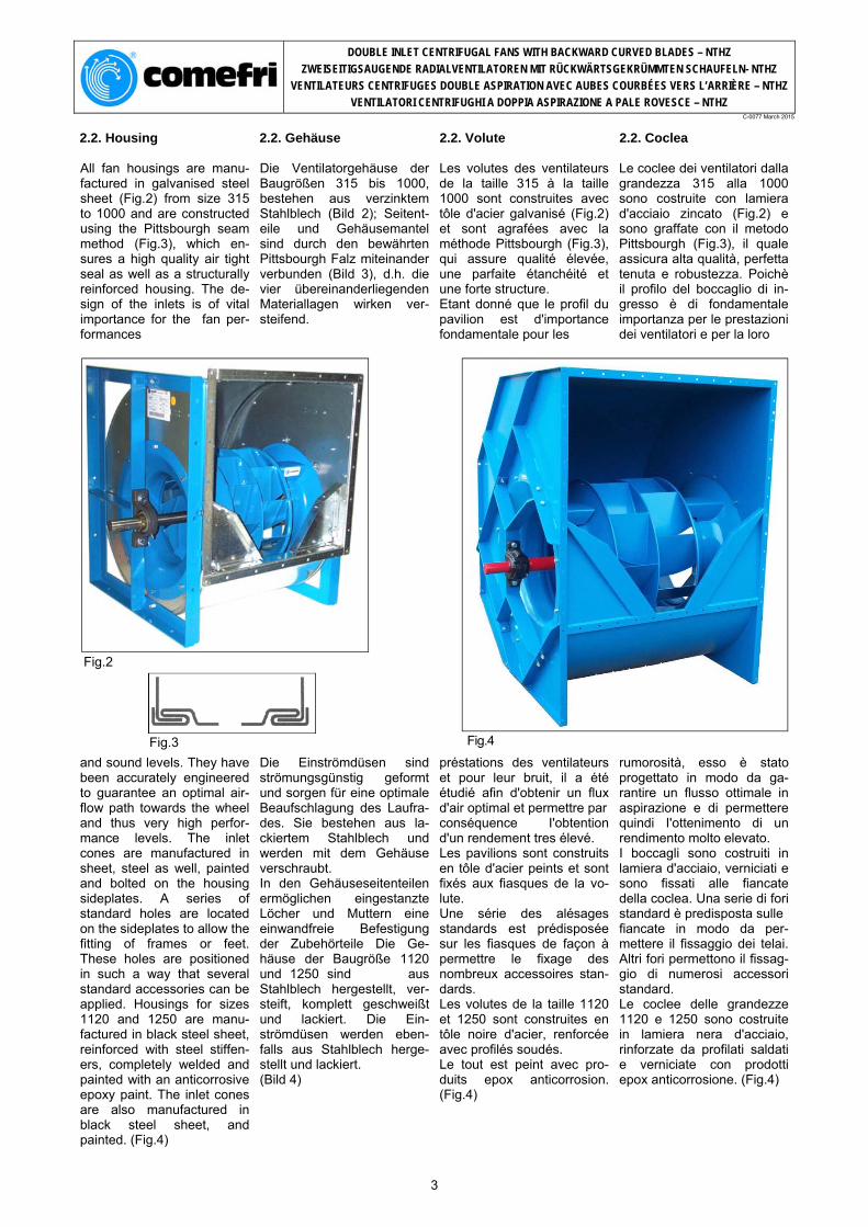
All fan housings are manu-factured in galvanised steel sheet (Fig.2) from size 315 to 1000 and are constructed using the Pittsbourgh seam method (Fig.3), which en-sures a high quality air tight seal as well as a structurally reinforced housing. The de-sign of the inlets is of vital importance for the fan per-formances
Die Ventilatorgehäuse der Baugrößen 315 bis 1000, bestehen aus verzinktem Stahlblech (Bild 2); Seitent-eile und Gehäusemantel sind durch den bewährten Pittsbourgh Falz miteinander verbunden (Bild 3), d.h. die vier übereinanderliegenden Materiallagen wirken ver-steifend.
Les volutes des ventilateurs de la taille 315 à la taille 1000 sont construites avec tôle d'acier galvanisé (Fig.2) et sont agrafées avec la méthode Pittsbourgh (Fig.3), qui assure qualité élevée, une parfaite étanchéité et une forte structure. Etant donné que le profil du pavilion est d'importance fondamentale pour les
Le coclee dei ventilatori dalla grandezza 315 alla 1000 sono costruite con lamiera d'acciaio zincato (Fig.2) e sono graffate con il metodo Pittsbourgh (Fig.3), il quale assicura alta qualità, perfetta tenuta e robustezza. Poichè il profilo del boccaglio di in-gresso è di fondamentale importanza per le prestazioni dei ventilatori e per la loro
Fig.2
Fig.3 Fig.4
and sound levels. They have been accurately engineered to guarantee an optimal air-flow path towards the wheel and thus very high perfor-mance levels. The inlet cones are manufactured in sheet, steel as well, painted and bolted on the housing sideplates. A series of standard holes are located on the sideplates to allow the fitting of frames or feet. These holes are positioned in such a way that several standard accessories can be applied. Housings for sizes 1120 and 1250 are manu-factured in black steel sheet, reinforced with steel stiffen-ers, completely welded and painted with an anticorrosive epoxy paint. The inlet cones are also manufactured in black steel sheet, and painted. (Fig.4)
Die Einströmdüsen sind strömungsgünstig geformt und sorgen für eine optimale Beaufschlagung des Laufra-des. Sie bestehen aus la-ckiertem Stahlblech und werden mit dem Gehäuse verschraubt. In den Gehäuseseitenteilen ermöglichen eingestanzte Löcher und Muttern eine einwandfreie Befestigung der Zubehörteile Die Ge-häuse der Baugröße 1120 und 1250 sind aus Stahlblech hergestellt, ver-steift, komplett geschweißt und lackiert. Die Ein-strömdüsen werden eben-falls aus Stahlblech herge-stellt und lackiert. (Bild 4)
préstations des ventilateurs et pour leur bruit, il a été étudié afin d'obtenir un flux d'air optimal et permettre par conséquence I'obtention d'un rendement tres élevé. Les pavilions sont construits en tôle d'acier peints et sont fixés aux fiasques de la vo-lute. Une série des alésages standards est prédisposée sur les fiasques de façon à permettre le fixage des nombreux accessoires stan-dards. Les volutes de la taille 1120 et 1250 sont construites en tôle noire d'acier, renforcée avec profilés soudés. Le tout est peint avec pro-duits epox anticorrosion. (Fig.4)
rumorosità, esso è stato progettato in modo da ga-rantire un flusso ottimale in aspirazione e di permettere quindi I'ottenimento di un rendimento molto elevato. I boccagli sono costruiti in lamiera d'acciaio, verniciati e sono fissati alle fiancate della coclea. Una serie di fori standard è predisposta sulle fiancate in modo da per-mettere il fissaggio dei telai. Altri fori permettono il fissag-gio di numerosi accessori standard. Le coclee delle grandezze 1120 e 1250 sono costruite in lamiera nera d'acciaio, rinforzate da profilati saldati e verniciate con prodotti epox anticorrosione. (Fig.4)
3
DOUBLE INLET CENTRIFUGAL FANS WITH BACKWARD CURVED BLADES – NTHZ
ZWEISEITIGSAUGENDE RADIALVENTILATOREN MIT RÜCKWÄRTSGEKRÜMMTEN SCHAUFELN- NTHZ
VENTILATEURS CENTRIFUGES DOUBLE ASPIRATION AVEC AUBES COURBÉES VERS L’ARRIÈRE – NTHZ
VENTILATORI CENTRIFUGHI A DOPPIA ASPIRAZIONE A PALE ROVESCE – NTHZ C-0077 March 2015
This high performance im-peller is manufactured in cor-rosion proof steel, with welded backward curved blades. All wheels are coated with epoxy paint (Fig.5), balanced both stati-cally and dynamically to an accuracy grade of G = 2.5 in accordance to DIN ISO 1940-1 (VDI 2060). The impellers are secured to the shaft through a steel or aluminium hub (alumin-ium is used from 315 B/R to 710 B/R and from 315 T1 to 630 T1). Hub bore is pre-cision machined and incor-porates a keyway and lock-ing screw.
Die Hochleistungslaufräder sind aus hochwertigem, kor-rosionsbeständigem Stahl, mit geschweißten, rück-wärtsgekrümmten Schau-feln hergestellt. Alle Laufrä-der sind mit Epoxlack be-schichtet (Bild 5). Sie sind statisch und dynamisch in Gütestufe G=2,5 ausge-wuchtet, gemäß DIN ISO 1940-1 (VDI 2060). Die Laufräder sind mit der Welle durch eine Stahl-bzw. Aluminiumnabe verbunden (Aluminiumnabe: Baugrö-ßen 315 bis 710 Ausfüh-rungen B und R, Baugrößen 315 bis 630 Ausführung T1). Die Nabenbohrungen sind mit einer Passfedernut und einer Befestigungsschraube ausgerüstet.
Ces turbines à rendement élevés sont construites en acier résistant à la corrosion et ont les aubes soudées et courbées vers I'arrière. Toutes les turbines sont re-vêtues d'une couche de peinture epox (Fig.5). Elles sont équilibrées stati-quement et dynamiquement avec un degré de tolérance G=2,5 selon les normes DIN ISO 1940-1 (VDI 2060). Les turbines sont fixées à I'arbre à I'aide de moyeuxmunis de clavette et vis de blocage. Les moyeux sont en aluminium pour les modéles du 315 B/R au 710 B/R et du 315 T1 au 630 T1. Pour les autres modéles ils sont en acier.
Queste giranti ad alto ren-dimento sono costruite in acciaio resistente alla cor-rosione, con pale saldate curvate all'indietro e verni-ciate con smalto epox (Fig.5). Esse sono bilanciate stati-camente e dinamicamente con un grado tolleranza G = 2,5 secondo le norme DIN ISO 1940-1 (VDI 2060). Le giranti sono calettate all'albero tramite mozzi mu-niti di linguetta e vite di ser-raggio. I mozzi sono in alluminio nei modelli dal 315 B/R al 710 B/R, e dal 315 T1 al 630 T1. Negli altri modelli sono in acciaio.
Fig.5
2.4. Shafts 2.4. Wellen 2.4. Arbres 2.4. Alberi
All shafts are designed with a high safety factor and with the first critical speed well beyond to the maximum fan speed. Made in hardened steel, they are precision ground and polished. Shafts are provided with keyways for the wheel hub and for belt pulleys that can be fitted on either shaft ends. All shafts are coated with protective paint for added protection prior to shipping.
Alle Wellen sind mit einem hohen Sicherheitsfaktor be-rechnet. Dabei liegt die ma-ximal zulässige Drehzahl weit unter der ersten kriti-schen Drehzahl. Die geschliffenen Wellen sind aus hochwertigem Stahl hergestellt. Die Verbindung von Lauf-rad/Welle und Keilriemen-scheibe/Welle erfolgt mittels Nut und Feder. Alle Wellen werden mit Rostschutzlack geschützt.
Tous les arbres sont dimen-sionnés avec un coefficient de sécurité élevé. La vitesse maximale admise est bien in-férieure à la vitesse critique. Ils sont construits en acier au car-bone, usinés et réctifiés. Les arbres ont une clavette en correspondence au moyeu de la turbine et une autre cla-vette à chaque extémité, de façon que la poulie puisse être montée indifféremment d'une côté ou de I'autre. Tous les arbres sont couverts avec une peinture protective.
Tutti gli alberi sono dimen-sionati con un elevato coefficiente di sicurezza ed una velocità critica lar-gamente superiore alla massima velocità di fun-zionamento consentita. Sono costruiti in acciaio al carbonio, torniti e rettificati. Gli alberi hanno una sede linguetta in corrispondenza del mozzo della girante ed un'altra ad ogni estremità. Tutti gli alberi sono rivestiti con una vernice protettiva.
4
DOUBLE INLET CENTRIFUGAL FANS WITH BACKWARD CURVED BLADES – NTHZ
ZWEISEITIGSAUGENDE RADIALVENTILATOREN MIT RÜCKWÄRTSGEKRÜMMTEN SCHAUFELN- NTHZ
VENTILATEURS CENTRIFUGES DOUBLE ASPIRATION AVEC AUBES COURBÉES VERS L’ARRIÈRE – NTHZ
VENTILATORI CENTRIFUGHI A DOPPIA ASPIRAZIONE A PALE ROVESCE – NTHZ C-0077 March 2015
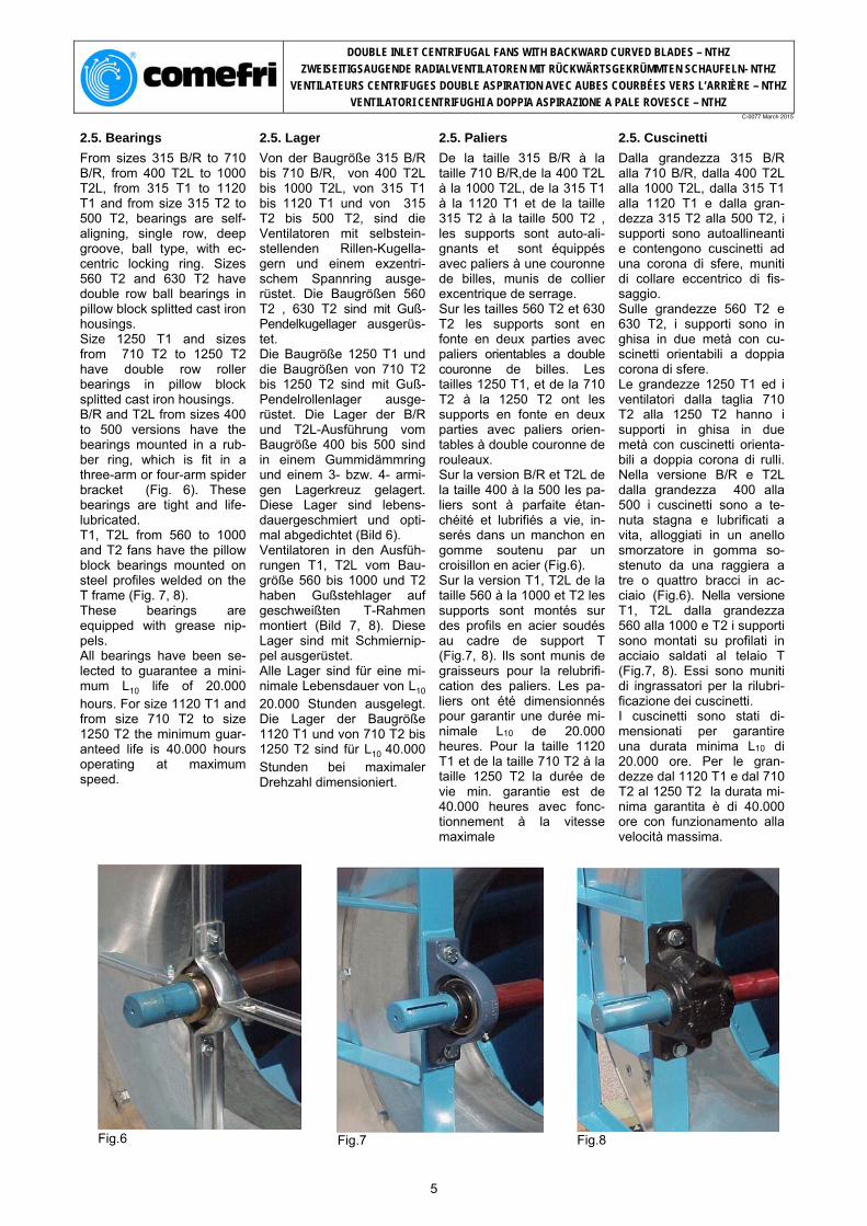
From sizes 315 B/R to 710 B/R, from 400 T2L to 1000 T2L, from 315 T1 to 1120 T1 and from size 315 T2 to 500 T2, bearings are self-aligning, single row, deep groove, ball type, with ec-centric locking ring. Sizes 560 T2 and 630 T2 have double row ball bearings in pillow block splitted cast iron housings. Size 1250 T1 and sizes from 710 T2 to 1250 T2 have double row roller bearings in pillow block splitted cast iron housings. B/R and T2L from sizes 400 to 500 versions have the bearings mounted in a rub-ber ring, which is fit in a three-arm or four-arm spider bracket (Fig. 6). These bearings are tight and life-lubricated. T1, T2L from 560 to 1000 and T2 fans have the pillow block bearings mounted on steel profiles welded on the T frame (Fig. 7, 8). These bearings are equipped with grease nip-pels. All bearings have been se-lected to guarantee a mini-mum L10 life of 20.000 hours. For size 1120 T1 and from size 710 T2 to size 1250 T2 the minimum guar-anteed life is 40.000 hours operating at maximum speed.
Von der Baugröße 315 B/R bis 710 B/R, von 400 T2L bis 1000 T2L, von 315 T1 bis 1120 T1 und von 315 T2 bis 500 T2, sind die Ventilatoren mit selbstein-stellenden Rillen-Kugella-gern und einem exzentri-schem Spannring ausge-rüstet. Die Baugrößen 560 T2 , 630 T2 sind mit Guß-Pendelkugellager ausgerüs-tet. Die Baugröße 1250 T1 und die Baugrößen von 710 T2 bis 1250 T2 sind mit Guß- Pendelrollenlager ausge-rüstet. Die Lager der B/R und T2L-Ausführung vom Baugröße 400 bis 500 sind in einem Gummidämmring und einem 3- bzw. 4- armi-gen Lagerkreuz gelagert. Diese Lager sind lebens-dauergeschmiert und opti-mal abgedichtet (Bild 6). Ventilatoren in den Ausfüh-rungen T1, T2L vom Bau-größe 560 bis 1000 und T2 haben Gußstehlager auf geschweißten T-Rahmen montiert (Bild 7, 8). Diese Lager sind mit Schmiernip-pel ausgerüstet. Alle Lager sind für eine mi-nimale Lebensdauer von L10 20.000 Stunden ausgelegt. Die Lager der Baugröße 1120 T1 und von 710 T2 bis 1250 T2 sind für L10 40.000 Stunden bei maximaler Drehzahl dimensioniert.
De la taille 315 B/R à la taille 710 B/R,de la 400 T2L à la 1000 T2L, de la 315 T1 à la 1120 T1 et de la taille 315 T2 à la taille 500 T2 , les supports sont auto-ali-gnants et sont équippés avec paliers à une couronne de billes, munis de collier excentrique de serrage. Sur les tailles 560 T2 et 630 T2 les supports sont en fonte en deux parties avec paliers orientables a double couronne de billes. Les tailles 1250 T1, et de la 710 T2 à la 1250 T2 ont les supports en fonte en deux parties avec paliers orien-tables à double couronne de rouleaux. Sur la version B/R et T2L de la taille 400 à la 500 les pa-liers sont à parfaite étan-chéité et lubrifiés a vie, in-serés dans un manchon en gomme soutenu par un croisillon en acier (Fig.6). Sur la version T1, T2L de la taille 560 à la 1000 et T2 les supports sont montés sur des profils en acier soudés au cadre de support T (Fig.7, 8). Ils sont munis de graisseurs pour la relubrifi-cation des paliers. Les pa-liers ont été dimensionnés pour garantir une durée mi-nimale L10 de 20.000 heures. Pour la taille 1120 T1 et de la taille 710 T2 à la taille 1250 T2 la durée de vie min. garantie est de 40.000 heures avec fonc-tionnement à la vitesse maximale
Dalla grandezza 315 B/R alla 710 B/R, dalla 400 T2L alla 1000 T2L, dalla 315 T1 alla 1120 T1 e dalla gran-dezza 315 T2 alla 500 T2, i supporti sono autoallineanti e contengono cuscinetti ad una corona di sfere, muniti di collare eccentrico di fis-saggio. Sulle grandezze 560 T2 e 630 T2, i supporti sono in ghisa in due metà con cu-scinetti orientabili a doppia corona di sfere. Le grandezze 1250 T1 ed i ventilatori dalla taglia 710 T2 alla 1250 T2 hanno i supporti in ghisa in due metà con cuscinetti orienta-bili a doppia corona di rulli. Nella versione B/R e T2L dalla grandezza 400 alla 500 i cuscinetti sono a te-nuta stagna e lubrificati a vita, alloggiati in un anello smorzatore in gomma so-stenuto da una raggiera a tre o quattro bracci in ac-ciaio (Fig.6). Nella versione T1, T2L dalla grandezza 560 alla 1000 e T2 i supporti sono montati su profilati in acciaio saldati al telaio T (Fig.7, 8). Essi sono muniti di ingrassatori per la rilubri-ficazione dei cuscinetti. I cuscinetti sono stati di-mensionati per garantire una durata minima L10 di 20.000 ore. Per le gran-dezze dal 1120 T1 e dal 710 T2 al 1250 T2 la durata mi-nima garantita è di 40.000 ore con funzionamento alla velocità massima.
Fig.6
Fig.7
Fig.8
5
DOUBLE INLET CENTRIFUGAL FANS WITH BACKWARD CURVED BLADES – NTHZ
ZWEISEITIGSAUGENDE RADIALVENTILATOREN MIT RÜCKWÄRTSGEKRÜMMTEN SCHAUFELN- NTHZ
VENTILATEURS CENTRIFUGES DOUBLE ASPIRATION AVEC AUBES COURBÉES VERS L’ARRIÈRE – NTHZ
VENTILATORI CENTRIFUGHI A DOPPIA ASPIRAZIONE A PALE ROVESCE – NTHZ C-0077 March 2015
2.6. Frames 2.6. Rahmen 2.6. Cadres de support 2.6. Telai
The fan must be stabilised on a base (frame or plat-form) to ensure no structural deformations caused by the tension of the belts. This concerns especially fans in discharge position 270°. Therefore we recommend the use of the R-frame exe-cution or a similar reinforced structure when the fan works at the limits of its performances. This will increase the life time of the fan.
Der Ventilator ist grundsätzlich so auf einem Grundrah-men, bzw. einer Grundplatte zu fixieren, dass keine De-formation durch den Rie-menzug entstehen kann. Wir empfehlen, bei Venti-latoren in B-Ausführung an der oberen Leistungs-grenze, die Verwendung eines R-Rahmens oder eine ähnliche Ausführung vorzu-sehen. Diese Maßnahme kann die Lebensdauer der Ventila-torkugellager deutlich erhö-hen.
Les ventilateurs doivent être fixés sur un chassis de fa-çon à éviter déformations causées par la tension des courroies. Celà est particulièrement critique avec I'orientation 270°. Nous conseillons par conséquence I'utilisation de la version avec cadre R ou d'une structure renforcée de la même façon, quand le ventilateur fonctionne à la limite de ses préstations. Ce fait augmente la durée du ventilateur.
I ventilatori devono essere fissati su di un telaio di base in modo da evitare defor-mazioni causate dal tiro cin-ghia. Questo è particolarmente critico nell'orientamento a 270°. Raccomandiamo quindi I'uso della versione con telaio R o di una strut-tura similmente rinforzata, quando il ventilatore lavora al limite delle sue presta-zioni. Questo aumenta la durata del ventilatore.
PURGE SUR VOLUTE / TAPPO DI SCARICO 28 - BEARING / LAGER / PALIER / CUSCINETTO
2 - T FRAME / “T” RAHMEN / CADRE TYPE T / TELAIO TIPO T 6 - MOTOR / MOTOR / MOTEUR / MOTORE ELETTRICO 29 - RUBBER INTERLINER / GUMMIDÄMMRING / BAGUE CAOUTCHOUC / MANICOTTO IN GOMMA
3 - INLET CONE WITH FOREFINGER / EINSTRÖMDÜSE MIT FOREFINGER / PAVILION AVEC FOREFINGER / BOCCAGLIO CON FOREFINGER 7 - MOTOR RAILS / MOTORSPANNSCHIENEN /
4 - INSPECTION DOOR / INSPEKTIONSKLAPPE / PORTE D'INSPECTION / PORTINA D'ISPEZIONE
8 - BASE FRAME / GRUNDRAHMEN / CHASSIS / BASAMENTO 31 - MOTOR BASE PLATE / MOTORSPANNSCHLITTEN / SUPPORT MOTEUR / BASE MOTORE
6
DOUBLE INLET CENTRIFUGAL FANS WITH BACKWARD CURVED BLADES – NTHZ
ZWEISEITIGSAUGENDE RADIALVENTILATOREN MIT RÜCKWÄRTSGEKRÜMMTEN SCHAUFELN- NTHZ
VENTILATEURS CENTRIFUGES DOUBLE ASPIRATION AVEC AUBES COURBÉES VERS L’ARRIÈRE – NTHZ
VENTILATORI CENTRIFUGHI A DOPPIA ASPIRAZIONE A PALE ROVESCE – NTHZ C-0077 March 2015
4. Fan performances 4. Ventilator Leistungskurven
4. Prestations 4. Prestazioni
4.1. Performance data 4.1. Leistungsdaten 4.1. Diagrammes 4.1. Diagrammi
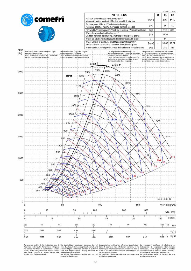
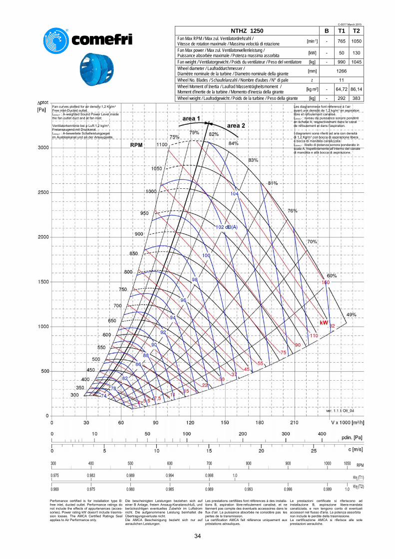
Comefri’s laboratory has measured the data included in the performance chart section with modern, state-of-the-art testing instru-ments. The performances were measured for an installation type B, i.e. free inlet and ducted outlet configuration All curves to a density of = 1,2 kg/m3 Outlet velocity “c” and dy-namic pressure “pdyn“refer to the flange cross section area at the fan outlet Performance data accord-ing to DIN 24166 Class 1. Performance test rig according to
Im Comefri-Labor wurden die Leistungsdaten mit mo-dernster Technik aufge-nommen. Die Ermittlung der Kennli-nien erfolgte mit druckseiti-gem Kanalanschluss frei-ansaugend Alle Leistungsdiagramme beziehen sich auf eine Luft-dichte von = 1,2 kg/m3 Die Ausblasgeschwindigkeit “c“ und der dynamische Druck “pdyn“beziehen sich auf den Ausblasflansch-querschnitt Ventilatoredaten nach DIN 24166 in Genauigkeits-klasse 1. Prüfstandaufbau nach
Les données représentées sur les courbes de sélection ont été élaborées avec des mésure effectuées selon les plus modernes méthodologies dans le Laboratoire Comefri. Les préstations font réfe-rence à une installation de type B, avec aspirations libres et refoulement canalisé Toutes les courbes font reference a une densite d'air de = 1,2 kg/m3 La vitesse de sortie “c” et la pression dynamique “pdyn” font réference à la section de la bride du refoulement Courbeses selon les normes DIN 24166 Classe 1. Schéma banc d'essai selon les normes
I dati riportati nelle curve di selezione sono stati ricavati da misure eseguite con le più moderne metodologie nel laboratorio Comefri. Le prestazioni sono riferite ad un'installazione di tipo B, con bocche aspiranti libere e bocca di mandata canalizzata Tutte le curve sono riferite ad una densità dell'aria di = 1,2 kg/m3 La velocità di uscita “c” e la pressione dinamica “pdyn” sono riferite alla sezione della flangia della bocca premente Curve caratteristiche se-condo le norme DIN 24166, Classe 1. Schema banco prova secondo le norme
DIN 24163 /BS 848 Part 1 / ISO 5801 / AMCA 210 - fig.14.
1. Fan 2. Outlet duct 3. Electric motor drive 4. Torquemeter 5. Tachometer 6. Differential pressure gauge 7. Temperature probe 8. Test chamber 9. Flow straightener
1. Ventilatore 2. Canale di mandata 3. Motore elettrico 4. Torsiometro 5. Tachimetro 6. Manometro differenziale 7. Sonda termometrica 8. Camera di prova 9. Raddrizzatore di flusso
10. Serranda di regolazione 11. Boccaglio normalizzato
The performance curves in-clude the following information:
Die Leistungskurven zeigen folgende Informationen:
Les diagrammes compren-nent les données suivantes:
I diagrammi comprendono i dati seguenti:
Total pressure Gesamtdruckdifferenz Pression totale Pressione totale ptot [ Pa ]
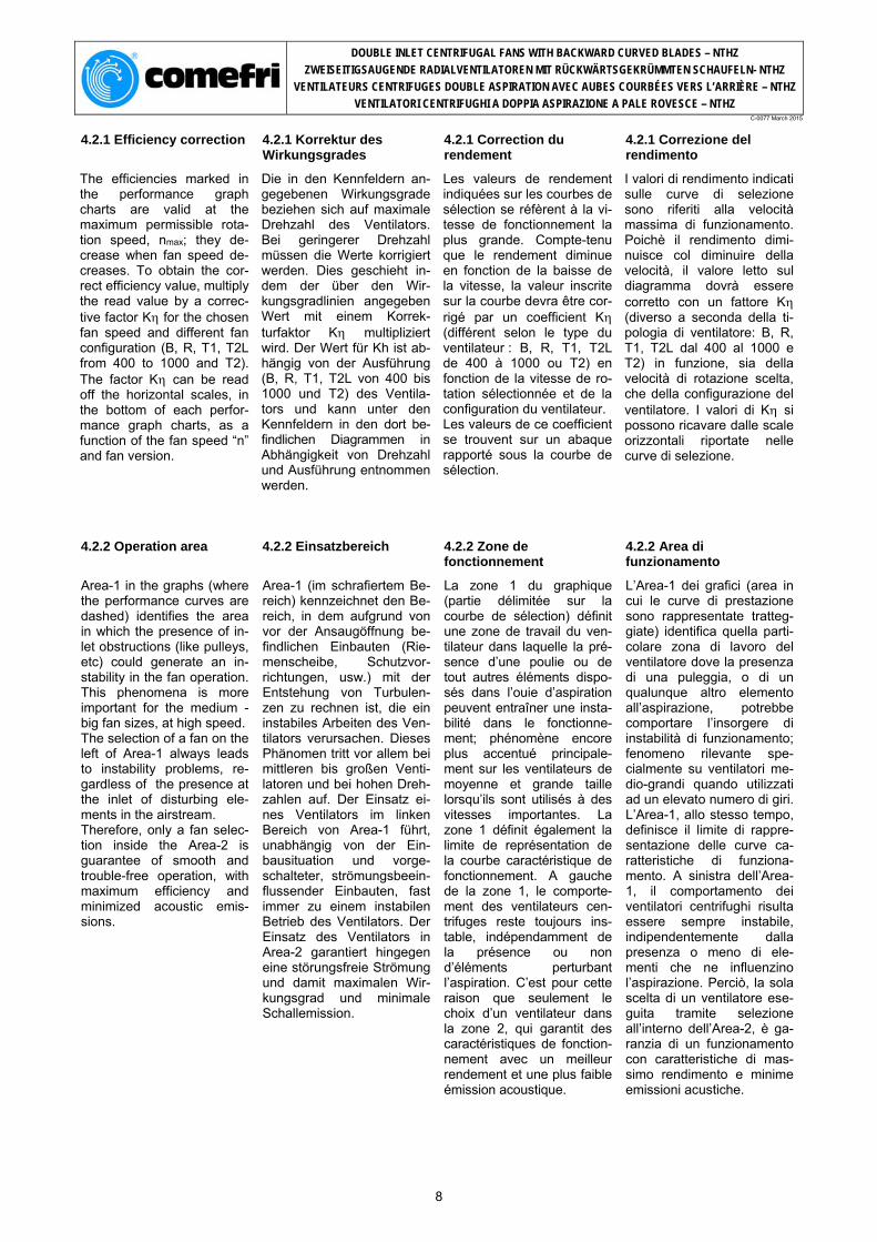
The efficiencies marked in the performance graph charts are valid at the maximum permissible rota-tion speed, nmax; they de-crease when fan speed de-creases. To obtain the cor-rect efficiency value, multiply the read value by a correc-tive factor K for the chosen fan speed and different fan configuration (B, R, T1, T2L from 400 to 1000 and T2). The factor K can be read off the horizontal scales, in the bottom of each perfor-mance graph charts, as a function of the fan speed “n” and fan version.
Die in den Kennfeldern an-gegebenen Wirkungsgrade beziehen sich auf maximale Drehzahl des Ventilators. Bei geringerer Drehzahl müssen die Werte korrigiert werden. Dies geschieht in-dem der über den Wir-kungsgradlinien angegeben Wert mit einem Korrek-turfaktor K multipliziert wird. Der Wert für Kh ist ab-hängig von der Ausführung (B, R, T1, T2L von 400 bis 1000 und T2) des Ventila-tors und kann unter den Kennfeldern in den dort be-findlichen Diagrammen in Abhängigkeit von Drehzahl und Ausführung entnommen werden.
Les valeurs de rendement indiquées sur les courbes de sélection se réfèrent à la vi-tesse de fonctionnement la plus grande. Compte-tenu que le rendement diminue en fonction de la baisse de la vitesse, la valeur inscrite sur la courbe devra être cor-rigé par un coefficient K (différent selon le type du ventilateur : B, R, T1, T2L de 400 à 1000 ou T2) en fonction de la vitesse de ro-tation sélectionnée et de la configuration du ventilateur. Les valeurs de ce coefficient se trouvent sur un abaque rapporté sous la courbe de sélection.
I valori di rendimento indicati sulle curve di selezione sono riferiti alla velocità massima di funzionamento. Poichè il rendimento dimi-nuisce col diminuire della velocità, il valore letto sul diagramma dovrà essere corretto con un fattore K (diverso a seconda della ti-pologia di ventilatore: B, R, T1, T2L dal 400 al 1000 e T2) in funzione, sia della velocità di rotazione scelta, che della configurazione del ventilatore. I valori di K si possono ricavare dalle scale orizzontali riportate nelle curve di selezione.
4.2.2 Operation area 4.2.2 Einsatzbereich 4.2.2 Zone de fonctionnement
4.2.2 Area di funzionamento
Area-1 in the graphs (where the performance curves are dashed) identifies the area in which the presence of in-let obstructions (like pulleys, etc) could generate an in-stability in the fan operation. This phenomena is more important for the medium - big fan sizes, at high speed. The selection of a fan on the left of Area-1 always leads to instability problems, re-gardless of the presence at the inlet of disturbing ele-ments in the airstream. Therefore, only a fan selec-tion inside the Area-2 is guarantee of smooth and trouble-free operation, with maximum efficiency and minimized acoustic emis-sions.
Area-1 (im schrafiertem Be-reich) kennzeichnet den Be-reich, in dem aufgrund von vor der Ansaugöffnung be-findlichen Einbauten (Rie-menscheibe, Schutzvor-richtungen, usw.) mit der Entstehung von Turbulen-zen zu rechnen ist, die ein instabiles Arbeiten des Ven-tilators verursachen. Dieses Phänomen tritt vor allem bei mittleren bis großen Venti-latoren und bei hohen Dreh-zahlen auf. Der Einsatz ei-nes Ventilators im linken Bereich von Area-1 führt, unabhängig von der Ein-bausituation und vorge-schalteter, strömungsbeein-flussender Einbauten, fast immer zu einem instabilen Betrieb des Ventilators. Der Einsatz des Ventilators in Area-2 garantiert hingegen eine störungsfreie Strömung und damit maximalen Wir-kungsgrad und minimale Schallemission.
La zone 1 du graphique (partie délimitée sur la courbe de sélection) définit une zone de travail du ven-tilateur dans laquelle la pré-sence d’une poulie ou de tout autres éléments dispo-sés dans l’ouie d’aspiration peuvent entraîner une insta-bilité dans le fonctionne-ment; phénomène encore plus accentué principale-ment sur les ventilateurs de moyenne et grande taille lorsqu’ils sont utilisés à des vitesses importantes. La zone 1 définit également la limite de représentation de la courbe caractéristique de fonctionnement. A gauche de la zone 1, le comporte-ment des ventilateurs cen-trifuges reste toujours ins-table, indépendamment de la présence ou non d’éléments perturbant l’aspiration. C’est pour cette raison que seulement le choix d’un ventilateur dans la zone 2, qui garantit des caractéristiques de fonction-nement avec un meilleur rendement et une plus faible émission acoustique.
L’Area-1 dei grafici (area in cui le curve di prestazione sono rappresentate tratteg-giate) identifica quella parti-colare zona di lavoro del ventilatore dove la presenza di una puleggia, o di un qualunque altro elemento all’aspirazione, potrebbe comportare l’insorgere di instabilità di funzionamento; fenomeno rilevante spe-cialmente su ventilatori me-dio-grandi quando utilizzati ad un elevato numero di giri. L’Area-1, allo stesso tempo, definisce il limite di rappre-sentazione delle curve ca-ratteristiche di funziona-mento. A sinistra dell’Area-1, il comportamento dei ventilatori centrifughi risulta essere sempre instabile, indipendentemente dalla presenza o meno di ele-menti che ne influenzino l’aspirazione. Perciò, la sola scelta di un ventilatore ese-guita tramite selezione all’interno dell’Area-2, è ga-ranzia di un funzionamento con caratteristiche di mas-simo rendimento e minime emissioni acustiche.
8
DOUBLE INLET CENTRIFUGAL FANS WITH BACKWARD CURVED BLADES – NTHZ
ZWEISEITIGSAUGENDE RADIALVENTILATOREN MIT RÜCKWÄRTSGEKRÜMMTEN SCHAUFELN- NTHZ
VENTILATEURS CENTRIFUGES DOUBLE ASPIRATION AVEC AUBES COURBÉES VERS L’ARRIÈRE – NTHZ
VENTILATORI CENTRIFUGHI A DOPPIA ASPIRAZIONE A PALE ROVESCE – NTHZ C-0077 March 2015
4.3. Motor selection 4.3. Motorauslegung 4.3. Selection du moteur 4.3. Scelta del motore
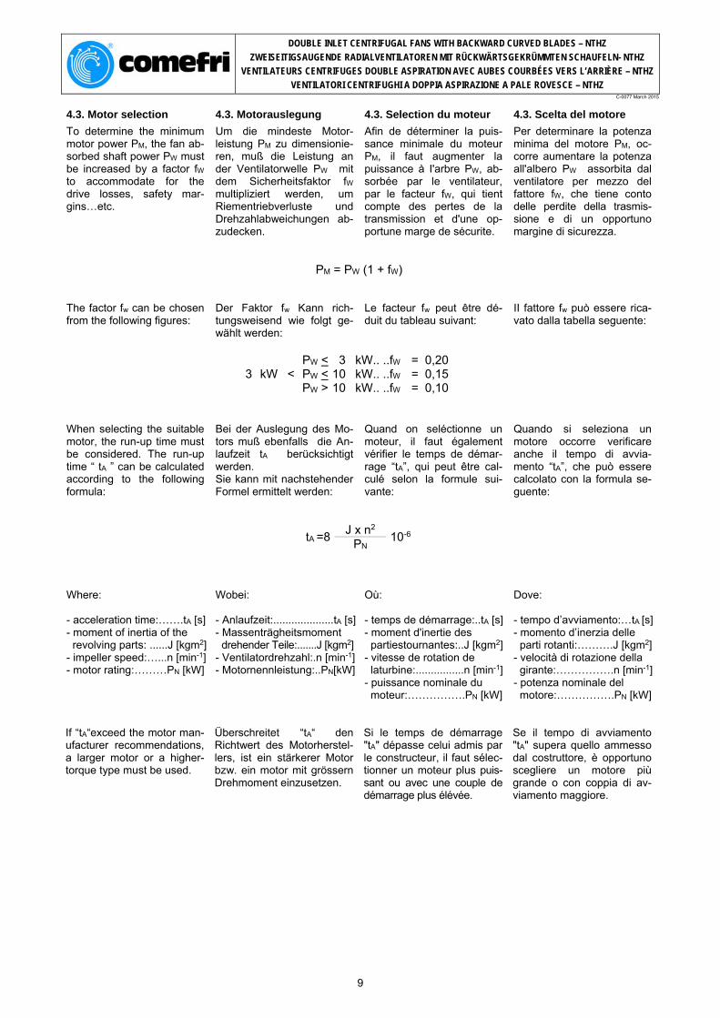
To determine the minimum motor power PM, the fan ab-sorbed shaft power PW must be increased by a factor fW to accommodate for the drive losses, safety mar-gins…etc.
Um die mindeste Motor-leistung PM zu dimensionie-ren, muß die Leistung an der Ventilatorwelle PW mit dem Sicherheitsfaktor fW multipliziert werden, um Riementriebverluste und Drehzahlabweichungen ab-zudecken.
Afin de déterminer la puis-sance minimale du moteur PM, il faut augmenter la puissance à I'arbre PW, ab-sorbée par le ventilateur, par le facteur fW, qui tient compte des pertes de la transmission et d'une op-portune marge de sécurite.
Per determinare la potenza minima del motore PM, oc-corre aumentare la potenza all'albero PW assorbita dal ventilatore per mezzo del fattore fW, che tiene conto delle perdite della trasmis-sione e di un opportuno margine di sicurezza.
PM = PW (1 + fW)
The factor fw can be chosen from the following figures:
Der Faktor fw Kann rich-tungsweisend wie folgt ge-wählt werden:
Le facteur fw peut être dé-duit du tableau suivant:
II fattore fw può essere rica-vato dalla tabella seguente:
3
kW
<
PW <PW <PW >
31010
kW..kW..kW..
..fW
..fW
..fW
===
0,20 0,15 0,10
When selecting the suitable motor, the run-up time must be considered. The run-up time “ tA ” can be calculated according to the following formula:
Bei der Auslegung des Mo-tors muß ebenfalls die An-laufzeit tA berücksichtigt werden. Sie kann mit nachstehender Formel ermittelt werden:
Quand on seléctionne un moteur, il faut également vérifier le temps de démar-rage “tA”, qui peut être cal-culé selon la formule sui-vante:
Quando si seleziona un motore occorre verificare anche il tempo di avvia-mento “tA”, che può essere calcolato con la formula se-guente:
tA =8 J x n2
10-6 PN
Where: - acceleration time:…….tA [s] - moment of inertia of the revolving parts: ......J [kgm2] - impeller speed:…...n [min-1] - motor rating:………PN [kW]
Où: - temps de démarrage:..tA [s] - moment d'inertie des partiestournantes:..J [kgm2] - vitesse de rotation de laturbine:................n [min-1] - puissance nominale du moteur:…………….PN [kW]
Dove: - tempo d’avviamento:…tA [s]- momento d’inerzia delle parti rotanti:……….J [kgm2] - velocità di rotazione della girante:…………….n [min-1]- potenza nominale del motore:…………….PN [kW]
If “tA“exceed the motor man-ufacturer recommendations, a larger motor or a higher-torque type must be used.
Überschreitet “tA“ den Richtwert des Motorherstel-lers, ist ein stärkerer Motor bzw. ein motor mit grössern Drehmoment einzusetzen.
Si le temps de démarrage "tA" dépasse celui admis par le constructeur, il faut sélec-tionner un moteur plus puis-sant ou avec une couple de démarrage plus élévée.
Se il tempo di avviamento "tA" supera quello ammesso dal costruttore, è opportuno scegliere un motore più grande o con coppia di av-viamento maggiore.
9
DOUBLE INLET CENTRIFUGAL FANS WITH BACKWARD CURVED BLADES – NTHZ
ZWEISEITIGSAUGENDE RADIALVENTILATOREN MIT RÜCKWÄRTSGEKRÜMMTEN SCHAUFELN- NTHZ
VENTILATEURS CENTRIFUGES DOUBLE ASPIRATION AVEC AUBES COURBÉES VERS L’ARRIÈRE – NTHZ
VENTILATORI CENTRIFUGHI A DOPPIA ASPIRAZIONE A PALE ROVESCE – NTHZ C-0077 March 2015
4.4. Correction of performance data referred to free outlet (Installation type A)
4.4. Korrektur der Leistungsdaten bei Anordnung-A (Installationstyp-A)
4.4. Correction des prestations dans le cas de refoulement libre (installation type A)
4.4. Correzione delle prestazioni nel caso di bocca premente libera (Installazione di tipo A)
As all data present in the fan performance charts refer to the free inlet-ducted outlet configuration, correction to those data must be applied when a free outlet installa-tion type A is requested. The static pressure in free inlet-ducted outlet condition is:
Die in den Leistungskennli-nien angegebenen Daten beziehen sich auf die An-ordnung freiansaugend mit druckseitigem Kanalan-schluss. Bei freiausblasen-der Installationtyp-A müßt die stat. Druck korrigiert werden. Der statische Druck, frei-ansaugend bei druckseiti-gem Kanalanschluss, wird wie folgt berechnet:
Tous les diagrammes de sélection font réference à la configuration avec aspiration libre – refoulement canalisé; afin d'avoir la pression sta-tique, quand le refoulement est libre (installation type A), il faut introduire une correc-tion, selon la suivante pro-cédure: La pression statique avec aspiration libre-refoulement canalisé est:
Tutti i diagrammi di sele-zione sono riferiti alla confi-gurazione con bocca aspi-rante libera–bocca premente canalizzata; per conoscere la pressione statica con bocca premente libera (in-stallazione tipo A), occorre introdurre una correzione, secondo la procedura se-guente: La pressione statica con bocca aspirante libera-bocca premente canalizzata è:
pfst = ptot - pdyn
In free discharge condition the static pressure pfa, for a given fan speed, can be ob-tained as:
Bei freiausblasendem Ven-tilator wird der statische Druck pfa wie folgt berechnet:
La pression statique avec refoulement libre est:
La pressione statica con bocca premente libera è:
pfa = ptot - pdyn-kfa x pdyn = pfst - kfa x pdyn
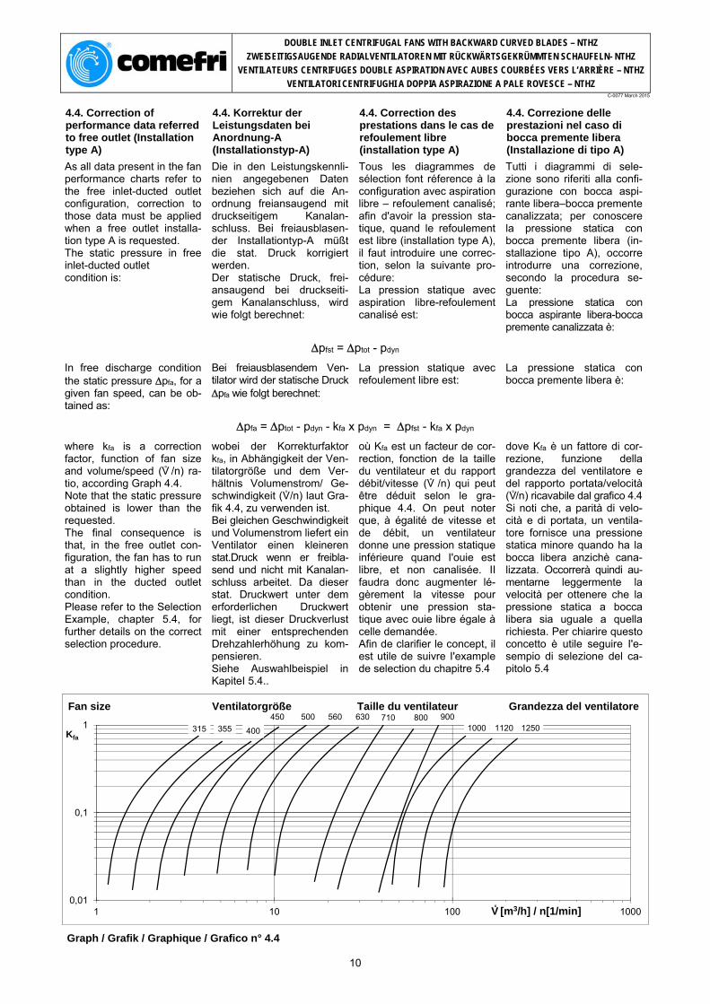
where kfa is a correction factor, function of fan size and volume/speed (V° /n) ra-tio, according Graph 4.4. Note that the static pressure obtained is lower than the requested. The final consequence is that, in the free outlet con-figuration, the fan has to run at a slightly higher speed than in the ducted outlet condition. Please refer to the Selection Example, chapter 5.4, for further details on the correct selection procedure.
wobei der Korrekturfaktor kfa, in Abhängigkeit der Ven-tilatorgröße und dem Ver-hältnis Volumenstrom/ Ge-schwindigkeit (V° /n) laut Gra-fik 4.4, zu verwenden ist. Bei gleichen Geschwindigkeit und Volumenstrom liefert ein Ventilator einen kleineren stat.Druck wenn er freibla-send und nicht mit Kanalan-schluss arbeitet. Da dieser stat. Druckwert unter dem erforderlichen Druckwert liegt, ist dieser Druckverlust mit einer entsprechenden Drehzahlerhöhung zu kom-pensieren. Siehe Auswahlbeispiel in KapiteI 5.4..
où Kfa est un facteur de cor-rection, fonction de la taille du ventilateur et du rapport débit/vitesse (V° /n) qui peut être déduit selon le gra-phique 4.4. On peut noter que, à égalité de vitesse et de débit, un ventilateur donne une pression statique inférieure quand I'ouie est libre, et non canalisée. II faudra donc augmenter lé-gèrement la vitesse pour obtenir une pression sta-tique avec ouie libre égale à celle demandée. Afin de clarifier le concept, il est utile de suivre I'example de selection du chapitre 5.4
dove Kfa è un fattore di cor-rezione, funzione della grandezza del ventilatore e del rapporto portata/velocità (V° /n) ricavabile dal grafico 4.4 Si noti che, a parità di velo-cità e di portata, un ventila-tore fornisce una pressione statica minore quando ha la bocca libera anzichè cana-lizzata. Occorrerà quindi au-mentarne leggermente la velocità per ottenere che la pressione statica a bocca libera sia uguale a quella richiesta. Per chiarire questo concetto è utile seguire I'e-sempio di selezione del ca-pitolo 5.4
Graph / Grafik / Graphique / Grafico n° 4.4
10
0,01
0,1
1
1 10 100 1000
Kfa
V[m3/h]/n[1/min]
125011201000900800710630560500450
400355315
Fan size Ventilatorgröße Taille du ventilateur Grandezza del ventilatore
V° [m3/h] / n[1/min]
DOUBLE INLET CENTRIFUGAL FANS WITH BACKWARD CURVED BLADES – NTHZ
ZWEISEITIGSAUGENDE RADIALVENTILATOREN MIT RÜCKWÄRTSGEKRÜMMTEN SCHAUFELN- NTHZ
VENTILATEURS CENTRIFUGES DOUBLE ASPIRATION AVEC AUBES COURBÉES VERS L’ARRIÈRE – NTHZ
VENTILATORI CENTRIFUGHI A DOPPIA ASPIRAZIONE A PALE ROVESCE – NTHZ C-0077 March 2015
4.5.Temperature and altitude correction factors
4.5. Korrekturfaktoren für Temperatur und Aufstellhöhe
4.5. Correction pour temperature et altitude
4.5. Correzione per temperatura e altitudine
The performance charts re-fer to the standard air condi-tion, i.e. 20°C temperature and sea level altitude, with density = 1,2 kg/m3. In different operating condi-tions the data must be cor-rected to consider the change in air density.
Die Ventilatorkennlinien be-ziehen sich auf = 1,2 kg/m3, bei einer Temperatur von 20°C und einer Höhe von 0 m über dem Meeresspiegel. Unter abweichenden Be-triebsbedingungen muss die Dichte des Fördermediums korrigiert werden.
Les diagrammes de sélec-tion font réference à une temperature de 20°C au ni-veau de la mer, ayant den-sité = 1,2 kg/m3. Si les conditions de tempé-rature et d'altitude varient, la densité de I'air se modifie aussi, par conséquence quelques données deduites des diagrammes doivent être corrigées.
I diagrammi di scelta sono riferiti ad aria a 20°C a livello del mare, avente densità = 1,2 kg/m3. Variando le condizioni di temperatura e di altitudine,varia la densità dell'aria, quindi alcuni dati ricavati dai diagrammi devono essere corretti.
a) Volume and efficiency do not vary, while pressure and power vary directly as the ratio of the air density. Given K as the ratio be-tween actual density and 1,2 we have:
a) Volumenstrom und Wir-kungsgrad bleiben unverän-dert; hingegen verändert sich die Druckerhöhung proportional mit der Dichte des Fördermediums. Vorgegeben Kp als Verhält-nis zwischen aktueller Dichte und 1,2, erhält man:
a) Débit et rendement res-tent invariés, tandis que pression et puissance va-rient de façon directement proportionelle à la densité. Donné K le rapport entre la densité actuelle et 1,2 on a:
a) Portata e rendimento re-stano invariati, mentre pres-sione e potenza variano in modo direttamente propor-zionale alla densità. Posto K il rapporto tra la densità attuale e 1,2 si ha:
ptot2 = ptot1 x K
b) and the power b) und die aufgenommene Leistung
b) pour la puissance: b) per la potenza:
Pw2 = Pw1 x K
The Graph 4.5 contains air density ratios Kfor tem-peratures from -20°C to +80°C and eleva-tions up to 2000 meters above sea level (Kfor t = 20°C, elevation = 0 m).
Die folgende Grafik 4.5 zeigt die Luftdichte K für Tempe-raturen von -20°C bis +80°C, bei Höhen bis 2000 Meter über dem Meeresspiegel an (Kfür t = 20°C, Höhe über dem Meeresspiegel = 0 m).
Le graphique 4.5 comprend les valeurs K pour tempé-ratures comprises entre -20°C et +80°C et pour alti-tudes comprises entre 0 m (niveau de la mer) et 2000 m sur le niveau de la mer (K = 1 pour t = 20°C et 0 m s.n.m.).
II grafico 4.5 contiene i valori K per temperature com-prese tra -20°C e +80°C e per altitudini comprese tra 0 m (livello del mare) e 2000 m sopra il livello del mare (K = 1 per t = 20°C e 0 m s.l.m.).
Graph / Grafik / Graphique / Grafico n° 4.5
11
0,60
0,70
0,80
0,90
1,00
1,10
1,20
-20 -10 0 10 20 30 40 50 60 70 80
K
t [°C]
Höhe (Meter über Meerhöhe)Elevation [meters Above Sea Level]
0
20001500
1000750
500250
Elevation (meters Above Sea Level) Höhe (Meter über Meerhöhe)
Altitude (mètres sur le niveau de la mer) Altitudine (metri sul livello del mare)
DOUBLE INLET CENTRIFUGAL FANS WITH BACKWARD CURVED BLADES – NTHZ
ZWEISEITIGSAUGENDE RADIALVENTILATOREN MIT RÜCKWÄRTSGEKRÜMMTEN SCHAUFELN- NTHZ
VENTILATEURS CENTRIFUGES DOUBLE ASPIRATION AVEC AUBES COURBÉES VERS L’ARRIÈRE – NTHZ
VENTILATORI CENTRIFUGHI A DOPPIA ASPIRAZIONE A PALE ROVESCE – NTHZ C-0077 March 2015
5. Sound levels 5. Schalleistungsangaben
The measurements of noise levels are taken according to ISO, DIN, AMCA and BS Standards using a real-time fre-quency analyser. The sound power level LwA, referred to Wo=10-12 watt, required for calculation and design of sound absorbing units, is marked on the performance charts. Sound data are determined according to DIN 45635-38, BS EN ISO 5136 and ANSI-AMCA 330 – In-duct method. The accuracy class, as defined by DIN 24166, Class 1, i.e. the permissible deviation on the read value is equal to +3 dBA
Der Geräuschpegel wurde entsprechend ISO, DIN, AMCA und BS Standard mit Echtzeitfrequenzanalysator gemes-sen. Der für die Berechnung und Auslegung der Schall-dämmelemente erforderliche Schalleistungspegel LwA, be-zogen auf Wo=10-12 Watt, ist als Parameter im Kennfeld eingetragen. Die Geräuschmessung und die diesbezügliche Auswertung erfolgte nach DIN 45635-38, BS EN ISO 5136 und ANSI-AMCA 330 - Kanalverfahren. Die Katalogwerte werden nach DIN 24 166, in Genauigkeitsklasse 1 angegeben, d.h. die zulässige Abweichung kann bis +3 dBA betragen.
Symbols and Formulae: Symbole und Formeln:
LwA4 A-weighted Total Sound Power Level inside the outlet duct ………………………………...…..…………. [dBA]
LwA4 A-bewerteter Gesamtschalleistungspegel im Druckkanal ...........…..…………………..…........... [dBA]
LwA7 A-weighted Total Sound Power Level at the fan inlet, with ducted outlet ………………………….………….… [dBA]
LwA7 A-bewerteter Gesamtschalleistungspegel in der Ansaugöffnung ......................................................... [dBA]
Lw4 Total Sound Power Level inside the outlet duct …...... [dB] Lw4 Gesamtschalleistungspegel im Druckkanal .............. [dB] Lwoct4 Sound Power Level inside the outlet duct at a
specific Octave Band .…………..……………………… [dB] Lwoct4 Schalleistungspegel im Druckkanal bei einer
bestimmten Oktavmittenfrequenz ............................. [dB] LwoctA4 A-weightedSound Power Level inside the outlet duct
at a specific Octave Band ……………………………... [dBA]LwoctA4 A-bewerteter Schalleistungspegel im Druckkanal bei
einer bestimmten Oktavmittenfrequenz .................... [dBA]fm Octave Band Mid-Frequency ..……………………… [Hz] fm Oktavmittenfrequenz ................................................. [Hz] Lwoct4 Difference between Sound Power Level inside the
outlet duct at a specific Octave Band, Lwoct4 and A-weighted Total Sound Power Level inside the outlet duct, LwA4 …………………….……………….…... [dB]
Lwoct4 Differenz zwischen Schalleistungspegel bei einer bestimmten Oktavmittenfrequenz Lwoct4 und dem A-bewerteten Gesamtschalleistungspegel LwA4 ........
[dB]
Lw4 Difference between the Total Sound Power Level inside the outlet duct, Lw4 and the A-weighted Total Sound Power Level inside the outlet duct, LwA4 …..….
[dB]
Lw4 Differenz zwischen den Gesamtschalleistungspegel Lw4 und dem Bewerteten Schalleistungspegel LwA4 .. [dB]
Lw6 Total Sound Power Level at the free outlet ….….…… [dB] Lw6 Gesamtschalleistungspegel – freiausblasend ........... [dB] Lwcorr Free outlet factor ………………………………………. [dB] Lwcorr Korrekturfaktor beim freien Ausblas ......................... [dB] LwoctA6 A-weighted Sound Power Level at a specific Octave
Band at the free outlet …………………………………
[dBA] LwoctA6 A-bewerteter Schalleistungspegel am freien Ansaug
Kanalblasend bei einer bestimmten Oktavmittenfrequenz ................................................ [dBA]
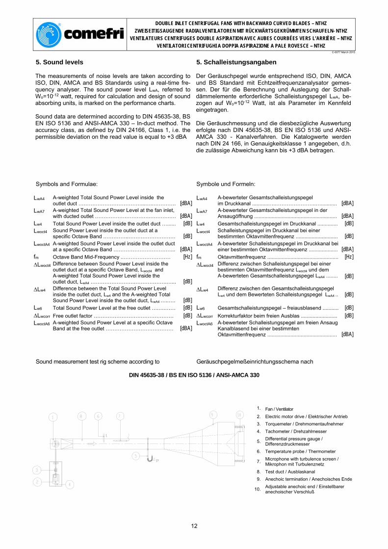
Sound measurement test rig scheme according to Geräuschpegelmeßeinrichtungsschema nach
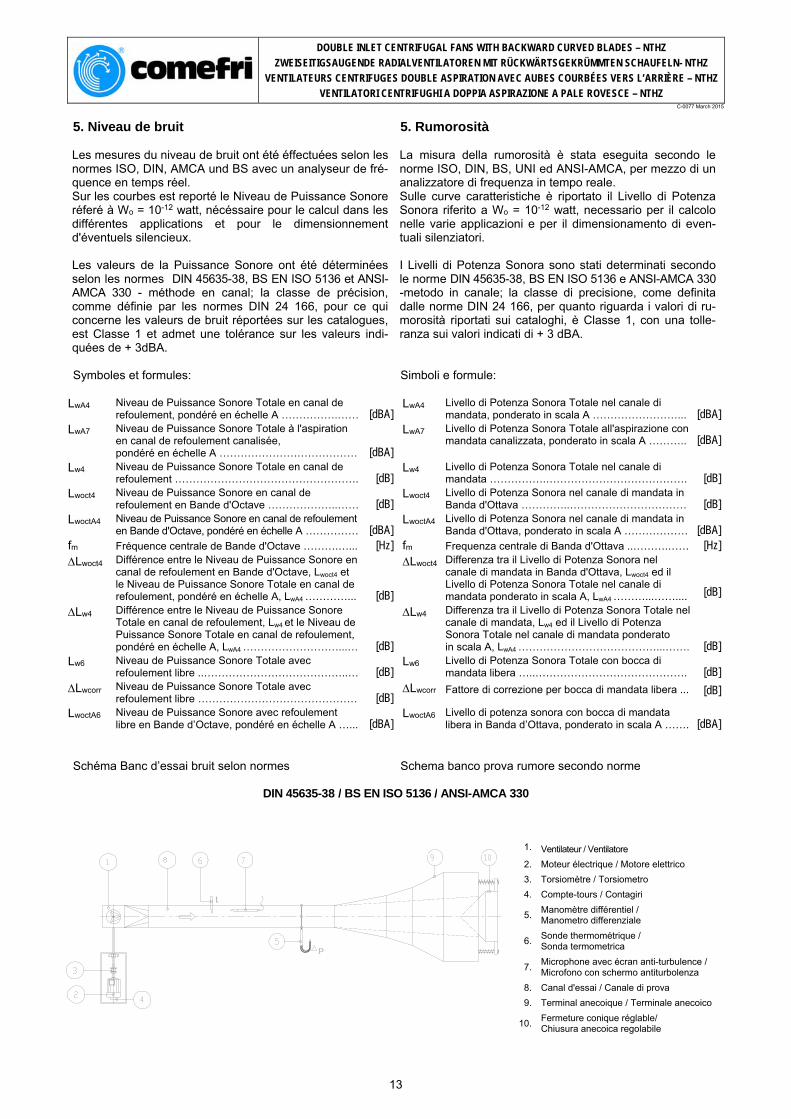
DIN 45635-38 / BS EN ISO 5136 / ANSI-AMCA 330
1. Fan / Ventilator
2. Electric motor drive / Elektrischer Antrieb 3. Torquemeter / Drehmomentaufnehmer 4. Tachometer / Drehzahlmesser
7.Microphone with turbulence screen / Mikrophon mit Turbulenznetz
8. Test duct / Ausblaskanal 9. Anechoic termination / Anechoisches Ende
10.Adjustable anechoic end / Einstellbarer anechoischer Verschluß
12
DOUBLE INLET CENTRIFUGAL FANS WITH BACKWARD CURVED BLADES – NTHZ
ZWEISEITIGSAUGENDE RADIALVENTILATOREN MIT RÜCKWÄRTSGEKRÜMMTEN SCHAUFELN- NTHZ
VENTILATEURS CENTRIFUGES DOUBLE ASPIRATION AVEC AUBES COURBÉES VERS L’ARRIÈRE – NTHZ
VENTILATORI CENTRIFUGHI A DOPPIA ASPIRAZIONE A PALE ROVESCE – NTHZ C-0077 March 2015
5. Niveau de bruit 5. Rumorosità
Les mesures du niveau de bruit ont été éffectuées selon les normes ISO, DIN, AMCA und BS avec un analyseur de fré-quence en temps réel. Sur les courbes est reporté le Niveau de Puissance Sonore réferé à Wo = 10-12 watt, nécéssaire pour le calcul dans les différentes applications et pour le dimensionnement d'éventuels silencieux. Les valeurs de la Puissance Sonore ont été déterminées selon les normes DIN 45635-38, BS EN ISO 5136 et ANSI-AMCA 330 - méthode en canal; la classe de précision, comme définie par les normes DIN 24 166, pour ce qui concerne les valeurs de bruit réportées sur les catalogues, est Classe 1 et admet une tolérance sur les valeurs indi-quées de + 3dBA.
La misura della rumorosità è stata eseguita secondo le norme ISO, DIN, BS, UNI ed ANSI-AMCA, per mezzo di un analizzatore di frequenza in tempo reale. Sulle curve caratteristiche è riportato il Livello di Potenza Sonora riferito a Wo = 10-12 watt, necessario per il calcolo nelle varie applicazioni e per il dimensionamento di even-tuali silenziatori. I Livelli di Potenza Sonora sono stati determinati secondo le norme DIN 45635-38, BS EN ISO 5136 e ANSI-AMCA 330 -metodo in canale; la classe di precisione, come definita dalle norme DIN 24 166, per quanto riguarda i valori di ru-morosità riportati sui cataloghi, è Classe 1, con una tolle-ranza sui valori indicati di + 3 dBA.
Symboles et formules: Simboli e formule:
LwA4 Niveau de Puissance Sonore Totale en canal de
refoulement, pondéré en échelle A …………….…… [dBA] LwA4 Livello di Potenza Sonora Totale nel canale di
mandata, ponderato in scala A ……………………... [dBA] LwA7 Niveau de Puissance Sonore Totale à l'aspiration
en canal de refoulement canalisée, pondéré en échelle A ………………………………… [dBA]
LwA7 Livello di Potenza Sonora Totale all'aspirazione con mandata canalizzata, ponderato in scala A ………..
[dBA]
Lw4 Niveau de Puissance Sonore Totale en canal de refoulement ……………………………………………. [dB]
Lw4 Livello di Potenza Sonora Totale nel canale di mandata …………….…………………………………. [dB]
Lwoct4 Niveau de Puissance Sonore en canal de refoulement en Bande d'Octave ………………..…… [dB]
Lwoct4 Livello di Potenza Sonora nel canale di mandata in Banda d'Ottava …………..…………………………… [dB]
LwoctA4 Niveau de Puissance Sonore en canal de refoulement en Bande d'Octave, pondéré en échelle A …………… [dBA]
LwoctA4 Livello di Potenza Sonora nel canale di mandata in Banda d'Ottava, ponderato in scala A ……………… [dBA]
fm Fréquence centrale de Bande d'Octave ……….…... [Hz] fm Frequenza centrale di Banda d'Ottava ..……….…… [Hz] Lwoct4 Différence entre le Niveau de Puissance Sonore en
canal de refoulement en Bande d'Octave, Lwoct4 et le Niveau de Puissance Sonore Totale en canal de refoulement, pondéré en échelle A, LwA4 …………...
[dB]
Lwoct4 Differenza tra il Livello di Potenza Sonora nel canale di mandata in Banda d'Ottava, Lwoct4 ed il Livello di Potenza Sonora Totale nel canale di mandata ponderato in scala A, LwA4 ………...……....
[dB]
Lw4 Différence entre le Niveau de Puissance Sonore Totale en canal de refoulement, Lw4 et le Niveau de Puissance Sonore Totale en canal de refoulement, pondéré en échelle A, LwA4 ………………………...…
[dB]
Lw4 Differenza tra il Livello di Potenza Sonora Totale nel canale di mandata, Lw4 ed il Livello di Potenza Sonora Totale nel canale di mandata ponderato in scala A, LwA4 …………………………………...…….
[dB]
Lw6 Niveau de Puissance Sonore Totale avec refoulement libre ..…………………………………..… [dB]
Lw6 Livello di Potenza Sonora Totale con bocca di mandata libera …..……………………………………. [dB]
Lwcorr Niveau de Puissance Sonore Totale avec refoulement libre ……………………………………… [dB]
Lwcorr
Fattore di correzione per bocca di mandata libera ...
[dB]
LwoctA6 Niveau de Puissance Sonore avec refoulement libre en Bande d’Octave, pondéré en échelle A …... [dBA]
LwoctA6 Livello di potenza sonora con bocca di mandata libera in Banda d’Ottava, ponderato in scala A ……. [dBA]
Schéma Banc d’essai bruit selon normes Schema banco prova rumore secondo norme
DOUBLE INLET CENTRIFUGAL FANS WITH BACKWARD CURVED BLADES – NTHZ
ZWEISEITIGSAUGENDE RADIALVENTILATOREN MIT RÜCKWÄRTSGEKRÜMMTEN SCHAUFELN- NTHZ
VENTILATEURS CENTRIFUGES DOUBLE ASPIRATION AVEC AUBES COURBÉES VERS L’ARRIÈRE – NTHZ
VENTILATORI CENTRIFUGHI A DOPPIA ASPIRAZIONE A PALE ROVESCE – NTHZ C-0077 March 2015
5.1. The Sound Data of the fan are determined as follows:
5.1. Die Geräuschdaten des Ventilators werden wie folgt festgelegt:
5.1. Les niveaux de bruit des ventilateurs se déterminent de la façon suivante:
5.1. I livelli sonori dei ventilatori si determinano nel modo seguente:
1. The A-weighted Total Sound Power Level LwA4 in-side the outlet duct can be read on the Performance Chart, for a given fan per-formance. 2. The Sound Power Level Lwoct4, at a specific Octave Band Mid-Frequency, inside the outlet duct, can be de-termined from following for-mula:
1. Der A-bewertete Gesamt-schalleistungspegel LwA4 im Druckkanal kann aus dem Diagramm, bei einer vorge-gebenen Ventilatorleistung, abgelesen werden. 2. Der Schalleistungspegel Lwoct4, bei einer bestimmten Oktavmittenfrequenz im Druckkanal, kann nach fol-gender Formel errechnet werden:
1. On lit on valeur LwA4 du Niveau de Puissance So-nore pondéré en échelle A, sur les diagrammes en cor-respondance des presta-tions requises. 2. Le Niveau de Puissance Sonore en Bande d'Octave Lwoct4, dans le canal de re-foulement, peut être calculé par la formule suivante:
1. Si legge il valore LwA4 del Livello di Potenza Sonora ponderato in scala A, sui diagrammi in corrispon-denza delle prestazioni ri-chieste 2. Il Livello di Potenza So-nora in Bande d’Ottava Lwoct4, all’interno del canale di mandata, può essere cal-colato con la formula se-guente:
Lwoct4 = LwA4 + Lwoct4
3. The Total Sound Power Level inside the outlet duct can be obtained from the following formula:
3. Der Gesamtschalleis-tungspegel Lw4 im Druckka-nal wird wie folgt errechnet:
3. Le Niveau de Puissance Sonore Totale dans le canal de refoulement peut être calculé par la formule sui-vante:
3. Il Livello di Potenza So-nora Totale all’interno del canale di mandata può es-sere calcolato con la formula seguente:
Lw4 = LwA4 + Lw4
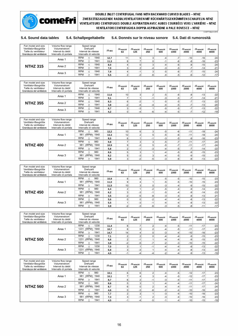
The values for Lwoct4 and Lw4 are given in the Sound Data Tables section 5.4..
Die Werte für LwoctA4 und Lw4 können aus der Schallpegeltabelle, (5.4) entnommen werden.
Les valeurs de LwoctA4 et Lw4 sont reportées dans le paragraphe 5.4
I valori di ∆Lwoct4 e ∆Lw4 sono riportati nelle tabelle del paragrafo 5.4..
5.2. Total Sound Power Level at the free outlet, Lw6
5.2. Niveau de Puissance Sonore Totale avec aspiration libre, Lw6
5.2. Livello di Potenza Sonora Totale con bocca libera, Lw6
The Total Sound Power Level, outside the termina-tion of the outlet duct, can be calculated with approxi-mation using of the "End Reflection" concept : part of the sound power generated by the fan at the discharge is reflected back into the duct when there is an abrupt termination. The value Lw6, at the outlet in a free discharge condi-tion, can be considered ap-proximately equal to the: Total Sound Power Level outside the termination of the outlet duct. The octave band values can be obtained subtracting, octave by octave, from the Lwoct4 values the reflected back portion of the sound power.
Der Gesamtschalleistungs-pegel - freiausblasend - kann näherungsweise nach dem End- Reflection-Verfah-ren berechnet werden. Bei abrupter Querschnittsverän-derung wird ein gewisser Anteil des Ventilatorgeräu-sches im Meßkanal reflek-tiert. Bei freiausblasendem Ein-satz entspricht der Lw6 Wert in etwa dem Gesamtschall-pegel. Die Werte über dem Oktav-band erhält man durch Sub-traktion der anteiligen Kor-rekturwerten Lwcorr von den Lwoct4 - Werten.
Le Niveau de Puissance Sonore Totale, à l'extérieur du conduit de refoulement, peut être déterminé an pre-mière approximation, en uti-lisant le concept de la "End Reflection", selon lequel une partie du son produit par le ventilateur ne sort pas du refoulement, mais vient ré-fléchi eà l'arrière. La valeur Lw6, à l'éxterieur de l’ouie libre (non canali-sée), peut être considérée approximativement égale au Niveau de Puissance So-nore Totale à la sortie du canal de refoulement. Le bruit en Bande d'Octave, à la sortie du conduit de re-foulement ou avec ouie libre, peut être déterminé en deduisant à Lwoct4, pour chaque Bande d'Octave, la partie du bruit refléchi.
Il Livello di Potenza Sonora Totale, all'esterno del canale di mandata, può essere de-terminato in prima appros-simazione usando il con-cetto della "End Reflection", secondo cui parte del suono prodotto dal ventilatore non esce dalla bocca del canale, ma viene riflesso all'indietro. Il valore Lw6, all'esterno della bocca di mandata libera (non canalizzata), può es-sere ritenuto approssimati-vamente uguale al Livello di Potenza Sonora Totale all'uscita dal canale di man-data. La rumorosità in Bande d'Ottava, all'uscita del ca-nale di mandata o con bocca libera, può essere determinata sottraendo a Lwoct4, per ogni Banda d'Ot-tava, la parte di rumore ri-flesso.
14
DOUBLE INLET CENTRIFUGAL FANS WITH BACKWARD CURVED BLADES – NTHZ
ZWEISEITIGSAUGENDE RADIALVENTILATOREN MIT RÜCKWÄRTSGEKRÜMMTEN SCHAUFELN- NTHZ
VENTILATEURS CENTRIFUGES DOUBLE ASPIRATION AVEC AUBES COURBÉES VERS L’ARRIÈRE – NTHZ
VENTILATORI CENTRIFUGHI A DOPPIA ASPIRAZIONE A PALE ROVESCE – NTHZ C-0077 March 2015
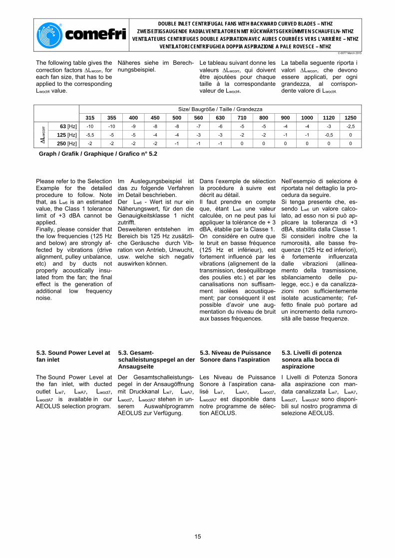
The following table gives the correction factors Lwcorr, for each fan size, that has to be applied to the corresponding Lwoct4 value.
Näheres siehe im Berech-nungsbeispiel.
Le tableau suivant donne les valeurs Lwcorr, qui doivent être ajoutées pour chaque taille à la correspondante valeur de Lwoct4.
La tabella seguente riporta i valori Lwcorr, che devono essere applicati, per ogni grandezza, al corrispon-dente valore di Lwoct4.
Please refer to the Selection Example for the detailed procedure to follow. Note that, as Lw6 is an estimated value, the Class 1 tolerance limit of +3 dBA cannot be applied. Finally, please consider that the low frequencies (125 Hz and below) are strongly af-fected by vibrations (drive alignment, pulley unbalance, etc) and by ducts not properly acoustically insu-lated from the fan; the final effect is the generation of additional low frequency noise.
Im Auslegungsbeispiel ist das zu folgende Verfahren im Detail beschrieben. Der Lw6 - Wert ist nur ein Näherungswert, für den die Genauigkeitsklasse 1 nicht zutrifft. Desweiteren entstehen im Bereich bis 125 Hz zusätzli-che Geräusche durch Vib-ration von Antrieb, Unwucht, usw. welche sich negativ auswirken können.
Dans l’exemple de sélection la procédure à suivre est décrit au détail. Il faut prendre en compte que, étant Lw6 une valeur calculée, on ne peut pas lui appliquer la tolérance de + 3 dBA, établie par la Classe 1. On considére en outre que le bruit en basse fréquence (125 Hz et inférieur), est fortement influencé par les vibrations (alignement de la transmission, deséquilibrage des poulies etc.) et par les canalisations non suffisam-ment isolées acoustique-ment; par conséquent il est possible d’avoir une aug-mentation du niveau de bruit aux basses fréquences.
Nell’esempio di selezione è riportata nel dettaglio la pro-cedura da seguire. Si tenga presente che, es-sendo Lw6 un valore calco-lato, ad esso non si può ap-plicare la tolleranza di +3 dBA, stabilita dalla Classe 1. Si consideri inoltre che la rumorosità, alle basse fre-quenze (125 Hz ed inferiori), è fortemente influenzata dalle vibrazioni (allinea-mento della trasmissione, sbilanciamento delle pu-legge, ecc.) e da canalizza-zioni non sufficientemente isolate acusticamente; l'ef-fetto finale può portare ad un incremento della rumoro-sità alle basse frequenze.
5.3. Sound Power Level at fan inlet
5.3. Gesamt-schalleistungspegel an der Ansaugseite
5.3. Niveau de Puissance Sonore dans l’aspiration
5.3. Livelli di potenza sonora alla bocca di aspirazione
The Sound Power Level at the fan inlet, with ducted outlet Lw7, LwA7, Lwoct7, LwoctA7 is available in our AEOLUS selection program.
Der Gesamtschalleistungs-pegel in der Ansaugöffnung mit Druckkanal Lw7, LwA7, Lwoct7, LwoctA7 stehen in un-serem Auswahlprogramm AEOLUS zur Verfügung.
Les Niveau de Puissance Sonore à l’aspiration cana-lisé Lw7, LwA7, Lwoct7, LwoctA7 est disponible dans notre programme de sélec-tion AEOLUS.
I Livelli di Potenza Sonora alla aspirazione con man-data canalizzata Lw7, LwA7, Lwoct7, LwoctA7 sono disponi-bili sul nostro programma di selezione AEOLUS.
15
DOUBLE INLET CENTRIFUGAL FANS WITH BACKWARD CURVED BLADES – NTHZ
ZWEISEITIGSAUGENDE RADIALVENTILATOREN MIT RÜCKWÄRTSGEKRÜMMTEN SCHAUFELN- NTHZ
VENTILATEURS CENTRIFUGES DOUBLE ASPIRATION AVEC AUBES COURBÉES VERS L’ARRIÈRE – NTHZ
VENTILATORI CENTRIFUGHI A DOPPIA ASPIRAZIONE A PALE ROVESCE – NTHZ C-0077 March 2015
5.4. Sound data tables 5.4. Schallpegeltabelle 5.4. Donnés sur le niveau sonore 5.4. Dati di rumorosità
Fan model and size Ventilator-Baugröße Taille du ventilateur
DOUBLE INLET CENTRIFUGAL FANS WITH BACKWARD CURVED BLADES – NTHZ
ZWEISEITIGSAUGENDE RADIALVENTILATOREN MIT RÜCKWÄRTSGEKRÜMMTEN SCHAUFELN- NTHZ
VENTILATEURS CENTRIFUGES DOUBLE ASPIRATION AVEC AUBES COURBÉES VERS L’ARRIÈRE – NTHZ
VENTILATORI CENTRIFUGHI A DOPPIA ASPIRAZIONE A PALE ROVESCE – NTHZ C-0077 March 2015
114
13,8 1467
0,994
22,84
96 dB(A)
1700 1467
83,2%
5.5. Selection Example 5.5. Auslegungsbeispiel 5.5. Exemple de sélection 5.5. Esempio di selezione
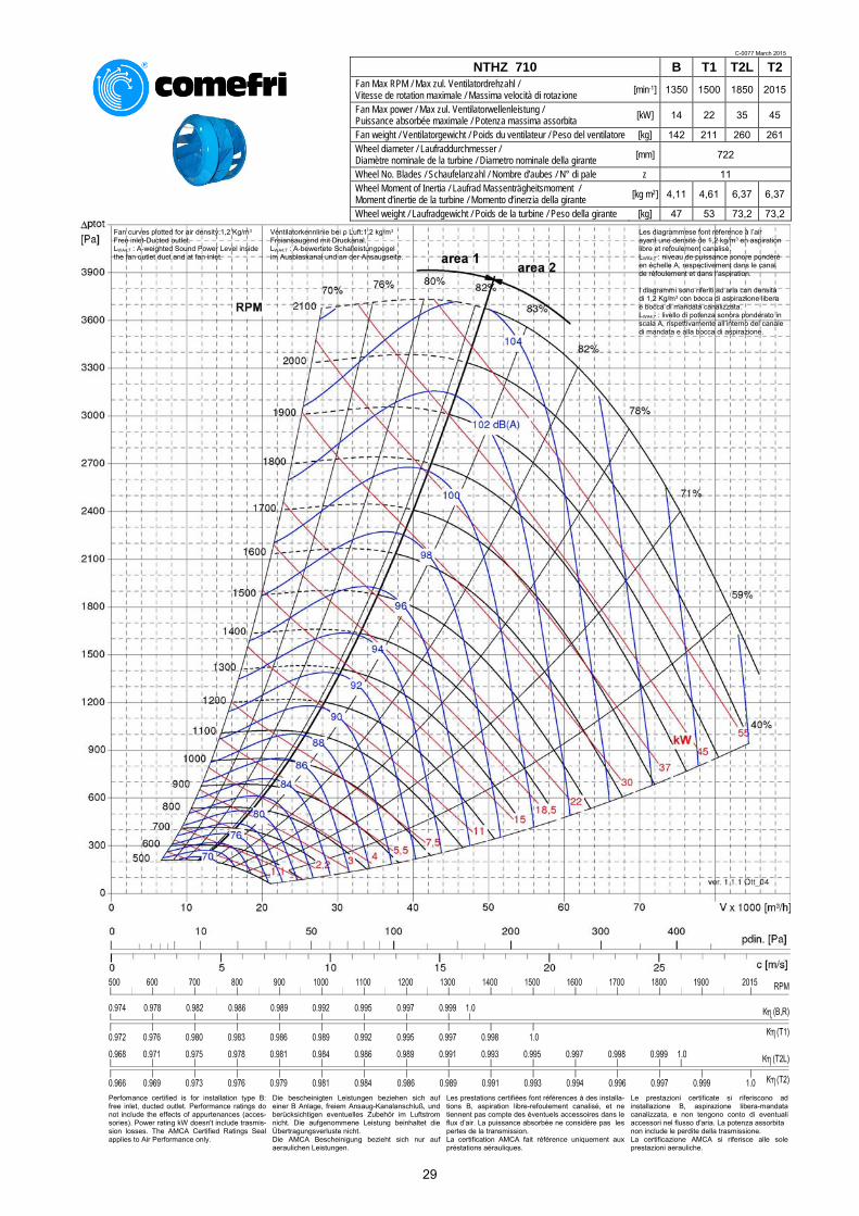
NTHZ 710 B T1 T2L T2Fan Max RPM / Max zul. Ventilatordrehzahl / Vitesse de rotation maximale / Massima velocità di rotazione [min-1] 1350 1500 1850 2015
Fan Max power / Max zul. Ventilatorwellenleistung / Puissance absorbée maximale / Potenza massima assorbita [kW] 14 22 35 45
Fan weight / Ventilatorgewicht / Poids du ventilateur / Peso del ventilatore [kg] 142 211 260 261 Wheel diameter / Laufraddurchmesser / Diamètre nominale de la turbine / Diametro nominale della girante [mm] 722
Wheel No. Blades / Schaufelanzahl / Nombre d'aubes / N° di pale z 11 Wheel Moment of Inertia / Laufrad Massenträgheitsmoment / Moment d'inertie de la turbine / Momento d’inerzia della girante [kg m2] 4,11 4,61 6,37 6,37
Wheel weight / Laufradgewicht / Poids de la turbine / Peso della girante [kg] 47 53 73,2 73,2
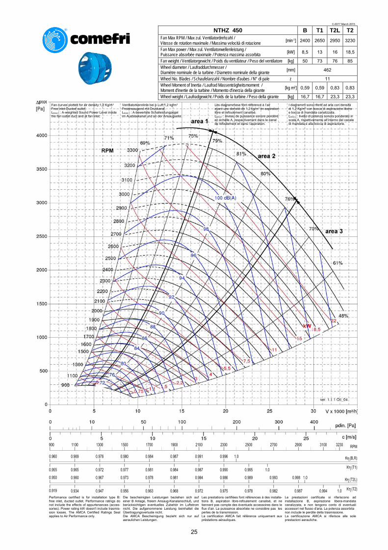
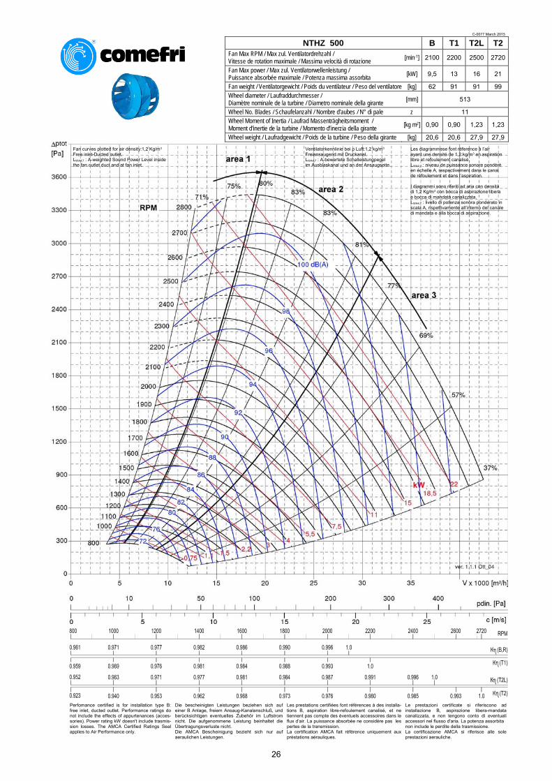
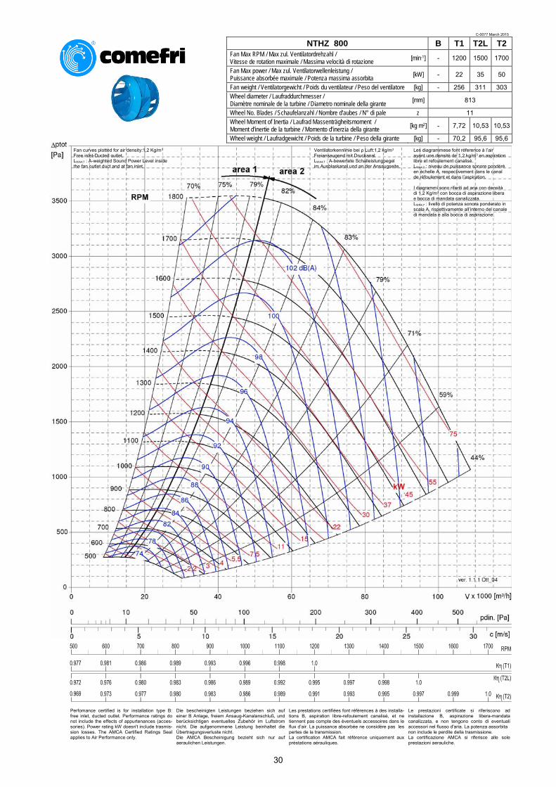
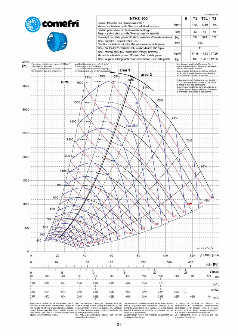
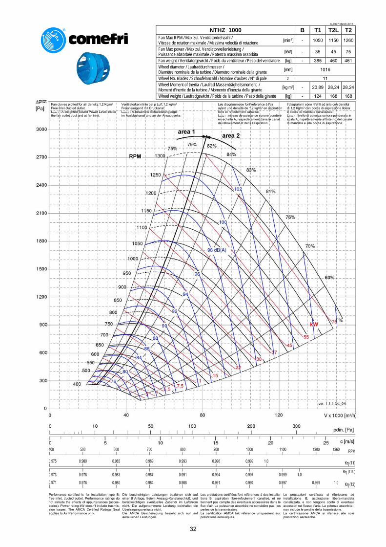
Fan curves plotted for air density:1,2 Kg/m3
Free inlet-Ducted outlet. LWA4;7 : A-weighted Sound Power Level inside the fan outlet duct and at fan inlet.
Ventilatorkennlinie bei ρ Luft:1,2 kg/m3
Freiansaugend mit Druckanal. LWA4;7 : A-bewertete Schalleistungpegel im Ausblaskanal und an der Ansaugseite.
I diagrammi sono riferiti ad aria con densità di 1,2 Kg/m3 con bocca di aspirazione libera e bocca di mandata canalizzata. LWA4;7 : livello di potenza sonora ponderato in scala A, rispettivamente all’interno del canale di mandata e alla bocca di aspirazione.
Les diagrammese font réference à l’air ayant une densité de 1,2 kg/m3 en aspiration libre et refoulement canalisé. LWA4;7 : niveau de puissance sonore pondéré en échelle A, respectivement dans le canal de réfoulement et dans l’aspiration.
18
DOUBLE INLET CENTRIFUGAL FANS WITH BACKWARD CURVED BLADES – NTHZ
ZWEISEITIGSAUGENDE RADIALVENTILATOREN MIT RÜCKWÄRTSGEKRÜMMTEN SCHAUFELN- NTHZ
VENTILATEURS CENTRIFUGES DOUBLE ASPIRATION AVEC AUBES COURBÉES VERS L’ARRIÈRE – NTHZ
VENTILATORI CENTRIFUGHI A DOPPIA ASPIRAZIONE A PALE ROVESCE – NTHZ C-0077 March 2015
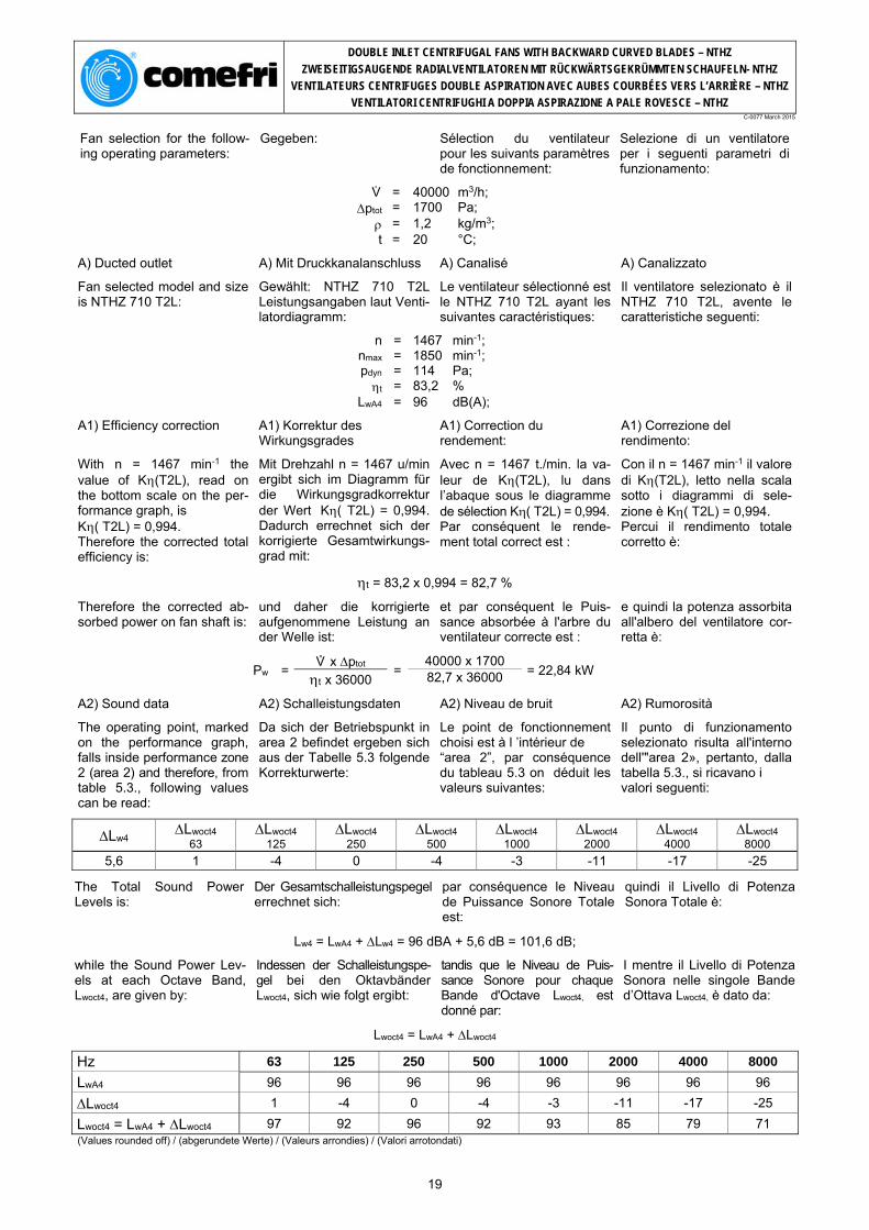
Fan selection for the follow-ing operating parameters:
Gegeben: Sélection du ventilateur pour les suivants paramètres de fonctionnement:
Selezione di un ventilatore per i seguenti parametri di funzionamento:
V° . = 40000 m3/h; ptot = 1700 Pa;
= 1,2 kg/m3; t = 20 °C;
A) Ducted outlet
Fan selected model and size is NTHZ 710 T2L:
A) Mit Druckkanalanschluss
Gewählt: NTHZ 710 T2L Leistungsangaben laut Venti-latordiagramm:
A) Canalisé
Le ventilateur sélectionné est le NTHZ 710 T2L ayant les suivantes caractéristiques:
A) Canalizzato
Il ventilatore selezionato è il NTHZ 710 T2L, avente le caratteristiche seguenti:
n = 1467 min-1; nmax = 1850 min-1; pdyn = 114 Pa; t = 83,2 %
LwA4 = 96 dB(A);
A1) Efficiency correction A1) Korrektur des Wirkungsgrades
A1) Correction du rendement:
A1) Correzione del rendimento:
With n = 1467 min-1 the value of K(T2L), read on the bottom scale on the per-formance graph, is K( T2L) = 0,994. Therefore the corrected total efficiency is:
Mit Drehzahl n = 1467 u/min ergibt sich im Diagramm für die Wirkungsgradkorrektur der Wert K( T2L) = 0,994. Dadurch errechnet sich der korrigierte Gesamtwirkungs-grad mit:
Avec n = 1467 t./min. la va-leur de K(T2L), lu dans l’abaque sous le diagramme de sélection K( T2L) = 0,994. Par conséquent le rende-ment total correct est :
Con il n = 1467 min-1 il valore di K(T2L), letto nella scala sotto i diagrammi di sele-zione è K( T2L) = 0,994. Percui il rendimento totale corretto è:
t = 83,2 x 0,994 = 82,7 %
Therefore the corrected ab-sorbed power on fan shaft is:
und daher die korrigierte aufgenommene Leistung an der Welle ist:
et par conséquent le Puis-sance absorbée à l'arbre du ventilateur correcte est :
e quindi la potenza assorbita all'albero del ventilatore cor-retta è:
Pw =V° . x ptot
=40000 x 1700
= 22,84 kW t x 36000 82,7 x 36000
A2) Sound data
The operating point, marked on the performance graph, falls inside performance zone 2 (area 2) and therefore, from table 5.3., following values can be read:
A2) Schalleistungsdaten
Da sich der Betriebspunkt in area 2 befindet ergeben sich aus der Tabelle 5.3 folgende Korrekturwerte:
A2) Niveau de bruit
Le point de fonctionnement choisi est à l ’intérieur de “area 2”, par conséquence du tableau 5.3 on déduit les valeurs suivantes:
A2) Rumorosità
Il punto di funzionamento selezionato risulta all'interno dell'"area 2», pertanto, dalla tabella 5.3., si ricavano i valori seguenti:
Lw4 Lwoct4 63
Lwoct4 125
Lwoct4 250
Lwoct4 500
Lwoct4 1000
Lwoct4 2000
Lwoct4 4000
Lwoct4 8000
5,6 1 -4 0 -4 -3 -11 -17 -25
The Total Sound Power Levels is:
Der Gesamtschalleistungspegel errechnet sich:
par conséquence le Niveau de Puissance Sonore Totale est:
quindi il Livello di Potenza Sonora Totale è:
Lw4 = LwA4 + Lw4 = 96 dBA + 5,6 dB = 101,6 dB;
while the Sound Power Lev-els at each Octave Band, Lwoct4, are given by:
Indessen der Schalleistungspe-gel bei den Oktavbänder Lwoct4, sich wie folgt ergibt:
tandis que le Niveau de Puis-sance Sonore pour chaque Bande d'Octave Lwoct4, est donné par:
I mentre il Livello di Potenza Sonora nelle singole Bande d’Ottava Lwoct4, è dato da:
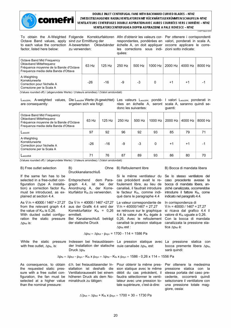
B) Free outlet selection If the same fan has to be selected in a free-outlet con-figuration (type A installa-tion) a correction factor Kfa must be introduced, as ex-plained at section 4.4.
As V° /n = 40000 / 1467 = 27,27 from the relevant graph 4.4 the value of Kfa is 0,26. With ducted outlet configu-ration the static pressure pfst is:
B) Ohne Druckkanalanschluß Entsprechend dem Para-graph 4.4, ist bei der Anordnung A, der Korre-kturfaktor Kfa zu verwenden.
Da V° /n = 40000 / 1467 =27,27 aus der Grafik 4.4 wird der Korrekturfaktor Kfa = 0,26 ermittelt. Bei Kanalanschluß beträgt der statische Druck
B) Refoulement libre Si le même ventilateur du cas précédent avait le re-foulement libre, au lieu de canalisé, il faudrait introduire le facteur Kfa, comme indi-qué dans le paragraphe 4.4
La valeur correspondante de V° /n = 40000/1467 = 27,27 se retrouve sur le graphique 4.4 la valeur de Kfa égale à 0,26. Avec le refoulement canalisé la pression statique pfst est :
B) Bocca di mandata libera Se lo stesso ventilatore del caso precedente avesse la bocca di mandata libera, an-zichè canalizzata, occorrerebbe introdurre il fattore Kfa, come indicato nel paragrafo 4.4.
In corrispondenza di V° /n = 40000 / 1467 = 27,27 si ricava dal grafico 4.4 il valore di Kfa uguale a 0,26. Con la bocca di mandata canalizzata la pressione sta-tica pfst è:
pfst ptot - pdyn = 1700 - 114 = 1586 Pa
While the static pressure with free outlet, pfa, is:
Indessen bei freiausblasen-der Installation der statische Druck pfa
La pression statique avec ouie canalisée pfa, est:
La pressione statica con bocca premente libera pfa, sarà quindi:
pfa ptot - pdyn - Kfa x pdyn pfst - Kfa x pdyn 1586 - 0,26 x 114 1556 Pa
As consequence, to obtain the requested static pres-sure with a free outlet con-figuration, the fan must be selected at a higher value than the nominal pressure:
d.h. bei freiausblasender In-stallation ist deshalb die Ventilatorauswahl bei einem höheren Druck als dem No-minaldruck zu tätigen:
Pour obtenir la même pres-sion statique avec le même débit du cas précédent, il faudra sélectionner le venti-lateur avec une pression to-tale supérieure, c'est-à-dire:
Per ottenere la medesima pressione statica con la stessa portata del caso pre-cedente, occorrerà quindi selezionare il ventilatore con una pressione totale mag-giore, ossia:
’ptot ptot + Kfa x pdyn 1700 + 30 1730 Pa
20
DOUBLE INLET CENTRIFUGAL FANS WITH BACKWARD CURVED BLADES – NTHZ
ZWEISEITIGSAUGENDE RADIALVENTILATOREN MIT RÜCKWÄRTSGEKRÜMMTEN SCHAUFELN- NTHZ
VENTILATEURS CENTRIFUGES DOUBLE ASPIRATION AVEC AUBES COURBÉES VERS L’ARRIÈRE – NTHZ
VENTILATORI CENTRIFUGHI A DOPPIA ASPIRAZIONE A PALE ROVESCE – NTHZ C-0077 March 2015
Therefore the new operating parameters are:
Als Folge ergeben sich die neuen Betriebsdaten mit:
Par conséquence les nou-veaux paramètres de fonc-tionnement seront:
Di conseguenza i nuovi pa-rametri di funzionamento sono:
n = 1477 min-1; LwA4 = 96 dB(A); pdyn = 114 Pa;
’t = t x ptot =83,2 x 1700
= 81,7 % ’ptot 1730
Pw = V° . x ptot =40000 x 1700
= 23,12 kW 't x 36000 81,7 x 36000
C) Free - outlet sound data
From table 5.2, for a NTHZ 710, the following values of Lwcorr can be obtained:
C) Schalleistungsdaten bei freien Ausbas:
Aus Graphik 5.2. können für den NTHZ 710 folgende Lwcorr Faktoren entnommen werden:
C) Bruit avec refulement libre:
Du tableau 5.2 on deduit pour le NTHZ 710 les cor-rections, Lwcorr suivantes:
C) Rumorosità con bocca di mandata libera:
Dalla tabella 5.2, si ricavano per l’NTHZ 710 le correzioni Lwcorr seguenti:
63 Hz -5 dB; 125 Hz -2 dB
LwoctA6, A-weighted values, are consequently:
ohne Druckkanalanschluss ergeben sich folgende LwoctA6 Werte:
par conséquence nous au-rons les valeurs suivantes LwoctA6:
Da cui i valori di LwoctA6, sono i seguenti:
Octave Band Mid Frequency Oktavband Mittefrequenz Fréquence moyenne de la Bande d'Octave Frequenza media della Banda d'Ottava
D) Altitude and temperature correction If the temperature and the altitude at which the fan will operate are not standard, the pressure value used for the selection must be previously re-calculated: Let’s consider the following parameters:
Air volume: 40000 m3/h Total pressure: 1445 Pa Temperature: 40 °C Altitude: 1000 m a.s.l.
From Graph 4.5, the value of K = 0,85 is obtained. The corrected pressure, to be used for the selection on the performance chart, is there-fore:
D) Korrektur für Temperatur- und Höhenabweichungen Weichen Temperatur oder Aufstellunshöhe ab, so ist die Druckerhöhung entsprechend zu korrigieren. z.B.
Volumenstrom: 40000 m3/h Gesamtdruckdifferenz:1445 Pa Temperatur : 40 °C Höhe:1000 m über Meeresspiegel.
Aus der Grafik 4.5 wird der Korrekturfaktor � K = 0,85 ermittelt. Damit ergibt sich:
D) Correction pour tempéra-ture et altitude différente Pour températures diffé-rentes de +20 °C et altitudes supérieures à 0 m s.n.m., les valeurs de la pression doi-vent être corrigées avant la sélection: En considérant les données suivantes:
Débit: 40000 m3/h Pression totale: 1445 Pa Température: 40 °C Altitude: 1000 m s.l.m.
Du graphique 4.5 on obtient K= 0,85, donc la valeur de pression à utilizer pour la sélection sera:
D) Correzione per tempera-tura e altitudine Per temperature ed altitudini diverse dai valori standard, i valori di pressione devono essere corretti prima della selezione. Consideriamo i dati seguenti:
Portata: 40000 m3/hPressione totale: 1445 Pa Temperatura: 40 °C Altitudine: 1000 m s.l.m.
Dal grafico 4.5 si ottiene K = 0,85 per cui il valore di pressione da utilizzare nella scelta sarà:
ptot corr = ptot =
1445 = 1700 Pa
K 0,85
The selected fan will be the same as selected in the ex-ample (paragraph (A)), with the same characteristics but the absorbed power will be:
Der ausgelegte Ventilator wird derselbe des Beispiels im (Pa-ragraph (A)) sein, mit den glei-chen Eigenschaften, allerdings wird die aufgenommene Leistung betragen:
Le ventilateur sélectionné sera par conséquent le même que celui de l’exemple (para-graphe (A)) avec les mêmes caractéristiques, mais la puis-sance absorbée sera:
Il ventilatore selezionato sarà pertanto lo stesso dell'esem-pio (paragrafo (A)), con le medesime caratteristiche, ma la potenza assorbita sarà:
Pwcorr = Pw x 0,85 = 22,84 x 0,85 = 19,41 kW
21
C-0077 March 2015
NTHZ 315 B T1 T2Fan Max RPM / Max zul. Ventilatordrehzahl / Vitesse de rotation maximale / Massima velocità di rotazione [min-1] 3550 3700 3900
Fan Max power / Max zul. Ventilatorwellenleistung / Puissance absorbée maximale / Potenza massima assorbita [kW] 5,5 7,5 9
Fan weight / Ventilatorgewicht / Poids du ventilateur / Peso del ventilatore [kg] 22 31 34,5 Wheel diameter / Laufraddurchmesser / Diamètre nominale de la turbine / Diametro nominale della girante [mm] 325
Wheel No. Blades / Schaufelanzahl / Nombre d'aubes / N° di pale z 11 Wheel Moment of Inertia / Laufrad Massenträgheitsmoment / Moment d'inertie de la turbine / Momento d’inerzia della girante [kg m2] 0,11 0,11 0,15
Wheel weight / Laufradgewicht / Poids de la turbine / Peso della girante [kg] 6,9 6,9 7,2
Fan curves plotted for air density:1,2 Kg/m3
Free inlet-Ducted outlet. LWA4;7 : A-weighted Sound Power Level inside the fan outlet duct and at fan inlet.
Ventilatorkennlinie bei ρ Luft:1,2 kg/m3
Freiansaugend mit Druckanal. LWA4;7 : A-bewertete Schalleistungpegel im Ausblaskanal und an der Ansaugseite.
Les diagrammese font réference à l’air ayant une densité de 1,2 kg/m3 en aspiration libre et refoulement canalisé. LWA4;7 : niveau de puissance sonore pondéré en échelle A, respectivement dans le canal de réfoulement et dans l’aspiration.
I diagrammi sono riferiti ad aria con densità di 1,2 Kg/m3 con bocca di aspirazione libera e bocca di mandata canalizzata. LWA4;7 : livello di potenza sonora ponderato in scala A, rispettivamente all’interno del canale di mandata e alla bocca di aspirazione.
Perfomance certified is for installation type B: free inlet, ducted outlet. Performance ratings do not include the effects of appurtenances (acces-sories). Power rating kW doesn't include trasmis-sion losses. The AMCA Certified Ratings Seal applies to Air Performance only.
Die bescheinigten Leistungen beziehen sich auf einer B Anlage, freiem Ansaug-Kanalanschluß, und berücksichtigen eventuelles Zubehör im Luftstrom nicht. Die aufgenommene Leistung beinhaltet die Übertragungsverluste nicht. Die AMCA Bescheinigung bezieht sich nur auf aeraulichen Leistungen.
Les prestations certifiées font références à des installa-tions B, aspiration libre-refoulement canalisé, et ne tiennent pas compte des éventuels accessoires dans le flux d’air. La puissance absorbée ne considére pas les pertes de la transmission. La certification AMCA fait référence uniquement aux préstations aérauliques.
Le prestazioni certificate si riferiscono adinstallazione B, aspirazione libera-mandata canalizzata, e non tengono conto di eventuali accessori nel flusso d'aria. La potenza assorbita non include le perdite della trasmissione. La certificazione AMCA si riferisce alle sole prestazioni aerauliche.
22
C-0077 March 2015
NTHZ 355 B T1 T2Fan Max RPM / Max zul. Ventilatordrehzahl / Vitesse de rotation maximale / Massima velocità di rotazione [min-1] 3150 3400 3850
Fan Max power / Max zul. Ventilatorwellenleistung / Puissance absorbée maximale / Potenza massima assorbita [kW] 6,5 9 12
Fan weight / Ventilatorgewicht / Poids du ventilateur / Peso del ventilatore [kg] 30 45 54 Wheel diameter / Laufraddurchmesser / Diamètre nominale de la turbine / Diametro nominale della girante [mm] 365
Wheel No. Blades / Schaufelanzahl / Nombre d'aubes / N° di pale z 11 Wheel Moment of Inertia / Laufrad Massenträgheitsmoment / Moment d'inertie de la turbine / Momento d’inerzia della girante [kg m2] 0,18 0,18 0,24
Wheel weight / Laufradgewicht / Poids de la turbine / Peso della girante [kg] 8,5 8,5 11,3
Fan curves plotted for air density:1,2 Kg/m3
Free inlet-Ducted outlet. LWA4;7 : A-weighted Sound Power Level inside the fan outlet duct and at fan inlet.
Ventilatorkennlinie bei ρ Luft:1,2 kg/m3
Freiansaugend mit Druckanal. LWA4;7 : A-bewertete Schalleistungpegel im Ausblaskanal und an der Ansaugseite.
Les diagrammese font réference à l’air ayant une densité de 1,2 kg/m3 en aspiration libre et refoulement canalisé. LWA4;7 : niveau de puissance sonore pondéré en échelle A, respectivement dans le canal de réfoulement et dans l’aspiration.
I diagrammi sono riferiti ad aria con densità di 1,2 Kg/m3 con bocca di aspirazione libera e bocca di mandata canalizzata. LWA4;7 : livello di potenza sonora ponderato in scala A, rispettivamente all’interno del canale di mandata e alla bocca di aspirazione.
Perfomance certified is for installation type B: free inlet, ducted outlet. Performance ratings do not include the effects of appurtenances (acces-sories). Power rating kW doesn't include trasmis-sion losses. The AMCA Certified Ratings Seal applies to Air Performance only.
Die bescheinigten Leistungen beziehen sich auf einer B Anlage, freiem Ansaug-Kanalanschluß, und berücksichtigen eventuelles Zubehör im Luftstrom nicht. Die aufgenommene Leistung beinhaltet die Übertragungsverluste nicht. Die AMCA Bescheinigung bezieht sich nur auf aeraulichen Leistungen.
Les prestations certifiées font références à des installa-tions B, aspiration libre-refoulement canalisé, et ne tiennent pas compte des éventuels accessoires dans le flux d’air. La puissance absorbée ne considére pas les pertes de la transmission. La certification AMCA fait référence uniquement aux préstations aérauliques.
Le prestazioni certificate si riferiscono adinstallazione B, aspirazione libera-mandata canalizzata, e non tengono conto di eventuali accessori nel flusso d'aria. La potenza assorbita non include le perdite della trasmissione. La certificazione AMCA si riferisce alle sole prestazioni aerauliche.
23
C-0077 March 2015
NTHZ 400 B T1 T2L T2Fan Max RPM / Max zul. Ventilatordrehzahl / Vitesse de rotation maximale / Massima velocità di rotazione [min-1] 2800 2950 3200 3600
Fan Max power / Max zul. Ventilatorwellenleistung / Puissance absorbée maximale / Potenza massima assorbita [kW] 6,5 9 11 14
Fan weight / Ventilatorgewicht / Poids du ventilateur / Peso del ventilatore [kg] 38 55 61 66 Wheel diameter / Laufraddurchmesser / Diamètre nominale de la turbine / Diametro nominale della girante [mm] 412
Wheel No. Blades / Schaufelanzahl / Nombre d'aubes / N° di pale z 11 Wheel Moment of Inertia / Laufrad Massenträgheitsmoment / Moment d'inertie de la turbine / Momento d’inerzia della girante [kg m2] 0,38 0,38 0,53 0,53
Wheel weight / Laufradgewicht / Poids de la turbine / Peso della girante [kg] 13,5 13,5 18,5 18,5
Fan curves plotted for air density:1,2 Kg/m3
Free inlet-Ducted outlet. LWA4;7 : A-weighted Sound Power Level inside the fan outlet duct and at fan inlet.
Ventilatorkennlinie bei ρ Luft:1,2 kg/m3
Freiansaugend mit Druckanal. LWA4;7 : A-bewertete Schalleistungpegel im Ausblaskanal und an der Ansaugseite.
Les diagrammese font réference à l’air ayant une densité de 1,2 kg/m3 en aspiration libre et refoulement canalisé. LWA4;7 : niveau de puissance sonore pondéré en échelle A, respectivement dans le canal de réfoulement et dans l’aspiration.
I diagrammi sono riferiti ad aria con densità di 1,2 Kg/m3 con bocca di aspirazione libera e bocca di mandata canalizzata. LWA4;7 : livello di potenza sonora ponderato in scala A, rispettivamente all’interno del canale di mandata e alla bocca di aspirazione.
Perfomance certified is for installation type B: free inlet, ducted outlet. Performance ratings do not include the effects of appurtenances (acces-sories). Power rating kW doesn't include trasmis-sion losses. The AMCA Certified Ratings Seal applies to Air Performance only.
Die bescheinigten Leistungen beziehen sich auf einer B Anlage, freiem Ansaug-Kanalanschluß, und berücksichtigen eventuelles Zubehör im Luftstrom nicht. Die aufgenommene Leistung beinhaltet die Übertragungsverluste nicht. Die AMCA Bescheinigung bezieht sich nur auf aeraulichen Leistungen.
Les prestations certifiées font références à des installa-tions B, aspiration libre-refoulement canalisé, et ne tiennent pas compte des éventuels accessoires dans le flux d’air. La puissance absorbée ne considére pas les pertes de la transmission. La certification AMCA fait référence uniquement aux préstations aérauliques.
Le prestazioni certificate si riferiscono adinstallazione B, aspirazione libera-mandatacanalizzata, e non tengono conto di eventuali accessori nel flusso d'aria. La potenza assorbita non include le perdite della trasmissione. La certificazione AMCA si riferisce alle sole prestazioni aerauliche.
24
C-0077 March 2015
NTHZ 450 B T1 T2L T2Fan Max RPM / Max zul. Ventilatordrehzahl / Vitesse de rotation maximale / Massima velocità di rotazione [min-1] 2400 2650 2950 3230
Fan Max power / Max zul. Ventilatorwellenleistung / Puissance absorbée maximale / Potenza massima assorbita [kW] 8,5 13 16 18,5
Fan weight / Ventilatorgewicht / Poids du ventilateur / Peso del ventilatore [kg] 50 73 76 85 Wheel diameter / Laufraddurchmesser / Diamètre nominale de la turbine / Diametro nominale della girante [mm] 462
Wheel No. Blades / Schaufelanzahl / Nombre d'aubes / N° di pale z 11 Wheel Moment of Inertia / Laufrad Massenträgheitsmoment / Moment d'inertie de la turbine / Momento d’inerzia della girante [kg m2] 0,59 0,59 0,83 0,83
Wheel weight / Laufradgewicht / Poids de la turbine / Peso della girante [kg] 16,7 16,7 23,3 23,3
Fan curves plotted for air density:1,2 Kg/m3
Free inlet-Ducted outlet. LWA4;7 : A-weighted Sound Power Level inside the fan outlet duct and at fan inlet.
Ventilatorkennlinie bei ρ Luft:1,2 kg/m3
Freiansaugend mit Druckanal. LWA4;7 : A-bewertete Schalleistungpegel im Ausblaskanal und an der Ansaugseite.
Les diagrammese font réference à l’air ayant une densité de 1,2 kg/m3 en aspiration libre et refoulement canalisé. LWA4;7 : niveau de puissance sonore pondéré en échelle A, respectivement dans le canal de réfoulement et dans l’aspiration.
I diagrammi sono riferiti ad aria con densità di 1,2 Kg/m3 con bocca di aspirazione libera e bocca di mandata canalizzata. LWA4;7 : livello di potenza sonora ponderato in scala A, rispettivamente all’interno del canale di mandata e alla bocca di aspirazione.
Perfomance certified is for installation type B: free inlet, ducted outlet. Performance ratings do not include the effects of appurtenances (acces-sories). Power rating kW doesn't include trasmis-sion losses. The AMCA Certified Ratings Seal applies to Air Performance only.
Die bescheinigten Leistungen beziehen sich auf einer B Anlage, freiem Ansaug-Kanalanschluß, und berücksichtigen eventuelles Zubehör im Luftstrom nicht. Die aufgenommene Leistung beinhaltet die Übertragungsverluste nicht. Die AMCA Bescheinigung bezieht sich nur auf aeraulichen Leistungen.
Les prestations certifiées font références à des installa-tions B, aspiration libre-refoulement canalisé, et ne tiennent pas compte des éventuels accessoires dans le flux d’air. La puissance absorbée ne considére pas les pertes de la transmission. La certification AMCA fait référence uniquement aux préstations aérauliques.
Le prestazioni certificate si riferiscono adinstallazione B, aspirazione libera-mandata canalizzata, e non tengono conto di eventuali accessori nel flusso d'aria. La potenza assorbita non include le perdite della trasmissione. La certificazione AMCA si riferisce alle sole prestazioni aerauliche.
25
C-0077 March 2015
NTHZ 500 B T1 T2L T2Fan Max RPM / Max zul. Ventilatordrehzahl / Vitesse de rotation maximale / Massima velocità di rotazione [min-1] 2100 2200 2500 2720
Fan Max power / Max zul. Ventilatorwellenleistung / Puissance absorbée maximale / Potenza massima assorbita [kW] 9,5 13 16 21
Fan weight / Ventilatorgewicht / Poids du ventilateur / Peso del ventilatore [kg] 62 91 91 99 Wheel diameter / Laufraddurchmesser / Diamètre nominale de la turbine / Diametro nominale della girante [mm] 513
Wheel No. Blades / Schaufelanzahl / Nombre d'aubes / N° di pale z 11 Wheel Moment of Inertia / Laufrad Massenträgheitsmoment / Moment d'inertie de la turbine / Momento d’inerzia della girante [kg m2] 0,90 0,90 1,23 1,23
Wheel weight / Laufradgewicht / Poids de la turbine / Peso della girante [kg] 20,6 20,6 27,9 27,9
Fan curves plotted for air density:1,2 Kg/m3
Free inlet-Ducted outlet. LWA4;7 : A-weighted Sound Power Level inside the fan outlet duct and at fan inlet.
Ventilatorkennlinie bei ρ Luft:1,2 kg/m3
Freiansaugend mit Druckanal. LWA4;7 : A-bewertete Schalleistungpegel im Ausblaskanal und an der Ansaugseite.
Les diagrammese font réference à l’air ayant une densité de 1,2 kg/m3 en aspiration libre et refoulement canalisé. LWA4;7 : niveau de puissance sonore pondéré en échelle A, respectivement dans le canal de réfoulement et dans l’aspiration.
I diagrammi sono riferiti ad aria con densità di 1,2 Kg/m3 con bocca di aspirazione libera e bocca di mandata canalizzata. LWA4;7 : livello di potenza sonora ponderato in scala A, rispettivamente all’interno del canale di mandata e alla bocca di aspirazione.
Perfomance certified is for installation type B: free inlet, ducted outlet. Performance ratings do not include the effects of appurtenances (acces-sories). Power rating kW doesn't include trasmis-sion losses. The AMCA Certified Ratings Seal applies to Air Performance only.
Die bescheinigten Leistungen beziehen sich auf einer B Anlage, freiem Ansaug-Kanalanschluß, und berücksichtigen eventuelles Zubehör im Luftstrom nicht. Die aufgenommene Leistung beinhaltet die Übertragungsverluste nicht. Die AMCA Bescheinigung bezieht sich nur auf aeraulichen Leistungen.
Les prestations certifiées font références à des installa-tions B, aspiration libre-refoulement canalisé, et ne tiennent pas compte des éventuels accessoires dans le flux d’air. La puissance absorbée ne considére pas les pertes de la transmission. La certification AMCA fait référence uniquement aux préstations aérauliques.
Le prestazioni certificate si riferiscono adinstallazione B, aspirazione libera-mandata canalizzata, e non tengono conto di eventuali accessori nel flusso d'aria. La potenza assorbita non include le perdite della trasmissione. La certificazione AMCA si riferisce alle sole prestazioni aerauliche.
26
C-0077 March 2015
NTHZ 560 B T1 T2L T2Fan Max RPM / Max zul. Ventilatordrehzahl / Vitesse de rotation maximale / Massima velocità di rotazione [min-1] 1950 2050 2400 2600
Fan Max power / Max zul. Ventilatorwellenleistung / Puissance absorbée maximale / Potenza massima assorbita [kW] 11,5 18,5 28 35
Fan weight / Ventilatorgewicht / Poids du ventilateur / Peso del ventilatore [kg] 89 127 167 168 Wheel diameter / Laufraddurchmesser / Diamètre nominale de la turbine / Diametro nominale della girante [mm] 575
Wheel No. Blades / Schaufelanzahl / Nombre d'aubes / N° di pale z 11 Wheel Moment of Inertia / Laufrad Massenträgheitsmoment / Moment d'inertie de la turbine / Momento d’inerzia della girante [kg m2] 1,55 1,55 2,29 2,29
Wheel weight / Laufradgewicht / Poids de la turbine / Peso della girante [kg] 23,4 23,4 41,4 41,4
Fan curves plotted for air density:1,2 Kg/m3
Free inlet-Ducted outlet. LWA4;7 : A-weighted Sound Power Level inside the fan outlet duct and at fan inlet.
Ventilatorkennlinie bei ρ Luft:1,2 kg/m3
Freiansaugend mit Druckanal. LWA4;7 : A-bewertete Schalleistungpegel im Ausblaskanal und an der Ansaugseite.
Les diagrammese font réference à l’air ayant une densité de 1,2 kg/m3 en aspiration libre et refoulement canalisé. LWA4;7 : niveau de puissance sonore pondéré en échelle A, respectivement dans le canal de réfoulement et dans l’aspiration.
I diagrammi sono riferiti ad aria con densità di 1,2 Kg/m3 con bocca di aspirazione libera e bocca di mandata canalizzata. LWA4;7 : livello di potenza sonora ponderato in scala A, rispettivamente all’interno del canale di mandata e alla bocca di aspirazione.
Perfomance certified is for installation type B: free inlet, ducted outlet. Performance ratings do not include the effects of appurtenances (acces-sories). Power rating kW doesn't include trasmis-sion losses. The AMCA Certified Ratings Seal applies to Air Performance only.
Die bescheinigten Leistungen beziehen sich auf einer B Anlage, freiem Ansaug-Kanalanschluß, und berücksichtigen eventuelles Zubehör im Luftstrom nicht. Die aufgenommene Leistung beinhaltet die Übertragungsverluste nicht. Die AMCA Bescheinigung bezieht sich nur auf aeraulichen Leistungen.
Les prestations certifiées font références à des installa-tions B, aspiration libre-refoulement canalisé, et ne tiennent pas compte des éventuels accessoires dans le flux d’air. La puissance absorbée ne considére pas les pertes de la transmission. La certification AMCA fait référence uniquement aux préstations aérauliques.
Le prestazioni certificate si riferiscono adinstallazione B, aspirazione libera-mandata canalizzata, e non tengono conto di eventuali accessori nel flusso d'aria. La potenza assorbita non include le perdite della trasmissione. La certificazione AMCA si riferisce alle sole prestazioni aerauliche.
27
C-0077 March 2015
NTHZ 630 B T1 T2L T2Fan Max RPM / Max zul. Ventilatordrehzahl / Vitesse de rotation maximale / Massima velocità di rotazione [min-1] 1550 1650 2100 2275
Fan Max power / Max zul. Ventilatorwellenleistung / Puissance absorbée maximale / Potenza massima assorbita [kW] 11,5 18,5 28 40
Fan weight / Ventilatorgewicht / Poids du ventilateur / Peso del ventilatore [kg] 111 154 196 198 Wheel diameter / Laufraddurchmesser / Diamètre nominale de la turbine / Diametro nominale della girante [mm] 646
Wheel No. Blades / Schaufelanzahl / Nombre d'aubes / N° di pale z 11 Wheel Moment of Inertia / Laufrad Massenträgheitsmoment / Moment d'inertie de la turbine / Momento d’inerzia della girante [kg m2] 2,56 2,56 3,61 3,61
Wheel weight / Laufradgewicht / Poids de la turbine / Peso della girante [kg] 37 37 51,8 51,8
Fan curves plotted for air density:1,2 Kg/m3
Free inlet-Ducted outlet. LWA4;7 : A-weighted Sound Power Level inside the fan outlet duct and at fan inlet.
Ventilatorkennlinie bei ρ Luft:1,2 kg/m3
Freiansaugend mit Druckanal. LWA4;7 : A-bewertete Schalleistungpegel im Ausblaskanal und an der Ansaugseite.
Les diagrammese font réference à l’air ayant une densité de 1,2 kg/m3 en aspiration libre et refoulement canalisé. LWA4;7 : niveau de puissance sonore pondéré en échelle A, respectivement dans le canal de réfoulement et dans l’aspiration.
I diagrammi sono riferiti ad aria con densità di 1,2 Kg/m3 con bocca di aspirazione libera e bocca di mandata canalizzata. LWA4;7 : livello di potenza sonora ponderato in scala A, rispettivamente all’interno del canale di mandata e alla bocca di aspirazione.
Perfomance certified is for installation type B: free inlet, ducted outlet. Performance ratings do not include the effects of appurtenances (acces-sories). Power rating kW doesn't include trasmis-sion losses. The AMCA Certified Ratings Seal applies to Air Performance only.
Die bescheinigten Leistungen beziehen sich auf einer B Anlage, freiem Ansaug-Kanalanschluß, und berücksichtigen eventuelles Zubehör im Luftstrom nicht. Die aufgenommene Leistung beinhaltet die Übertragungsverluste nicht. Die AMCA Bescheinigung bezieht sich nur auf aeraulichen Leistungen.
Les prestations certifiées font références à des installa-tions B, aspiration libre-refoulement canalisé, et ne tiennent pas compte des éventuels accessoires dans le flux d’air. La puissance absorbée ne considére pas les pertes de la transmission. La certification AMCA fait référence uniquement aux préstations aérauliques.
Le prestazioni certificate si riferiscono adinstallazione B, aspirazione libera-mandata canalizzata, e non tengono conto di eventuali accessori nel flusso d'aria. La potenza assorbita non include le perdite della trasmissione. La certificazione AMCA si riferisce alle sole prestazioni aerauliche.
28
C-0077 March 2015
NTHZ 710 B T1 T2L T2Fan Max RPM / Max zul. Ventilatordrehzahl / Vitesse de rotation maximale / Massima velocità di rotazione [min-1] 1350 1500 1850 2015
Fan Max power / Max zul. Ventilatorwellenleistung / Puissance absorbée maximale / Potenza massima assorbita [kW] 14 22 35 45
Fan weight / Ventilatorgewicht / Poids du ventilateur / Peso del ventilatore [kg] 142 211 260 261 Wheel diameter / Laufraddurchmesser / Diamètre nominale de la turbine / Diametro nominale della girante [mm] 722
Wheel No. Blades / Schaufelanzahl / Nombre d'aubes / N° di pale z 11 Wheel Moment of Inertia / Laufrad Massenträgheitsmoment / Moment d'inertie de la turbine / Momento d’inerzia della girante [kg m2] 4,11 4,61 6,37 6,37
Wheel weight / Laufradgewicht / Poids de la turbine / Peso della girante [kg] 47 53 73,2 73,2
Fan curves plotted for air density:1,2 Kg/m3
Free inlet-Ducted outlet. LWA4;7 : A-weighted Sound Power Level inside the fan outlet duct and at fan inlet.
Ventilatorkennlinie bei ρ Luft:1,2 kg/m3
Freiansaugend mit Druckanal. LWA4;7 : A-bewertete Schalleistungpegel im Ausblaskanal und an der Ansaugseite.
Les diagrammese font réference à l’air ayant une densité de 1,2 kg/m3 en aspiration libre et refoulement canalisé. LWA4;7 : niveau de puissance sonore pondéré en échelle A, respectivement dans le canal de réfoulement et dans l’aspiration.
I diagrammi sono riferiti ad aria con densità di 1,2 Kg/m3 con bocca di aspirazione libera e bocca di mandata canalizzata. LWA4;7 : livello di potenza sonora ponderato in scala A, rispettivamente all’interno del canale di mandata e alla bocca di aspirazione.
Perfomance certified is for installation type B: free inlet, ducted outlet. Performance ratings do not include the effects of appurtenances (acces-sories). Power rating kW doesn't include trasmis-sion losses. The AMCA Certified Ratings Seal applies to Air Performance only.
Die bescheinigten Leistungen beziehen sich auf einer B Anlage, freiem Ansaug-Kanalanschluß, und berücksichtigen eventuelles Zubehör im Luftstrom nicht. Die aufgenommene Leistung beinhaltet die Übertragungsverluste nicht. Die AMCA Bescheinigung bezieht sich nur auf aeraulichen Leistungen.
Les prestations certifiées font références à des installa-tions B, aspiration libre-refoulement canalisé, et ne tiennent pas compte des éventuels accessoires dans le flux d’air. La puissance absorbée ne considére pas les pertes de la transmission. La certification AMCA fait référence uniquement aux préstations aérauliques.
Le prestazioni certificate si riferiscono adinstallazione B, aspirazione libera-mandata canalizzata, e non tengono conto di eventuali accessori nel flusso d'aria. La potenza assorbita non include le perdite della trasmissione. La certificazione AMCA si riferisce alle sole prestazioni aerauliche.
29
C-0077 March 2015
NTHZ 800 B T1 T2L T2Fan Max RPM / Max zul. Ventilatordrehzahl / Vitesse de rotation maximale / Massima velocità di rotazione [min-1] - 1200 1500 1700
Fan Max power / Max zul. Ventilatorwellenleistung / Puissance absorbée maximale / Potenza massima assorbita [kW] - 22 35 50
Fan weight / Ventilatorgewicht / Poids du ventilateur / Peso del ventilatore [kg] - 256 311 303 Wheel diameter / Laufraddurchmesser / Diamètre nominale de la turbine / Diametro nominale della girante [mm] 813
Wheel No. Blades / Schaufelanzahl / Nombre d'aubes / N° di pale z 11 Wheel Moment of Inertia / Laufrad Massenträgheitsmoment / Moment d'inertie de la turbine / Momento d’inerzia della girante [kg m2] - 7,72 10,53 10,53
Wheel weight / Laufradgewicht / Poids de la turbine / Peso della girante [kg] - 70,2 95,6 95,6
Fan curves plotted for air density:1,2 Kg/m3
Free inlet-Ducted outlet. LWA4;7 : A-weighted Sound Power Level inside the fan outlet duct and at fan inlet.
Ventilatorkennlinie bei ρ Luft:1,2 kg/m3
Freiansaugend mit Druckanal. LWA4;7 : A-bewertete Schalleistungpegel im Ausblaskanal und an der Ansaugseite.
Les diagrammese font réference à l’air ayant une densité de 1,2 kg/m3 en aspiration libre et refoulement canalisé. LWA4;7 : niveau de puissance sonore pondéré en échelle A, respectivement dans le canal de réfoulement et dans l’aspiration.
I diagrammi sono riferiti ad aria con densità di 1,2 Kg/m3 con bocca di aspirazione libera e bocca di mandata canalizzata. LWA4;7 : livello di potenza sonora ponderato in scala A, rispettivamente all’interno del canale di mandata e alla bocca di aspirazione.
Perfomance certified is for installation type B: free inlet, ducted outlet. Performance ratings do not include the effects of appurtenances (acces-sories). Power rating kW doesn't include trasmis-sion losses. The AMCA Certified Ratings Seal applies to Air Performance only.
Die bescheinigten Leistungen beziehen sich auf einer B Anlage, freiem Ansaug-Kanalanschluß, und berücksichtigen eventuelles Zubehör im Luftstrom nicht. Die aufgenommene Leistung beinhaltet die Übertragungsverluste nicht. Die AMCA Bescheinigung bezieht sich nur auf aeraulichen Leistungen.
Les prestations certifiées font références à des installa-tions B, aspiration libre-refoulement canalisé, et ne tiennent pas compte des éventuels accessoires dans le flux d’air. La puissance absorbée ne considére pas les pertes de la transmission. La certification AMCA fait référence uniquement aux préstations aérauliques.
Le prestazioni certificate si riferiscono adinstallazione B, aspirazione libera-mandata canalizzata, e non tengono conto di eventuali accessori nel flusso d'aria. La potenza assorbita non include le perdite della trasmissione. La certificazione AMCA si riferisce alle sole prestazioni aerauliche.
30
C-0077 March 2015
NTHZ 900 B T1 T2L T2Fan Max RPM / Max zul. Ventilatordrehzahl / Vitesse de rotation maximale / Massima velocità di rotazione [min-1] - 1200 1350 1500
Fan Max power / Max zul. Ventilatorwellenleistung / Puissance absorbée maximale / Potenza massima assorbita [kW] - 33 45 70
Fan weight / Ventilatorgewicht / Poids du ventilateur / Peso del ventilatore [kg] - 331 379 377 Wheel diameter / Laufraddurchmesser / Diamètre nominale de la turbine / Diametro nominale della girante [mm] 913
Wheel No. Blades / Schaufelanzahl / Nombre d'aubes / N° di pale z 11 Wheel Moment of Inertia / Laufrad Massenträgheitsmoment / Moment d'inertie de la turbine / Momento d’inerzia della girante [kg m2] - 14,48 17,59 17,59
Wheel weight / Laufradgewicht / Poids de la turbine / Peso della girante [kg] - 103 126,5 126,5
Fan curves plotted for air density:1,2 Kg/m3
Free inlet-Ducted outlet. LWA4;7 : A-weighted Sound Power Level inside the fan outlet duct and at fan inlet.
Ventilatorkennlinie bei ρ Luft:1,2 kg/m3
Freiansaugend mit Druckanal. LWA4;7 : A-bewertete Schalleistungpegel im Ausblaskanal und an der Ansaugseite.
Les diagrammese font réference à l’air ayant une densité de 1,2 kg/m3 en aspiration libre et refoulement canalisé. LWA4;7 : niveau de puissance sonore pondéré en échelle A, respectivement dans le canal de réfoulement et dans l’aspiration.
I diagrammi sono riferiti ad aria con densità di 1,2 Kg/m3 con bocca di aspirazione libera e bocca di mandata canalizzata. LWA4;7 : livello di potenza sonora ponderato in scala A, rispettivamente all’interno del canale di mandata e alla bocca di aspirazione.
Perfomance certified is for installation type B: free inlet, ducted outlet. Performance ratings do not include the effects of appurtenances (acces-sories). Power rating kW doesn't include trasmis-sion losses. The AMCA Certified Ratings Seal applies to Air Performance only.
Die bescheinigten Leistungen beziehen sich auf einer B Anlage, freiem Ansaug-Kanalanschluß, und berücksichtigen eventuelles Zubehör im Luftstrom nicht. Die aufgenommene Leistung beinhaltet die Übertragungsverluste nicht. Die AMCA Bescheinigung bezieht sich nur auf aeraulichen Leistungen.
Les prestations certifiées font références à des installa-tions B, aspiration libre-refoulement canalisé, et ne tiennent pas compte des éventuels accessoires dans le flux d’air. La puissance absorbée ne considére pas les pertes de la transmission. La certification AMCA fait référence uniquement aux préstations aérauliques.
Le prestazioni certificate si riferiscono adinstallazione B, aspirazione libera-mandata canalizzata, e non tengono conto di eventuali accessori nel flusso d'aria. La potenza assorbita non include le perdite della trasmissione. La certificazione AMCA si riferisce alle sole prestazioni aerauliche.
31
C-0077 March 2015
NTHZ 1000 B T1 T2L T2Fan Max RPM / Max zul. Ventilatordrehzahl / Vitesse de rotation maximale / Massima velocità di rotazione [min-1] - 1050 1150 1260
Fan Max power / Max zul. Ventilatorwellenleistung / Puissance absorbée maximale / Potenza massima assorbita [kW] - 35 45 75
Fan weight / Ventilatorgewicht / Poids du ventilateur / Peso del ventilatore [kg] - 385 460 461 Wheel diameter / Laufraddurchmesser / Diamètre nominale de la turbine / Diametro nominale della girante [mm] 1016
Wheel No. Blades / Schaufelanzahl / Nombre d'aubes / N° di pale z 11 Wheel Moment of Inertia / Laufrad Massenträgheitsmoment / Moment d'inertie de la turbine / Momento d’inerzia della girante [kg m2] - 20,89 28,24 28,24
Wheel weight / Laufradgewicht / Poids de la turbine / Peso della girante [kg] - 124 168 168
Fan curves plotted for air density:1,2 Kg/m3
Free inlet-Ducted outlet. LWA4;7 : A-weighted Sound Power Level inside the fan outlet duct and at fan inlet.
Ventilatorkennlinie bei ρ Luft:1,2 kg/m3
Freiansaugend mit Druckanal. LWA4;7 : A-bewertete Schalleistungpegel im Ausblaskanal und an der Ansaugseite.
Les diagrammese font réference à l’air ayant une densité de 1,2 kg/m3 en aspiration libre et refoulement canalisé. LWA4;7 : niveau de puissance sonore pondéré en échelle A, respectivement dans le canal de réfoulement et dans l’aspiration.
I diagrammi sono riferiti ad aria con densità di 1,2 Kg/m3 con bocca di aspirazione libera e bocca di mandata canalizzata. LWA4;7 : livello di potenza sonora ponderato in scala A, rispettivamente all’interno del canale di mandata e alla bocca di aspirazione.
Perfomance certified is for installation type B: free inlet, ducted outlet. Performance ratings do not include the effects of appurtenances (acces-sories). Power rating kW doesn't include trasmis-sion losses. The AMCA Certified Ratings Seal applies to Air Performance only.
Die bescheinigten Leistungen beziehen sich auf einer B Anlage, freiem Ansaug-Kanalanschluß, und berücksichtigen eventuelles Zubehör im Luftstrom nicht. Die aufgenommene Leistung beinhaltet die Übertragungsverluste nicht. Die AMCA Bescheinigung bezieht sich nur auf aeraulichen Leistungen.
Les prestations certifiées font références à des installa-tions B, aspiration libre-refoulement canalisé, et ne tiennent pas compte des éventuels accessoires dans le flux d’air. La puissance absorbée ne considére pas les pertes de la transmission. La certification AMCA fait référence uniquement aux préstations aérauliques.
Le prestazioni certificate si riferiscono adinstallazione B, aspirazione libera-mandata canalizzata, e non tengono conto di eventuali accessori nel flusso d'aria. La potenza assorbita non include le perdite della trasmissione. La certificazione AMCA si riferisce alle sole prestazioni aerauliche.
32
C-0077 March 2015
NTHZ 1120 B T1 T2Fan Max RPM / Max zul. Ventilatordrehzahl / Vitesse de rotation maximale / Massima velocità di rotazione [min-1] - 825 1175
Fan Max power / Max zul. Ventilatorwellenleistung / Puissance absorbée maximale / Potenza massima assorbita [kW] - 35 100
Fan weight / Ventilatorgewicht / Poids du ventilateur / Peso del ventilatore [kg] - 710 869 Wheel diameter / Laufraddurchmesser / Diamètre nominale de la turbine / Diametro nominale della girante [mm] 1136
Wheel No. Blades / Schaufelanzahl / Nombre d'aubes / N° di pale z 11 Wheel Moment of Inertia / Laufrad Massenträgheitsmoment / Moment d'inertie de la turbine / Momento d’inerzia della girante [kg m2] - 38,43 57,67
Wheel weight / Laufradgewicht / Poids de la turbine / Peso della girante [kg] - 219 337
Fan curves plotted for air density:1,2 Kg/m3
Free inlet-Ducted outlet. LWA4;7 : A-weighted Sound Power Level inside the fan outlet duct and at fan inlet.
Ventilatorkennlinie bei ρ Luft:1,2 kg/m3
Freiansaugend mit Druckanal. LWA4;7 : A-bewertete Schalleistungpegel im Ausblaskanal und an der Ansaugseite.
Les diagrammese font réference à l’air ayant une densité de 1,2 kg/m3 en aspiration libre et refoulement canalisé. LWA4;7 : niveau de puissance sonore pondéré en échelle A, respectivement dans le canal de réfoulement et dans l’aspiration.
I diagrammi sono riferiti ad aria con densità di 1,2 Kg/m3 con bocca di aspirazione libera e bocca di mandata canalizzata. LWA4;7 : livello di potenza sonora ponderato in scala A, rispettivamente all’interno del canale di mandata e alla bocca di aspirazione.
Perfomance certified is for installation type B: free inlet, ducted outlet. Performance ratings do not include the effects of appurtenances (acces-sories). Power rating kW doesn't include trasmis-sion losses. The AMCA Certified Ratings Seal applies to Air Performance only.
Die bescheinigten Leistungen beziehen sich auf einer B Anlage, freiem Ansaug-Kanalanschluß, und berücksichtigen eventuelles Zubehör im Luftstrom nicht. Die aufgenommene Leistung beinhaltet die Übertragungsverluste nicht. Die AMCA Bescheinigung bezieht sich nur auf aeraulichen Leistungen.
Les prestations certifiées font références à des installa-tions B, aspiration libre-refoulement canalisé, et ne tiennent pas compte des éventuels accessoires dans le flux d’air. La puissance absorbée ne considére pas les pertes de la transmission. La certification AMCA fait référence uniquement aux préstations aérauliques.
Le prestazioni certificate si riferiscono adinstallazione B, aspirazione libera-mandata canalizzata, e non tengono conto di eventuali accessori nel flusso d'aria. La potenza assorbita non include le perdite della trasmissione. La certificazione AMCA si riferisce alle sole prestazioni aerauliche.
33
C-0077 March 2015
NTHZ 1250 B T1 T2Fan Max RPM / Max zul. Ventilatordrehzahl / Vitesse de rotation maximale / Massima velocità di rotazione [min-1] - 765 1050
Fan Max power / Max zul. Ventilatorwellenleistung / Puissance absorbée maximale / Potenza massima assorbita [kW] - 50 130
Fan weight / Ventilatorgewicht / Poids du ventilateur / Peso del ventilatore [kg] - 990 1045Wheel diameter / Laufraddurchmesser / Diamètre nominale de la turbine / Diametro nominale della girante [mm] 1266
Wheel No. Blades / Schaufelanzahl / Nombre d'aubes / N° di pale z 11 Wheel Moment of Inertia / Laufrad Massenträgheitsmoment / Moment d'inertie de la turbine / Momento d’inerzia della girante [kg m2] - 64,72 86,14
Wheel weight / Laufradgewicht / Poids de la turbine / Peso della girante [kg] - 292 383
Fan curves plotted for air density:1,2 Kg/m3
Free inlet-Ducted outlet. LWA4;7 : A-weighted Sound Power Level inside the fan outlet duct and at fan inlet. Ventilatorkennlinie bei ρ Luft:1,2 kg/m3
Freiansaugend mit Druckanal. LWA4;7 : A-bewertete Schalleistungpegel im Ausblaskanal und an der Ansaugseite.
Les diagrammese font réference à l’air ayant une densité de 1,2 kg/m3 en aspiration libre et refoulement canalisé. LWA4;7 : niveau de puissance sonore pondéré en échelle A, respectivement dans le canal de réfoulement et dans l’aspiration.
I diagrammi sono riferiti ad aria con densità di 1,2 Kg/m3 con bocca di aspirazione libera e bocca di mandata canalizzata. LWA4;7 : livello di potenza sonora ponderato in scala A, rispettivamente all’interno del canale di mandata e alla bocca di aspirazione.
Perfomance certified is for installation type B: free inlet, ducted outlet. Performance ratings do not include the effects of appurtenances (acces-sories). Power rating kW doesn't include trasmis-sion losses. The AMCA Certified Ratings Seal applies to Air Performance only.
Die bescheinigten Leistungen beziehen sich auf einer B Anlage, freiem Ansaug-Kanalanschluß, und berücksichtigen eventuelles Zubehör im Luftstrom nicht. Die aufgenommene Leistung beinhaltet die Übertragungsverluste nicht. Die AMCA Bescheinigung bezieht sich nur auf aeraulichen Leistungen.
Les prestations certifiées font références à des installa-tions B, aspiration libre-refoulement canalisé, et ne tiennent pas compte des éventuels accessoires dans le flux d’air. La puissance absorbée ne considére pas les pertes de la transmission. La certification AMCA fait référence uniquement aux préstations aérauliques.
Le prestazioni certificate si riferiscono adinstallazione B, aspirazione libera-mandata canalizzata, e non tengono conto di eventuali accessori nel flusso d'aria. La potenza assorbita non include le perdite della trasmissione. La certificazione AMCA si riferisce alle sole prestazioni aerauliche.
34
DOUBLE INLET CENTRIFUGAL FANS WITH BACKWARD CURVED BLADES – NTHZ
ZWEISEITIGSAUGENDE RADIALVENTILATOREN MIT RÜCKWÄRTSGEKRÜMMTEN SCHAUFELN- NTHZ
VENTILATEURS CENTRIFUGES DOUBLE ASPIRATION AVEC AUBES COURBÉES VERS L’ARRIÈRE – NTHZ
VENTILATORI CENTRIFUGHI A DOPPIA ASPIRAZIONE A PALE ROVESCE – NTHZ C-0077 March 2015
7. Fan dimensions 7. Ventilatorabmessungen 7. Dimensions 7. Dimensioni
8.1. Mounting Feet ..F 8.1. Füsse ..F 8.1. Pieds de support ..F 8.1. Piedi di sostegno ..F
Standard feet are manufac-tured in galvanized steel sheet. They are supplied as a separate item, with the necessary fixing screws. For dimensions see page 35.
Standard-Füsse werden aus verzinktem Stahlblech her-gestellt und separat mit den entsprechenden Befesti-gungschrauben geliefert. Die Füsse sind bis ein-schliesslich Ventilator-Bau-größe 710 lieferbar. Abmes-sungen siehe Seite 35.
Les supports F sont réalisés en tôle d'acier galvanisé et sont fournis séparément avec les vis de fixation né-cessaires. Ces accessoires sont disponibles jusqu'à la taille 710 comprise. Les di-mensions se trouvent à la page 35.
I sostegni F sono realizzati in lamiera zincata e sono forniti separatamente con le necessarie viti di fissaggio. Tali accessori sono disponi-bili fino alla grandezza 710 compresa. Le dimensioni si trovano a pagina 35.
43
DOUBLE INLET CENTRIFUGAL FANS WITH BACKWARD CURVED BLADES – NTHZ
ZWEISEITIGSAUGENDE RADIALVENTILATOREN MIT RÜCKWÄRTSGEKRÜMMTEN SCHAUFELN- NTHZ
VENTILATEURS CENTRIFUGES DOUBLE ASPIRATION AVEC AUBES COURBÉES VERS L’ARRIÈRE – NTHZ
VENTILATORI CENTRIFUGHI A DOPPIA ASPIRAZIONE A PALE ROVESCE – NTHZ C-0077 March 2015
They are manufactured in galvanized steel sheet. They can be supplied as a separate item, with the nec-essary fixing screws, or al-ready fitted on fan. This accessory is available up to and including size 710. For dimensions see page 36.
Rechteckrahmen R sind aus verzinktem Stahlblech herge-stellt. Sie sind entweder lose mit Befestigungschrauben oder montiert lieferbar. Rechteckrahmen R sind bis einschliesslich Baugröße 710 lieferbar. Abmessun-gen, siehe Seite 36.
Ceux-ci sont construits en acier galvanisé et peuvent être fournis déjà montés au ventilateur ou séparément avec la visserie nécessaire. Ces accessoires sont dispo-nibles jusqu'à la taille 710 comprise. Les dimensions se trouvent à la page 36.
Essi sono costruiti in acciaio zincato e possono essere forniti sia separatamente, con le viti necessarie per il fissaggio, oppure già mon-tati sul ventilatore. Tali ac-cessori sono disponibili fino alla grandezza 710 com-presa. Le dimensioni si tro-vano a pagina 36.
It can be supplied separately or fitted on customer’s re-quirement. Manufactured in galvanised steel, its dimen-sions and drillings are given in the fan dimension tables. Sizes 1120 and 1250 come with integral outlet flange on the casing.
Der Ausblasflansch kann lose oder am Ventilator montiert geliefert werden. Hergestellt aus verzinktem Stahlblech; Abmessungen und Bohrungen können aus der Ventilatortabelle ent-nommen werden. Bei den Baugrößen 1120 und 1250 ist der Ausblasflansch am Gehäuse standardmässig vorhanden.
La bride peut être fournie séparément ou fixée au ventilateur. Contruite en acier galvanisé, elle a les dimensions et les trous qui sont reportés sur les dessins d'encombrement des venti-lateurs. Les ventilateurs taille 1120 et 1250 ont la bride de refoulement inte-grée sur la volute.
Può essere fornita separa-tamente o fissata al ventila-tore. Costruita in acciaio zincato, ha le dimensioni e le forature riportate sui dise-gni d’ingombro dei ventila-tori. I ventilatori taglia 1120 e 1250 hanno la flangia pre-mente integrata nella cassa.
8.4. Flexible outlet connection ..AEL
8.4. Elastischer Ausblasstutzen ..AEL
8.4. Manchette souple au refoulement ..AEL
8.4. Giunto antivibrante premente ..AEL
The flexible connection for the outlet is manufactured with a polyester / PVC fabric and two matching flanges, made in galvanised steel sheet. The “L” dimension, valid for all fan sizes, is equal to 155 mm. Special flexible connections can be manufactured on request.
Der elastische Ausblasstut-zen besteht aus zwei Aus-blasflanschen mit dazwi-schen liegendem Polyester /PVC Band. Die Einbaulänge ”L”, be-trägt ca. 155 mm einheitlich für alle Baugrössen. Spezi-elle Ausführungen auf An-frage.
Elle est construite par une bande en polyester / PVC fixée à deux brides en acier. La dimension "L"est égale pour toutes les tailles et me-sure 155 mm, lorsque la manchette est toute éten-due. Manchettes souples spéciales peuvent être four-nies sur demande.
È costituito da una fascia in Poliestere / PVC fissata a due flange di acciaio. La quota “L ” è uguale per tutte le grandezze e vale 155 mm con il giunto total-mente esteso. Giunti antivibranti speciali possono essere forniti su richiesta.
Usually fitted at the lowest part of the fan to facilitate drain of condensation.
Die Positionierung des Kon-densatablaufstutzen erfolgt an der tiefsten Stelle des Ventila-torgehäuses oder gemäß ent-sprechender Kundenspezifika-tion.
Elle est fixée sur la partie inférieure de la volute pour permettre un écoulement facile des condensats.
È fissato nella parte inferiore della cassa in modo da per-mettere un facile drenaggio della condensa.
Ø“
NTHZ 315 ÷ 1000 1/2“
NTHZ 1120; NTHZ 1250 1“
44
DOUBLE INLET CENTRIFUGAL FANS WITH BACKWARD CURVED BLADES – NTHZ
ZWEISEITIGSAUGENDE RADIALVENTILATOREN MIT RÜCKWÄRTSGEKRÜMMTEN SCHAUFELN- NTHZ
VENTILATEURS CENTRIFUGES DOUBLE ASPIRATION AVEC AUBES COURBÉES VERS L’ARRIÈRE – NTHZ
VENTILATORI CENTRIFUGHI A DOPPIA ASPIRAZIONE A PALE ROVESCE – NTHZ C-0077 March 2015
8.6. Inspection door ..I 8.6. Inspektionsklappe ..I 8.6. Porte de visite ..I 8.6. Portina d’ispezione ..I
Can be fitted to the fan cas-ing and consists of a galva-nised steel plate fixed by quick release screws. A synthetic gasket prevents leakage. Position of the in-spection door must be clearly stated in the order.
Die Inspektionsklappe aus verzinktem Stahlblech wird mit einer synthetischen Dichtung versehen, und mit dem Gehäuse verschraubt. Die lage der Inspektionsklappe muß bei der Auftragserteilung eindeutig angegeben werden.
Elle est construite en acier galvanisé et est fixée avec des vis à la volute. Une gar-niture assure une tenue parfaite. La position de la porte de visite doit être clai-rement indiquée au moment de la commande.
È costruita in acciaio zincato ed è fissata mediante viti alla cassa. Una guarnizione ga-rantisce una perfetta tenuta. La posizione della portina d’ispezione deve essere chiaramente indicata al mo-mento dell’ordine.
a b NTHZ 315 ÷ 560 220 240
NTHZ 630 ÷ 1000 270 290
NTHZ 1120; NTHZ 1250 560 560
8.7. Outlet guard..AS 8.7. Ausblasschutzgitter
..AS 8.7. Grillage au refoulement..AS
8.7. Rete di protezione in mandata ..AS
Industrial safety regulations specify that reliable guards must be provided for rotating machine elements. Inlet protections are available, in full accordance to EN ISO 13857, European safety regulations.
Schutzvorschriften für rotie-rende Maschinen verlangen eine entsprechende Schutzvorrichtung. Das Ausblasschutz- gitter AS wird nach EN ISO 13857 gefertigt.
Il est construit selon la norme EN ISO 13857, con- cernant la sécurité pour l'utilisation des Machines tournantes.
È costruita secondo le norme EN ISO 13857, sulla sicurezza nell’uso delle macchine rotanti.
8.8. Inlet guard ..ZS
8.8. Ansaugschutzgitter ..ZS
8.8. Grillage à l'aspiration ..ZS
8.8. Rete di protezione aspirante..ZS
Industrial safety regulations specify that reliable guards must be provided for rotat-ing machine elements. Out-let protections are available, according to EN ISO 13857
Schutzvorschriften für rotie-rende Maschinen verlangen eine entsprechende Schutzvorrichtung. Das Ansaug- schutzgitter AS wird nach EN ISO 13857 gefertigt.
Il est construit selon la norme EN ISO 13857, con- cernant la sécurité pour l'utilisation des machines tournantes.
È costruita secondo le norme EN ISO 13857, sulla sicurezza nell’uso delle macchine rotanti.
8.9. Belt guard ..RIS
8.9. Keilriemen- schutzgitter ..RIS
8.9. Carter protection courroies..RIS
8.9. Carter protezione cinghie ..RIS
The belt guard is manufac-tured in a corrosion proof steel wire mesh, in full ac-cordance with EN ISO 13857. Dimensions denoted with “a”, “b” and “c” depend on the corresponding pulley diameters and number of belts. Upon request, access for rpm measurement can be provided.
Das Keilriemenschutzgitter besteht aus verzinktem Stahlgitter nach EN ISO 13857. Die Abmessungen “a”, “b” und “c” hängen von der Antriebsauslegung ab. Auf Anfrage ist eine Dreh-zahlmeßöffnung lieferbar.
Il est construit en fil d'acier galvanisé et respecte les normes EN ISO 13857. Les dimensions "a" "b" et "c" dépendent des diamètres et du nombre de gorge des poulies montées. Sur de-mande on peut fournir une sonde de prise de la vitesse de rotation.
È costruito in filo d’acciaio zincato e rispetta le norme EN ISO 13857. Le dimen-sioni “a ” “b ” e “c ” dipen-dono dai diametri e dal nu-mero di gole delle pulegge montate. Si può fornire a richiesta un accesso per la misura della velocità di rota-zione.
45
DOUBLE INLET CENTRIFUGAL FANS WITH BACKWARD CURVED BLADES – NTHZ
ZWEISEITIGSAUGENDE RADIALVENTILATOREN MIT RÜCKWÄRTSGEKRÜMMTEN SCHAUFELN- NTHZ
VENTILATEURS CENTRIFUGES DOUBLE ASPIRATION AVEC AUBES COURBÉES VERS L’ARRIÈRE – NTHZ
VENTILATORI CENTRIFUGHI A DOPPIA ASPIRAZIONE A PALE ROVESCE – NTHZ C-0077 March 2015
8.10. Shaft guard ..WES
8.10. Wellenschutz ..WES
8.10. Protection à l'arbre ..WES
8.10. Carter protezione albero ..WES
A wire meshed shaft guard is available, for both B/R and T versions.
Der Wellenschutz aus Stahlgitter ist für alle Venti-latorausführungen lieferbar.
Il est construit en grillage et est disponible pour tou-tesles versions.
È costruito in rete ed è di-sponibile per tutte le ver-sioni.
8.11. Anti vibration mountings, rubber type ..DAG and Anti vibration mountings, spring type ..DAM
8.11.Gummischwin-gungsdämpfer Typ ..DAG und Federschwingun- gsdämpfer Typ ..DAM
8.11. Supports amortisseurs, en caoutchouc ..DAG et à essort d'acier ..DAM
8.11. Supporti antivibranti,in gomma ..DAG e a molla ..DAM
The anti-vibration mountings are normally delivered sepa-rately, together with the necessary bolts and nuts to fix the mountings to the baseframe. They are se-lected taking into considera-tion the total weight of the fan, belt drive, motor and all the ordered accessories. On request, and to suit special applications, spring type mountings can be ordered and supplied.
Es könne Gummischwin-gungsdämpfer (DAG) oder Federschwingunsdämpfer (DAM) verwendet warden. Die Schwingungsdämpfer warden mit den ents-prechenden Schrauben und Muttern separate geliefert. Die Auslegung erfolgt nach dem Gesamtgewicht und der Drehzahl des Ventila-tors.
Les supports amortisseurs sont normalement fournis séparément et avec les vis nécessaires pour la fixation au châssis. Ils sont sélec-tionnés tenant compte de la masse totale supportée (ventilateur, moteur, trans-mission, accessoires, etc). Sur demande pour applica-tion spéciale on peut fournir des types de supports par-ticuliers.
I supporti antivibranti sono normalmente forniti sepa-ratamente e con le viti ne-cessarie per il fissaggio al basamento. Sono selezio-nati tenendo conto della massa totale sopportata (ventilatore, motore, tra-smissione, accessori, ecc.). A richiesta e per applicazioni speciali si possono fornire tipi di supporti particolari.
Five sizes of motor rails are available, covering motor sizes from 71 to 315 in-cluded.
Motorspannschienen sind für Motorbaugrößen von 71 bis 315 lieferbar.
Pour les tailles des moteurs de 71 à 315 compris on uti-lise cinq modèles de rails tendeurs, glissières.
Per le grandezze di motori dalla 71 alla 315 compresa si usano cinque modelli di slitta tendicinghia.
46
DOUBLE INLET CENTRIFUGAL FANS WITH BACKWARD CURVED BLADES – NTHZ
ZWEISEITIGSAUGENDE RADIALVENTILATOREN MIT RÜCKWÄRTSGEKRÜMMTEN SCHAUFELN- NTHZ
VENTILATEURS CENTRIFUGES DOUBLE ASPIRATION AVEC AUBES COURBÉES VERS L’ARRIÈRE – NTHZ
VENTILATORI CENTRIFUGHI A DOPPIA ASPIRAZIONE A PALE ROVESCE – NTHZ C-0077 March 2015
8.13. Motor base plates ..SY
8.13. Motorspann=
schlitten ..SY 8.13. Base support moteur ..SY
8.13. Base portamotore ..SY
Two sizes of base plates are available, for motor sizes from 63 to 132 included.
Motorspannschlitten sind für Motorbaugrößen von 63 bis 132 lieferbar.
Deux modèles de base sup-port moteur sont disponibles pour les moteurs de la taille 63 à la taille 132 comprise.
Due modelli di base porta-motore sono disponibili per i motori dalla grandezza 63 alla grandezza 132 com-presa.
8.14. Standard baseframe ..GR
8.14. Standard-Grundrahmen ..GR
8.14. Châssis standards ..GR
8.14. Basamenti standard ..GR
Made of carbon steel, welded “C” profile, and painted. For dimensions see the relevant pages 40/41.
Aus U-Profil geschweißt und lackiert. Abmessungen siehe Seiten 40/41.
Ils sont construits en profilé à “C” d'acier et peints. Pour les dimensions consulter les pages 40 et 41.
Sono costruiti in profilati a “C” d’acciaio verniciato. Per le dimensioni consultare le pagine 40 e 41.
8.15. Spark proof execution ATEX 95 ..ATEX
8.15. FunkenschutzATEX 95 ..ATEX
8.15. Exécution antié-tincelle ATEX 95 ..ATEX
8.15. Esecuzione antiscin-tilla ATEX 95 ..ATEX
The NTHZ fans can be sup-plied in accordance with ATEX directive 94/9/CE: in this case the technical solu-tions adopted to comply with the requirements of the rele-vant standards imply a re-duction in the fan perfor-mances, reduction that in accordance with standards ISO 13348 - DIN24166 can be defined as a one-step in-crease of the tolerance class originally defined for the standard construction, i.e. from tolerance Class 1 to tolerance Class 2. For more technical details and selec-tions please contact Comefri sales office.
Die NTHZ Ventilatoren kön-nen in der ATEX Ausführung gemäss der Richtlinie 94/9/CE geliefert werden. In diesem Fall implizieren die angewandten technischen Lösungen gemäss der rele-vanten Richtlinie eine Re-duktion der Leistungen der Ventilatoren. Die Reduktion kann gemäss der Normen ISO 13348 - DIN24166 als eine Ein-Schritt Erhöhung der Toleranzklasse definiert warden, welche ursprünglich für die Standardkonstruktion defi-niert war, d.h. von Toler-anzklasse 1 bis Toleranz-klasse 2. Für weitere techni-sche Details und Auslegun-gen, bitten wir Sie die Fa. Comefri zu kontaktieren.
Les ventilateurs NTHZ peu-vent être fournis en version ATEX selon la directive 94/9/CE. Dans ce cas, les solutions techniques ad-optées, en conformité avec les normes standards de ré-ference, comportent une ré-duction des préstations du ventilateur qui, selon les normes ISO 13348 - DIN24166 peut être définie et calculée comme aug-mentation d'une classe de tolérance sur les prestations fournies par rapport au ven-tilateur fourni en version standard (de Classe 1 à Classe 2). Pour toutes in-formations concernant sé-lection et details téchniques, Veuillez SVP contacter Comefri.
I ventilatori NTHZ possono essere forniti in esecuzione ATEX in accordo alla direttiva 94/9/CE; In questo caso le specifiche costruttive adot-tate, in conformità alle norme di riferimento, comportano una riduzione delle presta-zioni del ventilatore che, in relazione a quanto definito dalle norme ISO 13348 - DIN24166, è valutabile e quantificabile nell'aumento di una "Classe di tolleranza" sulle prestazioni fornite, ri-spetto a quelle previste per lo stesso ventilatore in esecu-zione standard (da Classe 1 a Classe 2). Nello specifico, per la selezione ed i dettagli tecnici e/o informazioni commerciali, contattare Co-mefri.
47
DOUBLE INLET CENTRIFUGAL FANS WITH BACKWARD CURVED BLADES – NTHZ
ZWEISEITIGSAUGENDE RADIALVENTILATOREN MIT RÜCKWÄRTSGEKRÜMMTEN SCHAUFELN- NTHZ
VENTILATEURS CENTRIFUGES DOUBLE ASPIRATION AVEC AUBES COURBÉES VERS L’ARRIÈRE – NTHZ
VENTILATORI CENTRIFUGHI A DOPPIA ASPIRAZIONE A PALE ROVESCE – NTHZ C-0077 March 2015
8.16. Airflow measuring device
8.16. Volumenstrom –Meßeinrichtung
8.16. Dispositif pour la mesure du débit
8.16. Dispositivo per la misurazione della portata
The NTHZ fans can be fitted with a device for measuring and controlling the air vol-ume, with a tolerance of 5 to 10%, (normal operating conditions). The measuring device accu-racy is guaranteed by an extensive series of tests performed in our state of art test laboratory, for the whole fan range dimensions. The device consist of two or more static pressure meas-uring points, mounted di-rectly into both inlet cones. The measuring points are manifolded together via a flexible pipe ring. Therefore only a single pipe connec-tion to the pressure meas-uring device is required.. When the fan is installed in an AHU, the pressure differ-ential to be measured is between the suction cham-ber of the AHU (where the fan is installed) and the flow measuring device (see drawing page.49). This pressure difference can be converted into the volume flow by the following for-mula:
Die Ventilatoren NTHZ kön-nen mit einer Einrichtung zur Volumenstrombestimmung und -überwachung ausge-stattet werden (Abweichung 5-10% unter normalen Be-triebsbedingungen). Um die Genauigkeit zu ge-währleisten, wurden in unse-rem Labor für jeden Venti-lator der NTHZ-Reihe ent-sprechende Kalibrierfaktoren ermittelt. Die Volumenstrom-Meßein-richtung besteht aus zwei oder mehreren Meßstellen in jeder Einströmdüse, die durch eine Ringleitung (In-nendurchmesser 3-5 mm) verbunden sind. Als der Ventilator in ein Ge-rät eingebaut wird, muß der Differenzdruck zwischen Ge-rät –Ansaug und Ringleitung gemessen werden (siehe Schema auf Seite 49). Dieser Differenzdruck wird wie folgt zur Ermittlung des Volumenstromes verwendet:
Les ventilateurs peuvent être équipés avec un dispo-sitif pour la mesure et le contrôle du débit en condi-tions normales d’utilisation, avec une marge d’erreur maximum de lecture entre le 5 et le 10%. Afin de garantir ce degré de précision sur l’indication du débit, le me-sureur a été calibré pour chaque taille de la série NTHZ dans le Laboratoire d’Essais Aérauliques Comefri. Le système con-siste à placer deux ou plu-sieurs prises statiques de pression sur les pavillons d’aspiration connectés entre elles par un circuit anu-laire,c’est-à-dire un tube avec diamètre interne entre 3 et 5 mm fixé aux pavillons par des attaches prévues à cet effet. Quand le ventila-teur est installé dans une unité la différence de pres-sion qui doit être mesurée est entre l’aspiration de l’unité et la prise anulaire prévue sur les pavillons (voir schéma à page 49). La diffé-rence de pression statique obtenue est la p à utiliser pour la définition du débit.
I ventilatori possono essere dotati di un dispositivo per la misurazione ed il controllo della portata che nelle con-dizioni normali di impiego comporta un errore massimo di lettura compreso tra il 5 e il 10%. Per garantire il grado di precisione nella in-dicazione della portata, il misuratore è stato calibrato nel Laboratorio Prove Ae-rauliche Comefri per ogni ventilatore della serie NTHZ. Il sistema consiste di due o più prese statiche di pres-sione realizzate su entrambi i boccagli di aspirazione collegati tra loro mediante un circuito anulare con ap-posito attacco per il tubo di diametro interno compreso tra i 3 e i 5 mm. Quando il ventilatore è inserito in una unità, la differenza di pres-sione che deve essere misu-rata è tra l’aspirazione dell’unità e la presa anulare predisposta sui boccagli (vedi schema pag.49). La differenza di pressione sta-tica così ottenuta è la p da utilizzarsi nella espressione della portata.
Airflow Volumenstrom Débit Portata V° [ m3/h ]
Calibration factor depending on fan size
Kalibrierfaktor abhängig von dem Ventilatorgröße
Facteurs de calibrage relatifs à la taille du ventilateur
Fattore di calibrazione dipendente dalla grandezza del ventilatore
K(*)
Air density Luftdichte Densité d’air Densità dell’aria [ kg/m3 ]
Differential pressure Differenzdruck Différence de pression Differenza di pressione ∆p [ Pa ]
(*) Our maintenance manual details the relevant calibration factor (K)
(*) K-Werte befinden sich auf der Gebrauch- und Wartungsanleitung
(*) Les valeurs de K sont sur le ma-nuel d’utilisation et d’entreten
(*) I valori di K sono riportati sul ma-nuale di uso e manutenzione
The device with the measuring ring (Fig. 11) can be used with the Electronic Cometer (Fig.10).
The pressure measuring device must be ordered with the fan, as it must be factory in-stalled.
Das System mit der Ringleitung (Bild 11) dagegen dem Electronic Cometer (Bild.10).
Die Ventilatoren müssen mit der be-reits installierten Meßeinrichtung be-stellt werden.
Fig.10
Le deuxième sys-tème à circuit an-nulaire (Fig.11), peut être jumelé au Cometer Eléctro-nique (Fig.10).
Les ventilateurs doi-vent être demandés avec système de mesuration installé, au moment de la commande.
Il sistema a circuito anulare (Fig.11), può essere abbi-nato all’ Electronic Cometer (Fig.10).
I ventilatori devono essere richiesti all’atto dell’ordine con il sistema di misurazione in-stallato.
48
p 2
V
K
DOUBLE INLET CENTRIFUGAL FANS WITH BACKWARD CURVED BLADES – NTHZ
ZWEISEITIGSAUGENDE RADIALVENTILATOREN MIT RÜCKWÄRTSGEKRÜMMTEN SCHAUFELN- NTHZ
VENTILATEURS CENTRIFUGES DOUBLE ASPIRATION AVEC AUBES COURBÉES VERS L’ARRIÈRE – NTHZ
VENTILATORI CENTRIFUGHI A DOPPIA ASPIRAZIONE A PALE ROVESCE – NTHZ C-0077 March 2015
8.16.1. Fan installation recommendations
8.16.1. Anweisungen zum Einbau der Ventilatoren in den Einheiten
8.16.1. Instructions sur l’installation des ventilateurs dans les unités
8.16.1. Indicazioni sulla installazione dei ventilatori nelle unità.
The distance between the fan inlet and the AHU walls “R” (Fig.11) is vital for a cor-rect fan operation. Here at-tached useful indications quoted in the fans literature. Known the air velocity at the fan inlet, and the distance of the fan inlet from the AHU walls, the pU can be ob-tained from graph 8.16. For a correct fan selection, pU have to be added to the circuit total losses.
Der Abstand “R” (Bild.11) ist die Voraussetzug eines gu-ten Betriebs des Ventilators. In der Folge wird es erwähnt was in der Fachliteratur um das Betreffende zu finden ist. Sind die Luftgeschiwindigkeit beim Ansaug des Ventilators v und der Abstand R be-kannt, kann man aus der Grafik 8.16 pU ermitteln, das dem Gesamtverlust der Anlage zu addieren ist, um den Ventilator korrekt aus-zulegen.
La distance “R” (Fig.11) est très importante pour le bon foncionnement du ventila-teur. Vous trouvez de suite ce que la littérature spéciali-sée mentionne à ce propos. En connaissant la vitesse de l’air à l’aspiration du ventila-teur v, et la distance R, du graphique 8.16 on obtient pU qui doit être additionnée aux pertes totales du circuit afin de selectionner correc-tement le ventilateur.
La distanza “R” (Fig.11) è di fondamentale importanza per il buon funzionamento del ventilatore. Di seguito si riporta quanto indicato nella letteratura specializzata sull’argomento. Nota la velocità dell’aria all’aspirazione del ventilatore v, e la distanza R, dal grafico 8.16 si ricava pU che deve essere sommata alle perdite totali del circuito al fine di selezionare correttamente il ventilatore.
No influence Kein Einfluß Pas d’influence Nessuna influenza R = 0,92 x øI Zone 1 Zone 1 Zone 1 Zona 1 R = 0,75 x øI Zone 2 Zone 2 Zone 2 Zona 2 R = 0,50 x øI
Distance of the fan inlet from the AHU walls
Abstand zwischen Ansaug und Einheitwand
Distance entre l’aspiration et la paroi de l’unité
Distanza della bocca di aspirazione dalla parete dell’unità
R [mm]
Diameter of the inlet of the fan that coincide with nominal wheel diameter
Ansaugdurchmesser, identisch mit dem nominellen Laufraddurchmesser
Diamètre d’aspiration, correspundent au diamètre nominal de la turbine
Diametro di aspirazione, coincide con il diametro nominale della girante
øI [mm]
Pressure loss due the AHU walls influence
Druckverlust durch die Einheitwände
Perte de pression due aux parois de l’unité
Perdita di pressione dovuta alla presenza delle pareti dell’unità
pU [Pa]
Air velocity at the fan inlet Luftgeschwindigkeit beim Ansaug des Ventilators
Vitesse de l’air à l’aspiration du ventilateur
Velocità dell’aria all’aspirazione del ventilatore. v [m/s]
p
R
øI
R
øI
Fig.11 Graph / Grafik / Graphique / Grafico n° 8.16 v [m/s]
49
Valid for air density = 1,2 Kg/m3 Gültig bei ρ Luft = 1,2 kg/m3 Valide pour une densité de l’air de = 1,2 kg/m3 Valido per densità dell’aria = 1,2 kg/m3
pU [
Pa]
DOUBLE INLET CENTRIFUGAL FANS WITH BACKWARD CURVED BLADES – NTHZ
ZWEISEITIGSAUGENDE RADIALVENTILATOREN MIT RÜCKWÄRTSGEKRÜMMTEN SCHAUFELN- NTHZ
VENTILATEURS CENTRIFUGES DOUBLE ASPIRATION AVEC AUBES COURBÉES VERS L’ARRIÈRE – NTHZ
VENTILATORI CENTRIFUGHI A DOPPIA ASPIRAZIONE A PALE ROVESCE – NTHZ C-0077 March 2015
9. Specifications 9. Ausschreibungstexte Pos. Qty. Subject Unit-price Total-price Pos. Stck. Beschreibung Einzel-preis Gesamt-preis Nr. Nr.
NTHZ 315 ÷ 710 B, R; NTHZ 400 ÷ 500 T2L
- - - - - - - - -
Double inlet, double width, belt driven high performance fan Housing completely manufactured in galvanised steel sheet, Pittsbourgh seam locked scroll and sideplates High efficiency impeller, with 11 backward curved, welded blades Accurately engineered inlet cones to guarantee an optimal airflow path Impeller and shaft balanced as an assembly, both stati-cally and dynamically, to an accuracy grade G = 2,5 (DIN ISO 1940-1 / VDI 2060) C40 hardening steel shafts precision ground, polished and machined at both ends for pulley installation Low noise, maintenance free (lubricated for life), radial insert, single row ball bearings supported by a sturdy three or four-arms spider brackets Performance data according to DIN 24166, Class 1. Operation temperature range –20°C ÷ +60°C
- - - - - - - --
Zweiseitig saugender Hochleistungsradialventilator für Riemenantrieb. Gehäuse aus verzinktem Stahlblech, Seitenteile und Ge-häusemantel durch Pittsbourgh-Falz miteinander verbunden Hochleistungslaufrad, mit 11 rückwärtsgekrümmten ge-schweißten Schaufeln. Einströmdüsen strömungsgünstig für optimale Beauf-schlagung des Laufrades geformt. Laufrad und Welle gemeinsam statisch und dynamisch mit einer Wuchtgüte G = 2,5 (DIN ISO 1940-1 / VDI 2060) ausgewuchtet Wellen aus C40 Stahl, geschliffen. Die Verbindung Lauf-rad/Welle und Keilriemenscheibe/Welle erfolgt mittels Nut und Feder. Geräuscharme, wartungsfreie, lebensdauergeschmierte, einreihige Rillenkugellager auf 3 bzw. 4 armigen Lager-kreuz, mit Gummidämmhülse. Ventilatorleistungen nach DIN 24166, Genauigkeitsklasse 1. Betriebstemperaturen von –20°C bis +60°C
Double inlet centrifugal fan NTHZ type …………….…..…..... Zweiseitig saugender Ventilator Typ, NTHZ ….....................
DOUBLE INLET CENTRIFUGAL FANS WITH BACKWARD CURVED BLADES – NTHZ
ZWEISEITIGSAUGENDE RADIALVENTILATOREN MIT RÜCKWÄRTSGEKRÜMMTEN SCHAUFELN- NTHZ
VENTILATEURS CENTRIFUGES DOUBLE ASPIRATION AVEC AUBES COURBÉES VERS L’ARRIÈRE – NTHZ
VENTILATORI CENTRIFUGHI A DOPPIA ASPIRAZIONE A PALE ROVESCE – NTHZ C-0077 March 2015
9. Spécifications techniques 9. Specifiche tecniche Pos. Q.té Object Prix unitaire Prix total Pos. Q.tà Oggetto Prezzo unitario Prezzo totale Nr. Nr.
NTHZ 315 ÷ 710 B, R; NTHZ 400 ÷ 500 T2L
- - - - - - - - -
Ventilateur à haut rendement, à double aspiration, à transmission. Volute construite entièrement en tôle d'acier galvanisé avec agrafage Pittsbourgh Turbine à haut rendement avec 11 aubes courbées vers I'arriére, soudées au disque central et aux disques anté-rieurs. Pavillons d'aspiration soigneusement étudiés de façon à garantir un flux d'air optimal. Turbine et arbre équilibrés statiquement et dinamique-ment avec un degré d'équilibrage G=2,5 (DIN ISO 1940-1 /VDI 2060). Arbre en C40 trempé et revenu, tourné et rectifié, usiné aux extrémités pour l'application des poulies. Paliers à bruit réduit, sans nécessité de manutention (lu-brifiés à vie), à une couronne de billes, insérés dans un anneau en gomme, soutenu par un croisillon d'acier. Prestations selon les normes DIN 24166, Classe 1. Température de fonctionnement entre -20 °C et +60 °C.
- - - - - - - --
Ventilatore ad alto rendimento, a doppia aspirazione, a trasmissione. Coclea costruita interamente in lamiera d’acciaio zincato con graffatura Pittsbourgh. Girante ad alto rendimento con 11 pale rovescie, saldate al disco centrale ed ai dischi anteriori. Boccagli d’aspirazione accuratamente profilati in modo da garantire un flusso ottimale dell’aria. Girante ed albero equilibrati staticamente e dinamicamente con un grado di equilibratura G =2,5 (DIN ISO 1940-1 /VDI 2060). Albero in C40 bonificato, tornito e rettificato; lavorato alle estremità per l’applicazione delle pulegge. Cuscinetti a bassa rumorosità, senza necessità di ma-nutenzione, (lubrificati a vita) ad una corona di sfere, in-seriti in un anello smorzatore in gomma, sostenuto da una raggiera in acciaio. Prestazioni secondo le norme DIN 24166, Classe 1. Temperatura di funzionamento tra -20 °C e +60 °C.
Ventilateur à double aspiration type NTHZ ..………………… Ventilatore a doppia aspirazione tipo NTHZ …………………
Double inlet, double width, belt driven high performance fan Housing completely manufactured in galvanised steel sheet, Pittsbourgh seam locked scroll and sideplates. High efficiency impeller, with 11 backward curved, welded blades. Accurately engineered inlet cones to guarantee an opti-mal airflow path. Impeller and shaft balanced as an assembly, both stati-cally and dynamically, to an accuracy grade G = 2,5 (DIN ISO 1940-1 / VDI 2060). C40 hardening steel shafts precision ground, polished and machined at both ends for pulley installation. Low noise, regreasable, self aligning, pillow block cast iron housing bearings mounted on a sturdy welded frame. Performance data according to DIN 24166, Class 1. Operation temperature range –20°C ÷ +60°C.
- - - - - - - --
Zweiseitig saugender Hochleistungsradialventilator für Riemenantrieb. Gehäuse aus verzinktem Stahlblech, Seitenteile und Ge-häusemantel durch Pittsbourgh-Falz miteinander verbun-den. Hochleistungslaufrad, mit 11 rückwärtsgekrümmten ge-schweißten Schaufeln. Einströmdüsen strömungsgünstig für optimale Beauf-schlagung des Laufrades geformt. Laufrad und Welle gemeinsam statisch und dynamisch mit einer Wuchtgüte G = 2,5 (DIN ISO 1940-1 / VDI 2060) ausgewuchtet. Wellen aus C40 Stahl, geschliffen. Die Verbindung Lauf-rad/Welle und Keilriemenscheibe/Welle erfolgt mittels Nut und Feder. Geräuscharme, nachschmierbare, selbsteinstellende, Rillenkugellager im Gußstehlagergehäuse auf ge-schweißtem Rahmen montiert. Ventilatorleistungen nach DIN 24166, Genauigkeitsklasse 1. Betriebstemperaturen von –20°C bis +60°C,
Double inlet centrifugal fan NTHZ type …………...…....…..... Zweiseitig saugender Ventilator Typ, NTHZ ……...........……
Ventilateur à haut rendement, à double aspiration, à transmission. Volute construite entièrement en tôle d'acier galvanisé avec agrafage Pittsbourgh. Turbine à haut rendement avec 11 aubes courbées vers I'arriére, soudées au disque central et aux disques anté-rieurs. Pavillons d'aspiration soigneusement étudiés de façon à garantir un flux d'air optimal. Turbine et arbre équilibrés statiquement et dinamique-ment avec un degré d'équilibrage G=2,5 (DIN ISO 1940-1 /VDI 2060). Arbre en C40 trempé et revenu, tourné et rectifié, usiné aux extrémités pour l'application des poulies. Paliers à billes auto-alignés et supports en fonte, avec bruit réduit, munis de regraisseurs et fixés à un cadre ro-buste. Prestations selon les normes DIN 24166, Classe 1. Température de fonctionnement entre -20 °C et +60 °C.
- - - - - - - --
Ventilatore ad alto rendimento, a doppia aspirazione, a trasmissione. Coclea costruita interamente in lamiera d’acciaio zincato con graffatura Pittsbourgh. Girante ad alto rendimento con 11 pale rovescie, saldate al disco centrale ed ai dischi anteriori. Boccagli d’aspirazione accuratamente profilati in modo da garantire un flusso ottimale dell’aria. Girante ed albero equilibrati staticamente e dinamica-mente con un grado di equilibratura G =2,5 (DIN ISO 1940-1 /VDI 2060). Albero in C40 bonificato, tornito e rettificato; lavorato alle estremità per l’applicazione delle pulegge. Cuscinetti a sfere autoallineanti e supporti in ghisa, a bassa rumorosità, muniti di ingrassatore e fissati ad un robusto telaio. Prestazioni secondo le norme DIN 24166, Classe 1. Temperatura di funzionamento tra -20 °C e +60 °C.
Ventilateur à double aspiration type NTHZ ..………………… Ventilatore a doppia aspirazione tipo NTHZ …………....……
Dispositif pour la mesure du débit ………... [ ] Dispositivo per la misurazione della portata ………... [ ]
53
DOUBLE INLET CENTRIFUGAL FANS WITH BACKWARD CURVED BLADES – NTHZ
ZWEISEITIGSAUGENDE RADIALVENTILATOREN MIT RÜCKWÄRTSGEKRÜMMTEN SCHAUFELN- NTHZ
VENTILATEURS CENTRIFUGES DOUBLE ASPIRATION AVEC AUBES COURBÉES VERS L’ARRIÈRE – NTHZ
VENTILATORI CENTRIFUGHI A DOPPIA ASPIRAZIONE A PALE ROVESCE – NTHZ C-0077 March 2015
Pos. Qty. Subject Unit-price Total-price Pos. Stck. Beschreibung Einzel-preis Gesamt-preis Nr. Nr.
NTHZ 1120; NTHZ 1250 T1, T2
- - - - - - - - -
Double inlet, double width, belt driven high performance fan Heavy duty housing, manufactured in black steel sheet, completely welded and reinforced with steel stiffeners, with integrated discharge flange, painted with epoxy paint, 60 micron thickness. High efficiency impeller, with 11 backward curved, welded blades. Accurately engineered inlet cones to guarantee an opti-mal airflow path. Impeller and shaft balanced as an assembly, both stati-cally and dynamically, to an accuracy grade G = 2,5 (DIN ISO 1940-1 / VDI 2060) . C40 hardening steel shafts precision ground, polished and machined at both ends for pulley installation. Low noise, self aligning, double row, pillow block splitted cast iron housing bearings mounted on a sturdy welded frame. Performance data according to DIN 24166, Class 1. Operation temperature range –20°C ÷ +60°C.
- - - - - - - --
Zweiseitig saugender Hochleistungsradialventilator für Riemenantrieb. Geschweißtes Gehäuse aus Stahlblech, mit Versteifun-gen und integriertem Ausblasflansch, mit synthetischer Lackierung (Schichtdicke 60 my). Hochleistungslaufrad, mit 11 rückwärtsgekrümmten ge-schweißten Schaufeln. Einströmdüsen strömungsgünstig für optimale Beauf-schlagung des Laufrades geformt. Laufrad und Welle gemeinsam statisch und dynamisch mit einer Wuchtgüte G = 2,5 (DIN ISO 1940-1 / VDI 2060) ausgewuchtet. Wellen aus C40 Stahl, geschliffen. Die Verbindung Lauf-rad/Welle und Keilriemenscheibe/Welle erfolgt mittels Nut und Feder. Geräuscharme, nachschmierbare, selbsteinstellende Pendelrollenlager im Gußstehlagergehäuse auf ge-schweißtem Rahmen montiert. Ventilatorleistungen nach DIN 24166, Genauigkeitsklasse 1. Betriebstemperaturen von –20°C bis +60°C.
Double inlet centrifugal fan NTHZ type ………….……..….....
DOUBLE INLET CENTRIFUGAL FANS WITH BACKWARD CURVED BLADES – NTHZ
ZWEISEITIGSAUGENDE RADIALVENTILATOREN MIT RÜCKWÄRTSGEKRÜMMTEN SCHAUFELN- NTHZ
VENTILATEURS CENTRIFUGES DOUBLE ASPIRATION AVEC AUBES COURBÉES VERS L’ARRIÈRE – NTHZ
VENTILATORI CENTRIFUGHI A DOPPIA ASPIRAZIONE A PALE ROVESCE – NTHZ C-0077 March 2015
Pos. Q.té Object Prix unitaire Prix total Pos. Q.tà Oggetto Prezzo unitario Prezzo totale Nr. Nr.
NTHZ 1120; NTHZ 1250 T1, T2
- - - - - - - - -
Ventilateur à haut rendement, à double aspiration, à transmission. Volute construite entièrement en tôle d'acier soudée. Turbine à haut rendement avec 11 aubes courbées vers I'arriére, soudées au disque central et aux disques anté-rieurs. Pavillons d'aspiration soigneusement étudiés de façon à garantir un flux d'air optimal. Turbine et arbre équilibrés statiquement et dynamique-ment avec un degré d'équilibrage G=2,5 (DIN ISO 1940-1 /VDI 2060 ). Arbre en C40 trempé et revenu, tourné et rectifié, usiné aux extrémités pour l'application des poulies. Paliers à double couronne à billes ou rouleaux, et sup-ports en fonte en deux moitiés, fixés sur un cadre ro-buste. Prestations selon les normes DIN 24166, Classe 1. Température de fonctionnement entre -20 °C et +60 °C.
- - - - - - - --
Ventilatore ad alto rendimento, a doppia aspirazione, a trasmissione. Cassa costruita interamente in lamiera d’acciaio saldata e verniciata. Girante ad alto rendimento con 11 pale rovescie, saldate al disco centrale ed ai dischi anteriori. Boccagli d’aspirazione accuratamente profilati in modo da garantire un flusso ottimale dell’aria. Girante ed albero equilibrati staticamente e dinamica-mente con un grado di equilibratura G =2,5 (DIN ISO 1940-1 /VDI 2060). Albero in C40 bonificato, tornito e rettificato; lavorato alle estremità per l’applicazione delle pulegge. Cuscinetti a doppia corona di sfere o rulli con supporti in ghisa in due metà, a bassa rumorosità, fissati su di un robusto telaio. Prestazioni secondo le norme DIN 24166, Classe 1. Temperatura di funzionamento tra –20 °C e +60 °C.
Ventilateur à double aspiration type NTHZ ..…………....…… Ventilatore a doppia aspirazione tipo NTHZ ……..……..……
Dispositif pour la mesure du débit ………... [ ] Dispositivo per la misurazione della portata ………... [ ]
55
DOUBLE INLET CENTRIFUGAL FANS WITH BACKWARD CURVED BLADES – NTHZ
ZWEISEITIGSAUGENDE RADIALVENTILATOREN MIT RÜCKWÄRTSGEKRÜMMTEN SCHAUFELN- NTHZ
VENTILATEURS CENTRIFUGES DOUBLE ASPIRATION AVEC AUBES COURBÉES VERS L’ARRIÈRE – NTHZ
VENTILATORI CENTRIFUGHI A DOPPIA ASPIRAZIONE A PALE ROVESCE – NTHZ C-0077 March 2015
10. Rotation, discharge and accessories position
10. Drehrichtung, Gehäusestellung, Position der Zubehörteile
10. Sens de rotation, orientation de l’ouie d’aspiration et position des accessoires
10. Senso di rotazione, orientamento della bocca premente e posizione degli accessori
10.1. Rotation and Discharge Position
10.1. Drehrichtung, Gehäusestellung
10.1. Sens de rotationet position de l'ouie d'aspiration
10.1. Senso di rotazionee posizione della bocca premente
The fan direction of rotation, when seen from drive side is: a) clockwise, if indicated with the symbol RD, or b) counter-clockwise if indi-cated with the symbol LG The fan discharge position is indicated firstly by the rota-tion symbol (RD or LG) and, secondly by the angle with respect to the reference line perpendicular to the mount-ing surface (e.g. RD 90)
Die Drehrichtung des Venti-lators – von der Antriebs-seite aus betrachtet-wird: a) “im Uhrzeigersinn“ mit RD (rechtsdrehend) und b) “gegen den Uhrzeiger-sinn“ mit LG (linksdrehend) angegeben. Unter der Ge-häusestellung des Ventilators versteht man die Position der Ausblasöffnung. Diese wird zuerst mit dem Symbol für die Drehrichtung (RD oder LG) und danach mit der Po-sition der Ausblasöffnung angegeben.
Le sens de rotation du ven-tilateur, quand on le regarde du côté transmission, peut être: a) horaire ou droit et marqué avec le sigle RD b) anti horaire ou gauche et on l'indique avec le sigle LG La position de l'ouie ou au refoulement est indiquée par le sigle de la rotation (RD ou LG), suivi de l'angle d'incli-nation en degrés par rapport à la ligne verticale passant par l'axe de rotation (ex.RD 90)
Il senso di rotazione del ventilatore, quando lo si guarda dal Iato trasmis-sione, può essere: a) orario, o destro, e si in-dica con la sigla RD b) antiorario, o sinistro, e si indica con la sigla LG. La posizione della bocca pre-mente o di mandata è indi-cata dalla sigla della rota-zione (RD o LG), seguita dall'angolo d'inclinazione in gradi rispetto alla linea verti-cale passante per l'asse di rotazione (es. RD 90).
10.2. Accessories Position 10.2. Position der Zubehörteile
10.2. Position des accessoires
10.2. Posizione degli accessori
The position is indicated, gives the rotation RD or LG, by the angle measured in degrees, with respect to the reference perpendicular line to the mounting surface.
Die Position der Zubehör-teile wird mit dem dazuge-hörigen Drehrichtungssym-bol RD oder LG bezeichnet und der Winkelangabe.
La position des accessoires est donnée par l'angle mesuré en degré par rapport à la verticale, vers droite pour les ventilateurs RD et vers gauche pour les ventilateurs LG.
La loro posizione è data dall'angolo misurato in gradi rispetto alla verticale, verso destra per i ventilatori RD e verso sinistra per i ventilatori LG.
10.3. Example: Fan LG 0 Drain plug 180 Inspection door 135
10.3. Beispiel: Ventilator LG 0 Kondensatablaufstutzen 180 Inspektionsklappe 135
10.3. Exemple: Ventilateur LG 0 Purge volute 180 Porte de visite 135
10.3. Esempio: Ventilatore LG 0 Tappo di scarico 180 Portina d'ispezione 135
56
RD – CLOCKWISE / RECHTSDREHEND / HORARIE / ORARIO
LG – COUNTER CLOCKWISE / LINKSDREHEND / ANTI-HORARIE / ANTIORARIO
DOUBLE INLET CENTRIFUGAL FANS WITH BACKWARD CURVED BLADES – NTHZ
ZWEISEITIGSAUGENDE RADIALVENTILATOREN MIT RÜCKWÄRTSGEKRÜMMTEN SCHAUFELN- NTHZ
VENTILATEURS CENTRIFUGES DOUBLE ASPIRATION AVEC AUBES COURBÉES VERS L’ARRIÈRE – NTHZ
VENTILATORI CENTRIFUGHI A DOPPIA ASPIRAZIONE A PALE ROVESCE – NTHZ C-0077 March 2015
The Twin Fans NTHZ-BL, NTHZ-BP, NTHZ-BT, NTHZ-BT2/T1 are manu-factured with the same components used for the backward curved NTHZ fans and are available from size 315 to size 1000. Main characteristics are:
optimally engineered for HVAC applications; high quality, compact de-sign; high efficiency, low power consumption; quiet operation;
Die NTHZ-BL, NTHZ-BP, NTHZ-BT, NTHZ-BT2/T1 Zwillingsventilatoren werden mit den gleichen Kompo-nenten der NTHZ -Baureihe gefertigt und sind ab Größe 315 bis 1000 erhältlich. Die wichtigsten Eigen-schaften sind:
Optimierte Kennlinie für die Klimatechnik; Hohe Qualität, kompakte Bauweise; Hoher Wirkungsgrad, nied-rige Leistungsaufnahme; Geräuscharmer Betrieb;
Les ventilateurs doubles NTHZ-BL, NTHZ-BP, NTHZ-BT, NTHZ-BT2/T1 sont construits avec les mêmes composants utilisés pour les ventilateurs NTHZ et sont disponibles de la taille 315 à la taille 1000. Les caractéristiques princi-pales sont:
particuliérement adaptes pour la climatisation; niveau de qualité élevé, dimensions compactes; niveau de rendement élevé, faible puissance ab-sorbée; silencieux;
I ventilatori binati NTHZ-BL, NTHZ-BP, NTHZ-BT, NTHZ-BT2/T1 sono costruiti con gli stessi componenti utilizzati per la serie NTHZ e sono disponibili dalla gran-dezza 315 alla 1000. Le principali caratteristiche sono:
particolarmente adatti per la climatizzazione; alta qualità, dimensioni compatte; alto rendimento, bassa po-tenza assorbita; silenziosità;
12.1. Available standard executions
12.1 Erhältliche Standard-Ausführungen
12.1. Versions standard disponibles
12.1. Esecuzioni standard disponibili
The available executions are: Folgende Ausführungen
sind erhältlich: Les versions disponibles sont:
Le esecuzioni disponibili sono:
NTHZ-BL for the sizes NTHZ-BL für die Größen NTHZ-BL pour les tailles NTHZ-BL per le grandezze from 315 to 450 315 bis 450 du 315 au 450 dal 315 al 450
NTHZ-BP for the sizes NTHZ-BP für die Größen NTHZ-BP pour les tailles NTHZ-BP per le grandezze from 315 to 560 315 bis 560 du 315 au 560 dal 315 al 560
NTHZ-BT for the sizes NTHZ-BT für die Größen NTHZ-BT pour les tailles NTHZ-BT per le grandezze from 315 to 1000 315 bis 1000 du 315 au 1000 dal 315 al 1000
NTHZ-BT2/T1 for the sizes NTHZ-BT2/T1 für die Größen
NTHZ-BT2/T1 pour les tailles
NTHZ-BT2/T1 per le grandezze
from 500 to 1000 500 bis 1000 du 500 au 1000 dal 500 al 1000
NTHZ-BL Comefri's NTHZ-BL Twin Fans are manufactured with two NTHZ B fans on a common shaft, supported with three bearings. Three stiffeners which join the fan’s scroll, guarantee structural rigidity. Mounting feets could be supplied as an option.
NTHZ-BL Die Comefri NTHZ-BL Zwil-lingsventilatoren werden aus zwei NTHZ B Ventilatoren, mit einer einzigen durchge-henden Welle mit drei La-geraufnahmen ergestellt. Die zwei GehäuseRück-wände werden mit drei ver-zinkten und gebogenen Blechtraversen verbunden, um die notwendige Stabilität der Struktur zu gewährleis-ten. Die Füsse können als Zubehör geliefert werden.
NTHZ-BLLes ventilateurs doubles Comefri doubles NTHZ-BL sont construits avec deux ventilateurs NTHZ B stan-dards sur un seul arbre, supporté par trois roule-ments. Trois traverses en tôle d’acier galvanisée unis-sent les deux dos des vo-lutes garantissant la néces-saire structurale. Les pieds peuvent être fournis comme accessoires.
NTHZ-BL I ventilatori Comefri binati NTHZ-BL sono costruiti uti-lizzando due ventilatori NTHZ B con un albero unico, supportato da tre cu-scinetti. Tre traverse in la-miera zincata e piegata uni-scono i due dorsi delle co-clee, garantendo la neces-saria robustezza strutturale. I piedi di sostegno possono essere forniti come acces-sori.
58
DOUBLE INLET CENTRIFUGAL FANS WITH BACKWARD CURVED BLADES – NTHZ
ZWEISEITIGSAUGENDE RADIALVENTILATOREN MIT RÜCKWÄRTSGEKRÜMMTEN SCHAUFELN- NTHZ
VENTILATEURS CENTRIFUGES DOUBLE ASPIRATION AVEC AUBES COURBÉES VERS L’ARRIÈRE – NTHZ
VENTILATORI CENTRIFUGHI A DOPPIA ASPIRAZIONE A PALE ROVESCE – NTHZ C-0077 March 2015
NTHZ-BP Comefri's NTHZ-BP Twin Fans are manufactured us-ing two NTHZ R fans with a common shaft with three bearings. Fan frames in galvanized steel with 4 angular stiffen-ers joining the frames.
NTHZ-BP Die Comefri NTHZ-BP Zwil-lingsventilatoren werden aus zwei NTHZ Ventilatoren in der R-Ausführung, mit einer einzigen durchgehenden Welle, und mit drei Lager-aufnahmen hergestellt. Die R-Rahmen der beiden Ven-tilatoren sind mit vier ver-zinkten und gebogenen Blechtraversen verbunden.
NTHZ-BPLes ventilateurs doubles Comefri NTHZ-BP sont construits avec deux venti-lateurs NTHZ R avec un seul arbre supporté par trois roulements. Les cadres R des deux ventilateurs sont relié par quatres traverses en tôle d’acier galvanisé et pliées.
NTHZ-BP I ventilatori Comefri binati NTHZ-BP sono costruiti uti-lizzando due ventilatori NTHZ R con un albero unico, supportato da tre cu-scinetti. I riquadri R dei due ventilatori sono collegati da quattro traverse in lamiera zincata e piegata.
NTHZ-BT Comefri's NTHZ-BT Twin Fans, from size 315 to 630 they consist in two NTHZ T1 with a common shaft sup-ported by three pillow-block, bearings. The frames are connected together with four angle steel stiffeners. From sizes 710 to 1000 they consist in two separate NTHZ T1 with extended shafts, joined together by a coupling and installed on a common steel baseframe. Two angle steel stiffeners connect the frames upper corners.
NTHZ-BT Die Comefri NTHZ-BT Zwil-lingsventilatoren werden ab Größe 315 bis Größe 630 aus zwei NTHZ T1 Venti-latoren in der T1 Ausfüh-rung, mit einer einzigen durchgehenden Welle,und mit drei Gußstehlagerauf-nahmen hergestellt. Die Rahmen der beiden Venti-latoren werden mit Stahl-traversen verbunden. Ab Größe 710 bis Grösse 1000 werden die Zwillingsventi-latoren aus zwei NTHZ T1 Ventilatoren hergestellt, die mit einer Kupplung verbin-det ,und auf einen gemein-samen Grundrahmen mon-tiert werden. Die Rahmen werden mit zwei Traversen verbunden.
NTHZ-BTLes ventilateurs doubles Comefri NTHZ-BT de la taille 315 à la taille 630, sont construits avec deux venti-lateurs NTHZ T1 et un seul arbre supporté par trois roulements montés sur des supports en fonte. Les cadres latéraux des deux ventilateurs sont reliés par quatre traverses en profil d’acier. De la taille 710 à la taille 1000 les ventilateurs sont construits avec deux ventilateurs NTHZ T1 ac-couplés avec un joint, fixés sur une base commune aux cadres latéraux reliés par deux traverses.
NTHZ-BT I ventilatori Comefri binati NTHZ-BT dalla grandezza 315 alla 630 sono costruiti utilizzando due ventilatori NTHZ T1 con un albero unico supportato da tre cu-scinetti montati su sopporti ritti in ghisa. I telai dei due ventilatori sono collegati da quattro traverse in profilato d’acciaio. Dalla grandezza 710 alla 1000 sono costruiti utilizzando due ventilatori NTHZ T1 accoppiati con un giunto, fissati su un basa-mento comune con i telai collegati da due traverse.
NTHZ-BT2/T1 Comefri's NTHZ-BT2/T1 Twin Fans are manufac-tured with one NTHZ T2 on trasmission side and an NTHZ T1 at the opposite side joined together by a coupling and installed on a common steel baseframe. Two angle steel stiffeners connect the frames upper corners.
NTHZ-BT2/T1 Die Comefri NTHZ-BT2/T1 Zwillingsventilatoren werden aus einem NTHZ T2 Venti-lator auf der Antriebsseite und einem NTHZ T1 Venti-lator auf der entgegenge-setzten Seite hergestellt, die mit einer Kupplung verbin-den sind, und auf einen ge-meinsamen Grundrahmen montiert werden. Die Rah-men werden mit zwei Tra-versen verbunden.
NTHZ-BT2/T1Les ventilateurs doubles Comefri NTHZ-BT2/T1 sont fabriqués avec un ventila-teur NTHZ T2 du côtè transmission et à la NTHZ T1 du côtè opposé trans-mission accouplés avec un joint, fixés sur une base commune aux cadres laté-raux reliés par deux tra-verses.
NTHZ-BT2/T1 I ventilatori Comefri binati NTHZ-BT2/T1 sono costruiti utilizzando un ventilatore NTHZ T2 dal lato trasmis-sione ed un NTHZ T1 dal lato opposto ed accoppiati con un giunto e fissati su un basamento comune con i telai collegati da due tra-verse.
12.2. Special executions 12.2. Spezielle Ausführungen
Spezielle Ausführungen sind auf Anfrage erhältlich
Exécutions spéciale sont disponibles sur demande
Esecuzioni speciali sono disponibili su richiesta
59
DOUBLE INLET CENTRIFUGAL FANS WITH BACKWARD CURVED BLADES – NTHZ
ZWEISEITIGSAUGENDE RADIALVENTILATOREN MIT RÜCKWÄRTSGEKRÜMMTEN SCHAUFELN- NTHZ
VENTILATEURS CENTRIFUGES DOUBLE ASPIRATION AVEC AUBES COURBÉES VERS L’ARRIÈRE – NTHZ
VENTILATORI CENTRIFUGHI A DOPPIA ASPIRAZIONE A PALE ROVESCE – NTHZ C-0077 March 2015
13. Twin fans selection 13. Ermittlung der technischen Daten der Zwillingsventilatoren
13. Sélection des ventilateurs doubles
13. Selezione dei ventilatori binati
The parameters for a selec-tion are:
Die technischen Daten Zwil-lingsventilatoren ergeben sich aus:
Les paramètres pour la sé-lection des ventilateurs sont:
I parametri per la selezione dei binati sono:
Twin Fan Static Pressure Statischen Druck des Zwillingsventilators
Pression statique du ventilateur double
Pressione statica del binato ∆pstat TF [ Pa ]
Twin Fan Air Volume Flow Volumen des Zwillingsventilators Débit de l’air du ventilateur double Portata del binato V° TF [ m3/h ]
Absorbed Power at Twin Fan Shaft
Aufgenomme Leistung an der Welle des Zwillingsventilators
Puissance absorbée à l’arbre du ventilateur double
Potenza assorbita all’albero del binato Pw TF [ kW ]
Rotational Speed of Twin Fan Shaft
Umdrehungsgeschwindigkeit der Welle des Zwillingsventilators
Vitesse de rotation de l’arbre du ventilateur double
Velocità di rotazione dell’albero del binato nTF [ min-1 ]
Twin Fan A-weighted Total Sound Power Level at the fan inlet, with ducted outlet
A-bewerteter Gesamtschalleistungspegel in der Ansaugöffnung des Zwillingsventilators
Niveau de Puissance Sonore Totale à l'aspiration en canal de refoulement du ventilateur double canalisée, pondéré en échelle A
Livello di Potenza Sonora Totale all'aspirazione del binato con mandata canalizzata, ponderato in scala A
LwA7 TF [ dB(A) ]
Twin Fan A-weighted Total Sound Power Level inside the outlet duct
A-bewerteter Gesamtschalleistungspegel im Druckkanal des Zwillingsventilators
Niveau de Puissance Sonore Totale en canal de refoulement du ventilateur double, pondéré en échelle A
Livello di Potenza Sonora Totale nel canale di mandata del binato, ponderato in scala A
LwA4 TF [ dB(A) ]
Select the NTHZ-BL, NTHZ-BP, NTHZ-BT, NTHZ-BT2/T1 Twin Fan using the NTHZ fan’s selec-tion charts. The Air Volume Flow and Static Pressure to be used in the NTHZ charts are: ∆pstat = ∆pstat TF
V° . = V° TF / 1,9
Zur Auswertung der NTHZ-BL, NTHZ-BP, NTHZ-BT, NTHZ-BT2/T1 Zwillingsventilatoren sind die Kennlinien der NTHZ-Ventilatoren zu verwenden. Nachfolgend das Volumen und der statische Druck, welche aus den NTHZ-Kennlinie zu verwenden sind: ∆pstat = ∆pstat TF
V° . = V° TF / 1,9
Sélectionner le ventilateur double NTHZ-BL, NTHZ-BP, NTHZ-BT, NTHZ-BT2/T1 en utilisant la courbe de sélec-tion du ventilateur NTHZ. Le débit d’air et la Pression Statique qui doivent être uti-lisés pour la courbe des NTHZ sont: ∆pstat = ∆pstat TF
V° . = V° TF / 1,9
Scegliere i binati NTHZ-BL, NTHZ-BP, NTHZ-BT, NTHZ-BT2/T1 utilizzando le curve caratte-ristiche dei ventilatori NTHZ. La portata e la pressione statica da utilizzare sulle curve NTHZ saranno: ∆pstat = ∆pstat TF
V° . = V° TF / 1,9
From the performance chart: Aus den Kennlinien: A partir de la courbe de
prestation: Dalle curve caratteristiche:
Single Fan NTHZ Absorbed Power
Aufgenommene Leistung des einzelnen NTHZ-Ventilators
Puissance absorbée ventilateur simple NTHZ
Potenza assorbita dal singolo ventilatore NTHZ Pw [ kW ]
NTHZ Fan Speed Umdrehungsgeschwindigkeit der Welle des NTHZ
Vitesse ventilateur NTHZ Velocità di rotazione dell’albero n [ min-1 ]
A-weighted Sound Power Level inside the fan outlet duct and at fan inlet
A-bewertete Schalleistungpegel im Ausblaskanal und an der Ansaugseite
Niveau de puissance sonore pondéré en échelle A, respectivement dans le canal de refoulement et dans l’aspiration
Livello di potenza sonora ponderato in scala A, rispettivamente all’interno del canale di mandata e alla bocca di aspirazione
LwA4;7 [ dB(A) ]
Absorbed Power at Twin Fan Shaft
Aufgenommen Leistung an der Welle des Zwillingsventilators
Puissance absorbée à l’arbre du ventilateur double
Potenza assorbita all’albero del binato Pw TF = 2,1 x Pw
Rotational Speed of Twin Fan Shaft
Umdrehungsgeschwindigkeit der Welle des Zwillingsventilators
Vitesse de rotation de l’arbre du ventilateur double
Velocità di rotazione dell’albero del binato nTF = n
Twin Fan A-weighted Total Sound Power Level at the inlets, with ducted outlet
A-bewerteter Gesamtschalleistungspegel in der Ansaugöffnung des Zwillingsventilators
Niveau de Puissance Sonore Totale à l'aspiration en canal de refoulement du ventilateur double canalisée, pondéré en échelle A
Livello di Potenza Sonora Totale all'aspirazione del binato con mandate canalizzate, ponderato in scala A
LwA7 TF = LwA4;7 + 4
Twin Fan A-weighted Total Sound Power Level inside the outlet ducts
A-bewerteter Gesamtschalleistungspegel im Druckkanal des Zwillingsventilators
Niveau de Puissance Sonore Totale en canal de refoulement du ventilateur double, pondéré en échelle A
Livello di Potenza Sonora Totale nei canali di mandata, ponderato in scala A
LwA4 TF = LwA4;7 + 1
The values of the Twin Maximum Absorbed Power and Maximum Speed are listed on the following pages, beside the dimen-sional tables.
Die Werte der maximal auf-gennmmenen Leistung und der maximalen Undre-hungsgeschwindigkeit der Zwillingsventilatoren-Welle sind auf den nachfolgenden Seiten angegeben, neben den Abmessungstabellen.
Les valeurs max. pour les ventilateurs doubles de la puissance absorbée et de la vitesse de rotation sont indi-quées à la page suivante, à côté de la table des dimen-sions.
I valori di massima potenza assorbita, e di massima ve-locità di rotazione dei binati sono indicati nelle pagine seguenti, accanto alle ta-belle dimensionali.
60
DOUBLE INLET CENTRIFUGAL FANS WITH BACKWARD CURVED BLADES – NTHZ
ZWEISEITIGSAUGENDE RADIALVENTILATOREN MIT RÜCKWÄRTSGEKRÜMMTEN SCHAUFELN- NTHZ
VENTILATEURS CENTRIFUGES DOUBLE ASPIRATION AVEC AUBES COURBÉES VERS L’ARRIÈRE – NTHZ
VENTILATORI CENTRIFUGHI A DOPPIA ASPIRAZIONE A PALE ROVESCE – NTHZ C-0077 March 2015
COMEFRI reserves the right to make any dimen-sional design changes which are part of their im-provement programme. Necessary corrections are updated on our AEOLUS selection program.
COMEFRI behält sich sämtliche Änderungen vor, die dem technischen Fort-schritt dienen. Notwendige Korrekturen der Kata-logdaten werden in unse-rem Auswahlprogramm AEOLUS berücksichtigt.
Comefri se réserve la possi-bilité d’apporter des modifi-cations de dimensions sans aucun préavis ceci parce que ces informations font parties d’un programme in-terne de dévelopment du produit. Les éventuelles va-riations et/ou corrections se-ront ajournés dans notre programme de sélection AEOLUS.
La COMEFRI si riserva la possibilità di apportare mo-difiche dimensionali senza alcun preavviso ciò in quanto parte di un pro-gramma interno di sviluppo del prodotto. Le eventuali variazioni e/o correzioni saranno aggior-nate nel nostro programma di selezione AEOLUS.
Comefri SpA Comefri USA, Inc Comefri France S.A.
Via Buja, 3 I-33010 Magnano in Riviera (UD) Italy Tel. +39-0432-798811 Fax +39-0432-783378 www.comefri.com E-mail: [email protected]
330 BilI Bryan Boulevard Hopkinsville, KY 42240 USA Tel. + 1-270-881-1444 Fax + 1-270-889-0309 www.comefriusa.com E-mail: [email protected]
5, Rue de Lombardie 69800 St Priest France Tel. +33-4-72 79 03 80 Fax +33-4-78 90 69 73 www.comefri.com E-mail: [email protected]
Comefri UK Ltd Comefri Gmbh Comefri China Ind. Co. Ltd.
Oskar von Miller Str.1 84051 Altheim Germany Tel. +49-871-43070-0 Fax +49-871-43070-40 www.comefri.de E-mail: [email protected]
Suite 1201, North Tower, New World Times Center, 2191 Guangyuan Rd. (E.) Guangzhou. P.R.C. Tel: +86 20 8773 1890/1891 Fax: +86 8773 1893 http://www.comefrichina.com E-mail: [email protected]