103 Administrative Services Center 3295 College Road Phone (907) 474-7315 Fax (907) 474-7720 Procurement & Contract Services PO Box 757940, Fairbanks, Alaska 99775-7940, www.uaf.edu/procurement/ AMENDMENT TO REQUEST FOR PROPOSALS Air-Cooled Condensing System REQUEST FOR PROPOSALS #15P0015MG AMENDMENT NO. 6 Procurement Officer: Michael Grahek Effective Date: July 13, 2015 Issue Date: January 6, 2015 ISSUED TO: ISSUED BY: All Prospective Offerors University of Alaska Fairbanks Procurement & Contract Services PO Box 757940 Fairbanks AK 99775-7940 Dear Vendor: The following clarifications, revisions, and changes have been made to Request for Proposals No. 15P0015MG for an Air-Cooled Condensing System: CLARIFICATION: A redlined copy of the revised technical specifications is attached which identifies the changes made in each section of Annex A under Amendment No. 5. All other terms and conditions remain the same. Sincerely, UNIVERSITY OF ALASKA FAIRBANKS Michael Grahek, C.P.M. Sr. Contracting Officer DocuSign Envelope ID: 5C62422F-B281-403A-8FC0-2523BB73D09C
Transcript
103 Administrative Services Center 3295 College Road
AMENDMENT TO REQUEST FOR PROPOSALS Air-Cooled Condensing System
REQUEST FOR PROPOSALS #15P0015MG AMENDMENT NO. 6 Procurement Officer: Michael Grahek Effective Date: July 13, 2015 Issue Date: January 6, 2015
ISSUED TO: ISSUED BY: All Prospective Offerors University of Alaska Fairbanks Procurement & Contract Services PO Box 757940 Fairbanks AK 99775-7940
Dear Vendor:
The following clarifications, revisions, and changes have been made to Request for Proposals No. 15P0015MG for an Air-Cooled Condensing System:
CLARIFICATION: A redlined copy of the revised technical specifications is attached which identifies the changes made in each section of Annex A under Amendment No. 5.
B. Site Physical Conditions 1. Elevation: MSL +437.8 feet 2. Barometer, in. Hg. abs.: 29.4. 3. Ambient Temperatures
a. Extreme High: 93°F b. Extreme Low: -66°F
4. Normal Rainfall: (5 Yr. Occurrence In 24 Hr. Period) 1.8” 5. Maximum Rainfall: (100 Yr. Occurrence In 24 Hr. Period) 3.4” 6. Mean Annual Snowfall: 67.1 Inches (Airport)
C. Environmental Design Conditions 1. 0.4% Cooling Design Condition:
a. Ambient Dry Bulb Temperature: 82°F b. Mean Coincident Wet Bulb Temperature: 62°F
2. 0.4% Evaporation Design Condition: a. Wet Bulb Temperature: 63°F b. Mean Coincident Dry Bulb Temperature: 77°F
3. 99.6% Heating Design Condition: a. Dry Bulb Temperature: -47°F
4. Indoor Ambient Design Temperature: a. Dry Bulb Temperature: 115°F
5. ASHRAE Extreme Wind Speeds a) 1% Wind: 18 MPH b) 2.5% Wind: 15 MPH c) 5% Wind: 13 MPH
D. Noise Limitations 1. Equipment furnished shall meet the following noise criteria specified. The Seller shall provide
silencers as required to meet these requirements. 2. Near field noise requirement for equipment located inside the facility shall be guaranteed to be less
than 85 dB at 3 feet horizontal distance from equipment and 5 feet above floor level. 3. Equipment may exceed the 85 dB near field noise limit where required sound attenuation measures
are deemed impractical by the Buyer. In these cases, signage shall be used to indicate that hearing protection is required in that area.
4. The Seller shall make a good faith effort to design or purchase equipment that will meet the noise requirements with the minimum amount of acoustical insulation that is practical for the application.
5. The Seller shall notify the Buyer of any Buyer supplied noise mitigation measures that will be necessary for each piece of equipment. This notification shall occur as soon as practical after the Seller becomes aware of the need for noise mitigation. The Seller need not notify the Buyer regarding insulation that would otherwise have been required for thermal reasons.
Rev. 0
University of Alaska Fairbanks RFP No. 15P0015MG - Air Cooled Condensing System Amendment No. 6DocuSign Envelope ID: 5C62422F-B281-403A-8FC0-2523BB73D09C
University of Alaska Fairbanks RFP No. 15P0015MG - Air Cooled Condensing System Amendment No. 6DocuSign Envelope ID: 5C62422F-B281-403A-8FC0-2523BB73D09C
23875.20.1025672.10.00 AVAILABLE PROJECT INFORMATION dv126 SECTION 3418.00 31 00 - Page 3
F. Structural Design Criteria a. Reference Section 01 83 00 – Structural Performance Requirements for the following design criteria: b. Seismic c. Wind loads d. Snow loads e. Other design criteria not related to the local environment
G. Insulation Design Criteria 1. Specify insulation for personnel protection or for thermal performance as required by Sellers
design 2. Specify insulation and heat tracing for exterior pipelines that are subject to freezing at extreme
low ambient conditions 3. Equipment and piping surface temperatures shall not exceed 140 deg. F, with the exception of
the following: a. Surfaces that are out of reach of personnel at the point of closest access. b. Surfaces that are greater than 10 feet above the closest access. c. Expanded metal mesh may be utilized in lieu of insulation for personnel protection for surfaces that do not require insulation for thermal performance.
1.02 ENVIRONMENTAL PERMITS
A. Air Permit 1. Reference Air Quality Control Construction Permit, No. AQ0316CPT01 dated April 2, 2014, and any
revisions or addenda thereto.
B.
PART 2 PRODUCTS
NOT USED
PART 3 EXECUTION
NOT USED END OF SECTION 1) R. Hernandez 2)
Rev. 0
University of Alaska Fairbanks RFP No. 15P0015MG - Air Cooled Condensing System Amendment No. 6DocuSign Envelope ID: 5C62422F-B281-403A-8FC0-2523BB73D09C
University of Alaska Fairbanks RFP No. 15P0015MG - Air Cooled Condensing System Amendment No. 6DocuSign Envelope ID: 5C62422F-B281-403A-8FC0-2523BB73D09C
1. Total Fan Power Referred to Motor Input Side kW By Seller
2. Maximum Sound Pressure Level at 3 feet from perimeter of ACC dBA By Seller
3. Turbine Exhaust Pressure (measured at turbine exhaust flange) in HgA By Seller
3. Minimum Continuous Steam Turbine Exhaust Mass Flowrate to Prevent Freezing kpph By Seller
4. Heat Rejection Rate btu/hr By Seller6. Auxiliary Steam Consumption** lb/hr By Seller
*Auxiliary power consumption listed here shall be for the entire condensing system and associated equipment.** Auxiliary steam consumption listed here shall be for the SJAE (Holding)
CONDENSER DATA SHEET
DESCRIPTION SPEC DATA VENDOR DATA
Manufacturer N/A
Steam flow lb/hr By SellerSteam exhaust enthalpy btu/lb By SellerCondenser pressure in. Hg. Same as ACCCirculating water flow required gpm 770Circulating water inlet design temperature ºF 42Circulating water outlet design temperature ºF 97Circulating water pressure drop ft <24*
Avg. circulating water tube velocity ft/sec 8.0 Max
Heat rejected to chilled water at design flow btu/sec By SellerCleanliness factor % 85
CONDITIONS SPEC DATA
1. Auxiliary Steama. Operating Pressure psig 130b. Maximum Temperature °F 454
GUARANTEED DESIGN PERFORMANCE (by Supplier)
Equipment Name: CONDENSER
Tag No.: 33-ACC-CND-001Units
OPERATING CONDITIONS
AUXILIARY/BLEED STEAM CONDITIONS (by Engineer)
Equipment Name:Air Cooled Condenser 33-ACC-
ACCU-001
University of Alaska Fairbanks RFP No. 15P0015MG - Air Cooled Condensing System Amendment No. 6DocuSign Envelope ID: 5C62422F-B281-403A-8FC0-2523BB73D09C
23875.20.1025672.10.00 SUMMARY OF WORK SECTION 3418.01 10 00 - Page 1
PART 1 GENERAL
1.01 USE OF TECHNICAL SPECIFICATIONS FOR BIDDING PURPOSES
A. The technical specifications provided in this Annex (Annex A) are intended to define the required scope of this contract and to indicate a representative level of quality that the Buyer will require from the Seller.
B. The technical specifications have been intentionally written to be generic in nature so as not to indicate a preference for one Seller over another.
C. The Buyer encourages each Seller to submit their standard design that best fits the performance requirements identified in Section 00 43 33 of this RFP.
D. Deviations between the Seller’s standard design and the design called for in this RFP shall be detailed as a clarification in the Seller’s proposal. 1. The Seller is encouraged to highlight and expand upon these clarifications in attachments to their
proposal. Additional details should be provided for any clarification that the Seller feels would bring significant benefit to the Buyer in terms of capital cost, ease of installation/erection, efficiency, ease of operation, reduced maintenance, or extended operational life.
E. Sellers will not be penalized for clarifications that, in the opinion of the Buyer, are necessary to allow the Seller to propose their standard design.
F. The Buyer requests that the Sellers adhere to any technical requirements that will not directly impact the Seller’s standard design. This includes quality requirements, approved vendors, design minimums, design maximums, requirements for commodities (pipe, wire, steel, conduit) and associated components, and types of major auxiliary equipment such as motors, electrical gear, fans, and gland steam condenser.
G. These technical specifications will be conformed to match the winning Seller’s scope of supply prior to contract signing.
1.02 PROJECT BACKGROUND
A. The existing coal boilers in the Ben Atkinson Heat and Power Plant, located on the University of Alaska Fairbanks (“UAF” or “the University”) campus in Fairbanks, Alaska, were constructed in 1964 and require either significant renewal or replacement to continue to provide heat and power to the University campus. UAF has made the decision to replace the existing coal boilers and auxiliary equipment with a new combined heat and power plant that will be fueled with a combination of coal and biomass (future).
1.03 PROJECT DESCRIPTION
A. The project consists of the installation of two a new coal-fired CFB Boilers to replace and augment existing steam generation capacity. The boilers shall also be capable of co-firing up to 15% biomass. The two existing coal-fired, stoker-type boilers will be decommissioned upon startup of the new boilers. The replacement project also includes the installation of a new 22 17 MW (gross) steam turbine-generator (STG), an air-cooled condenser heat rejection system, required auxiliary equipment, and process and utility connections to the existing facility. The equipment procured for this project will be housed in a new facility consisting of a boiler building, and a turbine building, and an administration building in adjoining structures.
B. The project intends to use the Air Cooled Condenser (ACC) to condense the maximum amount of exhaust steam from the turbine at the extreme minimum to extreme maximum ambient temperatures, defined in Section 00 43 33. The ACC system will work to achieve the required backpressure as defined in Section 00 43 33 and Section 01 86 36.
University of Alaska Fairbanks RFP No. 15P0015MG - Air Cooled Condensing System Amendment No. 6DocuSign Envelope ID: 5C62422F-B281-403A-8FC0-2523BB73D09C
23875.20.1025672.10.00 SUMMARY OF WORK SECTION 3418.01 10 00 - Page 2 1.04 WORK COVERED BY CONTRACT DOCUMENTS
A. Work of this Agreement comprises design, procurement, manufacture, and delivery to the job site of the an Air Cooled Condenser and Surface Steam Condenser for The University of Alaska Fairbanks Coal-Fired Boiler Replacement Project located on the university campus in Fairbanks, Alaska. Work under this contract includes, but is not limited to, the items identified in this Section and in the following documents: 1. Terminal Points list (TP) as delineated in Section 01 18 00 2. Division of Responsibility (DOR) as delineated in Section 01 11 00
B. Work on Project identified as being supplied by others will be executed under separate contracts, and is excluded from this Agreement. Reference Paragraph 1.06 of this Section and the Division of Responsibility (DOR) provided in Section 01 11 00
1.05 GENERAL SCOPE OF SUPPLY
A. Design, manufacture, and deliver one air cooled condenser and steam surface condenser. Auxiliary components for proper operation, function, control, and monitoring of units shall be included. Units shall be fully compatible and matched with electric generator and accessories.
B. Structural Components: 1. Structural steel to support the Air Cooled Condenser tube bundles and associated piping. 1.2. Structural steel for skidded components and means for anchoring the air cooled condenser and
surface condenser equipment to the foundations provided by others. 2.3. Design information / specifications for all equipment and structure foundations, as well as for any
elevated floors or platforms. 3.4. Coordination with Steam Turbine Generator Vendor for exhaust flange connection size, details,
and loads.
C. Design information as required for Engineer to design and specify interfacing equipment and piping as well as building HVAC systems.
D.C. Air Cooled Condenser
E.D. Turbine Exhaust Duct, including duct isolation valves as required by the Sellers design for freeze protection.
F.E. Steam Surface Condenser
G.F. Variable Frequency Drives
H.G. Liquid Ring Vacuum Pump
I.H. Steam Jet Air Ejector (SJAE)
I. Steam Hogging Ejector
J. Coil cleaning cystem
K. Expansion Joints, including the expansion joint at the turbine exhaust flange.
L. Pipe Supports and Piping within skid limits unless specified otherwise.
M. Logic for condensing system control system to be integrated into Buyer’s DCS.
N. DCS FAT testing attendance.
O. Painting and coating:
University of Alaska Fairbanks RFP No. 15P0015MG - Air Cooled Condensing System Amendment No. 6DocuSign Envelope ID: 5C62422F-B281-403A-8FC0-2523BB73D09C
23875.20.1025672.10.00 SUMMARY OF WORK SECTION 3418.01 10 00 - Page 3
1. Insulated or high temperature components provided with prime coat of paint suitable for intended service.
2. Fabricated components shop prime only. 3. Equipment and off the shelf components manufacturer standard paint system. No field painting. 4. Provide paint and/or primer material only for field touch-up by others.
P. Quality assurance program.
Q. Packaging and DDP delivery to site (per Incoterms 2010) for all supplied equipment.
R. Erection advisory field services
S. Commissioning advisory field services
T. Startup and testing advisory field services
U. Performance testing advisory services for performance guarantees.
V. Equipment tagging in accordance with Buyer’s equipment identification system.
W. O&M Manuals
X. Special Tools and Accessories
Y. Spare Parts and Consumables for first year of operation
1.06 WORK BY OTHERS
A. Foundation, anchor bolts, and building Work.
B. Installation of materials and equipment furnished under this contract.
C. Furnishing and installing motor control centers.
D. Furnishing and installing piping, insulation, and wiring to equipment furnished under this contract, external to air cooled condenser and surface condenser and associated equipment skids, unless otherwise noted.
E. Integrating condensing system control system into Buyer's facility control system.
F. Furnishing and installing external insulation and lagging for following: Piping, expansion bellows, and ducting between steam turbine and condenser except as otherwise noted.
G. Installation of instruments and associated tubing, wiring, and conduit for "nonskid mounted" equipment furnished under this contract, unless otherwise noted.
H. Connection to Site utilities.
I. Unloading of equipment at Buyer’s Site.
J. Deaerator.
K. Miscellaneous equipment pads at grade level.
L. Chemical and steam cleaning including disposal.
M. Utilities (compressed air, cooling water) required by Seller supplied equipment.
University of Alaska Fairbanks RFP No. 15P0015MG - Air Cooled Condensing System Amendment No. 6DocuSign Envelope ID: 5C62422F-B281-403A-8FC0-2523BB73D09C
23875.20.1025672.10.00 SUMMARY OF WORK SECTION 3418.01 10 00 - Page 4
N. Electrical supply for all loads.
O. Welding outlets and receptacles.
P. Lighting
Q. Lightning protection.
R. Grounding system.
S. Fire protection and detection.
T. Plumbing.
U. Plant drains and sumps.
V. Chemical treatment system.
W. Plant Distributed Control System
X. Electrical raceway, power, control and instrumentation cables for all connections.
Y. Field painting.
1.07 COORDINATION AND REVIEW MEETINGS:
A. Seller's Project Engineer for condensing system shall attend two 1-day coordination and review meetings in Fairbanks, Alaska at Buyer’s Project Site and/or Denver, Colorado.
B. First meeting will be coordination meeting shortly after contract award. Second meeting will be review meeting scheduled following submittal of general arrangement drawings, one-line diagrams, equipment lists, etc.
C. Seller's Project Engineer for condensing system shall attend 6 construction meetings in Fairbanks, Alaska at Buyer’s Project Site throughout installation of condensing system equipment by others. Buyer will schedule meetings.
D. Costs for personnel and round trip expenses for coordination and review meetings specified shall be included as part of base bid and shall be in addition to days specified in Section 01 43 33 for service Engineer.
1.08 WORK SEQUENCE
A. Work to accommodate Buyer’s project schedule. Coordinate schedule and operations with Buyer.
B. Anticipated schedule: 1. Release for Limited Notice to Proceed for Engineering: XXX. 2. Full Notice to Proceed: XXX 3. Complete fabrication and delivery of equipment: XXX Months from Full Notice to Proceed. 4.1. Erection work by other complete by: XXX (TBD) Months from Full Notice to Proceed. 5.2. ACC, Cooling Tower and Surface Condenser Testing and Commissioning: XXX (TBD) Months
from Full Notice to Proceed. 6.3. Performance Testing completed by: XXX (TBD) Months from Full Notice to Proceed. 7.4. Final Acceptance: XXX (TBD) Months after performance testing 8.5. Final Payment: XXX (TBD) Months after final acceptance.
PART 2 PRODUCTS
University of Alaska Fairbanks RFP No. 15P0015MG - Air Cooled Condensing System Amendment No. 6DocuSign Envelope ID: 5C62422F-B281-403A-8FC0-2523BB73D09C
23875.20.1025672.10.00 SUMMARY OF WORK SECTION 3418.01 10 00 - Page 5
NOT USED
PART 3 PRODUCTS
NOT USED END OF SECTION
University of Alaska Fairbanks RFP No. 15P0015MG - Air Cooled Condensing System Amendment No. 6DocuSign Envelope ID: 5C62422F-B281-403A-8FC0-2523BB73D09C
A. Deliver submittals to Buyer in electronic format via the projects’ Aconex Document Control System. 1. Permissions to the Aconex system will be established upon award of contract. 2. Submittal contact information will be established upon award of contract.
A. Abide by the requirements, processes, and procedures (requirements) established for the use of the Project Collaboration System, provided by the Buyer. 1. Requirements will be developed by the Buyer once the system becomes available. 2. The Buyer will develop the requirements in cooperation with the Seller.
B. Deliver submittals to Buyer in electronic format when required by Specification Sections.
C. Submittals shall be in English language.
D. Weights, measures, and units shall be English units (I-P)
E. SI metric values may also be included in parenthesis.
F. Symbols and drawings shall conform to ANSI Y32.2/IEEE 315/CSA Z99.
1.02 SELLER RESPONSIBILITIES
A. Review submittals prior to submission.
B. Determine and verify: 1. Measurements. 2. Construction criteria. 3. Catalog numbers and similar data. 4. Conformance to Specifications.
C. Coordinate each submittal with other submittals and with requirements of Contract Documents.
D. Notify Engineer in writing, at time of submission, of any deviations in submittals from requirements of Contract Documents. Any such deviations permitted by Engineer will require modifications of Contract Documents.
E. Provide space on Submittal Drawings for Seller and Engineer stamps.
F. When Submittal Drawings are revised for resubmission, identify all changes made since previous submission.
G. Submittals containing language imposing duties on others (such as verification of dimensions or supply of related information) inconsistent with contract language shall be null and void.
H. Submittals shall not be used as media for inquiries for information or for verification of information that must be supplied by others to Seller. Inquiries or verification of information shall be made by separate Seller submittal using Request for Information (RFI) process.
I. Begin no fabrication of Goods requiring submittal review until return of submittals by Engineer with stamp, as either "Reviewed", “Reviewed as Noted", or “Reviewed as Noted-Resubmit.”
J. Seller shall not ship any shop tested equipment, per the Inspection and Test Plan, until shop test results have been submitted to the Engineer for review and have been returned as “Reviewed” or “Reviewed as Noted.”
Rev. 0
University of Alaska Fairbanks RFP No. 15P0015MG - Air Cooled Condensing System Amendment No. 6DocuSign Envelope ID: 5C62422F-B281-403A-8FC0-2523BB73D09C
K. Distribute copies of reviewed submittals that carry reviewer stamp as either "Reviewed" or "Reviewed as Noted" as appropriate. Instruct parties to promptly report any inability to comply with requirements.
L. Submittals not requested will not be recognized or processed.
1.03 ENGINEER DUTIES
A. Review required submittals with reasonable promptness and in accordance with Paragraph 1.04.I of this Section, only for general conformance to design concept of Project and compliance with information given in Contract Documents. Review shall not extend to means, methods, sequences, techniques, or procedures of construction or to safety precautions or program incident thereto. Review of a separate item as such will not indicate approval of assembly in which item functions.
B. Affix stamp and initials or signature, and indicate requirements for resubmittal, or review of submittal. Engineer's action on submittals is classified as follows: 1. Reviewed: Submittal has been reviewed and appears to be in conformance to design concept of
Project and Contract Documents. Seller may proceed with fabrication of work in submittal. 2. Reviewed As Noted: Submittal has been reviewed and appears to be in conformance to design
concept of Project and Contract Documents, except as noted by reviewer. Seller may proceed with fabrication of work in submittal with modifications and corrections as indicated by reviewer.
3. Reviewed As Noted-Resubmit: Submittal has been reviewed and appears to be in conformance to design concept of Project and Contract Documents, except as noted by reviewer. Seller may proceed with fabrication of work in submittal with modifications and corrections as indicated by reviewer. Seller shall make any corrections indicated by reviewer and resubmit for review.
4. Resubmit: Submittal has been reviewed and appears not to be in conformance to design concept of Project or with Contract Documents. Seller shall not proceed with fabrication of work in submittal, but instead shall make any corrections required by reviewer and resubmit for review.
5. Returned without Review: Submittal is being returned without having been reviewed because: 1) not required by Contract Documents; 2) grossly incomplete; 3) indicates no attempt at conformance to Contract Documents; 4) cannot be reproduced; 5) lacks Seller's completed vendor submittal approval stamp, where appropriate; or 6) lacks design professional's seal when required by law or Contract Documents. If submittal is required by Contract Documents, Seller shall not proceed with Work as detailed in submittal, but instead shall correct defects and resubmit for review.
6. For Information Only: Submittal has not been reviewed but is being retained for informational purposes only.
7. Void: Submittal is voided because it is no longer required or has been superseded by another submittal.
C. Return electronic copy of submittals to Seller.
D. Review of submittals shall not relieve Seller from responsibility for any variation from Contract Documents unless Seller has, in writing, called Engineer's attention to such variation at time of submission, and Engineer has given written concurrence pursuant to Contract Documents to specific variation, nor shall any concurrence by Engineer or other reviewer relieve Seller from responsibility for errors or omissions in submittals.
1.04 DOCUMENT SUBMITTAL REQUIREMENTS
A. Submit for review for limited purpose of checking for conformance to information given and design concept expressed in Contract Documents. Distribute in accordance with this Section.
B. Submit documents for review in accordance with the dates established in Section 01 32 19 – Submittals Schedule.
C. Make submittals promptly in accordance with approved schedule, and in such sequence as to cause no delay in Work or in work of other Sellers.
D. Present in clear and thorough manner, complete with respect to dimensions, design criteria, materials of construction, and like information to enable review of information as required.
E. Details shall be identified by reference to sheet and detail, schedule or room numbers shown on Drawings.
Rev. 0
University of Alaska Fairbanks RFP No. 15P0015MG - Air Cooled Condensing System Amendment No. 6DocuSign Envelope ID: 5C62422F-B281-403A-8FC0-2523BB73D09C
F. Indicate special utility and electrical characteristics, utility connection requirements, and location of utility outlets for service for functional equipment and appliances.
G. Equipment which is identified on Contract Documents with tag number or name shall be identified on submitted Drawing with same tag.
H. Schedule submittals to expedite Project. Coordinate submission of related items.
I. For each submittal for review, allow ten (10) working days excluding delivery time to and from Seller (if applicable).
J. Identify variations from Contract Documents and product or system limitations which may be detrimental to successful performance of completed Work.
K. Documents shall be submitted in electronic format. 1. Submit electronic copy via the projects Aconex document control system.Submit electronic copy
via method that is mutually agreeable to all parties. 2. All documents shall be submitted in *.PDF format unless specifically requested in an different format
by the Buyer 3. Electronic submittal shall be suitable for reproduction in black and white. 4. Each document shall be submitted as a separate electronic file. 5. For drawings consisting of multiple sheets. Each sheet of a drawing shall be submitted as a separate
electronic file. 6. File naming requirements
a. Drawings: File names should consist of the Seller’s drawing number. b. Documents: File names should consist of the Seller’s document number. c. In the event that a document does not have a document number (example: a manufacturers cut
sheet), the file name shall consist of the document name. The underscore character (_) shall be used in lieu of a space between words.
L. Submitted documents shall contain: 1. Names of:
a. Seller. b. Supplier. c. Manufacturer.
2. Document identification number (Drawing number, Document number) 3. Document revision number (documents that were not developed specifically for this project, such
as catalog cut sheets and standard O&M manuals, are excepted) 4. Identification of product, with Specification section number and article number. 5. Dimensional information, if applicable. 6. Relation to adjacent or critical features of Work or materials. 7. Applicable standards, such as ASTM or Federal Specification numbers. 8. Identification of deviations from Contract Documents. 9. Identification of revisions on resubmittals through the use of revision clouds (back-circles). 10. An 8" x 3" blank space for Seller and reviewer stamps. 11. Indication of Seller's approval, initialed or signed, with wording substantially as follows:
"Seller represents to Buyer and Engineer that Seller has either determined and verified all quantities, dimensions, field construction criteria, materials, catalog numbers, and similar data, or assumes full responsibility for doing so and has reviewed or coordinated each submittal with requirements of Work and Contract Documents."
12. If Contract Documents include performance specifications stating required results which can be verified as meeting stipulated criteria, so that further design by Seller prior to fabrication is necessary, Submittal depicting such design must be prepared under seal of professional engineer registered as a Professional Engineer of the appropriate discipline in the State of Alaska. Submittal shall be signed and sealed in accordance with applicable regulations and with following certification statement:
Rev. 0
University of Alaska Fairbanks RFP No. 15P0015MG - Air Cooled Condensing System Amendment No. 6DocuSign Envelope ID: 5C62422F-B281-403A-8FC0-2523BB73D09C
"I hereby certify that this engineering document was prepared by me or under my direct personal supervision, that I am a duly registered *licensed* professional engineer under laws of state of Alaska and I accept responsibility for adequacy of this document to meet criteria stipulated in Contract Documents."
M. Product Data: 1. Mark each copy to identify applicable products, models, options, and other data. Supplement
manufacturers' standard data to provide information specific to this Project. 2. Indicate product utility and electrical characteristics, utility connection requirements, and location of
utility outlets for service for functional equipment and appliances.
N. Design data: 1. Submit for Engineer's knowledge as contract administrator or for Buyer. 2. Submit for information for limited purpose of assessing conformance with information given and design
concept expressed in Contract Documents.
O. Data sheets: 1. Data sheets may require information not known until Seller’s engineering is complete. Furnish
estimated values based on good engineering judgment. Estimated values shall be identified by placement of “(est.)” next to value.
2. Data Sheets shall be updated and resubmitted by Seller once final values are known. 3. Do not leave items blank or labeled “To Be Determined” or “Later.” 4. Do not submit manufacturer Product Data instead of completed data sheets.
P. Test reports: 1. Submit for Engineer's knowledge as contract administrator or for Buyer. 2. Submit test reports for information for limited purpose of assessing conformance with information given
and design concept expressed in Contract Documents. 3. Reference Paragraph 1.02.J for required review status prior to release of tested equipment for
shipment.
Q. Certificates: 1. When specified in individual specification sections, submit certification by manufacturer,
installation/application subcontractor. 2. Indicate material or product conforms to or exceeds specified requirements. Submit supporting
reference data, affidavits, and certifications as appropriate. 3. Certificates may be recent or previous test results on material or product, but must be acceptable to
reviewer.
R. Manufacturer's instructions: 1. When specified in individual specification sections, submit printed instructions for delivery, storage,
assembly, installation, start-up, adjusting, and finishing, to Engineer for delivery to Buyer in quantities specified for Product Data.
2. Indicate special procedures, perimeter conditions requiring special attention, and special environmental criteria required for application or installation.
S. Manufacturer's field reports: 1. Submit weekly reports from Sellers field personnel within five (5) working days of the end of the
observation period for Buyers and Engineers information. 2. Submit for information for limited purpose of assessing conformance with information given and design
concept expressed in Contract Documents. 3. Reference Section 01 43 33 – Manufacturer’s Field Services for required report content.
T. Erection drawings: 1. Submit for limited purpose of assessing conformance with information given and design concept
expressed in Contract Documents. 2. Data indicating inappropriate or unacceptable Work may be subject to action by Engineer or Buyer.
U. Operations and maintenance manuals:
Rev. 0
University of Alaska Fairbanks RFP No. 15P0015MG - Air Cooled Condensing System Amendment No. 6DocuSign Envelope ID: 5C62422F-B281-403A-8FC0-2523BB73D09C
1. Designate in construction schedule, or in separate coordinated schedule, dates for submission and dates that reviewed operations and maintenance manuals will be needed.
2. Operations and maintenance manuals shall be presented in clear and thorough manner, complete with respect to dimensions, design criteria, materials of construction, and like information to enable reviewer to review information as required. Details shall be identified by reference to sheet and detail shown on Drawings.
3. Reference Section 01 78 23 – Operating and Maintenance for format and required content.
1.05 COMMENT REVIEW MEETINGS
A. It shall be a goal of the entire project team to minimize the number of document resubmittals that are required to complete the work.
B. A web based teleconference shall be held subsequent to the return of each submittal package that contains comments if deemed necessary by Seller, Buyer and/or Engineer. The Seller and the Engineer will discuss and resolve any comments or questions provided on the reviewed drawings that may need additional clarification or discussion.
C. It is strongly recommended that the Seller seek to resolve all comments provided on the reviewed copy of a drawing prior to resubmitting the drawing in question.
D. Submittal packages that do not contain any substantial comments will not require a meeting.
E. The requirement for a teleconference regarding a particular package containing minor comments may be waived by mutual consent.
1.06 RESUBMISSION REQUIREMENTS
A. Make any corrections or changes in submittals required by Engineer and resubmit until stamped as either "Reviewed," "Reviewed as Noted," or “For Information Only.”
B. Text and depictions changed on Submittal shall be revision triangles.
C. Engineer will assume that portions of Submittal not indicated have not been changed by Seller from previous submission.
D. Provide update revision number, a brief description of changes, and date in document revision block.
E. Engineer comments made to documents that are marked as “Reviewed as Noted” shall be incorporated into the document as appropriate. Seller will advise Engineer regarding comments not incorporated. Resubmittal of corrected documents is not required until the document is resubmitted as a final record copy.
F. All documents submitted for review and returned as “Reviewed," "Reviewed as Noted," or “For Information Only.” Shall have an electronic stamp applied that shall indicate in some way that the drawing is final once all corrections have been made, if any. Stamped drawings shall then be resubmitted for the project record. Acceptable wording for stamps includes, but is not limited to: “Final” or “Record Copy”
1.07 SUBMITTAL TRANSMITTAL FORM PROCEDURES
A. Submittals shall be accompanied by a completed Submittal Transmittal form, located in Section 00 62 11. An electronic version of transmittal form is available and will be provided by Engineer.
B. Sequentially number transmittal form. Revise submittals with original number and sequential alphabetic suffix. Note: Revised submittals occur due to an error or omission on the original submittal. Resubmittals are not “revised submittals” and therefore shall have their own unique transmittal number
C. Prior to submittal, complete information under heading “Seller's Transmittal.”
Rev. 0
University of Alaska Fairbanks RFP No. 15P0015MG - Air Cooled Condensing System Amendment No. 6DocuSign Envelope ID: 5C62422F-B281-403A-8FC0-2523BB73D09C
D. Engineer will complete information under “Reviewer's Action.”
E. Identify project title, location, and number and contract title and number.
F. Identify preparer name and, submittal number.
G. A brief description under "Title" should clearly identify specific application of equipment or material covered by Submittal, utilizing where possible same title used in Drawings and Specifications.
H. Identify Specification Section number.
I. Apply Seller's stamp, signed or initialed certifying that review, approval, verification of products required, field dimensions, adjacent construction work, and coordination of information is in accordance with requirements of Contract Documents.
1.08 NONCONFORMANCES
A. The Buyer reserves the right to return any or all submittals and documents that do not conform to the requirements stated herein.
B. Returned submittals and documents will be given a status of “Returned without Review” as described in Paragraph 1.03.B.5.
PART 2 PRODUCTS
NOT USED
PART 3 EXECUTION
NOT USED END OF SECTION 1) J. Solan 2) R. Hernandez
Rev. 0
University of Alaska Fairbanks RFP No. 15P0015MG - Air Cooled Condensing System Amendment No. 6DocuSign Envelope ID: 5C62422F-B281-403A-8FC0-2523BB73D09C
Page 1 of 7 7/9/2015
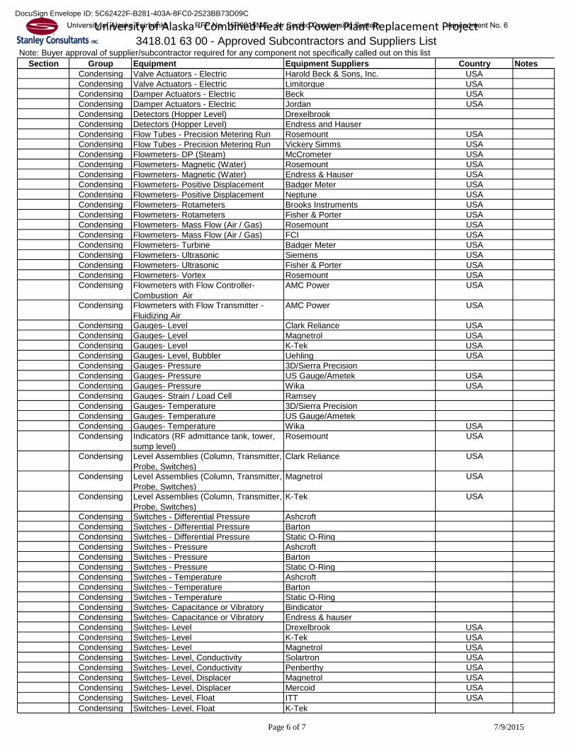
Note: Buyer approval of supplier/subcontractor required for any component not specifically called out on this listSection Group Equipment Equipment Suppliers Country Notes
All Any equipment or product Bidder or wholly owned subsidiaryCondensing 480V MCC Allen BradleyCondensing 480V MCC Cutler-HammerCondensing 480V MCC General ElectricCondensing 480V MCC SiemensCondensing 480V MCC Square DCondensing Air Filters- Compressed Air Hankinson USACondensing Air Filters- Instrument (& Regulators) FisherCondensing Air Filters- Instrument (& Regulators) NorgrenCondensing Air Filters- Instrument (& Regulators) WilkersonCondensing Coatings AmeronCondensing Coatings CarbolineCondensing Coatings DevoeCondensing Coatings InternationalCondensing Coatings JolanCondensing Coatings Keeler & LongCondensing Coatings PPGCondensing Coatings Sherwin WilliamsCondensing Coatings SigmeCondensing Coatings TenemecCondensing Code Pipe Fab BendtecCondensing Code Pipe Fab BoccardCondensing Code Pipe Fab IPSCondensing Code Pipe Fab J.F. AhernCondensing Code Pipe Fab KelgorCondensing Code Pipe Fab ScottCondensing Code Pipe Fab SCPICCondensing Code Pipe Fab ShawCondensing Code Pipe Fab SuncoCondensing Code Pipe Fab TeamCondensing Code Pipe Fab TMRPCondensing Control Panels Control Engineering Company USACondensing Control Panels Hoffman Engineering Company USACondensing Control Panels Rittal USACondensing Dampers Advanced Valve Design USACondensing Dampers Bachman Dampjoint Inc. CANADACondensing Dampers Bachman USA USACondensing Dampers Barron Ind. USACondensing Dampers Control Equip. Co. USACondensing Dampers Damper Design Inc. USACondensing Dampers Effox Inc. USACondensing Dampers Flexton CANADACondensing Dampers Fox Equipment USACondensing Dampers Fritsch Power & Processing Services USACondensing Dampers MaderCondensing Dampers TLT Babcock USACondensing Dampers Wahlco Metroflex USACondensing Drives – Variable Speed, 600V and
BelowABB USA
Condensing Drives – Variable Speed, 600V and Below
Allen Bradley USA
Condensing Drives – Variable Speed, 600V and Below
WEG
Condensing Drives – Variable Speed, 600V and Below
Yaskawa
Condensing Drives – Variable Speed, 600V and Below
Hyundai Heavy Industries
Condensing Duct and Flue Slide Plates (Sliding Bearing Plates)
American Bearings USA
Condensing Duct and Flue Slide Plates (Sliding Bearing Plates)
Amscot USA
Condensing Duct and Flue Slide Plates (Sliding Bearing Plates)
Merriman, Inc. USA
3418.01 63 00 - Approved Subcontractors and Suppliers ListUniversity of Alaska - Combined Heat and Power Plant Replacement ProjectUniversity of Alaska Fairbanks RFP No. 15P0015MG - Air Cooled Condensing System Amendment No. 6
Note: Buyer approval of supplier/subcontractor required for any component not specifically called out on this listSection Group Equipment Equipment Suppliers Country Notes
3418.01 63 00 - Approved Subcontractors and Suppliers ListUniversity of Alaska - Combined Heat and Power Plant Replacement Project
Condensing Duct and Flue Slide Plates (Sliding Bearing Plates)
Condensing Fuse Gould Shawmut USACondensing Gearboxes Rexnord / Faulk USACondensing Gearboxes Siemens / Flender GermanyCondensing Gearboxes GE O&G / Lufkin USACondensing Gearboxes Voith GermanyCondensing Gearboxes Allen Gears UKCondensing Gearboxes Renk - Maag SwitzerlandCondensing Heat Tracing- Electrical Chromalox USACondensing Heat Tracing- Electrical Raychem USACondensing Heat Tracing- Electrical Thermon USACondensing Heat Tracing- Electrical Tyco USACondensing Instrument Valve Manifolds Anderson Greenwood CompanyCondensing Instrument Valve Manifolds EmersonCondensing Instrument Valve Manifolds PGICondensing Instrument Valve Manifolds RosemountCondensing Instrument Valve Manifolds SwagelokCondensing Integral Valve Position Indicators AutomaxCondensing Integral Valve Position Indicators BettiswitchCondensing Integral Valve Position Indicators StonelCondensing Integral Valve Position Indicators TriacCondensing Integral Valve Position Indicators WestlockCondensing Motors US Electrical MotorsCondensing Motors- Low Voltage ABB USACondensing Motors- Low Voltage General Electric USACondensing Motors- Low Voltage Hitachi JapanCondensing Motors- Low Voltage Reliance USACondensing Motors- Low Voltage Siemens USACondensing Motors- Low Voltage TECO Westinghouse USACondensing Motors- Low Voltage Toshiba Mitsubishi- Electric JapanCondensing Motors- Low Voltage WEG BRAZILCondensing Motors- Medium Voltage ABB USACondensing Motors- Medium Voltage General Electric BRAZILCondensing Motors- Medium Voltage Hitachi JAPANCondensing Motors- Medium Voltage Hyundai KoreaCondensing Motors- Medium Voltage Reliance USACondensing Motors- Medium Voltage Siemens USACondensing Motors- Medium Voltage TECO/Westinghouse USA/TAIWANCondensing Motors- Medium Voltage Toshiba JAPANCondensing Motors- Medium Voltage WEG BRAZILCondensing Pipe Hangers and Support Anvil International (Grinnell) USACondensing Pipe Hangers and Support Atlas Ideal Metals USACondensing Pipe Hangers and Support Basic Engineers USACondensing Pipe Hangers and Support Bergen Power Pipe Supports USACondensing Pipe Hangers and Support Binder USA
University of Alaska Fairbanks RFP No. 15P0015MG - Air Cooled Condensing System Amendment No. 6DocuSign Envelope ID: 5C62422F-B281-403A-8FC0-2523BB73D09C
Page 3 of 7 7/9/2015
Note: Buyer approval of supplier/subcontractor required for any component not specifically called out on this listSection Group Equipment Equipment Suppliers Country Notes
3418.01 63 00 - Approved Subcontractors and Suppliers ListUniversity of Alaska - Combined Heat and Power Plant Replacement Project
Condensing Pipe Hangers and Support Lisega USACondensing Pipe Hangers and Support Mitsubishi Steel Mfg. Co., Ltd. JAPANCondensing Pipe Hangers and Support Mueller Flow Control USACondensing Pipe Hangers and Support PHS Industries USACondensing Pipe Hangers and Support Pipe Support Ltd. USACondensing Pipe Hangers and Support Piping Technology USACondensing Pipe Hangers and Support Sanway Tekki JAPANCondensing Pipe Hangers and Support SHAW USACondensing Pipe Hangers and Support Yamashita Seisakusyo JAPANCondensing Pipe Supports (Spring) Anvil International (Grinnell) USACondensing Pipe Supports (Spring) Basic Engineers USACondensing Pipe Supports (Spring) Bergen Power USACondensing Pipe Supports (Spring) Lisega USACondensing Pipe Supports (Spring) Piping Technologies USACondensing Piping- Fabrication (Metal) Bendtec Inc. USACondensing Piping- Fabrication (Metal) DMI USACondensing Piping- Fabrication (Metal) Globe Mechanical USACondensing Piping- Fabrication (Metal) JF Ahern USACondensing Piping- Fabrication (Metal) Shaw Group, Inc. USACondensing Piping- Fabrication (Metal) Team Industries USACondensing Piping- Fabrication (Metal) TURNER INDUSTRIES USACondensing Process Heaters ChromaloxCondensing Process Heaters GaumerCondensing Process Heaters WatlowCondensing Pumps- Vacuum Gardner Denver NashCondensing Pumps- Vacuum VoonerCondensing Pumps- Vacuum FriatecCondensing Pumps- Vacuum DekkerCondensing Pumps- Vacuum Lyco WausauCondensing Pumps- Vacuum WintekCondensing Pumps- Vacuum NitechCondensing Pumps- Vacuum KerrCondensing Relays - General Purpose Allen Bradley USACondensing Relays - General Purpose Cutler-Hammer USACondensing Relays - General Purpose General Electric USACondensing Relays - General Purpose Potter-Brumfield USACondensing Relays- Auxiliary Control Allen Bradley USACondensing Relays- Auxiliary Control Diversified Electronics USACondensing Relays- Auxiliary Control General Electric USACondensing Relays- Auxiliary Control Potter Brumfeld USACondensing Relays- Auxiliary Control Square D USACondensing Relays- Auxiliary Control Westinghouse USACondensing Silencers (Safety Valves) BEPMCondensing Silencers (Safety Valves) Burgess ManningCondensing Silencers (Safety Valves) CCI/Fluid KineticsCondensing Silencers (Safety Valves) MaximCondensing Silencers (Safety Valves) QuietfloCondensing Terminal Blocks Allen Bradley USACondensing Terminal Blocks Marathon USACondensing Terminal Blocks Marathon USACondensing Terminal Blocks PhoenixCondensing Transducers (electrical) GE USACondensing Transducers (electrical) Moore Industries USACondensing Transducers (electrical) Rochester Instruments USACondensing Transducers (electrical) Scientific Columbus USACondensing Transducers (electrical) Transdata USACondensing Transducers- Frequency Scientific Columbus USACondensing Transducers, Watt Scientific Columbus USACondensing Tube Fittings Parker USACondensing Tube Fittings Swagelok USACondensing Tube Fittings Whitey USACondensing Valves- Ball Apollo USACondensing Valves- Ball CopelandCondensing Valves- Ball Mogas USA
University of Alaska Fairbanks RFP No. 15P0015MG - Air Cooled Condensing System Amendment No. 6DocuSign Envelope ID: 5C62422F-B281-403A-8FC0-2523BB73D09C
Page 4 of 7 7/9/2015
Note: Buyer approval of supplier/subcontractor required for any component not specifically called out on this listSection Group Equipment Equipment Suppliers Country Notes
3418.01 63 00 - Approved Subcontractors and Suppliers ListUniversity of Alaska - Combined Heat and Power Plant Replacement Project
Condensing Valves- Ball Neles- Jamesbury USACondensing Valves- Ball Parker USACondensing Valves- Ball PowellCondensing Valves- Ball Severe Service Technologies c/o Power
University of Alaska Fairbanks RFP No. 15P0015MG - Air Cooled Condensing System Amendment No. 6DocuSign Envelope ID: 5C62422F-B281-403A-8FC0-2523BB73D09C
Page 5 of 7 7/9/2015
Note: Buyer approval of supplier/subcontractor required for any component not specifically called out on this listSection Group Equipment Equipment Suppliers Country Notes
3418.01 63 00 - Approved Subcontractors and Suppliers ListUniversity of Alaska - Combined Heat and Power Plant Replacement Project
Condensing Valves- Forged Steel Whitey USACondensing Valves- Forged Steel Yarway USACondensing Valves- High Pressure Cast Steel Anchor Darling USACondensing Valves- High Pressure Cast Steel Bonney Forge USACondensing Valves- High Pressure Cast Steel Crane Pacific Valves USACondensing Valves- High Pressure Cast Steel Dewrance USACondensing Valves- High Pressure Cast Steel Edward/Vogt (Flowserve) USACondensing Valves- High Pressure Cast Steel Flowserve Edward USACondensing Valves- High Pressure Cast Steel Karatsu Valve Co., Ltd. JAPANCondensing Valves- High Pressure Cast Steel Pacific/Crane USACondensing Valves- High Pressure Cast Steel Powell USACondensing Valves- High Pressure Cast Steel Tyco Valve Co. USA/CANCondensing Valves- High Pressure Cast Steel Tyco Valves & Controls USACondensing Valves- High Pressure Cast Steel Utsue Valves Co., Ltd. JAPANCondensing Valves- High Pressure Cast Steel Valvetechnologies USACondensing Valves- High Pressure Cast Steel Velan CAN/USACondensing Valves- High Pressure Cast Steel Velan Valve Corporation USACondensing Valves- High Pressure Cast Steel Weir Valves & Controls USA USACondensing Valves- Insert Type and Other Stop &
CheckCrane
Condensing Valves- Insert Type and Other Stop & Check
Duo Check
Condensing Valves- Insert Type and Other Stop & Check
Karatsu Valve Co. Ltd. JAPAN
Condensing Valves- Insert Type and Other Stop & Check
Keystone/Anderson Greenwood USA
Condensing Valves- Insert Type and Other Stop & Check
Marlin
Condensing Valves- Insert Type and Other Stop & Check
Power & Process (Technocheck) USA
Condensing Valves- Insert Type and Other Stop & Check
Tyco Valve Co. USA/CAN
Condensing Valves- Insert Type and Other Stop & Check
Velan
Condensing Valves- Insert Type and Other Stop & Check
Weir USA
Condensing Valves- Instrument Anderson Greenwood CompanyCondensing Valves- Instrument Swagelok USACondensing Valves- Instrument Whitey USACondensing Valves- Plug DeZurik USACondensing Valves- Plug Duriron/Durco USACondensing Valves- Plug Keystone USACondensing Valves- Plug Newcon USACondensing Valves- Plug Nordstrom/Tufline (Division of Xomox) USACondensing Valves- Plug Velan USA/CANCondensing Valves- Safety Relief Lonegran (Tyco) USACondensing Valves- Safety Relief Tyco (Crosby)Condensing Valves- Safety Relief Vickers (Eaton) USACondensing Valves- Severe Service Ball Control Components Inc - Sulzer USACondensing Valves- Severe Service Ball Crane USACondensing Valves- Severe Service Ball Fisher Control USACondensing Valves- Severe Service Ball Flowserve USACondensing Valves- Severe Service Ball Mogas USACondensing Valves- Severe Service Ball SPX Process Equipment (Copes
Vulcan)USA
Condensing Valves- Severe Service Ball Valve Technologies USACondensing Valves- Severe Service Ball Velan USACondensing Valves- Severe Service Ball Yarway USACondensing Valves- Solenoid ASCO USACondensing Valves- Solenoid Stonel USACondensing Valves- Tilting Disc Check Anchor/Darling (Flowserve) USACondensing Valves- Tilting Disc Check Atwood & Morrill USACondensing Valves- Tilting Disc Check Edwards USACondensing Valve Actuators - Electric EIM (Emerson)
University of Alaska Fairbanks RFP No. 15P0015MG - Air Cooled Condensing System Amendment No. 6DocuSign Envelope ID: 5C62422F-B281-403A-8FC0-2523BB73D09C
Page 6 of 7 7/9/2015
Note: Buyer approval of supplier/subcontractor required for any component not specifically called out on this listSection Group Equipment Equipment Suppliers Country Notes
3418.01 63 00 - Approved Subcontractors and Suppliers ListUniversity of Alaska - Combined Heat and Power Plant Replacement Project
Condensing Valve Actuators - Electric Harold Beck & Sons, Inc. USACondensing Valve Actuators - Electric Limitorque USACondensing Damper Actuators - Electric Beck USACondensing Damper Actuators - Electric Jordan USACondensing Detectors (Hopper Level) DrexelbrookCondensing Detectors (Hopper Level) Endress and HauserCondensing Flow Tubes - Precision Metering Run Rosemount USACondensing Flow Tubes - Precision Metering Run Vickery Simms USACondensing Flowmeters- DP (Steam) McCrometer USACondensing Flowmeters- Magnetic (Water) Rosemount USACondensing Flowmeters- Magnetic (Water) Endress & Hauser USACondensing Flowmeters- Positive Displacement Badger Meter USACondensing Flowmeters- Positive Displacement Neptune USACondensing Flowmeters- Rotameters Brooks Instruments USACondensing Flowmeters- Rotameters Fisher & Porter USACondensing Flowmeters- Mass Flow (Air / Gas) Rosemount USACondensing Flowmeters- Mass Flow (Air / Gas) FCI USACondensing Flowmeters- Turbine Badger Meter USACondensing Flowmeters- Ultrasonic Siemens USACondensing Flowmeters- Ultrasonic Fisher & Porter USACondensing Flowmeters- Vortex Rosemount USACondensing Flowmeters with Flow Controller-
Combustion Air AMC Power USA
Condensing Flowmeters with Flow Transmitter - Fluidizing Air
AMC Power USA
Condensing Gauges- Level Clark Reliance USACondensing Gauges- Level Magnetrol USACondensing Gauges- Level K-Tek USACondensing Gauges- Level, Bubbler Uehling USACondensing Gauges- Pressure 3D/Sierra PrecisionCondensing Gauges- Pressure US Gauge/Ametek USACondensing Gauges- Pressure Wika USACondensing Gauges- Strain / Load Cell RamseyCondensing Gauges- Temperature 3D/Sierra PrecisionCondensing Gauges- Temperature US Gauge/AmetekCondensing Gauges- Temperature Wika USACondensing Indicators (RF admittance tank, tower,
University of Alaska Fairbanks RFP No. 15P0015MG - Air Cooled Condensing System Amendment No. 6DocuSign Envelope ID: 5C62422F-B281-403A-8FC0-2523BB73D09C
Page 7 of 7 7/9/2015
Note: Buyer approval of supplier/subcontractor required for any component not specifically called out on this listSection Group Equipment Equipment Suppliers Country Notes
3418.01 63 00 - Approved Subcontractors and Suppliers ListUniversity of Alaska - Combined Heat and Power Plant Replacement Project
University of Alaska Fairbanks RFP No. 15P0015MG - Air Cooled Condensing System Amendment No. 6DocuSign Envelope ID: 5C62422F-B281-403A-8FC0-2523BB73D09C
A. NOTE TO BIDDERS: With the exception of condensing system operational, performance, and reliability requirements, this section should be considered preliminary. Final test procedures will be negotiated after notice of intent to award.
B. The requirements presented in this section shall establish the basis of design and required thermal and operational performance for all equipment provided under this Contract while being operated as a single complete system. Unless otherwise noted in the individual equipment sections, the Seller shall determine the basis of design and required performance of individual pieces of equipment such that the requirements of this section are met during normal operation.
C. Seller shall provide a detailed write-up explaining the operation of the ACC for freeze protection down to the extreme temperature listed in Section 00 43 33 that encompasses the load ranges provided in Paragraph 1.03 A.
D. All operating conditions and thermal performance guarantees are contained in section Section 00 43 33 – Proposed Products Form. All point value guarantees shall be based on steady load conditions.
E. Conditions of system inputs provided by the Buyer are located in Paragraph 1.04 of this Section. The information provided shall form the basis from which the Seller shall develop the proposed guarantees.
1.02 BASIS OF DESIGN AND PERFORMANCE
A. Design condensing system, including ACC, surface condenser and associated equipment included in this Contract to operate at the guaranteed operating values for the guaranteed operating conditions can be found in the Guarantees Section 00 43 33.
B. The condensing system performance guarantees identified in Section 00 43 33 shall be based upon the use of circulating water quality and steam turbine exhaust conditions as identified in this Section, as well as Sections 00 43 33, 48 11 16, and 48 12 17.
C. The equipment shall be capable of operating at any point over the entire load range of the steam turbine and under any ambient conditions.
1.03 OPERATIONAL REQUIREMENTS
A. Operational Range: 10% to 100% of maximum turbine exhaust energy as defined below 1. Maximum Turbine Exhaust Energy: As defined in the Guarantees included in Section 00 43 33. 2. Minimum Continuous Load: 10% of maximum turbine exhaust energy.
B. Meet the following operational requirements over the entire operational range of the steam turbine. 1. Design ACC to maintain turbine exhaust pressure of 10 inchesHg at an ambient temperature of
93°F without the use of the surface condenser. 2. Design ACC to maintain turbine exhaust pressure of 4 inchesHg at an ambient temperature of
40°F without the use of the surface condenser. 3. Design ACC to maintain turbine exhaust pressure no lower than 2 inchesHg under any ambient
conditions between 40°F and the and the extreme ambient low temperature. 4. The ACC must be capable of continuous operation without internal or external ice buildup
(freezing) by incorporation of various design features such as fan speed variation, sectionalizing (steam isolation valves), isolation from the ambient environment (louvers), and air recirculation.
Rev. 0
University of Alaska Fairbanks RFP No. 15P0015MG - Air Cooled Condensing System Amendment No. 6DocuSign Envelope ID: 5C62422F-B281-403A-8FC0-2523BB73D09C
5. The control logic should be designed to maintain the backpressure by optimizing the fan speed for the ambient conditions and the steam turbine exhaust energy. The control logic shall also automatically protect the system from freezing by varying fan speed, isolating cells, or closing louvers.
1.04 BASIS OF PERFORMANCE GUARANTEES
A. TURBINBE EXHAUST ENERGY 1. As defined in Section 00 43 33.
B. INSTRUMENT AIR 1. The Buyer shall supply adequate instrument air at the following conditions:
a. Supply Pressure: 80-125 psig b. Dew Point: -40.0 °F c. Compressor Type: As required by Seller
1.05 TUNING PERIOD
A. The Seller shall be afforded 30 calendar days to allow for condensing system performance adjustments (tuning) prior to the start of testing.
B. The tuning period may be extended upon request of the Seller and at the discretion of the Buyer.
C. The tuning period shall end no later than 21 calendar days prior to an emissions testing deadline mandated by the Air Permit or any applicable state or federal statutes.
D. The tuning period will be used to check equipment operation and functionality and make any modifications necessary prior to guarantee testing.
1.06 CONDENSING SYSTEM DEMONSTRATION
A. Demonstration will occur during the start-up and commissioning period of the project.
B. Seller shall demonstrate that the equipment provided can meet the Operational Requirements set forth in Paragraph 1.03 of this Section.
C. Seller shall demonstrate that the equipment provided can operate during automatic transitions between ACC freeze protection modes.
D. Seller shall demonstrate the opening and closing of the freeze protection devices.
1.07 PERFORMANCE TESTS
A. Performance testing will consist of: 1. Steam generator performance test 2. Condensing system pressure test 3. Auxiliary power consumption test
B. General Requirements for all performance testing 1. Plant instrumentation will be utilized to the greatest extent possible while still maintaining an
acceptable test uncertainty or tolerance. 2. The Buyer and Seller shall agree to a calibration procedure prior to testing. 3. All performance tests shall be executed by Buyer or a buyer supplied independent third party
(experienced in such work and mutually acceptable to Buyer and Seller). 4. Buyer will notify Seller in writing at least two (2) weeks prior to the scheduled performance test
date. It shall be Seller's responsibility to furnish a test observer on the scheduled date. 5. If any individual performance test identified in 1.07.A requires a retest, it may be run separately.
Rev. 0
University of Alaska Fairbanks RFP No. 15P0015MG - Air Cooled Condensing System Amendment No. 6DocuSign Envelope ID: 5C62422F-B281-403A-8FC0-2523BB73D09C
6. The Seller's representative shall act in an advisory capacity and shall have access to all pertinent test records at all times. Any performance test(s) shall be conducted in a manner to satisfy the Seller that the specified performance conditions are being maintained.
7. The equipment supplied by Seller shall be operated and maintained according to Seller's guidelines, good engineering and operating principles and Seller's Maintenance and Operating manual, both prior to and during the performance testing. The Seller shall not be responsible for the deterioration or failure of any equipment resulting from improper maintenance and operation or the failure to observe applicable O&M instructions and written recommendations of the Seller and its subvendors.
C. Initial condensing system performance tests will be run concurrently with performance testing of other major equipment. Availability test may not be run concurrently with performance tests.
D. The performance guarantees are subject to the following provisions: 1. All replacement parts shall be of Seller's manufacture or supply, unless in Seller's judgment
parts supplied by others are of equal or superior quality.
E. Buyer will provide Seller with copies of the final test report, including all raw data in electronic format, within two (2) months of the conclusion of the performance testing.
F. The equipment shall be started-up in presence of a Seller Service Representative. Immediately prior to testing, the equipment shall be operated at a constant rating for a period that is sufficient to demonstrate steady state operation, based upon steam turbine exhaust output. Steady state conditions shall be maintained during the test period.
G. The duration of the test period shall be the minimum required for obtaining representative data but shall not be less than 4 hours.
H. Buyer will utilize the plant historian to record pertinent data collected by the plant DCS. Buyer or third party testing firm will provide and maintain any temporary instrumentation and data logging equipment necessary to obtain additional test data. Buyer will also maintain equipment maintenance logs necessary to monitor operation, from the initial equipment start-up date through the final performance-testing period.
I. All process streams shall be sampled or measured simultaneously.
J. Test tolerance, unless agreed to by all parties due to deviation from ASME PTC test methods, will not be applied to corrected test results prior to comparison to guaranteed values.
K. The procedures described in ASME PTC 12.2, PTC 24 and PTC 30.1 may be modified by mutual agreement of all parties to minimize complexity and cost while maintaining an acceptable test certainty. Should the parties be unable to agree on modifications of the performance test codes, the test shall be conducted in accordance with the test codes with the exception that existing plant instrumentation will be utilized to every extent possible.
L. Auxiliary Power Consumption Test: 1. The auxiliary power consumption will be measured during quantity of four one hour long
performance test periods. Auxiliary power will be measured by summing the power consumption of the equipment listed below using either station and/or portable measurement equipment of reasonable accuracy that has been calibrated within the last year.
2. The auxiliary power consumption shall be recorded for the following equipment: a. Air Cooled Condenser Fans b. Vacuum Pumps c. Any other equipment supplied by Seller that is rated at 5 HP or larger and is in continuous use during normal condensing system operation. Where power consumption instrumentation is not provided as a part of the plant design, the Buyer shall furnish temporary instrumentation to collect the necessary data.
3. The power consumption is to be determined at the motor inlet, or other affected device leads.
Rev. 0
University of Alaska Fairbanks RFP No. 15P0015MG - Air Cooled Condensing System Amendment No. 6DocuSign Envelope ID: 5C62422F-B281-403A-8FC0-2523BB73D09C
4. Applicable ASME PTCs shall be used as general guidelines to develop the detailed test procedures.
M. Steam Consumption Test: 1. The auxiliary steam consumption will be measured during quantity of four fifteen minute long
performance test periods. Steam consumption will be measured in accordance with ASME PTC 24.
2. The steam consumption shall be recorded for the following equipment: a. Steam Jet Air Ejector (SJAE) (Holding)
3. ASME PTC 24 shall be used as a general guideline to develop the detailed test procedure.
N. Performance tests and performance calculations shall be made in accordance with the codes and procedures identified in this section or other mutually agreed upon methods in effect as of the original date of the proposal submittal, and the measure of performance shall be the results of such tests. The guaranteed values as stated in Section 00 43 33 are contingent upon measurement in accordance with the following test procedures: 1. Condensing System
a. ASME PTC 12.2 2010 (Steam Surface Condenser) b. ASME PTC 30.1 2007 (Air-Cooled Steam Condensers) c. ASME PTC 24 (Ejectors)a d.
2. Steam Properties a. "Thermodynamic Properties of Steam" per the 1997 ASME Steam Tables
O. Test Corrections 1. Test corrections will be conducted as specified by the applicable PTC
1.08 ADDITIONAL CONSIDERATIONS
A. Should the condensing system performance be limited by equipment outside of the Sellers scope of supply such that the condensing system is not able to reach the guaranteed conditions, the Buyer, at their option, may choose one of the following: 1. Waive any further testing and accept the condensing system performance as is 2. Postpone any further testing until the underperforming equipment can be repaired. Subsequent
condensing system performance testing will be at the Buyers expense and shall be limited to a single retest. The guarantees shall be deemed to be met should the condensing system fail to achieve the guaranteed conditions due to limitations caused by the Buyers equipment upon retest.
PART 2 PRODUCTS NOT USED
PART 3 EXECUTION NOT USED
END OF SECTION 1) R. Hernandez 2) J. Solan
Rev. 0
University of Alaska Fairbanks RFP No. 15P0015MG - Air Cooled Condensing System Amendment No. 6DocuSign Envelope ID: 5C62422F-B281-403A-8FC0-2523BB73D09C
23875.20.1025672.10.00 LOW VOLTAGE VARIABLE FREQUENCY DRIVES dv126 SECTION 3418.26 29 23 - Page 1
PART 1 GENERAL
1.01 SECTION INCLUDES
A. Low-voltage variable frequency drive (VFD) designed for use on 3-phase squirrel cage induction motor.
1.02 ACTION SUBMITTALS
A. Drawings: 1. Certified outline, general arrangement, assembly, and installation drawings, that includes front
view, dimensions, and weight. 2. Elementary diagrams (3-line diagrams) and schematic control diagrams of complete VFD system
showing terminal block terminations, device terminal numbers and internal wiring diagrams. 3. Certified drawings of cable termination compartments showing preferred locations for conduit
entry/exit locations and indicating space available for cable terminations. 4. Nameplate drawing.
1.03 CLOSEOUT SUBMITTALS
A. Operation and maintenance manuals. Refer to section 01 78 23. Provide, at minimum: 1. Final copies of documents listed above. 2. Operating and maintenance procedures. 3. Spare parts lists with pricing. 4. Installation field reports and Data Sheets updated to reflect field installation conditions 5. Copies of warranty.
1.04 QUALITY ASSURANCE
A. Design and manufacture according to latest editions of applicable NEMA, UL, NFPA, IEEE, and ANSI standards.
B. Manufacturer shall be ISO 9001 certified and shall have produced similar electrical equipment for minimum period of 5 years.
C. When requested by Engineer, provide acceptable list of similar equipment installations complying with requirements of this specification.
D. Completed drive shall be tested for at least 3 hours with induction motor connected.
1.05 DELIVERY, STORAGE, AND HANDLING
A. During delivery and storage, handle equipment to prevent damage, denting, or scoring.
B. Store equipment and components in clean, dry place. Protect from weather, dirt, water, construction debris, and physical damage in accordance with manufacturer’s instructions.
1.06 REDUNDANCY
A. Provide two identical (redundant) VFDs for any single-redundant piece of major equipment requiring variable speed drives. This includes, but is not limited to, the following: Primary Air Fans, Secondary Air Fans, Induced Draft Fans.
PART 2 PRODUCTS
2.01 MANUFACTURERS
Rev. 0
University of Alaska Fairbanks RFP No. 15P0015MG - Air Cooled Condensing System Amendment No. 6DocuSign Envelope ID: 5C62422F-B281-403A-8FC0-2523BB73D09C
23875.20.1025672.10.00 LOW VOLTAGE VARIABLE FREQUENCY DRIVES dv126 SECTION 3418.26 29 23 - Page 2
A. Reference Section 01 63 00 – Approved Subcontractors and Suppliers List
B. All Primary Air, Secondary Air, and Induced Draft fan VFDs supplied under this contract shall be provided by the same equipment manufacturer and product line.
C. Manufacturers of VFDs supplied by equipment sub-vendors shall be in accordance with 01 63 00.
2.02 SYSTEM DESCRIPTION
A. VFD shall convert incoming fixed frequency 3-phase ac power into variable frequency and voltage for controlling speed of 3-phase ac motor.
B. Motor voltage shall be varied with frequency to maintain desired motor magnetization current suitable for eliminating need for motor derating.
C. VFD shall be sinusoidal PWM type drive with sensor-less torque vector control capability. Control techniques other than PWM, not acceptable.
D. Components: 1. Full-wave diode rectifier to convert supply ac to fixed dc voltage. Minimum 18 pulse rectifier. 2. Dc link capacitors. 3. Insulated Gate Bipolar Transistor (IGBT) power section, dual rated for either variable or constant
torque applications. 4. VFD shall be microprocessor-based with LED and LCD display to monitor operating conditions. 5. Separate control and power terminal boards.
E. VFD shall be of modular construction for ease of access to control and power wiring, and maintenance.
F. Provide in NEMA 1 enclosure for use in normal, nonhazardous industrial environment.
G. Enclosure doors shall include electromechanical interlocking system with safety switch and electrical interlocks tied to main breaker. Whenever doors are open, safety ground switch shall connect plus, minus, and neutral dc buses to ground to ensure stored energy is discharged.
2.03 DESIGN REQUIREMENTS
A. Where manufacturer determines an input drive transformer, input filter, or output filter is required to meet installation requirements, they shall also be provided.
B. Point of Common Coupling (PCC) shall be defined as terminals on input side of circuit breaker directly feeding each individual drive.
C. Total Harmonic Distortion (THD) at each PCC shall not exceed 5%, as recommended for General Systems as listed in Table 10.2 of IEEE Standard 519.
D. Harmonic current distortion at PCC shall not exceed limits listed in Table 10.3 of IEEE Standard 519.
E. Design drive to provide 50,000 hours mean time between failures (MTBF) when specified preventative maintenance is performed.
F. Design motors furnished to meet NEMA MG1, Part 31 for VFD service.
G. Symbols shall conform to ANSI Y32.2/IEEE 315/CSA Z99.
H. Printed circuit boards shall be completely tested and burned-in, in accordance with UL347A before being assembled into completed VFD.
Rev. 0
University of Alaska Fairbanks RFP No. 15P0015MG - Air Cooled Condensing System Amendment No. 6DocuSign Envelope ID: 5C62422F-B281-403A-8FC0-2523BB73D09C
23875.20.1025672.10.00 LOW VOLTAGE VARIABLE FREQUENCY DRIVES dv126 SECTION 3418.26 29 23 - Page 3
I. Design equipment in accordance with seismic requirements listed in most recent local building codes and Data Sheets.
2.04 MECHANICAL CONSTRUCTION
A. Provide recommendation for attachment of equipment to foundation or structural supports with design drawings, as applicable. Method of attachment will take into account seismic requirements of job site as indicated on Data Sheets.
2.05 INPUT POWER
A. System shall be capable of maintaining rated torque and speed with bus voltage deviations of ±10% and frequency deviations of ±5%.
B. Line notching, transients, and harmonics on incoming line shall not affect VFD performance.
C. Below 70% bus voltage, motor will be allowed to coast. If bus voltage is restored within 2 seconds, system can be started, if selected. If bus voltage is not restored within 2 seconds, system shall be automatically shut down. Automatic or manual restart shall be selectable from control panel.
D. VFD shall have provisions for input line reactor to be incorporated into VFD enclosure.
E. Drive efficiency shall be 95% or higher at rated load.
2.06 OUTPUT POWER
A. Operating mode: 1. Frequency at 60 Hz and below: Constant volts per Hz mode. 2. Above 60 Hz: Selectively operate in either constant volts per Hz mode or constant voltage
extended frequency mode.
B. Rated output voltage: Programmable for either 80 to 240 volts or from 320 to 480 volts depending on 3-phase motor nameplate rating.
C. VFD shall be capable of minimum of 110% of rated full-load current in continuous operation, in accordance with NEC Table 430.150.
2.07 OPERATING RANGE
A. Speed range: 6 to 60 Hz. Both minimum and maximum speeds shall be field-adjustable.
B. VFD shall not have electrical resonance within operating speed range.
C. VFD shall be able to speed search and immediately pick up spinning motor in either forward or reverse direction.
2.08 TORSIONAL REQUIREMENTS
A. VFD, motor, and equipment load shall not develop adverse speed dependent oscillations.
2.09 NOISE
A. Drive shall not cause motor audible noise to increase more than 3 dB at 3' (1 m) above rated noise level for operation on full voltage starter.
2.10 MINIMUM DISPLACEMENT POWER FACTOR
Rev. 0
University of Alaska Fairbanks RFP No. 15P0015MG - Air Cooled Condensing System Amendment No. 6DocuSign Envelope ID: 5C62422F-B281-403A-8FC0-2523BB73D09C
23875.20.1025672.10.00 LOW VOLTAGE VARIABLE FREQUENCY DRIVES dv126 SECTION 3418.26 29 23 - Page 4
A. PF 0.90 lagging, or higher, at any speed or load without use of power factor correction capacitors.
2.11 HARMONICS MITIGATION
A. Provide output filters or line reactors, as required, such that motor insulation will not be damaged.
B. If additional equipment is necessary to meet IEEE 519 requirements, it shall be through use of one or more of following: 1. Input isolation transformer. 2. Input line reactor. 3. Input harmonic trap filter with series reactor. 4. Higher pulse rectifier. 5. Mirus filter. 6. Dc link reactor.
C. Drive manufacturer shall select and approve equipment provided.
2.12 DRIVE CONTROL
A. VFD shall use control strategy that maximizes efficiency, performance, and power factor while minimizing motor heating.
B. Drive regulator and control: Digital microprocessor design with following functions: 1. Speed regulation. 2. Current regulation. 3. Load angle regulation. 4. Drive protection. 5. Drive diagnostics. 6. System sequencing.
C. VFD regulator and control functions shall be stored on nonvolatile memory.
D. Drive shall have minimum of 3 programmable prohibited frequency ranges with adjustable span of 0 to 10 Hz.
E. Provide drive with local and remote controls: 1. Locate 2-position maintained switch on front of enclosure for selection of “Local” or “Remote”
control. 2. Individual momentary buttons for “Local,” “Start,” and “Stop.” 3. Speed reference potentiometer.
F. Operation: 1. Switch in “Local” position: Drive shall operate at speed set by potentiometer when local “Start”
button is pushed. “Stop” button shall stop equipment without delay. 2. Switch in “Remote” position: Drive shall be remotely controlled. Local potentiometer, “Start”
button, and “Stop” button shall have no effect on operation. a. Speed control shall regulate motor speed corresponding to remote speed signal. b. When incoming signal is varying, rate of change of motor speed shall be limited by pre-
selected acceleration/ deceleration rate. c. Drive shall be programmable to either run at constant speed as determined by minimum
speed setting, last signal, preset speed, or to shut down, upon loss of speed signal. Remote speed signal falling below lower limit of range shall also be considered as loss of speed signal. Loss of remote speed signal shall be alarmed.
d. If remote speed signal is above range upper limit, drive shall run at speed corresponding to upper limit.
e. Alarms and indication: 1) Loss of remote speed signal shall be alarmed. 2) Drive failure alarm.
Rev. 0
University of Alaska Fairbanks RFP No. 15P0015MG - Air Cooled Condensing System Amendment No. 6DocuSign Envelope ID: 5C62422F-B281-403A-8FC0-2523BB73D09C
23875.20.1025672.10.00 LOW VOLTAGE VARIABLE FREQUENCY DRIVES dv126 SECTION 3418.26 29 23 - Page 5
3) Drive fault alarm. 4) Drive in remote and local control indication. 5) Drive running indication.
G. Following shall be available locally either on control panel display or by use of readouts and LEDs, and remotely through communication interface: 1. Drive ready. 2. Drive running. 3. Current, amps. 4. Line-line voltage, volts. 5. Output horsepower, hp. 6. Speed, rpm. 7. Frequency, Hz: Digital readout. 8. Drive alarm conditions.
a. Missing run or start permissive. b. Low control voltage. c. Microprocessor problem. d. I/O addressing problem. e. Loss of speed reference. f. Common trouble alarm.
9. Drive fault conditions requiring immediate attention, and may indicate impending shutdown of drive. a. Source undervoltage. b. Source overvoltage. c. Source loss of phase. d. Source reverse phase sequence. e. Load overcurrent. f. Overspeed. g. Ground fault. h. Dc Link overvoltage.
H. Provide communications interface for remote monitoring and control of VFD using DeviceNet communications protocol.
2.13 DRIVE DIAGNOSTICS
A. Provide comprehensive diagnostics for maintenance and troubleshooting including: 1. Self-test of microprocessor drive control system. 2. LED indicators for status indication on control boards. 3. Convenient maintenance test points.
2.14 COOLING
A. Provide integral filtered ambient air cooling by natural convection or forced air cooling system as required to maintain drive equipment at its full current rating.
2.15 IDENTIFICATION AND TAGGING
A. Securely attach nameplates with self-tapping stainless steel screws. Adhesive nameplates not acceptable.
B. Lettering shall be black on white background.
Rev. 0
University of Alaska Fairbanks RFP No. 15P0015MG - Air Cooled Condensing System Amendment No. 6DocuSign Envelope ID: 5C62422F-B281-403A-8FC0-2523BB73D09C
23875.20.1025672.10.00 LOW VOLTAGE VARIABLE FREQUENCY DRIVES dv126 SECTION 3418.26 29 23 - Page 6 PART 3 EXECUTION
NOT USED END OF SECTION
1) D. Akselrod 2) S. Worcester
Rev. 0
University of Alaska Fairbanks RFP No. 15P0015MG - Air Cooled Condensing System Amendment No. 6DocuSign Envelope ID: 5C62422F-B281-403A-8FC0-2523BB73D09C
23875.20.1025672.10.00 SUPPORTS AND ANCHORS FOR PROCESS PIPING AND EQUIPMENT dv126 SECTION 3418.40 05 29 - Page 1
PART 1 GENERAL
1.01 SECTION INCLUDES
A. Computer-aided stress analysis of piping systems.
B. Design of pipe support systems, equipment support systems and supplementary support steel.
C. Fabrication: 1. Pipe and equipment supports. 2. Supplementary support steel.
1.02 DEFINITIONS
A. Pipe or equipment support system: Collection of supports used to restrain movement and provide support to an entire piping system or equipment.
B. Pipe or equipment support system design includes, but not limited to the following: 1. Determination of support locations, types of support, support reactions and displacements of pipe
and/or equipment at support locations. 2. Verification that pipe support system meets requirements of article paragraph 2.01 “Pipe Support
System Design.”
C. Pipe or equipment supports: Hangers, guides, rollers, slide supports, springs, anchors, struts, snubbers, or any other devices used to restrain movement or provide support to pipe or equipment.
D. Design categories of pipe supports are defined as follows. Following definitions are in addition to definitions of information and materials defined by MSS SP-58 and MSS SP-127. 1. Completely engineered supports:
a. Supports where the specific component size is established by the individual support design. b. Details of each support shall be prepared containing all information specified in MSS SP-58 Annex
a. Supports that are designed from similar support configurations from which a specific component size can be established and applied to a group of (or like) supports.
b. Loading and movement design criteria shall encompass most stringent conditions of group. Bill of Material for each support need not be established.
c. Supports may be field fabricated from stock materials. 3. Common supports: Supports which require no engineering and may be field-fabricated from stock
materials.
E. Supplementary support steel: All steel necessary to support pipe and equipment in addition to existing structure or new structure installed for this project, irrespective of contract. Existing or new structure is typically structural steel, reinforced concrete or concrete masonry units. Hereinafter, existing or new steel is referred to as “existing steel". 1. Supplementary support steel includes, but is not limited to, the following:
a. Steel beams, posts, hangers, diagonal braces, plates, cut shapes, epoxy grouted anchor rods, studs and other similar types of construction, as required for support of pipe and equipment.
b. Localized stiffening of existing steel or supplementary support steel at pipe and equipment support connections.
2. Supplementary support steel shall include steel extending down to concrete foundation floor slab where supporting pipe or equipment from above is prohibited by Engineer.
3. Supplementary support steel does not include standard pipe support hardware. 4. Global stiffening of existing structural steel for pipe and equipment loads as required from adequacy
check analysis for additional loads from Seller furnished pipe and equipment.
1.03 PIPE AND PIPE SUPPORT DESIGN RESPONSIBILITIES
Rev. 0
University of Alaska Fairbanks RFP No. 15P0015MG - Air Cooled Condensing System Amendment No. 6DocuSign Envelope ID: 5C62422F-B281-403A-8FC0-2523BB73D09C
23875.20.1025672.10.00 SUPPORTS AND ANCHORS FOR PROCESS PIPING AND EQUIPMENT dv126 SECTION 3418.40 05 29 - Page 2
A. Seller is responsible for ensuring the proper support of all piping supplied by the Seller under this contract. Buyer will assume the responsibility for proper support of piping systems downstream outside of the Sellers termination points.
B. Buyer and Seller shall coordinate pipe stress calculations and support designs for piping systems that are partially supplied by each party.
C. Design of supplementary steel and stiffening of existing steel is the responsibility of the Seller for all Seller provided supports.
Sellers Design Requirements
Design Temperature
650°F and greater 251°F to 649°F 250°F and less
Pipe Size All sizes 2" diameter and smaller
2.5" diameter
and larger
2" diameter and smaller
2.5" to 8" diameter
10" diameter and larger
Computer-aided Stress Analysis Required Required Required Not required As
necessary As necessary
Minimum Pipe Support Design
Category
Completely Engineered
Supports
Completely Engineered
Supports
Completely Engineered
Supports
Common Supports
Semi-engineered Supports
Completely Engineered
Supports
1.04 ACTION SUBMITTALS
A. Shop Drawings: 1. Piping plans and elevations or isometric drawings showing pipe support systems designed by Seller.
Drawings shall show pipe support (by use of symbol), support identification number and locations. Submittal required for all semi-engineered or completely-engineered pipe supports.
2. Details for semi-engineered pipe supports. Support details shall show localized stiffening of support steel at support connection, where applicable.
3. Details for each completely engineered pipe support shall contain necessary information specified in MSS SP-58 Annex B, article "Pipe Hanger Assembly Drawings." Drawings shall show supplementary support steel, localized stiffening of existing support steel and supplementary support steel at support connection, all where applicable. Final revision of pipe hanger assembly drawings shall be submitted in both electronic CAD format and paper electronic PDF copy.
4. Complete framing plans for each floor showing existing steel, supplementary support steel, locations where pipe supports connect to supplementary support steel or existing steel, pipe support mark numbers and actual support loads. Include all completely engineered supports.
5. Supports for equipment noted in article paragraph 1.05 “Quality Assurance”. 6. Engineering drawings showing global stiffeningmodifications of existing building steel.
B. Quality assurance data: 1. Published pre-engineered standard pipe support components utilized on project. Include allowable
loads. 2. Pre-engineered standard support certifications as defined in article "Pipe Support Design." 3. Hanger record sheets in accordance with MSS SP-58 (Figure 3). 4. Revisions to “Pipe Hanger Assembly Drawings” shall have all changes “clouded” for identification. 5. Equipment supports, associated supplementary support steel (if required) and support loads.
1.05 QUALITY ASSURANCE
A. Pipe hangers and supports, fabrication, and installation practices shall be in accordance with MSS SP-58.
B. Computer-aided stress analysis shall be completed and made available for Buyers review at the Sellers facilities. The calculations shall include: 1. Drawings showing computer model with node numbers, support identification number, and support
type. 2. Inputs. 3. Code compliance reports.
Rev. 0
University of Alaska Fairbanks RFP No. 15P0015MG - Air Cooled Condensing System Amendment No. 6DocuSign Envelope ID: 5C62422F-B281-403A-8FC0-2523BB73D09C
23875.20.1025672.10.00 SUPPORTS AND ANCHORS FOR PROCESS PIPING AND EQUIPMENT dv126 SECTION 3418.40 05 29 - Page 3
4. Allowable nozzle load met. 5. Cold and hot displacements. 6. Anchor and restraint forces and moments.
C. Computations for design of supplementary support steel and stiffening of existing building steel for support loads shall be completed and made available for Buyers review at the Sellers facilities.
D. Following shall be performed by or under direction of professional engineer licensed in State of Alaska and retained by Seller for piping systems outside of the BPVC piping boundaries as required by law. Submittals shall be signed and sealed by such engineer: 1. Pipe stress analysis. 2. Semi-engineered pipe support design. 3. Completely engineered pipe support design. 4. Design of major equipment supports. 5. Design of attachment of support to existing structure or supplementary support steel where attachment
details and allowable loads are not included in published pre-engineered standard support data by manufacturer (e.g., weld requirements, bolts, anchor rods, expansion anchors, etc.)
6. Design of supplementary support steel designed by Seller. 7. Design of localized stiffening of existing steel and supplementary support steel.
E. Sellers’s professional engineer’s seal is not required for design of support where published pre-engineered standard supports with published ratings, loads, and movements are used. Pre-engineered standard supports (including all components) shall be certified by Seller as acceptable for intended use on this project. See article "Pipe Support Design" for certification requirements.
PART 2 PRODUCTS
2.01 MANUFACTURERS
A. Anvil International.
B. Bergen-Power (Patterson).
C. Binder.
D. Lisega.
E. Pipe Hanger Specialists (PHS).
F. Piping Technology & Products (PT&P).
G. Rilco.
2.02 PIPE SUPPORT SYSTEM DESIGN
A. Design all pipe support systems as noted in article paragraph 1.03 “Pipe and Pipe Support Design Responsibilities.”
B. Pipe support system shall result in pipe stress conforming to requirements of ASME B31.1 or ASME BPVC as applicable.
C. Where possible, pipe support locations shall be located to prevent individual structural members from being excessively loaded to point that global stiffening of member is required.
D. Pipe support selection and application: Using pipe support spacing shown in MSS SP-58 Table 4 with following additional requirements: 1. Additional supports are required at concentrated loads between supports such as flanges, valves,
specialties, etc.
Rev. 0
University of Alaska Fairbanks RFP No. 15P0015MG - Air Cooled Condensing System Amendment No. 6DocuSign Envelope ID: 5C62422F-B281-403A-8FC0-2523BB73D09C
23875.20.1025672.10.00 SUPPORTS AND ANCHORS FOR PROCESS PIPING AND EQUIPMENT dv126 SECTION 3418.40 05 29 - Page 4
2. Support spacing values in MSS SP-58 Table 4 shall be reduced by 25% when pipe changes horizontal direction between supports.
E. Incorporate seismic limit ties, guides, and stops to resist lateral loads.
F. Locate supports for pipe connected to equipment to limit equipment reactions to allowable reactions specified by equipment manufacturer.
G. Supports for pipe terminating at existing pipe connections shall accommodate thermal movement and loads imposed by existing pipe.
2.03 PIPE SUPPORT DESIGN
A. Design all pipe supports as noted in article paragraph “Pipe and Pipe Support Design Responsibilities”.
B. Conceptual support details on Drawings do not represent a design and are intended only to convey MSS type of support assumed by Engineer. Modify support conceptual details as necessary to limit support and pipe stresses to allowablesallowable stresses.
C. Conform to MSS SP-58.
D. Design supports such that total of pipe global and local stresses shall not exceed allowable stresses specified in ASME B31.1.
E. Design of all welded attachments to pipe per ASME B31.1 or BPVC. Design of welded attachment shall not exceed allowable stresses specified in ASME B31.1 or BPVC. Welded attachment shall be of similar material as pipe.
F. Seller shall design toSeller’s design shall accommodate hydrostatic testing of pipe when applicable.
G. Where pre-engineered standard supports are used, Seller's design requirements shall include: 1. Obtaining manufacturer's certification that manufacturer's support design conforms to above
referenced standards. 2. Verification that loads for particular support application(s) do not exceed manufacturer's specified
allowable support loads. 3. Where applicable, verification that pipe movement at support does not exceed manufacturer’s
allowable.
H. Include type, size and length of welds and type, size, and number of bolts required for attachment of pipe support to support structure.
I. Ensure that support designs do not cause any field interference. All interferences must be resolved prior to the pipe support drawing being issued.
J. Supports inducing torsion in existing structural members are not permitted except where shown on Drawings.
K. Where supports connect to structural steel members and cause localized bending of member flanges or webs, stiffen member as necessary to limit localized bending stress to less than 3 ksi. Design of stiffeners and welds shall be by Seller.
L. Support location shall be adjusted to offset for 1/2 hot displacement. Support shall hang within 4° of vertical under all conditions.
2.04 EQUIPMENT SUPPORT DESIGN
A. Design equipment support system, supports, and associated supplementary support steel.
Rev. 0
University of Alaska Fairbanks RFP No. 15P0015MG - Air Cooled Condensing System Amendment No. 6DocuSign Envelope ID: 5C62422F-B281-403A-8FC0-2523BB73D09C
23875.20.1025672.10.00 SUPPORTS AND ANCHORS FOR PROCESS PIPING AND EQUIPMENT dv126 SECTION 3418.40 05 29 - Page 5
B. Base equipment support design upon following parameters: 1. Support loads. 2. Equipment movements at supports. 3. Equipment manufacturer's requirements.
C. Equipment support selection and application: MSS SP-58.Fabricate equipment supports not provided by equipment manufacturer from structural grade steel meeting requirements of Section 05 10 00.
D. Equipment support design: MSS SP-58.
E.D. Where equipment supports are designed by entity other than equipment supplier, obtain equipment supplier's approval of support system.
F. Supports for flues and breeching shall include allowance for ash loading.
G.E. Support design should account for possible occasional loading observed during operation.
H. Support location shall be adjusted to offset for 1/2 of hot displacement. Support shall hang within 4° of vertical under all conditions.
2.05 COMPUTER-AIDED PIPE STRESS ANALYSIS
A. Perform computer-aided pipe stress analysis for piping systems indicated in article paragraph 1.03, “Design Responsibilities” in accordance with ASME B31.1 and BPVC.
B. Occasional loads:
C.B. Analysis shall include effects of occasional loads from seismic events in accordance with International Building Code. 1. Analysis shall include the effect of the following occasional loads if required:
a. Relief valve blow. b. Water hammer. c. Turbine trip.
D.C. Provide bends, offsets, or loops in piping as required to permit pipe expansion due to temperature change and equipment movement. Perform additional analyses until all overstress conditions are resolved and nozzle loading compliance is achieved.
E.D. Use of “cut shorts,” “cold pulling,” or “cold spring” shall be used only after all other options have been exhausted and shall require written approval of Buyer prior to use.
2.06 PIPE AND EQUIPMENT SUPPORTS
A. Materials and manufacture: MSS SP-58, ASME BPVC, and ASME B31.1.
B. Supports and accessory items shall have manufacturer's standard shop-applied primer and standard finish coat, unless specified otherwise.
C. Provide insulation protection shields of sufficient size and gage to prevent crushing of insulation at supports.
D. Hot duct, flue, and breeching supports: 1. Slide bearing plates:
a. Size to accommodate loads and thermal movements of duct, flue, or breeching. Conform to requirements of manufacturer.
b. Type: Bronze alloy or teflon suitable for bearing pressures, movements, and temperatures. c. Maximum static coefficient of friction: 0.1. d. Ensure that design is acceptable with and without the presence of friction.
Rev. 0
University of Alaska Fairbanks RFP No. 15P0015MG - Air Cooled Condensing System Amendment No. 6DocuSign Envelope ID: 5C62422F-B281-403A-8FC0-2523BB73D09C
23875.20.1025672.10.00 SUPPORTS AND ANCHORS FOR PROCESS PIPING AND EQUIPMENT dv126 SECTION 3418.40 05 29 - Page 6
e. Extend upper sliding surface to maintain 1" (25 mm) minimum beyond edge of lower sliding surface through full range of movements.
2. Springs: a. Constant-support type to maintain support of duct, flue, or breeching through full ranges of vertical
and horizontal movements. b. Size to take dead weight of duct, flue, or breeching including insulation, lagging, appurtenances,
and one half of expansion joints. c. Travel: Establish using design temperature determined by Sellers duct design. d. Construction: Helical spring(s) mounted in carbon (structural) steel housing and having linkage
arranged to permit maintenance of constant load throughout movement range. Provide with movement indicator dial to facilitate initial set and adjustment.
3. Anchors and seismic restraints: a. Structural plate (ASTM A36) anchor supports where indicated and required. b. Seismic restraints shall limit movement of individual duct, flue, or breeching sections to control
movements in expansion joints to acceptable limits without damage to expansion joint or attached and adjacent equipment and construction.
c. Locate to minimize effects of differential movement and torsion on supports. 4. Supports for duct, flue, or breeching at universal-type expansion joint arrangements shall be reviewed
and approved by expansion joint manufacturer. 5. Supports for duct, flue, or breeching shall include:
a. Weight of breeching plate, stiffeners, insulation, lagging, appurtenances, and miscellaneous materials.
b. Weight for ash dust allowance in flue gas flue or breeching as defined in Section *_____*. c.b. Loads for attached platforms, pipe, conduit, or equipment.
E. Supports for pipe designed to receive anti-sweat insulation shall be sized to allow vapor barrier and insulation to be continuous through support. Provide insulation saddles sized to prevent insulation damage at each support.
F. Beam clamps are generally prohibited but may be permitted for small loads, subject to approval of Buyer.
G. Neither chains nor straps shall be used as permanent pipe supports.
H. Provide variable and constant spring cans, snubbers, and struts with load/travel scales or name plates on both side of support component, and orientated such that the tag information is easily accessed and read.
I. Pipe support component in contact with pipe shall be compatible with pipe material so that neither have a deteriorating action on each other. For piping under 150°F (66°C) a neoprene liner may be used to isolate piping from clamp-on pipe support component.
2.07 SUPPLEMENTARY SUPPORT STEEL
A. Material: ASTM A36, or A572 Grade 50.
B. Design of supplementary support steel shall be in accordance with AISC "Specification for Structural Steel Buildings - Allowable Stress Design2005 AISC “Specification for Structural Steel Buildings."
C. Supplementary support steel that induces torsion in support member is not permitted, except where shown on Drawings.
D. Design supplementary support steel as necessary to prevent excessive loads in existing steel members due to pipe support loads. Supplementary support steel is subject to review by Buyer.
E. Furnish supplementary support steel with loose clip angles for attachment to structure. Bolt connections to existing columns or other existing steel insofar as practicable. Where connections are common connections with existing steel, new bolts, washers, and nuts shall be supplied under this contract.
Rev. 0
University of Alaska Fairbanks RFP No. 15P0015MG - Air Cooled Condensing System Amendment No. 6DocuSign Envelope ID: 5C62422F-B281-403A-8FC0-2523BB73D09C
23875.20.1025672.10.00 SUPPORTS AND ANCHORS FOR PROCESS PIPING AND EQUIPMENT dv126 SECTION 3418.40 05 29 - Page 7
F. Supplementary support steel shall conform to requirements of Section 05 10 00 and 05 50 00.
G. Welding to beam flanges permitted only where welds are parallel to and directly opposite webs. Submit other welding details to Buyer for review.
H. Welding: AWS D1.1. Refer to Section 01 43 30.
PART 3 EXECUTION
3.01 PIPING SUPPORTS
A. Fabrication and installation: MSS SP-58.
3.02 EQUIPMENT SUPPORTS
A. Fabrication and installation: MSS SP-58.
B.A. Arrange supports to provide clear access to equipment and to maintain clear aisle and access ways. Arrangement of equipment supports shall be subject to review by Buyer.
C.B. Provide necessary anchor bolts, expansion anchors and anchor rods for mounting equipment to concrete. See Section 05 50 00 for requirements.
END OF SECTION
1) J. SolanR. Hernandez 2) J. Ayers
Rev. 0
University of Alaska Fairbanks RFP No. 15P0015MG - Air Cooled Condensing System Amendment No. 6DocuSign Envelope ID: 5C62422F-B281-403A-8FC0-2523BB73D09C
A. Instruments and control equipment: 1. Pressure sensing devices. 2. Flow sensing devices. 3. Level sensing devices. 4. Temperature sensing devices. 5. Analytical devices. 6. Control valves. 7. Safety relief valves.
1.02 RELATED REQUIREMENTS
A. Section 40 95 13 – Process Control Panels and Hardware.
B. Section 40 96 00 – Process Control Software.
1.03 PRODUCTS SUPPLIED BUT NOT INSTALLED
A. Seller shall supply all instruments and control devices necessary for proper operation and monitoring of their equipment.
1.04 WORK BY OTHERS
A. Field installation of Seller supplied instruments and control equipment including mounting, process connections and wiring.
B. Electrical power supplies as required for equipment operation
C. Clean, dry instrument air supply as required for equipment operation
1.05 INFORMATIONAL SUBMITTALS
A. Submit with Bid: Preliminary instrument listing including instrument tag number, manufacturer, and model number.
B. Submitted information relating to instrumentation and control devices shall be referenced by instrument tag number.
C. Product Data: Spare parts lists including maintenance, special tools, test equipment, and name with address of manufacturer’s local supplier for spare parts.
1.06 ACTION SUBMITTALS
A. Product Data: 1. Manufacturer’s data or specification sheets for instrumentation and control devices showing
2. Instrument listing: Listing shall be oriented by instrument tag number and include manufacturer, model number, calibrated range, and setpoint values.
3. Certified calculation sheets: a. Flow meter sizing.
b. Thermowell stress analysis.
Rev. 0
University of Alaska Fairbanks RFP No. 15P0015MG - Air Cooled Condensing System Amendment No. 6DocuSign Envelope ID: 5C62422F-B281-403A-8FC0-2523BB73D09C
c. Control valve sizing and aerodynamic noise predictions.
d. Pressure relieving device sizing.
B. Shop Drawings: 1. Certified outline drawings. 2. Installation drawings including mounting and grounding requirements. 3. Wiring interconnection drawings for equipment and accessories provided. Wiring interconnection
drawings shall define terminal numbers and functions for interface with other instruments and equipment.
4. Instrument Location Drawings showing process tap locations and recommended accessible mounting locations including elevations.
5. Recommended Instrument Installation Details showing required connections to process lines or vessels.
1.07 CLOSEOUT SUBMITTALS
A. Operation and maintenance manuals: 1. Complete instruction manuals and parts lists covering installation, operation, wiring
interconnections, and maintenance of equipment. 2. Include component manuals as a part of the complete Operation and Maintenance Manual
B. Record Documents: 1. Certified “As-built” instrument drawings as defined above showing any changes that occurred
during the design process. 2. Instrumentation calibration reports
1.08 MAINTENANCE MATERIALS
A. Provide 1-year supply of spare parts as recommended by equipment manufacturer as part of initial installation.
1.09 QUALITY ASSURANCE
A. Provide Instruments and control valves manufactured by Fisher-Rosemount when possible. When a Fisher-Rosemount product is not available, submit proposed instrument to Buyer for approval prior to the purchase of the instrument.
B. Provide instruments from same manufacturer and of same model series when multiple units of same item are required.
C. Instruments, control devices, and accessories shall be free of mercury and asbestos.
D. Use plant instrument air source pressure or furnish pressure regulator with filter and output gage.
E. Furnish insect-proof screens on vents.
F. Furnish new and unused instruments and control devices.
G. Provide linkages, mounting accessories, etc. necessary to place device into service.
1.10 DELIVERY, STORAGE, AND HANDLING
A. Prior to shipment, provide to Buyer control panels and enclosures storage and handling requirements to ensure availability of proper storage space and procedures are followed.
B. Ship control panels as recommended by control panel/enclosure manufacturer.
Rev. 0
University of Alaska Fairbanks RFP No. 15P0015MG - Air Cooled Condensing System Amendment No. 6DocuSign Envelope ID: 5C62422F-B281-403A-8FC0-2523BB73D09C
C. Packaging of all equipment shall be suitable for transport via an oceangoing vessel.
D. Provide removable eye bolt lifting lugs for large panels and suitable skids for safe handling.
E. Goods shall be suitably packaged, marked, and shipped in a manner and sufficient documentation that will allow identification of contents without un-packaging
PART 2 PRODUCTS
2.01 DESIGN REQUIREMENTS
A. Instrumentation, tubing, fittings, and valves shall comply with Power Piping Code ASME B31.1 and BPVC.
B. Where required for performance testing, instruments shall meet the requirements of the applicable ASME performance test code.
C. Instruments shall be suitable for the area classification in which they will be located
D. Electric power sources are 120 VAC 60 Hz and 24 VDC loop power
E. Instrument air pressure is nominal 80–100 PSIG
F. Transmitters to be smart type with 4-20 mA, HART compatible outputs and shall be factory calibrated with calibration certificate.
G. Pressure transmitters to be furnished with flange type 2-valve SS manifolds and differential pressure transmitters with 3-valve SS manifolds.
H. The functionality of switches shall be replaced through the use of transmitting sensors and control logic in the plant DCS to the greatest extent possible. Switches may be used in circumstances where there is no other viable option.
I. Flow meters: 1. Steam: Differential pressure element (V-cone). 2. Air/gas flow: Mass flow meter. 3. Combustion/fluidizing air flow: Self-averaging pitot tube. 4. Water flow (temperatures < 120ºF): Magmeter. 5. Submit certified calculation sheets verifying meter selection for operating conditions at minimum
and maximum flow rate.
J. Temperature measurement: 1. RTDs shall be utilized for all applications where either RTDs or thermocouples are equally
appropriate. All other applications shall utilize the most appropriate means of temperature measurement, as determined by the Seller.
2. RTDs: a. RTD: 3 or 4 wire,100 Ohm platinum, conforming to IEC 751 Class B.
b. Cover style: Standard.
c. Cover material: Standard.
d. Sensor style: Spring-loaded.
e. Element: Dual.
f. Element length: Sized to suit thermowell.
Rev. 0
University of Alaska Fairbanks RFP No. 15P0015MG - Air Cooled Condensing System Amendment No. 6DocuSign Envelope ID: 5C62422F-B281-403A-8FC0-2523BB73D09C
i. Sheath material: Rated for high temperatures up to 1,070°F (577°C) or above.
j. Extension type: 4” (100 mm) nipple-union-nipple.
k. Extension material: Carbon steel.
l. Connection: 1/2” (13 mm) NPT.
m. Electrical connection: 3/4” NPT.
3. Thermocouples: a. Thermocouple: Type E.
b. Cover style: Standard.
c. Cover material: Standard.
d. Sensor style: Spring loaded.
e. Element: Dual, ungrounded.
f. Element length: Sized to suit thermowell.
g. Leads: 2-wire chromel-constantan.
h. Sheath diameter: 1/4” (6 mm).
i. Sheath material: Type 316 stainless steel.
j. Extension type: 4” (100 mm) nipple-union-nipple.
k. Extension material: Carbon steel.
l. Connection: 1/2” (13 mm) NPT.
m. Electrical connection: 3/4” (19 mm) NPT.
n. Other thermocouple types may be acceptable for specific applications with Buyer approval.
4. Thermowells: a. Bore: 0.260” (6.604 mm), except as required below for thermowells located in the combustor.
b. Internal thread: 1/2” (13 mm) NPT.
1) 5. Thermocouple Terminal Blocks: Wherever possible thermocouple wiring should be wired directly
to the control system without intermittent terminal blocks. If junction boxes are necessary for the thermocouple wiring the terminal blocks shall be properly rated for the thermocouple type being terminated on the terminal blocks.
6. Transmitters: a. Manufacturer will be Rosemount.
b. All elements shall have transmitters before going to DCS.
Rev. 0
University of Alaska Fairbanks RFP No. 15P0015MG - Air Cooled Condensing System Amendment No. 6DocuSign Envelope ID: 5C62422F-B281-403A-8FC0-2523BB73D09C
K. Analytical measurement: 1. Combustible gas detectors: ISA SP12.13. 2. Hydrogen sulfide detectors: ISA SP92.01. 3. Carbon monoxide detectors: ISA SP92.02. 4. Ammonia detectors: ISA SP92.03. 5. Chlorine detectors: ISA SP92.06.
L. Control valves: 1. Furnish control valves and accessories as complete assembly with control tubing, fittings, and
interconnection wiring. 2. Verify control valve sizing in accordance with ISA S75.01, as follows:
a. Minimum flow: Greater than 10% valve travel.
b. Normal flow: Approximately 50% to 70% valve travel.
c. Maximum flow: Approximately 90% valve travel.
3. Verify predicted sound pressure level using ISA S75.17/IEC 534-8-3. a. Control valve body outlet velocity shall not exceed mach 0.3.
b. Predicted sound pressure shall not exceed specified level.
c. Provide recommendations for mitigation of problem.
M. Verify pressure relieving device sizing for gas, liquid, and steam applications in accordance with ASME Boiler and Pressure Vessel Code, Section VIII – Rules for Construction of Pressure Vessels.
2.02 IMPULSE TUBING
A. Tubing: 1. Process: Water/air/steam/gas below 300 psig and 1,200°F.
a. Outside diameter: 0.5” (14 mm).
b. Wall thickness: 0.049” (1.5 mm).
c. Material (ASTM): A213.
d. Type: 316 stainless steel.
e. Construction: Seamless.
2. Process: Water/air/steam/gas at or above 300 psig, and below 2,500 psig and 1,200°F. a. Outside diameter: 0.5” (14 mm).
b. Wall thickness: 0.083” (2.2 mm).
c. Material (ASTM): A213.
d. Type: 316H stainless steel.
e. Construction: Seamless.
B. Fittings: Type 316 stainless steel compression fittings.
C. Manufacturer: Swagelok, Parker, or equal.
2.03 INSTRUMENT VALVES
Rev. 0
University of Alaska Fairbanks RFP No. 15P0015MG - Air Cooled Condensing System Amendment No. 6DocuSign Envelope ID: 5C62422F-B281-403A-8FC0-2523BB73D09C
A. Low-pressure water, air, gas, and steam below 300 psig and 500°F service: 1. Type: Ball. 2. Material: Type 316 stainless steel, ASTM A479. 3. Pressure rating: 1,500 psig at 100°F. 4. Internals: Type 316 stainless steel ball, PEEK packing.
B. Steam at or above 300 psig and 500°F and boiler feedwater service: 1. Type: Ball. 2. Material: ASTM A479 Type 316 stainless steel. 3. Pressure class: ASME/ANSI B16.34 Class 2500. 4. Internals: Carbide ball seat and graphoil packing. 5. Orifice size: 0.375” (10 mm).
C. Manufacturer: Swagelok, Parker, or equal.
2.04 INSTRUMENT MANIFOLDS
A. Type: 2-valve for pressure applications and 3-valve for differential pressure applications.
B. Pressure class: ASME/ANSI B16.34 Class 2500.
C. Material: ASTM A479 Type 316 stainless steel.
D. Internals: Carbide ball seat and graphoil packing.
E. Manufacturer: Anderson Greenwood Co., PGI International, or equal.
2.05 CONTROL AND INSTRUMENT AIR SUPPLY TUBING
A. Tubing: As defined on Instrument Installation Detail Drawing. 1. Application:
a. One line for 1 to 4 devices (not including pneumatic actuators).
b. One line to single pneumatic actuator.
2. Features: a. Outside diameter: 3/8” (10 mm).
b. Wall thickness: 0.035” (1.0 mm).
c. Material: ASTM A213 ; Type 316 stainless steel.
d. Construction: Seamless.
B. Fittings: Compression, Type 316 stainless steel.
C. Flexible tubing: 1. Use: Provide for applications between instrument/control valve/controller and stainless steel air
supply tubing. 2. Construction: General purpose synthetic rubber tube, one textile braid reinforcement, with MSHA
accepted synthetic rubber cover. 3. Size (I.D., in., mm): As required for application. 4. Color: Blue. 5. Fitting style: Barbed, as required for application.
D. Manufacturer: Swagelok, Parker, or equal.
Rev. 0
University of Alaska Fairbanks RFP No. 15P0015MG - Air Cooled Condensing System Amendment No. 6DocuSign Envelope ID: 5C62422F-B281-403A-8FC0-2523BB73D09C
A. Provide condensate pot on flow transmitters and drum level impulse tubing installed on steam service.
B. Construction: 1. Material: Type 316 stainless steel. 2. Rating:
a. Design pressure: 4,910
b. Design temperature: 1,000ºF (538ºC)
3. Length (from end cap to end cap): 14” (350 mm). 4. Port configuration:
a. Vent: Centered on top cap.
b. Drain: Centered on bottom cap.
c. To process: Centerline on straight side of pipe 4” (100 mm) from end of vent cap.
d. To instrument: On opposite side of process connection and 4” (100 mm) from end of drain
cap with centerline on straight side of pipe.
5. Perform hydrostatic test at 1.5 times design pressure for 10 minutes. 6. Provide certification of hydrostatic test.
C. Materials, per pot: 1. One 4” (100 mm) Schedule XXH seamless pipe. 2. Two 4” (100 mm) Schedule XXH butt weld caps. 3. Four 1/2” (13 mm) 9,000 lb socket-weld weld half couplings.
D. Refer to Instrument Installation Detail Drawing for condensate pot layout.
E. Manufacturer: Fluidic Techniques, Techline Manufacturing, or equal.
2.07 INSTRUMENT ENCLOSURE FOR OUTDOOR INSTALLATIONS
A. Construction: Molded polyurethane or other chemical, ultraviolet light- and fire-resistant material.
B. Enclosure shall fully enclose instrument and manifold.
C. Enclosure shall provide integral 120 volt electric heater with internal thermostat.
D. Mount on same mounting bracket as instrument.
2.08 PREINSULATED TUBING BUNDLE
A. Prefabricated and pre-insulated with impulse tubing or control tubing and tracing mechanism incorporated into a single bundle.
B. Use heat-shrink boots and seals for sealing entry points into instrument enclosure.
C. Use 120V voltage with local thermostat heat tracing.
2.09 ELECTRICAL MATERIALS
A. Rigid steel conduit:
Rev. 0
University of Alaska Fairbanks RFP No. 15P0015MG - Air Cooled Condensing System Amendment No. 6DocuSign Envelope ID: 5C62422F-B281-403A-8FC0-2523BB73D09C
1. Material: Zinc-galvanized mild steel with smooth interior surface. 2. Couplings, unions, fittings, and conduit bodies: Threaded type.
B. Flexible liquidtight conduit: 1. Use for short lengths less than 3’ (1 m), between rigid conduit or junction box and instrument. 2. Material: Galvanized mild steel strip shaped into interlocking convolutions, with smooth interior
surface and outer, waterproof extruded polyvinyl jacket. 3. Fittings: Compression type with tapered hub and synthetic rubber gasket.
C. Wire and cable: 1. Analog signal cable:
a. Configuration: Twisted pair, shielded, and jacketed.
b. Insulation: 600-volt, 80ºC90ºC, PVC, color-coded to permit identification of each conductor.
c. Conductors: Stranded copper, 16 AWG.
d. Shield: Metallized foil or tinned copper braid providing 100% coverage against noise together
with 18 AWG stranded tinned copper drain wire.
2. RTD extension wire: a. 3-wire system:
1) Configuration: Twisted triad, shielded, and jacketed. 2) Insulation: 600-volt, 60ºC, PVC, color-coded to permit identification of each conductor. 3) Conductors: Stranded copper, 16 AWG. 4) Shield: Metallized foil or tinned copper braid providing 100% coverage against noise
together with 18 AWG stranded tinned copper drain wire. b. 4-wire system:
1) Configuration: 4-conductor twisted, shielded, and jacketed. 2) Insulation: 300-volt, 80ºC90ºC, PVC, color-coded to permit identification of each
conductor. 3) Conductors: Stranded copper, 18 AWG. 4) Shield: Metallized foil or tinned copper braid providing 100% coverage against noise
together with 20 AWG stranded tinned copper drain wire. 3. Discrete signal cable:
a. Insulation: 600-volt, 90ºF, .
b. Conductors: 16 AWG, stranded copper.
4. Power wire: a. Insulation: 600-volt, 90ºF.
b. Conductors: 12 AWG, stranded copper.
D. Wire and cable tags: 1. Type: Embossed, heat-shrink tubing. 2. Color: White.
2.10 INSTRUMENT WIRING
A. Provide No. 16 AWG single twisted shielded pair cable for 24-volt dc analog signals in accordance with Section 26 05 00.
B. Provide No. 16 AWG, 600-volt wire for 120-volt ac signals in accordance with Section 26 05 00.
Rev. 0
University of Alaska Fairbanks RFP No. 15P0015MG - Air Cooled Condensing System Amendment No. 6DocuSign Envelope ID: 5C62422F-B281-403A-8FC0-2523BB73D09C
C. Provide No. 12 AWG, 600-volt wire for 120-volt ac power circuits in accordance with Section 26 05 00.
2.11 INSTRUMENTS AND CONTROL DEVICES
A. Instrument and control devices shall be rated according to applicable design process temperatures and pressures.
B. Pressure transmitters 1. Type: Absolute, differential, and/or gauge. 2. Output: 4 – 20 mA with digital signal based on HART protocol. 3. Process flange type: Coplanar or traditional as required by the service. 4. Materials of construction: Type 316 stainless steel flange and drain/vent. 5. Isolating diaphragm: Type 316L stainless steel. 6. O-ring: Glass-filled PFTE. 7. Fill fluid: Silicone. 8. Housing material: Polyurethane-covered aluminum. 9. Mounting: Bracket for 2” (50 mm) pipe stand. 10. Options:
a. LCD display.
b. Calibration data sheet.
11. Manufacturer: Rosemount Model 3051C, or equal.
C. Pressure switches a. No pressure switches will be used.
E. Differential pressure (DP) gages: 1. Element: Diaphragm. 2. Dial: 4-1/2” (114 mm). 3. Color: Black on white. 4. Lens: Standard. 5. Nominal accuracy: ±2%.
Rev. 0
University of Alaska Fairbanks RFP No. 15P0015MG - Air Cooled Condensing System Amendment No. 6DocuSign Envelope ID: 5C62422F-B281-403A-8FC0-2523BB73D09C
G. Flow indicators (adjustable): 1. Type: Rotameter with valve. 2. Body: Polycarbonate. 3. O-ring: Buna-N. 4. Valve: Stainless steel. 5. Accuracy: 3% of full scale. 6. Features specified As required:
a. Process connections.
b. Flow range.
7. Manufacturer: Dwyer RM, or equal.
H. Flow measurement (differential pressure): 1. Type: V-Cone.
a. Beveled ends. b. In-line. c. Features specified As required:
1) Size. 2) Pipe schedule.
Rev. 0
University of Alaska Fairbanks RFP No. 15P0015MG - Air Cooled Condensing System Amendment No. 6DocuSign Envelope ID: 5C62422F-B281-403A-8FC0-2523BB73D09C
3) Materials of construction. 4) End connections. 5) Pressure tap fittings. 6) Beta ratio. 7) Turndown.
d. Manufacturer: McCrometer VB series. 2. Type: Flow nozzle.
a. Weld-end flanges. b. Features specified As required:
1) Size. 2) Pipe schedule. 3) Materials of construction. 4) End connections. 5) Pressure tap fittings.
c. Manufacturer: Vickery-Simms, Daniel, or equal. 3. Type: Orifice.
a. Plate edge thickness: Bore and bevel.
b. Features specified As required:
1) Size. 2) Process end connections. 3) Plate thickness. 4) Materials of construction. 5) Bore diameter. 6) Beta ratio.
c. Provide paddle type handle with following stamped on handle:
1) Tag number. 2) Line size. 3) Flange rating. 4) Orifice bore. 5) Plate material.
d. Manufacturer: Emerson/Daniel Model 520, Vickery-Simms, Flow-Lin, Triad, or equal.
e. Alternate: Rosemount 3051 S series compact flow / flow conditioning orifice flow meters
I. RTD assemblies: 1. Sensors:
a. RTD: 3 or 4 wire, 100 Ohm platinum, conforming to IEC 751 Class B.
b. Cover style: Standard.
c. Cover material: Standard.
d. Sensor style: Spring-loaded.
e. Element: Double.
f. Element length: Sized to suit thermowell.
g. Lead configuration: See Section 40 91 00-2.09.
h. Sheath diameter: 1/4” (6 mm).
i. Sheath material: Rated for high temperatures up to 1,070°F (577°C) or above.
j. Extension type: 4” (100 mm) nipple-union-nipple.
Rev. 0
University of Alaska Fairbanks RFP No. 15P0015MG - Air Cooled Condensing System Amendment No. 6DocuSign Envelope ID: 5C62422F-B281-403A-8FC0-2523BB73D09C
j. Manufacturer: Weiss Vari-angle Digital Thermometer
2. Thermowells: a. Features specified As required:
1) Material of construction. 2) Process connection. 3) Insertion length “U”. 4) Lagging extension “T”. 5) Shank style.
b. Bore: 0.260” (6.604 mm).
c. Internal thread: 1/2” (13 mm) NPT.
Rev. 0
University of Alaska Fairbanks RFP No. 15P0015MG - Air Cooled Condensing System Amendment No. 6DocuSign Envelope ID: 5C62422F-B281-403A-8FC0-2523BB73D09C
3. Manufacturer: Ashcroft EI Series, Ametek/U.S ADJ Series, or equal.
L. Control valves 1. Maximum allowable sound level shall not exceed 85 dBA at 3 feet for valves that are in
continuous operation. 2. Vacuum service: valves shall have packing designed to minimize air leakage into valve with
external pressures of 15 psia and full vacuum on valve interior. 3. Features specified As required:
a. Size.
b. Type.
c. Rated Cv.
d. End connections.
e. ANSI class rating.
f. Body.
g. Fail position.
h. ANSI Class seat tightness.
i. Valve characteristic.
j. Upstream and downstream line sizes.
4. Actuators: a. Type: Pneumatic spring diaphragm.
b. Size: As required for application.
c. Spring type: As required for application.
d. Air connections: 1/4” (6 mm) NPT standard.
e. Model:
1) Rotary: Type 1051 or 1052, as required for application. 2) Sliding stem: Types 657 and 667, as required for application.
f. Manufacturer: Fisher.
5. Positioners: a. Style: Advanced diagnostics.
b. Pneumatic train: Single acting.
c. Display: With display.
d. Gages: With tri-scale gages.
e. Communications: HART protocol.
f. Agency approvals: None.
g. Manufacturer: Fisher DVC6200 Series, or technically compliant equal.
6. Options:
Rev. 0
University of Alaska Fairbanks RFP No. 15P0015MG - Air Cooled Condensing System Amendment No. 6DocuSign Envelope ID: 5C62422F-B281-403A-8FC0-2523BB73D09C
b. Factory installed and tested filter regulator assembly designed to meet requirements of
complete valve assembly.
c. Swagelok stainless steel tubing and fittings.
d. Handwheel: None.
e. Valve trains shall be delivered as completely tested and assembled products.
7. Manufacturer: Fisher/Emerson, or equal.
M. Relief valves: 1. Valve features As required:
a. Inlet and outlet connections:
1) Size. 2) End connections. 3) ANSI Class rating (if applicable).
b. Materials of construction.
c. Orifice size.
d. Levers.
2. Manufacturer: Dresser/Consolidated, TYCO/Anderson Greenwood/Crosby, or equal.
2.12 INSTRUMENT IDENTIFICATION
A. Each instrument and control device shall have a tag permanently attached to case with following applicable information: 1. Tag number. 2. Manufacturer’s name. 3. Model number. 4. Serial number. 5. Operating range. 6. Calibration setting/range. 7. Power rating.
B. Each control valve and actuator shall have stainless steel nameplate, permanently fastened to valve body or actuator with following as applicable: 1. Manufacturer’s name, model number, and serial number. 2. Valve action on air failure. 3. Operating range and bench setting. 4. Body and trim size. 5. Body and trim materials. 6. Body and flange rating. 7. Type of packing and lubricant. 8. Flow arrow indicating direction of flow. 9. Tag number.
PART 3 EXECUTION 1) K. Hanzon 2) A. Szalaj
Rev. 0
University of Alaska Fairbanks RFP No. 15P0015MG - Air Cooled Condensing System Amendment No. 6DocuSign Envelope ID: 5C62422F-B281-403A-8FC0-2523BB73D09C
A. Design, furnish, and deliver one (1) heat recovery surface condenser, accessories and auxiliary equipment, instruments, and safety devices for a coal fired combined heat and power plant consisting of two circulating fluidized bed coal boilers, one Shin Nippon C8.5-R13-ERX, single case, axial exhaust, dual extraction, condensing steam turbine generator, in conjunction with SELLER Seller provided ACC and condenser.
1.02 WORK BY OTHERS
A. Labor, superintendence, materials, and equipment necessary for unloading, erecting, and commissioning condenser.
B. Foundation design including anchor bolt supply.
C. Piping external to condenser.
1.03 QUALITY ASSURANCE
A. Manufacturer's qualifications: 1. Proposed condenser shall be a regularly catalogued product of manufacturer. 2. Manufacturer has prime responsibility for vendor surveillance and evaluating and monitoring
implementation of quality assurance program of subvendors. 3. Owner reserves right to require revision to manufacturer’s quality assurance program if deemed
ineffective or inadequate in providing acceptable quality control.
1.04 SYSTEM DESCRIPTION
A. Design requirements: 1. Design and construction of equipment shall conform to HEI Standards for Steam Surface Condensers. 2. The required performance for the condensing system is specified in the Data Sheets in Section
00 43 33.
B. Arrangement: 1. Steam turbine exhaust arrangement: Axial, however the ACC duct will connect to the turbine exhaust
and a duct tee will direct the exhaust to the condenser surface. 2. Single-pressure. 3. Number of shells: 1. 4. Number of tube passes: 2as required. 5. Water box configuration: Divided to allow operation of one half of condenser while other half is out of
service for cleaning. 6.5. Storage type: Hot wellCondensate drains Tank.
C. Limiting Not to exceed dimensions (exact dimensions to suit design) are provide in Exhibit A – General Arrangement Drawings:
University of Alaska Fairbanks RFP No. 15P0015MG - Air Cooled Condensing System Amendment No. 6DocuSign Envelope ID: 5C62422F-B281-403A-8FC0-2523BB73D09C
1. Design pressure: full vacuum to 15 psig. 2. Steel: ASTM A516 Grade 70. 3. Corrosion allowance: 1/16” (2 mm). 4. Design adequately for conditions under which unit shall operate and shall remain tight under any
operating vacuum. 5. Design for differential expansion between shell and tubes without leakage of circulating water into
steam space.
B. Neck: 1. Arrangement shall suit turbine, turbine foundation, and ACC duct. 2. Expansion joint:
a. Type: One-piece, corrugated element, with internal sleeve. b. Design: Not less than 2 corrugations and design to limit compression forces on associated equipment as required by Sellers design. c. Materials: End pieces connecting to turbine and condenser shell, carbon steel; all other parts, stainless steel.
3. Access: a. Inspection doors: Hinged, not less than 24” (600 mm) diameter.
C. Water boxes: 1. Design pressure, psig: 60. 2. Hydrostatic test pressure, shall be 30 percent higher than design pressure. 3. Steel: ASTM A516 Grade 70. 4. Corrosion allowance: 1/16” (2 mm). 5. Shell attachment: Bolted and gasketed. 6. Inspection doors:
a. Provide 2 per water box to allow inspection of tube ends. b. Type: Hinged, not less than 24” (600 mm) diameter.
7. Provide lifting lugs on each water box. 8. Provide threaded holes and jack bolts for releasing water box inspection doors. 9. Provide internal brackets to support temporary scaffold. Brackets shall be separated by 4’ (1.2 m)
intervals of height. 10. Shop coat water boxes with manufacturer’s standard heavy-duty lining suitable for circulating water
chemistry specified herein. 11. Size for complete waterside draining in 15 minutes. 12. Provide cathodic protection anodes. Quantity and size shall be determined by Contractor.
D. Tube support plates 1. Material: ASTM 304. 2. Corrosion allowance: 1/16” (2 mm). 3. Secure to shell in accordance with manufacturer's standard procedure. 4. Construct tube holes in accordance with manufacturer's standard procedure. 5. Tube support spacing shall comply with method outlined in HEI Standard for Steam Surface
Condensers.
E. Tube sheets: 1. Material: ASTM 304. 2. Corrosion allowance: 1/16” (2 mm). 3. Weld to shell independently of bolts used for connecting shell to water boxes, so water boxes can be
removed without disturbing joint between tube sheet and shell. 4. Tubesheet and tube support plate holes shall be drilled in accordance with the tolerances established
in the HEI "Condenser Construction Standards." 5. Provide means for detecting circulating water leakage into steam space at each tube sheet. 6. Design to withstand concurrent loads imposed by steam space water box pressure, water box nozzle
reactions, water box dead weight, and transient water surge pressure.
F. Tubes: 1. The tube/tube bundle shall be designed to withstand all stresses (mechanical, thermal, operational,
etc.) during startup, shutdown, and normal operation of the condenser.
University of Alaska Fairbanks RFP No. 15P0015MG - Air Cooled Condensing System Amendment No. 6DocuSign Envelope ID: 5C62422F-B281-403A-8FC0-2523BB73D09C
2. The tubes shall be arranged to be self-draining.. 3. Tubes shall be rolled into the tubesheets 4. The tubes shall be seamless or welded and shall be manufactured from the alloys specified and
according to the ASTM designations.
G. Hot wellCondensate drains tank: 1. Hotwell The condensate drains tank shall contain condensate equivalent to 3 minutes of design
condensate flow between normal water level and Low-Low (pump trip) water level. Design flow shall be the combined flow of the ACC and condenser.
2. Design with adequate space between water surface and bottom of tube bundle to permit steam flow under tubes for condensate reheating and deaerating.
3. Provide baffles to prevent surging of hot welldrains tank level and dead zones. Provide cutouts where required to ensure complete drainage.
4. Drain connections shall permit drainage of hot well compartment and sumps in 30 minutes or less. 5. Design for minimum entrance losses of condensate into condensate pump suction piping. 6. Provide 3” (75 mm) high dirt dam and screens at inlet to each outlet sump inlets to retain solids.
a. Size screens to protect condensate pumps. b. Screen opening shall not exceed 1-1/2” (38 mm).
7. Provide anti-vortex vanes at each hot well sump.
H. Supports: 1. Weld to shell at load points. 2. Arrange for solid, bolted mounting. Bolting through bottom of hot well not acceptable.
I. Connections and openings: 1. Provide connections as required by installation including, but not limited to, Terminal Point List
included in Section 01 18 00. 2. Arrange connections to suit specific service and be accessible; subject to Buyer’s review. Location of
miscellaneous connections will be provided by Buyer upon receipt of preliminary condenser arrangement drawing.
3. Provide water and flashing drain inlet connections with stainless steel baffles to protect against direct impingement on condenser tubes.
4. As a minimum, provide internal provisions specified on Terminal Point List. Review connection conditions and provide additional provisions as required.
5. Provide reinforcement pad for connections where indicated in Condenser Connection List.
J. Locate gage, control and alarm device connections so true conditions are indicated, free from velocity, ramming or eddy effects.
2.02 SHOP ASSEMBLY
A. Shop-assemble, to the greatest extent possible, to determine components can be fitted and aligned properly on final assembly. Match-mark to assure proper field alignment.
B. Nozzles, sleeves, thermal sleeves, and baffles shall be shop-welded to condenser shell except where not practical due to packing and shipping considerations. Perforated distribution pipe may be shipped loose for field welding.
C. Box or otherwise suitably prepare parts for shipment to prevent damage in handling and transit. All equipment shall be packaged for shipment via oceangoing vessel.
D. Piping and other openings shall be plugged or capped to prevent entrance of foreign material.
E. Exposed surfaces shall be thoroughly cleaned and external surfaces painted with one coat of shop primer before leaving factory except that machined surfaces shall be thoroughly coated with water soluble rust preventative.
PART 3 EXECUTION
University of Alaska Fairbanks RFP No. 15P0015MG - Air Cooled Condensing System Amendment No. 6DocuSign Envelope ID: 5C62422F-B281-403A-8FC0-2523BB73D09C
A. Provide services of field service engineer in accordance with Section 01 43 33.
3.02 NONDESTRUCTIVE EXAMINATIONS (NDE)
A. Perform visual examination before other NDE. Visual examination shall be performed by personnel certified to AWS QC1 requirements.
B. NDE methods, acceptance criteria, and additional general requirements shall be in accordance with applicable fabrication code and this specification.
C. NDE shall be by personnel qualified to Level II or Level III requirements of NDT SNT-TC-1A
D. Radiographic examinations required shall be performed in accordance with requirements of appropriate fabrication code or this specification and shall comply with acceptance criteria of ANSI B31.1 or as specified herein.
3.03 HYDROSTATIC TESTS
A. Shell: 1. Prior to shipment, subject equipment and vessels to water fill leak test to verify shell integrity. 2. Complete condenser, including exhaust expansion joint, shall be tested at job site at conclusion of
installation. 3. No leakage is acceptable through pressure boundary wall or assembly joints. 4. Cribbing shall not be required to perform hydrostatic leak test.
B. Water box: Test in accordance with HEI Standard for Steam Surface Condensers. END OF SECTION 1) R. Hernandez 2) J. Solan
University of Alaska Fairbanks RFP No. 15P0015MG - Air Cooled Condensing System Amendment No. 6DocuSign Envelope ID: 5C62422F-B281-403A-8FC0-2523BB73D09C
A. Design, manufacture, furnish, and deliver one (1) field-erected air cooled condenser (ACC) and auxiliary equipment, instruments, and safety devices for parallel operation in conjunction with a heat recovery surface condenser; for use in the UAF Combined Heat and Power Plant as described in Section 01 10 00.
B. The work shall include, but not be limited to: 1. Steam ducting between the steam turbine exhaust flange and the ACC. 2. Two (2) drain pumps for steam ducting to transfer drains to the condenser hotwell.(If
required)condensate drains tank. 3. Finned tube bundles with steam distribution manifolds and condensate collection manifolds, non-
condensable gas removal piping to the hogging and vacuum-holding system, and condensate drain piping and pipe supports to the condenser hotwell.
4. Air moving system including motors, fans, gearboxes, couplings, fan guards, bells, fan rings and necessary vibration monitoring and auxiliary equipment.
5. Variable frequency drives (VFD) specifically designed/chosen to operate main air moving system fans. Acceptable drive manufacturers are identified in Section 01 63 00.
6. Monorails, electric hoist(s), and lifting devices required to remove and maintain air moving system. 7. Vacuum pumps to hold ACC vacuum. 7.8. Complete steam jet holding with silencer to hold ACC vacuum. 8.9. Complete steam hogger with silencer, to establish ACC vacuum. 9.10. Galvanized steel structure to support and anchor the ACC, fan deck and A-frames including
10.11. Necessary instruments and control devices. 11.12. High pressure water washing system for exterior of fin tubes. 12.13. Freeze protection by means of steam sectionalizing valve(s) on manifold(s), upper and lower
louvers, and any other means, as required, for part load operation and start up at extreme ambient low temperatures (see Data Sheet for design outdoor air temperature).
1.02 WORK BY OTHERS
A. Receiving, unloading, inspection for shipping damage, piece count, and temporary storage of Equipment at site.
B. Site grading.
C. Foundations and anchor bolts.
D. Labor, equipment and tools for erection of complete assembly.
E. External electrical connections, motor starters and motor controls.
F. Plant distributed control system, programming, and I/O wiring.
G. Condensate drain piping between Terminal Points of the ACC and condenser. Reference Section 01 18 00 for Terminal Points.
H. Condensate forwarding pumps.
I. Lightning protection, grounding grid, and grounding system.
1.03 PERFORMANCE REQUIREMENTS
A. The design turbine backpressure is as indicated in Section 00 43 33.
University of Alaska Fairbanks RFP No. 15P0015MG - Air Cooled Condensing System Amendment No. 6DocuSign Envelope ID: 5C62422F-B281-403A-8FC0-2523BB73D09C
B. ACC will be located outdoors and will be foundation supported. Auxiliary equipment, such as vacuum pumps, SJAE, hogger, and water wash skid, will be located indoors. Auxiliary equipment shall be fully drainable.
C. The control logic should be designed to maintain the backpressure by optimizing the fan speed for the ambient conditions and the steam turbine exhaust energy. The control logic shall also automatically protect the system from freezing by varying fan speed, isolating cells, and/or closing louvers.
1.04 QUALITY ASSURANCE
A. The ACC and all accessories shall meet the performance requirements in this Specification and Contract Documents. It shall also comply with all applicable codes, laws, rules, guides and regulations as applicable.
B. Seller's experience: Proposed condenser shall be a regularly catalogued product of air cooled condenser manufacturer.
C. Acceptable experience is further defined as having proven performance with the fin tube and heat exchanger bundle design, and the mechanical and manufacturing design and process.
1.05 DELIVERY, STORAGE AND HANDLING
A. Piping and other openings shall be plugged or capped to prevent entrance of foreign material.
B. Thoroughly coat exposed machined surfaces with rust preventative coating.
C. Equipment shall be properly covered, skidded, and crated to withstand shipping via an oceangoing vessel and the normal shocks and vibration associated with the shipment and handling of large equipment.
1.06 GUARANTEES
A. Reference Section 01 86 37 Condensing System Performance Requirements.
B. Performance testing will be performed prior to commercial operation. Compliance with the above performance guarantees may be determined by tests performed within 12 months after commercial operation has commenced.
PART 2 PRODUCTS
2.01 AIR COOLED CONDENSER
A. Scope of supply 1. Steam ducting between the steam turbine exhaust flange and the ACC, including required expansion
joints, turning vanes, guides, anchors, hangers, other support structures, rupture disc assembly(s), drain pot(s) (if required), , manways, and other connections.
2. Two (2) 100-percent-capacity drain pumps for steam ducting (if required by the presence of a drain pot), including instruments, piping, pipe supports, and valves required to transfer drains to the condenser hotwellcondensate drains tank.
3. Finned tube bundles with steam distribution manifolds and condensate collection manifolds, condensate drain piping and pipe supports to the condenser hotwell as well as supports by the Buyer.
4. Air moving system including motors, fans, gearboxes, couplings, fan guards, bells, fan rings and necessary vibration monitoring and auxiliary equipment.
5. Monorails, electric hoist(s), and lifting devices required to remove and maintain air moving system. 6. Liquid ring vacuum pump skid for air removal with silencers. Vacuum pump skid will hold vacuum
during operation when the SJAE skid is not in use. 7. Steam Jet Air Ejector (SJAE) skid for air removal. SJAE skid will hold vacuum during operation when
the vacuum pump skid is not in use. 8. Steam jet ejector hogging skid for air removal with silencer.
University of Alaska Fairbanks RFP No. 15P0015MG - Air Cooled Condensing System Amendment No. 6DocuSign Envelope ID: 5C62422F-B281-403A-8FC0-2523BB73D09C
9. Internal partition walls, access doors, and windwall siding material, including windwall steel support framing.
10. Galvanized steel structure to support and anchor the ACC, fan deck and A-frames including maintenance platforms, access stairways, escape ladder, steam ducting, auxiliary equipment, and supplied piping. Perimeter walkways and catwalks between A-frames should also be included.
11. Anchor bolt diameter and material requirements. 12. Fasteners (bolts, nuts, washers, screws, pins, etc.) and gaskets required for assembly of materials
furnished. 13. Interconnecting piping and supports within the ACC footprint. 14. Necessary instruments and control devices, including sensors, transmitters, switches, indicators, flow
elements, thermowells, control valves, and pressure safety devices, as required for condenser control, equipment protection, freeze protection, and operation.
15. Special installation and maintenance accessories and tools, including lifting beams, if required, to install and remove the fin tube bundle.
16. Steam duct, risers, manifolds, tanks, piping and supports to be primer-coated. 17. Commissioning spares. 18. Protective coverings and preparation for shipping. 19. Packing, loading, and transportation. 20. Factory testing. 21. Documentation, procedures, and other information. 22. Temporary blanking plates for each ACC row (street), to leak test the ACC after erection. 23. Field service to support startup, operator and maintenance training, commissioning, and field
performance testing. 24. Complete system logic specification in narrative form for incorporation into plant distributed control
system (DCS). 25. High pressure water washing system for exterior of fin tubes, including rolling spray manifolds, hoses,
valves, piping, fittings, and high-pressure pump. Washing system shall be capable of washing either side of the ACC without the need to move the carriage to the other side.
26. Complete set of spare rupture discs, two vibration switches, and two gearbox oil level pressure switches (for commissioning purposes).
27. Noise attenuation devices, as required. 28. Freeze protection by means of steam sectionalizing valve(s) on manifold(s), louvers, or any other
means, as required, for part load operation and start up in very cold winter conditions. Purchaser shall provide thermo-acoustic insulation and/or heat tracing as may be required.
B. Condenser must be designed to operate continuously, 24 hours a day, seven (7) days a week. The condenser must be designed to operate with an average minimum equivalent capacity of 98 percent, and an average availability of 99 percent (annual).
C. Configuration: Forced draft.
D. Maximum allowable air cooled condenser dimensions: 1. Width: Per site layout drawing included in Appendix A. 2. Length: 250 feet.
2.02 FIN TUBE HEAT EXCHANGER BUNDLES
A. Provide condenser tube bundles consisting of finned tubes and headers arranged to distribute steam, remove air, and to provide sufficient drainage for freeze protection in a manner that meets the performance requirements.
B. Mount tube bundles in an A-frame arrangement to meet plot area requirements.
C. Steam and drain headers shall be of all-welded construction. Gasketed joints and threaded plugs are not acceptable. Design tube bundles to allow thermal expansion of tubes and access to tube joints for maintenance.
D. Fin tubes shall be constructed of carbon steel. Guarantee the proper adhesion of the fins to the tubes.
University of Alaska Fairbanks RFP No. 15P0015MG - Air Cooled Condensing System Amendment No. 6DocuSign Envelope ID: 5C62422F-B281-403A-8FC0-2523BB73D09C
E. Fin tube shall be protected against atmospheric corrosion. Uncoated tubes are not allowed. The following fin tube technologies are accepted: 1. Aluminum fins brazed on flat elongated aluminum cladded carbon steel tubes.
F. Remove all internal and external mill scale and coatings before welding or brazing. Internally flush and rinse brazed tube bundles to remove residual fluoride residues from the brazing process. Protect internal surfaces for ocean shipping and storing.
G. Fins shall be capable of withstanding, without damage or deformation, a direct water jet spray at a pressure of 3,000700 psig at a distance of 12 inches, for cleaning purposes and impact of hail up to 1.25 inches in diameter.
H. Tubes shall be elliptical or oval.
I. Fin pitch shall not exceed 11 fins per inch.
J. Fin tubes shall be of single row design to allow for efficient and easy cleaning. Tubes shall be of a flattened tube section to allow for effective heat transfer and low air pressure drop.
K. Provide rigid tube bundles designed to be self-supporting and to be handled as a complete package. Include provisions for thermal expansion of the tube bundles.
L. Design the supports between tubes to ensure that the finned tubes do not have aerodynamic movement and to transmit their weight to the frame structure. Design the support system to take into account the thermal expansion of the pipes and tubes.
M. Design tubes such that individual tube removal and replacement is possible during operation without compromising structural integrity.
N. Each fin tube bundle must be leak tested prior to shipping. The leak test must be an air pressure or vacuum test in accordance with manufacturer standards. Test procedures must be submitted for review.
2.03 TUBE CLEANING SYSTEM
A. Furnish Seller’s standard semi-automatic tube cleaning system, including required equipment downstream of Buyer’s potable water system. The cleaning system shall be adequate to clean tubes to the guaranteed performance.
B. Provide tube cleaning system capable, at a minimum, of automatically cleaning one-third (1/3) of the tube bundle at a time.
C. Provide necessary hoses, couplings, dollies, etc., to allow the tube cleaning system to move between rows.
D. Design the tube cleaning system to be permanently mounted or stored under the ACC.
E. Design the tube cleaning system to operate with demineralized water supplied at 40-80 psig.
F. Provide tube cleaning system water holding tank. Tank shall be mounted remote from ACC, indoors.
G. Provide valved drain connections to drain the water wash permanent piping and pump.
2.04 FANS
A. Design fans to operate continuously, free from excess vibration, and with provisions to avoid air recirculation under normal operating conditions and the specified service conditions.
University of Alaska Fairbanks RFP No. 15P0015MG - Air Cooled Condensing System Amendment No. 6DocuSign Envelope ID: 5C62422F-B281-403A-8FC0-2523BB73D09C
B. Provide axial flow fans designed and constructed to permit ease of inspection and maintenance and free from obstructions. Fan blades shall be fiberglass-reinforced plastic or extruded aluminum. Blades shall be axial flow and aerodynamically designed.
C. Establish clearance between the fan blades and the fan ring in accordance with the fan manufacturer’s requirements.
D. Fans shall have manually adjustable pitch and be attached to a common hub. Fan hubs shall be galvanized or epoxy-coated carbon steel. Statically and dynamically balance fan hubs and static-moment balance fan blades before shipment so that any set of blades will fit any hub without rebalancing. Permanently mark all parts for easy reassembly at the site.
E. To maximize fan performance, supply fan rings with inlet bells made of fiberglass or polypropylene segments. Provide sufficient tip clearance between fan blades and fan ring to avoid any rubbing but to not exceed the fan manufacturer’s recommendation.
F. Provide fan motors located in the air removal modules.
G. Ensure that the natural frequency of the structure is not within 20% (above or below) of the fan blade pass frequency across the entire operating speed range. Verify this before the structure is fabricated.
2.05 MOTORS
A. Refer to Section 26 05 03 Small and Medium 3-Phase Motors for requirements.
2.06 VIBRATION SWITCHES
A. The vibration switch shall be capable of providing dual switch levels, providing Alert and Shutdown signals. Both sensor outputs will be routed to DCS by Others.
2.07 GEARBOXES
A. Provide each fan with a gearbox designed especially for the intended continuous service. Equip each gearbox with heat-traced helical gears and anti-friction bearings for heavy-duty service. Design gearboxes to rotate in either direction and to absorb the resulting thrust. The AGMA service factor shall be 2.0 minimum.
B. Design the gearbox in accordance with Cooling Tower Institute (CTI) Bulletin Standard 111, except that the gears and bearings shall be Class B with a minimum lifetime of 100,000 hours.
C. Equip the gearboxes with a forced-flow lubricating system and, if required to implement manufacturer’s warranty, electric oil pumps.
D. Provide each gearbox with the means to fill, indicate level of, drain, and sample the lubricating oil. Provide easy access from the permanent fan drive platform. If necessary, provide each gearbox with an air vent for filling.
E. If gearbox has pressurized oil delivery system, provide connection, isolation valve, and 4-20ma transmitter for oil pressure. If gear box does not have pressurized oil delivery system, provide oil level switch at low level
F. Equip each gearbox with a magnetic drain plug to collect metallic particles that may be present in the lubricating oil.
G. Provide the input shaft end with flexible-disc or elastomeric couplings. Design the coupling between the gearbox and the electric motor to be capable of withstanding both angular and parallel misalignment.
H. Shrink fits (i.e., using an open-flame torch) are not acceptable for gearbox assembly without Buyer written approval.
University of Alaska Fairbanks RFP No. 15P0015MG - Air Cooled Condensing System Amendment No. 6DocuSign Envelope ID: 5C62422F-B281-403A-8FC0-2523BB73D09C
I. Do not use a roller or ball bearing to accept any thrust force in addition to radial force without written Buyer permission. If this design is used, provide a remote method of determining gearbox lube oil temperature while operating.
J. Bearings shall have an L-10 life of at least 50,000 hours.
K. Provide smooth mounting surface for standard accelerometer vibration sensor mounting in both X (horizontal) and Y (vertical) planes.
2.08 MAIN STEAM DUCT
A. Design and furnish a steam duct of welded construction from the turbine exhaust connection to the ACC, including the expansion joint at the turbine interface.
B. Slope horizontal sections of the steam duct away from the steam turbine exhaust (drain away from turbine).
C. Provide a low point drain pot to remove condensate from the exhaust duct. A drain pot is not necessary if the branch duct to the surface condenser is configured such that water in the exhaust duct will naturally drain to the surface condenser hotwell.
D. Slope horizontal sections of the steam duct toward the steam duct drain pot at a minimum of ¼-inch per 10-feet.
E. As required, provide reinforcement plates around steam duct penetrations.
F. As necessary, provide reinforcement plates and support plates on the steam duct for attachment of Buyer’s supports for piping and cables routed between the ACC and Buyer’s steam turbine building.
G. Provide butt- or socket-welded connections except where bolted connections are required for maintenance.
H. Provide minimum 24 in. diameter hinged access manways in steam duct and distribution headers for internal inspection. Provide a minimum of two manways (one at each end) in the horizontal run of the steam duct between the steam turbine and the ACC.
2.09 REFLUX WARM-UP SYSTEM (IF REQUIRED)
A. Warm-up system will send plant low pressure steam to the condensate headers to preheat the tube bundles prior to turbine rolloff, cold weather only.
B. Steam will be supplied from the plant low pressure steam header.
2.10 DRAIN POT PUMPS (IF REQUIRED)
A. Mount pumps on a common base.
B. Provide two (2) 100 percent capacity pumps suitable for the service conditions and sized to collect condensate from the low point drain pot during both startup and normal operation. Return condensate to the condenser hotwell.
C. Provide an isolation valve and a startup basket strainer in each pump suction line. Provide a spool or spacer plate to replace the startup strainer during normal system operation. Provide a “non-slam” non-return valve and a manual isolation valve in each pump discharge line. The strainers shall be removable without breaking vacuum.
D. Furnish pumps with casing vents with plugs.
University of Alaska Fairbanks RFP No. 15P0015MG - Air Cooled Condensing System Amendment No. 6DocuSign Envelope ID: 5C62422F-B281-403A-8FC0-2523BB73D09C
E. Design pumps to operate satisfactorily when delivering varying quantities of fluid up to the maximum pump output. Size pump motors so that the selected pump impeller shall not overload the motor at any point on the pump head capacity curve.
F. Generally size pumps for maximum efficiency at the normal operating point. Provide pumps that remain free from excessive vibration throughout the operating range.
G. Size pumps furnished for each application to accept an impeller at least 1/8 inch larger in diameter than the impeller specified without having to change the pump casing.
H. Design horizontal end suction pumps to allow the impeller to be withdrawn from the motor end without disturbing the piping or motor.
I. Where necessary, fit vent and drain valves at suitable points on the pump casing and pipe to floor drains. Design horizontal split-case pumps to allow the removable half-casing and impeller to be withdrawn without disturbing any of the process piping, valves, or motor.
J. As determined by the application, provide pumps with either packing or mechanical seals. Arrange pumps that have mechanical seals to facilitate removing the seals. Specify shaft flingers to prevent packing gland leakage water from entering the bearing housings.
K. Provide bearings with ample surface area. For pumps larger than 100 Hp, provide journal bearings, split for ease of maintenance. Arrange bearings to facilitate removing the pump impeller for repairs.
L. For ball or roller bearings, fit the inner race directly onto the shaft and locate it by a machined shoulder on the shaft. Securely connect intermediate shaft bearings of vertically suspended pumps to the main pump support tube.
M. For bearings requiring cooling water, provide the necessary pipe work, valves, and strainers. Vertical-shaft freshwater or condensate pump bearings situated below water level shall be lubricated by the water being pumped.
N. Provide guards for couplings and any intermediate shafting.
O. Provide bedplates of ample proportions and stiffness to withstand the loads likely to be experienced in shipment and service.
P. Supply pumps used in vacuum service with water seals.
2.11 PIPING AND VALVES
A. Provide the following: 1. Condensate collection piping within the ACC A-frame envelope, terminating at a single connection
point, as noted in Section 01 18 00 Terminal Points. 2. Air removal piping within the ACC A-frame envelope, terminating at a single connection point, as
noted in Section 01 18 00 Terminal Points. 3. Water wash tubing and piping from the pump to the outlets at the fan deck.
B. Furnish and install piping, valves, and associated supports in accordance with ASME B31.1. Use welded construction for pressure boundaries to minimize potential for air inleakage. Design branch connection details in accordance with manufacturer’s standards and ASME B31.1.
C. All piping material shall be ASTM A-106, Grade B, or ASTM A-53, Grade B, carbon steel with exterior primer coating. For exterior piping, use carbon steel materials suitable for temperatures below -60F; such as ASTM A-333 Gr. B.
D. Equip valves exposed to condenser vacuum with special packing and backseats for vacuum service. Furnish valve stems with lantern ring and leakoff connection (plugged) for future water seal.
University of Alaska Fairbanks RFP No. 15P0015MG - Air Cooled Condensing System Amendment No. 6DocuSign Envelope ID: 5C62422F-B281-403A-8FC0-2523BB73D09C
E. Where practical, arrange valves for convenient access and operation from grade or platforms. Where this is not possible, provide valves with extension stems or chain operators.
F. Provide high point vents and low point drains. Conform design to the requirements of manufacturer’s standards.
G. All materials used in the construction of pipe supports, guides, restraints, and anchors shall be in accordance with ASME B31.1. Materials shall be compatible with the piping materials.
H. Consider the most severe conditions of coincident pressure, weight, temperature, and any other fluid dynamic events, and any other applicable loadings, in the design of pipe supports. In addition to the above loading conditions, design piping routed outside and above ground for wind and snow loads (as applicable).
I. Design shear lugs so that half of the shear lugs resisting the load support the total load.
J. Design structural and miscellaneous steel in accordance with AISC standards and specifications.
K. Identify any insulation and heat-tracing requirements on the P&ID.
L. Supply piping in random lengths, with field trim, with one fitting welded on one end.
2.12 MAIN CONDENSATE
A. Condensate from the ACC shall be directed to the condenser hotwell.
B. Deaeration of the condensate is not required.
2.13 VACUUM PUMPS
A. The pumps shall be designed for continuous service when operating under all service conditions, flow capacities, and pressures as depicted in section 00 43 33.
B. The pumps shall be sized to hold vacuum on the condenser under all normal operating conditions.
C. Seller shall furnish a 100% capacity vacuum pump. vacuum pump shall be designed for 100% air removal capacity. The pump supplied shall be a positive displacement, non-pulsating, liquid ring, rotary vacuum pump with a seal water heat exchanger and separator.
D. The pump shall be driven by a low-speed motor without the use of speed reducers.
E. All pump connections shall be flanged and shall be located above the base plate. The pump must be complete with a structural steel base plate to accommodate pump, motor, and accessories.
F. The pump shall have a gear type flexible coupling and guard between the pump and motor providing access to bearings and seals without moving either the pump or motor which spare parts are available.
G. Pump components that are subject to wear shall be readily replaceable with minimum disturbance to connection piping, drives, etc.
H. Each pump shall be furnished complete with the necessary valves, controls, wiring, and accessories for automatic operation.
I. The pump controls shall operate on 120 volt AC power.
J. All electrical components shall be housed in NEMA 4 weather-proof and watertight enclosures. Enclosures shall have removable covers to provide easy access to connection points and to facilitate adjustments, inspections, and replacements.
University of Alaska Fairbanks RFP No. 15P0015MG - Air Cooled Condensing System Amendment No. 6DocuSign Envelope ID: 5C62422F-B281-403A-8FC0-2523BB73D09C
K. Each pump shall be furnished with a plate and frame seal water heat exchanger fabricated in accordance with ASME Section VIII. The heat exchanger shall have a maximum design approach temperature of 2.5°F.
L. The pressure drop across the heat exchanger shall be a maximum of 50% of the total pressure drop across the main condenser.
M. Each pump shall be capable of maintaining its design capacity at all ranges of seal water inlet temperatures for the design heat duty.
N. Standard conditions for determining vacuum pump scfm capacity shall be 14.7 psia at 60°F in accordance with HEI standards.
O. The Vendor shall design and furnish pumps suitable for operation over the entire range of expected condenser operation without cavitation.
P. Pumps with cavitation protection shall have a maximum impeller tip speed of 75 feet/second. The Vendor must provide documented proof that the cavitation protection method installed on the pump serves the intended purpose and will not limit condenser pressure or pump capacity.
Q. Pumps without cavitation protection shall have a maximum pump rotational speed of 1200 rpm with a maximum impeller tip speed of 85 feet/second.
2.14 STEAM JET AIR EJECTOR
A. Provide a 100% capacity two-stage, steam jet holding ejector(s), (hogging skid may be packaged with holding skid, if applicable).
B. Provide a silencer to be installed in Seller-furnished exhaust piping to limit noise, as required.
C. A single 100% capacity inter/after condenser must also be provided, allowing simultaneous operation of both ejector trains. The ejector system must be designed to provide 100% rated ejection capacity throughout the range of operating suction pressures.
D. C. Cooling water supply to the inter/after condenser of the holding ejectors will be condensate forwarded by the condensate pumps. Condenser waterside design pressure must be 500 psig minimum. Maximum waterside pressure drop must be less than 10 psi at 100% condensate flow.
E. Motive steam for the SJAE will be from the plant auxiliary steam system at the temperature and pressure defined in Section 00 43 33.
F. Provide necessary piping, valves, fittings, and instruments for a complete skid assembly.
G. Design and construct the holding ejector in accordance with applicable HEI Standards for Steam Surface Condensers and Air Cooled Condensers.
2.15 STEAM HOGGING EJECTOR
A. Provide a single-stage, steam jet hogging ejector(s) with no after-cooler, that exhausts to atmosphere (hogging skid may be packaged with holding skid, if applicable).
B. Provide a silencer to be installed in Seller-furnished exhaust piping to limit noise, as required.
C. Motive steam for the SJAE will be from the plant auxiliary steam system at the temperature and pressure defined in Section 00 43 33.
D. Provide necessary piping, valves, fittings, and instruments for a complete skid assembly.
E. Mount the hogging ejector and associated components on a steel base and shop-assemble to maximum extent possible.
University of Alaska Fairbanks RFP No. 15P0015MG - Air Cooled Condensing System Amendment No. 6DocuSign Envelope ID: 5C62422F-B281-403A-8FC0-2523BB73D09C
F. Design and construct the hogging ejector in accordance with applicable HEI Standards for Steam Surface Condensers and Air Cooled Condensers.
G. Provide a motor-operated air inlet isolation valve on the hogging ejector.
H. Capacity must be sufficient to reduce pressure in the entire air cooled condensing system and turbine from atmospheric pressure to 10 inches HgA in less than 30 minutes.
2.16 WINDWALL AND CLADDING
A. Furnish a complete windwall enclosure around the perimeter of the ACC. As a minimum, extend the windwall from the fan platform level upward to the top of the fin tube bundles.
B. Base windwall requirements on design and site related factors (minimum ambient temperature, wind speed, prevailing direction, condensate temperature and warm air recirculation potential).
C. Fabricate the windwall of un-insulated, corrugated, galvanized steel panels with factory-applied paint finish (color shall match sample provided by Buyer) secured by exposed stainless steel fasteners. Provide flashing and sealing materials for fascia, base, corners, and around all wall penetrations and openings. Flashing material and finish shall be same as specified for wall panels.
D. Supply the windwall siding and primed support structure per Seller's standard design. Make all attempts to match standard siding shape and finish used throughout the balance of the plant. Provide windwall girt system in accordance with Seller's standard design and using steel shapes SellerSeller normally supplies.
E. Make structural provisions for attaching girts to the ACC structure to transfer all loads from the siding (cladding) system to the structure. Design each siding (cladding) and girt system member to withstand stresses resulting from combinations of loads producing the maximum stresses in that member as indicated in the governing design code.
2.17 STAIRWAYS, LADDERS, WALKWAYS, AND PLATFORMS
A. Provide hot-dip galvanized steel platforming (open grating or Buyer prior-approved alternate), ladders, stairs, treads, cages, handrails, etc., located to permit ready access to all parts of the ACC, steam duct manways, and auxiliary equipment that may require operator attention during operation and to permit ease of maintenance when the ACC is out of service for repairs.
B. Provide one stair tower, located on the north end of the ACC, including handrails, toe kicks, landings, and other required accessories for a complete stair system. Stairs shall provide access to grade and all platform levels.
C. Supply a single caged ladder central to the opposite side wall (south-side). Ladder shall provide access to the fan platforms from grade.
D. Design the fan platform to provide easy access to and support of the mechanical equipment, equip the platform with handrails, and provide a walkway over the entire length.
E. Provide a walkway around the entire perimeter of the ACC at the fan platform level.
F. Provide walkways to give obstacle-free access to all operating points and manways.
G. Provide catwalks between each row of adjacent A-frame sections of the ACC. Catwalks shall have a minimum unobstructed width of 18 inches and a minimum free overhead space of 7 feet.
H. Both the walkways and stairways shall have a minimum unobstructed width of 36 inches and a free overhead space of at least 7 feet.
I. Equip all stairways, catwalks, walkways, and platforms with kickplates and with handrails that include an intermediate pipe and baseplate.
University of Alaska Fairbanks RFP No. 15P0015MG - Air Cooled Condensing System Amendment No. 6DocuSign Envelope ID: 5C62422F-B281-403A-8FC0-2523BB73D09C
J. Provide platforms for the steam duct rupture disc and each steam duct manway. As a minimum, platforms shall be 3 ft x 3 ft. Provide permanent access to all platforms, except the steam duct rupture disc and the manways in the steam distribution headers.
K. Provide adequate space for safe placement of and access to a moveable/temporary ladder on each exterior side face of each row of tube bundles for access and inspection and for access to the platform at the steam duct rupture disc and the manways on the steam distribution headers without sectioning valves.
L. Provide moveable/temporary ladder(s) for access to tube bundles, rupture disc platform and the manways in the steam distribution headers without sectioning valves.
2.18 MAINTENANCE TROLLEY BEAMS AND HOIST
A. Furnish monorail beams for each condenser row (street) extending the entire length of the street/row. To facilitate removing fan motor and gearboxes and lowering them to ground level, overhang the beams at one end of the platform or provide removable sections of walkway.
B. Furnish movable trolley and electric hoist of standard manufacturer's design for each monorail beam.
C. Provide festooned cable, supported from the monorail, to allow the hoist/trolley to travel the length of the street/row.
D. Design monorail beams and hoist so that it is not necessary to remove partition walls to allow trolley/hoist movement.
2.19 STRUCTURAL
A. The ACC will be supported from grade.
B. The condenser, accessories, and components must be supported on braced structural steel columns designed and fabricated in accordance with the codes, standards, seismic, wind, and snow load conditions in this Specification.
C. Structural Design Criteria 1. Reference Section 01 83 00 – Structural Performance Requirements for the following design
criteria: 2. Seismic 3. Wind loads 4. Snow loads 5. Other design criteria not related to the local environment
2.20 INSTRUMENTATION AND CONTROLS
A. Design control logic for the ACC, steam duct drain pumps, holding vacuum pumps, holding ejector and hogging ejector. This control logic shall be implemented in Buyer’s DCS to operate automatically over all operating, startup, shutdown, load change, and ambient conditions with steam from the steam turbine and in conjunction with the condenser.
B. Design control logic to also allow manual override to accomplish all automatic functions. Ensure that the functional design of Seller’s control systems does not restrict operation or response or cause dangerous conditions.
C. Design pressure, level, and temperature sensors to be serviced or replaced without removing the ACC from service.
D. Provide necessary field-smart transmitters, sensors, switches, etc., to support the ACC, steam duct drain pumps, and vacuum system. Provide thermocouple or RTD temperature sensors as specified.
E. Provide all final control drives, actuators, positioners, etc., to control the equipment furnished.
University of Alaska Fairbanks RFP No. 15P0015MG - Air Cooled Condensing System Amendment No. 6DocuSign Envelope ID: 5C62422F-B281-403A-8FC0-2523BB73D09C
F. Provide fan vibration alarm and trip switches, each with two (2) double-pole, double-throw (DPDT) contacts.
G. Provide either gearbox oil flow or pressure switch for each fan drive gearbox and/or its associated lube oil reservoir.
H. Provide local level indicator for each fan drive gearbox and/or its associated lube oil reservoir.
I. If drain pot is provided, provide one (1) level transmitter and four (4) level switches for the steam duct drain pot (“high-high,” “high,” “low,” and “low-low”) with two (2) DPDT contacts suitable for 120 VAC. The steam duct drain pumps will be controlled through the Buyer’s DCS. Provide local pump discharge pressure indicator.
J. Provide temperature elements (RTD’s) in each condensate return header between the reflux bundles and condenser bundles. Provide temperature elements (RTD’s) in the non-condensable outlet header from each reflux cell.
K. Provide two (2) ambient temperature elements (RTD’s), installed in a location to prevent heating effects from exposure to the sun.
L. Provide one (1) duplex RTD at the inlet of the steam duct.
M. Provide two (2) pressure transmitters at the entrance to the steam duct: one (1) 0-30 psia and one (1) 0-5 psia for fan control. Make tube runs short and sloped to the steam duct.
N. Provide a set of instrumentation for each vacuum pump skid for proper equipment operation. Air flow meters shall be sensitive enough to measure the full range of expected air in leakage.
O. Design and furnish all equipment suitable for outdoor service.
P. Provide instruments and instrument connections required to monitor and test performance, except steam flow and quality and total power, which will be measured by Buyer.
Q. Provide isolated digital and isolated 4-20 mA analog signal outputs to Buyer's DCS.
R. Except when measuring gas or air temperatures at atmospheric pressure, protect temperature elements by thermowells. Equip temperature test points with thermowells and caps or with plugs and chain.
S. Any thermocouples used shall be ANSI dual-element, ungrounded, spring-loaded, Chromel-Constantan. A local temperature transmitter shall be provided for each thermocouple transmitting a 4-20 mA signal.
T. Any RTDs used shall be dual-element, 100 ohm, platinum, three-wire (R100/RO-1.385), ungrounded. The element shall be spring-loaded, mounted in a thermowell, and connected to a cast iron head assembly. A local temperature transmitter shall be provided for each RTD transmitting a 4-20 mA signal.
U. Provide a wind speed, outside air temperature and direction instrument transmitting a 4-20 mA signal.
2.21 ELECTRICAL
A. Refer to Sections 26 05 03 Small and Medium 3-Phase Motors, 26 05 00 Common Work Results for Electrical Packaged Equipment and 26 29 23 Low Voltage Variable Frequency Drives for additional requirements.
2.22 COLD WEATHER OPERATION/FREEZE PROTECTION
A. Freeze protection shall be designed to protect the unit assuming the worst combination of operating conditions provided in Section 00 43 33 – Bidder Data and information. At a minimum the Seller shall use the minimum continuous steam turbine exhaust flow rate at the extreme minimum ambient temperature.
University of Alaska Fairbanks RFP No. 15P0015MG - Air Cooled Condensing System Amendment No. 6DocuSign Envelope ID: 5C62422F-B281-403A-8FC0-2523BB73D09C
B. The design shall allow sections of the ACC to be isolated for freeze protection during cold weather and low load operation. Provide motor operated upper and lower louvers and motor operated sectionalizing valves for cold weather operation.
C. The ACC shall be designed to allow safe operation at specified minimum steam flow and concurrent minimum ambient temperature.
D. The tubes, headers, drain pots and piping shall be sized and designed to drain freely and completely to prevent damage due to freezing.
E. Seller shall indicate the need to electric heat trace and insulate instrument control or process lines that may freeze during cold weather.
F. Condensate piping shall be, preferably, self-draining into the condenser hotwell. If low points exist, piping shall be electric heat traced and insulated to prevent freeze up in the event of a winter shutdown. Low point drains shall also be provided. The Buyer shall provide insulation and heat tracing.
G. The ACC shall be designed to prevent uneven distribution of steam and cooling air and excessive sub-cooling of the non-condensable gas so that the evacuation system is not overloaded by steam, and to provide freeze protection in the cold climate.
H. Fin tubes must be designed to accommodate freeze/thaw cycles.
I. Freeze protection features included in Seller’s design must be described in detail in the bid package.
2.23 SOUND LEVELS A. Basis of Design (for inclusion in bid price)
1. The steady state sound level from the ACC shall not exceed 42 dB(A) when measured at 400 ft. in any direction from the ACC in a free-field environment.
B. Alternate Noise Option #1 (provide optional price adder, if applicable) 1. The steady state sound level from the ACC shall not exceed 37 dB(A) when measured at 400 ft. in
any direction from the ACC in a free-field environment. C. Alternate Noise Option #2 (provide optional price deduct, if applicable)
1. The steady state sound level from the ACC shall not exceed 47 dB(A) when measured at 400 ft. in any direction from the ACC in a free-field environment.
D. Additional sound requirements: 1. Above fan discharge: 77 dB(A). 2. 5'-0" horizontally from tower: 69 dB(A). 3. Steam silencer outlets: 85 dB(A) at 3 feet horizontally from silencer .
I.E. Provide octave bands levels for each option. See Section 00 43 33 for data sheet.
PART 3 EXECUTION
3.01 GUARDS AND SAFETY DEVICES
A. Exposed rotating parts of machinery, including couplings, drives, or other extensions, shall be properly protected with OSHA-approved guards.
3.02 FIELD TESTS
A. It shall be the responsibility of Buyer to provide testing as necessary to verify compliance with guaranteed performance. Tests shall be in accordance with ASME PTC 30.1.
B. Buyer shall provide, services of independent testing firm to conduct test and certify results of ACC performance.
University of Alaska Fairbanks RFP No. 15P0015MG - Air Cooled Condensing System Amendment No. 6DocuSign Envelope ID: 5C62422F-B281-403A-8FC0-2523BB73D09C
C. If guaranteed performance is not achieved in performance tests, Seller shall make necessary changes and adjustments to Equipment at no cost to Buyer and notify Buyer when ready for retesting or supplemental testing.
D. Field testing shall confirm summer capacity at design conditions in section 00 43 33.
3.03 DEFECTIVE EQUIPMENT
A. If Equipment fails to conform to requirements of Contract Documents or to operate satisfactorily, correct such defects promptly at no cost to Buyer.
B. Buyer will have the right to operate unsatisfactory Equipment until it is replaced or corrected, without cost for depreciation, use, or wear.
C. Equipment will be removed from operation for examination, adjustment, alteration, or change only at times approved by Buyer.
END OF SECTION
1) R. Hernandez 2) J. Solan
University of Alaska Fairbanks RFP No. 15P0015MG - Air Cooled Condensing System Amendment No. 6DocuSign Envelope ID: 5C62422F-B281-403A-8FC0-2523BB73D09C