Aid in Selection/Ordering of LRM/LRU Interconnects from Amphenol . .. . . .. . . .. .41
LRM Typical Markets:• Military & Commercial Avionics• Military Vehicles• Missiles/Ordnance• Missile Defense
• C4ISR• Space (Satellites)• Radar
10
AmphenolAerospace
Contact Amphenol Aerospace for more information at 800-678-0141 • www.amphenol-aerospace.com
LRM
(Lin
e Re
plac
eabl
e M
odul
es)
Stag
gere
d/
GEN
-X
Hyb
rids
- Fib
er O
ptics
/ H
i Spe
ed/R
F/Po
wer
O
ptio
ns/
Acc
esso
ries
Hig
h D
ensi
tyH
DB3
H
SB3
Hi S
peed
Low
Mat
ing
Forc
e M
IL-D
TL-5
5302 St
anda
rd
Brus
hH
ybrid
s - S
igna
l/Pow
er/
Coax
/Fib
er O
ptics
Rack
& P
anel
Br
ush
Rugg
ediz
edD
ocki
ng C
onn.
/ A
cces
sorie
s/In
stal
l.
Intro
ducti
on/
Pkg.
Sol
utio
ns/
Brus
h Co
ntac
t
LMD
/LM
S Re
ctang
ular
In
terc
onne
cts
Oth
er
Recta
ngul
ar
Inte
rcon
nects
Rugg
ediz
ed
VM
E64x
/
VITA
60,
66
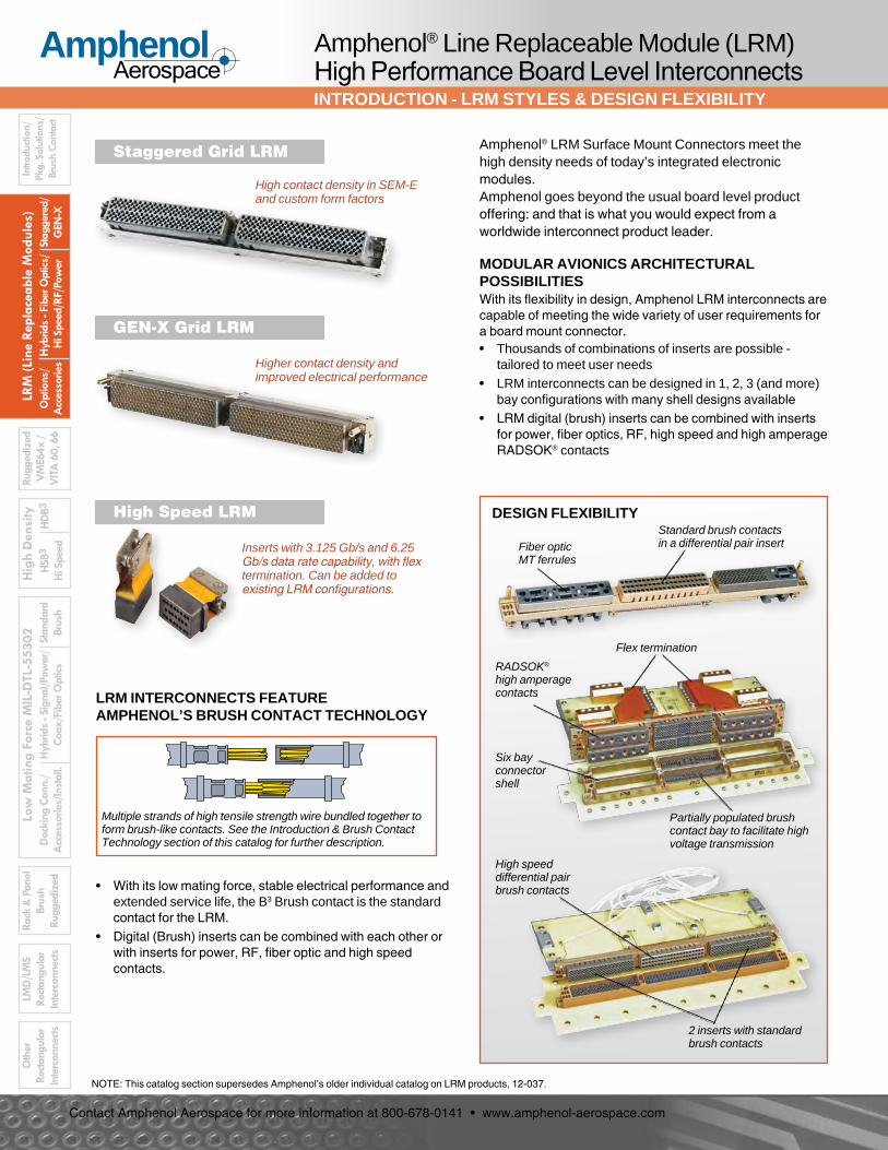
Amphenol® LRM Surface Mount Connectors meet the high density needs of today’s integrated electronic modules. Amphenol goes beyond the usual board level product offering: and that is what you would expect from a worldwide interconnect product leader.
Amphenol® Line Replaceable Module (LRM) High Performance Board Level InterconnectsINTRODUCTION - LRM STYLES & DESIGN FLEXIBILITY
High contact density in SEM-E and custom form factors
Higher contact density and improved electrical performance
MODULAR AVIONICS ARCHITECTURAL POSSIBILITIESWith its flexibility in design, Amphenol LRM interconnects are capable of meeting the wide variety of user requirements for a board mount connector.• Thousands of combinations of inserts are possible -
tailored to meet user needs• LRM interconnects can be designed in 1, 2, 3 (and more)
bay configurations with many shell designs available• LRM digital (brush) inserts can be combined with inserts
for power, fiber optics, RF, high speed and high amperage RADSOK® contacts
• With its low mating force, stable electrical performance and extended service life, the B3 Brush contact is the standard contact for the LRM.
• Digital (Brush) inserts can be combined with each other or with inserts for power, RF, fiber optic and high speed contacts.
Multiple strands of high tensile strength wire bundled together to form brush-like contacts. See the Introduction & Brush Contact Technology section of this catalog for further description.
DESIGN FLEXIBILITYStandard brush contacts in a differential pair insertFiber optic
MT ferrules
Flex termination
RADSOK® high amperage contacts
Partially populated brush contact bay to facilitate high voltage transmission
Six bay connector shell
2 inserts with standard brush contacts
High speed differential pair brush contacts
NOTE: This catalog section supersedes Amphenol’s older individual catalog on LRM products, 12-037.
High Speed LRM
Inserts with 3.125 Gb/s and 6.25 Gb/s data rate capability, with flex termination. Can be added to existing LRM configurations.
11
AmphenolAerospace
Contact Amphenol Aerospace for more information at 800-678-0141 • www.amphenol-aerospace.com
LRM (Line Replaceable M
odules)Staggered/
GEN
-X
Hybrids - Fiber O
ptics/ H
i Speed/RF/Power
Options/
Accessories
High D
ensityH
DB 3
HSB 3
Hi Speed
Low M
ating Force MIL-D
TL-55302Standard
BrushH
ybrids - Signal/Power/
Coax/Fiber Optics
Rack & Panel
Brush Ruggedized
Docking Conn./
Accessories/Install.
LMD
/LMS
Rectangular Interconnects
Other
Rectangular Interconnects
Introduction/Pkg. Solutions/Brush Contact
Ruggedized V
ME 64x/
VITA
60, 66Amphenol® Line Replaceable Module (LRM) InterconnectsLRM PRODUCT EVOLUTION
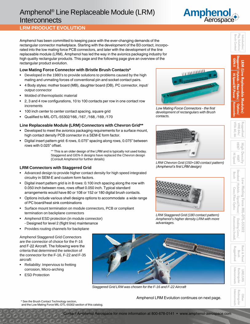
Amphenol has been committed to keeping pace with the ever-changing demands of the rectangular connector marketplace. Starting with the development of the B3 contact, incorpo-rated into the low mating force PCB connectors, and later with the development of the line replaceable module (LRM), Amphenol has led the way in the avionics packaging industry for high quality rectangular products. This page and the following page give an overview of the rectangular product evolution.
Low Mating Force Connector with Bristle Brush Contacts*• Developed in the 1980’s to provide solutions to problems caused by the high
mating and unmating forces of conventional pin and socket contact pairs.• 4 Body styles: mother board (MB), daughter board (DB), PC connector, input/
output connector• Molded of thermoplastic material• 2, 3 and 4 row configurations, 10 to 100 contacts per row in one contact row
increments• 100 inch center to center contact spacing, square grid• Qualified to MIL-DTL-55302/166, /167, /168, /169, /170
Line Replaceable Module (LRM) Connectors with Chevron Grid**• Developed to meet the avionics packaging requirements for a surface mount,
high contact density PCB connector in a SEM-E form factor.• Digital insert pattern grid: 6 rows, 0.075” spacing along rows, 0.075” between
rows with 0.025” offset.
Low Mating Force Connectors - the first development of rectangulars with Brush contacts.
LRM Chevron Grid (150+180 contact pattern) (Amphenol’s first LRM design)
LRM Staggered Grid (180 contact pattern) Amphenol’s higher density LRM with more advantages.
Amphenol Staggered Grid Connectors are the connector of choice for the F-16 and F-22 Aircraft. The following were the criteria that determined the selection of the connector for the F-16, F-22 and F-35 aircraft:• Reliability: Impervious to fretting
corrosion, Micro-arching• ESD Protection
Staggered Grid LRM was chosen for the F-16 and F-22 Aircraft
* See the Brush Contact Technology section, and the Low Mating Force MIL-DTL-55302 section of this catalog.
** This is an older design of the LRM and is typically not used today. Staggered and GEN-X designs have replaced the Chevron design (Consult Amphenol for further details)
LRM Connectors with Staggered Grid• Advanced design to provide higher contact density for high speed integrated
circuitry in SEM-E and custom form factors.• Digital insert pattern grid is in 8 rows: 0.100 inch spacing along the row with
0.050 inch between rows, rows offset 0.050 inch. Typical standard arrangements would have 80 or 108 or 152 or 180 digital brush contacts.
• Options include various shell designs options to accommodate a wide range of PC board/heat sink combinations
• Surface mount termination on module connectors, PCB or compliant termination on backplane connectors
• Amphenol ESD protection (in module connector) - Designed for level 2 (flight line) maintenance
• Provides routing channels for backplane
Amphenol LRM Evolution continues on next page.
12
AmphenolAerospace
Contact Amphenol Aerospace for more information at 800-678-0141 • www.amphenol-aerospace.com
LRM
(Lin
e Re
plac
eabl
e M
odul
es)
Stag
gere
d/
GEN
-X
Hyb
rids
- Fib
er O
ptics
/ H
i Spe
ed/R
F/Po
wer
O
ptio
ns/
Acc
esso
ries
Hig
h D
ensi
tyH
DB3
H
SB3
Hi S
peed
Low
Mat
ing
Forc
e M
IL-D
TL-5
5302 St
anda
rd
Brus
hH
ybrid
s - S
igna
l/Pow
er/
Coax
/Fib
er O
ptics
Rack
& P
anel
Br
ush
Rugg
ediz
edD
ocki
ng C
onn.
/ A
cces
sorie
s/In
stal
l.
Intro
ducti
on/
Pkg.
Sol
utio
ns/
Brus
h Co
ntac
t
LMD
/LM
S Re
ctang
ular
In
terc
onne
cts
Oth
er
Recta
ngul
ar
Inte
rcon
nects
Rugg
ediz
ed
VM
E64x
/
VITA
60,
66
Amphenol® Line Replaceable Module (LRM) Interconnects LRM PRODUCT EVOLUTION, CONTINUED
LRM Connectors with GEN-X Grid• Higher contact density and improved electrical performance• All the features of staggered LRM, including ESD protection (module connector)• Available in SEM-E and custom form factors• 236 contact pattern grid in 8 rows: 0.075 inch spacing along the row with 0.060
inch between rows, rows offset 0.0375 inch
LRM Staggered Grid Airflow-thru Connectors• LRM Staggered Airflow-thru inserts are available for wider board packages up to
0.425 in. These accommodate standard B3 tails in staggered pattern, but with increased spacing in the center, to accommodate airflow through heatsinks
LRM Connectors with Fiber Optics• Custom combinations of digital contacts and fiber optic termini were offered as
the product line further developed in the ‘90’s.• Configurations included:
• MIL-T-29504/4, /5, /14 & /15 termini • MT ferrule arrangements (2-24 fiber lines per ferrule)
LRM GEN-X Grid (236 contact pattern) Even higher densities with all the benefits of the Staggered Grid.
Certainly not standing still, and continuing to expand product offering, Amphenol now provides LRMs with higher contact densities, special purpose configurations and high speed inserts.
LRM with RF Contacts
LRM special 6 bay design with RADSOK® contacts, standard brush contacts, and flex circuitry termina-tion to module circuit card assemblies
LRM Staggered Grid Airflow-thru
LRM with Fiber Optic MT Ferrules
Board Level Interconnects of 2010 and Beyond -More and more the customer has demand-ed a high level of flexibility, with designs that incorporate higher speeds and special features going beyond the standard LRM. Configurations such as:• High speed GigaStak® LRM connectors
- capable of data rates up to 6.25 Gb/s, and DigiStak® LRM connectors capable of data rates up to 3.125 Gb/s
• High speed shielded contacts - coax, triax, twinax, differential twinax, and quadrax contacts available in inserts of the LRM
• Combinations of power contacts, standard brush, high power, differential pair brush, and fiber optic termini
• Incorporation of Flex Circuits for more versatility of PC board terminations• Custom shells with multiple bay configurations, special keying
components or special guide/ground pins• Compliant pin contacts for press-fit termination to circuit boards.
Amphenol Backplane CapabilitiesAmphenol backplanes incorporate a wide range of our interconnects. See Other Rectangular Interconnects Section of this catalog, page 117, for more information on Amphenol backplanes.
LRM Connectors to Accommodate RF Contacts• LRM inserts are available with RF contacts:
• LRM Power Supply Modules• Custom designs of LRMs have been developed with
270VDC sections which are capable of providing corona-free operation at 100,000 feet. They utilize size 22D contacts and are available in both crimp and compliant pin terminations.
LRM with High Amperage RADSOK® Contacts• The RADSOK® contact technology enables high current flow with
minimal voltage loss and low insertion force
LRM backplane (left) and module connector (right) incorporating high amperage RADSOK® contacts (crimp style shown).
High Speed GigaStak® , capable of data rates of 6.250 Gbps
* See Other Rectangular Interconnects Section, page 126 for more information on SMPM contacts.
13
AmphenolAerospace
Contact Amphenol Aerospace for more information at 800-678-0141 • www.amphenol-aerospace.com
LRM (Line Replaceable M
odules)Staggered/
GEN
-X
Hybrids - Fiber O
ptics/ H
i Speed/RF/Power
Options/
Accessories
High D
ensityH
DB 3
HSB 3
Hi Speed
Low M
ating Force MIL-D
TL-55302Standard
BrushH
ybrids - Signal/Power/
Coax/Fiber Optics
Rack & Panel
Brush Ruggedized
Docking Conn./
Accessories/Install.
LMD
/LMS
Rectangular Interconnects
Other
Rectangular Interconnects
Introduction/Pkg. Solutions/Brush Contact
Ruggedized V
ME 64x/
VITA
60, 66Amphenol Leads in Board Level Product TechnologyLRM DESIGN ENGINEERING
We take pride that Amphenol Aerospace is the undisputed leader in interconnect systems for aerospace/harsh environment applications. Such applications require a high degree of engineering sophistication and precision manu-facturing capability that only a company that has been in the interconnection product design and manufacturing business for over 50 years can offer.We have earned the reputation as the leader in the military electrical connection arena especially for military cylindrical connectors, and are fast becoming the leader for rectangu-lar and surface mount interconnects.
Expert design and applications engineering provides solid modeling and full Pro-Engineer® capabilities to develop new interconnection designs and perform structural analysis. Marketing product managers team with skilled engineers and production specialists in a customer-driven approach to produce the end result: defect-free parts, cost effectiveness, shorter lead and delivery times, and satisfied customers.The photo top right shows the CST Microwave Studio® signal integrity modeling and simulation software at Amphenol. This state-of-the-art technology allows charac-terization of current connector designs and rapidly aids in the development of new high speed signal designs. It consists of a 3D, full-wave electromagnetic field solver for simulating electrical performance, producing SPICE models and eye diagrams.Amphenol’s capability for testing of it’s wide range of cylindrical and rectangular connector products also includes vibration and shock testing, humidity, engagement/separation force evaluation, durability testing, as well as salt spray/fog, corona, ESD, optical performance testing and altitude simulation.
Above and below are production areas for LRM interconnects and heatsinks. Note the orange balls on the machines - these are used as a quick checking device for processes.
* VME64x products are covered on page 43.
Close-up photo showing vertical machining of heatsink housings done at Amphenol.
Our LRM and VME64x* products are used on major programs that include the following and more:
Engineers working at the signal integrity modeling and simulation software suite at Amphenol Aerospace Operations. (See page 28 for more information on Amphenol’s testing of Hi-Speed LRM connectors).
14
AmphenolAerospace
Contact Amphenol Aerospace for more information at 800-678-0141 • www.amphenol-aerospace.com
LRM
(Lin
e Re
plac
eabl
e M
odul
es)
Stag
gere
d/
GEN
-X
Hyb
rids
- Fib
er O
ptics
/ H
i Spe
ed/R
F/Po
wer
O
ptio
ns/
Acc
esso
ries
Hig
h D
ensi
tyH
DB3
H
SB3
Hi S
peed
Low
Mat
ing
Forc
e M
IL-D
TL-5
5302 St
anda
rd
Brus
hH
ybrid
s - S
igna
l/Pow
er/
Coax
/Fib
er O
ptics
Rack
& P
anel
Br
ush
Rugg
ediz
edD
ocki
ng C
onn.
/ A
cces
sorie
s/In
stal
l.
Intro
ducti
on/
Pkg.
Sol
utio
ns/
Brus
h Co
ntac
t
LMD
/LM
S Re
ctang
ular
In
terc
onne
cts
Oth
er
Recta
ngul
ar
Inte
rcon
nects
Rugg
ediz
ed
VM
E64x
/
VITA
60,
66
Amphenol Leads in Board Level TechnologyLRM MANUFACTURING EXPERTISE
Amphenol Aerospace is highly integrated to design, manufacture, assemble and ship an extensive variety of line replaceable module and backplane connectors. We also supply a wide range of heatsink hardware associated with this type of connector. The photo on right shows several heatsink forms used in the manufacture of LRM interconnects. For more information on heatsinks, see the Other Board Level and Rectangular Interconnects Section, pages 112 & 113.Manufacturing equipment photos shown below demonstrate Amphenol’s high technology capabil-ity. Focus is always on cost effective production and continuous improvement of processes. Manufactur-ing capabilities include state-of-the-art robotically controlled milling machines and CNC machining, as well as impact and extruding, plating, screw machining, and process control.
Amphenol divisions work together to provide a very broad manufactur-ing capability for board level interconnects:• Amphenol Aerospace (AAO)* has leading expertise in the
production of line replaceable module inter-connects, VME64x interconnects and low mating force brush connectors.
• Amphenol Backplane Systems (ABS)** has leading expertise in the manufacture of custom backplane assemblies - high density, ruggedized, board to backplane interconnects.
• Amphenol Printed Circuits (APC)*** has leading expertise in the manufacture of flex circuitry products used in connector-to-board attachment.
These companies of Amphenol Corporation combine to provide design, applications engineering, fabrication, value-added assembly and testing to meet customer requirements as well as to develop products for emerging technologies.
Variety of heatsinks and connector shells manufactured by Amphenol.
* This catalog covers the rectangular interconnect products offered by AAO division. Go online at www.amphenol-aerospace to see the wide range of cylindrical and other interconnect products offered by AAO. And see the Other Rectangular Products section at the end of this catalog for other Amphenol divisions offerings of rectangular interconnects.
** For more information on backplane assemblies: page 117 and online at www.amphenol-abs.com.
*** For more information on flex circuit products: page 121 and online at www.amphenolapc.com.
CMM measuring is done to check machined parts.
THE ADVANTAGE OF AMPHENOL’S WIDE DIVISIONAL CAPABILITY
Amphenol’s high technology computer driven equipment for manufacturing heatsinks.
Checking for dimensional accuracy of LRM parts and heatsinks.
15
AmphenolAerospace
Contact Amphenol Aerospace for more information at 800-678-0141 • www.amphenol-aerospace.com
LRM (Line Replaceable M
odules)Staggered/
GEN
-X
Hybrids - Fiber O
ptics/ H
i Speed/RF/Power
Options/
Accessories
High D
ensityH
DB 3
HSB 3
Hi Speed
Low M
ating Force MIL-D
TL-55302Standard
BrushH
ybrids - Signal/Power/
Coax/Fiber Optics
Rack & Panel
Brush Ruggedized
Docking Conn./
Accessories/Install.
LMD
/LMS
Rectangular Interconnects
Other
Rectangular Interconnects
Introduction/Pkg. Solutions/Brush Contact
Ruggedized V
ME 64x/
VITA
60, 66LRM Module Connector General InformationSTAGGERED GRID DOUBLE BAY SHOWN
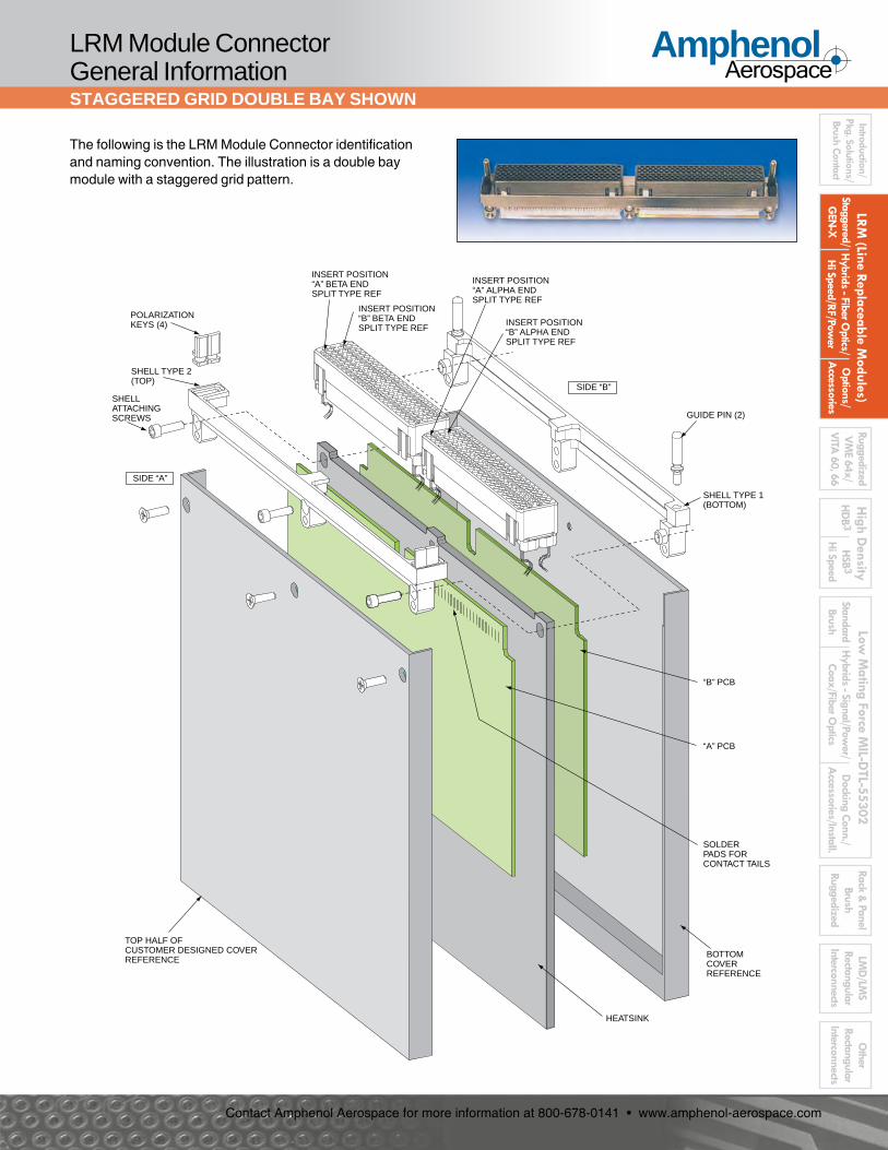
The following is the LRM Module Connector identification and naming convention. The illustration is a double bay module with a staggered grid pattern.
POLARIZATIONKEYS (4)
SHELL TYPE 2(TOP)
INSERT POSITION“A” BETA ENDSPLIT TYPE REF
INSERT POSITION“B” BETA ENDSPLIT TYPE REF
INSERT POSITION“A” ALPHA ENDSPLIT TYPE REF
INSERT POSITION“B” ALPHA ENDSPLIT TYPE REF
GUIDE PIN (2)
SHELL TYPE 1(BOTTOM)
“B” PCB
“A” PCB
HEATSINK
SHELLATTACHINGSCREWS
TOP HALF OFCUSTOMER DESIGNED COVERREFERENCE
BOTTOMCOVERREFERENCE
SOLDERPADS FORCONTACT TAILS
SIDE “A”
SIDE “B”
16
AmphenolAerospace
Contact Amphenol Aerospace for more information at 800-678-0141 • www.amphenol-aerospace.com
LRM
(Lin
e Re
plac
eabl
e M
odul
es)
Stag
gere
d/
GEN
-X
Hyb
rids
- Fib
er O
ptics
/ H
i Spe
ed/R
F/Po
wer
O
ptio
ns/
Acc
esso
ries
Hig
h D
ensi
tyH
DB3
H
SB3
Hi S
peed
Low
Mat
ing
Forc
e M
IL-D
TL-5
5302 St
anda
rd
Brus
hH
ybrid
s - S
igna
l/Pow
er/
Coax
/Fib
er O
ptics
Rack
& P
anel
Br
ush
Rugg
ediz
edD
ocki
ng C
onn.
/ A
cces
sorie
s/In
stal
l.
Intro
ducti
on/
Pkg.
Sol
utio
ns/
Brus
h Co
ntac
t
LMD
/LM
S Re
ctang
ular
In
terc
onne
cts
Oth
er
Recta
ngul
ar
Inte
rcon
nects
Rugg
ediz
ed
VM
E64x
/
VITA
60,
66
LRM Backplane Connector General InformationSTAGGERED GRID DOUBLE BAY SHOWN
The following diagram shows an exploded view of an LRM staggered grid backplane connector in a two bay configuration.
BACKPLANE CONNECTOR SHELL(TYPICAL CONTAINMENT OF 2 BAY INSERTASSEMBLY SHOWN)
BRUSH PINS
17
AmphenolAerospace
Contact Amphenol Aerospace for more information at 800-678-0141 • www.amphenol-aerospace.com
LRM (Line Replaceable M
odules)Staggered/
GEN
-X
Hybrids - Fiber O
ptics/ H
i Speed/RF/Power
Options/
Accessories
High D
ensityH
DB 3
HSB 3
Hi Speed
Low M
ating Force MIL-D
TL-55302Standard
BrushH
ybrids - Signal/Power/
Coax/Fiber Optics
Rack & Panel
Brush Ruggedized
Docking Conn./
Accessories/Install.
LMD
/LMS
Rectangular Interconnects
Other
Rectangular Interconnects
Introduction/Pkg. Solutions/Brush Contact
Ruggedized V
ME 64x/
VITA
60, 66
CONTACT PATTERNS
Staggered Grid LRM & Staggered Grid Airflow-thru
STAGGERED GRID DESCRIPTIONThe LRM standard staggered grid pattern employs surface mount leads on .025 inch centerlines (pitch). Insert patterns of digital brush contacts are in 80, 108, 152 and 180 contact counts. See typical arrangement drawings on pages 19 and 20.
STAGGERED AIRFLOW-THRU GRID DESCRIPTIONThe staggered grid airflow-thru inserts were designed to accommodate wider board packaging and airflow-thru heatsinks. Insert patterns of digital brush contacts are same as the staggered grid pattern (80, 108, 152 and 180 contact counts). See typical arrangement drawings on page 21.
.150 TYP( 3X .050 )
.150 TYP( 3X .050 )
.050TYP
.050 TYP
.050 TYP
.100 TYP
ConnectorCenterline
.075TYP
All dimensions in inches.
STAGGERED
.150 TYP( 3X .050 )
.150 TYP( 3X .050 )
.050TYP
.050 TYP
.050 TYP
.100 TYP
ConnectorCenterline
.250TYP
All dimensions in inches.
STAGGERED AIRFLOW-THRU
Staggered grid airflow-thru backplane insert.
Two bay, 360 contact, module connector with standard staggered grid pattern
18
AmphenolAerospace
Contact Amphenol Aerospace for more information at 800-678-0141 • www.amphenol-aerospace.com
Contact Amphenol Aerospace for more information at 800-678-0141 • www.amphenol-aerospace.com
LRM (Line Replaceable M
odules)Staggered/
GEN
-X
Hybrids - Fiber O
ptics/ H
i Speed/RF/Power
Options/
Accessories
High D
ensityH
DB 3
HSB 3
Hi Speed
Low M
ating Force MIL-D
TL-55302Standard
BrushH
ybrids - Signal/Power/
Coax/Fiber Optics
Rack & Panel
Brush Ruggedized
Docking Conn./
Accessories/Install.
LMD
/LMS
Rectangular Interconnects
Other
Rectangular Interconnects
Introduction/Pkg. Solutions/Brush Contact
Ruggedized V
ME 64x/
VITA
60, 66
TYPICAL ARRANGEMENTS
Staggered Grid LRM
Staggered Grid LRM interconnects can be one, two or three bay configurations, and special additional bay arrangements. The typical arrange-ments shown here are depicted in one bay drawings. Amphenol’s design flexibility also allow for combinations of contact types. These arrange-ments represent the versatility that can be arrived at by arranging digital (brush) inserts with inserts for power, RF, fiber optic and high speed contacts in various combinations within a typical bay. Consult Amphenol Aerospace for assistance in designing the LRM that best meets your specific application needs. See page 41 for an aid in selection and ordering.
80 brush contacts
108 brush contacts
152 brush contacts
180 brush contacts
108 brush contacts plus 6 sz. 12 power or coax contacts
108 brush contacts plus 8 coax contacts
80 brush contacts plus 10 coax contacts
80 brush contacts plus 12 sz. 12 power or coax contacts
152 brush contacts plus 2 sz. 12 power or coax contacts
152 brush contacts plus 4 sz. 16 power or coax contacts
108 brush contacts plus 270 VDC power input
80 brush contacts plus 270 VDC power input
22 sz. 12 power contacts
152 brush contacts plus 2 sz. 12 power or coax contacts
Example of a backplane connector in a 2 bay arrangement with inserts of staggered brush contacts and coax (size 12) contacts.
20
AmphenolAerospace
Contact Amphenol Aerospace for more information at 800-678-0141 • www.amphenol-aerospace.com
LRM
(Lin
e Re
plac
eabl
e M
odul
es)
Stag
gere
d/
GEN
-X
Hyb
rids
- Fib
er O
ptics
/ H
i Spe
ed/R
F/Po
wer
O
ptio
ns/
Acc
esso
ries
Hig
h D
ensi
tyH
DB3
H
SB3
Hi S
peed
Low
Mat
ing
Forc
e M
IL-D
TL-5
5302 St
anda
rd
Brus
hH
ybrid
s - S
igna
l/Pow
er/
Coax
/Fib
er O
ptics
Rack
& P
anel
Br
ush
Rugg
ediz
edD
ocki
ng C
onn.
/ A
cces
sorie
s/In
stal
l.
Intro
ducti
on/
Pkg.
Sol
utio
ns/
Brus
h Co
ntac
t
LMD
/LM
S Re
ctang
ular
In
terc
onne
cts
Oth
er
Recta
ngul
ar
Inte
rcon
nects
Rugg
ediz
ed
VM
E64x
/
VITA
60,
66
Staggered Grid LRM
TYPICAL ARRANGEMENTS
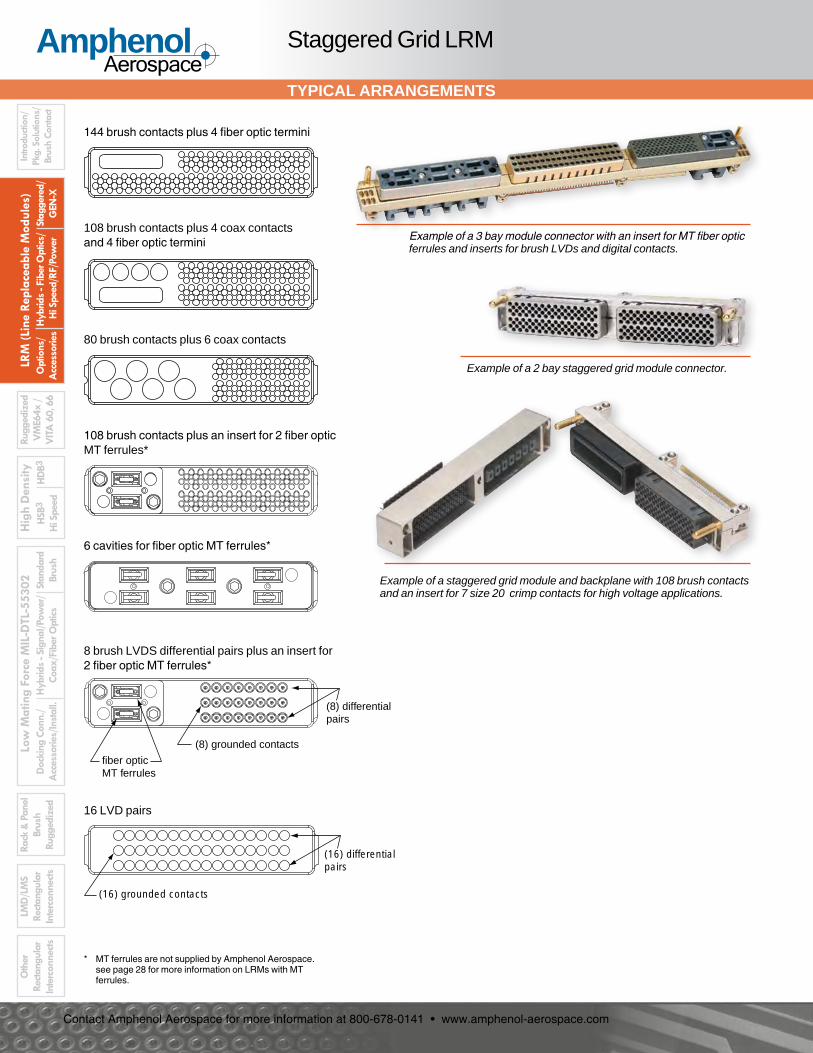
Example of a 2 bay staggered grid module connector.
8 brush LVDS differential pairs plus an insert for 2 fiber optic MT ferrules*
Example of a 3 bay module connector with an insert for MT fiber optic ferrules and inserts for brush LVDs and digital contacts.
108 brush contacts plus an insert for 2 fiber optic MT ferrules*
6 cavities for fiber optic MT ferrules*
16 LVD pairs
(8) differentialpairs
(8) grounded contacts
fiber opticMT ferrules
(16) differentialpairs
(16) grounded contacts
144 brush contacts plus 4 fiber optic termini
108 brush contacts plus 4 coax contacts and 4 fiber optic termini
80 brush contacts plus 6 coax contacts
Example of a staggered grid module and backplane with 108 brush contacts and an insert for 7 size 20 crimp contacts for high voltage applications.
* MT ferrules are not supplied by Amphenol Aerospace. see page 28 for more information on LRMs with MT ferrules.
21
AmphenolAerospace
Contact Amphenol Aerospace for more information at 800-678-0141 • www.amphenol-aerospace.com
LRM (Line Replaceable M
odules)Staggered/
GEN
-X
Hybrids - Fiber O
ptics/ H
i Speed/RF/Power
Options/
Accessories
High D
ensityH
DB 3
HSB 3
Hi Speed
Low M
ating Force MIL-D
TL-55302Standard
BrushH
ybrids - Signal/Power/
Coax/Fiber Optics
Rack & Panel
Brush Ruggedized
Docking Conn./
Accessories/Install.
LMD
/LMS
Rectangular Interconnects
Other
Rectangular Interconnects
Introduction/Pkg. Solutions/Brush Contact
Ruggedized V
ME 64x/
VITA
60, 66
Center inserts contain 108 brush contacts, staggered grid
Module connector
Backplane connector
Staggered Grid Airflow-thru LRM
ARRANGEMENTS, CUSTOM SHELLS
152 brush contacts (airflow-thru)
80 brush contacts (airflow-thru)
180 brush contacts (airflow-thru)
Module and backplane connectors with staggered airflow-thru inserts. Shown are 216 brush contacts and inserts for size 12 RADSOK® crimp contacts.
108 brush contacts (airflow-thru)
The typical Airflow-thru arrangements are with brush contacts. The arrangements shown at left for staggered grid Airflow-thru are typical of what has been developed for customer requirements.
Staggered Grid Airflow-thru pattern - in a module on right, and in a backplane on left. Note the increased spacing in the center. This is designed for wider board packages, and accommodates airflow-thru heatsinks. (See illustration on page 18).
Amphenol designs and builds custom shell configurations such as the module face plate and its mating backplane connector.
Underside of Backplane, showing size 8 & 12 RADSOK® contacts with compliant termination.
This custom Airflow-thru module contains RADSOK® high amperage socket contacts in sizes 8 and 12.
See more description of RADSOK® contacts, page 124.
Closeup of insert with compliant pin termination power contacts.
LRMs with airflow-thru inserts can be custom designed in combination with power contacts, such as the example below.
22
AmphenolAerospace
Contact Amphenol Aerospace for more information at 800-678-0141 • www.amphenol-aerospace.com
LRM
(Lin
e Re
plac
eabl
e M
odul
es)
Stag
gere
d/
GEN
-X
Hyb
rids
- Fib
er O
ptics
/ H
i Spe
ed/R
F/Po
wer
O
ptio
ns/
Acc
esso
ries
Hig
h D
ensi
tyH
DB3
H
SB3
Hi S
peed
Low
Mat
ing
Forc
e M
IL-D
TL-5
5302 St
anda
rd
Brus
hH
ybrid
s - S
igna
l/Pow
er/
Coax
/Fib
er O
ptics
Rack
& P
anel
Br
ush
Rugg
ediz
edD
ocki
ng C
onn.
/ A
cces
sorie
s/In
stal
l.
Intro
ducti
on/
Pkg.
Sol
utio
ns/
Brus
h Co
ntac
t
LMD
/LM
S Re
ctang
ular
In
terc
onne
cts
Oth
er
Recta
ngul
ar
Inte
rcon
nects
Rugg
ediz
ed
VM
E64x
/
VITA
60,
66
TERMINATION OPTIONS
Staggered Grid LRM
BOARD PACKAGETHICKNESS
HEATSINKTHICKNESS
The following is a guide to the part number suffixes to be used when ordering LRM Connectors. Due to the complexity and number of variations within the part numbering, it is necessary to consult Amphenol Aerospace for assistance when building these part numbers. See page 41 for an aid in selection and ordering, and call Amphenol at 607-563-5011 for technical support.
10-507 .....Designates Amphenol LRM Connectors
XXX-X ......Module Insert Arrangement Number - To be assigned by Amphenol.
( ) ............Heatsink Thickness Suffix for Modules
10-507XXX-X( )( )An example of a typical Amphenol Module part number is: 10-507XXX-X( )( )
An example of a typical Amphenol Backplane part number is:
10-507 .....Designates Amphenol LRM Connectors
XXX-X ......Backplane Insert Arrangement Number - To be assigned by Amphenol.
( ) ............Termination Style Suffix for Backplanes
( ) ............Board Package Thickness Suffix for Modules
* .175 is added for increased center spacing in the airflow-thru staggered style
( ) ............Termination Stickout Suffix for Backplanes
Contact Amphenol Aerospace for more information at 800-678-0141 • www.amphenol-aerospace.com
LRM (Line Replaceable M
odules)Staggered/
GEN
-X
Hybrids - Fiber O
ptics/ H
i Speed/RF/Power
Options/
Accessories
High D
ensityH
DB 3
HSB 3
Hi Speed
Low M
ating Force MIL-D
TL-55302Standard
BrushH
ybrids - Signal/Power/
Coax/Fiber Optics
Rack & Panel
Brush Ruggedized
Docking Conn./
Accessories/Install.
LMD
/LMS
Rectangular Interconnects
Other
Rectangular Interconnects
Introduction/Pkg. Solutions/Brush Contact
Ruggedized V
ME 64x/
VITA
60, 66Staggered Grid LRM
TYPICAL PERFORMANCE, MATERIALS LIST
Table 1 below identifies the typical electrical, mechanical and environmental performance of an Amphenol 2 bay LRM connector assembly with 360 brush contacts in staggered grid. This data was program specific and does not reflect actual performance limitations. Table II below provides a materials list for the components of staggered grid LRM connectors.
TABLE I: PERFORMANCE
ELECTRICAL PERFORMANCE
Electrical Parameters PerformanceCurrent carrying capability 10°C temperature rise at 2A and 30°C rise at 3AContact resistance 30 milliohms max. per contact, 25 milliohms max. averageDielectric withstanding voltage at sea level 100 VRMS, 60 HzDielectric withstanding voltage at altitude 100 VRMS, 60 Hz at 70,000 ft.Insulation Resistance 1000 megohm minimum at 100V d.c.Electrostatic Discharge Protection (module only) ± 25,000 minimum air and direct discharge (see pg. XX for details)
MECHANICAL PERFORMANCE
Mechanical Parameters PerformanceContact retention (solder type backplane assembly) Maximum displacement of 0.010” at 1 pound loadMating and unmating forces Maximum 40.0 pounds mating and unmatingVibration (Sinusoidal, 20g peak max.) No electrical discontinuity >1 µSVibration (Random, 11.6g RMS max.) No electrical discontinuity >1 µSShock (50g max. shock pulse) No electrical discontinuity >1 µSSolderability Minimum 95% solder coverageResistance to soldering heat 260°C dip for 10 seconds
ENVIRONMENTAL PERFORMANCE
Environmental Parameters PerformanceTemperature life 250 hours at 125°C maximumConnector durability 500 cycles mating and unmatingSalt fog exposure 48 hours maximum direct exposure (5% NaCl)Thermal shock 500 cycles at +125°C / –65°CHumidity exposure 240 hours at 90 - 98%Contamination exposure Sand and dust per MIL-STD-202 Method 110Resistance to solvents Boiling Trichloroethylene fumes and solution
TABLE II: MATERIALS LIST
ENVIRONMENTAL PERFORMANCE
Part Material / Finish DescriptionBrush wires Beryllium copper per ASTM B197; finish is gold per ASTM B488 over nickel per AMS-QQ-N-290. (The exposed ends of the
brush wires need not be plated).
Module contacts Beryllium copper per ASTM B534 C17500, or C17510 except temper HTC; finish on contact body is matte tin-lead per ASTM B579; finish on termination end is 60/40 or 63/37 tin-lead dip per J-STD-004, -005 and -006.
Backplane contacts (Compliant termination)
Contact barrel: brass per ASTM B4531/B453M-01 similar to UNS C33500; finish is tin-lead per SAE-AMS-P-81728 (min. 15% ±5% lead) over nickel. Contact tail: beryllium copper per ASTM B-534 alloy 17510 HT; finish is gold per ASTM B-488 over nickel per AMS-QQ-N-290. Contact sleeve: stainless steel per AMS 5514; finish is black oxide per MIL-DTL-13924 and conformally coated per MIL-I-46058.
Backplane contacts (PCB termination)
Contact body: brass similar to UNS C33500; finish is gold over nickel; termination end is 60/40 or 63/37 tin lead dip. Contact sleeve: stainless steel per AMS 5514; finish is black oxide per MIL-DTL-13924 and conformally coated per MIL-I-46058.
Insulators Polyphenylene Sulfide or Liquid Crystal Polymer per MIL-M-24519
Organizer Polyphenylene Sulfide or Liquid Crystal Polymer per MIL-M-24519
Shells Aluminum alloy 6061-T6 per AMS 4150; finish is electroless nickel per SAE AMS 2404.
ESD shields Aluminum alloy 6061-T6 per AMS 4150; finish is hardcoat anodize per MIL-A-8625 with epoxy final coat. Ground tabs are chromate treated (irridite).
Polarization keys Stainless steel per AMS 5640; finish is black oxide per MIL-DTL-13924. Key retaining ring is Polyamide (nylon 12) with 50% glass filled fibers.
Guide pins Beryllium copper alloy per ASTM B196, finish is gold per ASTM B 488 over nickel per AMS-QQ-N-290.
24
AmphenolAerospace
Contact Amphenol Aerospace for more information at 800-678-0141 • www.amphenol-aerospace.com
LRM
(Lin
e Re
plac
eabl
e M
odul
es)
Stag
gere
d/
GEN
-X
Hyb
rids
- Fib
er O
ptics
/ H
i Spe
ed/R
F/Po
wer
O
ptio
ns/
Acc
esso
ries
Hig
h D
ensi
tyH
DB3
H
SB3
Hi S
peed
Low
Mat
ing
Forc
e M
IL-D
TL-5
5302 St
anda
rd
Brus
hH
ybrid
s - S
igna
l/Pow
er/
Coax
/Fib
er O
ptics
Rack
& P
anel
Br
ush
Rugg
ediz
edD
ocki
ng C
onn.
/ A
cces
sorie
s/In
stal
l.
Intro
ducti
on/
Pkg.
Sol
utio
ns/
Brus
h Co
ntac
t
LMD
/LM
S Re
ctang
ular
In
terc
onne
cts
Oth
er
Recta
ngul
ar
Inte
rcon
nects
Rugg
ediz
ed
VM
E64x
/
VITA
60,
66
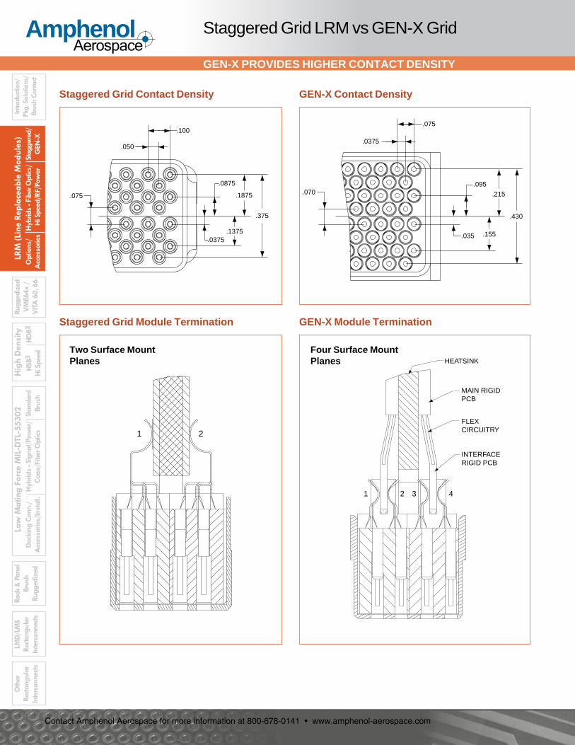
Staggered Grid LRM vs GEN-X Grid
GEN-X PROVIDES HIGHER CONTACT DENSITY
1 2 3 4
INTERFACERIGID PCB
FLEXCIRCUITRY
MAIN RIGIDPCB
HEATSINK
1 2
Staggered Grid Module Termination
Staggered Grid Contact Density
Two Surface Mount Planes
Four Surface Mount Planes
GEN-X Contact Density
.375
.1875
.1375.0375
.0875
.050
.100
.075
.0375
.075
.430
.215
.155.035
.095.070
GEN-X Module Termination
25
AmphenolAerospace
Contact Amphenol Aerospace for more information at 800-678-0141 • www.amphenol-aerospace.com
LRM (Line Replaceable M
odules)Staggered/
GEN
-X
Hybrids - Fiber O
ptics/ H
i Speed/RF/Power
Options/
Accessories
High D
ensityH
DB 3
HSB 3
Hi Speed
Low M
ating Force MIL-D
TL-55302Standard
BrushH
ybrids - Signal/Power/
Coax/Fiber Optics
Rack & Panel
Brush Ruggedized
Docking Conn./
Accessories/Install.
LMD
/LMS
Rectangular Interconnects
Other
Rectangular Interconnects
Introduction/Pkg. Solutions/Brush Contact
Ruggedized V
ME 64x/
VITA
60, 66Staggered Grid LRM vs GEN-X Grid
GEN-X PROVIDES HIGHER CONTACT DENSITY
Staggered Grid LRM has 0.025 tail to tail centerline spacing
Staggered Grid Tail to Tail Placement
GEN-X Tail to Tail Placement
GEN-X is Designed to Terminate to Rigid-Flex PCB Attachment
MAIN RIGID PCB
FLEXCIRCUITRY
MODULEINSERT ASSEMBLY
INTERFACE RIGID PCB
HEATSINK
GEN-X Grid LRM has 0.0375 tail to tail centerline spacing
26
AmphenolAerospace
Contact Amphenol Aerospace for more information at 800-678-0141 • www.amphenol-aerospace.com
LRM
(Lin
e Re
plac
eabl
e M
odul
es)
Stag
gere
d/
GEN
-X
Hyb
rids
- Fib
er O
ptics
/ H
i Spe
ed/R
F/Po
wer
O
ptio
ns/
Acc
esso
ries
Hig
h D
ensi
tyH
DB3
H
SB3
Hi S
peed
Low
Mat
ing
Forc
e M
IL-D
TL-5
5302 St
anda
rd
Brus
hH
ybrid
s - S
igna
l/Pow
er/
Coax
/Fib
er O
ptics
Rack
& P
anel
Br
ush
Rugg
ediz
edD
ocki
ng C
onn.
/ A
cces
sorie
s/In
stal
l.
Intro
ducti
on/
Pkg.
Sol
utio
ns/
Brus
h Co
ntac
t
LMD
/LM
S Re
ctang
ular
In
terc
onne
cts
Oth
er
Recta
ngul
ar
Inte
rcon
nects
Rugg
ediz
ed
VM
E64x
/
VITA
60,
66
.060Spacing
.070
.035
.0375 Offset.075
.430
All dimensions in inches.
GEN-X
The LRM GEN-X pattern employs surface mount leads on a .0375 inch center line (module connector), yet provides higher contact density than the Staggered grid pattern. GEN-X provides all the same features as the staggered grid LRM:• GEN-X digital (brush) inserts are
available in 118 and 236 pin contact counts.
• Digital contacts can also be combined with inserts for fiber optics, RF, poser and high speed contacts.
• Various combinations of inserts can be provided in 1, 2 or 3 bay shell configurations.
• Typical insert arrangements shown here are depicted in one bay drawing.
Consult Amphenol Aerospace for assistance in designing the LRM that best meets your specific application needs. See page 41 for an aid in selection and ordering of LRM and LRU interconnects.
118 brush contacts
236 brush contacts
140 brush contacts plus an insert for 2 fiber optic MT ferrules*
212 brush contacts plus 2 sz. 16 power or coax contacts
170 brush contacts plus 6 sz. 16 power or coax contacts
170 brush contacts plus 4 fiber optic termini and 2 sz. 16 contacts
Example of a 2 bay GEN-X module connector.
Example of a 3 bay GEN-X backplane connector.
CONTACT PATTERN & ARRANGEMENTS
GEN-X Grid LRM
* MT ferrules are not supplied by Amphenol Aerospace. see page 28 for more information on LRMs with MT ferrules.
27
AmphenolAerospace
Contact Amphenol Aerospace for more information at 800-678-0141 • www.amphenol-aerospace.com
LRM (Line Replaceable M
odules)Staggered/
GEN
-X
Hybrids - Fiber O
ptics/ H
i Speed/RF/Power
Options/
Accessories
High D
ensityH
DB 3
HSB 3
Hi Speed
Low M
ating Force MIL-D
TL-55302Standard
BrushH
ybrids - Signal/Power/
Coax/Fiber Optics
Rack & Panel
Brush Ruggedized
Docking Conn./
Accessories/Install.
LMD
/LMS
Rectangular Interconnects
Other
Rectangular Interconnects
Introduction/Pkg. Solutions/Brush Contact
Ruggedized V
ME 64x/
VITA
60, 66
LRMS WITH FIBER OPTIC TERMINI
LRM Interconnect Options
High speed fiber optic transmission is available within LRM connectors for use in advanced avionics systems. Optical performance of fiber optic termini within in LRM connectors are the same as termini used in circular connectors.* Insertion losses range from .3dB to <1.5dB depending upon launch conditions, fiber NA, fiber size and the type of termination.Inserts for MIL-T-29504/1, /2, /14 and /15 can be incorporated. Termini for LRMs can be supplied - consult Amphenol Aerospace for ordering information. The termini are deter-mined by insert and shell style of the connector.LRM interconnects can have hybrid arrangements of fiber optics with Brush contacts, as well as other contact types.
GEN-X Patterns with MIL-T-29504 Fiber Optic Termini(This drawing is also shown with other GEN-X patterns on page 26).
144 brush contacts plus an insert for 4 fiber optic termini
108 brush contacts plus an insert for 4 shielded contacts and an insert for 4 fiber optic termini
170 brush contacts plus an insert for 4 fiber optic termini plus 2 sz. 16 contacts
Staggered Grid Patterns with MIL-T-29504 Fiber Optic Termini(These drawings are also shown with other staggered grid patterns on pages 19 and 20).
*For more information on Amphenol fiber optic circular connectors, see Amphenol Circular Interconnects Catalog 12-C3, Fiber Optic section
Examples of LRM connectors with fiber optic multi-mode termini in combination with brush contacts.
28
AmphenolAerospace
Contact Amphenol Aerospace for more information at 800-678-0141 • www.amphenol-aerospace.com
LRM
(Lin
e Re
plac
eabl
e M
odul
es)
Stag
gere
d/
GEN
-X
Hyb
rids
- Fib
er O
ptics
/ H
i Spe
ed/R
F/Po
wer
O
ptio
ns/
Acc
esso
ries
Hig
h D
ensi
tyH
DB3
H
SB3
Hi S
peed
Low
Mat
ing
Forc
e M
IL-D
TL-5
5302 St
anda
rd
Brus
hH
ybrid
s - S
igna
l/Pow
er/
Coax
/Fib
er O
ptics
Rack
& P
anel
Br
ush
Rugg
ediz
edD
ocki
ng C
onn.
/ A
cces
sorie
s/In
stal
l.
Intro
ducti
on/
Pkg.
Sol
utio
ns/
Brus
h Co
ntac
t
LMD
/LM
S Re
ctang
ular
In
terc
onne
cts
Oth
er
Recta
ngul
ar
Inte
rcon
nects
Rugg
ediz
ed
VM
E64x
/
VITA
60,
66
LRMS WITH INSERTS FOR MT FERRULE FIBER OPTICS
LRM Interconnect Options
Insert for 108 brush contacts plus an insert for 2 fiber optic MT ferrules
Insert with cavities for 6 fiber optic MT ferrules
Insert with 8 brush differential pairs plus an insert for 2 fiber optic MT ferrules
Staggered Grid Patterns with MT Ferrule Fiber Optics(These drawings are also shown with other staggered grid patterns on pages 19 and 20).
Through Amphenol’s LRM design flexibility, inserts are available to house high speed MT ferrules which can have 12 or 24 fiber lines per ferrule. MT ferrules are not supplied by Amphenol; they must be purchased separately.
Example of an LRM module connector with MT fiber optic inserts in combination with inserts for brush LVDs and digital contacts.
STRAINRELIEF
SPRING
MT FERRULEWITH RIBBON
REAR INSERT
FRONTINSERT
PIN CLAMP
FRONTINSERT
REARINSERT
MT FERRULEWITH RIBBON
GEN-X Patterns with MT Ferrule Fiber Optics(These drawings are also shown with other GEN-X patterns on page 26).
LRM Module Insert Assembly with MT Termini
LRM Backplane Insert Assembly with MT Termini
140 brush contacts plus an insert for 2 fiber optic MT ferrules
Amphenol can supply optical backplane assemblies; see more informationin the Other Board Level and Rectangular Interconnects Section on page 117.
Termini for rectangular LRM connectors are determined by insert and shell style of the connector.
29
AmphenolAerospace
Contact Amphenol Aerospace for more information at 800-678-0141 • www.amphenol-aerospace.com
LRM (Line Replaceable M
odules)Staggered/
GEN
-X
Hybrids - Fiber O
ptics/ H
i Speed/RF/Power
Options/
Accessories
High D
ensityH
DB 3
HSB 3
Hi Speed
Low M
ating Force MIL-D
TL-55302Standard
BrushH
ybrids - Signal/Power/
Coax/Fiber Optics
Rack & Panel
Brush Ruggedized
Docking Conn./
Accessories/Install.
LMD
/LMS
Rectangular Interconnects
Other
Rectangular Interconnects
Introduction/Pkg. Solutions/Brush Contact
Ruggedized V
ME 64x/
VITA
60, 66
RF MODULES, LRMS WITH HIGH SPEED CONTACTS
LRM Interconnect Options
108 brush contacts plus an insert for 8 SMPM* style RF contacts
LRM inserts have been designed to accommodate the following RF and high speed coaxial contacts:• Size 16 M39029/79 & /80 shielded contacts• Size 12 coax for DC-65 GHz• Size 8 coax for DC-32 GHz• SMPM RF contacts*• Hybrid arrangements with RF or high speed shielded
contacts and brush contact combinations
Staggered grid module with cavities for size 12 coaxial contacts
Staggered Grid Patterns with RF/Coaxial Contacts(These drawings are also shown with other staggered grid patterns on pages 19 and 20).
80 brush contacts plus an insert for 10 SMPM* style RF contacts
152 brush contacts plus an insert for 2 SMPM* style RF contacts
80 brush contacts plus an insert for 6 RF contacts
RF module and backplane with size 8 coaxial contacts
152 brush contacts plus an insert for 4 sz. 16 shielded contacts
108 brush contacts plus inserts for 4 shielded contacts and 4 fiber optic termini GEN-X Patterns with RF/Coaxial Contacts
(These drawings are also shown with other GEN-X patterns on page 26).
212 brush contacts plus an insert for 2 sz. 16 shielded contacts
170 brush contacts plus an insert for 6 sz. 16 shielded contacts
Staggered Grid Patterns with LVDS Differential Pairs(These drawings are also shown with other staggered grid patterns on page 20).
8 brush differential pairs plus an insert for 2 fiber optic MT ferrules
16 LVDS differential pairs
Amphenol has also developed inserts with brush differential pair contacts that are 100 ohm matched impedance. These support data rates with excess of 1.2 Gbps.
Module and backplane with LVDS differential pair brush contacts
* See more information on SMPM RF contacts in Other Rectangular Interconnects Section, page 126. SMPM RF contacts can be supplied by Amphenol SV Microwave. Phone: 561-840-1800 Website: www.svmicrowave.com
30
AmphenolAerospace
Contact Amphenol Aerospace for more information at 800-678-0141 • www.amphenol-aerospace.com
LRM
(Lin
e Re
plac
eabl
e M
odul
es)
Stag
gere
d/
GEN
-X
Hyb
rids
- Fib
er O
ptics
/ H
i Spe
ed/R
F/Po
wer
O
ptio
ns/
Acc
esso
ries
Hig
h D
ensi
tyH
DB3
H
SB3
Hi S
peed
Low
Mat
ing
Forc
e M
IL-D
TL-5
5302 St
anda
rd
Brus
hH
ybrid
s - S
igna
l/Pow
er/
Coax
/Fib
er O
ptics
Rack
& P
anel
Br
ush
Rugg
ediz
edD
ocki
ng C
onn.
/ A
cces
sorie
s/In
stal
l.
Intro
ducti
on/
Pkg.
Sol
utio
ns/
Brus
h Co
ntac
t
LMD
/LM
S Re
ctang
ular
In
terc
onne
cts
Oth
er
Recta
ngul
ar
Inte
rcon
nects
Rugg
ediz
ed
VM
E64x
/
VITA
60,
66
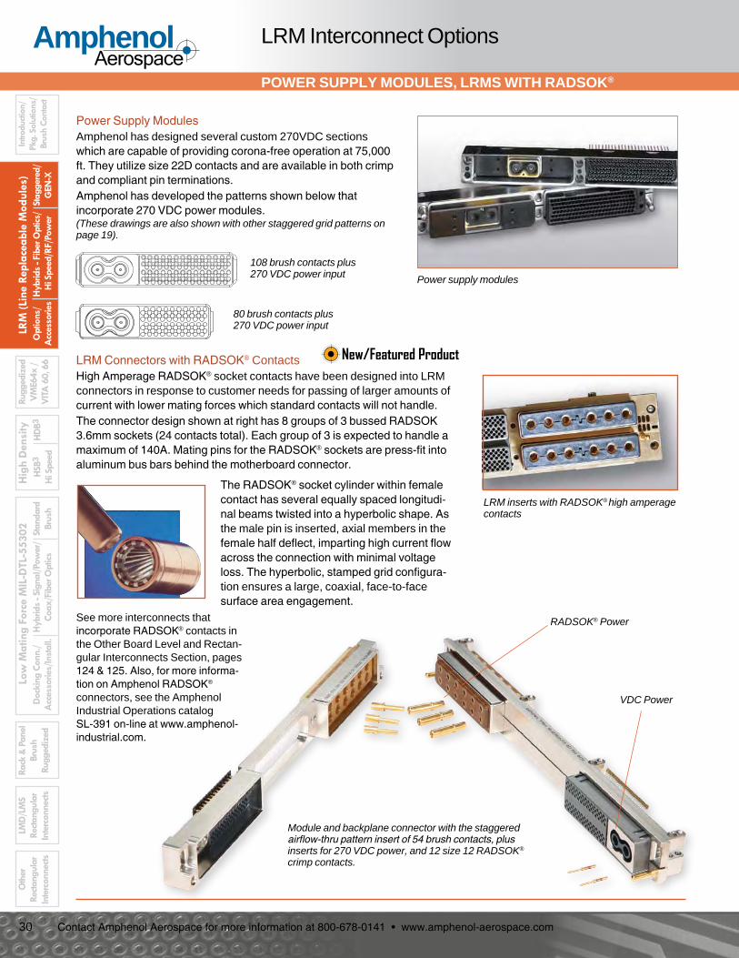
POWER SUPPLY MODULES, LRMS WITH RADSOK®
LRM Interconnect Options
Power supply modules
Power Supply ModulesAmphenol has designed several custom 270VDC sections which are capable of providing corona-free operation at 75,000 ft. They utilize size 22D contacts and are available in both crimp and compliant pin terminations.Amphenol has developed the patterns shown below that incorporate 270 VDC power modules.(These drawings are also shown with other staggered grid patterns on page 19).
LRM inserts with RADSOK® high amperage contacts
108 brush contacts plus 270 VDC power input
80 brush contacts plus 270 VDC power input
LRM Connectors with RADSOK® ContactsHigh Amperage RADSOK® socket contacts have been designed into LRM connectors in response to customer needs for passing of larger amounts of current with lower mating forces which standard contacts will not handle.The connector design shown at right has 8 groups of 3 bussed RADSOK 3.6mm sockets (24 contacts total). Each group of 3 is expected to handle a maximum of 140A. Mating pins for the RADSOK® sockets are press-fit into aluminum bus bars behind the motherboard connector.
The RADSOK® socket cylinder within female contact has several equally spaced longitudi-nal beams twisted into a hyperbolic shape. As the male pin is inserted, axial members in the female half deflect, imparting high current flow across the connection with minimal voltage loss. The hyperbolic, stamped grid configura-tion ensures a large, coaxial, face-to-face surface area engagement.
See more interconnects that incorporate RADSOK® contacts in the Other Board Level and Rectan-gular Interconnects Section, pages 124 & 125. Also, for more informa-tion on Amphenol RADSOK® connectors, see the Amphenol Industrial Operations catalog SL-391 on-line at www.amphenol-industrial.com.
Module and backplane connector with the staggered airflow-thru pattern insert of 54 brush contacts, plus inserts for 270 VDC power, and 12 size 12 RADSOK® crimp contacts.
RADSOK® Power
VDC Power
New/Featured Product
31
AmphenolAerospace
Contact Amphenol Aerospace for more information at 800-678-0141 • www.amphenol-aerospace.com
LRM (Line Replaceable M
odules)Staggered/
GEN
-X
Hybrids - Fiber O
ptics/ H
i Speed/RF/Power
Options/
Accessories
High D
ensityH
DB 3
HSB 3
Hi Speed
Low M
ating Force MIL-D
TL-55302Standard
BrushH
ybrids - Signal/Power/
Coax/Fiber Optics
Rack & Panel
Brush Ruggedized
Docking Conn./
Accessories/Install.
LMD
/LMS
Rectangular Interconnects
Other
Rectangular Interconnects
Introduction/Pkg. Solutions/Brush Contact
Ruggedized V
ME 64x/
VITA
60, 66
NEW LRMS PROVIDE HIGHER SPEED DATA TRANSFERENCE
Hi-Speed LRM Connectors
Amphenol’s LRM connectors meet today’s need for high speed interconnects for harsh environments. Constantly evolving and striving to meet the needs of higher data transfer rates within a board level product, Amphenol has developed LRM’s to meet this challenge. These LRMs are designed, or can be configured, to achieve data rates up to 6.25 Gb/s and include all the features of our rugged and reliable staggered grid LRM series:• Brush contact interface • ESD protection (Level 2 flight line classification)• Connector float• Guide pins and polarization keys• Metal shells• Modular design (hybrid configuration available)• Accepts wide range of board packages• Accomodations for custom modular offsetsIn addition, the new GigaStakTM, GigaStak-LGTM and DigiStakTM Series incorporate Amphenol’s cStackTM solderless termination technology (see page 35 for details). VersatilityUnique flex and cStack terminations accommodate a variety of mounting configurations and a wide range of board packages. Connectors can terminate in a variety of ways: • “traditional” 2 board/heatsink package• to one or both sides of a single board • as an offset board packageDigiStak module connectors allow mating to existing configura-tions of backplane connectors (users can upgrade solder termina-tion module connectors to the solderless cStack termination).
The Hi-Speed Family of LRM Connectors and associated data rates includes:• GigastakTM - 6.25 Gb/s• Gigastak LGTM - 3.125 Gb/s• DigistakTM & Digistak-XTM - 3.125 Gb/s• Standard Staggered Grid - 1.25 Gb/s
Hybrid Connector that has GigaStak-LGTM and DigiStakTM Inserts , shown on Testing Boards
DigiStakTM
GigaStak LGTM
Insert for RF or Power contacts
New/Featured Product
32
AmphenolAerospace
Contact Amphenol Aerospace for more information at 800-678-0141 • www.amphenol-aerospace.com
LRM
(Lin
e Re
plac
eabl
e M
odul
es)
Stag
gere
d/
GEN
-X
Hyb
rids
- Fib
er O
ptics
/ H
i Spe
ed/R
F/Po
wer
O
ptio
ns/
Acc
esso
ries
Hig
h D
ensi
tyH
DB3
H
SB3
Hi S
peed
Low
Mat
ing
Forc
e M
IL-D
TL-5
5302 St
anda
rd
Brus
hH
ybrid
s - S
igna
l/Pow
er/
Coax
/Fib
er O
ptics
Rack
& P
anel
Br
ush
Rugg
ediz
edD
ocki
ng C
onn.
/ A
cces
sorie
s/In
stal
l.
Intro
ducti
on/
Pkg.
Sol
utio
ns/
Brus
h Co
ntac
t
LMD
/LM
S Re
ctang
ular
In
terc
onne
cts
Oth
er
Recta
ngul
ar
Inte
rcon
nects
Rugg
ediz
ed
VM
E64x
/
VITA
60,
66
GIGASTAKTM- THE HIGHEST DENSITY HI-SPEED CONNECTOR
Hi-Speed LRMs
GigaStak Features:• Hi-Speed connector designed for both single ended and
differential signals• Supports data rates of 6.25 Gb/s• High density providing 30 differential signals per linear inch• Designed for 100 ohm differential impedance• Optimized cross-talk
Giga1100110100100
01100110011001101
takBuilt for speed
24 Differential Pair*
GigaStak Patterns
36 Differential Pair*
48 Differential Pair*
60 Differential Pair
Validation testing has been performed through both simulation (CST Microwave Studio) and actual testing of production connectors. Test reports, touchstone fles and hardware are available for review.
GigaStak 60 Differential Pair Insert with ESD Shield Exploded and Enlarged Section
Differential Pairs
Designated Ground Contact Rows
ENLARGED VIEW
Shielding Ground Blades
ESD Shield
GigaStakTM Module Unassembled
Amphenol has taken the proven and highly reliable LRM Brush connector and incorporated the cStackTM termination technology - giving the user hi-speed signal options up to 6.25 Gb/s and a solderless termination to their CCA.Through strategic placement of signal and ground contacts, each insert arrangement is optimized for the perfect balance of impedance control and cross-talk mitigation for a given data rate.
* Consult Amphenol for availability.
GigaStakTM Backplane Connector
New/Featured Product
33
AmphenolAerospace
Contact Amphenol Aerospace for more information at 800-678-0141 • www.amphenol-aerospace.com
LRM (Line Replaceable M
odules)Staggered/
GEN
-X
Hybrids - Fiber O
ptics/ H
i Speed/RF/Power
Options/
Accessories
High D
ensityH
DB 3
HSB 3
Hi Speed
Low M
ating Force MIL-D
TL-55302Standard
BrushH
ybrids - Signal/Power/
Coax/Fiber Optics
Rack & Panel
Brush Ruggedized
Docking Conn./
Accessories/Install.
LMD
/LMS
Rectangular Interconnects
Other
Rectangular Interconnects
Introduction/Pkg. Solutions/Brush Contact
Ruggedized V
ME 64x/
VITA
60, 66
GIGASTAK-LGTM
Hi-Speed LRMs
GigaStak LG Features:• Hi-Speed connector designed for differential signals• Supports data rates of 3.125 Gb/s• Current Design has 8 differential pairs• Provides 11 differential signals per linear inch• Designed for 100 ohm differential impedance• Optimized cross-talk
The GigaStak-LGTM inserts provide hi-speed data transfer-ence, utilzes cStack solderless termination, and can be combined with low speed signal contacts, as shown in the hybrid connector photo below.
23 Differential Pairs
GigaStak LG Patterns GigaStak-LGTM Inserts with 8 Hi-Speed Differential Pairs
GigaStak-LG Inserts with 8 Hi-Speed Differential Pairs Packaged with Staggered Grid Inserts with Low Speed Signal Contacts
Combined GigaStak-LG and DigiStak Insert (see next page for DigiStak description)
GigaStak-LG
DigiStak
8 Differential Pairs and 108 Digital Contacts
New/Featured Product
34
AmphenolAerospace
Contact Amphenol Aerospace for more information at 800-678-0141 • www.amphenol-aerospace.com
LRM
(Lin
e Re
plac
eabl
e M
odul
es)
Stag
gere
d/
GEN
-X
Hyb
rids
- Fib
er O
ptics
/ H
i Spe
ed/R
F/Po
wer
O
ptio
ns/
Acc
esso
ries
Hig
h D
ensi
tyH
DB3
H
SB3
Hi S
peed
Low
Mat
ing
Forc
e M
IL-D
TL-5
5302 St
anda
rd
Brus
hH
ybrid
s - S
igna
l/Pow
er/
Coax
/Fib
er O
ptics
Rack
& P
anel
Br
ush
Rugg
ediz
edD
ocki
ng C
onn.
/ A
cces
sorie
s/In
stal
l.
Intro
ducti
on/
Pkg.
Sol
utio
ns/
Brus
h Co
ntac
t
LMD
/LM
S Re
ctang
ular
In
terc
onne
cts
Oth
er
Recta
ngul
ar
Inte
rcon
nects
Rugg
ediz
ed
VM
E64x
/
VITA
60,
66
DIGISTAKTM AND DIGISTAK-XTM
Hi-Speed LRMs
DigiStak Features:• Designed to improve data rates in existing
staggered grid LRM inserts• Supports data rates of 3.125 Gb/s• Configurable for up to 20 differential pairs per
linear inch• Designed for 100 ohm differential impedance• Optimized cross-talk
DigiStak-X Features:• Designed to improve data rates in existing
GEN-X LRM inserts• Supports data rates of 3.125 Gb/s• Configurable for up to 20 differential pairs per
linear inch• Designed for 100 ohm differential impedance• Optimized cross-talk
.150 TYP( 3X .050 )
.150 TYP( 3X .050 )
.050TYP
.050 TYP
.050 TYP
.100 TYP
ConnectorCenterline
.075TYP
All dimensions in inches.
STAGGEREDThe DigiStak uses standard staggered grid insert pattern shown at right. (Pages 19 and 20 show the arrangements of staggered grid connectors which are also available in the Digistak connector).
DigiStakTM Hi-Speed LRM InsertsThe DigiStakTM connector provides the standard staggered grid LRM pattern in a hi-speed connector that utilizes cStack solderless termination.
DigiStak-XTM Hi-Speed LRM InsertsThe DigiStak-XTM connector provides the GEN-X grid LRM pattern in a hi-speed connector that utilizes cStack solderless termination.
The DigiStak-X uses GEN-X LRM grid pattern shown at right (Page 26 shows the arrange-ments of GEN-X grid connectors which are also available in the Digistak-X connector.
.060Spacing
.070
.035
.0375 Offset.075
.430
All dimensions in inches.
GEN-X
360 Pin DigiStak Module Connector
(2 sides of same connector)
New/Featured Product
35
AmphenolAerospace
Contact Amphenol Aerospace for more information at 800-678-0141 • www.amphenol-aerospace.com
LRM (Line Replaceable M
odules)Staggered/
GEN
-X
Hybrids - Fiber O
ptics/ H
i Speed/RF/Power
Options/
Accessories
High D
ensityH
DB 3
HSB 3
Hi Speed
Low M
ating Force MIL-D
TL-55302Standard
BrushH
ybrids - Signal/Power/
Coax/Fiber Optics
Rack & Panel
Brush Ruggedized
Docking Conn./
Accessories/Install.
LMD
/LMS
Rectangular Interconnects
Other
Rectangular Interconnects
Introduction/Pkg. Solutions/Brush Contact
Ruggedized V
ME 64x/
VITA
60, 66
CSTACKTM TECHNOLOGY
Hi-Speed LRMs
Side “A” Bolster
Mounting Screws
Side “B” Bolster
Side “A” Dielectric Film
Side “A” Interposer Assembly
Side “A” Interposer Assembly
Spring-clip Contacts
nterposer y
ip
nterposer
p
Side “B” DielectricFilm
Threaded Bossesfor Mounting Screws
Module Insert Assemblywith PCB Tail BrushContacts
Matched ImpedanceMultilayer Flex
FR4 Flex Stiffener/Support
Interposer Gasket(Optional)
Alignment Pin(Qty. 2 per Bolsteron Opposite Ends)
Anatomy of cStackTM Technology
cStackTM Wafer (Solderless Surface Mount Contacts)
High Performance Brush Contacts
Flex Circuitry
Bolster Plate (Stainless Steel Plate that Compresses cStack Contacts)
Fasteners (Captive Hardware for Mounting cStack to Board)
cStackTM Technology for Hi-Speed LRM Connectors
cStackTM TerminationGigaStakTM, GigaStak-LGTM, DigiStakTM and DigiStak-XTM series incorporate Amphenol’s cStackTM termination which provides the following features and benefits:• Flex circuit assemblies that provide high speed, impedance
controlled performance with high signal integrity.• Flex can be electrically and mechanically customized to fit
system specifications.• Allows solderless interconnection between flex and board,
eliminating a principal reliability problem with traditional flex assemblies.
• Standard and customized hardware are available which allow fast, solderless interconnection with only screw attachment to boards. Hardware uses captive attachment screws, eliminating loose component pieces.
Enlarged view of cStackTM Contact
See more information on Flex Circuitry in the Other Rectangular Interconnects Section page 121 of this catalog.
New/Featured Product
36
AmphenolAerospace
Contact Amphenol Aerospace for more information at 800-678-0141 • www.amphenol-aerospace.com
LRM
(Lin
e Re
plac
eabl
e M
odul
es)
Stag
gere
d/
GEN
-X
Hyb
rids
- Fib
er O
ptics
/ H
i Spe
ed/R
F/Po
wer
O
ptio
ns/
Acc
esso
ries
Hig
h D
ensi
tyH
DB3
H
SB3
Hi S
peed
Low
Mat
ing
Forc
e M
IL-D
TL-5
5302 St
anda
rd
Brus
hH
ybrid
s - S
igna
l/Pow
er/
Coax
/Fib
er O
ptics
Rack
& P
anel
Br
ush
Rugg
ediz
edD
ocki
ng C
onn.
/ A
cces
sorie
s/In
stal
l.
Intro
ducti
on/
Pkg.
Sol
utio
ns/
Brus
h Co
ntac
t
LMD
/LM
S Re
ctang
ular
In
terc
onne
cts
Oth
er
Recta
ngul
ar
Inte
rcon
nects
Rugg
ediz
ed
VM
E64x
/
VITA
60,
66
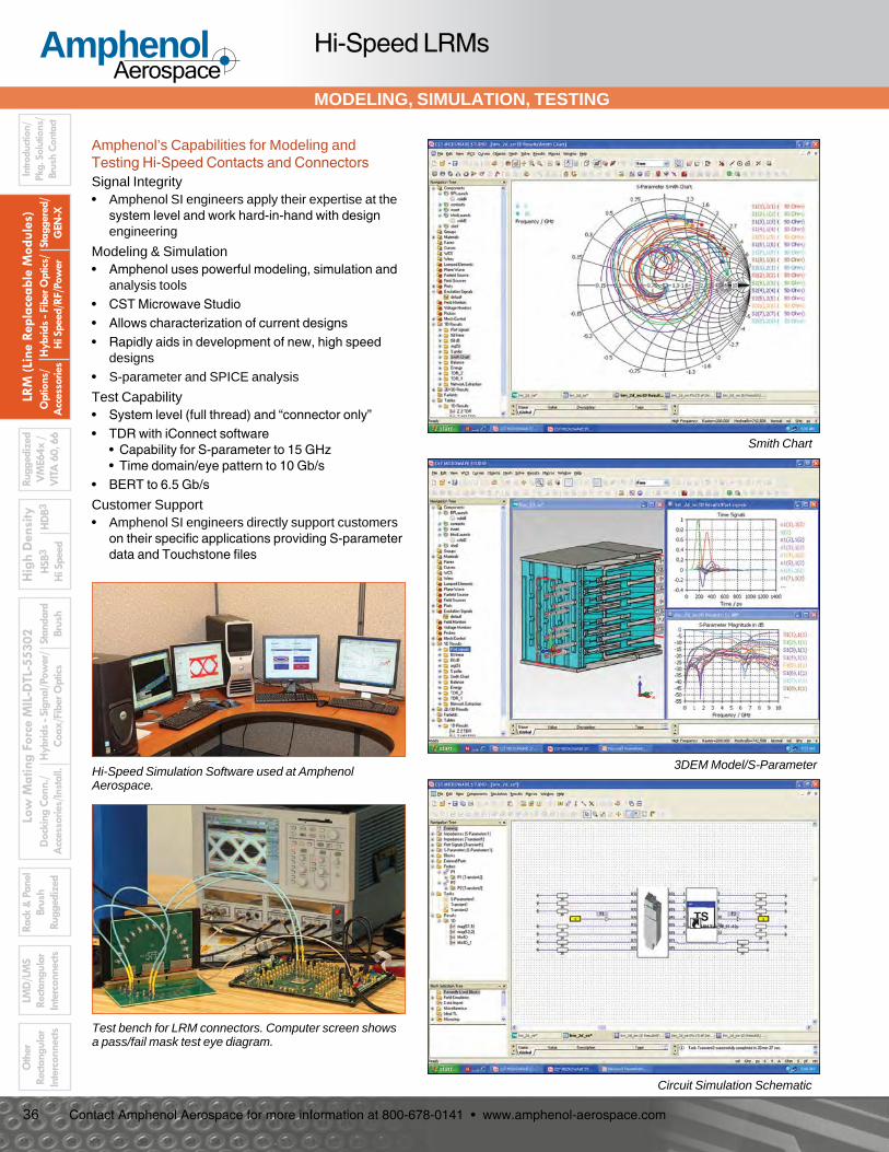
MODELING, SIMULATION, TESTING
Hi-Speed LRMs
Test bench for LRM connectors. Computer screen shows a pass/fail mask test eye diagram.
Hi-Speed Simulation Software used at Amphenol Aerospace.
Amphenol’s Capabilities for Modeling and Testing Hi-Speed Contacts and ConnectorsSignal Integrity• Amphenol SI engineers apply their expertise at the
system level and work hard-in-hand with design engineering
Modeling & Simulation• Amphenol uses powerful modeling, simulation and
analysis tools• CST Microwave Studio• Allows characterization of current designs• Rapidly aids in development of new, high speed
designs• S-parameter and SPICE analysis
Test Capability• System level (full thread) and “connector only”• TDR with iConnect software
• Capability for S-parameter to 15 GHz • Time domain/eye pattern to 10 Gb/s
• BERT to 6.5 Gb/s
Customer Support• Amphenol SI engineers directly support customers
on their specific applications providing S-parameter data and Touchstone files
Smith Chart
3DEM Model/S-Parameter
Circuit Simulation Schematic
37
AmphenolAerospace
Contact Amphenol Aerospace for more information at 800-678-0141 • www.amphenol-aerospace.com
LRM (Line Replaceable M
odules)Staggered/
GEN
-X
Hybrids - Fiber O
ptics/ H
i Speed/RF/Power
Options/
Accessories
High D
ensityH
DB 3
HSB 3
Hi Speed
Low M
ating Force MIL-D
TL-55302Standard
BrushH
ybrids - Signal/Power/
Coax/Fiber Optics
Rack & Panel
Brush Ruggedized
Docking Conn./
Accessories/Install.
LMD
/LMS
Rectangular Interconnects
Other
Rectangular Interconnects
Introduction/Pkg. Solutions/Brush Contact
Ruggedized V
ME 64x/
VITA
60, 66
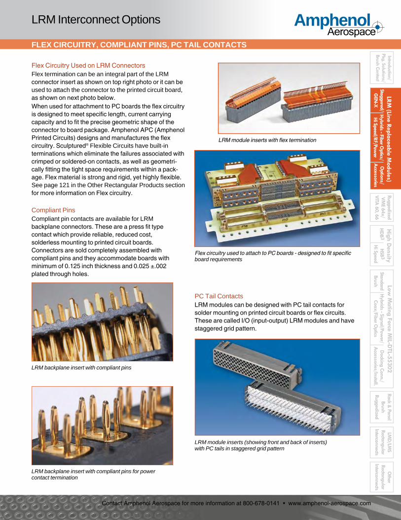
LRM module inserts with flex termination
Flex circuitry used to attach to PC boards - designed to fit specific board requirements
Flex Circuitry Used on LRM ConnectorsFlex termination can be an integral part of the LRM connector insert as shown on top right photo or it can be used to attach the connector to the printed circuit board, as shown on next photo below.When used for attachment to PC boards the flex circuitry is designed to meet specific length, current carrying capacity and to fit the precise geometric shape of the connector to board package. Amphenol APC (Amphenol Printed Circuits) designs and manufactures the flex circuitry. Sculptured® Flexible Circuits have built-in terminations which eliminate the failures associated with crimped or soldered-on contacts, as well as geometri-cally fitting the tight space requirements within a pack-age. Flex material is strong and rigid, yet highly flexible. See page 121 in the Other Rectangular Products section for more information on Flex circuitry.
Compliant PinsCompliant pin contacts are available for LRM backplane connectors. These are a press fit type contact which provide reliable, reduced cost, solderless mounting to printed circuit boards. Connectors are sold completely assembled with compliant pins and they accommodate boards with minimum of 0.125 inch thickness and 0.025 ±.002 plated through holes.
LRM backplane insert with compliant pins
LRM module inserts (showing front and back of inserts) with PC tails in staggered grid pattern
PC Tail ContactsLRM modules can be designed with PC tail contacts for solder mounting on printed circuit boards or flex circuits.These are called I/O (input-output) LRM modules and have staggered grid pattern.
FLEX CIRCUITRY, COMPLIANT PINS, PC TAIL CONTACTS
LRM Interconnect Options
LRM backplane insert with compliant pins for power contact termination
38
AmphenolAerospace
Contact Amphenol Aerospace for more information at 800-678-0141 • www.amphenol-aerospace.com
LRM
(Lin
e Re
plac
eabl
e M
odul
es)
Stag
gere
d/
GEN
-X
Hyb
rids
- Fib
er O
ptics
/ H
i Spe
ed/R
F/Po
wer
O
ptio
ns/
Acc
esso
ries
Hig
h D
ensi
tyH
DB3
H
SB3
Hi S
peed
Low
Mat
ing
Forc
e M
IL-D
TL-5
5302 St
anda
rd
Brus
hH
ybrid
s - S
igna
l/Pow
er/
Coax
/Fib
er O
ptics
Rack
& P
anel
Br
ush
Rugg
ediz
edD
ocki
ng C
onn.
/ A
cces
sorie
s/In
stal
l.
Intro
ducti
on/
Pkg.
Sol
utio
ns/
Brus
h Co
ntac
t
LMD
/LM
S Re
ctang
ular
In
terc
onne
cts
Oth
er
Recta
ngul
ar
Inte
rcon
nects
Rugg
ediz
ed
VM
E64x
/
VITA
60,
66
ELECTROSTATIC DISCHARGE (ESD) PROTECTION
LRM Interconnects with ESD Protection
Amphenol has developed cylindrical and rectangular connectors which protect sensitive components from Electrostatic Discharge (ESD) without diodes, varis-tors, gas tubes, or “experimental” semiconductive materials.These connectors utilize the Faraday Cage principal to shunt electrostatic discharge events to the conductive enclosure on which the connector is mounted, thus never allowing the high voltage, high current discharge event to reside on any contacts.The ESD protected connectors have the same physical envelope as their standard counterparts, and do not require special mounting or terminating techniques. All of the contacts remain fully functional, and electrical characteristics such as capacitance are not affected.• LRM Connectors with ESD protection have the
following features and benefits:• Connector envelope is identical to unprotected
design for most applications• Exceeds protection requirements of IEC 801-2 and
MIL-STD-1686: • Ensures that all components within a conductive
enclosure are not subjected to more than 10V during electrostatic discharges between –26 KV and +26 KV
• Voltage observed on contacts during ESD events: <10V (at 1 megohm)
• Current observed on contacts during ESD events: < 100 milliamperes (at 2 ohms)
• Response time is instantaneous (voltage and current are maximum values)
• Maximum ESD voltage - tested to ±26KV• No capacitive loading• Eliminates the need for discrete components (such
as diodes) and maximizes printed circuit board real estate for equipment housed in conductive enclosures which require ESD protection as freestanding units
• Operating voltage of connectors not effected for most designs
• Pulse life - infiniteESD protection is standard on the Amphenol Rugge-dized VME64x connectors (see page 43) and offers all the above features and benefits.There are many drop-in replacement ESD protected connectors for retrofitting existing programs which have a conductive enclosure and require ESD protec-tion as free-standing equipment.
ESD testing on LRM rectangular connector (actual photo)
What is Electrostatic Discharge (ESD)?Electrostatic Discharge is the rapid transfer of a static electric charge from one body to another. A static electric charge consists of either a surplus or depletion of electrons on a body, which gives that body a potential or voltage relative to ground (or an-other body). The discharge is extremely fast (less than 1 nano-second risetime) and the current flow may exceed 100 amps!Static electricity is normally the result of two materials transfer-ring charges when rubbed or separated, such as shoes scuffing across a dry carpet, or sheets of untreated plastic being separat-ed. This phenomena is commonly referred to as the triboelectric effect.The voltage developed due to the triboelectric effect depends on the materials involved, the quantity and type of contact, and relative humidity. In a dry environment a person can accumu-late a charge of up to 25 KV. In a moist environment a person’s potential is reduced due to the effect of moisture on the insulating properties of materials.
What is a Faraday Cage?A Farady cage is a conductive enclosure. It may be solid in form such as a sheet-metal encloser, or it may be full of apertures, such as a wire cloth box. When a charge is placed on a faraday cage the electrons which make up the charge, having like polar-ity, try to position themselves as far as possible from each other. This places the electrons on the outer surface of the enclosure, leaving the inner surface uncharged. The charge on the outer surface does not induce a charge on any neutral object inside of the faraday cage, and therefore does not try to transfer itself onto the internal object. Neutral objects (such as IC’s) inside of a faraday cage are thereby protected from ESD activity external to the faraday cage.The voltage and current observed on neutral objects within a fara-day cage during ESD events are due to the secondary effects of ESD. These include Electromagnetic Interference (EMI), magnet-ic and electrical field coupling. The faraday cage of the Amphenol ESD protected connectors has been designed to minimize these effects.The Faraday cage on Amphenol ESD protected connectors inter-cepts electrostatic discharges from the contacts in the unmated state, while maintaining each contact’s isolation when the connec-tor is mated.
Publication L-2075, “ESD Attenuation Test Procedure for Connectors with Faraday Cage Protective Structures” is available as a reference document. Contact Amphenol Aerospace for any further information on ESD protection connectors.
39
AmphenolAerospace
Contact Amphenol Aerospace for more information at 800-678-0141 • www.amphenol-aerospace.com
LRM (Line Replaceable M
odules)Staggered/
GEN
-X
Hybrids - Fiber O
ptics/ H
i Speed/RF/Power
Options/
Accessories
High D
ensityH
DB 3
HSB 3
Hi Speed
Low M
ating Force MIL-D
TL-55302Standard
BrushH
ybrids - Signal/Power/
Coax/Fiber Optics
Rack & Panel
Brush Ruggedized
Docking Conn./
Accessories/Install.
LMD
/LMS
Rectangular Interconnects
Other
Rectangular Interconnects
Introduction/Pkg. Solutions/Brush Contact
Ruggedized V
ME 64x/
VITA
60, 66
TEST PROBE KITS
LRM Accessories and Tools
Test probe for brush contact in LRM backplane
Test probe for brush contact in LRM module
Test Probe Kit - For use with Amphenol Brush Contacts in LRM ConnectorsAmphenol supplies a test probe kit especially designed for probing brush contacts to insure that they are properly wired within a connector. It consists of a plastic holder, insert, and two contacts which are usable for either the backplane or module connector. It is suggested that the user buy two kits if they are using connectors of two genders. The kits are not convertible after assembly.Instructions for use of Backplane Test Probe - Slide the insert back over the wire, and crimp contact on. Follow crimping procedure below. Then snap the insert contact assembly into the holder.Instructions for use of Module Test Probe - Slide holder over wire, and then crimp contact. Follow crimping procedure below. Slide the insert on the contact and seat it against the shoulder. Slide the holder forward and snap it onto the insert.Crimping Procedure - Using accepted industry procedures, strip wire end to be terminated 1/8 to 5/32 inches. Care should be taken not to nick wire strands. Assemble the M22520/2-01 crimp tool and M22520/2-27 positioner and place tool selector in correct setting for wire size. Selected wire size must not have an insulation diameter greater than .062 for the module probe and not greater than .038 for the backplane probe.
AWG 22 24 26 28
SEL 5 4 3 2
Insert stripped wire end into contact wire well. Strands should be visible in wire well inspection hole. Bottom contact and wire assembly in positioner and close handles of crimp tool to complete crimp. Handles will not open unless full crimping cycle has been completed.Part number for ordering test probe kit is 11-10400-23.
ATTENTION:Probing brush contacts with anything other than a brush contact may damage or degrade the brush contact performance.
Test probe kit 11-10400-23 components
40
AmphenolAerospace
Contact Amphenol Aerospace for more information at 800-678-0141 • www.amphenol-aerospace.com
LRM
(Lin
e Re
plac
eabl
e M
odul
es)
Stag
gere
d/
GEN
-X
Hyb
rids
- Fib
er O
ptics
/ H
i Spe
ed/R
F/Po
wer
O
ptio
ns/
Acc
esso
ries
Hig
h D
ensi
tyH
DB3
H
SB3
Hi S
peed
Low
Mat
ing
Forc
e M
IL-D
TL-5
5302 St
anda
rd
Brus
hH
ybrid
s - S
igna
l/Pow
er/
Coax
/Fib
er O
ptics
Rack
& P
anel
Br
ush
Rugg
ediz
edD
ocki
ng C
onn.
/ A
cces
sorie
s/In
stal
l.
Intro
ducti
on/
Pkg.
Sol
utio
ns/
Brus
h Co
ntac
t
LMD
/LM
S Re
ctang
ular
In
terc
onne
cts
Oth
er
Recta
ngul
ar
Inte
rcon
nects
Rugg
ediz
ed
VM
E64x
/
VITA
60,
66
REMOVAL, REPLACEMENT & INSERTION TOOLS
LRM Accessories and Tools, cont.
Brush Contact Removal, Replacement and Insertion for Backplane Staggered Grid ConnectorsContacts with solder tails within backplane LRM connectors with stag-gered grid are not removable or replaceable. User must replace the insert assembly.Compliant tail type contacts within backplane LRM connectors with staggered grid are removable and replaceable.Instructions for removal of compliant contacts: From the back of PC board side, push contact out through the front of the connector assembly with contact removal tool #10-507941-1. Instruction for replacement/insertion of compliant contacts: Using tweezers or fingers, carefully place the replacement contact, tail first, into the appropriate contact cavity in the front of the connector. Tweezer tip must not enter sleeve. Push contact into the cavity with a flat edged rod of suitable diameter to cover entire contact sleeve circumference until contact sleeve is flush with adjacent contacts. Do not push against wires or bend sleeve.
270 VDC Power Module Removal, Replacement and Insertion for Backplane Staggered Grid Connectors270 VDC power modules can be removed and replaced within the power insert of an LRM connector.Instructions: Using removal tool #10507924-1 with plunger retracted, push tool down over the power module from the mating end until reten-tion tines are released. Use plunger end of tool to push power module out of the rear the connector.The power module may be re-installed by hand by pushing it from the rear of the connector. Push it forward until the retention clips snap into the power insert cavity of the shell.The size 22D power contacts within the power modules are installed and removed with tool M81969/14-01.
Removal tool 10-507941-1 for removing compliant contacts from LRM backplanes
Removal tool 10-507924-1 (plunger retracted) for removing 270 VDC power modules from LRM backplanes
For Module Staggered Grid Connectors:Contacts within module LRM connectors with staggered grid are not removable or replace-able. User must replace the insert assembly.
Exploded view - tool 10-507924-1 has removed power module from backplane. (size 22D contacts shown removed)
41
AmphenolAerospace
Contact Amphenol Aerospace for more information at 800-678-0141 • www.amphenol-aerospace.com
LRM (Line Replaceable M
odules)Staggered/
GEN
-X
Hybrids - Fiber O
ptics/ H
i Speed/RF/Power
Options/
Accessories
High D
ensityH
DB 3
HSB 3
Hi Speed
Low M
ating Force MIL-D
TL-55302Standard
BrushH
ybrids - Signal/Power/
Coax/Fiber Optics
Rack & Panel
Brush Ruggedized
Docking Conn./
Accessories/Install.
LMD
/LMS
Rectangular Interconnects
Other
Rectangular Interconnects
Introduction/Pkg. Solutions/Brush Contact
Ruggedized V
ME 64x/
VITA
60, 66
Please fill out information below. Thank you for writing clearly. Fax to 607-563-5351, attention: LRM product marketing.
First Name Last Name Phone Number Date
Title Dept./Mail Stop Fax Number
Company Name Address
City State Zip Code Email Address
The following are questions to be considered when inquiring about Amphenol LRM/LRU Interconnects. The answers to these questions will help the Amphenol marketing and engineering team to determine the best board level interconnect to meet your particular needs.You can copy this page and write your comments on it, and then fax it back to Amphenol Aerospace, Sidney, NY. Include your name and company information at the bottom. Fax number: 607-563-5351, Attn: LRM product marketing. Or call Amphenol at 607-563-5011 and ask for technical information on LRM products.
Footprint Required:
Staggered, GEN-X, NAFI, UHD, Chevron, VME or other: _____________________________________________ ______________________________________________________________________________________