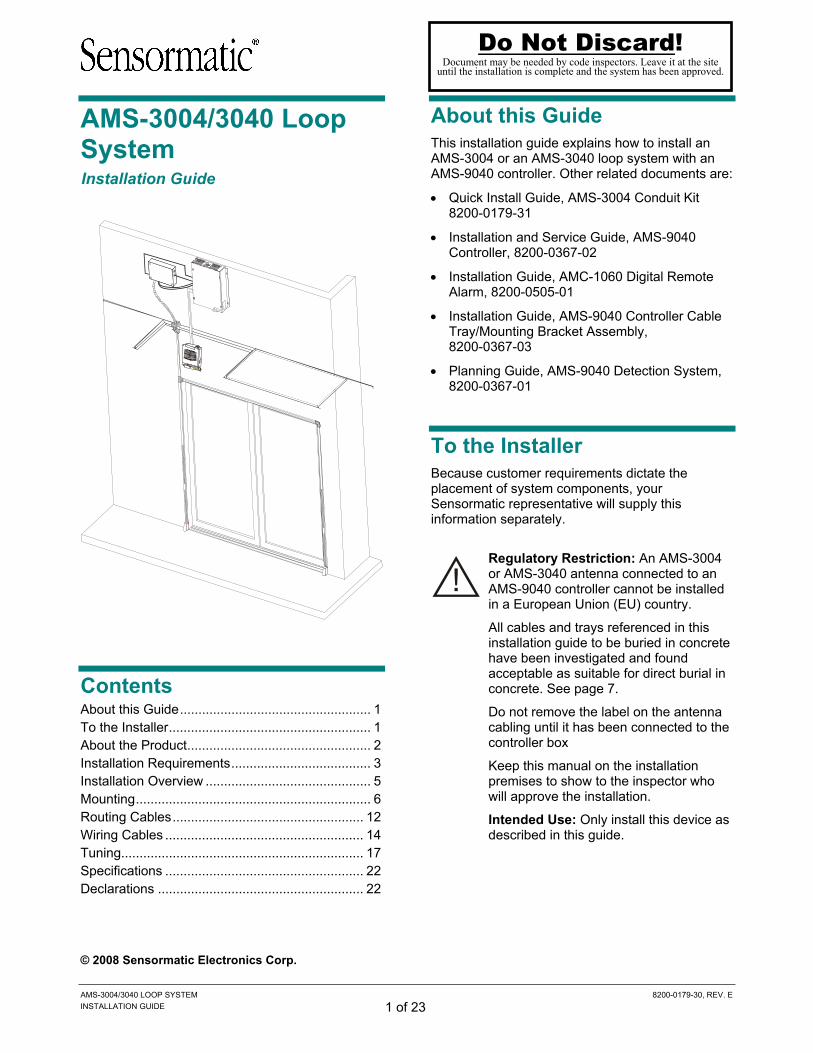
About this Guide This installation guide explains how to install an AMS-3004 or an AMS-3040 loop system with an AMS-9040 controller. Other related documents are:
To the Installer Because customer requirements dictate the placement of system components, your Sensormatic representative will supply this information separately.
Regulatory Restriction: An AMS-3004 or AMS-3040 antenna connected to an AMS-9040 controller cannot be installed in a European Union (EU) country.
All cables and trays referenced in this installation guide to be buried in concrete have been investigated and found acceptable as suitable for direct burial in concrete. See page 7.
Do not remove the label on the antenna cabling until it has been connected to the controller box
Keep this manual on the installation premises to show to the inspector who will approve the installation.
Intended Use: Only install this device as described in this guide.
Do Not Discard! Document may be needed by code inspectors. Leave it at the site
until the installation is complete and the system has been approved.
AMS-3004/3040 LOOP SYSTEM 8200-0179-30, REV. E INSTALLATION GUIDE 2 of 23
About the Product
Product Description An AMS-3004 system is a security label detection system that consists of the following equipment: an AMS-9040 controller, a transmitting loop cable, an intelligent capacitor board, two pairs of amorphous core receivers, a remote alarm, and a raceway kit that houses the receivers and the loop cable. An optional conduit kit (ZP3004-CONDUIT) that houses the loop cable in the floor is also available. An AMS-3040 system is similar to an AMS-3004 system except it uses a 68kHz version of the AMS-9040 controller and cap board. The AMS-3040 system requires a 68kHz hard tag (ZL31-68G).
AMS-3004 and AMS-3040 systems are similar to an AMS-3000 loop system except they use two pairs of amorphous core receivers instead of Rangers to cover wider exits and they use raceways instead of aluminum extrusions to house the cables.
Up to two loops (and exits) can be connected to an AMS-9040 controller but the loops must be configured to transmit alternately, not simultaneously.
The AMS-3004 and AMS-3040 have different exit coverages:
• The AMS-3004 covers exits 0.9m-2.4m (3-8ft) wide and up to 3.0m (10ft) high; the full detection field, however, is 1.8m (6ft) high.
• The AMS-3040 exit coverage is less than the AMS-3004 exit coverage.
Installation Features • Raceways have self-adhesive strip for easy
installation. • Raceways have snap-on covers to eliminate
“fishing” of cables through extrusions. • Loop cable can be buried in a narrow trench
without conduit, depending on local codes.
Service Features • Raceways have snap-on covers for easier
replacement of loop cable or receivers. • The intelligent cap board with a system ID
jumper allows the controller to initially configure itself for the antenna. The controller, however, will need to be adjusted with configurator software during tuning.
AMS-9040 controller Cap box
Remote alarm
Raceways
Amorphous core receivers (shown inside raceways)
AMS-3004/3040 LOOP SYSTEM 8200-0179-30, REV. E INSTALLATION GUIDE 3 of 23
Installation Requirements Equipment Required Basic setup requires the following equipment: • AMS-9040 controller (ZE9040 or ZE9040-68K) • Amorphous core receiver kit (ZSLOOP-AMRX) • Capacitor box kit (ZPL4-CAP or ZSL4-CAP-
68K) • Raceway kit (ZP3004-RW) • Remote alarm (ZP1060) • Hard tag (non-deactivateable Ultra•Max tag) • Ultra•Max low energy labels.
Advanced setup requires the following additional equipment: • Laptop with Windows® NT, Windows 2000, or
Windows XP operating software • RS-232 Ultra•Max programming cable • ADS 4 service configurator software.
Notes:
• Verify that all equipment has arrived. Ensure the system configuration is correct for the site.
• Unpack major components in a back room. At the install site, lay out parts in the order used. Do not clutter the aisle or cause a trip hazard.
Installer/Contractor • Have electrical work comply with the latest
national electrical code, national fire code, and all applicable local codes and ordinances.
• Coordinate work with other trades to avoid interference.
• Verify existing site conditions and coordinate with the owner’s representative and appropriate utilities as required.
• Obtain copies of all related plans, specifications, shop drawings and addenda to schedule and coordinate related work.
• Thoroughly review the project to ensure that all work meets or exceeds the above requirements. Bring alleged discrepancies to the attention of Sensormatic Electronics.
Safety Requirements WARNING—RISK OF ELECTRIC SHOCK! During installation, if the antenna must be left unattended, turn off power or cover high voltage components to prevent unauthorized access to hazardous voltages. WARNING—RISK OF ELECTRIC SHOCK! The ac power cord could be carrying 120Vac or 240Vac.
WARNING! Do not install this device where highly combustible or explosive products are stored or used. WARNING! The ac source must be a 2-wire type with ground. It also must be a 24-hour, unswitched outlet with less than 0.5Vac between neutral and ground.
WARNING: DO NOT compromise the structural integrity of the floor by cutting or removing rebar. Contractors must obtain approval for all proposed structural changes. All structural changes must meet national and local requirements.
WARNING! This device is not suitable for an IT power distribution system where impedance exists between neutral and protective earth contacts.
CAUTION: When using a power cord, install a socket-outlet near the controller in an easily accessible location. CAUTION: A 10A, 2-pole, ganged disconnect device, which also provides short circuit and overload protection, and has a minimum 3mm open circuit clearance, in accordance with the National Electric Code and applicable local codes must be installed by a licensed electrician at a location readily accessible to the equipment. CAUTION: DO NOT share the ac source with neon signs, motors, computers, cash registers, terminals, or data communications equipment. CAUTION: DO NOT use orange-colored outlets dedicated for computer equipment. CAUTION: Select the appropriate power cord based on the country of use.
AMS-3004/3040 LOOP SYSTEM 8200-0179-30, REV. E INSTALLATION GUIDE 4 of 23
Antenna Requirements • Whenever possible, keep the antennas at least
2.4m (8ft) away from noise sources such as computer monitors, TV’s, switching power supplies, and neon displays.
• For the minimum separation distance between adjacent loops, refer to the planning guide for the controller.
Implanted Medical Devices Although this anti-theft system complies with all applicable safety standards, place the system in such a way that customers: • do not linger near or lean on its antenna(s)
while making their purchase • are only directly in front of the antenna(s) while
exiting the checkout area. If the country’s language is different from English, apply “Anti-Theft” labels in the local language to the antennas. Labels are available from your local distribution center.
Tools Required For all installations:
Field strength meter (0101-0063-02)
Plastic sheeting at least 0.15mm (6 mil) thick (to protect nearby items from dust)
Hacksaw
PVC pipe cutter and solvent
Red permanent marker or chalk
Clear lacquer spray
Floor saw capable of cutting 3.2cm (1 1/4in) deep and safety goggles
Hammer and chisel
Power drill with 2, 6, 10, and 13mm (1/16, 1/4, 3/8 and 1/2 inch) bits
Hammer drill with 6.5mm (1/4in) and 9.6mm (3/8in) masonry drill bits
Phillips and slotted screwdrivers
0.4-1.5mm2 (16-22 AWG) and 1.5-2mm2 (14-16 AWG) wire strippers
Utility knife
Pliers
Ratchet and socket set
Wet vacuum and broom
Level
AMS-3004/3040 LOOP SYSTEM 8200-0179-30, REV. E INSTALLATION GUIDE 5 of 23
Installation Overview This document describes how to install all the parts of an AMS-3004 or AMS-3040 loop system except the AMS-9040 controller and the optional loop conduit. The installation procedures for the controller and the conduit kit are described in the manuals listed at the beginning of this document.
The installation of an AMS-3004 or AMS-3040 system occurs in four phases:
Phase 1: Mounting
Mount the controller
Install raceways around door and to ceiling
Cut floor and install conduit if necessary
Set jumpers and switches on cap box and mount on wall.
Phase 2: Routing
Route receiver cables to controller
Route loop cable to cap box
Phase 3: Wiring
Wire cap box and remote alarm to controller
Wire receivers to controller
Wire loop to cap box
Wire controller to cap box
Phase 4: Tuning
Tune cap board
Test and trouble-shoot system
CAUTION: An AMS-3040 system must have a 68kHz controller, a 68kHz capacitor board, and 68kHz tags. Failure to use the 68kHz version of all three items will result in the system not functioning properly. Also, 68kHz controllers, cap boards, and hard tags may not be used in 58kHz systems or the system will not function properly. You can identify 68kHz versions of the controller and cap board by stickers placed on the items that say “68KHz COMPATIBLE ONLY”.
Sticker
Cap Box
Controller
AMS-3004/3040 LOOP SYSTEM 8200-0179-30, REV. E INSTALLATION GUIDE 6 of 23
Mounting During the mounting phase of the installation, you should cut the floor first; the rest of the tasks can be done in any order.
• Cut the floor for the installation of the transmitter loop cable
• Mount the controller and its accessories
• Mount the raceways, transition pieces, and connectors with the amorphous receivers. The raceways can be mounted either onto the wall and door or inside the walls
• Mount the capacitor box
It is important that you mount the equipment close enough together so that all the cables reach and are not longer than they should be. In particular, the distance between the loop and the cap box should be kept as short as possible. The figure below shows how the general layout of a system. Note that the receiver cables are routed in and out of the cap box.
Cutting the Floor
The transmitter loop cable (P/N 0652-0278-01) must be routed 61cm (2ft) into the store under the floor. Before cutting the floor so that the transmitter loop cable can be buried, you must decide whether the loop cable will be in conduit or use direct burial.
Because the transmitter loop cable is burial-rated, the conduit kit is usually used where:
• Local code requires cable to be buried in conduit, or
• The site is under construction and the conduit kit makes it easier to install the cable later.
For instructions on installing the conduit kit, refer to the AMS-3004 Conduit Kit Quick Install Guide included with the kit.
To bury the cable directly, use a floor saw to make cuts 12mm (0.5in) deep by 8mm (0.3in) wide in the floor as shown. The loop cable exits the floor 1.3cm (0.5in) from the wall.
Receiver cables
Loop cables
2.4m (8ft) max
1.2m (4ft) max
8mm (0.3in)
8mm (0.3in)
8mm (0.3in)
0.6m (2ft)
(length depends on door width)
Small cuts at corners may be necessary to route cable around corner
Cuts should be 12mm (0.5in) deep
AMS-3004/3040 LOOP SYSTEM 8200-0179-30, REV. E INSTALLATION GUIDE 7 of 23
The transmitter loop cable assembly (P/N 0652-0278-01), which uses cable that is marked P/N 6002-0194-01, has been investigated and found suitable for direct burial in mortar and concrete.
An inspector may request the listing file number for the cable.
Table 1. Listing file numbers for transmitter cable
Sensormatic P/N Listing File Numbers*
Vendor
0652-0278-01 E118963 or E100316
Coleman
* The listing file number varies with the cable vendor and is printed on the cable.
Mounting the Controller
1. Select the location for the controller.
• Preferred location is in a hidden location, for example in the space above a drop-down ceiling. The controller is not for use in “Environmental Air Handling Space Other Than Ducts and Plenums” without the use of the Air Handling kit.
• Ensure the power cord can reach a power outlet.
• Ensure the controller can reach the cap box with the 13m (40ft) power and communication cables.
• Ensure cables from receivers can reach controller after being routed through the cap box.
2. Mount the controller cable tray/mounting bracket. Refer to the AMS-9040 Controller Cable Tray/Mounting Bracket Assembly Installation Guide for more information.
3. Mount the controller to the wall. Refer to the AMS-9040 Controller Installation and Service Guide for information. The cap box kit has M3.9X13 screws you can use.
Part Qty. Part Number Self-drilling M3.9x13 screws 4 5899-0108-01
4. Mount the AMC-1060 remote alarm. Refer to the AMC-1060 Digital Remote Alarm Installation Guide for more information.
Controller
AMS-3004/3040 LOOP SYSTEM 8200-0179-30, REV. E INSTALLATION GUIDE 8 of 23
Installing Raceways and Conduit
The parts in the raceway kit (ZP3004-RW) are shown above and listed in the table below.
Part Qty. Part Number Raceway 2.4m (8ft) 5 1410-0017-01 Cover clip 4 1410-0017-02 Flat elbow 2 1410-0017-03 Right angle tee 2 1410-0017-04 Internal corner elbow 2 1410-0017-05 External corner elbow 2 1410-0017-06 Floor housing 2 1410-0017-08 Self-drilling M2.9x9.5 screws 20 5899-0107-01 Self-drilling M3.9x13 screws 4 5899-0108-01 Drop ceiling housing 1 1410-0017-09 Towel 2 1600-0207-01 Alcohol pads 8 1600-0033
The procedure for installing the raceways and other cable housing parts is described below.
1. Detach the knockout on the bottom of the floor housing and screw the back of the floor housing to the wall on each side of the door. Ensure the knockout is over the spot where the loop cable will come out of the ground (about 1.3cm (0.5in) from the wall).
• For wood or metal, use the self-drilling, self-tapping M3.9x13 screws in the kit.
• For drywall, use 0.6cm (1/4in) hollow wall anchors and 2.5cm (1in) #8 screws (not supplied).
Raceway Cover clip
Flat elbow Right angle tee
Internal corner elbow External corner elbow
Drop-ceiling housing Floor housing
Floor housing back
Knockout
Loop cable
Floor housings
Drop-ceiling housing
Raceways
Right angle tee
Flat elbow
AMS-3004/3040 LOOP SYSTEM 8200-0179-30, REV. E INSTALLATION GUIDE 9 of 23
2. Measure and cut the vertical raceways to the correct length. Cut the raceways with the covers on. Ensure you allow room for the corner pieces above them. For distances greater than 2.4m (8ft), you will need an additional raceway and a cover clip.
3. Locate the four amorphous core receivers, which come in pairs of upper and lower receivers. The upper receiver has the receiver cable running along its length.
CAUTION: Use care when handling the receivers; bending or flexing them can cause them to crack and malfunction. The amorphous core receivers must be enclosed in raceways; they are too brittle to be free-standing.
4. Peel the paper from one side of the round white adhesive dots and place one dot on the side of each receiver. The white dots will keep the receivers from sliding in the raceways.
5. Peel the paper from the other side of the white adhesive dot and slip the long edge of the lower receiver under the edge about 1.3cm (0.5in) from the end of the raceway and snap it into the raceway. Ensure the white dot keeps the receiver from sliding. Repeat with the upper receiver.
6. Run the receiver cable up the raceway.
7. Repeat steps 1 through 6 with the other receivers.
8. Use the towel and alcohol pads included with the kit to clean the door jamb around the door.
9. Remove the backing on the adhesive tape on one of the raceways.
CAUTION: In the following step, the raceway must be carefully aligned before placing it on the doorway. The adhesive tape bonds immediately and, once attached, cannot be removed.
10. Ensure the raceway is oriented with the lower receiver at the bottom and put the bottom of the raceway against the top of the floor housing and slowly lay the raceway against the wall. Repeat for the raceway on the other side of the door.
Raceway with receivers inserted
White dot
Receiver
Raceway
AMS-3004/3040 LOOP SYSTEM 8200-0179-30, REV. E INSTALLATION GUIDE 10 of 23
11. To ensure the vertical raceways are secure, screw each vertical raceway to the door with two screws, one above and one below each receiver pair.
• For wood or metal surfaces, use the self-drilling, self-tapping M3.9x13 screws included with the kit.
• For drywall, use 0.6cm (1/4in) hollow wall anchors and 2.5cm (1in) #8 screws (not supplied).
12. Use screws to screw the back of the flat elbow and the back of the right angle tee above the vertical pieces.
• For wood or metal, use the self-drilling, self-tapping M3.9x13 screws included with kit.
• For drywall, use 0.6cm (1/4in) hollow wall anchors and 2.5cm (1in) #8 screws (not supplied).
13. Measure the distance between the raceway connectors above the door and cut the horizontal raceway.
14. Remove the adhesive backing on the horizontal raceway (s).
15. Attach the horizontal raceway to the door. Secure it to the door with two screws.
• For wood or metal, use the self-drilling, self-tapping M3.9x13 screws included with kit.
• For drywall, use 0.6cm (1/4in) hollow wall anchors and 2.5cm (1in) #8 screws (not supplied).
16. Screw the back of the drop ceiling housing to where the drop ceiling meets the wall. If the site has a hard ceiling instead of a drop ceiling, use the drop-ceiling housing anyway; it functions as a transition piece to the flex conduit. For hard ceilings, the entire housing is screwed to the wall under the ceiling and a hole is cut in the ceiling through the knockout.
Metal supports for drop-down ceiling tiles
Knockout
Back of drop ceiling housing
Screw
Top receiver
Floor housing
Screw
Bottom receiver
Receiver cable
AMS-3004/3040 LOOP SYSTEM 8200-0179-30, REV. E INSTALLATION GUIDE 11 of 23
17. Measure the distance from the right angle tee to the drop-ceiling housing and cut a raceway to that length.
18. Remove the adhesive backing and attach the raceway above the right angle tee.
19. Use a utility knife and pliers to remove the knockout on the floor housing insert and insert it into the floor housing. See the figure below.
Installing Antennas Inside Walls Alternatively, the antenna assemblies can be installed inside the walls instead of externally on the doorframe. The size limitations of the system (for 58kHz systems, 0.9m-2.4m (3-8ft) wide and up to 3.0m (10ft) high) refer to antenna size, so they should not be exceeded. The vertical raceway assemblies containing the Tx cable and the Rx antennas remain the same, while the floor housing and drop ceiling housing can be used but are not required.
Note: A loop cable installed in a wall must be enclosed in a mechanical enclosure.
1. Attach the vertical antenna assemblies completed during the “Installing Raceways and Conduit” section of this guide inside the wall next to the doorframe. Use the adhesive tape, and screws if needed, to ensure permanence. Make sure the raceway rests on the floor directly on top of where the Tx cable exits the floor, so there is no exposed cable. If there is exposed cable, use the floor housing.
2. For distances greater than 2.4m (8ft), you will need an additional raceway and a cover clip. The entire vertical run of Tx cable must be enclosed in the raceway.
3. Route the loop cable to the cap board in the vertical raceways and over the doorframe in the ceiling to form the “loop”. The cable must be enclosed in a mechanical enclosure; you can use the horizontal raceway or conduit.
4. Continue with the rest of the installation.
Floor housing
insert
Floor housing
cover
Knockout
AMS-3004/3040 LOOP SYSTEM 8200-0179-30, REV. E INSTALLATION GUIDE 12 of 23
Mounting the Cap Box
The cap box contains the capacitor board for the antenna. Although the cap boards for the AMS-3004 and AMS-3040 look virtually identical, they have different part numbers and are not interchangeable.
• AMS-3004 cap board – 0312-2159-01
• AMS-3040 cap board – 0312-3033-01
1. Select the location for the cap box.
• Preferred location is in a hidden location, for example in the space above a drop-down ceiling.
• A cap box must be within 2.4m (8ft) of the door loop.
2. Set the jumpers and switches on the cap board.
• Board ID jumper (AMS-3004 only) – set to AMS-3004, which is the default setting. Note: the Board ID for the AMS-3040 cap boards are hardwired internally.
• 9030 mode jumper – set jumper OUT (non-AMS-9030 mode).
• Address switch S1 – set to zero for single loop systems. For dual loop configurations, set one cap board to zero and the other to one.
3. Mount the cap box to the wall. The wall and mounting method must support 8.4kg (18.4lbs). The cap box kit has M3.9x13 self-drilling screws you can use, but you may need to supply hardware appropriate for the mounting surface (for example, drywall anchors).
Routing Cables Once all the equipment and raceways have been mounted, you can route the loop cable to the cap board and the receiver cable to the controller.
You will need the following parts in the cap board kit (ZPL4-CAP or ZSL4-CAP-68K):
Part Qty. Part Number Loop cable 1 0652-0278-01 Flex conduit 1.2m (4ft) 1 6010-0127-02 Flex conduit clamps 2 6010-0126-02
1. Route the 18m (60ft) loop cable in the cap board kit through the floor and raceways to the drop-ceiling housing. Use the cable clips in the raceways to hold the cable in place. Do not connect the cable to the cap box yet.
Board ID jumper
9030 mode jumper
Address switch S1
AMS-3004/3040 LOOP SYSTEM 8200-0179-30, REV. E INSTALLATION GUIDE 13 of 23
2. Route the cables from the receivers through the raceways to the drop-ceiling housing. The receiver cables do not go in the cable clips in the raceway. Do not connect the cables to the cap box yet.
3. Route the loop cable and receiver cables
through the 1.2m (4ft) length of flex conduit and flex conduit clamps to the cap box. If it is necessary, the flex conduit can be cut.
4. Attach the flex conduit to the drop-ceiling housing and the cap box using the flex conduit clamps.
5. Route the receiver cables back outside of the cap box. Use a knockout next to where it enters the cap box to prevent the receiver cables from getting near the high-voltage components on the cap board.
6. Route the receiver cables to the controller.
7. Close the raceway covers.
8. Snap on the T and splice covers.
Flex conduit
Receiver cables Flex conduit clamp
Strain- relief connector
Regulatorylabel
(on inside of box)
AMS-3004/3040 LOOP SYSTEM 8200-0179-30, REV. E INSTALLATION GUIDE 14 of 23
9. Snap on the covers for the drop-ceiling housings.
10. Apply anti-theft labels in the local language to the door frame adjacent to the raceway about 1.2m (4ft) above the floor on both sides. Labels in your local language (2412-0170-XX) can be ordered from your local distribution center.
Wiring Cables After you have routed the cables to the cap board and controller, you can connect the cables. The cables can be connected in any order.
When connecting the wires, use the following parts from the cap box kit to insulate the connections:
Part Qty/length Part Number Heat-shrink tubing 15cm (6in) 3121-0026-06 Teflon tubing (16G) 5.4cm (2in) 3121-0025-04 Teflon tubing (18G) 12cm (5in) 3120-0005 Strain-relief connectors 7 6010-0107-07
The strain-relief connectors should be used at every opening in the cap box and controller that a cable passes through.
WARNING—RISK OF ELECTRIC SHOCK! Unplug controller before connecting cables to controller.
Figure 1. Wiring diagram for 1-loop system
Table 2. Single loop cable connections Device Conn. Device Conn. Loop cable A Cap board A P1, P2 Right Rec. A Controller Aux Rx A Left Rec. A Controller Aux Rx B
P5 Controller Comm A Cap Board A P3 Controller Tx Ant A
Remote Alarm Comm Controller Comm C
Loop cable Remote alarm Receivers
Cap board
Controller
P2 P1 P3
P5
Ant A
Aux A,B
Comm AComm C
AMS-3004/3040 LOOP SYSTEM 8200-0179-30, REV. E INSTALLATION GUIDE 15 of 23
Notice that in Figure 2 the loops are connected to Tx Ant A and Tx Ant B. When the AMS-9040 controller powers up, it detects the type of cap board and antenna connected. When it detects two AMS-3004 cap boards, it transmits alternately on the Tx Ant A and Tx Ant B connectors only.
Figure 2. Wiring diagram for 2-loop system
Table 3. Dual loop cable connections Device Conn Device Conn. Loop cable A Cap board A P1, P2 Loop cable B Cap board B P1, P2 Right Rec. A Controller Aux Rx A Left Rec. A Controller Aux Rx B Right Rec. B Controller Aux Rx C Left Rec. B Controller Aux Rx D
P5 Controller Comm A Cap Board A P3 Controller Tx Ant A P5 Controller Comm B Cap Board B P3 Controller Tx Ant B
Remote Alarm A Controller Comm A Remote Alarm B Controller Comm C
Wiring Cap Box and Remote Alarm to Controller
To connect the remote alarm, use the cable supplied with the remote alarm. To connect the cap board, use the following cables from the cap box kit.
Part Qty Part Number Cap board power cable, 2 conductor 1 0652-0211-01 Cap board comm cable, 9 conductor 1 0652-0279-01
For systems with one loop and alarm, connect the cap board and remote alarm as follows:
1. Connect the controller-to-cap-board power cable to the controller at connector Ant A (P1).
2. Connect the communication cable to the controller at connector Comm Ped A (P5). Note that not all wires are connected.
3. Connect the cable from the AMC-1060 remote alarm to the controller at connector Comm Ped C (P6).
For systems with more than one loop or alarm, use the table below to connect the cap board and alarm cables.
Comm Ped Connector A B C
2 Loops, 1 Alarm Cap Bd. 1 Cap Bd. 2 Alarm 1
2 Loops, 2 Alarms.
Cap Bd. 1, Alarm 1* Cap Bd. 2 Alarm 2
1 Loop, 2 Alarms Cap Bd. 1 Alarm 1 Alarm 2
* For power management reasons, only one alarm can be connected to Comm A and B and one alarm on Comm C and D.
To Remote alarm
To Cap board
To Cap board
Black Red
Shield
Shield Orange
Black
Red Brown
Shield Orange
Black
Red Brown
Ant A
Comm Ped A
Comm Ped C AMS-9040 Controller
Controller
Cap board Cap board
Remote alarm
Remote alarm
Loop cable Loop cable
Receivers
B A
Tx Ant
B A
Aux. Rx
Comm Ped.
C B A D B C A
P5 P5
P2 P1 P3
P2 P1 P3
Receivers
AMS-3004/3040 LOOP SYSTEM 8200-0179-30, REV. E INSTALLATION GUIDE 16 of 23
Wiring Receivers to Controller
Connect the cables from the amorphous core receivers to the controller at connectors Aux A (P27) and Aux B (P29).
Wiring Loop Cable to Cap Box
Connect the four-conductor transmitting loop cable (0652-0278-01) to the cap box at connectors P1 and P2.
Wiring Controller to Cap Box
1. Connect the nine-conductor communication cable (0652-0279-01) to the cap box at connector P5.
2. Connect the two-conductor controller-to-cap-board cable (0652-0211-01) to the cap box at connector P3.
To Loop
Bla
ck
Red
G
reen
W
hite
S
hiel
d
Bla
ck
Red
G
reen
W
hite
S
hiel
d
P1 P2 Cap Board
To Receiver
To Receiver Shield White
Black
Green Red
Black Red
Shield
Green White
Aux A
Aux B AMS-9040 Controller BlackRedShield
To Controller
Bla
ck
Bro
wn
Red
O
rang
e
Shi
eld
P3
P5
Cap Board
To C
ontr
olle
r
AMS-3004/3040 LOOP SYSTEM 8200-0179-30, REV. E INSTALLATION GUIDE 17 of 23
Tuning
If the installation site has metal near the transmitting loop antenna, the antenna can become detuned, which distorts and weakens the field. To resonate the antenna, you can add or remove capacitance from the cap board shown above. The tuning phase consists of the following tasks, which must be performed in this order.
1. Adjust the capacitance to resonate the antenna and maximize the current.
2. Reduce the current to reduce the field to meet regulatory restrictions.
3. Test the system with a known-good hard tag to ensure it operates satisfactorily and troubleshoot any problems. Ensure that you use 58kHz tags for 58kHz systems and 68kHz tags for 68kHz systems.
Adjusting the Capacitance
Adjust the capacitance to tune the antenna.
• For AMS-3004 systems, you tune the antenna until the current is maximized.
• For AMS-3040 systems, you must tune the antenna until the current is 14A, as measured by the configurator current gauges (not the current slider).
CAUTION: AMS-3040 systems will shut down at high current levels. Do not increase the current to more than 14A; use caution when increasing current.
Capacitance is modified by adjusting jumpers JW1-JW6 on the cap board, which affect capacitance in binary fashion. In other words, removing JW1 subtracts 1C, JW2 subtracts 2C, JW3 subtracts 4C, and so on. Refer to Table 4 for the progression of capacitance adjustment.
WARNING—RISK OF ELECTRIC SHOCK! Cap board contains high voltages. Ensure green lamp is lit before touching jumpers.
Tuning jumpers
AMS-3004/3040 LOOP SYSTEM 8200-0179-30, REV. E INSTALLATION GUIDE 18 of 23
1. Plug in the controller.
2. If the green lamp is not lit, turn off power to the cap board by removing the check mark from the Antenna A Tx box on the configurator.
3. Move door width jumper J6 on the cap board to the proper place: OUT for doors 1.83–2.4m (6–8ft) wide and IN for doors about 0.9m (3ft) wide.
The setting of J6 based on door size is just a starting point and may be changed during the tuning process.
4. Restore power to the board by putting a check mark in the Antenna A Tx box. Check the current level using the configurator.
5. Remove the check mark from the Antenna A Tx box to turn the power off. Add or reduce the capacitance one unit of capacitance (1C) at a time until you find the capacitance that either maximizes the current (AMS-3004) or provides 14A current (AMS-3040), as measured by the current gauges. Remember to remove power from the board and check for the green light before moving a jumper.
AMS-3004/3040 LOOP SYSTEM 8200-0179-30, REV. E INSTALLATION GUIDE 19 of 23
Adjusting the Current Because loop systems radiate emissions, which are regulated, you must reduce the field strength after you tune the antenna. You reduce the field strength by using the current slider on the Tx Configuration screen in the configurator to reduce the current in the loop.
1. Find the size of the door loop in Table 5. (If a height or width is not in the table, use the next largest size.)
2. Reduce the current to the value recommended in the table.
CAUTION: For AMS-3040 systems the value on the current slider is not correct; use the values on the current gauges. Also, the default for the AMS-3040 current is lower than the AMS-3004 because the 68kHz of the AMS-9040 will shut down at high current levels. Do not increase the current to more than 14A; use caution when increasing current.
Table 5. Maximum current (Apk) for AMS-9040 controllers for AMS-3004 and AMS-3040 antennas
Values in gray are for door widths that are not supported.
Table 7. Conversion of B-field meter readings in 68kHz fields
B-field Meter Reading Actual 68kHz B-field 1.3 2.1 2.5 5.0 5.0 10 7.1 13 10 20 14 28 20 40
AMS-3004/3040 LOOP SYSTEM 8200-0179-30, REV. E INSTALLATION GUIDE 20 of 23
Testing and Troubleshooting Test the system with a known-good hard tag to ensure it works.
• If the system works correctly, fill the trench with non-metallic, non-shrink, 5000-psi mortar or concrete.
• If the system does not work satisfactorily, you need to troubleshoot the problem.
System performance can be degraded by two problems: metal in the doorway decreasing the transmitted field and environmental noise impacting the receivers.
Troubleshooting shorted turns Sometimes the metal around the doorway forms a continuous metal loop. When a continuous metal loop is placed in a varying B-field, a current is induced in the metal loop and the B-field is weakened. This is known as a “shorted turn”. Use a field-strength meter to ensure a shorted turn is not weakening the performance of the loop cable.
1. Holding a B-field strength meter (0101-0063-02)
vertically 1m (3ft) above the ground in the middle of the two vertical raceways, measure the B-field strength.
2. Using Table 6 on page 19, determine if the measured B-field strength is near the predicted value from the table. Note: B-field meter readings for 68kHz fields are not correct. For 68kHz systems, use Table 7 on page 19 to convert the reading to the actual field strength. For example, if you place the B-field meter in a 68kHz field and it reads 10, the actual B-field is 20.
• If the B-field strength is about the same as the value in the chart for that size door, the door does not have a shorted turn. If the system is not performing satisfactorily, go to the procedure “Troubleshooting noise” on page 21.
• If the B-field strength is less than the value in the chart for that size door, it is probably because the metal around the doorway forms a continuous loop or the loop is being affected by metal. Go to the next step.
1m (3ft)
B-field strength meter
AMS-3004/3040 LOOP SYSTEM 8200-0179-30, REV. E INSTALLATION GUIDE 21 of 23
3. If there is a metal threshold, remove the threshold and cut a 6mm (1/4in) gap in the end of the threshold. If the threshold cannot be removed, cut a 6mm (1/4in) gap in the threshold in an inconspicuous location.
4. Ensure no brackets underneath make contact
with the threshold and the side frames. If so, isolate such contacts.
5. To prevent arcing across the air gap, fill the gap with RTV silicone adhesive sealant.
Troubleshooting noise If the door does not have a shorted turn and the performance of the system is not satisfactory, check the environment for excessive noise.
1. Use a known-good hard tag to test each of the receivers.
• If you get little or no tag detection from one or two receiver pairs, check the connections at the controller.
• If this is not the problem, go to step 2.
2. Use the configurator to ensure the noise averages on the receivers are consistently below 17dB.
• In general, if the noise levels are consistently below 17dB, the receivers should function satisfactorily and you should go to step 3.
• In general, if the noise levels are consistently above 17dB, you should try to reduce the noise levels by changing the environment. If you cannot reduce the noise levels, you can reduce the effect of noise by modifying the system. In the configurator, try switching the configuration from Normal to Coil 1-2. Also try Figure 8 and Nulling.
3. When the system works correctly, fill the trench with non-metallic, non-shrink, 5000-psi mortar or concrete.
gap
AMS-3004/3040 LOOP SYSTEM 8200-0179-30, REV. E INSTALLATION GUIDE 22 of 23
Declarations Regulatory Compliance EMC....................................................... 47 CFR, Part 15 EN 300 330 EN 301 489 RSS 210 Safety............................................................ UL 60950-1 CSA C22.2.60950-1 EN 60950-1 REGULATORY PRODUCT NAME: AMS-3004 = AMS-3004 The AMS-3004 system is made of the following kits: AMS-3004 CB Capacitor Box Kit AMS-3004 CK Conduit Kit AMS-3004 EK Raceway Kit AMS-3004 RK Amorphous Antenna Kit For use with AMS-9040 (ZE9040 and ZE9040-68K).
FCC COMPLIANCE: This equipment complies with Part 15 of the FCC rules for intentional radiators and Class A digital devices when installed and used in accordance with the instruction manual. Following these rules provides reasonable protection against harmful interference from equipment operated in a commercial area. This equipment should not be installed in a residential area as it can radiate radio frequency energy that could interfere with radio communications, a situation the user would have to fix at their own expense.
EQUIPMENT MODIFICATION CAUTION: Equipment changes or modifications not expressly approved by Sensormatic Electronics Corporation, the party responsible for FCC compliance, could void the user's authority to operate the equipment and could create a hazardous condition.
See “About the Product” on page 2.
AMS-3004/3040 LOOP SYSTEM 8200-0179-30, REV. E INSTALLATION GUIDE 23 of 23
Other Declarations WARRANTY DISCLAIMER: Sensormatic Electronics Corporation makes no representation or warranty with respect to the contents hereof and specifically disclaims any implied warranties of merchantability or fitness for any particular purpose. Further, Sensormatic Electronics Corporation reserves the right to revise this publication and make changes from time to time in the content hereof without obligation of Sensormatic Electronics Corporation to notify any person of such revision or changes.
LIMITED RIGHTS NOTICE: For units of the Department of Defense, all documentation and manuals were developed at private expense and no part of it was developed using Government Funds. The restrictions governing the use and disclosure of technical data marked with this legend are set forth in the definition of “limited rights” in paragraph (a) (15) of the clause of DFARS 252.227.7013. Unpublished - rights reserved under the Copyright Laws of the United States.
TRADEMARK NOTICE: Sensormatic is a registered trademark of Sensormatic Electronics Corporation. Other product names mentioned herein may be trademarks or registered trademarks of Sensormatic or other companies.
No part of this guide may be reproduced in any form without written permission from Sensormatic Electronics Corporation. RWH 08/2008