An Audio Example Using DSP/BIOSShawn Dirksen Digital Signal Processing Solutions
ABSTRACT
Data transfer is essential for any digital signal processing application. Texas Instruments(TI ) DSP/BIOS kernel provides basic runtime services used for managing data transfer. TheDSP/BIOS pipes are used to buffer streams of program input and output data. Data transferis scheduled through the use of DSP/BIOS software interrupts. These software interrupts,patterned after hardware interrupt routines, are the foundation for structuring DSP/BIOSapplications in a prioritized hierarchy of real-time threads.
This audio example demonstrates how to use DSP/BIOS APIs for scheduling data transferbetween the hardware I/O peripherals and the target DSP.
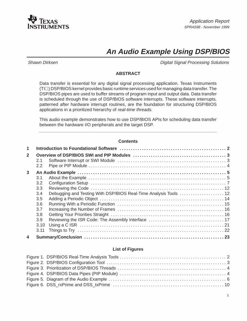
The ability for digital signal processors to handle high-speed arithmetic, I/O and interruptprocessing requires basic scheduling and I/O services. The DSP/BIOS foundation software,included in Code Composer Studio, furnishes a small firmware kernel with basic run-timeservices that software developers can embed on target DSP hardware. DSP/BIOS includesoptimized run-time services such as low-latency threading and scheduling along with a data pipemanagers designed to manage block I/O(also called stream-based or asynchronous I/O). Theembedded DSP/BIOS run-time library and DSP/BIOS plug-ins support a new generation oftesting and diagnostic tools that allows developers and integrators to probe, trace, and monitor aDSP application during its course of execution (see Figure 1. DSP/BIOS Real-Time AnalysisTools) This real-time monitoring lets you view the system running in real-time so that you caneffectively debug and performance-tune your system before deployment.
event state unknownevent runnung
ready to run missed real–time
maximumprocessor
load
statistics accu-mulators
Figure 1. DSP/BIOS Real-Time Analysis Tools
SPRA598
3 An Audio Example Using DSP/BIOS
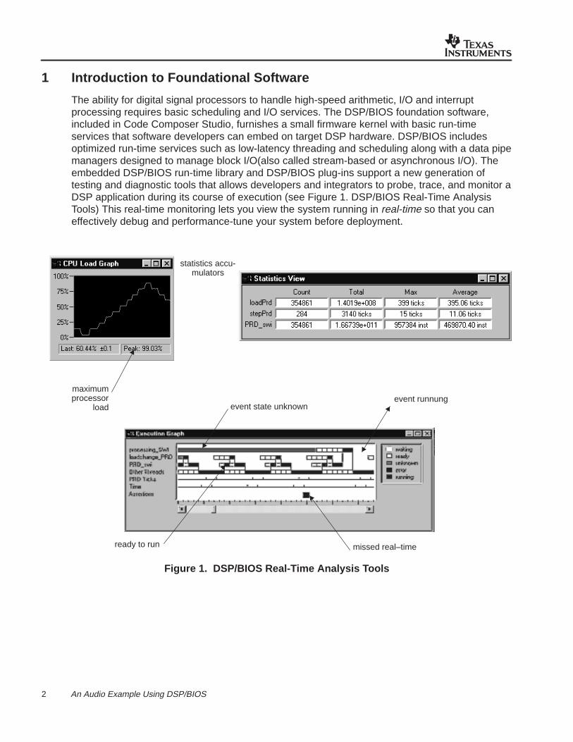
Your target application is designed using the DSP/BIOS Configuration Tool for creating andassigning attributes to individual run-time objects (threads, streams, etc.). Unlike other systemsin which object creation and initialization occur at run-time thought supplementary API calls,incurring further target overhead –especially code space-, all DSP/BIOS objects are staticallyconfigured and bound into an executable program image using hosted tools. In addition tominimizing the target memory footprint by eliminating run-time code and optimizing the layout ofinternal data structures, the static configuration strategy pursued by the DSP/BIOS ConfigurationTool provides the means for early detection of semantic errors through validation of objectattributes prior to program execution.
The DSP/BIOS Configuration Tool serves as a visual editor for creating run-time objects that areused on the target application through the DSP/BIOS APIs. This graphical tool makes it easy fora developer to control a wide range of parameters.
Figure 2. DSP/BIOS Configuration Tool
2 Overview of DSP/BIOS SWI and PIP Modules
The DSP/BIOS kernel is internally organized around a collection of discrete firmware modules,each implementing a coherent subset of the run-time services invoked by the target throughkernel APIs. Individual modules in general will manage one or more instances of a related classof kernel objects and will rely upon global parameter values to control their overall behavior, allof which are statically defined using the DSP/BIOS Configuration Tool.
2.1 Software Interrupt or SWI Module
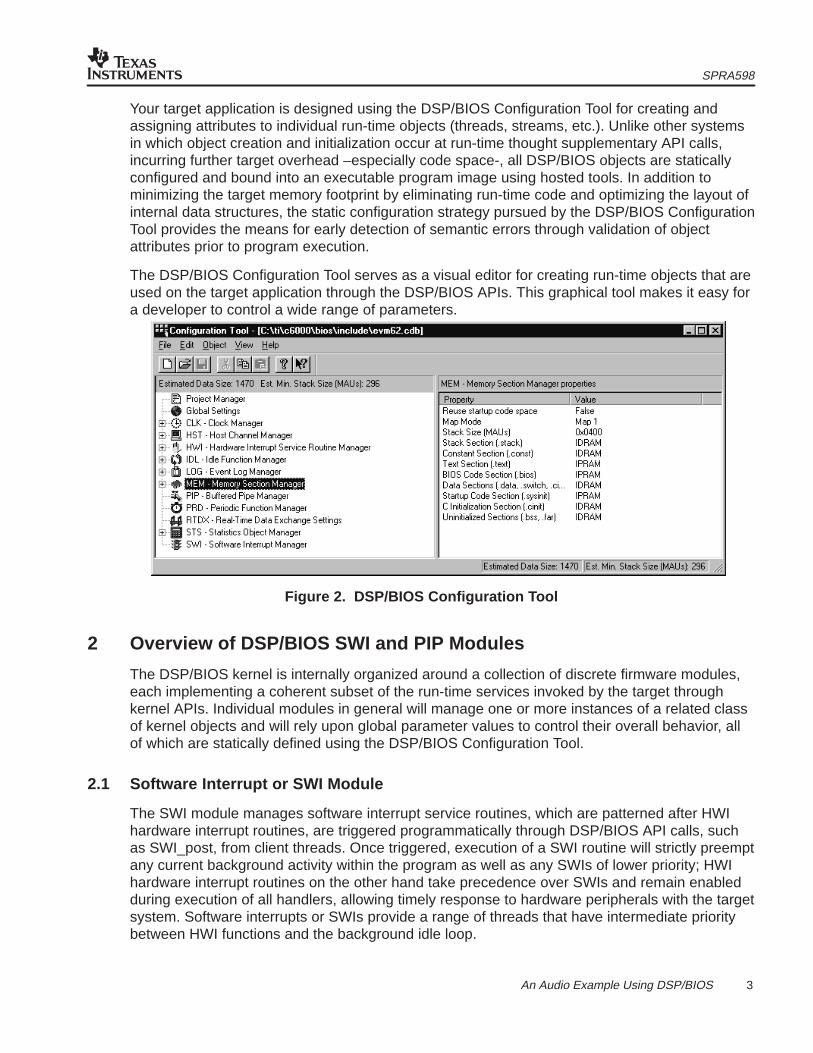
The SWI module manages software interrupt service routines, which are patterned after HWIhardware interrupt routines, are triggered programmatically through DSP/BIOS API calls, suchas SWI_post, from client threads. Once triggered, execution of a SWI routine will strictly preemptany current background activity within the program as well as any SWIs of lower priority; HWIhardware interrupt routines on the other hand take precedence over SWIs and remain enabledduring execution of all handlers, allowing timely response to hardware peripherals with the targetsystem. Software interrupts or SWIs provide a range of threads that have intermediate prioritybetween HWI functions and the background idle loop.
SPRA598
4 An Audio Example Using DSP/BIOS
Time
Prio
rity
Highest
HWI
SWI
SWI
SWI
IDL
Figure 3. Prioritization of DSP/BIOS Threads
2.2 Pipe or PIP Module
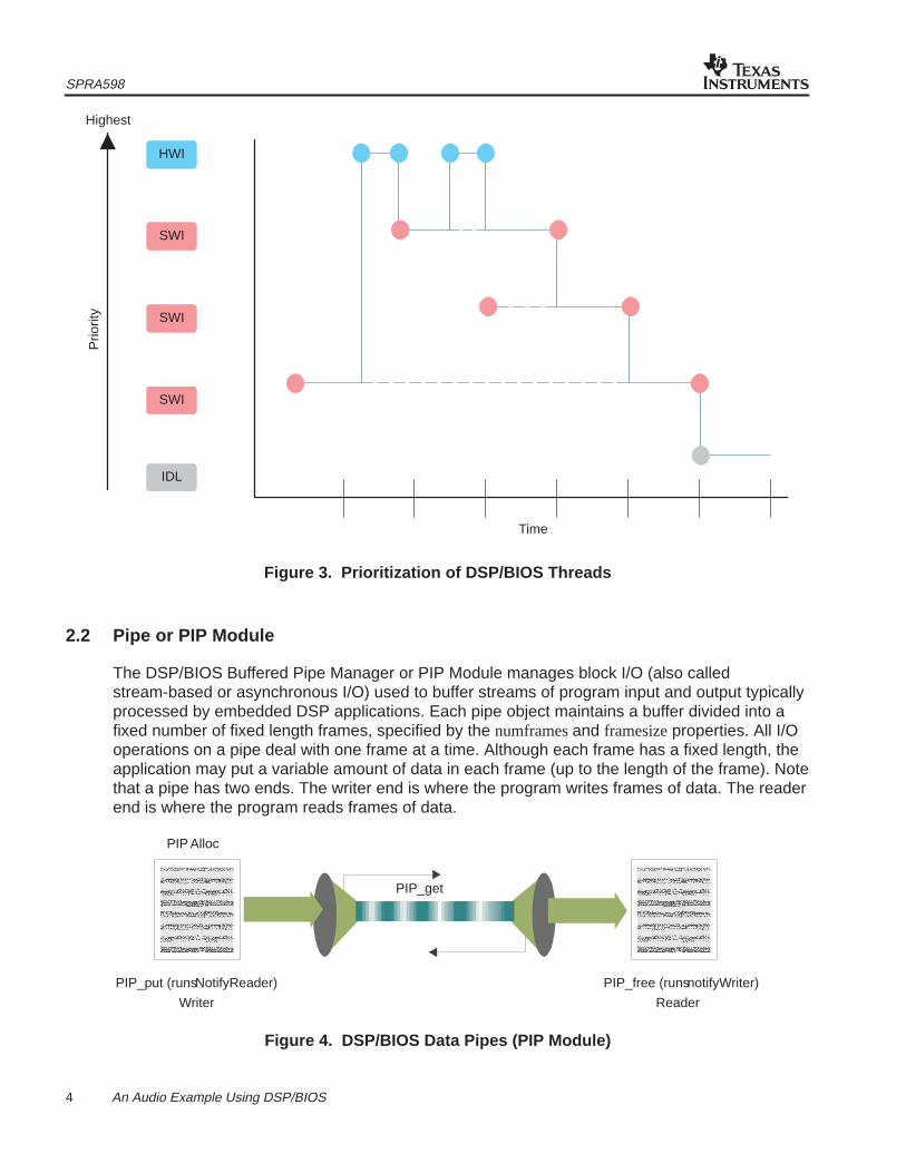
The DSP/BIOS Buffered Pipe Manager or PIP Module manages block I/O (also calledstream-based or asynchronous I/O) used to buffer streams of program input and output typicallyprocessed by embedded DSP applications. Each pipe object maintains a buffer divided into afixed number of fixed length frames, specified by the numframes and framesize properties. All I/Ooperations on a pipe deal with one frame at a time. Although each frame has a fixed length, theapplication may put a variable amount of data in each frame (up to the length of the frame). Notethat a pipe has two ends. The writer end is where the program writes frames of data. The readerend is where the program reads frames of data.
Data notification functions (notifyReader and notifyWriter) are performed to synchronize datatransfer. These functions are triggered when a frame of data is read or written to notify theprogram that a frame is free or data is available. These functions are performed in the context ofthe function that calls PIP_free or PIP_put. They may also be called from the thread that callsPIP_get or PIP_alloc. After PIP_alloc is called, DSP/BIOS checks whether there are more fullframes in the pipe. If so, the notifyReader function is executed. After PIP_alloc is called,DSP/BIOS whether there are more empty frames in the pipe. If so, the notifyWriter function isexecuted.
A pipe should have a single reader and a single writer. Often, one end of a pipe is controlled bya hardware ISR (ex: Serial Port Receiver ISR) and on the other end is controlled by a softwareinterrupt function. Pipes can also be used to transfer data within the program between twoapplication threads.
Next, we use two DSP/BIOS Data Pipes in the audio example to move data between thesoftware interrupt function called audioSWI and a serial port connected to the codec.
3 An Audio Example
This audio example demonstrates how to use DSP/BIOS APIs for scheduling data transferbetween hardware I/O peripherals and the target DSP. This example has been provided to assistwith development for your DSP application program. The following steps will guide you throughthe audio example setup, how to use the DSP/BIOS Configuration Tool and how to use theDSP/BIOS Real-Time Analysis Tools for debugging/testing program code. This example hasbeen installed in both the C5000 or C6000 Code Composer Studio products and can be found inthe ...\ti\c6000\examples\bios\audio or ...\ti\c5400\examples\bios\audio directories.
3.1 About the Example
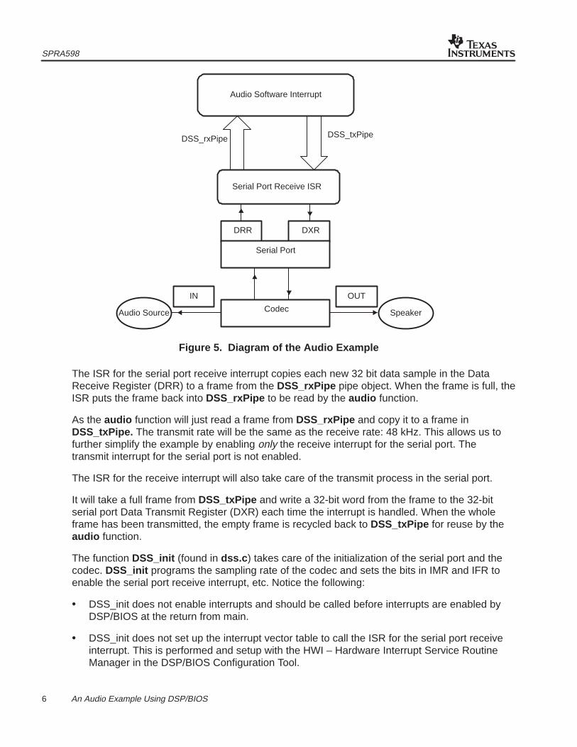
The function audio is written in C and is located in the source code file audio.c found in the...\ti\c6000\examples\bios\audio directory. Two pipe objects are used to exchange databetween the software interrupt and the serial port connected to the codec. These pipes areDSS_rxPipe and DSS_txPipe . Data input from the codec flows from the serial port InterruptService Routine (ISR) through DSS_rxPipe to the software interrupt, where it is copied toDSS_txPipe and sent back to the serial port ISR to be transmitted out through the codec, asshown in Figure 5.
SPRA598
6 An Audio Example Using DSP/BIOS
DSS_rxPipe DSS_txPipe
Audio Software Interrupt
Serial Port Receive ISR
DRR DXR
Serial Port
CodecAudio Source Speaker
IN OUT
Figure 5. Diagram of the Audio Example
The ISR for the serial port receive interrupt copies each new 32 bit data sample in the DataReceive Register (DRR) to a frame from the DSS_rxPipe pipe object. When the frame is full, theISR puts the frame back into DSS_rxPipe to be read by the audio function.
As the audio function will just read a frame from DSS_rxPipe and copy it to a frame inDSS_txPipe. The transmit rate will be the same as the receive rate: 48 kHz. This allows us tofurther simplify the example by enabling only the receive interrupt for the serial port. Thetransmit interrupt for the serial port is not enabled.
The ISR for the receive interrupt will also take care of the transmit process in the serial port.
It will take a full frame from DSS_txPipe and write a 32-bit word from the frame to the 32-bitserial port Data Transmit Register (DXR) each time the interrupt is handled. When the wholeframe has been transmitted, the empty frame is recycled back to DSS_txPipe for reuse by theaudio function.
The function DSS_init (found in dss.c ) takes care of the initialization of the serial port and thecodec. DSS_init programs the sampling rate of the codec and sets the bits in IMR and IFR toenable the serial port receive interrupt, etc. Notice the following:
• DSS_init does not enable interrupts and should be called before interrupts are enabled byDSP/BIOS at the return from main.
• DSS_init does not set up the interrupt vector table to call the ISR for the serial port receiveinterrupt. This is performed and setup with the HWI – Hardware Interrupt Service RoutineManager in the DSP/BIOS Configuration Tool.
SPRA598
7 An Audio Example Using DSP/BIOS
3.2 Configuration Setup
All DSP/BIOS objects are pre-configured and bound into an executable program image. This isdone through the DSP/BIOS Configuration Tool. When you save a configuration file, theConfiguration Tool creates assembly and header files and a linker command file to match yoursettings. These files that are then linked with your code when building your application program.See the sections “Using the Configuration Tool” in the DSP/BIOS User’s Guide and/or “Creatinga Configuration File” in the Code Composer Studio Tutorial for more information.
The following DSP/BIOS objects will be setup/created in this section:
• A software interrupt, audioSWI , to run the audio function.
• Two data pipes, DSS_rxPipe and DSS_txPipe , to exchange data between audioSWI andthe ISR for the serial port receive interrupt.
• Plug in the corresponding ISR for the serial port using the HWI – Hardware Interrupt ServiceRoutine Manager
You begin by opening the project with Code Composer Studio and examining the source codefiles and libraries used in that project.
1. If you installed Code Composer Studio in c:\ti , create a folder called audio in thec:\ti\myprojects folder . (If you installed elsewhere, create a folder within the myprojectsfolder in the location where you installed.)
2. Copy all files from the c:\ti\c6000\examples\bios\audio folder to this new folder.
3. From the Windows Start menu, choose Programs –> Code Composer Studio ‘C6000’ –>Code Composer Studio.
4. Choose Project –> New. Type in audio.mak for the file name in the folder you created andclick Save.
5. Choose File –> New –> DSP/BIOS Configuration.
6. Select the template for your DSP board and click OK.
7. Right-click on the LOG – Event Log Manager and choose the Insert LOG from the pop-upmenu. This creates a LOG object called LOG0.
8. Right-click on the name of the LOG0 object and choose Rename from the pop-up menu.Change the object’s name to trace and change the buffer length property to 256.
9. Right-click on the name of the LOG_system object and choose properties. Change thebuffer length property to 256.
10. Right-click on the SWI – Software Interrupt Manager and choose Insert SWI. Rename thenew SWI0 object audioSWI .
11. Right-click on audioSWI and select Properties from the menu. In the audioSWI propertieswindow, enter _audio for the function , 3 for the mailbox , DSS_rxPipe for arg0 , andDSS_txPipe for arg1 . Click OK to save your changes.
SPRA598
8 An Audio Example Using DSP/BIOS
12. Right-click on the PIP – Buffered Pipe Manager and choose Insert PIP twice. Rename thefirst pipe to DSS_rxPipe and the second pipe to DSS_txPipe .
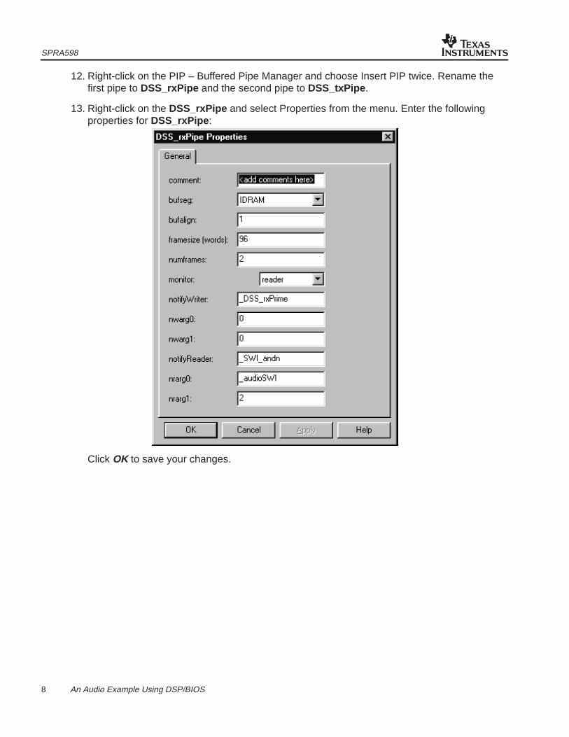
13. Right-click on the DSS_rxPipe and select Properties from the menu. Enter the followingproperties for DSS_rxPipe :
Click OK to save your changes.
SPRA598
9 An Audio Example Using DSP/BIOS
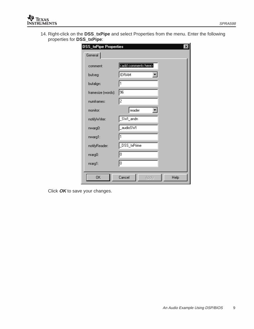
14. Right-click on the DSS_txPipe and select Properties from the menu. Enter the followingproperties for DSS_txPipe :
Click OK to save your changes.
SPRA598
10 An Audio Example Using DSP/BIOS
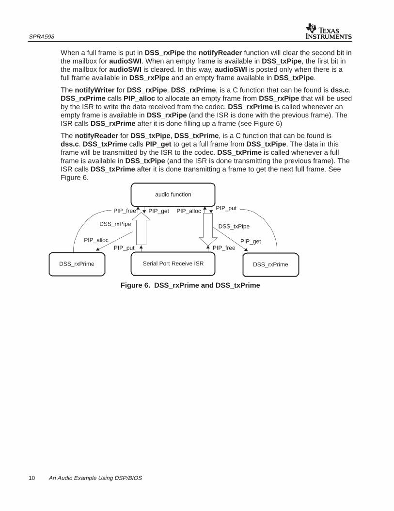
When a full frame is put in DSS_rxPipe the notifyReader function will clear the second bit inthe mailbox for audioSWI . When an empty frame is available in DSS_txPipe , the first bit inthe mailbox for audioSWI is cleared. In this way, audioSWI is posted only when there is afull frame available in DSS_rxPipe and an empty frame available in DSS_txPipe .
The notifyWriter for DSS_rxPipe , DSS_rxPrime , is a C function that can be found is dss.c .DSS_rxPrime calls PIP_alloc to allocate an empty frame from DSS_rxPipe that will be usedby the ISR to write the data received from the codec. DSS_rxPrime is called whenever anempty frame is available in DSS_rxPipe (and the ISR is done with the previous frame). TheISR calls DSS_rxPrime after it is done filling up a frame (see Figure 6)
The notifyReader for DSS_txPipe , DSS_txPrime , is a C function that can be found isdss.c . DSS_txPrime calls PIP_get to get a full frame from DSS_txPipe . The data in thisframe will be transmitted by the ISR to the codec. DSS_txPrime is called whenever a fullframe is available in DSS_txPipe (and the ISR is done transmitting the previous frame). TheISR calls DSS_txPrime after it is done transmitting a frame to get the next full frame. SeeFigure 6.
Serial Port Receive ISR
DSS_rxPipe DSS_txPipe
PIP_put PIP_free
DSS_rxPrime DSS_rxPrime
PIP_free PIP_get PIP_alloc PIP_put
audio function
PIP_alloc PIP_get
Figure 6. DSS_rxPrime and DSS_txPrime
SPRA598
11 An Audio Example Using DSP/BIOS
Now we need to plug in the corresponding ISR for the serial port.
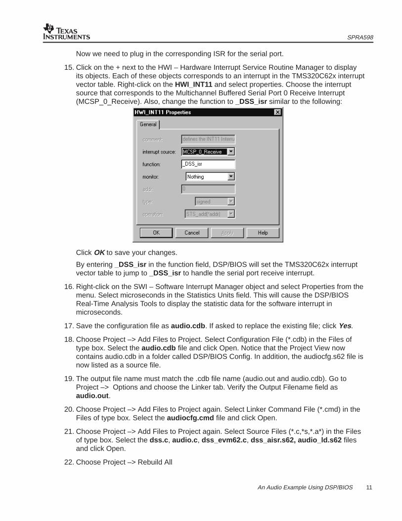
15. Click on the + next to the HWI – Hardware Interrupt Service Routine Manager to displayits objects. Each of these objects corresponds to an interrupt in the TMS320C62x interruptvector table. Right-click on the HWI_INT11 and select properties. Choose the interruptsource that corresponds to the Multichannel Buffered Serial Port 0 Receive Interrupt(MCSP_0_Receive). Also, change the function to _DSS_isr similar to the following:
Click OK to save your changes.
By entering _DSS_isr in the function field, DSP/BIOS will set the TMS320C62x interruptvector table to jump to _DSS_isr to handle the serial port receive interrupt.
16. Right-click on the SWI – Software Interrupt Manager object and select Properties from themenu. Select microseconds in the Statistics Units field. This will cause the DSP/BIOSReal-Time Analysis Tools to display the statistic data for the software interrupt inmicroseconds.
17. Save the configuration file as audio.cdb . If asked to replace the existing file; click Yes.
18. Choose Project –> Add Files to Project. Select Configuration File (*.cdb) in the Files oftype box. Select the audio.cdb file and click Open. Notice that the Project View nowcontains audio.cdb in a folder called DSP/BIOS Config. In addition, the audiocfg.s62 file isnow listed as a source file.
19. The output file name must match the .cdb file name (audio.out and audio.cdb). Go toProject –> Options and choose the Linker tab. Verify the Output Filename field asaudio.out .
20. Choose Project –> Add Files to Project again. Select Linker Command File (*.cmd) in theFiles of type box. Select the audiocfg.cmd file and click Open.
21. Choose Project –> Add Files to Project again. Select Source Files (*.c,*s,*.a*) in the Filesof type box. Select the dss.c , audio.c , dss_evm62.c , dss_aisr.s62, audio_ld.s62 filesand click Open.
22. Choose Project –> Rebuild All
SPRA598
12 An Audio Example Using DSP/BIOS
3.3 Reviewing the Code
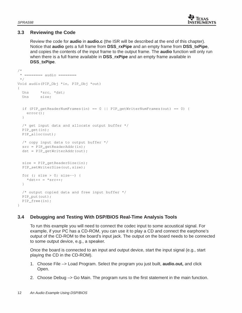
Review the code for audio in audio.c (the ISR will be described at the end of this chapter).Notice that audio gets a full frame from DSS_rxPipe and an empty frame from DSS_txPipe ,and copies the contents of the input frame to the output frame. The audio function will only runwhen there is a full frame available in DSS_rxPipe and an empty frame available inDSS_txPipe .
/* * ======== audio ======== */Void audio(PIP_Obj *in, PIP_Obj *out){ Uns *src, *dst; Uns size;
/* output copied data and free input buffer */ PIP_put(out); PIP_free(in);}
3.4 Debugging and Testing With DSP/BIOS Real-Time Analysis Tools
To run this example you will need to connect the codec input to some acoustical signal. Forexample, if your PC has a CD-ROM, you can use it to play a CD and connect the earphone’soutput of the CD-ROM to the board’s input jack. The output on the board needs to be connectedto some output device, e.g., a speaker.
Once the board is connected to an input and output device, start the input signal (e.g., startplaying the CD in the CD-ROM).
1. Choose File –> Load Program. Select the program you just built, audio.out, and clickOpen.
2. Choose Debug –> Go Main. The program runs to the first statement in the main function.
SPRA598
13 An Audio Example Using DSP/BIOS
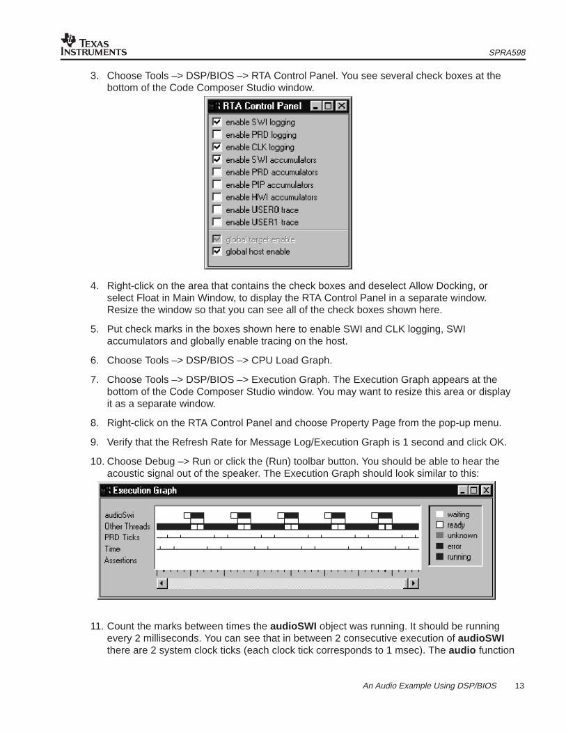
3. Choose Tools –> DSP/BIOS –> RTA Control Panel. You see several check boxes at thebottom of the Code Composer Studio window.
4. Right-click on the area that contains the check boxes and deselect Allow Docking, orselect Float in Main Window, to display the RTA Control Panel in a separate window.Resize the window so that you can see all of the check boxes shown here.
5. Put check marks in the boxes shown here to enable SWI and CLK logging, SWIaccumulators and globally enable tracing on the host.
6. Choose Tools –> DSP/BIOS –> CPU Load Graph.
7. Choose Tools –> DSP/BIOS –> Execution Graph. The Execution Graph appears at thebottom of the Code Composer Studio window. You may want to resize this area or displayit as a separate window.
8. Right-click on the RTA Control Panel and choose Property Page from the pop-up menu.
9. Verify that the Refresh Rate for Message Log/Execution Graph is 1 second and click OK.
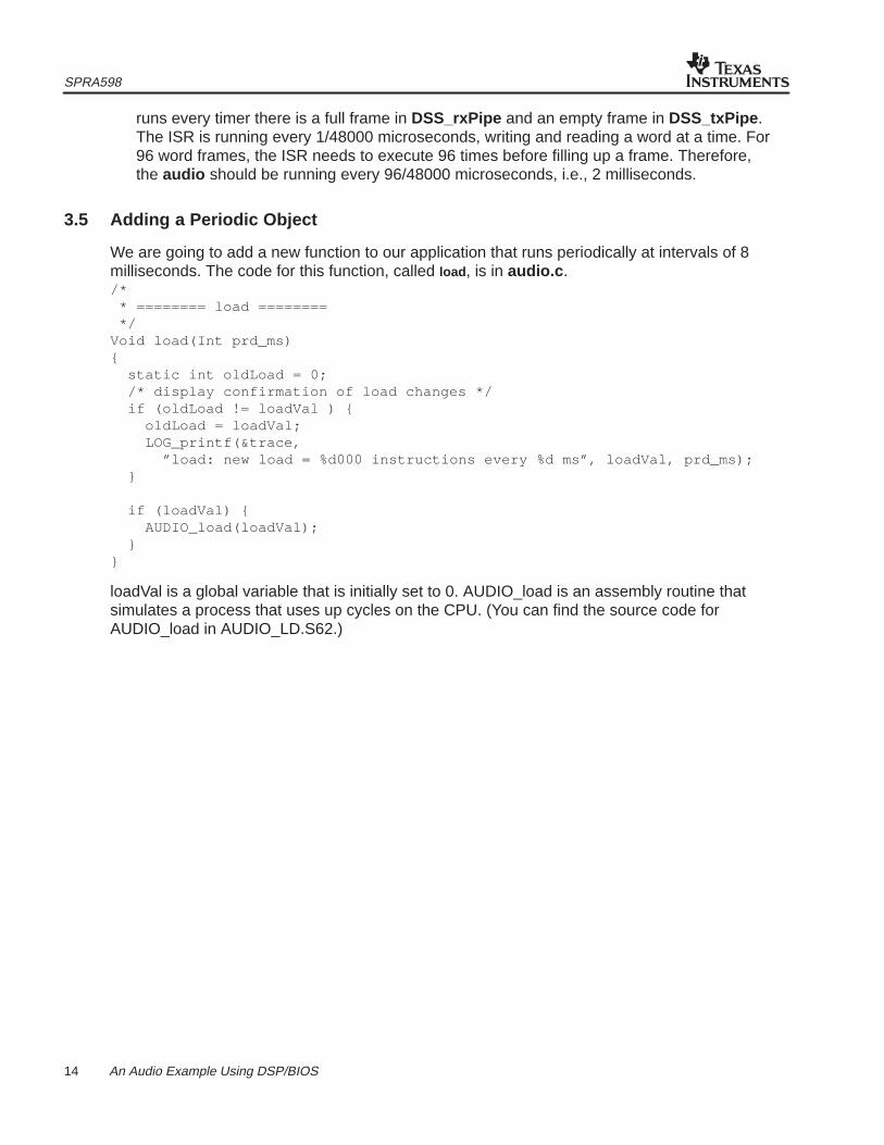
10. Choose Debug –> Run or click the (Run) toolbar button. You should be able to hear theacoustic signal out of the speaker. The Execution Graph should look similar to this:
11. Count the marks between times the audioSWI object was running. It should be runningevery 2 milliseconds. You can see that in between 2 consecutive execution of audioSWIthere are 2 system clock ticks (each clock tick corresponds to 1 msec). The audio function
SPRA598
14 An Audio Example Using DSP/BIOS
runs every timer there is a full frame in DSS_rxPipe and an empty frame in DSS_txPipe .The ISR is running every 1/48000 microseconds, writing and reading a word at a time. For96 word frames, the ISR needs to execute 96 times before filling up a frame. Therefore,the audio should be running every 96/48000 microseconds, i.e., 2 milliseconds.
3.5 Adding a Periodic Object
We are going to add a new function to our application that runs periodically at intervals of 8milliseconds. The code for this function, called load , is in audio.c ./* * ======== load ======== */Void load(Int prd_ms){ static int oldLoad = 0; /* display confirmation of load changes */ if (oldLoad != loadVal ) { oldLoad = loadVal; LOG_printf(&trace, ”load: new load = %d000 instructions every %d ms”, loadVal, prd_ms); } if (loadVal) { AUDIO_load(loadVal); }}
loadVal is a global variable that is initially set to 0. AUDIO_load is an assembly routine thatsimulates a process that uses up cycles on the CPU. (You can find the source code forAUDIO_load in AUDIO_LD.S62.)
SPRA598
15 An Audio Example Using DSP/BIOS
Using the DSP/BIOS Real-Time Analysis Tools you can set how much CPU load load takes upby changing the value of the global variable loadVal .
1. In Code Composer Studio, open audio.cdb . Right-click on the Periodic Function Managerand select Insert PRD from the menu.
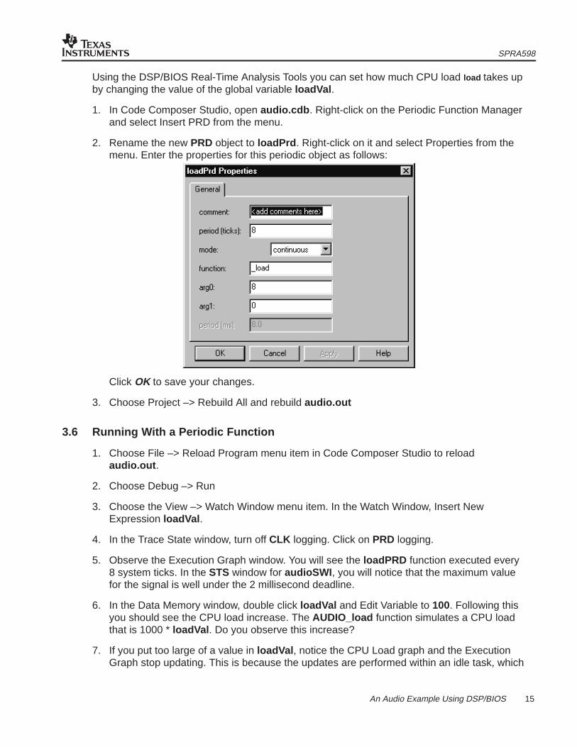
2. Rename the new PRD object to loadPrd . Right-click on it and select Properties from themenu. Enter the properties for this periodic object as follows:
Click OK to save your changes.
3. Choose Project –> Rebuild All and rebuild audio.out
3.6 Running With a Periodic Function
1. Choose File –> Reload Program menu item in Code Composer Studio to reloadaudio.out .
2. Choose Debug –> Run
3. Choose the View –> Watch Window menu item. In the Watch Window, Insert NewExpression loadVal .
4. In the Trace State window, turn off CLK logging. Click on PRD logging.
5. Observe the Execution Graph window. You will see the loadPRD function executed every8 system ticks. In the STS window for audioSWI , you will notice that the maximum valuefor the signal is well under the 2 millisecond deadline.
6. In the Data Memory window, double click loadVal and Edit Variable to 100. Following thisyou should see the CPU load increase. The AUDIO_load function simulates a CPU loadthat is 1000 * loadVal . Do you observe this increase?
7. If you put too large of a value in loadVal , notice the CPU Load graph and the ExecutionGraph stop updating. This is because the updates are performed within an idle task, which
SPRA598
16 An Audio Example Using DSP/BIOS
has the lowest execution priority within the program. Because the higher-priority threadsare using all the processing time, there is not enough time for the host control updates tobe performed. The program is now missing its real-time deadline. Putting a smaller valuein loadVal will continue target/host communication.
8. Observe the STS data for audioSWI . The increase in the load of the periodic functionraised the maximum, but it is still under the real time deadline of 2 milliseconds foraudioSWI .
9. Increase loadVal by entering new values in the Data Memory window. Try 150, 200, etc.Observe the increase on the CPU load and the Max field for the audioSWI STS . Observehow eventually the audioSWI STS maximum reaches more than 2 milliseconds, and theapplication starts to miss real time. You will notice this as you start to hear the quality ofthe acoustic signal output getting worse. Write down the value of loadVal that causes theapplication to start missing real time.
10. In the System Log window, observe how the increase in loadVal lengthened the amountof time it took for loadPRD to execute. (You can see this by counting the number ofsystem ticks that came in while loadPRD was running).
3.7 Increasing the Number of Frames
An increase in the load of loadPRD makes the example miss real time: when loadPRD takestoo long to finish, it makes audioSWI start executing late, since audioSWI has to wait untilloadPRD is done. With only 2 frames, the ISR may finish filling up (or transmitting) one of theframes before audioSWI , delayed by loadPRD , has had a chance to copy the other frame andrelease it back to the pipe. As a result, interrupts will occur before a new frame is available,resulting in a loss of data by the ISR. To address this problem you can increase the number offrames on each pipe, so there is another frame available for the ISR to fill up while audioSWI isdelayed.
1. Open audio.cdb inside Code Composer Studio.
2. Open the Buffered Pipe Manager object, and highlight DSS_rxPipe . Right-click to bring upthe Properties window and change the number of frames in the numframes field to 3.Click OK to save your changes.
3. Repeat the same procedure with DSS_txPipe .
4. Choose Project –> Rebuild All and save the changes.
5. Reload audio.out and choose Debug –> Run.
6. Choose View –> Memory window, enter the value for loadVal that you had previouslywritten down. Does the quality of sound deteriorate?
7. Observe the STS window for audioSig . Is the Maximum under 2 msec? Is audioSWImeeting its deadline?
8. Keep increasing loadVal . The application will eventually run into the same problem asbefore, and audioSWI will start missing real time again.
3.8 Getting Your Priorities Straight
Adding a new buffer seemed to solve the situation until loadVal became too large, and theapplication started to miss real time again. Why did this happen?
SPRA598
17 An Audio Example Using DSP/BIOS
When audioSWI was posted, it did not run immediately but had to wait until loadPRD finished.When loadPRD started to take more than 2 milliseconds to execute, it caused the audioSWIwaiting for it to be late for its 2 milliseconds deadline. When we added a new buffer, weincreased the amount of time that audioSWI could be late, as there was an extra buffer that theISR could continue to fill. However, this kind of arrangement will not help us indefinitely. IfloadVal becomes large enough, eventually audioSWI will be delayed long enough that the ISRwill run out of available frames.
To solve this situation we need audioSWI to be able to preempt the periodic software interrupt(PRD_swi ) that calls loadPRD . If audioSWI can preempt PRD_swi , audioSWI will runwhenever it is posted, regardless of whether loadPRD is finished, because it will take away thecontrol of the CPU (preempt) from the periodic function. Since audioSWI is no longer delayedby loadPRD , the load of loadPRD will no longer make our application miss real time.
1. Open audio.cdb inside Code Composer Studio. Click on the Software Interrupt Managerobject to highlight it.
2. On the right pane, drag audioSWI above PRD_swi . audioSWI becomes the highestpriority software interrupt.
3. Choose Project –> Rebuild All and save the changes.
Follow the same steps as in the previous section and observe how audioSWI does not miss realtime when loadVal is increased. Note in the Message Log window how audioSWI preemptsloadPRD . Note in the STS window for audioSWI how the maximum remains constantregardless of changes to loadVal .
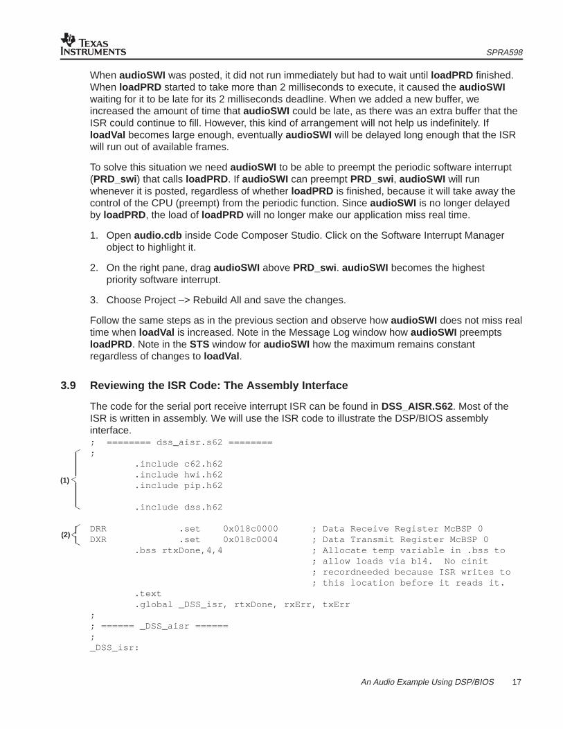
3.9 Reviewing the ISR Code: The Assembly Interface
The code for the serial port receive interrupt ISR can be found in DSS_AISR.S62. Most of theISR is written in assembly. We will use the ISR code to illustrate the DSP/BIOS assemblyinterface.; ======== dss_aisr.s62 ========; .include c62.h62 .include hwi.h62 .include pip.h62
.include dss.h62
DRR .set 0x018c0000 ; Data Receive Register McBSP 0DXR .set 0x018c0004 ; Data Transmit Register McBSP 0 .bss rtxDone,4,4 ; Allocate temp variable in .bss to ; allow loads via b14. No cinit ; recordneeded because ISR writes to ; this location before it reads it. .text .global _DSS_isr, rtxDone, rxErr, txErr;; ====== _DSS_aisr ======;_DSS_isr:
(1)
(2)
SPRA598
18 An Audio Example Using DSP/BIOS
stw a0,*b15––[2] ; push temp registers stw a1,*b15––[2] stw a2,*b15––[2] stw b1,*b15––[2] stw b2,*b15––[2] ; rxDone = 0, txDone = 0 zero a2 ; if (DSS_rxCnt) { ldw *+b14(_DSS_rxCnt),b1 nop 4 [!b1] b rxErr ; process rx error ; *DSS_rxPtr++ = *DRR; [b1] mvkl DRR,a1 ; load address of serial port DRR [b1] mvkh DRR,a1 [b1] ldw *a1,a1 ; read word from DRR ||[b1] ldw *+b14(_DSS_rxPtr),b1 ; load DSS_rxPtr [b1] ldw *+b14(_DSS_rxCnt),b2 ; load DSS_rxCnt nop 3 stw a1,*b1++ ; store DRR at *DSS_rxPtr, auto ; increment DSS_rxPtr stw b1,*+b14(_DSS_rxPtr) ; store updated DSS_rxPtr ; DSS_rxCnt––; sub b2,1,b2 ; decrement DSS_rxCnt stw b2,*+b14(_DSS_rxCnt) ; store updated DSS_rxCnt ; if (DSS_rxCnt == 0) { ; rxDone = 1; ; } ; } [!b2] mvk 1,a2checkTx: ; if (DSS_txCnt) {
ldw *+b14(_DSS_txCnt),b1 nop 4 [!b1] b txErr ; process tx error ; *DXR = *DSS_txPtr++; [b1] ldw *+b14(_DSS_txPtr),b1 ; load DSS_txPtr [b1] ldw *+b14(_DSS_txCnt),b2 ; load DSS_txCnt nop 3 ldw *b1++,a0 ; load word pointed to by DSS_txPtr ; autoincrement DSS_txPtr stw b1,*+b14(_DSS_txPtr) ; store updated DSS_txPtr mvkl DXR,a1 ; load address of serial port DXR mvkh DXR,a1 ; DSS_txCnt––; sub b2,1,b2 ; decrement DSS_txCnt stw a0,*a1 ; write word to DXR stw b2,*+b14(_DSS_txCnt) ; store updated DSS_txCnt ; if (DSS_txCnt == 0) { ; txDone = 1; ; } ; } [!b2] or 2,a2,a2
(3)
(4)
(5)
SPRA598
19 An Audio Example Using DSP/BIOS
checkDn: ;if ((rxDone | txDone) == 0) { [a2] b Done ; if rxDone or txDone do Done processing stw a2,*+b14(rtxDone) ; store done flags into memory ; return; /* return from interrupt */ ; } [!a2] ldw *++b15[2],b2 ; restore temp registers [!a2] ldw *++b15[2],b1 [!a2] ldw *++b15[2],a2 [!a2] ldw *++b15[2],a1 b irp ; return from interrupt ldw *++b15[2],a0 nop 4Done: ldw *++b15[2],b2 ; restore temp registers ldw *++b15[2],b1 ldw *++b15[2],a2 ldw *++b15[2],a1 ldw *++b15[2],a0 nop 4 HWI_enter C62_ABTEMPS, 0, 0xffff, 0 ; if (rxDone) { ldw *+b14(rtxDone),b0 ; load done flags from memory nop 4 and b0,1,b0 ; check if rxDone set [!b0] b txDone nop 3 ; PIP_put(&DSS_rxPipe); [b0] mvkl _DSS_rxPipe,a4 ; load pipe address [b0] mvkh _DSS_rxPipe,a4 PIP_put ; DSS_rxPrime(); ; } b _DSS_rxPrime mvkl txDone,b3 ; set return pointer to come back here mvkh txDone,b3 nop 3txDone: ; if (txDone) { ldw *+b14(rtxDone),b0 ; load done flags from memory nop 4 and b0,2,b0 ; check if txDone set [!b0] b allDone nop 3 ; PIP_free(&DSS_txPipe); [b0] mvkl _DSS_txPipe,a4 ; load pipe address [b0] mvkh _DSS_txPipe,a4 PIP_free ; DSS_txPrime(); ; } b _DSS_txPrime mvkl allDone,b3 ; set return pointer to come back here
(6)
(7)
(8)
(9)
SPRA598
20 An Audio Example Using DSP/BIOS
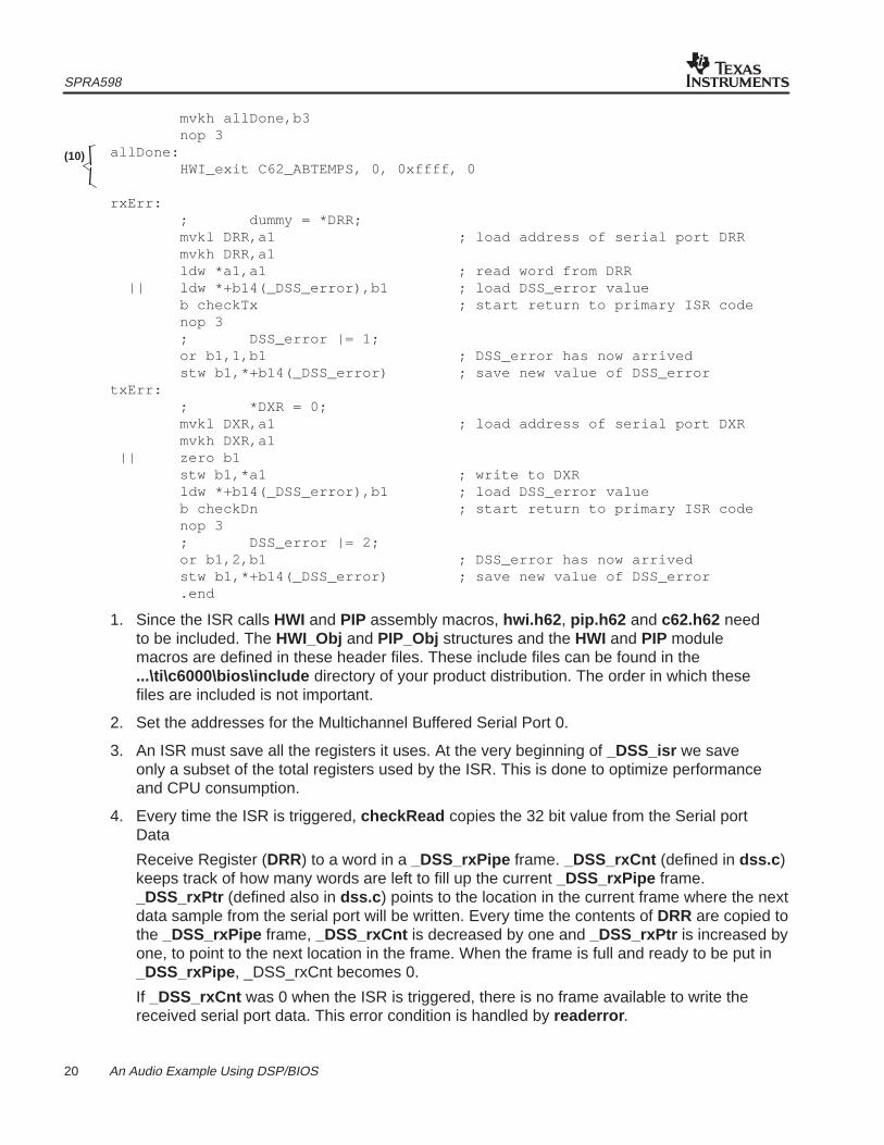
mvkh allDone,b3 nop 3allDone: HWI_exit C62_ABTEMPS, 0, 0xffff, 0 rxErr: ; dummy = *DRR; mvkl DRR,a1 ; load address of serial port DRR mvkh DRR,a1 ldw *a1,a1 ; read word from DRR || ldw *+b14(_DSS_error),b1 ; load DSS_error value b checkTx ; start return to primary ISR code nop 3 ; DSS_error |= 1; or b1,1,b1 ; DSS_error has now arrived stw b1,*+b14(_DSS_error) ; save new value of DSS_errortxErr: ; *DXR = 0; mvkl DXR,a1 ; load address of serial port DXR mvkh DXR,a1 || zero b1 stw b1,*a1 ; write to DXR ldw *+b14(_DSS_error),b1 ; load DSS_error value b checkDn ; start return to primary ISR code nop 3 ; DSS_error |= 2; or b1,2,b1 ; DSS_error has now arrived stw b1,*+b14(_DSS_error) ; save new value of DSS_error .end
1. Since the ISR calls HWI and PIP assembly macros, hwi.h62 , pip.h62 and c62.h62 needto be included. The HWI_Obj and PIP_Obj structures and the HWI and PIP modulemacros are defined in these header files. These include files can be found in the...\ti\c6000\bios\include directory of your product distribution. The order in which thesefiles are included is not important.
2. Set the addresses for the Multichannel Buffered Serial Port 0.
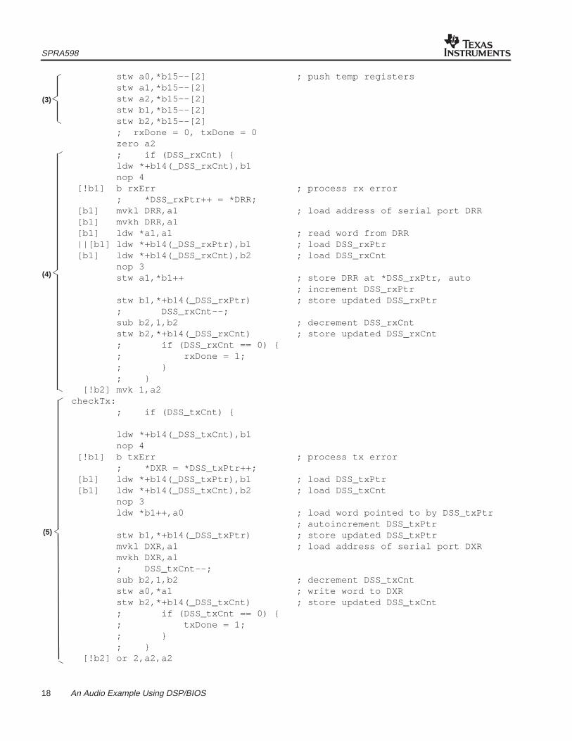
3. An ISR must save all the registers it uses. At the very beginning of _DSS_isr we saveonly a subset of the total registers used by the ISR. This is done to optimize performanceand CPU consumption.
4. Every time the ISR is triggered, checkRead copies the 32 bit value from the Serial portData
Receive Register (DRR) to a word in a _DSS_rxPipe frame. _DSS_rxCnt (defined in dss.c )keeps track of how many words are left to fill up the current _DSS_rxPipe frame._DSS_rxPtr (defined also in dss.c ) points to the location in the current frame where the nextdata sample from the serial port will be written. Every time the contents of DRR are copied tothe _DSS_rxPipe frame, _DSS_rxCnt is decreased by one and _DSS_rxPtr is increased byone, to point to the next location in the frame. When the frame is full and ready to be put in_DSS_rxPipe , _DSS_rxCnt becomes 0.
If _DSS_rxCnt was 0 when the ISR is triggered, there is no frame available to write thereceived serial port data. This error condition is handled by readerror .
(10)
SPRA598
21 An Audio Example Using DSP/BIOS
5. Every time the ISR is triggered, checkWrite copies a word from a _DSS_txPipe to the 32bit Serial port DataTransmit Register (DXR). _DSS_txCnt (defined in dss.c ) keeps trackof how many words are left to be transmitted in the current frame. _DSS_txPtr (definedalso in dss.c ) points the location in the frame from where the next data sample will becopied to DXR. Every time a data sample is copied to DXR,
_DSS_txCnt is decreased by one and _DSS_txPtr is increased by one, to point to the nextlocation in the frame. When all the data in the frame has been transmitted, and the frame isready to be recycled back to _DSS_txPipe, _DSS_txCnt becomes 0.
If _DSS_txCnt was 0 when the ISR is triggered, there is no full frame available to write datato the serial port data transmit register. This error condition is handled by writeError .
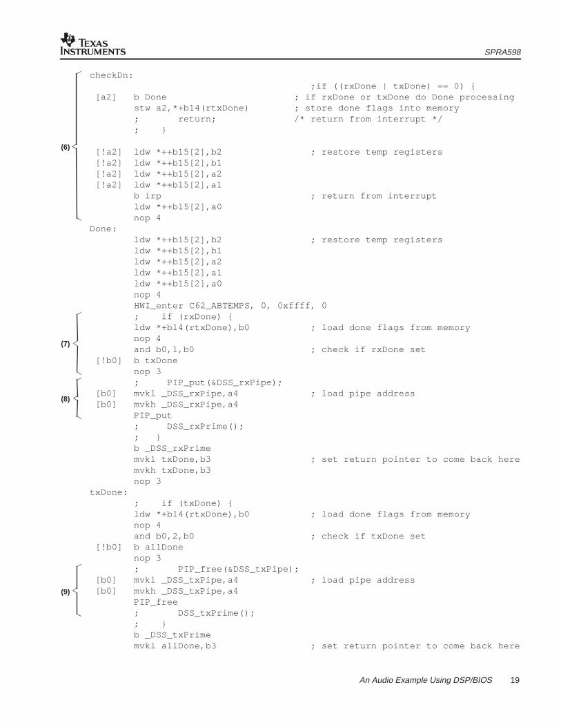
6. Check whether the last received data sample filled up a _DSS_rxPipe frame or whetherthe last transmitted data sample emptied a _DSS_txPipe . If neither of these conditions ismet, we restore the registers and return from the ISR.
7. If a _DSS_rxPipe frame is full, the ISR needs to call the PIP_put assembly macro to putthe frame back to the pipe. Calling PIP_put may result in the audio function being posted.The ISR will also call the C function _DSS_rxPrime to allocate the next empty frame from_DSS_rxPipe (if available). In order to do this the ISR needs to:
• Save any registers that may be used by DSP/BIOS internally (since kernel macros will becalled).
• Save any registers that may be used by the compiler for the C function.
• Disable the scheduler, so that if a software signal is triggered as a result of a call to a kernelmacro, the signal does not start executing in the context of the ISR. Instead, the ISR shouldfinish first and then re-enable the scheduler so that the software signal can be executed.
To meet these requirements the ISR calls HWI_enter C62_ABTEMPS, 0, 0xffff, 0 .HWI_enter is an assembly macro that disables the scheduler and saves all the registersspecified by the masks
8. We need to meet the preconditions before calling PIP_put : a4 should contain the addressof the pipe object (_DSS_rxPipe ). There are no postconditions for PIP_put .
9. As with PIP_put , we need to meet PIP_free preconditions by loading the pipe objectaddress into a4. PIP_free does not have any postconditions.
10. At the end of the ISR HWI_exit is called to restore registers, re-enable the scheduler, andexit the ISR
3.10 Using a C ISR
1. In the ...\ti\c6000\examples\bios\audio directory you will find a C version of the ISR inthe file dss_cisr.c . To use the C version of the ISR, remove the DSS_AISR.S62 file fromthe project and add the DSS_CISR.C and DSS_ASM.S62 files.
2. Save the changes and rebuild audio.out.
3. Load audio.out . Run the application. Note how using the C ISR increases the CPU loadover the assembly version of the ISR.
SPRA598
22 An Audio Example Using DSP/BIOS
To use DSS_cisr as our ISR we need to write a small stub function in assembly that calls thisDSS_cisr . This assembly function is named _DSS_isr , as this is the function name entered inthe HWI_INT11 object (therefore, the function that is plugged in the TMS320C62x interruptvector table). The code for this function can be found in DSS_ASM.S62:; ======== dss_asm.s62 ========;; .include c62.h62 .include hwi.h62 .global _DSS_isr .global _DSS_cisr .text;; ======== _DSS_isr ========;; Calls the C ISR code;_DSS_isr: HWI_enter C62_ABTEMPS, 0, 0xffff, 0 b _DSS_cisr mvkl dssi,b3 mvkh dssi,b3 nop 3dssi: HWI_exit C62_ABTEMPS, 0, 0xffff, 0 .end
_DSS_isr needs to save all the registers that it uses. Therefore, it needs to use theHWI_enter/HWI_exit macros to preserve all those registers that are not saved by the compiler. It alsoneeds to make sure that the scheduler is disabled, as DSS_cisr will call DSP/BIOS APIs that may post asoftware interrupt.
3.11 Things to Try
• Increase the size of the frames in the pipes. Observe the System Log and note any changeson the frequency at which the signal runs. What happens when we double the frame size?
• Change the frame size in the pipes to 512 words. Observe the changes in the CPU load.Observe the System Log. When you increase the buffer size to 8 times the original value, thePIP operations (PIP_alloc , PIP_put , PIP_get , PIP_free ), and the posting of the audiofunction occur at a frequency that is 8 times smaller. (You can check this by looking at theSystem Log). However, this does not cause an equivalent reduction on the CPU load. This isan indication that the PIP operations and the software interrupt scheduler have a smalloverhead in the overall CPU load for this application. Servicing the ISR and copying the dataremain the largest overhead on the CPU.
• Enable the monitors on the signal side of the pipes. Observe the frequency at which framesflow in and out of the pipes, and how it changes with frame size. Note the impact of themonitors on the CPU.
• Enable a monitor for HWI_INT11 and observe its impact on the CPU. In general, you canobserve how enabling instrumentation (logging, accumulators, monitors) in the applicationimpacts the CPU load. Notice if there is a dependency with the frame size of the pipes.
SPRA598
23 An Audio Example Using DSP/BIOS
4 Summary/Conclusion
This audio example has demonstrated how to configure and use DSP/BIOS APIs for schedulingdata transfer between the hardware I/O peripherals and the target DSP. This example has beenprovided to assist with your DSP application development and the understanding DSP/BIOS.
IMPORTANT NOTICE
Texas Instruments and its subsidiaries (TI) reserve the right to make changes to their products or to discontinueany product or service without notice, and advise customers to obtain the latest version of relevant informationto verify, before placing orders, that information being relied on is current and complete. All products are soldsubject to the terms and conditions of sale supplied at the time of order acknowledgement, including thosepertaining to warranty, patent infringement, and limitation of liability.
TI warrants performance of its semiconductor products to the specifications applicable at the time of sale inaccordance with TI’s standard warranty. Testing and other quality control techniques are utilized to the extentTI deems necessary to support this warranty. Specific testing of all parameters of each device is not necessarilyperformed, except those mandated by government requirements.
CERTAIN APPLICATIONS USING SEMICONDUCTOR PRODUCTS MAY INVOLVE POTENTIAL RISKS OFDEATH, PERSONAL INJURY, OR SEVERE PROPERTY OR ENVIRONMENTAL DAMAGE (“CRITICALAPPLICATIONS”). TI SEMICONDUCTOR PRODUCTS ARE NOT DESIGNED, AUTHORIZED, ORWARRANTED TO BE SUITABLE FOR USE IN LIFE-SUPPORT DEVICES OR SYSTEMS OR OTHERCRITICAL APPLICATIONS. INCLUSION OF TI PRODUCTS IN SUCH APPLICATIONS IS UNDERSTOOD TOBE FULLY AT THE CUSTOMER’S RISK.
In order to minimize risks associated with the customer’s applications, adequate design and operatingsafeguards must be provided by the customer to minimize inherent or procedural hazards.
TI assumes no liability for applications assistance or customer product design. TI does not warrant or representthat any license, either express or implied, is granted under any patent right, copyright, mask work right, or otherintellectual property right of TI covering or relating to any combination, machine, or process in which suchsemiconductor products or services might be or are used. TI’s publication of information regarding any thirdparty’s products or services does not constitute TI’s approval, warranty or endorsement thereof.