Journal of Intelligent Manufacturing (1994) 5, 235-249 An automated coding and classification system with supporting database for effective design of manufacturing systems MUNISH AGARWAL 1, ALl K. KAMRANI 2 and HAMID R. PARSAEI 3 :Department of Engineering Management, University of Missouri-Rolla, Rolla, MO 65401, USA 2Department of lndustrial and Manufacturing Systems Engineering, The University of Michigan-Dearborn, Dearborn, MI 48128, USA 3Industrial Engineering Department, University of Louisville, Louisville KY 40292, USA The philosophy of group technology (GT) is an important concept in the design of flexible manufacturing systems and manufacturing cells. Group technology is a manufacturing philosophy that identifies similar parts and groups them into families. Beside assigning unique codes to these parts, group technology developers intend to take advantage of part similarities during design and manufacturing processes. GT is not the answer to all manufacturing problems, but it is a good management technique with which to standardize efforts and eliminate duplication. Group technology classifies parts by assigning them to different families based on their similarities in: (1) design attributes (physical shape and size), and/or (2) manufacturing attributes (processing sequence). The manufacturing industry today is process focused; departments and sub units are no longer independent but are interdependent. If the product development process is to be optimized, engineering and manufacturing cannot remain independent any more: they must be coordinated. Each sub-system is a critical component within an integrated manufacturing framework. The coding and classification system is the basis of CAPP and the functioning and reliability of CAPP depends on the robustness of the coding system. The proposed coding system is considered superior to the previously proposed coding systems, in that it has the capability to migrate into multiple manufacturing environments. This article presents the design of a coding and classification system and the supporting database for manufacturing processes based on both design and manufacturing attributes of parts. An interface with the spreadsheet will calculate the machine operation costs for various processes. This menu-driven interactive package is implemented using dBASE-IV. Part Family formation is achieved using a KAMCELL package developed in TURBO Pascal. Keywords: Group technology, automated coding 1. Introduction 1.1. Group technology philosophy Group technology is the realization that many problems are similar, and therefore by grouping similar problems, a single solution can be found (Chang et al., 1991). 0956-5515 O 1994 Chapman & Hall Group technology is generally considered as a manufac- turing philosophy which identifies and exploits the same- ness or similarity of parts and operation processes in the design and manufacture of products. More and more manufacturing industries involved with small to medium lot size and a variety of products are becoming interested
Transcript
Journal o f Intelligent Manufacturing (1994) 5, 235-249
An automated coding and classification system with supporting database for effective design of manufacturing systems
M U N I S H A G A R W A L 1, A L l K. K A M R A N I 2 and H A M I D R. P A R S A E I 3
:Department of Engineering Management, University of Missouri-Rolla, Rolla, MO 65401, USA 2Department of lndustrial and Manufacturing Systems Engineering, The University of Michigan-Dearborn, Dearborn, MI 48128, USA 3Industrial Engineering Department, University of Louisville, Louisville KY 40292, USA
The philosophy of group technology (GT) is an important concept in the design of flexible manufacturing systems and manufacturing cells. Group technology is a manufacturing philosophy that identifies similar parts and groups them into families. Beside assigning unique codes to these parts, group technology developers intend to take advantage of part similarities during design and manufacturing processes. GT is not the answer to all manufacturing problems, but it is a good management technique with which to standardize efforts and eliminate duplication. Group technology classifies parts by assigning them to different families based on their similarities in: (1) design attributes (physical shape and size), and/or (2) manufacturing attributes (processing sequence). The manufacturing industry today is process focused; departments and sub units are no longer independent but are interdependent. If the product development process is to be optimized, engineering and manufacturing cannot remain independent any more: they must be coordinated. Each sub-system is a critical component within an integrated manufacturing framework. The coding and classification system is the basis of CAPP and the functioning and reliability of CAPP depends on the robustness of the coding system. The proposed coding system is considered superior to the previously proposed coding systems, in that it has the capability to migrate into multiple manufacturing environments. This article presents the design of a coding and classification system and the supporting database for manufacturing processes based on both design and manufacturing attributes of parts. An interface with the spreadsheet will calculate the machine operation costs for various processes. This menu-driven interactive package is implemented using dBASE-IV. Part Family formation is achieved using a KAMCELL package developed in TURBO Pascal.
Keywords: Group technology, automated coding
1. Introduction
1.1. Group technology philosophy
Group technology is the realization that many problems are similar, and therefore by grouping similar problems, a single solution can be found (Chang et al., 1991).
0956-5515 O 1994 Chapman & Hall
Group technology is generally considered as a manufac- turing philosophy which identifies and exploits the same- ness or similarity of parts and operat ion processes in the design and manufacture of products. More and more manufacturing industries involved with small to medium lot size and a variety of products are becoming interested
236 Agarwul et al.
in this concept. It has also been recognized that GT is an essential element of the foundation for the successful development and implementation of computer aided manufacturing, through the application of the part family formation and analysis.
In batch-type manufacturing, traditionally, each part is treated as unique in design, process planning, production control and tooling. However, by grouping similar parts based on geometrical shapes or operation processes, and forming machine groups or cells for part family produc- tion, process planning simplification, improvement and production control enhancement is achieved. Group
manufacturing activities has been studied and practiced for some time. For product design, it is evident that components having similar shapes are grouped into design families and a new design can be created by modifying the existing composite design of the part family. In the case of manufacturing applications, parts which are grouped into one family may not possess a similar shape, but may require similar manufacturing processes. This would result in the design of a work cell, and parts requiring similar manufacturing operations are assigned and produced in this cell.
technology application also reduces the programming required by each cell. The workpieces moving through 1.2. Part family formation and machine grouping
the cell have similar operations or the same route in the Grouping parts into families is a tedious task which work cell, and therefore would lead to the more effective requires careful planning and consideration. Basic utilization of expensive NC machines and machine cen- methods which are available for solving the GT problems ters. in manufacturing can be classified into: (1) classification;
To achieve higher productivity from design to manu- (2) production-flow analysis; and (3) cluster analysis. facture, many manufacturing industries have become increasingly interested in the implementation of GT. These companies apply their principles in their own way, although in some cases it is not identified as GT, but is
2. Classification
considered simply as a good managerial and operational practice. It is no longer restricted only to cellular manufacturing (CM) or computer aided process planning (CAPP), but is also used as a part of the total system design for overall company operation. It is evident that the new technologies, such as industrial robots, CNC, DNC, and machining centers, require more computer- integrated capabilities. This, in turn, requires the ap- plication of GT in this manufacturing environment. A part classification system, which is considered as an essential part of the grouping task, can be evolved as a means of describing parts which can be readily integrated with the database. The evolution of computer integrated production systems has led to generative design and process planning.
The application of group technology in the optimiza- tion of the process planning task and the control of the
Classification is defined as a process of grouping parts into families based on some set of rules and principles. This approach can be further categorized into the visual method (ocular) and coding procedure. Grouping done based on the ocular method is a process of identifying part families by visually inspecting parts and assigning them to families and the production cells to which they belong. This approach is limited to parts with large physical geometries and it is not an optimal approach since it lacks accuracy and sophistication. This approach becomes inefficient as the number of parts increases.
The coding method of grouping is considered to be the most powerful and reliable. In this method, each part is inspected individually by means of its design and proces- sing features. Coding can be defined as a process of tagging parts with a set of symbols which will reflect the part’s characteristics. A well-designed classification and coding system may result in several benefits for the manufacturing plant. A part’s code can consist of a
0 0ww.l Jk.C. numerical, alphabetical or alphanumerical string. Three
/\ types of coding systems exist. These are:
NO”-t0t.tlO”*I 0 0 ROt.ll0ll.l (1) Hierarchical (monocode) structure: in this method, each character (code) is a further expansion of the
St.ce.d 10 both .“d. 0’ ‘0 st.pp.li to on. .“d previous character. This indicates that the meaning of the code is dependent on the meaning of the previous
DCLASS by BYU, A S-Digit Code character in the code’s string. The advantage of this
/11/uuu/li approach is the amount of information which the code
Basic Shape Form
can represent in a relatively small number of digits. Shapa Size Precision Material However, a coding system based on this structure is
complicated and very difficult to implement. Figure 1 Fig. 1. Sample structure of hierarchical code. illustrates the general structure of this method of coding.
An automated coding and classification system for effective design 237
Digit Feature
1 External
2 Internal
M[CLASS by TNO (1976), A 12-Digits Code
I I l i--1 I-- Main Shape Position Main Dim. Shape Elements of S.E. Dimension Ratio
1 2
Cylindrical Box
None Center Hole
AUX. Tolerance Material D im. Codes Codes
Fig. 2. A sample structure of chain code.
An example of this form of coding structure is DCLASS developed at Brigham Young University (BYU) (Chang et al., 1991; Amirouche, 1993), in which an 8-digit code can be constructed based on the design attributes of parts.
(2) Chain (attribute, or polycode) structure: in this structure, the meaning of each character (code) is independent of any other character within the code string. In this approach, each attribute of a part is tagged with a specific position in the code. This structure is simple to implement, but a large number of digits may be required to represent characteristics of a part. Figure 2 illustrates the general layout of a code implemented based on this structure. An example of this coding structure is MICLASS which was developed by TNO (Houtzeel and Schilperoort, 1976) of Holland. This is a 12-digit coding system based on the design attributes of parts.
(3) Hybrid: most of the coding systems available are implemented using this type of structure. A hybrid coding system is a combination of both monocode and polycode structures, taking advantage of the characteris- tics of the two previously described structures. Figure 3 illustrates the general structure of this coding approach. Examples of this coding structure are the OPITZ coding system developed in Germany during the 1960s (OPITZ, 1970) and KAMKODE (Kamrani, 1991).
OPITZ by H. Opitz (1970), A 13-Digits Code
I I I I I I r l I I I I I I I I Form Codes Supplementary Secondary
Codes Codes
Fig. 3. A sample structure of hybrid code.
3. Production flow analysis (PFA)
This method relies on route sheets developed by the process planner, and the grouping is done based on the sequence of operations. This method was developed by Professor J. L. Burbidge (Snead, 1990), and it is im- plemented in four hierarchical design steps and analyses. These are:
(1) Factory flow analysis: in this stage, the material flow between the different production processes in the factory is studied, and machines that are capable of producing and completing all the parts in the major part families without any visit to other intermediate families are grouped together (intercellular material handling). This will assure the production of the part families without requiring operations in other departments or machine groups.
(2) Group analysis: in this stage, the major part families and the machine groups are subdivided into smaller families, still maintaining the required machining within the group machines, not requiring any visit to other machine groups and eliminating possible intercellu- lar material handling.
(3) Line analysis: in this stage, the best arrangements of equipment are determined in order to establish the optimum process flow of the part family.
(4) Tooling analysis: the required tool family and the optimum sequence of loading is determined at this stage.
The first two stages of this design hierarchy are considered to be the most difficult part. This method is criticized for relying on the route sheet which may be developed by different process planners and may be illogical or inconsistent.
4. Clustering
The clustering process involves the grouping of similar objects. This approach has been practiced consciously or unconsciously for many years. This method requires the calculation of a clustering factor known as the similarity or dissimilarity coefficient by assigning a clustering crite- rion as an objective to opitimize the system performance (Chu and Pan, 1988). Similarity and dissimilarity coef- ficients are calculated values that represent the rela- tionship between parts. Most research has been based on the fact that these coefficients range from 0 to 1. This indicates that dissimilarity = 1.0-similarity or vice versa. Four classes of similarity coefficients are often discussed. These are distance coefficients, association coefficients, correlation coefficients, and probabilistic coefficients.
Among the similarity coefficients, distance coefficients (dissimilarity measures) are the most widely used. Exam-
238 A g a r w a l et al.
ples of techniques used for determining these coefficients are (Kusiak, 1990):
(1) Minlowski metric
d q = (Elak i - -ak i l ° ) 1/'~ k = 1, . . . , m (1)
where o- = a positive number o- = 1: absolute distance measure or = 2: Euclidean distance measure
and m = number of objects; (2) Weighted Minlowski metric
dij = (EWklaki - -ak i]°) l /~ k = 1 , . . . , m (2)
where tr = a positive number or = l:weighted absolute distance measure o- = 2:weighted Euclidean distance measure
and m = number of objects; (3) Hamming metric
dij = E 6(aki, aki) k = 1, . . . , m (3)
where 1" 1, if aki ~ aki
6( aki , a ki ) =
0, otherwise.
Association coefficients are the other examples of similarity coefficients used. These coefficients are widely used for both binary and non-binary variables. Examples of these coefficients are (Willett, 1987):
(1) Simple matching coefficient
(Ekl + Eoo)/(E~l + ego + Elo + E00); (4)
(2) Dice coefficient
2Eu/(2Ekl + Ego + E/0); (5)
(3) Tanimoto coefficient
Ekt/(Ekl + Eko + Eto) (6)
where
Ekt = number of attributes in common E0o = number of attributes in neither set k or l Eko = number of attributes occurring in set k but not
in set l Eto = number of attributes occurring in set l but not in
set k. The Pearson product-moment correlation is the third
type of similarity coefficient. This method has been used for statistical analysis (Eades, 1965). The last type of similarity coefficient is the probabilistic coefficient. This
Threshold Range
::2 14 4 11 8 61 i G / :
12 13 G2
I I
9 15 I0!
G3 G4
Fig. 4. A sample dendrogram and group clusters.
method uses the distribution of the frequencies of variables and their data set (Goodall, 1966).
Clustering methods for grouping of parts and design of manufacturing cells has gained the attention of research- ers and firms. The two methods most widely used are hierarchical clustering and non-hierarchical clustering.
The hierarchical method results in a graph known as a dendrogram, which illustrates the data grouped into smaller dusters based on their similarity or dissimilarity measures. Figure 4 illustrates an example of such a graph. The hierarchical method is accomplished in two forms, agglomerative and divisive. In the agglomerative hierarchical approach, the procedure begins with m objects that are to be classified. At each step the two most similar objects are merged into one single cluster. After m - 1 such steps, all objects belong to one large cluster. Many such methods, differing in criteria, are used to decide which individual elements or clusters should be merged together and how the similarity between a newly obtained cluster and other clusters or objects is defined (Senath and Sokal, 1973). In the hierarchical method, the structure of the set of objects can be obtained by dividing the set into two or more subsets and continuing the division until all objects have been completely separated. This hierarchical clustering is known as the divisive method. The devisive method has been studied and used much less than agglomerative procedures.
The non-hierarchical method uses partitioning cluster- ing algorithms to search for a division of a set of objects into a number K of clusters in such a way that the elements of the same cluster are close to each other and the different clusters are well separated. Because the K clusters are generated simultaneously, the resulting clas- sification is non-hierarchical.
In the K-median technique, the objective is to deter- mine the representative elements such that the sum of the distances, or dissimilarities, from each element in its representative will be as small as possible. To develop a
A n automated coding and classification system for effective design 239
model which can be used to perform the grouping of elements, the following definitions are used for general notation:
(1) Elements are denoted by index i, and range from 1 to m;
(2) The distance between two elements i and j is denoted by dq;
(3) K is the selected number of clusters;
(4) { X q =
(5) { X i =
1, if element i is representative of element j O, otherwise
1, if element i is selected as representative element O, otherwise.
[ ~ Solve t K • I * 1 0-1 Model
Fig. 5. Loop structure for K selection.
In formulating a clustering problem the following rela- tionships between the variables must be considered:
(1) Since each element j belongs to a cluster i and is associated with one of the representative elements:
E x q = 1 i = 1 , 2 , . . . , m i
(2) The relationship between variables xq and xi indi- cates that if an element i is selected as a representative of element j, it must be one of the representative elements, hence:
xq <~ xi i,j = 1 , 2 , . . . , m
(3) K elements are selected as representative ele- ments, then:
E x ~ = K i = 1 , 2 , . . . , m i
Finally, the mathematical model for the K-median prob- lem can be represented as:
Minimize E E dq ,xq i,j = 1 , 2 , . . . , m ij
The constraints associated with the objective functions are relationships described above. The number of clus- ters, K, can be either defined by the designer or determined using an optimization routine. When K is unknown, several iterations of the algorithm can provide the best value for K. Using the iteration approach, the designer can evaluate the resulting clusters and select the best possible solution. The flow chart shown in Fig. 5 illustrates this operation.
5. L i t e r a t u r e s u r v e y
An extensive literature survey has unearthed very few articles published which aim at the methodology for the coding and classification of parts into part families, based on design and manufacturing attributes. The primary
(7) reason is the fact that there is no method accepted universally for the coding and classification of parts. It varies from one company and manufacturer to another. Thus the design and manufacturing attributes that work for a particular company may not be suitable for another company. Despite these difficulties, some investigators have attempted to address the coding and classification problem. Some of the notable work in this area is given
(8) in the following. Hsu-Pin Wang and Heng Chang (Wang and Chang,
1987) developed an automated classification and coding based on extracted surface features in a CAD database. The methodology was aimed at eliminating the human
(9) interpretation, which is required during the coding pro- cess. An algorithm was developed for automatically extracting surface features of the symmetrical rotational parts. AUTOCAD was used as the CAD system and KK3 was used as the target coding and classification system. The limitation of the system was the inability to
(10) include manufacturing details in the code. The methodol- ogy was focused on the similarity in the area of design features.
Another notable effort in this area was performed by Pavey et al. (1986), by establishing an automated inter- face between CAD and process planning. The form features of a part were used for interfacing CAD with CAM, for the machined parts. The manufacturing attri- butes were not addressed.
Billo et al. (1987) developed the integration of a group technology classification and coding system with an engineering database, where the part was coded and
240 Agarwal et al.
classified under the categories of 'part', 'material', and 'configuration', and the information associated with the part was retrieved to and from the relational database. The limitations of the work were the details provided on the manufacturing attributes.
While Hsu-pin Wang and Heng Chang, Pavey et al., and Billo et al., treat the problem of classification and coding on a holistic plane, the proposed methodology attacks the problem on a mere specific issue of applying manufacturing attributes as a methodology of coding and classification of parts in part families.
The work is attempted as a tool for direct application in a manufacturing environment. Manufacturing and design attributes are tools to provide the desired auto- mated classification and coding system. These will allow the end user to easily access data from multiple sources and to manipulate and analyze it as and when needed. This methodology allows for structuring of data, ensures integrity and provides capabilities to migrate pertinent information into an integrated manufacturing environ- ment.
6. An automated coding and classification system with supporting database for effective design of manufacturing systems
A methodology for the generation of the part code based on the hybrid structure is proposed. This system is implemented using the dBASE-IV package and an over- view of the system is illustrated in Fig. 6. The dBASE-IV package is selected due to its versatility and the environ- ment that it provides for the operator to be a part of the creation and the development of codes. The methodolo- gy used for the generation of the code is divided into three modules. These are
Knowledge base and coding (1) Informative machining module (2) Code generation module Classification (3) Part-family formation module.
The following illustrates a comprehensive discussion of all modules.
6.1. Informative machining module
It is difficult for a production manager to design and operate computer integrated manufacturing production systems in order to compete in the global market unless he or she thoroughly understands the transformation or the machining processes. The informative module pro- vides the knowledge of the various machining processes and the subprocesses within each of the main processes.
This database module is menu driven and can be interactively operated. The operator can choose a par-
• ~ L I S T I N G OF
C&C Main Program : 1. FAMILY FORMATION .............................. : 2. MACHINE CELL FORMATION
Fig. 6. Overview of the system.
ticular option, which will display the details of the selected process, and provide options for the operator for the next action. The operator can either go to the next set of menus, the previous menu or to the main menu. The operator can exit the system at any point in time by choosing the 'exit' option. A validation module is also provided which prohibits the user from selecting an invalid choice. In case of such a choice, the system will sound a warning beep, and advise the user to make another choice.
The main menu of the database displays the various manufacturing processes which are available for analysis. The options listed on the first screen are
The information associated with each of the processes listed is:
Process name: displays the name of the process selected;
Process type: informs the operator about the type of the process selected. The process selected could be primary, secondary, or a process to enhance the physical appearance of the part and to prepare the workpart for future operations;
Process code: the process code consists of three digits of which the first digit is an alphabetic character repre- senting the type of process selected. The next two digits are zeros at this stage. (e.g. MOO represents the machin- ing process);
Description: this feature provides a comprehensive description of the operating conditions of the process, and the typical application of the process.
An automated coding and classification system for effective design 241
For example, the selection of the machining process would generate the following information:
Process name: machining Process type: secondary process Process code: MOO Description: machining refers to the removal of mate- rial from a part to obtain the required geometry ........
Press any key to continue
The next menu after selecting the process operation type is the categories under which the subprocess can be classified. For example, the next menu for the machining operation would be:
1. Surface machining 2. Internal surface machining 3. Non traditional machining
The information associated with each of the subprocesses is as follows:
Process name: the name of the selected subprocess; Main process: list of all the processes and the subpro-
cesses from which the process under consideration is derived;
Process code: the process code consists of a maximum of four digits of which the first digit is the alphabetic character (e.g. M signifying the machining operation). There could be 1-3 digits after the displayed alphabet. The position of each digit determines the level at which the selected sub-process is placed on the hierarchy list. One digit after the alphabet would signify the first level of hierarchy, the second digit would signify the second level of hierarchy, and the third digit would signify the third level of hierarchy;
Description: this section provides information on the operating conditions of the process, the advantages, the disadvantages, and the typical application of the process.
For example, the selection of the sub-process 'Milling' would provide the following information:
Process name: milling Process type:/surface machining/machining Process code: M16 Description: milling is a process by which material is removed by feeding the workpiece to a rotating cutter, in a direction perpendicular to the axis of the cutter ....
Press any key to continue
The following illustrates the process codes using the machining processes.
This module is used as a knowledge base which provides the necessary information in order to understand the process operations of manufacturing and it also provides assistance to the designer during the coding phase.
6.2. The coding system and structure
A coding system is developed for part code assignment. This system consists of 18 d]gits and is based on the hybrid structure. The first 8 digits are the design attri- butes while the last 10 digits are the manufacturing attributes. A validation module is developed and used during generation of the code database, which would prevent the user from making an invalid choice. If an attribute is non-applicable to the workpart, the operator can skip by selecting the option, 'ignore this attribute'. The attributes and components used for this coding structure are as follows:
Design attribute codes (DAC): General shape of the part (DAC1): the main physical
shape of the part is defined using this attribute. (DACI-1) Rotational (DAC1-2) Non-rotational Basic shape (DAC2): further characteristics of the
workpart are defined using this attribute (DAC2-1) Stepped (DAC2-2) Functional tapered plane (DAC2-3) Spherical shapes (DAC2-4) Rotational shapes
242 Agarwal et al.
(-1) Stepped to one end or smooth (-2) Stepped to both ends or multiple changes
(DAC2-5) Segments and others
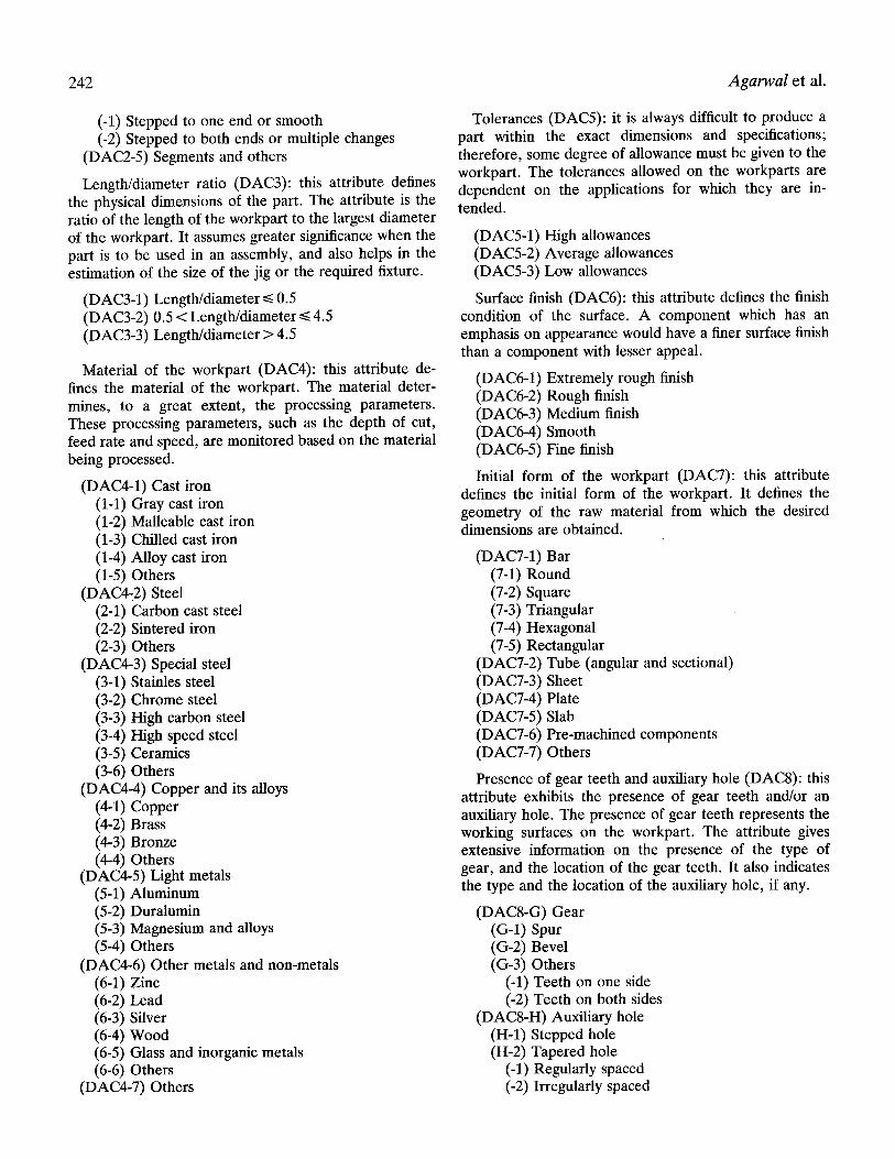
Length/diameter ratio (DAC3): this attribute defines the physical dimensions of the part. The attribute is the ratio of the length of the workpart to the largest diameter of the workpart. It assumes greater significance when the part is to be used in an assembly, and also helps in the estimation of the size of the jig or the required fixture.
Material of the workpart (DAC4): this attribute de- fines the material of the workpart. The material deter- mines, to a great extent, the processing parameters. These processing parameters, such as the depth of cut, feed rate and speed, are monitored based on the material being processed.
(DAC4-1) Cast iron (1-1) Gray cast iron (1-2) Malleable cast iron (1-3) Chilled cast iron (1-4) Alloy cast iron (1-5) Others
(DAC4-6) Other metals and non-metals (6-1) Zinc (6-2) Lead (6-3) Silver (6-4) Wood (6-5) Glass and inorganic metals (6-6) Others
(DAC4-7) Others
Tolerances (DAC5): it is always difficult to produce a part within the exact dimensions and specifications; therefore, some degree of allowance must be given to the workpart. The tolerances allowed on the workparts are dependent on the applications for which they are in- tended.
(DAC5-1) High allowances (DAC5-2) Average allowances (DAC5-3) Low allowances
Surface finish (DAC6): this attribute defines the finish condition of the surface. A component which has an emphasis on appearance would have a finer surface finish than a component with lesser appeal.
(DAC6-1) Extremely rough finish (DAC6-2) Rough finish (DAC6-3) Medium finish (DAC6-4) Smooth (DAC6-5) Fine finish
Initial form of the workpart (DAC7): this attribute defines the initial form of the workpart. It defines the geometry of the raw material from which the desired dimensions are obtained.
Presence of gear teeth and auxiliary hole (DAC8): this attribute exhibits the presence of gear teeth and/or an auxiliary hole. The presence of gear teeth represents the working surfaces on the workpart. The attribute gives extensive information on the presence of the type of gear, and the location of the gear teeth. It also indicates the type and the location of the auxiliary hole, if any.
An automated coding and classification system for effective design 243
(-3) Angular (-4) Others
Manufacturing attribute codes (MA): Number and type of processing steps (MAC1): this
attribute defines the number and type of processing steps that are required for obtaining the defined geometry. The number of processing steps chosen may not be optimal, but will be the number necessary to obtain the required geometry. After selection of the number of processing steps, the system will prompt the designer to input the types of the processes. The coding module is linked with the informative database to provide the designer with a list of the possible options associated with the selection made.
(MAC1-1) 1 (MAC1-2) 2 (MACI-3) 3 (MAC1-4) 4 (MAC1-5) 5 or more
Processing sequence (MAC2): this attribute is based on the number of operations chosen by the operator, and provides the optimal sequence of the operations to be performed. Once the number of operations is deter- mined, all the possible combinations of the operations are listed, and the operator can determine the sequence based on feasibility and operating conditions.
Processing parameters (MAC3): the performance of the machines and tools used, along with the requirements of surface finish, are determined by the processing parameters such as feed, speed and depth of cut. In order to obtain the desired dimensions, the operation is first selected and the process parameters are then chosen with respect to the system constraints. The operator inputs the values for speed, feed, and depth of cut, and the system assigns the code based on the range in which these values fall.
Type of machine used for processing (MAC4): this attribute provides information regarding the type of machine used for each of the above-mentioned opera- tions. The machine chosen may not be the best one for the operation, but the selection is based on availability and feasibility. For example,-if the operation chosen is drilling, the possible options are:
(M21-M-1) Column and upright drilling machine (M21-M-2) Gang drilling machine (M21-M-3) Radial drilling machine (M21-M-4) Multiple spindle drilling machine
Based on the required operation, the database provides a series of machine options. This attribute is also linked with the informative module and provides the designer
with a complete description of the processes and the required machines.
Jigs and fixtures (MAC5): this attribute provides in- formation regarding the holding devices. A jig is used in the drilling and boring operation, whereas a fixture is used in other operations.
(MAC5-2) Fixture (2-1) Special fixture (2-2) Multi-purpose fixture (2-3) Adjustable
(-1) Rotational (-2) Non-rotational
Required tooling (MAC6): this attribute informs the designer of the type of tooling required for the final geometry. The information depends on the type of operation chosen for the workpart and the type of machine being used for the option. For example, in the case of drilling operation, the available options are:
Similarly, based on the type of operation selected, the required tooling for the selected choices are defined.
Processing time (MAC7): this attribute defines the time required for performing all the required operations to obtain the final geometry. For example, if the selected operation is drilling, the time required is calculated using the following equation
T = L/(N,f) (11)
where T = Time required for the operation L = Length of the workpiece
244 Agarwal et al.
N = Spindle speed f = Feed (in/rev)
Similarly, the time required for all other operations is calculated using the appropriate formulation. The pro- cessing time is the sum of all the individual process times. The calculation is done using a spreadsheet, linked to the database. The code is based on the range of values as illustrated below.
(MAC7-1) 1-5 min (MAC7-2) 6-10 min (MAC7-3) 11-15 mln (MAC7-4) 16-20 mln (MAC7-5) 21-25 mm (MAC7-6) 26-30 mm (MAC7-7) 31-35 mm (MAC7-8) 36-40 mm (MAC7-9) 41--45 mm (MAC7-10) 46-50 mm (MAC7-11) 51-55 mm (MAC7-12) 56--60 mm (MAC7-13) 61 min and above
Batch volume (MAC8): this attribute provides in- formation regarding the number of workparts that need to be made. This information is considered important, since it is used to calculate the total machine operation cost. The operator inputs the value and the code is assigned based on the range in which the value falls. The selected range is as follows:
Required end operations (MAC9): this attribute in- forms the designer as to the type of end operations required. Most workparts require some sort of end operation, either to improve appearance, or to prepare for further operations. These are:
Machine operation cost (MAC10): this attribute gives
the total machine operation cost, which typically com- prises setup cost, operating cost and maintenance cost. The database is linked to the spreadsheet, which calcu- lates the cost. The digit is assigned based on the range in which the value falls. Operating cost is typically calcu- lated using the formula
OC = Ka K2 + 1(3 [(L rrDI'~)/(12CFr)] + 1(21(3 * [(LTrDT~-I)/ (12CFr)] + K 4 * [(L rrDT~-I)/(12CFr)] (12)
where K1, K2,/(3, K4 = Operating constants L = Length of the workpart under consideration D = Diameter of the workpart under consideration C = Cutting velocity for i min tool life (C = V,T") V = Cutting velocity Fr = Feed rate n = Index obtained from the Taylor's tool life equa-
tion T = Tool life.
An example of using this coding system is illustrated in Fig. 7. Some of the major features of the methodology used for the formation of part codes are:
(1) Provision of complete information--since the code is based on both the design and the manufacturing attributes, the part family code provides a comprehensive description of the part;
(2) Flexibility--the code is designed to have structure which is highly flexible. It provides the operator with various options and information at each stage of the code selection and assignment. The operator can also skip an attribute, as it may not be applicable to the workpart;
(3) Expandability--The database used for the coding system is designed to have structure in which the number of attributes can be easily increased and modified in order to provide for future expansion.
6.3. Part families formation
A module is linked to the database for the grouping of parts into families. The attributes selected for code assignment represent different types of variables. Three strategies are proposed by Anderberg (1973) as the possible solution approach for measuring the degree of association between objects with mixed variables types. One such approach is the use of 'disagreement indices'. Generally, four types of variable can be identified. These include binary, nominal, ordinal and continuous.
The linear disagreement index between parts i and j for attribute k, which is either a binary or nominal variable type, is measured by:
1, if Rik -q:: Rjk d i j k = (13)
0, otherwise
An automated coding and classification system for effective design 245
A t t r i b u t e s C o d e s Descr ip t ion
Design Attributes
General shape of the part 1 Rotational part
Basic shape 1-2 Stepped to Both Ends
Length/Diameter Ratio 2 0.5 < Length/Diameter <= 4.5
Material of the Workpart 2 Gro.y Cast Iron
Tolerances 2 Average Tolerances
Surface Finish 3 Medium Finish
Initial form of Workpart 1-1 Round Bar
Presence of Gear Teeth & N/A No Gear Teeth or Auxiliary Hole Auxiliary Hole
where NTjk = Number of tools~fixtures~jigs(k) required for machining part i NTqk = Number of tools~fixtures~jigs(k) common to both parts i and ]. The linear disagreement index for process and end
operation machines is calculated using the Hamming metric as follows (Kusiask, 1985):
dij k = Z a(Ximk, Xy, nk) (18) m
where Xim k = f 1, if part i uses machine m(k: processing or end)
0, otherwise
and ~(Simk, Xjmk) = I 1, if Sim k --/:: Sjmk [ 0, otherwise.
After evaluation of these parameters, the analyst can assign weights to represent his or her subjective evalua- tion of variables and can group parts based on their assigned priority. These weights can be categorized as:
Critical 1.0 Very important 0.75 Important 0.5 Not important 0.25
Finally, the weighted dissimilarity measure (DISq) be- tween parts i and j can be measured by
DISij = E (Wk*dijk)/E Wk (19) k k
where Wk = Weight assigned to attribute k(design or manufacturing) dqk = Disagreement index between parts i and j for attribute k
and DISij = Weighted dissimilarity coefficient be- tween parts i and j.
The linear disagreement indices for attributes DAC- 1,2,4,5,6,7,8 and MAC-1 are calculated using Equation 13, since they represent binary and nominal variables. The linear disagreement indices for attributes DAC-3 and MAC-3,7,8,10 are calculated using E q u a t i o n 14, since there is a class associated with these variables and therefore they are considered as ordinal variables. Equa- tion 16 is used to measure the linear dissimilarity index for attribute MAC-2. Equation 17 is used to measure these indices for attributes MAC-5 and 6, and Equation 18 for MAC-4,9 attributes.
After calculating the dissimilarity measure, the K- median technique is used to solve the grouping and part-families formation problem. To select the part- families in phase I of the methodology, the K-median model is reformulated as follows:
Coefficients p : Number of parts K: Required number of part families DISij: Dissimilarity measure between DlSij = DlSij
part i a n d j,
and, xq = I 1, if part i belong to group j
[ 0, otherwise
Model
Minimize E E DISij, xq i,j = 1, 2 . . . . . p q
(20)
An automated coding and classification system for effective design 247
'- Start . ~
1 1
Clear Variables
Read I GT Codes
L -"or Attribute's Weight
Identification
A
I - I + 1
~A Input / ttrlbute's I /
Rank /
Weight - 1
o
Weight • 0.75
Weight - 0.5
• /
Not Important 'l Weight - 0.25
Accumulate Wetghts
Attributes
Yes
Select Parts I & j
1 [ [ [ l
B
Dissimi lar i ty Index Value Calculation Baaed on The Variable Type o f At t r ibutes
1 1 1 1
Calculate Dissimilarity
Measures
Build 0-1 Integer
Model
1
No
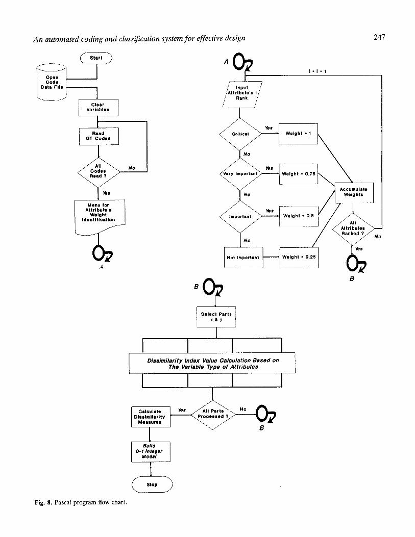
Fig. 8. Pascal p rogram flow chart.
248 Agarwal et al.
subject to
E x i J = l f o r a l l i = 1 , 2 , . . . , p (21) j=l , . . .p
E xjj = K (22) j=l , . . .p
xij <~ xjj for all i,j = 1 , 2 , . . . , p (23)
The first constraint, Equation 21, assures that each part belongs to only one family. The required number of part families is set in the second constraint, Equation 22. Parts are assigned to part families only if that part family has already been created. This is a conditional constraint and it is defined in Equation 23. The mathematical model presented is a 0-1 integer linear program. The model is solved using a branch and bound technique. The branch and bound technique is a partial enumeration method in which the set of solutions to a problem is examined by dividing this set into smaller subsets. It can be shown mathematically that some of these subsets do not contain the optimal solution. One important way in which a subset can be examined is to determine a bound. A bound of a subset is a value that is less than or equal to the value of all solutions contained in the subset. By comparing the bound of a subset with an already found solution, it is sometimes possible to eliminate the subset from further consideration.
A Pascal program is developed to assist the designer in calculating the parameters and in setting up the mathe- matical model formulation. The program will set up the model based on the LINDO software structure. This file is linked to the LINDO software for solution and analysis. The flow chart of this Pascal program is illustrated in Fig. 8.
7. Conclusion
This article illustrates a design overview of a hybrid coding and classification system and its supporting data- base implemented using dBASE-IV software. This pack- age is an interactive software system which allows the user to assign codes to the products. Each code is a string of characters capturing information about the part. The system is linked to a manufacturing process knowledge base which is used to assist the user during the coding process. The coding system utilized in this software allots an 18 digit code to each workpiece. The results of using this package are then used for the grouping of parts into families and the design of production cells. A further development of this package is the implementation of a variant process planning module which is currently under
development. The use of this system can increase control over both the design and the manufacturing stages. It also provides highly accurate and effective information to management, which will contribute to high productivity and cost saving.
References
Amirouche, F. M. L. (1993) Computer Aided Design and Manufacturing, Prentice-Hall, Englewood Cliffs, NJ.
Anderberg, M. R. (1973) Cluster Analysis for Applications, Academic Press, New York.
Bedworth, D., David, Henderson, R., Mark, Wolfe, M., Philip (1991) Computer Integrated Design and Manufacturing, McGraw-Hill, New York.
Billo, R. E., Ruker, R. and Shunk, D. L. (1987) Integration of a group technology classification and coding system with an engineering database. Journal of Manufacturing Systems, 6(1), 37-45.
Black, J. T. (1991) The Design of the Factory with a Future, McGraw-Hill, New York
Chang, T. C. and Wysk, R. A. (1985) An Introduction to Automated Process Planning Systems, Prentice-Hall, Englewood Cliffs, NJ.
Chang, T., Wysk, R. A. and Wang, H. (1991) Computer Aided Manufacturing, International series in Industrial and Sys- tem Engineering, Fabrycky, W. and Mize, J. (eds), Prentice-Hall, Englewood Cliffs, NJ.
Chu, C. and Pan, P. (1988) The use of clustering techniques in manufacturing cellular formation, in Proceedings of Inter- national Industrial Engineering Conference, liE, Toronto, Canada.
Degarmo, E. P., Black, J. T. and Kohser, R. A. (1984) Material and Processes in Manufacturing (6th ed.), Macmil- lan Publishing.
Dutta, S. P., Lashkari, R. S., Nadoli, G, and Ravi, T. (1986) A heuristic procedure for determining manufacturing families from design-based grouping for flexible manufacturing systems. Computer and Industrial Engineering, 10(3), 193- 201.
Eades, D. C. (1965) The inappropriateness of the correlation coefficient as a measure of taxonomic resemblance. Sys- tematic Zoology, 14, 98-100.
Goodall, D. W. (1966) A new similarity index based on probability. Biometrics, 22, 882-907.
Groover, M. P. (1987) Automation, Production Systems, and Computer Integrated Manufacturing, Prentice-Hall, Engle- wood Cliffs, NJ.
Groover, M. P. and Zimmers, Jr., E. W. (1980) Automation, Production Systems and Computer Aided Design, Prentice- Hall, Englewood Cliffs, NJ.
Houtzeel, A. and Schilperoort, B. A. (1976) A chain-structured part classification system (MICLASS) and group technolo- gy, in Proceedings of the 13th Annual Meeting and Technic- al Conference, Cincinnati, Ohio, March, pp. 383-400.
Kamrani, A. K. (1991) A methodology for forming machine cells in a computer integrated manufacturing environment
An automated coding and classification system for effective design 249
using group technology philosophy, Doctor of Philosophy Dissertation, University of Louisville, Louisville, KY.
Kusiak, A. (1985) The part families problem in flexible manufacturing systems. Annals of Operation Research, 279-300.
Kusiak, A. (1990) Intelligent Manufacturing Systems, Interna- tional Series in Industrial and Systems Engineering, Prentice-Hall, Englewood Cliffs, NJ.
McAuley, J. (1972) Machine grouping for efficient production, Production Engineer.
Opitz, H. (1970) A Classification System to Describe Work- pieces, Pergamon Press, New York.
Pavey, S. G., Hailstone, S. R. and Pratt, M. J. (1986) An automated interface between CAD and process planning, in Proceedings of the International Conference on Compu-
ter Aided Production Engineering, pp. 191-194. Senath, P. H. A. and Sokal, R. R. (1973) Numerical Tax-
onomy: The Principles and Practice of Numerical Clas- sification, Freeman Press, San Francisco.
SME (1983) Tool and Manufacturing Engineers Handbook. Snead, C. S. (1989) Group Technology: Foundation for Com-
petitive Manufacturing, Van Nostrand Reinhold, New York.
Wang, H. P. and Chang, H. (1987) Automated classification and coding based on extracted surface features in a CAD database. International Journal of Advanced Manufacturing Technology, 2(1), 25-38.
Willett, P. (1987) Similarity and Clustering in Chemical In- formation Systems, Wiley, New York.