International Journal of Machine Tools & Manufacture 40 (2000) 1755–1774 An experimental investigation of rotary diamond truing and dressing of vitreous bond wheels for ceramic grinding Albert J. Shih * Department of Mechanical and Aerospace Engineering, North Carolina State University, Raleigh, NC 27695-7910, USA Received 26 March 1999; received in revised form 14 February 2000; accepted 8 March 2000 Abstract Experiments of rotary diamond truing and dressing of vitreous bond grinding wheels were conducted to investigate the effects of feed, speed ratio, and overlap ratio on cylindrical grinding of zirconia. The applications of ceramic engine components with complex and precise form and the lack of technology for precision truing of diamond grinding wheels have driven the need to study the use of vitreous bond CBN and SiC wheels for form grinding of ceramics. Truing and grinding forces and the roundness and surface finish of ground zirconia parts were measured. By varying truing process parameters, a wide range of surface finish and roundness could be achieved. Experimental results showed that wheels trued at speed ratio below 21.0 could grind parts with fine surface finish and good roundness. The analysis of truing and grinding results showed the trend of increasing grinding force at higher specific truing energy and better surface finish at higher grinding force. The lack of speed control of the direct–drive, variable–speed truing spindle was observed and its effect on the reverse of direction of truing force at positive speed ratios was studied. 2000 Elsevier Science Ltd. All rights reserved. Keywords: Ceramic grinding; Truing; Dressing 1. Introduction Growing applications of structural ceramics have made grinding an important manufacturing process used to achieve the desired geometry and surface integrity of these hard, difficult to machine materials. The invention and production of superabrasives (diamond and CBN) in the 50s and 60s and the development of superabrasive wheels, truing devices, and grinding machines in the 70s and 80s have made the cost-effective machining of ceramics possible. Since the late * Tel.: + 1-919-515-5260; fax: + 1-919-515-7968. E-mail address: [email protected](A.J. Shih). 0890-6955/00/$ - see front matter 2000 Elsevier Science Ltd. All rights reserved. PII:S0890-6955(00)00022-5
Transcript
International Journal of Machine Tools & Manufacture 40 (2000) 1755–1774
An experimental investigation of rotary diamond truing anddressing of vitreous bond wheels for ceramic grinding
Albert J. Shih*
Department of Mechanical and Aerospace Engineering, North Carolina State University, Raleigh, NC 27695-7910,USA
Received 26 March 1999; received in revised form 14 February 2000; accepted 8 March 2000
Abstract
Experiments of rotary diamond truing and dressing of vitreous bond grinding wheels were conductedto investigate the effects of feed, speed ratio, and overlap ratio on cylindrical grinding of zirconia. Theapplications of ceramic engine components with complex and precise form and the lack of technology forprecision truing of diamond grinding wheels have driven the need to study the use of vitreous bond CBNand SiC wheels for form grinding of ceramics. Truing and grinding forces and the roundness and surfacefinish of ground zirconia parts were measured. By varying truing process parameters, a wide range ofsurface finish and roundness could be achieved. Experimental results showed that wheels trued at speedratio below21.0 could grind parts with fine surface finish and good roundness. The analysis of truing andgrinding results showed the trend of increasing grinding force at higher specific truing energy and bettersurface finish at higher grinding force. The lack of speed control of the direct–drive, variable–speed truingspindle was observed and its effect on the reverse of direction of truing force at positive speed ratios wasstudied. 2000 Elsevier Science Ltd. All rights reserved.
Keywords:Ceramic grinding; Truing; Dressing
1. Introduction
Growing applications of structural ceramics have made grinding an important manufacturingprocess used to achieve the desired geometry and surface integrity of these hard, difficult tomachine materials. The invention and production of superabrasives (diamond and CBN) in the50s and 60s and the development of superabrasive wheels, truing devices, and grinding machinesin the 70s and 80s have made the cost-effective machining of ceramics possible. Since the late
0890-6955/00/$ - see front matter 2000 Elsevier Science Ltd. All rights reserved.PII: S0890-6955(00)00022-5
1756 A.J. Shih / International Journal of Machine Tools & Manufacture 40 (2000) 1755–1774
Nomenclature
dw Diameter of the grinding wheelFtt Tangential truing forcefgt Specific tangential grinding forceh Width of plunger grindingqd Speed ratioRa Arithmetic average surface finishUd Overlap ratiout Specific truing energyva Traverse speed of the diamond truing disk across the grinding wheelvs Surface speed of the grinding wheelvt Surface speed of the truing diskwg Grinding powerwt Truing powerd Truing feed
80s, the use of structural ceramics in diesel engines has gradually expanded [1]. New ceramicengine components have more complicated shapes and tighter form tolerance specifications. Thishas driven the need to develop new form grinding technologies for ceramics.
For form grinding, a common and cost-effective method is to true the desired shape, usuallyat theµm-scale precision level, on a grinding wheel. This formed grinding wheel is then plungedto the workpiece, removing the unwanted work-material and generating the required geometry.Diamond, the hardest known material, has been the primary abrasive used in ceramic grinding.A metal-bond rotary diamond disk or formed diamond roll can be used to true the form ondiamond grinding wheels. Due to the high wear rate of the diamond tool, the truing of aµm-scale precision form on the vitreous bond diamond wheel is difficult [2]. In this study, besides adiamond wheel, vitreous bond CBN and SiC wheels were tested. The workpiece material wastransformation toughened zirconia. It is a ceramic material commonly used in diesel fuel systemsdue to its good tribological characters to prevent seizure in closely matched parts [1,3]. Thevitreous bond can be trued and dressed simultaneously. This type of wheel bond is ideal for high-volume production grinding [4] and has good control of tight form tolerances.
Figure 1 shows the hardness of three abrasives and the zirconia work-material. CBN and SiCwheels can be trued by a sharp, rotary diamond disk to theµm-scale precision level. However,the CBN abrasive is usually more expensive than the diamond and the CBN grinding wheel is,in general, more costly than the comparable diamond wheel. The hardness of SiC is limited andrepetitive truing and grinding may be necessary to generate the desired form on the zirconiaworkpiece. The high cost of CBN, low hardness of SiC, and lack of technology for precisiontruing the diamond wheels have hindered applications of structural ceramic components withcomplex form. This study is the first step to investigate the effects of rotary truing on CBN, SiC,and diamond grinding of zirconia ceramics.
Three rotary truing parameters investigated in this study are: feed, speed ratio (qd), and overlap
1757A.J. Shih / International Journal of Machine Tools & Manufacture 40 (2000) 1755–1774
Fig. 1. Comparison of the hardness of abrasives and zirconia work-material.
ratio (Ud). Feed is defined as the depth of removal of a layer of abrasive and bond materials fromthe surface of the wheel in each pass. For superabrasive wheels, the feed is usually very small,in the µm or sub-µm level, due to the high hardness of the abrasive. Speed ratio is defined asthe ratio of the truing disk surface speed,vt, divided by the grinding wheel surface speed,vs.
qd5vt
vs
(1)
qd can be positive (uni-directional or down-truing) or negative (counter-directional or up-truing).qd=1.0 is called the crush truing.
The width of contact between the truing disk and grinding wheel also influences truing andgrinding results. A parameter called overlap ratio,Ud, which is defined as the width of contactover the truing lead, is used to identify such effect. Two levels ofUd, high and low, were testedin this study. As shown in Fig. 2(a), the lowUd was achieved by tilting the truing spindle andusing the side of the diamond disk for truing. This enables truing at differentUd, using the sametruing disk. The exact width of contact was difficult to quantify and so was theUd. For the CBNand SiC wheels, truing at lowUd was possible. While truing the diamond wheel, the high wearrate of the diamond truing disk created a wide width of contact, as shown in Fig. 2(b), and madetruing at lowUd practically impossible.
Fig. 2. Truing with high and low overlap ratio. (a) Low overlap ratio (narrow width of contact), (b) high overlapratio (wide width of contact).
1758 A.J. Shih / International Journal of Machine Tools & Manufacture 40 (2000) 1755–1774
Early investigations of the effects of speed ratio, feed, and overlap ratio on rotary truing ofaluminum oxide wheels were carried out at the Technical University of Braunschweig [5–8] andby Malkin and Murray [9,10]. A number of papers studied the rotary truing and dressing of CBNwheels for grinding of steels [11–15]. Very limited information was available in truing and dress-ing of vitreous bond SiC or diamond wheels. Most of the papers provided only three to six truingspeed ratios in the experimental data, which could suggest a trend but did not give enough datafor statistical analysis. Most of the previous studies were conducted on surface grinding machines.Very limited results [14] on the effects of truing on cylindrical grinding are available. For ceramicgrinding, the experimental data of the effects of feed,qd, andUd on part roundness and surfacefinish is not available. This study is aimed to cover a wide range ofqd, over 1.0 and below21.0,to study the effects of rotary truing of vitreous bond CBN, SiC and diamond wheels on cylindricalgrinding of zirconia, and to analyze the truing and grinding results statistically.
In this paper, the experimental setup, which includes wheel truing and dressing, cylindricalgrinding of zirconia, and workpiece measurements, is presented first. The experimental designand grinding results, including truing and grinding forces and roundness and surface finish of theground ceramic parts, are compared and discussed. The truing and grinding results are then analyz-ed.
2. Experimental setup
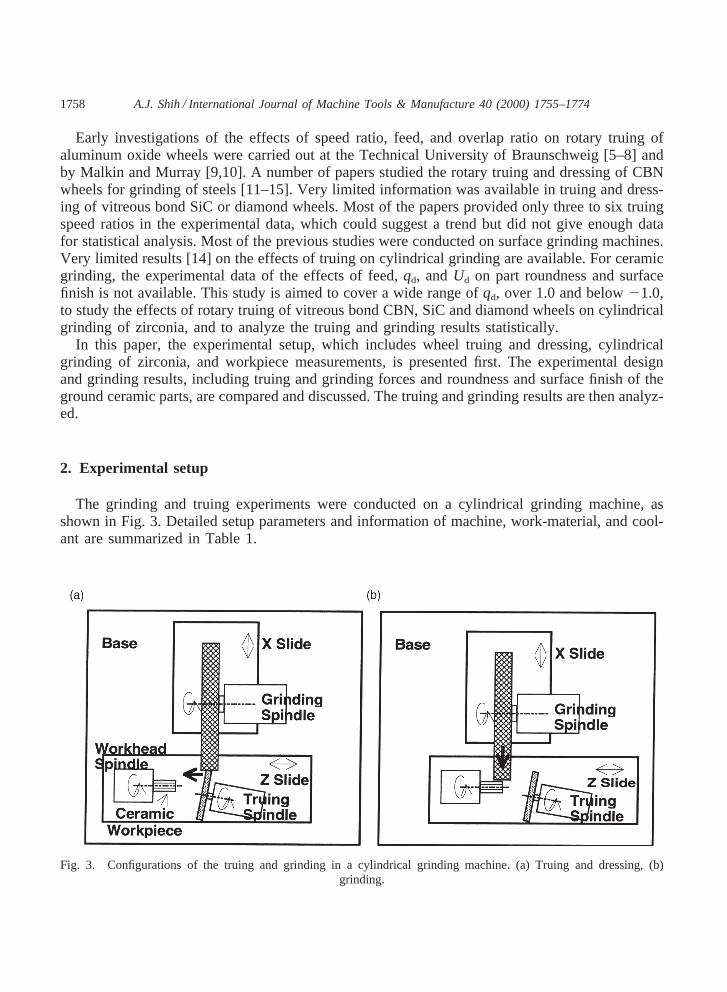
The grinding and truing experiments were conducted on a cylindrical grinding machine, asshown in Fig. 3. Detailed setup parameters and information of machine, work-material, and cool-ant are summarized in Table 1.
Fig. 3. Configurations of the truing and grinding in a cylindrical grinding machine. (a) Truing and dressing, (b)grinding.
1759A.J. Shih / International Journal of Machine Tools & Manufacture 40 (2000) 1755–1774
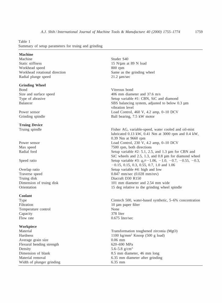
Table 1Summary of setup parameters for truing and grinding
MachineMachine Studer S40Static stiffness 15 N/µm at 89 N loadWorkhead speed 800 rpmWorkhead rotational direction Same as the grinding wheelRadial plunge speed 21.2µm/sec
Grinding WheelBond Vitreous bondSize and surface speed 406 mm diameter and 37.6 m/sType of abrasive Setup variable #1: CBN, SiC and diamondBalancer SBS balancing system, adjusted to below 0.3µm
Truing DeviceTruing spindle Fisher AG, variable-speed, water cooled and oil-mist
lubricated 0.13 kW, 0.41 Nm at 3000 rpm and 0.4 kW,0.39 Nm at 9660 rpm
Power sensor Load Control, 230 V, 4.2 amp, 0–10 DCVMax speed 7500 rpm, both directionsRadial feed Setup variable #2: 5.1, 2.5, and 1.3µm for CBN and
SiC wheels and 2.5, 1.3, and 0.8µm for diamond wheelSpeed ratio Setup variable #3:qd=21.06, 21.0, 20.7, 20.55, 20.3,
20.15, 0.15, 0.3, 0.55, 0.7, 1.0 and 1.06Overlap ratio Setup variable #4: high and lowTraverse speed 0.847 mm/sec (0.028 mm/rev)Truing disk Diacraft D30 R150Dimension of truing disk 101 mm diameter and 2.54 mm wideOrientation 15 deg relative to the grinding wheel spindle
CoolantType Cimtech 500, water-based synthetic, 5–6% concentrationFiltration 10 µm paper filterTemperature control NoneCapacity 378 literFlow rate 0.675 liter/sec
Dimension of blank 8.5 mm diameter, 46 mm longMaterial removal 6.35 mm diameter after grindingWidth of plunger grinding 6.35 mm
1760 A.J. Shih / International Journal of Machine Tools & Manufacture 40 (2000) 1755–1774
2.1. Wheel truing and dressing
The set up for rotary truing and dressing of grinding wheels is shown in Fig. 3(a). Two slides,X and Z, were used to position the grinding wheel for truing. The X slide was first positionedto get a specific feed in truing. The X slide then remained stationary when the Z slide traversedacross the grinding wheel. The wear in the truing disk could be significant at certainqd; therefore,at least six truing passes were conducted before each test. After the crush truing atqd=1.0, atleast twelve truing passes were conducted to ensure the grinding wheel was restored to the normalcondition. A stroboscope was used to calibrate the rotational speed of the spindles to within2% accuracy.
The selection of rotary truing device and process parameters can greatly impact truing andgrinding results. In this study, a frequency converter was used to alternate the three-phase ACfrequency to drive the truing spindle at different speeds. This type of direct–drive spindle, althoughmore expensive, is becoming more popular in superabrasive grinding machines than the traditionalhydraulic or electric-motor, belt-driven spindle because of its compact size and high speed capa-bility. The lack of speed control of this type of spindle and its effects on truing and grindingresults will be identified later.
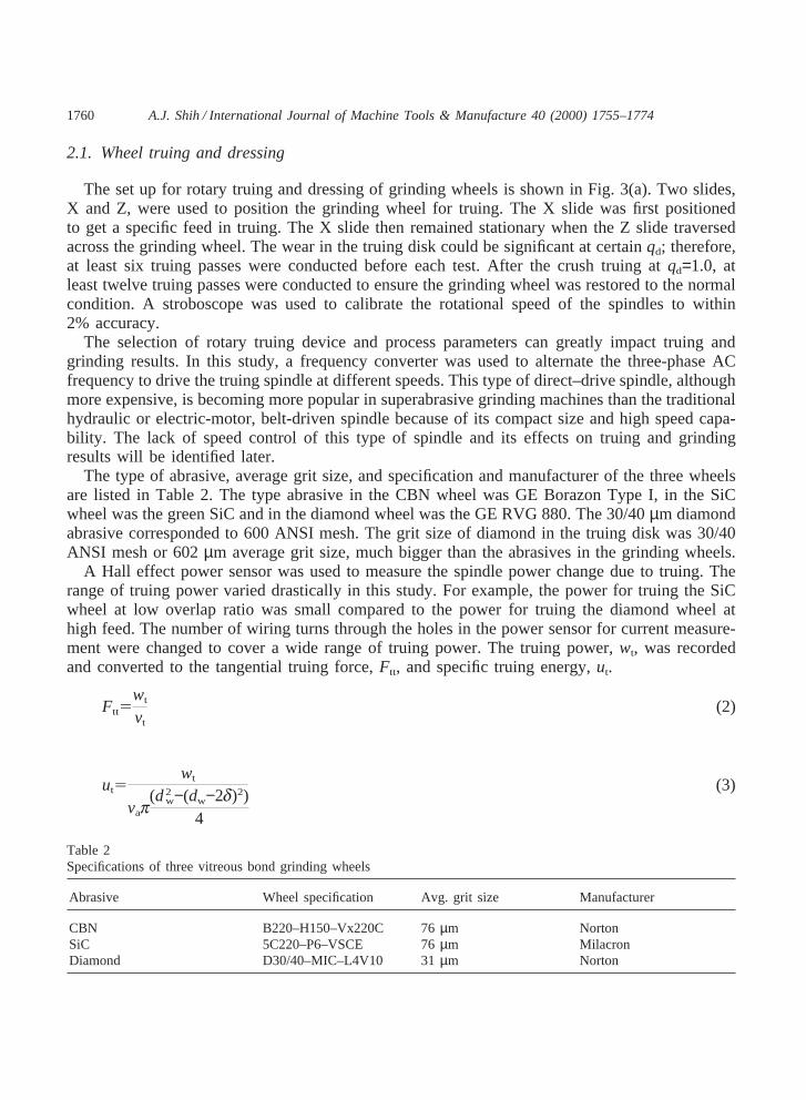
The type of abrasive, average grit size, and specification and manufacturer of the three wheelsare listed in Table 2. The type abrasive in the CBN wheel was GE Borazon Type I, in the SiCwheel was the green SiC and in the diamond wheel was the GE RVG 880. The 30/40µm diamondabrasive corresponded to 600 ANSI mesh. The grit size of diamond in the truing disk was 30/40ANSI mesh or 602µm average grit size, much bigger than the abrasives in the grinding wheels.
A Hall effect power sensor was used to measure the spindle power change due to truing. Therange of truing power varied drastically in this study. For example, the power for truing the SiCwheel at low overlap ratio was small compared to the power for truing the diamond wheel athigh feed. The number of wiring turns through the holes in the power sensor for current measure-ment were changed to cover a wide range of truing power. The truing power,wt, was recordedand converted to the tangential truing force,Ftt, and specific truing energy,ut.
Ftt5wt
vt
(2)
ut5wt
vap(d2
w−(dw−2d)2)4
(3)
Table 2Specifications of three vitreous bond grinding wheels
1761A.J. Shih / International Journal of Machine Tools & Manufacture 40 (2000) 1755–1774
whereva is the traverse speed of the diamond truing disk across the grinding wheel,dw is thediameter of the grinding wheel, andd is the radial feed in truing.
2.2. Cylindrical grinding of zirconia
After truing, the X and Z slides were positioned for cylindrical plunge grinding of the zirconiapart, as shown in Fig. 3(b). Grinding power was measured by another Hall effect power sensorfor the grinding spindle. The diameter of the ground surface and the specific material removalrate continued to reduce during the plunge grinding. Only the peak grinding power,wg, at thebeginning of the grinding was recorded. The peak specific tangential grinding force,fgt, can becalculated as:
fgt5wg
vsh(4)
whereh is the width of plunge grinding.
2.3. Workpiece measurements
The roundness of the ground parts was measured using a Mahr Perthen MFU8. A standardlow-pass Gaussian filter with 50 undulations per revolution was used. A 0.5 mm diameter carbideball was used for the stylus tip. Two roundness traces, 1 and 3 mm from the side, as shown laterin Fig. 9, were measured. The average of these two measurements was used to represent theroundness of the ground part.
Two surface finish traces were measured longitudinally on a Mahr Perthen S8P. Standard Gaus-sian filter with 0.8 mm cutoff length and 4.0 mm measurement length was used. The average oftwo arithmetic average surface finishes (Ra) was reported.
3. Experiment design and grinding results
Most of the parameters in Table 1 were set to remain the same. Only four parameters, i.e.,feed,qd, Ud, and type of abrasive, were varied to study their effects on grinding of zirconia.
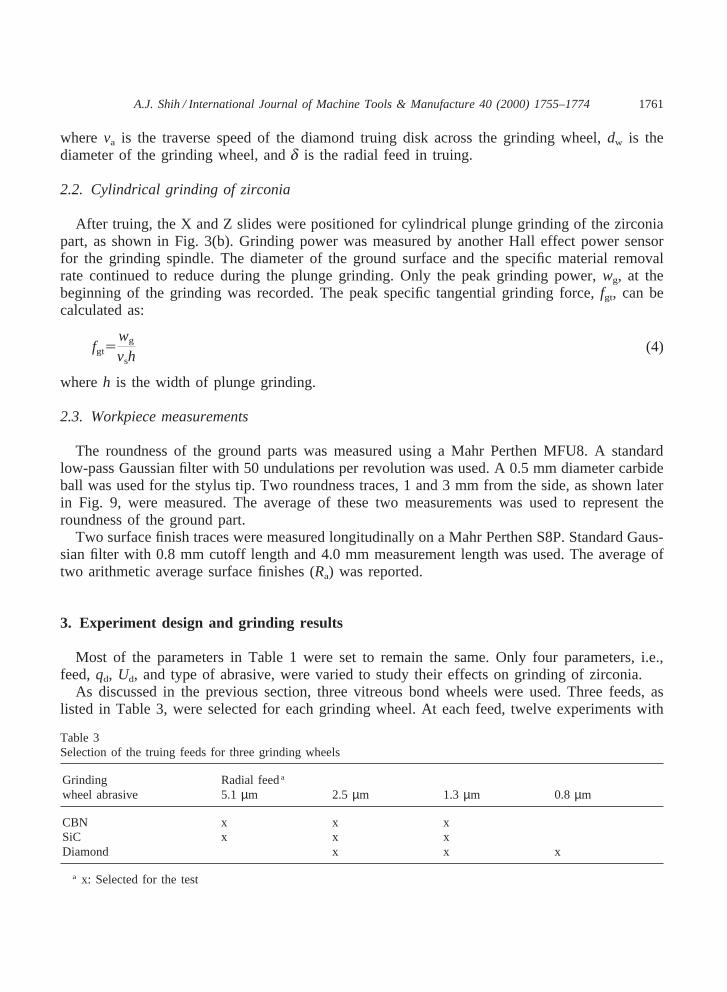
As discussed in the previous section, three vitreous bond wheels were used. Three feeds, aslisted in Table 3, were selected for each grinding wheel. At each feed, twelve experiments with
Table 3Selection of the truing feeds for three grinding wheels
Grinding Radial feeda
wheel abrasive 5.1µm 2.5 µm 1.3 µm 0.8 µm
CBN x x xSiC x x xDiamond x x x
a x: Selected for the test
1762 A.J. Shih / International Journal of Machine Tools & Manufacture 40 (2000) 1755–1774
differentqd, listed in Table 1, were conducted. Truing with high and low overlap ratios, as shownin Fig. 2, were tested for the CBN and SiC wheels. A total of 180 (5×3×12) truing and 180grinding experiments were carried out.
The experimental results for three grinding wheels are presented in Figs. 4–6. Each figuresummarizes the results for tangential truing force (Ftt), specific tangential grinding forces (fgt),surface finish (Ra), and roundness. The scale for each parameter was set to be the same in Figs.4–6 for mutual comparison.
3.1. Tangential truing force, ftt
The following four sections discuss the effects of each setup parameter on the tangential tru-ing force.
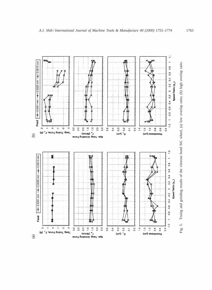
Fig. 4. Truing and grinding results of the vitreous bond CBN wheel, (a) low overlap ratio; (b) high overlap ratio.
1763A.J. Shih / International Journal of Machine Tools & Manufacture 40 (2000) 1755–1774
Fig
.5.
Tru
ing
and
grin
ding
resu
ltsof
the
vitr
eous
bond
SiC
whe
el,
(a)
low
over
lap
ratio
;(b
)hi
ghov
erla
pra
tio.
1764 A.J. Shih / International Journal of Machine Tools & Manufacture 40 (2000) 1755–1774
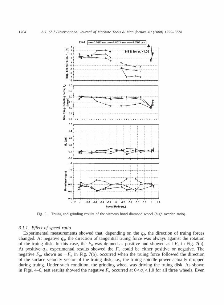
Fig. 6. Truing and grinding results of the vitreous bond diamond wheel (high overlap ratio).
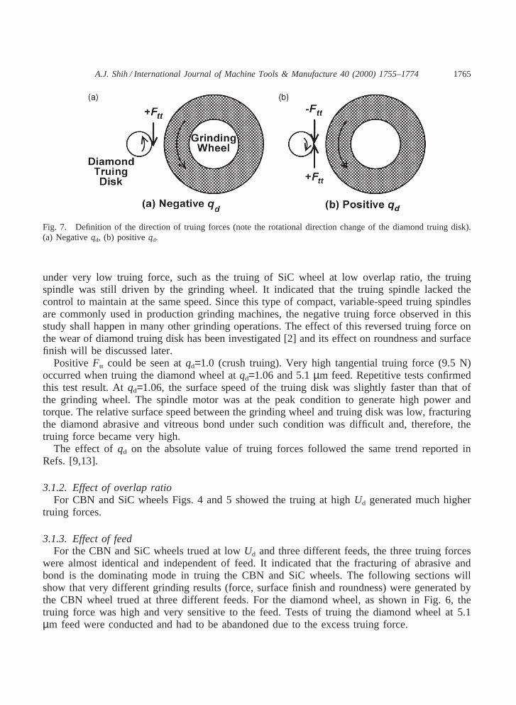
3.1.1. Effect of speed ratioExperimental measurements showed that, depending on theqd, the direction of truing forces
changed. At negativeqd, the direction of tangential truing force was always against the rotationof the truing disk. In this case, theFtt was defined as positive and showed as+Ftt in Fig. 7(a).At positive qd, experimental results showed theFtt could be either positive or negative. ThenegativeFtt, shown as2Ftt in Fig. 7(b), occurred when the truing force followed the directionof the surface velocity vector of the truing disk, i.e., the truing spindle power actually droppedduring truing. Under such condition, the grinding wheel was driving the truing disk. As shownin Figs. 4–6, test results showed the negativeFtt occurred at 0,qd,1.0 for all three wheels. Even
1765A.J. Shih / International Journal of Machine Tools & Manufacture 40 (2000) 1755–1774
Fig. 7. Definition of the direction of truing forces (note the rotational direction change of the diamond truing disk).(a) Negativeqd, (b) positiveqd.
under very low truing force, such as the truing of SiC wheel at low overlap ratio, the truingspindle was still driven by the grinding wheel. It indicated that the truing spindle lacked thecontrol to maintain at the same speed. Since this type of compact, variable-speed truing spindlesare commonly used in production grinding machines, the negative truing force observed in thisstudy shall happen in many other grinding operations. The effect of this reversed truing force onthe wear of diamond truing disk has been investigated [2] and its effect on roundness and surfacefinish will be discussed later.
PositiveFtt could be seen atqd=1.0 (crush truing). Very high tangential truing force (9.5 N)occurred when truing the diamond wheel atqd=1.06 and 5.1µm feed. Repetitive tests confirmedthis test result. Atqd=1.06, the surface speed of the truing disk was slightly faster than that ofthe grinding wheel. The spindle motor was at the peak condition to generate high power andtorque. The relative surface speed between the grinding wheel and truing disk was low, fracturingthe diamond abrasive and vitreous bond under such condition was difficult and, therefore, thetruing force became very high.
The effect ofqd on the absolute value of truing forces followed the same trend reported inRefs. [9,13].
3.1.2. Effect of overlap ratioFor CBN and SiC wheels Figs. 4 and 5 showed the truing at highUd generated much higher
truing forces.
3.1.3. Effect of feedFor the CBN and SiC wheels trued at lowUd and three different feeds, the three truing forces
were almost identical and independent of feed. It indicated that the fracturing of abrasive andbond is the dominating mode in truing the CBN and SiC wheels. The following sections willshow that very different grinding results (force, surface finish and roundness) were generated bythe CBN wheel trued at three different feeds. For the diamond wheel, as shown in Fig. 6, thetruing force was high and very sensitive to the feed. Tests of truing the diamond wheel at 5.1µm feed were conducted and had to be abandoned due to the excess truing force.
1766 A.J. Shih / International Journal of Machine Tools & Manufacture 40 (2000) 1755–1774
3.1.4. Effect of abrasive typeCompared to the CBN and SiC wheels, truing forces were high and wear on the diamond truing
disk was significant in the diamond wheel. The test data suggested that very small feed, in the 1µm level, should be used to true the diamond wheel using the diamond truing disk.
3.2. Specific tangential grinding force, fgt
The effects ofqd, feed, andUd on peak specific tangential grinding forces are discussed in thefollowing sections.
3.2.1. Effect of speed ratioThe effects ofqd on grinding forces have been studied [5,9,13]. Truing at higherqd tends to
increase the abrasive fracture on the vitreous bond wheels and generate lower grinding forces androugher workpiece surface finish. For cylindrical grinding of zirconia, this trend was apparent forthe CBN wheel and not obvious for the SiC wheel, especially at low overlap ratio. For the diamondwheel, this trend was more apparent during truing at the smallest, 0.8µm feed and not obviousat higher feeds.
The trend of loweringfgt at high qd reversed atqd=1.0. Compared to thefgt at qd=1.0, truingat qd=1.06, in general, generated higherfgt.
3.2.2. Effect of feedExperiments showed that larger truing feeds created more macro-fracturing on the CBN abras-
ive, which, in turn, generated a wheel topography with sharp cutting edges and low grindingforces [15]. Such practice worked for the CBN wheel and the SiC wheel trued at lowUd. Adifferent trend could be seen on the diamond wheel and the SiC wheel trued at highUd, i.e.,truing at higher feed actually dulled the abrasive and generated higher grinding forces. For theSiC wheel truing at highUd and 1.3µm feed, the analysis in Section 4.2 will reveal that thestrength of vitreous bond in the SiC wheel was not strong enough to hold the abrasive for grindingzirconia. During grinding, the SiC grain was pulled out which generated lower grinding force.For the diamond wheel, instead of fracturing the diamond abrasive for more efficient grinding,the attritious wear of the diamond on the grinding wheel and truing disk is more dominating.Thus, truing at higher feed did not generate lower grinding forces.
3.2.3. Effect of overlap ratioThe CBN wheel trued at low overlap ratio generated lowfgt. Such effect was not obvious for
the SiC wheel.
3.3. Surface finish, Ra
Figs. 4–6 also showed the averagedRa for the cylindrically ground zirconia. The effect ofqd
on the part surface finish has been investigated by Klocke and Koenig [13] and Jakobuss andWebster [14] for CBN grinding of steels.
1767A.J. Shih / International Journal of Machine Tools & Manufacture 40 (2000) 1755–1774
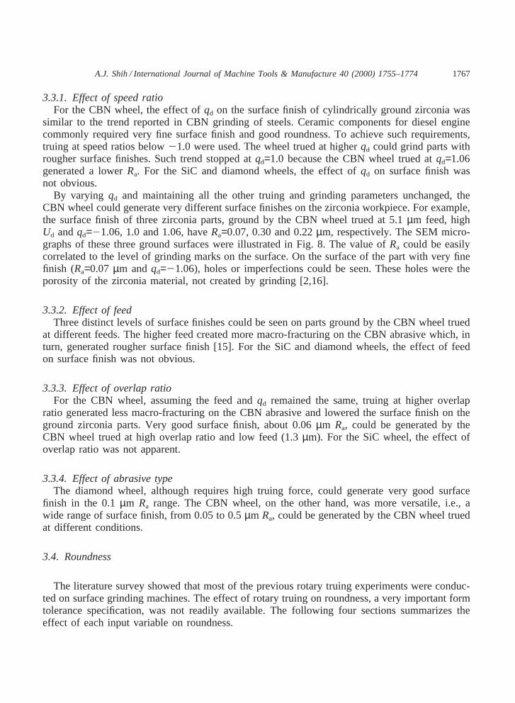
3.3.1. Effect of speed ratioFor the CBN wheel, the effect ofqd on the surface finish of cylindrically ground zirconia was
similar to the trend reported in CBN grinding of steels. Ceramic components for diesel enginecommonly required very fine surface finish and good roundness. To achieve such requirements,truing at speed ratios below21.0 were used. The wheel trued at higherqd could grind parts withrougher surface finishes. Such trend stopped atqd=1.0 because the CBN wheel trued atqd=1.06generated a lowerRa. For the SiC and diamond wheels, the effect ofqd on surface finish wasnot obvious.
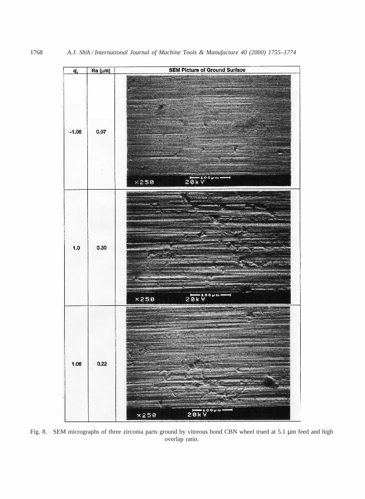
By varying qd and maintaining all the other truing and grinding parameters unchanged, theCBN wheel could generate very different surface finishes on the zirconia workpiece. For example,the surface finish of three zirconia parts, ground by the CBN wheel trued at 5.1µm feed, highUd andqd=21.06, 1.0 and 1.06, haveRa=0.07, 0.30 and 0.22µm, respectively. The SEM micro-graphs of these three ground surfaces were illustrated in Fig. 8. The value ofRa could be easilycorrelated to the level of grinding marks on the surface. On the surface of the part with very finefinish (Ra=0.07 µm andqd=21.06), holes or imperfections could be seen. These holes were theporosity of the zirconia material, not created by grinding [2,16].
3.3.2. Effect of feedThree distinct levels of surface finishes could be seen on parts ground by the CBN wheel trued
at different feeds. The higher feed created more macro-fracturing on the CBN abrasive which, inturn, generated rougher surface finish [15]. For the SiC and diamond wheels, the effect of feedon surface finish was not obvious.
3.3.3. Effect of overlap ratioFor the CBN wheel, assuming the feed andqd remained the same, truing at higher overlap
ratio generated less macro-fracturing on the CBN abrasive and lowered the surface finish on theground zirconia parts. Very good surface finish, about 0.06µm Ra, could be generated by theCBN wheel trued at high overlap ratio and low feed (1.3µm). For the SiC wheel, the effect ofoverlap ratio was not apparent.
3.3.4. Effect of abrasive typeThe diamond wheel, although requires high truing force, could generate very good surface
finish in the 0.1µm Ra range. The CBN wheel, on the other hand, was more versatile, i.e., awide range of surface finish, from 0.05 to 0.5µm Ra, could be generated by the CBN wheel truedat different conditions.
3.4. Roundness
The literature survey showed that most of the previous rotary truing experiments were conduc-ted on surface grinding machines. The effect of rotary truing on roundness, a very important formtolerance specification, was not readily available. The following four sections summarizes theeffect of each input variable on roundness.
1768 A.J. Shih / International Journal of Machine Tools & Manufacture 40 (2000) 1755–1774
Fig. 8. SEM micrographs of three zirconia parts ground by vitreous bond CBN wheel trued at 5.1µm feed and highoverlap ratio.
1769A.J. Shih / International Journal of Machine Tools & Manufacture 40 (2000) 1755–1774
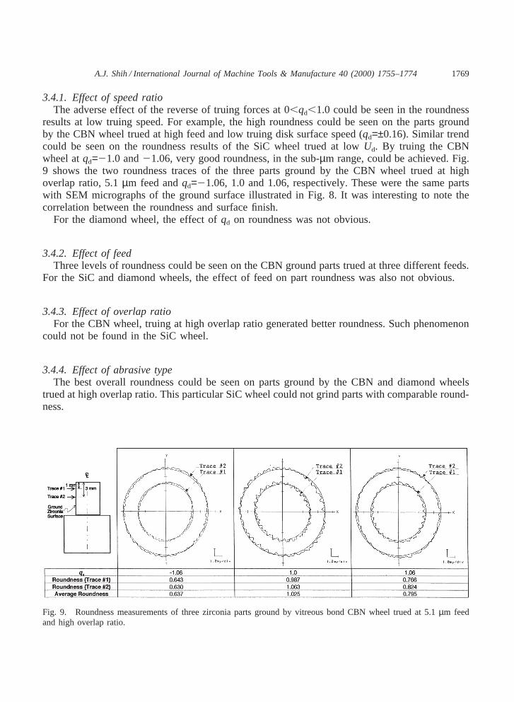
3.4.1. Effect of speed ratioThe adverse effect of the reverse of truing forces at 0,qd,1.0 could be seen in the roundness
results at low truing speed. For example, the high roundness could be seen on the parts groundby the CBN wheel trued at high feed and low truing disk surface speed (qd=±0.16). Similar trendcould be seen on the roundness results of the SiC wheel trued at lowUd. By truing the CBNwheel atqd=21.0 and21.06, very good roundness, in the sub-µm range, could be achieved. Fig.9 shows the two roundness traces of the three parts ground by the CBN wheel trued at highoverlap ratio, 5.1µm feed andqd=21.06, 1.0 and 1.06, respectively. These were the same partswith SEM micrographs of the ground surface illustrated in Fig. 8. It was interesting to note thecorrelation between the roundness and surface finish.
For the diamond wheel, the effect ofqd on roundness was not obvious.
3.4.2. Effect of feedThree levels of roundness could be seen on the CBN ground parts trued at three different feeds.
For the SiC and diamond wheels, the effect of feed on part roundness was also not obvious.
3.4.3. Effect of overlap ratioFor the CBN wheel, truing at high overlap ratio generated better roundness. Such phenomenon
could not be found in the SiC wheel.
3.4.4. Effect of abrasive typeThe best overall roundness could be seen on parts ground by the CBN and diamond wheels
trued at high overlap ratio. This particular SiC wheel could not grind parts with comparable round-ness.
Fig. 9. Roundness measurements of three zirconia parts ground by vitreous bond CBN wheel trued at 5.1µm feedand high overlap ratio.
1770 A.J. Shih / International Journal of Machine Tools & Manufacture 40 (2000) 1755–1774
4. Data analysis
The results presented in Figs. 4–6 are further analyzed to find the correlation between variablesand to gain better understanding of truing and grinding processes.
4.1. Specific truing energy, ut
The specific truing energy for rotary truing of aluminum oxide wheels has been studied byMalkin and Murray [9]. Fig. 10 illustrates the variation ofut vs. qd. As discussed in Section 2.1,the range ofut varied drastically and the logarithmic scale was used.
Fig. 10. Specific truing energy of three vireous bond grinding wheels.
1771A.J. Shih / International Journal of Machine Tools & Manufacture 40 (2000) 1755–1774
4.1.1. Effect of speed ratioTruing at slower truing wheel surface speeds generated lowerut. It was misleading to conclude
that low speed truing was more efficient. At low truing speed, the truing spindle could not generateenough power for efficient truing of grinding wheels.
4.1.2. Effect of feedFor CBN and SiC wheels, large feed generated lowerut, which was consistent with the results
reported by Malkin and Murray [9]. For the diamond wheel, the feed had less significant effecton ut.
4.1.3. Effect of overlap ratioTruing at lowUd was more efficient and generated lowerut because the friction force between
truing disk and grinding wheel was reduced.
4.1.4. Effect of abrasive typeThe hardness of abrasives has definite impact on theut. The level ofut corresponded to the
hardness of the abrasive in the grinding wheel.
4.2. Specific tangential grinding force vs. Specific truing energy
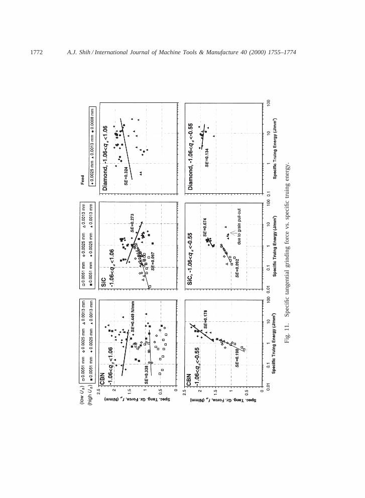
Fig. 11 shows the specific tangential grinding force (fgt) vs. specific truing energy (ut). Thelinear regression analysis was used to find a best-fit line for the data points. A parameter in linearregression analysis called Standard Error (SE), similar to the standard deviation in the Gaussiandistribution, was used to quantify the spread of data points [17].
As shown in the top three graphs in Fig. 11, if the data across all speed ratios (21.06#qd#1.06)were examined, the scattering of data was wide (high SE). If the range ofqd was narrowed tobetween20.55 and21.06, as shown in the bottom three graphs in Fig. 11, a clear trend ofincreasingfgt at higherut could be identified for the CBN and SiC wheels. Much lower SE couldbe seen in the data for21.06#qd#20.55. It showed the performance of truing spindle was criticalin the correlation ofut and fgt. It also showed truing at higherut dulled the grinding wheel andgenerated higherfgt. A lower ut indicated more fracture of the abrasive grain during truing. Itgenerated lowerfgt. For the diamond wheel, thefgt remained in about the same level, independentof the ut.
The four data points for the SiC wheel trued at 1.3µm feed, showed by the solid triangularmark in the middle lower graph in Fig. 11, were located below the trend line. It could be explainedas: the SiC wheel trued at the lowest feed (1.3 vs. 2.5 and 5.1µm) was supposed to have highergrinding forces; however, the bond in the SiC wheel could not withstand such high grinding forcesand the SiC grains was pulled out of the bond during grinding. This resulted lower grinding forces.
4.3. Surface finish vs. Specific tangential grinding force
The influence of specific tangential grinding force on part surface finish was investigated inFig. 12. The trend of better surface finish at higher grinding force could be seen on all threegrinding wheels. For the CBN and SiC wheels, across the twelve speed ratios, two best-fit lines
1772 A.J. Shih / International Journal of Machine Tools & Manufacture 40 (2000) 1755–1774
Fig
.11
.S
peci
ficta
ngen
tial
grin
ding
forc
evs
.sp
ecifi
ctr
uing
ener
gy.
1773A.J. Shih / International Journal of Machine Tools & Manufacture 40 (2000) 1755–1774
Fig. 12. Surface finish vs. specific tangential grinding forces.
were used to represent the data at eachUd. At low Ud, the reduction in surface finish due to thechange infgt was more significant.
Compared to the data in the CBN wheel, the spread of the data points was wider for SiC anddiamond wheels. The same trend of better surface finish at higherfgt could still be seen. For thediamond wheel, the close to horizontal best-fit line indicated that the influence of grinding forceon surface finish was not significant.
5. Concluding remarks
A total of 180 truing and 180 grinding experiments were carried out to investigate the effectsof rotary truing feed and speed ratio on three vitreous bond wheels for cylindrical grinding ofzirconia. A wide range of grinding forces, surface finishes, and roundness could be generated by
1774 A.J. Shih / International Journal of Machine Tools & Manufacture 40 (2000) 1755–1774
varying the truing process parameters. This is an advantage of vitreous bond wheels that grindingresults can be tailored by adjusting truing parameters. On the contrary, it is also a disadvantageof the vitreous bond wheels because a truing process has to be developed along with the grind-ing process.
This study extended the speed ratios to below21.0, an area that few researchers have pre-viously investigated. The CBN wheel trued under such conditions generated high grinding forcesand very good surface finish (about 0.06µm Ra) and roundness (about 0.6µm), which weredesirable for some ceramic components. The data of truing forces showed the grinding wheelwas driving the diamond truing disk when the speed ratios were between 0 and 1.0.
The results presented in this study could be applied to the cylindrical grinding machines withcomparable stiffness and setup. Depending on the stiffness and condition of the grinding machine,the truing and grinding results will change. However, it is important to point out that the trendidentified in this systematic truing and grinding study can be applied in the practical ceramicgrinding process development to achieve desired part surface finish and roundness.
References
[1] W.F. Mandler, T.M. Yonushonis, K. Shinosawa, 6th International Symposia on Ceramic Materials and Compo-nents for Engines, Arita-Machi, Japan, (1997) p. 137.
[2] A.J. Shih, Machining Science and Technology 2 (1998) 13.[3] S. Jahanmir (Ed.), Friction and Wear of Ceramics Marcel Dekker, New York, 1994.[4] D.J. Gust, A.J. Shih, M. Tricard, S. Subramanian, Proceedings of the 1996 ASME International Mechanical Engin-
eering Congress and Exposition ASME MED 4 (1996) 281.[5] G. Pahlitzsch, R. Schmitt, Werkstattstechnik, Z. Ind. Fertigung 59 (1969) 158.[6] H. Schneidemann, Dr.Ing. Dissertation, Braunschweig Technical University (1973).[7] H. Meyer, H. Wiemann, Proceedings, Diamonds-Partner in Production, (1984), p. 159.[8] E. Salje, C. Milton, Shaw Grinding Symposium ASME PED 16 (1985) 59.[9] S. Malkin, T. Murray, J. Engng. Ind. 100 (1978) 95.
[10] T. Murray, S. Malkin, J. Engng. Ind. 100 (1978) 297.[11] E. Salje, U. Harbs, Annals CIRP 39 (1) (1990) 337.[12] K. Subramanian, R.P. Lindsay, J. Engng. Ind. 114 (1992) 41.[13] F. Klocke, W. Koenig, Annals CIRP 44 (1) (1995) 305.[14] M. Jakobuss, J. Webster, Abrasives, Aug–Sep. 22 (1996).[15] T. Ishikawa, K. Kumar, Superabrasive ’91, (1991), pp. 7–91.[16] M. Tricard, D.J. Gust, A.J. Shih, Machining Science and Technology 3 (1999) 201.[17] D. Harnett, Statistical Methods (3rd ed), Addison Wesley, 1982.