Page 1
1
An Experimental Study of a Novel Integrated Desiccant1
Air Conditioning System for Building Applications2
3
Theo Elmera*, Mark Woralla, Shenyi Wua and Saffa Riffata4aArchitecture, Energy and Environment Research Group, The University of Nottingham, UK5
*corresponding author email: [email protected]
*corresponding author telephone: + 44 (0)7500 831 1787
8
Abstract9
To date, the application of liquid desiccant air conditioning systems in built environment10
applications, particularly small scale, has been limited. This is primarily due to large11
system size and complexity, issues of desiccant solution leakage and carry-over and12
equipment corrosion. As a result, a novel integrated desiccant air conditioning system13
(IDCS) has been developed. The system combines the regenerator, dehumidifier and14
evaporative inter-cooler into a single membrane based heat and mass exchanger. This15
paper presents an evaluation, based on experimental data, of the novel IDCS operating16
with a potassium formate (CHKO2) desiccant working fluid. A range of tests have been17
completed to characterise the performance of the dehumidifier, regenerator and18
complete IDCS. Cooling output in the range of 570 to 1362W and dehumidifier19
effectiveness in the range of 30 to 47% are presented. An issue encountered has been20
an imbalance between moisture removal rate in the dehumidifier and moisture addition21
rate in the regenerator. As a result, an adjusted thermal COP (COPth,adj) value has been22
calculated. COPth,adj values of 1.26 have been achieved with an average of 0.72.23
Electrical COP (COPel) values of 3.67 have been achieved with an average of 2.5.24
25
The work demonstrates that the novel IDCS concept is viable and has provided progress26
to the field of liquid desiccant air conditioning technology for building applications.27
Further work is required in order to address the main issue of mass imbalance between28
the dehumidifier and regenerator.29
30
Keywords: Liquid desiccant, air conditioning, integrated design, building application,31
potassium formate.32
33
Page 2
2
1 Introduction34
Buildings use significant quantities of energy, and thus they are a great contributor to35
CO2 emissions. Heating, ventilation and air conditioning (HVAC) systems are a major36
source of this energy use in buildings, accounting for around 50% of total supplied37
energy [1]. Air conditioning is a major function within HVAC systems, and is widely used38
in a range of buildings such as homes, schools, supermarkets and sport centres.39
Although air conditioning has become a part of people’s life needs in many Middle East,40
Far East, American and Southern European regions, it has more recently received41
growing use in Northern European countries, such as the UK, Denmark and Germany.42
This is due to more frequent warm spells, improved building insulation / air tightness43
and the use of in-house heat generating appliances [2].44
45
Currently, the air conditioning market is dominated by vapour compression systems46
(VCS) because they have good stability in performance, low cost, long life and a47
reasonable electrical COP (COPel) of between 2 – 4 [3]. However, VCS make use of48
harmful refrigerants such as R-22, R-410A, R-134A, materials with high global warming49
potential [4], and use significant quantities of electrical energy to drive the compressor.50
Owing to the fact that the most common form of electrical generation in the majority of51
counties is from the combustion of fossil fuels, VCS can be viewed as neither a52
sustainable nor efficient air conditioning option [5]. It is thus apparent, with an already53
high and continually growing global demand for air conditioning there is a need for54
alternative options that do not rely so heavily on harmful working fluids and fossil fuel55
derived electrical energy.56
57
1.1 Alternative air conditioning technologies58
There are a variety of alternative air conditioning systems; foremost amongst these are59
the sorption technologies, which reduce the requirement of electrical energy, but in place60
of this, increase the demand for thermal energy to operate. This thermal energy can be61
sourced from waste (process), solar, fuel cell etc. Thus, the associated CO2 emissions in62
waste heat driven cooling cycles will be lower than an equivalent VCS, primarily due to a63
reduction in electrical requirement and the utilisation of waste/renewable heat for a64
useful process.65
66
Closed cycle vapour absorption systems (VAS) replace the electrical driven compressor67
found in a VCS with a heat driven absorber and generator, these act in combination as a68
thermal compressor. VAS have a relatively low thermal COP (COPth), in the range of 0.569
Page 3
3
in single effect cycles up to 1.2 in double effect cycles [3, 6], which results in the70
intensive use of thermal energy. Furthermore, due to pressurised operation, the need for71
high temperature waste heat, expensive and corrosive chemical solutions, e.g., LiCl,72
LiBr, CaCl2, VAS are relatively large and complex, and this has limited their attraction to73
many users [7] and to applications greater than 10kW [8]. Thus, a VAS cannot be74
viewed as a viable option, particularly for smaller (domestic) building applications.75
76
An alternative to closed cycle vapour absorption is open cycle vapour absorption; also77
known as desiccant air conditioning. Desiccant air conditioning utilises the capability of78
desiccant materials to remove moisture from an air stream by the natural sorption79
process. Desiccant systems operate at atmospheric pressure and can either be solid80
(adsorption) or liquid (absorption). Both types have their advantages and disadvantages.81
Liquid desiccants have lower regeneration temperatures, greater dehumidification82
capacity and a lower air side pressure drop. Solid desiccants systems are compact,83
simple, less subject to desiccant carryover and corrosion [9]. In this paper a liquid84
desiccant system is presented.85
86
A liquid desiccant air conditioning system consists of three main components: (1)87
dehumidifier (2) regenerator / regeneration heat source, and (3) an optional sensible88
cooling device. The role of the dehumidifier is to reduce the moisture content and89
temperature of supply air to provide a comfortable building environment for occupants.90
As moisture is absorbed by the liquid desiccant solution it becomes dilute and its ability91
to absorb moisture is reduced. In order to re-use the desiccant solution, a regenerator is92
used to evaporate off the moisture gained, thus increasing its concentration. The93
desiccant solution needs to be cooled prior to it being re-used in the dehumidifier. This is94
to enhance the dehumidification capacity of the solution and/or provide air sensible95
cooling. The solution / air sensible cooling process is most commonly achieved through96
evaporative means and can be a separate or con-current process to dehumidification.97
98
The most commonly used liquid desiccant solutions used in air conditioning applications99
are known as halide salts, these include, Lithium Chloride (LiCl), Lithium Bromide (LiBr)100
and Calcium Chloride (CaCl2). Advantages of these materials are they are there strong101
desiccants. LiBr and LiCl can dry air to a relative humidity of 6% and 11% respectively102
[10]. However the halide salts are extremely corrosive and cause significant damage to103
air conditioning equipment (heat exchangers, pipes etc.). Titanium is one of the few104
materials that can be used, however it is very expensive. In response to the105
shortcomings of the halide salts, other options have been explored. Salts of weak106
Page 4
4
organic acids such as potassium formate (CHKO2) or sodium formate (HCOONa) have107
been used [11]. These solutions have low toxicity and viscosity, are neither corrosive nor108
volatile, and they can, at the correct concentrations achieve sufficient dehumidification109
for comfort air conditioning in building applications. The concentration of CHKO2 for air110
conditioning applications needs to be greater than that of the halide salts. For instance111
CHKO2 at a 50% solution mass concentration is equivalent to the dehumidification112
potential of LiCl at a 27% solution mass concentration. Although it is a weaker desiccant113
than the halide salts, CHKO2 ability to dehumidify air below 30% relative humidity and114
its favourable physical characteristics makes it an attractive option for building air115
conditioning applications [10].116
117
A recent study of a liquid desiccant enhanced evaporative air conditioning system118
demonstrated a 30 – 90 % reduction in energy demand compared to an equivalent VCS119
[12]. Desiccant systems are currently competing in applications with large latent loads120
such as supermarkets and where high humidity may cause damage to property such as121
storage areas [11]. Although extensive work has been carried out on liquid desiccant air122
conditioning [13-17], system complexity and large geometrical size has severely limited123
their wider application and outweighed the significant energy savings they can achieve124
[9]. There is therefore a great need for simpler, more compact systems, particularly for125
building applications where space is often limited. Another major issue reported with126
liquid desiccant air conditioning systems is carry-over of the liquid desiccant solution into127
the supply airstream. This presents a health hazard to occupants and a corrosion risk for128
air conditioning plant and building. Liquid desiccant carry-over may be eliminated with129
the introduction of a semi permeable micro-porous membrane which allows the diffusion130
of water vapour but prevents the liquid desiccant solution migrating across it [18].131
132
In response to these operational issues, a novel IDCS has been developed with the aim133
of permitting effective integration of liquid desiccant air conditioning in building134
applications. The novel IDCS has three design characteristics that aim to address the135
issues of system size and complexity, desiccant solution leakage and carry-over and136
equipment corrosion.137
138
(1) A novel stack design integrates the regenerator, dehumidifier and evaporative139
inter-cooler into a single heat and mass exchanger (HMX), making the whole140
system more compact and less prone to leakage. The IDCS has less piping, heat141
exchangers and pumps compared to an equivalent conventional ‘separate’142
system.143
Page 5
5
(2) The use of a semi-permeable micro porous membrane in the dehumidifier and144
regenerator HMX cores to prevent desiccant entrainment into the supply /145
working airstreams.146
(3) Employment of an environmentally friendly, non-corrosive and low cost CHKO2147
desiccant solution.148
149
This paper presents an evaluation, based on experimental data, of the novel IDCS150
operating with a CHKO2 desiccant working fluid. No previous work has been found in the151
literature regarding an integrated design of this type. The work presented provides152
progress to the field of liquid desiccant air conditioning technology for building153
applications.154
155
2 Experimental set-up156
As previously stated, space, complexity and leakage is often cited as a significant barrier157
to the wider use of liquid desiccant air conditioning in buildings. As a result, an efficient158
and compact liquid desiccant system has been designed and built. The regenerator159
(R/C), dehumidifier (D/C) and evaporative inter-cooler (E/C) are combined into one160
single HMX core. The membrane HMX runs the entire length of the unit, but is161
subdivided into three different airflows, and two different fluid flows; desiccant and162
water. Thermal input to the regenerator is achieved through the heating of the inlet163
airstream in a liquid to air heat exchanger. Figure 1 shows a schematic of the integrated164
unit design concept. This design significantly reduces the number of heat exchangers,165
pipes and ducting often seen in liquid desiccant air conditioning systems, therefore166
reducing its total footprint.167
168
169
Figure 1 The novel IDCS concept170
171
Page 6
6
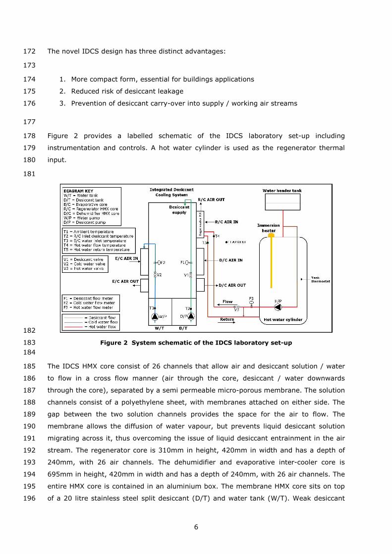
The novel IDCS design has three distinct advantages:172
173
1. More compact form, essential for buildings applications174
2. Reduced risk of desiccant leakage175
3. Prevention of desiccant carry-over into supply / working air streams176
177
Figure 2 provides a labelled schematic of the IDCS laboratory set-up including178
instrumentation and controls. A hot water cylinder is used as the regenerator thermal179
input.180
181
182
Figure 2 System schematic of the IDCS laboratory set-up183
184
The IDCS HMX core consist of 26 channels that allow air and desiccant solution / water185
to flow in a cross flow manner (air through the core, desiccant / water downwards186
through the core), separated by a semi permeable micro-porous membrane. The solution187
channels consist of a polyethylene sheet, with membranes attached on either side. The188
gap between the two solution channels provides the space for the air to flow. The189
membrane allows the diffusion of water vapour, but prevents liquid desiccant solution190
migrating across it, thus overcoming the issue of liquid desiccant entrainment in the air191
stream. The regenerator core is 310mm in height, 420mm in width and has a depth of192
240mm, with 26 air channels. The dehumidifier and evaporative inter-cooler core is193
695mm in height, 420mm in width and has a depth of 240mm, with 26 air channels. The194
entire HMX core is contained in an aluminium box. The membrane HMX core sits on top195
of a 20 litre stainless steel split desiccant (D/T) and water tank (W/T). Weak desiccant196
Page 7
7
solution is pumped, using a 15W single phase centrifugal magnetically driven pump (0-197
10L.min-1), from the desiccant tank to the top of the unit where the regenerator is198
located. Here the desiccant is supplied through a spray nozzle, and flows in a downward199
direction due to gravity, contained within the membrane. Thermal energy is supplied to200
the regenerator by heating the regenerator airstream prior to it entering the regenerator201
HMX using a liquid to air heat exchanger. Heating of the airstream lowers the air side202
vapour pressure and thus drives mass transfer from the desiccant solution. Direct203
solution heating is not used due to the integrated design. The regenerator airstream is204
supplied to the unit via a 500m3.hr-1 (nominal) 240V AC axial fan. The experimental205
work presented uses a vented 120 litre hot water cylinder with a 3kW electrical206
immersion heater as the regenerator heat source. However, the electrical immersion207
heater could be replaced with any heat source that can provide hot water at the desired208
temperature and flow rate i.e. waste, solar. A Wilo-Smart A-rated 230V AC pump has209
been employed to circulate the hot water in the heating circuit. A Honeywell L641A210
cylinder thermostat has been used to maintain the flow temperature from the tank at a211
constant temperature. The heated regenerator air stream then passes across the212
desiccant soaked membrane causing the dilute desiccant solution to be re-concentrated213
due to the removal of water by vaporisation into the regenerator air stream. The liquid214
desiccant leaves the regenerator as concentrated (strong) solution. The structure of the215
regenerator core is shown in Figure 3a and a photograph in Figure 3b. One side of the216
regenerator exchanger is blanked off. This is because in the regeneration process only217
one airstream is required, that to regenerate the desiccant solution. However, in the218
lower section of the IDCS there are two air processes, evaporative cooling and219
dehumidification, and so two air channels are required, as shown in Figure 4a.220
221
222
Figure 3 (a) Regenerator core operating concept, and (b) the regenerator HMX223
224
DehumidifierHMX
RegeneratorHMX
(b)
(a)
Page 8
8
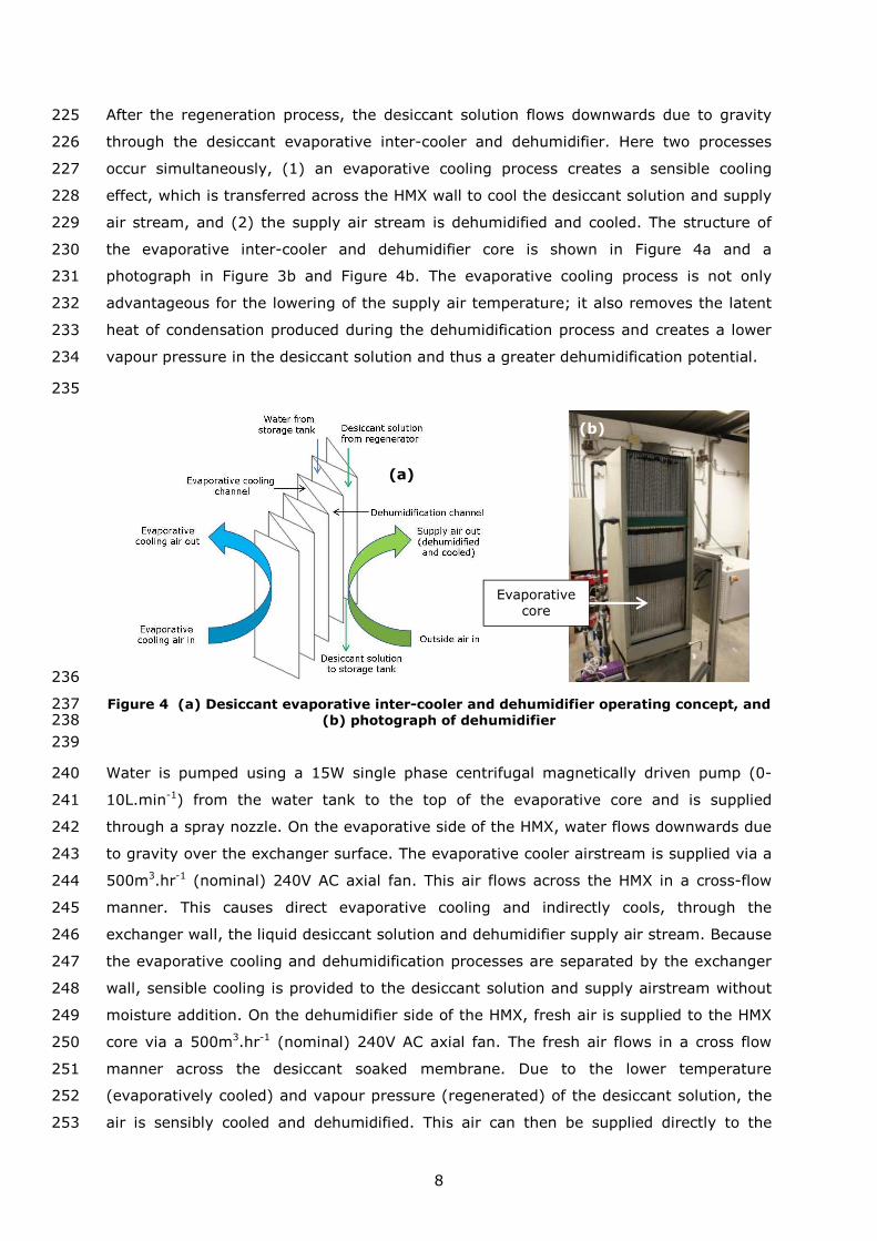
After the regeneration process, the desiccant solution flows downwards due to gravity225
through the desiccant evaporative inter-cooler and dehumidifier. Here two processes226
occur simultaneously, (1) an evaporative cooling process creates a sensible cooling227
effect, which is transferred across the HMX wall to cool the desiccant solution and supply228
air stream, and (2) the supply air stream is dehumidified and cooled. The structure of229
the evaporative inter-cooler and dehumidifier core is shown in Figure 4a and a230
photograph in Figure 3b and Figure 4b. The evaporative cooling process is not only231
advantageous for the lowering of the supply air temperature; it also removes the latent232
heat of condensation produced during the dehumidification process and creates a lower233
vapour pressure in the desiccant solution and thus a greater dehumidification potential.234
235
236
Figure 4 (a) Desiccant evaporative inter-cooler and dehumidifier operating concept, and237(b) photograph of dehumidifier238
239
Water is pumped using a 15W single phase centrifugal magnetically driven pump (0-240
10L.min-1) from the water tank to the top of the evaporative core and is supplied241
through a spray nozzle. On the evaporative side of the HMX, water flows downwards due242
to gravity over the exchanger surface. The evaporative cooler airstream is supplied via a243
500m3.hr-1 (nominal) 240V AC axial fan. This air flows across the HMX in a cross-flow244
manner. This causes direct evaporative cooling and indirectly cools, through the245
exchanger wall, the liquid desiccant solution and dehumidifier supply air stream. Because246
the evaporative cooling and dehumidification processes are separated by the exchanger247
wall, sensible cooling is provided to the desiccant solution and supply airstream without248
moisture addition. On the dehumidifier side of the HMX, fresh air is supplied to the HMX249
core via a 500m3.hr-1 (nominal) 240V AC axial fan. The fresh air flows in a cross flow250
manner across the desiccant soaked membrane. Due to the lower temperature251
(evaporatively cooled) and vapour pressure (regenerated) of the desiccant solution, the252
air is sensibly cooled and dehumidified. This air can then be supplied directly to the253
Evaporativecore
(a)
(b)
Page 9
9
room, or can be passed through another evaporative cooling process to lower its254
temperature further. The warm and weak desiccant solution then flows back to the255
desiccant tank to begin the process again. The water used in the evaporative inter-cooler256
flows back to the separate tank.257
258
Many of the liquid desiccant systems reported in the literature directly heat and cool the259
desiccant solution prior to the regeneration and dehumidification processes. However, in260
the IDCS because all desiccant flow is contained within one complete HMX the desiccant261
solution cannot be extracted for prior heating and cooling, thus heating of the262
regenerator air stream and the inclusion of an evaporative inter-cooler are required.263
264
2.1 Instrumentation265
All fans on the IDCS are equipped with Vent Axia infinitely variable fan speed controllers266
to enable control of the volumetric air flow through the HMX cores. The air inlet and267
outlet of the regenerator, dehumidifier and evaporative HMX cores are fitted with268
125mm galvanised steel spiral tube ducting. The inlet and outlet air flows are269
instrumented with Vaisalia HMP110 humidity and temperature probes. The probes are270
mounted within the spiral tube ducting using special flanges. The humidity and271
temperature probes are factory calibrated. Air velocity through the regenerator,272
dehumidifier and evaporative inter-cooler cores are measured using an RS AM4204 hot273
wire anemometer at the air ducting outlets. The hot wire anemometer is factory274
calibrated. Air velocity measurements are recorded at five points across the air duct, and275
the average taken. The air velocity measurements are also validated against a TSI276
LCA501 rotating vane anemometer.277
278
The desiccant and water pipes connecting the tank to the HMX core have been equipped279
with ball valves (V1 and V2 in Figure 2) so that the desiccant or water volumetric flow280
rate may be set to a desired value. A valve has also been placed on the hot water circuit281
(V3) to control the hot water flow to the regenerator. All water and desiccant solution282
flows have been instrumented with sheathed K-Type thermocouples (Nickel283
Chromium/Nickel Aluminium). Thermocouples have been placed at the inlet to the284
desiccant side (T2) and water side (T3) of the HMX core. Thermocouples have also been285
placed at the hot water inlet (T4) and outlet (T5) to the regenerator liquid to air heat286
exchanger.287
288
Page 10
10
The desiccant solution and water volumetric flow is measured using a 0.2 to 2L.min-1289
Parker Liquid Flow Indicator. These are placed on the pipe connecting the tank to the290
HMX core (F1 on desiccant side, and F2 on water side). The flow meters used are291
calibrated for water at 20°C according to density and viscosity. Thus, for the water flows292
used in the system, no correction is required. For the desiccant solution flow a correction293
factor is required to equate the volumetric flow shown on the flow meter to the actual294
desiccant flow. This correction correlation is shown in Equation 1 [19].295
296
=௦ݒ ୵ݒ ඨ൫ ୪୭ୟ୲− ୪୭ୟ୲
ᇱ ୵ߩୱ୭୪൯ߩ
൫ ୪୭ୟ୲− ୪୭ୟ୲ᇱ ୱ୭୪ߩ୵൯ߩ
1297
298
vsol and vw is the volumetric flow in L.min-1 of the desiccant solution and water299
respectively. For the flow meters used the float weight,� ୪୭ୟ୲= 2.1 × 10ଷ and the float300
volume ′୪୭ୟ୲= 0.25 × 10 ଷ.301
302
The hot water cylinder is equipped with an RS 1–15L.min-1 piston flow meter (F3),303
designed for flow temperatures of up to 60°C. All desiccant solution and water flows on304
the IDCS are equipped with 20mm PVC-U plastic pipe, with plastic fittings. The hot water305
cylinder is piped with insulated 22mm copper pipe and copper fittings. Flexible PVC hot306
water hose is used to connect the hot water cylinder to the regenerator liquid to air heat307
exchanger.308
309
For the accurate evaluation of the desiccant system, the working concentration of the310
desiccant solution needs to be determined. Using a correlation based on the work of311
Melinder [20] the desiccant solution concentration is determined from the solution312
density (ρsol) and temperature (Tsol). In the experimental work the density of the313
desiccant solution is measured using a differential pressure density meter with314
temperature compensation. The meter has been designed to work in the density range315
of the CHKO2 solution (1400 to 1550kg.m-3) and has been calibrated with water. The316
measurement prongs of the differential pressure density meter are placed in the317
desiccant solution tank and held until a steady-state reading is achieved. The318
temperature of the solution is measured using the K-Type thermocouple at the tank319
outlet. The concentration is then calculated using the correlation presented in Equation320
2.321
322
Page 11
11
௦= −253.147703 + 0.0443853996�௦+ 0.000163666247�௦ଶ + ௦ߩ�0.331709855
− ௦ߩ�0.0000793702671ଶ
2323
324
The electrical consumption of fans and pumps are measured using a Brennenstuhl325
PM230 electricity monitor. This is essential for the COPel calculations. At full load the326
desiccant system parasitic electrical load is measured at 400W. A DataTaker DT500327
datalogger is used to record the data from the sensors every ten seconds.328
329
Further details of the measuring equipment used and their associated accuracy are listed330
in Table 1.331
332
Table 1 Instrumentation equipment and associated accuracy333
Measurementdevice
Measurementsubject
Measurementrange
Measurementaccuracy
HMP110 relativehumidity and
temperature probe
Air relative humidityand temperature
0 to 90% RH
0 to 40°C
RHa = ± 1.7% RH
Ta = ± 0.2°C
RS AM4204 hotwire anemometer
Air velocity 0 to 20 m.s-1 ua = ± 5% of reading
K-Typethermocouple
probe
Desiccant solution andwater temperature
0 to 1100°C Tsol / Twater = ± 2.2°C
Parker Liquid FlowIndicator
Desiccant solution andwater volumetric flow
0.2 to 2L.min-1 vsol / vwater = ± 2% ofreading
Desiccant solutiondensity meter
Desiccant solutiondensity
1400–1550kg.m-3 ρsol = ± 10 kg.m-3
BrennenstuhlPM230 electricity
monitor
IDCS electrical powerusage
Up to 16 AmpsWIDCS = ± 3 % of
reading
334
2.2 Uncertainty analysis335
Uncertainty analysis provides a measure of the error associated with a calculated value.336
Using the propagation of error formula [21] the absolute uncertainty of a calculated337
value can be calculated. The maximum relative uncertainty values for the dehumidifier,338
regenerator and complete system performance studies are presented in their respective339
experimental results section. Absolute uncertainty values for six sample dehumidifier,340
regenerator and system performance studies are shown in Table 4 - Table 6 respectively.341
It has been identified that the largest source of error comes from the relative humidity342
measurement which is fundamental to all calculations. The K-Type thermocouples are343
also a large source or error and fundamental to the COP calculations.344
345
Page 12
12
2.3 Experimental method346
The IDCS is installed at The University of Nottingham’s Marmont Laboratory. This is to347
facilitate evaluation under varying environmental and operating conditions in controlled348
laboratory conditions. There are three main components to the laboratory experimental349
set-up shown in Figure 5: (1) the novel IDCS, (2) hot water cylinder and (3)350
environmental chamber. Table 2 provides IDCS air flow identification.351
352
353
Figure 5 IDCS laboratory setup with labelled air flows354
355
Table 2 IDCS air flow identification356
Air flow ID Air flow description Air flow ID Air flow description
A Regenerator HMX inlet D Dehumidifier HMX outlet
B Regenerator HMX outlet E Evaporative cooler inlet
C Dehumidifier HMX inlet F Evaporative cooler outlet
357
The use of the environmental chamber facilitates: (a) a high level of control and provides358
consistent inlet air conditions to the IDCS throughout all tests, and (b) simulation of359
different climates other than the UK; specifically those that favour the use of liquid360
desiccant air conditioning i.e. high humidity. The environmental chamber can create air361
conditions from 0 to 40°C and 10 to 80% relative humidity. The dehumidifier (supply) air362
stream is connected to the environmental chamber by the way of a plenum box.363
However, the regenerator and evaporative inter-cooler air streams use the air from the364
laboratory environment. This is because the complete IDCS could not fit in the365
environmental chamber, and the air flow requirements of the entire IDCS were too high366
to duct all air flows from the chamber to the IDCS. The desiccant evaporative inter-367
Desiccant/water tank
A
B
C
DE
F
IDCS
Hot watercylinder
Plenum box
Environmentalchamber
connection
Page 13
13
cooler will perform better with laboratory (room) air as opposed to environment chamber368
(outside) air as it is drier and thus represents a greater evaporative potential. Similarly,369
the regenerator will perform better with lower humidity laboratory air because it370
possesses a lower vapour pressure. Therefore using laboratory (room) air for the371
evaporative and regeneration processes will improve system performance. All outlet air372
flows are to the laboratory environment.373
374
At the beginning of a test, the temperature and relative humidity of the environmental375
chamber are set. Depending on the requirements it can take up to one hour to achieve376
stable and homogenous air conditions inside. The temperature and relative humidity377
shown on the chambers display panel is cross checked against the Vaisalia HMP110378
humidity and temperature probe at the IDCS dehumidifier inlet and an RS 1365379
handheld humidity-temperature meter within the chamber. Once the desired air380
conditions are achieved, and depending on the test variable under investigation, the381
IDCS operation is set accordingly and run at that condition.382
383
For desiccant solution regeneration, a vented 120 litre hot water cylinder with a 3kW384
electrical immersion heater is used as the thermal input. Before the start of a test the385
hot water tank heater and circulation pump (H/P) are switched on. A by-pass loop is386
used to circulate the water around the tank until it reaches the desired temperature for387
the particular test. A control valve (V3) on the flow pipe is used to provide the desired388
hot water flow to the IDCS. The tank thermostat is set according to the required flow389
temperature. The flow temperature from the tank is checked at regular intervals.390
391
The desiccant solution concentration in the tank is recorded at the start, middle and end392
of each separate test, and the result recorded. The air velocity is measured at each duct393
outlet and recorded at the beginning of each test, and the result recorded. Multiplication394
of the average air velocity by the air duct area provides the volumetric air flow through395
the HMX cores. The desiccant solution and water volumetric flows are measured at the396
start of a test, and the flow indictors checked periodically throughout a test. Depending397
on the test variable being investigated, tests last for 30-60 minutes or until steady-state398
outlet air conditions are achieved for extended periods (30 minutes or more). Data is399
recorded every ten seconds in this period. Only steady-state data is used in the400
performance evaluation. Testing of the dehumidifier and regenerator components are401
carried out con-currently. This is due to the operational nature of the combined IDCS.402
For each variable investigated there were a minimum of three individual tests conducted.403
The results presented are the average of each of these tests.404
Page 14
14
2.3.1 Performance evaluation metrics405
The performance of the dehumidifier is evaluated on the basis of moisture removal rate,406
change in absolute humidity of air across the dehumidifier, latent heat transfer407
(dehumidifier) effectiveness and cooling output.408
409
The dehumidifier moisture removal rate (MRR) in g.s-1 is shown in Equation 3.410
411
MRR = ሶ,ௗ൫ ,,ௗ − ,௨௧,ௗ൯
3412
413
ሶ,ௗ is the mass flow of rate air passing through the dehumidifier HMX core in kg.s-1.414
ωa,in,deh and ωa,out,deh are the dehumidifier’s respective inlet and outlet air absolute415
humidity in kgvapour/kgdryair.416
417
The change in the absolute humidity (kgvapour/kgdryair) of air across the dehumidifier is418
shown in Equation 4.419
420
∆ௗ = ,,ௗ − ,௨௧,ௗ
4421
422
The latent heat transfer (dehumidifier) effectiveness, shown in Equation 5, is the ratio of423
actual moisture transferred to the maximum moisture transfer.424
425
ߟ =,,ௗ − ,௨௧,ௗ
,,ௗ − ,ௗ
5426
427
ωeq is the equivalent moisture content in kgvapour/kgdryair of the desiccant solution at the428
inlet condition, and is a function of its concentration and temperature as shown in429
Equation 6.430
431
= 0.622ቆ,௦(௦ ௦)
௧ − ,௦(௦ ௦)ቇ
6432
433
psol is the vapour pressure in Pa of the desiccant solution at a specified concentration and434
temperature. patm is atmospheric pressure and is equal to 101325Pa. Xsol is the desiccant435
Page 15
15
solution mass concentration, determined using Equation 2. Tsol is the solution436
temperature in °C.437
438
The dehumidifier cooling output in W is shown in Equation 7:439
440
= ,ௗሶ ൫ℎ,,ௗ − ℎ,௨௧,ௗ൯
7441
442
ha,in,deh and ha,out,deh are the respective inlet and outlet specific enthalpies of the air443
entering and leaving the dehumidifier HMX core in J.kg-1. Air enthalpy is a function of444
both temperature and absolute humidity. Therefore air cooling means lowering445
temperature and / or absolute humidity.446
447
The performance of the regenerator is evaluated on the basis of: moisture addition rate448
and regenerator thermal input.449
450
The regenerator moisture addition rate (MAR) in g.s-1 is shown in Equation 8.451
452
MAR = ሶ,൫ ,௨௧, − ,,൯
8453
454
ሶ, is the mass flow rate of air passing through the regenerator HMX in kg.s-1. ωa,out,reg455
and ωa,in,reg are the regenerator’s respective inlet and outlet air absolute humidity in456
kgvapour/kgdryair.457
458
The regenerator thermal input, in W is determined using Equation 9.459
460
= ሶ௪ , ,௪ ,൫ ௪ ,୪୭୵ − ௪ ,୰ ୲୳୰୬൯
9461
462
ݓ ݎ, and ݓ, ݎ, are the respective mass flow rate in kg.s-1 and specific heat capacity in463
J.kg-1.K of the water in the regenerator heating circuit. Tw,flow and Tw,return are the464
respective heating circuit flow and return water temperatures in °C.465
466
Overall IDCS performance is evaluated using COPth and COPel. These are defined in467
Equations 10 and 11 respectively.468
Page 16
16
COP௧ =
10469
470
COP=
௨௫,ௗ௦
11471
472
,ݔݑ ݏ is the IDCS electrical requirement (fans and pumps). Depending on the test473
conditions this ranged from 370W – 400W. The thermophysical properties of the humid474
air are determined from in-built functions in Engineering Equation Solver. The475
thermophysical properties of the desiccant solution are determined from linear476
regression curve fits to published data [20, 22].477
478
3 Results and analysis479
This section presents the results and analysis from the dehumidifier, regenerator and480
complete IDCS experimental evaluation. Due to the combined nature of the IDCS the481
desiccant solution flow in the regenerator HMX has to equal that in the dehumidifier482
HMX. Due to the combined and integrated nature of the system measurement of the483
desiccant solution properties between the regenerator and dehumidifier is not possible.484
Unless otherwise varied, Table 3 provides the operating values used in the experimental485
evaluation of the dehumidifier, regenerator and complete IDCS.486
487
Table 3 Operating values used in the evaluation of the IDCS488
Variable Dehumidifier Inter-cooler Regenerator
Desiccant /water flow (L.min-1) 1.5 1.5 1.5
Desiccant temperature (°C) 23 - 26 --- ---
Water temperature (°C) --- 22 - 25 ---
Solution mass concentration (-) 0.65 – 0.7 --- 0.65 – 0.7
Volumetric air flow (m3.hr-1) 243 269 243
Inlet air temperature (°C) 30 22–26 22–26
Inlet air relative humidity (%) 60 38-66 38-66
489
Throughout all tests a desiccant solution volumetric flow of 1.5L.min-1 was used. It was490
found through experimental evaluation that a volumetric flow above 1.5L.min-1 resulted491
in desiccant solution entrainment in the supply airstream, and below 1.5L.min-1 leads to492
insufficient wetting of the membrane surface.493
Page 17
17
3.1 IDCS dehumidifier component analysis494
The role of the dehumidifier is to cool a supply air stream through the lowering of its495
enthalpy. Enthalpy reduction is achieved primarily through the removal of moisture from496
the air stream to a liquid desiccant solution. Depending on the desiccant solution497
temperature, a reduction in the supply air temperate may also occur. The IDCS498
dehumidifier component evaluation has assessed the impact of inlet air temperature,499
inlet air relative humidity and volumetric air flow on dehumidifier performance. Table 4500
presents the results for six sample dehumidifier tests along with their associated501
absolute uncertainty.502
503
3.1.1 IDCS dehumidifier inlet air condition effect504
The IDCS dehumidifier performance has been evaluated over a 50-70% relative humidity505
range at a 30 and 35°C inlet air temperature. The data presented in Figure 6 shows that506
dehumidifier performance improves with increasing inlet air temperature and relative507
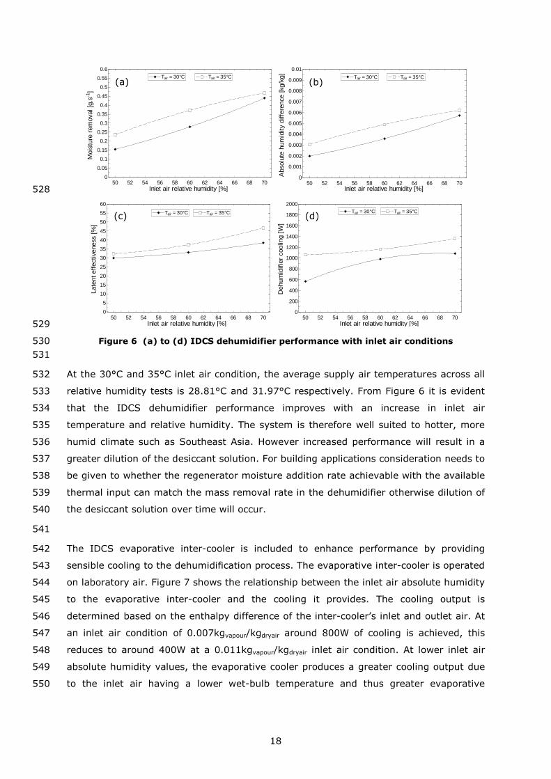
humidity. Figure 6a shows that over the investigated relative humidity range the508
moisture removal rate from the supply airstream increases from 0.1541 to 0.4395g.s-1509
for the 30°C inlet air condition and 0.2354 to 0.4682g.s-1 for the 35°C inlet air condition.510
As the relative humidity and temperature of the inlet air increases, its vapour pressure511
increases, and thus a greater vapour pressure difference between the humid air and512
desiccant solution exists, driving greater mass transfer. Figure 6b shows that over the513
investigated relative humidity range the absolute humidity difference of the supply air514
stream increases, i.e. more dehumidification occurs, from 0.001988 to515
0.005728kgvapour/kgdryair for the 30°C inlet air condition, and from 0.003073 to516
0.0062kgvapour/kgdryair for the 35°C inlet air condition. Figure 6c shows that over the517
investigated relative humidity range the latent (dehumidifier) effectiveness increases518
from 29.91 to 38.39% for the 30°C inlet air condition, and from 32.32 to 46.78% for the519
35°C inlet air condition. Figure 6d shows that over the investigated relative humidity520
range the cooling output from the dehumidifier increases as the inlet air relative521
humidity and temperature increases. The dehumidifier cooling ranges from 570W to522
1084W at an inlet temperature of 30°C, and from 1059W to 1362W at an inlet523
temperature of 35°C. The increase in cooling output with air relative humidity and524
temperature is due to greater moisture removal rate and thus greater latent cooling,525
plus a greater temperature difference between the air and desiccant solution leading to526
increased sensible cooling.527
Page 18
18
528
529
Figure 6 (a) to (d) IDCS dehumidifier performance with inlet air conditions530
531
At the 30°C and 35°C inlet air condition, the average supply air temperatures across all532
relative humidity tests is 28.81°C and 31.97°C respectively. From Figure 6 it is evident533
that the IDCS dehumidifier performance improves with an increase in inlet air534
temperature and relative humidity. The system is therefore well suited to hotter, more535
humid climate such as Southeast Asia. However increased performance will result in a536
greater dilution of the desiccant solution. For building applications consideration needs to537
be given to whether the regenerator moisture addition rate achievable with the available538
thermal input can match the mass removal rate in the dehumidifier otherwise dilution of539
the desiccant solution over time will occur.540
541
The IDCS evaporative inter-cooler is included to enhance performance by providing542
sensible cooling to the dehumidification process. The evaporative inter-cooler is operated543
on laboratory air. Figure 7 shows the relationship between the inlet air absolute humidity544
to the evaporative inter-cooler and the cooling it provides. The cooling output is545
determined based on the enthalpy difference of the inter-cooler’s inlet and outlet air. At546
an inlet air condition of 0.007kgvapour/kgdryair around 800W of cooling is achieved, this547
reduces to around 400W at a 0.011kgvapour/kgdryair inlet air condition. At lower inlet air548
absolute humidity values, the evaporative cooler produces a greater cooling output due549
to the inlet air having a lower wet-bulb temperature and thus greater evaporative550
50 52 54 56 58 60 62 64 66 68 700
0.05
0.1
0.15
0.2
0.25
0.3
0.35
0.4
0.45
0.5
0.55
0.6
Inlet air relative humidity [%]
Mois
ture
rem
ova
l[g
.s-1
]
Tair = 30°C Tair = 35°C
50 52 54 56 58 60 62 64 66 68 700
0.001
0.002
0.003
0.004
0.005
0.006
0.007
0.008
0.009
0.01
Tair = 30°C
Inlet air relative humidity [%]
Abso
lute
hum
idity
diffe
rence
[kg/k
g]
Tair = 35°C
50 52 54 56 58 60 62 64 66 68 700
5
10
15
20
25
30
35
40
45
50
55
60
Late
nt
eff
ect
iveness
[%]
Tair = 35°C
Inlet air relative humidity [%]
Tair = 30°C
50 52 54 56 58 60 62 64 66 68 700
200
400
600
800
1000
1200
1400
1600
1800
2000
Dehum
idifie
rco
olin
g[W
]
Tair = 30°C
Inlet air relative humidity [%]
Tair = 35°C
(a) (b)
(c) (d)
Page 19
19
potential. As a result, in a building application it is recommended to operate the551
evaporative inter-cooler on drier room air, as opposed to fresh outside (humid) air.552
553
554
Figure 7 IDCS evaporative-inter cooler output with inlet air absolute humidity555
556
3.1.2 IDCS dehumidifier volumetric air flow effect557
Figure 8 shows the impact inlet air volumetric flow has on dehumidifier performance at a558
set inlet condition of 30°C and 60% relative humidity. Figure 8a shows the moisture559
removal rate increases with volumetric air flow, from 0.2058g.s-1 at 124m3.hr-1 (fan560
setting 1) to a maximum of 0.2978g.s-1 at 243m3.hr-1 (fan setting 3). There is little561
difference (<0.0116g.s-1) between the moisture removal rate achieved between562
217m3.hr-1 (fan setting 2) and 243m3.hr-1 (fan setting 3). Figure 8b shows that as the563
dehumidifier air volumetric flow increases the change in absolute humidity of the air564
across the dehumidifier reduces from 0.005146kgvapour/kgdryair at 124m3.hr-1 to565
0.003594kgvapour/kgdryair at 243m3.hr-1. As volumetric air flow increases a greater mass of566
air is passed through the dehumidifier and thus the capacity of the dehumidifier to567
reduce the air absolute humidity reduces. This relationship is in conflict with the568
moisture removal rate shown in Figure 8a. This is because moisture removal rate is a569
function of air mass flow rate. Figure 8c shows that as the dehumidifier air volumetric570
flow increases the latent (dehumidifier) effectiveness reduces from 68.52% at 124m3.hr-571
1 to 37.35% at 243m3.hr-1. Figure 8d shows the dehumidifier cooling output increases as572
the volumetric air flow increases from a minimum of 613W at 124m3.hr-1 to 1065W at573
243m3.hr-1. This is primarily due to a larger volume of air being conditioned.574
575
576
0.007 0.008 0.009 0.01 0.0110
200
400
600
800
1000
Eva
pora
tive
coolin
g[W
]
Qevap
Absolute humidity [kgvapour/kgdryair]
Poly fit Qevap r2
= 55.4%
Page 20
20
577
578
Figure 8 (a) to (d) IDCS dehumidifier performance with inlet air volumetric flow579
580
The selection of an appropriate volumetric air flow in the dehumidifier is dependent upon581
the application and the desired supply air condition. Across all dehumidifier tests the582
maximum calculated relative uncertainties in the dehumidifier MRR, Δω, ηL and 583
were ±15.98%, ±15.1%, ±12.47%, and ±15.04% respectively.584
585
3.1.3 IDCS dehumidifier component analysis conclusions586
Over the investigated environmental conditions the dehumidifier performs well with a587
CHKO2 solution at a 0.65 - 0.7 solution mass concentration. Dehumidifier moisture588
removal rates and cooling output increase with inlet air temperature and relative589
humidity in the range of 0.1541 to 0.4682g.s-1 and 570W to 1362W respectively. The590
dehumidifier effectiveness values range from 30 - 47%, typical of a membrane based591
HMX. Volumetric air flow has little impact on moisture removal but a marked impact on592
absolute humidity difference across the dehumidifier, latent effectiveness and593
dehumidifier cooling output. The evaporative inter-cooler provides between 400 and594
800W of cooling to the dehumidifier. The performance of the evaporative-inter cooler595
performance is strongly linked to the inlet air absolute humidity. Thus, in a building596
application it is beneficial to operate the evaporative inter-cooler on drier return room597
air.598
120 140 160 180 200 220 2400
0.05
0.1
0.15
0.2
0.25
0.3
0.35
0.4
Volumetric air flow [m3.hr-1]
Mois
ture
rem
ova
l[g
.s-1
]
30°C 60% RH
120 140 160 180 200 220 2400
0.001
0.002
0.003
0.004
0.005
0.006
0.007
0.008
30°C 60% RH
Abso
lute
hum
idity
diffe
rence
[kg/k
g]
Volumetric air flow [m3.hr-1]
120 140 160 180 200 220 2400
10
20
30
40
50
60
70
80
90
100
30°C 60% RH
Late
nt
eff
ect
iveness
[%]
Volumetric air flow [m3.hr-1]120 140 160 180 200 220 240
0
200
400
600
800
1000
1200
1400
Dehum
idifie
rco
olin
g[W
]
30°C 60% RH
Volumetric air flow [m3.hr-1]
(a) (b)
(c) (d)
Page 21
21
3.2 IDCS regenerator component analysis599
The aim of the regeneration process is to remove the water vapour gained by the600
desiccant solution during the dehumidification process. The moisture removal rate from601
the dehumidifier air stream to the desiccant solution should equal the moisture addition602
rate from the desiccant solution to the regeneration air stream and thus the complete603
system can run continuously. During regenerator evaluation a water flow temperature of604
60°C and water volumetric flow in the heating circuit of 2L.min-1 was used. The IDCS605
regenerator component evaluation has assessed the impact of inlet air absolute606
humidity, volumetric air flow and volumetric water flow in the heating circuit on607
regenerator performance. Table 5 presents the results for six sample regenerator tests608
(same sample as dehumidifier), along with their associated absolute uncertainty.609
610
Figure 9a shows the impact inlet air absolute humidity to the regenerator has on611
moisture addition rate. The inlet air temperature to the regenerator ranges from 22 -612
26°C and the absolute humidity ranges from 0.00708 to 0.01197kgvapour/kgdryair. The613
moisture addition rate ranges from a minimum of 0.07715g.s-1 to a maximum of614
0.2229g.s-1. Mass transfer is driven by a vapour pressure difference between the615
desiccant solution and the regenerator airstream. As the absolute humidity of the616
regenerator inlet airstream increases so does its vapour pressure, resulting in a smaller617
moisture addition rate.618
619
620
Figure 9 IDCS regenerator performance with (a) inlet air absolute humidity, and (b)621volumetric air flow622
623
Figure 9b shows the variation of moisture addition rate from the desiccant solution to the624
regenerator airstream as a function of regenerator volumetric air flow. The novel IDCS625
integrates three components; regenerator, dehumidifier and evaporative inter-cooler into626
one HMX core. As a result, the operation of each component has an impact on the627
others. During volumetric air flow evaluation, the regenerator was operated628
0.007 0.008 0.009 0.01 0.0110
0.05
0.1
0.15
0.2
0.25
0.3
Absolute humidity [kgvapour/kgdryair]
Mois
ture
additio
n[g
.s-1
]
MAR Poly fit MAR r2 = 90.2%
100 120 140 160 180 200 2200
0.02
0.04
0.06
0.08
0.1
Volumetric air flow [m3.hr-1]
Mois
ture
additio
n[g
.s-1
]
(a) (b)
Page 22
22
independently i.e. no dehumidifier or evaporative cooler and as a result the regenerator629
volumetric air flow shown in Figure 9b is lower than that observed during simultaneous630
dehumidifier and regenerator operation. The regenerator volumetric air flow rate is631
increased from 106m3.hr-1 to 212m3.hr-1. It is evident that the volumetric air flow has632
little impact on the moisture addition rate, with values ranging between 0.05118 to633
0.05727g.s-1, an increase of 0.00609g.s-1.634
635
Figure 10a shows the variation of the moisture addition rate in the regenerator with636
respect to the volumetric water flow in the regenerator hot water heating circuit over a637
1.5 - 6.5L.min-1 range. It is evident that the volumetric flow of the water has a marginal638
impact on regenerator capacity, with the moisture addition rate ranging from 0.2363g.s-1639
to 0.2619g.s-1, a difference of 0.0256g.s-1640
641
642
Figure 10 (a) to (b) IDCS regenerator performance with heat exchanger volumetric643water flow644
645
Figure 10b shows the regenerator thermal input as a function of volumetric water flow in646
the regenerator liquid to air heat exchanger. The volumetric water flow has a large647
impact on the thermal input to the system. At 1.5L.min-1 the thermal input is 903W at648
6.5L.min-1 the thermal input is 1285W. As highlighted in Figure 10a the volumetric water649
flow has little impact on the moisture addition rate in the regenerator, it is therefore650
optimal to operate the IDCS at a 1.5L.min-1 volumetric water flow in the regenerator hot651
water circuit., having a lower regenerator thermal input but a similar moisture addition652
rate will assist in improving the COPth of the IDCS. This is discussed in more detail in653
Section 3.3. Across all regenerator tests the maximum calculated relative uncertainty in654
the regenerator MAR was ±25.6%.655
656
1 2 3 4 5 6 70
0.05
0.1
0.15
0.2
0.25
0.3
0.35
0.4
Volumetric water flow [L.min-1]
Mois
ture
additio
n[g
.s-1
]
1 2 3 4 5 6 70
250
500
750
1000
1250
1500
1750
Regenera
tor
input
[W]
Volumetric water flow [L.min-1]
(a) (b)
Page 23
23
3.2.1 IDCS regenerator component analysis conclusions657
Regeneration capacity increases with a lower inlet air absolute humidity. As a result it is658
recommended to operate the regenerator on drier return room air in a building659
application. Volumetric air flow and volumetric water flow in the heating circuit has660
marginal impact on regenerator capacity in the IDCS design. However, the volumetric661
water flow does influence the regenerator thermal input and should be minimised. It is662
evident, across the conditions investigated that there is an issue of instantaneous mass663
balance between the dehumidifier and regenerator i.e. the mass of water vapour664
removed from the air in the dehumidifier does not equal the mass removed from the665
desiccant solution in the regenerator. As a result, the complete IDCS cannot run666
continuously because the solution will become weak over time. The mass imbalance667
issue is discussed in more detail in section 3.3.668
669
3.3 Complete IDCS performance analysis670
The performance of the IDCS is evaluated with respect to its COPth and COPel. The COP671
calculations are previously defined in Equations 10 and 11 respectively. An issue672
encountered with the IDCS is that an instantaneous mass balance between the673
dehumidifier and regenerator is not easily achievable. Mass imbalance is primarily due to674
the available surface area for heat and mass exchange in the regenerator being too675
small and an insufficient vapour pressure differential between the air and desiccant676
solution.677
678
In order to regenerate the desiccant solution back to its original condition following the679
dehumidification process, the regenerator needs to operate for extended time periods.680
As a result, a theoretical adjusted thermal COP (COPth,adj) has been proposed in Equation681
12. The COPth,adj is a steady state value that takes into account the requirement of682
extended regenerator operation in order to achieve a system mass balance.683
684
COP୲୦,ୟ ୨=ୡ୭୭୪୧୬
ቀMRRMAR
ቁ୰
12685
686
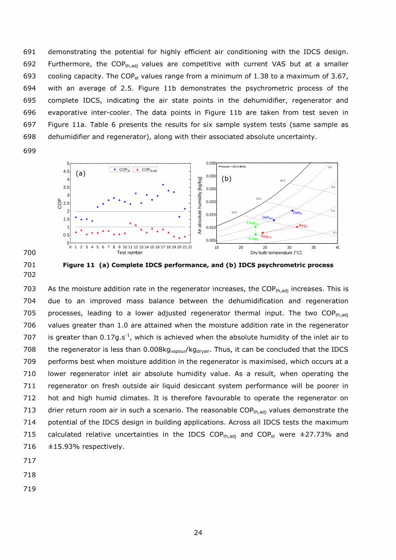
Figure 11a shows the average COPth,adj and COPel for 21 IDCS tests. The black horizontal687
lines at y=1 and y=2 mark the benchmark values for COPth and COPel respectively. The688
COPth,adj values range from a minimum of 0.34 to a maximum of 1.26, with an average689
of 0.72. A COPth above 1.0 is comparable with 5.0 for a VCS driven by grid electricity,690
Page 24
24
demonstrating the potential for highly efficient air conditioning with the IDCS design.691
Furthermore, the COPth,adj values are competitive with current VAS but at a smaller692
cooling capacity. The COPel values range from a minimum of 1.38 to a maximum of 3.67,693
with an average of 2.5. Figure 11b demonstrates the psychrometric process of the694
complete IDCS, indicating the air state points in the dehumidifier, regenerator and695
evaporative inter-cooler. The data points in Figure 11b are taken from test seven in696
Figure 11a. Table 6 presents the results for six sample system tests (same sample as697
dehumidifier and regenerator), along with their associated absolute uncertainty.698
699
700
Figure 11 (a) Complete IDCS performance, and (b) IDCS psychrometric process701
702
As the moisture addition rate in the regenerator increases, the COPth,adj increases. This is703
due to an improved mass balance between the dehumidification and regeneration704
processes, leading to a lower adjusted regenerator thermal input. The two COPth,adj705
values greater than 1.0 are attained when the moisture addition rate in the regenerator706
is greater than 0.17g.s-1, which is achieved when the absolute humidity of the inlet air to707
the regenerator is less than 0.008kgvapour/kgdryair. Thus, it can be concluded that the IDCS708
performs best when moisture addition in the regenerator is maximised, which occurs at a709
lower regenerator inlet air absolute humidity value. As a result, when operating the710
regenerator on fresh outside air liquid desiccant system performance will be poorer in711
hot and high humid climates. It is therefore favourable to operate the regenerator on712
drier return room air in such a scenario. The reasonable COPth,adj values demonstrate the713
potential of the IDCS design in building applications. Across all IDCS tests the maximum714
calculated relative uncertainties in the IDCS COPth,adj and COPel were ±27.73% and715
±15.93% respectively.716
717
718
719
0 1 2 3 4 5 6 7 8 9 10 11 12 13 14 15 16 17 18 19 20 21 220
0.5
1
1.5
2
2.5
3
3.5
4
4.5
5
Test number
CO
P
COPel COPth,adj
15 20 25 30 35 40
0.005
0.010
0.015
0.020
0.025
0.030
0.035Pressure = 101.3 [kPa]
20°C
25°C
30°C
0.4
0.6
0.8
Dehin
Dehout
Regin
RegoutEvapin
Evapout
0.2
Dry bulb temperature [°C]
Air
ab
so
lute
hum
idity
[kg
/kg
]
(a)(b)
Page 25
25
Table 4 Samples of dehumidifier performance data and associated uncertainty720
Samplenumber
Ta,in,deh (°C) RHa,in,deh (%) Xsol Tsol,deh (°C) MRR (g.s-1) Δω (kg/kg) ηL (%) Qcooling (W) Ta,out,deh (°C)
1 30.19 ± 0.2 51.37 ± 1.7 0.66 25.25 ± 0.5 0.15 ± 0.052 0.0019 ± 0.00065 30.02 ± 8.50 580 ± 143 27.77 ± 0.2
2 30.71 ± 0.2 60.43 ± 1.7 0.66 25.39 ± 0.5 0.28 ± 0.054 0.0036 ± 0.00068 38.06 ± 5.73 994 ± 153 27.23 ± 0.2
3 30.14 ± 0.2 70.72 ± 1.7 0.67 25.08 ± 0.5 0.42 ± 0.060 0.0055 ± 0.00073 45.36 ± 4.85 1045 ± 162 30.61 ± 0.2
4 36.18 ± 0.2 50.08 ± 1.7 0.66 27.68 ± 0.5 0.26 ± 0.067 0.0034 ± 0.00086 32.27 ± 6.57 1177 ± 188 29.79 ± 0.2
5 35.39 ± 0.2 60.33 ± 1.7 0.67 25.71 ± 0.5 0.36 ± 0.070 0.0047 ± 0.00089 31.91 ± 4.97 1201 ± 193 31.79 ± 0.2
6 34.70 ± 0.2 70.56 ± 1.7 0.67 25.78 ± 0.5 0.45 ± 0.073 0.0060 ± 0.00091 34.14 ± 4.26 1318 ± 198 32.77 ± 0.2
721
Table 5 Samples of regenerator performance data and associated uncertainty722
Samplenumber
Ta,in,reg (°C) RHa,in,reg (%) MAR (g.s-1)
1 25.80 ± 0.2 47.75 ± 1.7 0.11 ± 0.0572 23.49 ± 0.2 44.09 ± 1.7 0.14 ± 0.0493 25.49 ± 0.2 37.95 ± 1.7 0.19 ± 0.0564 23.96 ± 0.2 38.95 ± 1.7 0.20 ± 0.0525 25.23 ± 0.2 44.33 ± 1.7 0.18 ± 0.0556 24.09 ± 0.2 62.74 ± 1.7 0.12 ± 0.056
723
Table 6 Samples of total system performance data and associated uncertainty724
Samplenumber
COPth,adj COPel
1 0.58 ± 0.30 1.48 ± 0.362 0.69 ± 0.25 2.49 ± 0.383 0.53 ± 0.16 2.62 ± 0.404 1.19 ± 0.33 3.01 ± 0.485 0.76 ± 0.24 2.99 ± 0.486 0.41 ± 0.19 3.28 ± 0.49
725
726
Page 26
26
4 Conclusions727
To date, the application of liquid desiccant air conditioning in smaller (domestic) built728
environment applications has been limited. This is primarily due to large system size and729
complexity, issues of desiccant solution leakage and carry-over and equipment730
corrosion. As a result, a novel IDCS has been developed with the aim of overcoming731
these barriers and facilitating the wider use of the technology in building applications.732
The IDCS combines the regenerator, dehumidifier and evaporative inter-cooler into a733
single HMX. The IDCS design reduces overall system size and limits the amount of734
piping, heat exchangers and pumps. A semi permeable micro-porous membrane is used735
to prevent desiccant solution entrainment in the supply air stream.736
737
The paper has presented an evaluation, based on experimental data, of the novel IDCS738
operating with an environmentally friendly CHKO2 desiccant working fluid. Over the739
investigated environmental and operating conditions the dehumidifier performs well with740
the CHKO2 solution. Dehumidification capacity increases with inlet air temperature,741
relative humidity and air volumetric flow. However, a significant conclusion from the742
work presented is that an instantaneous mass balance between the dehumidifier and743
regenerator is challenging under most conditions. Across the variables investigated there744
is a greater instantaneous moisture removal rate in the dehumidifier than moisture745
addition rate in the regenerator. As a result, a theoretical adjusted thermal COP746
(COPth,adj) has been presented which takes into account the requirement of extended747
regenerator operation in order to achieve a mass balance. The IDCS performs best when748
moisture addition in the regenerator is maximised, which occurs at a lower regenerator749
inlet air absolute humidity value. Across all tests performed an average COPth,adj of 0.72750
has been achieved.751
752
This paper has demonstrated that the novel IDCS design and operating concept is viable.753
No previous work has been found in the literature regarding such an integrated design754
and thus the work provides progress to the field of liquid desiccant air conditioning755
technology for building applications. Future work should focus on increasing the756
regenerator to dehumidifier HMX surface area ratio and improving heat transfer rates to757
the regenerator air stream to improve system mass balance.758
759
760
Page 27
27
5 Nomenclature761
CaCl2 = Calcium Chloride762
CHKO2 = Potassium Formate763
COPel = electrical coefficient of performance764
COPth = thermal coefficient of performance765
COPth,adj = adjusted thermal coefficient of performance766
= specific heat capacity (J.kg-1.K)767
h = specific enthalpy of air (J.kg-1)768
HVAC = heating, ventilation and air conditioning769
IDCS = integrated desiccant air conditioning system770
LiBr = Lithium Bromide771
LiCl = Lithium Chloride772
= mass flow rate (kg.s-1)773
MAR = moisture addition rate in the regenerator (g.s-1)774
MRR = moisture removal rate in the dehumidifier (g.s-1)775
patm= atmospheric pressure (101325 Pa)776
psol = vapour pressure of desiccant solution (Pa)777
= dehumidifier cooling output (W)778
ݒ
= evaporative cooler output (W)779
ݎ
= regenerator thermal input (W)780
RH = relative humidity (%)781
T = temperature (°C)782
u = velocity (m.s-1)783
v = volumetric flow (L.min-1)784
V’ = volume (m3)785
VAS = vapour absorption system786
VCS = vapour compression system787
,ݔݑ ݏ = IDCS electrical requirement (W)788
Xsol = desiccant solution mass concentration789
790
791
Page 28
28
Subscripts792
a = air793
w = water794
sol = desiccant solution795
in = inlet796
out = outlet797
eq = equilibrium798
799
Greek letters800
ηL = latent (dehumidifier) effectiveness (%)801
ρ = density (kg.m-3)802
ω = air absolute humidity (kgvapour/kgdryair)803
804
6 Acknowledgements805
The authors would like to acknowledge the support from European Commission under806
the Fuel Cell and Hydrogen Joint Undertaking Initiative (FCH-JU) for the “Durable low807
temperature solid oxide fuel cell Tri-generation system for low carbon buildings” project,808
agreement No. 303454. The authors would also like to thank the EPSRC and CDT in809
Hydrogen, Fuel cells and their Applications for their continued financial and academic810
support.811
812
7 References813
[1] Pérez-Lombard, L., J. Ortiz, and C. Pout, A review on buildings energy814consumption information. Energy and Buildings, 2008. 40(3): p. 394-398.815
[2] Smith, S.T., V.I. Hanby, and C. Harpham, A probabilistic analysis of the future816potential of evaporative cooling systems in a temperate climate. Energy and817Buildings, 2011. 43(2–3): p. 507-516.818
[3] Welch, T., CIBSE Knowledge Series: KS13 - Refrigeration, H. Carwarardine and K.819Butcher, Editors. 2008, CIBSE Publications.820
[4] Ouazia, B., H. Barhoun, K. Haddad, M. Armstrong, R.G. Marchand, and F.821Szadkowski. Desiccant-evaporative cooling system for residential buildings. in82212th Canadian Conference on Building Science and Technology. 2009. Montréal,823Québec: Institute for research in construction.824
[5] Zhang, L.Z., Energy performance of independent air dehumidification systems825with energy recovery measures. Energy, 2006. 31(8–9): p. 1228-1242.826
[6] Srikhirin, P., S. Aphornratana, and S. Chungpaibulpatana, A review of absorption827refrigeration technologies. Renewable and Sustainable Energy Reviews, 2001.8285(4): p. 343-372.829
Page 29
29
[7] Duan, Z., Zhan, Changhong., Zhang, Xingxing., Mustafa, Mahmud., Zhao,830Xudong., Alimohammadisagvand, Behrang., Hasan, Ala, Indirect evaporative831cooling: Past, present and future potentials. Renewable and Sustainable Energy832Reviews, 2012. 16(9): p. 6823-6850.833
[8] Pietruschka, D., U. Eicker, M. Huber, and J. Schumacher, Experimental834performance analysis and modelling of liquid desiccant cooling systems for air835conditioning in residential buildings. International Journal of Refrigeration, 2006.83629(1): p. 110-124.837
[9] Jain, S. and P.K. Bansal, Performance analysis of liquid desiccant dehumidification838systems. International Journal of Refrigeration, 2007. 30(5): p. 861-872.839
[10] Lowenstein, A., Review of Liquid Desiccant Technology for HVAC Applications.840American Society of Heating, Refrigerating and Air-Conditioning Engineers, 2008.84114(6).842
[11] Longo, G.A., Gasparella, A., Experimental and theoretical analysis of heat and843mass transfer in a packed column dehumidifier/regenerator with liquid desiccant.844International Journal of Heat and Mass Transfer, 2005. 48(25–26): p. 5240-8455254.846
[12] Kozubal, W., J. Woods, J. Burch, A. Boranian, and T. Merrigan Desiccant847Enhanced Evaporative Air-Conditioning (DEVap): Evaluation of a New Concept in848Ultra Efficient Air Conditioning. 2011.849
[13] Hassan, H.Z. and A.A. Mohamad, A review on solar cold production through850absorption technology. Renewable and Sustainable Energy Reviews, 2012. 16(7):851p. 5331-5348.852
[14] Halliday, S.P., C.B. Beggs, and P.A. Sleigh, The use of solar desiccant cooling in853the UK: a feasibility study. Applied Thermal Engineering, 2002. 22(12): p. 1327-8541338.855
[15] Gommed, K. and G. Grossman, Experimental investigation of a liquid desiccant856system for solar cooling and dehumidification. Solar Energy, 2007. 81(1): p. 131-857138.858
[16] Fong, K.F., Chow, T. T., Lee, C. K., Lin, Z., Chan, L. S., Comparative study of859different solar cooling systems for buildings in subtropical city. Solar Energy,8602010. 84(2): p. 227-244.861
[17] Beccali, M., P. Finocchiaro, and B. Nocke, Energy performance evaluation of a862demo solar desiccant cooling system with heat recovery for the regeneration of863the adsorption material. Renewable Energy, 2012. 44(0): p. 40-52.864
[18] Jain, S., S. Tripathi, and R.S. Das, Experimental performance of a liquid desiccant865dehumidification system under tropical climates. Energy Conversion and866Management, 2011. 52(6): p. 2461-2466.867
[19] Liu, S., A Novel Heat Recovery/Desiccant Cooling System, in Architecture and868Built Environment. 2008, The University of Nottingham: Nottingham.869
[20] Melinder, A., Thermophysical Properties of Aqueous Solutions Used as Secondary870Working Fluids, in Energy Technology. 2007, KTH Energy and Environmental871Technology: Stockholm.872
[21] Taylor, J.R., An Introduction to Error Analysis: The Study of Uncertainties in873Physical Measurements. Second Edition ed. 1997, Sausalito, California: University874Science Books.875
[22] James, S., A New Working Fluid 'Potassium Formate' for use in Absorption Heat876Pumps, in Architecture and Built Environment. 1998, The University of877Nottingham: Nottingham.878
879