Page 1
HAL Id: hal-00699053https://hal.archives-ouvertes.fr/hal-00699053
Submitted on 19 May 2012
HAL is a multi-disciplinary open accessarchive for the deposit and dissemination of sci-entific research documents, whether they are pub-lished or not. The documents may come fromteaching and research institutions in France orabroad, or from public or private research centers.
L’archive ouverte pluridisciplinaire HAL, estdestinée au dépôt et à la diffusion de documentsscientifiques de niveau recherche, publiés ou non,émanant des établissements d’enseignement et derecherche français ou étrangers, des laboratoirespublics ou privés.
Experimental investigation to optimise a desiccantHVAC system coupled to a small size cogenerator
Giovanni Angrisani, Francesco Minichiello, Carlo Roselli, Maurizio Sasso
To cite this version:Giovanni Angrisani, Francesco Minichiello, Carlo Roselli, Maurizio Sasso. Experimental investiga-tion to optimise a desiccant HVAC system coupled to a small size cogenerator. Applied ThermalEngineering, Elsevier, 2010, 31 (4), pp.506. �10.1016/j.applthermaleng.2010.10.006�. �hal-00699053�
Page 2
Accepted Manuscript
Title: Experimental investigation to optimise a desiccant HVAC system coupled to asmall size cogenerator
Authors: Giovanni Angrisani, Francesco Minichiello, Carlo Roselli, Maurizio Sasso
PII: S1359-4311(10)00433-3
DOI: 10.1016/j.applthermaleng.2010.10.006
Reference: ATE 3264
To appear in: Applied Thermal Engineering
Received Date: 9 February 2010
Revised Date: 7 September 2010
Accepted Date: 10 October 2010
Please cite this article as: G. Angrisani, F. Minichiello, C. Roselli, M. Sasso. Experimental investigationto optimise a desiccant HVAC system coupled to a small size cogenerator, Applied Thermal Engineering(2010), doi: 10.1016/j.applthermaleng.2010.10.006
This is a PDF file of an unedited manuscript that has been accepted for publication. As a service toour customers we are providing this early version of the manuscript. The manuscript will undergocopyediting, typesetting, and review of the resulting proof before it is published in its final form. Pleasenote that during the production process errors may be discovered which could affect the content, and alllegal disclaimers that apply to the journal pertain.
Page 3
1
Experimental investigation to optimise a desiccant HVAC system coupled to a
small size cogenerator
Giovanni Angrisania*, Francesco Minichiellob, Carlo Rosellia, Maurizio Sassoa
aDING, University of Sannio, Piazza Roma 21, 82100 Benevento, Italy
bDETEC, University of Naples Federico II, P.le Tecchio 80, 80125 Naples, Italy
*Corresponding author. Tel.: +39 0824 305576; fax: +39 0824 325246. E-mail addresses:
[email protected] (G. Angrisani), [email protected] (F. Minichiello),
[email protected] (C. Roselli), [email protected] (M. Sasso).
ABSTRACT
In the Mediterranean area, the increasing demand of summer cooling in residential and tertiary sectors is
usually satisfied by electrically-driven units; this often determines electric load peaks and black-outs.
Thus, a wide interest is spreading in small scale natural gas-fired polygeneration systems: a prime mover
drives (mechanically, electrically, thermally) electric generators and/or heat pumps, desiccant wheels,
etc., matching thermal (heating and cooling) and electric end-user requirements.
In this paper, laboratory tests have been considered to experimentally evaluate a small scale
polygeneration system based on a natural gas-fired Micro-CHP and a desiccant-based HVAC system.
Cogenerated thermal power is used for the desiccant wheel regeneration, while electric power for
auxiliaries, chiller and external units. The HVAC system can also interact with electric and thermal
separate “production” systems. The main results of the experimental tests are shown, stating the increase
of the COP of the chiller in desiccant-based HVAC systems. Then the paper identifies the operating
conditions (outdoor and supply air thermal-hygrometric conditions, electric grid efficiency and partial
load operation of the MCHP) which guarantee significant primary energy savings (up to around 30 %)
and CO2 equivalent emission reductions (up to around 40 %) of the polygeneration system compared to
the conventional HVAC system.
Page 4
2
Keywords: decentralized polygeneration, Micro-CCHP, desiccant wheel, hybrid HVAC system,
experimental analysis.
1. Introduction
During last years, great attention was focused on the transition from centralized to decentralized energy
“production” systems (Decentralized or Distributed Generation, DG), to reduce T&D energy losses: a
miniaturization process (“size” effect) is in progress.
A comparison between centralized and distributed power systems is carried out in [1]: small, modern
generators can be more efficient and less costly to operate than large and old generators. This could lead
to conclude that there is no longer an economy of scale in power “generation”, but large modern power
units have higher electric efficiency and lower operating cost than small modern DG units based on the
same technology. Since the “size” effect does not always lead to energy savings and pollutant emission
reductions, there is the need to support the diffusion of on-site small complex energy conversion devices,
Decentralized Polygeneration, DP. A widespread use of DP systems could allow energy, economic and
environmental benefits: the benefits and drawbacks of DP are analysed in [2].
Furthermore, especially in Mediterranean area, there is an increasing demand of summer cooling energy
in domestic sector, usually satisfied by electrically-driven units; this involves electric load peaks and
black-outs. Thus, an increasing interest occurs in small scale polygeneration systems fuelled by natural
gas.
Micro Combined Cooling, Heating and Power (MCCHP, electric power output ≤ 15 kW) systems
represent typical decentralized energy “production” systems, particularly suitable for use in
Mediterranean areas.
In the CCHP systems, the prime mover can be based on different technologies (Stirling, Reciprocating
Internal Combustion - RIC, Fuel Cell, Gas Turbine, etc.). The most mature technology available on the
market, gas-fired RIC engines, allows small installation space, high thermal efficiency, low noise,
vibrations and maintenance and long life service. These engines, coupled to electric generators, can drive
electric heat pumps, thermal heat pumps, Desiccant Wheels - DW, etc., allowing a wide range of
operating conditions to match thermal (heating and cooling) and electric end-user requirements.
Page 5
3
In summer, to supply cooling energy, recovered thermal energy can be used for the regeneration of the
desiccant wheel, as well as for the activation of absorption/adsorption heat pumps, while, in winter,
engine thermal wastes allow to satisfy domestic hot water and heating purposes. Thermal energy input for
desiccant wheel regeneration can also be derived from solar source in Solar Heating and Cooling (SHC)
systems [3-5]. Solar collectors are typically integrated with fossil fuel-based technologies to match the
entire heat demand, SHC-CCHP systems. These systems offer the typical advantages of natural gas-fired
polygeneration systems coupled to a renewable energy source. Despite of these advantages, coupling
solar collectors and a CCHP unit for heating, cooling and electric purposes presents certain critical issues
[6]; furthermore, this energy conversion system (solar thermal collectors, storage systems and CCHP) is
very complex, both in design phase, to optimize the size of each subsystem, and during operation, its
performance being dependent on many variables (energy tariff structure, load profiles, etc.).
Few investigations have been carried out on solid desiccant systems coupled to small scale combined
cooling, heat and power systems, and little attention has been paid on both energy and environmental
performances [7 – 10].
Therefore, this paper experimentally analyses a desiccant-based MCCHP system which includes a hybrid
Air Handling Unit - AHU - (the term hybrid refers to the contemporary presence of a desiccant wheel and
an electric chiller that, in succession, dehumidify and cool the air to be introduced in the conditioned
space). This HVAC system is suitable above all for residential and small commercial users. An energy
and environmental analysis for different operating modes has been carried out.
The system performance has been evaluated as a function of various working conditions (outdoor and
supply air thermal-hygrometric conditions and MCHP partial load operation), in order to establish the
effectiveness of such systems compared to a conventional HVAC system based on separate electric and
thermal “production”. Finally, the influence of the electric grid efficiency to analyse the polygeneration
system in different electricity mix scenarios has been considered, as well as the effect of the regeneration
temperature on the energy savings.
2. Test facility
Page 6
4
At Sannio University, in Benevento (Southern Italy), a desiccant Air Handling Unit coupled to a
cogenerator based on a natural gas-fired reciprocating internal combustion engine, an electric chiller and a
natural gas-fired boiler, has been experimentally analysed. The hybrid HVAC system is based on
dehumidification of outdoor air by a desiccant wheel and subsequent cooling by an electric chiller.
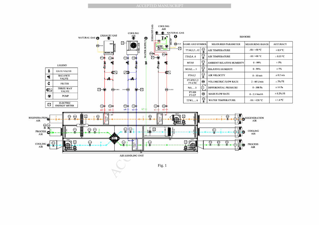
In Fig. 1, the layout of the test facility is shown [10].
Nominal characteristics of the equipment are the following:
• cogenerator: Pel = 6.0 kW (0.200 kW for the cogenerator auxiliary electric loads), Pth = 11.7 kW, ηel =
28.8%, ηth = 56.2 %; the MCHP supplies thermal power for the desiccant wheel regeneration by
recovering heat from the exhaust gas and from the engine. The maximum thermal output is available
for a water flow rate of 33.5 l/min, at a temperature in the range 60 – 65 °C. The actual flow rate
(17.0 l/min) during the tests is lower than the nominal one and consequently the hot water is available
at 72.5 °C. Due to thermal losses in the distribution pipes and to the effectiveness of the air-to-water
heat exchanger, the maximum achievable regeneration air temperature is 65 °C; the MCHP mainly
supplies electric energy for AHU electric loads (fans, pumps, desiccant wheel, etc.), chiller and further
external electric devices (computers, lights, etc.).
• air-cooled water chiller: Pco = 8.50 kW, COP = 3.00;
• boiler: Pth = 24.1 kW, ηb = 90.2 %. The boiler can be either used to supply thermal energy when the
hybrid HVAC is powered by separate “production” systems, or to integrate the thermal power
available from the MCHP. In fact, in hot and humid climates, to reach the desired ωs, the regeneration
air temperature should be consequently increased, so thermal power is supplied also by the boiler,
allowing to reach regeneration temperature of 70°C.
The AHU treats 800 m3/h of air that achieves the summer supply conditions required by the room (Ts =
13-19 °C, ωs = 7-11 g/kg).
There are three outdoor air streams:
Page 7
5
• process air, dehumidified by the desiccant wheel, pre-cooled by the cooling air stream in an air-to-air
cross flow heat exchanger, finally cooled to the supply temperature by a cooling coil interacting with
the chiller;
• DW regeneration air, heated by the heating coil interacting with the MCHP and/or by the heating coil
interacting with the boiler;
• cooling air, cooled by a direct evaporative cooler and then used to pre-cool process air.
The weight of the DW is 50 kg; its dimensions are 700 mm x 700 mm x 440 mm (height x width x
thickness), with a diameter of 700 mm. In reality, the frontal area of the rotor effectively exposed to
process and regeneration airflows is relative to a diameter of about 600 mm, since a circular crown of the
total area is obstructed by the metallic frame in the AHU. The rotor has the following configuration: 60%
of the rotor area is crossed by the process air, while the remaining 40% by the regeneration air. This is
often used when there is low temperature regeneration thermal energy.
In fact, the DW is filled with silica-gel, a desiccant material that can be effectively regenerated at
temperatures as low as 60-70 °C, values obtainable by using the thermal recovery from the MCHP and,
only when necessary, the natural gas boiler. The rotor matrix is composed of alternate layers (smooth and
wavy) of silica-gel sheets and metallic silicate, chemically bound into an inorganic fiber frame.
The so realized “honeycomb” frame has several advantages, such as the maximization of the superficial
contact area, low pressure drops, low weight but high structural durability.
In Fig. 2, the Sankey diagram of the polygeneration system is shown, to highlight the main power flows
and losses (outdoor thermal-hygrometric conditions: To = 33.9 °C, ωo = 10.3 g/kg; regeneration
temperature 65.0 °C). For the global system and for its main subsystems, power inputs and outputs are
reported, also considering electric loads of the MCHP and AHU auxiliaries (including circulation electric
power absorption).
3. Energy and environmental analysis
Page 8
6
The hybrid HVAC system has been experimentally tested in stationary conditions for a length of 30
minutes for each test. The results of the experimental analysis allowed to compare the above described
alternative system, AS, to the following usually adopted conventional air conditioning system, CS.
In the latter, outdoor air is cooled and dehumidified by an electric chiller powered by the electric grid;
then, it is reheated by a natural gas-fired boiler. Auxiliaries and external electric devices are powered by
the electric grid.
According to the European Directive 2004/8/EC, [11, 12], the reference energy efficiencies for both
electric grid and the boiler has been evaluated, with respect to Italy,:
• Electric grid: ηeg = 45.2 %, CO2 equivalent emission = 0.531 kgCO2/kWhel [13];
• Boiler: efficiency = 90 %, CO2 equivalent emission = 0.20 kgCO2/kWhp; natural gas lower heating
value = 9.59 kWh/Nm3.
The comparison is carried out assuming that both AS and CS deliver equal energy (electric and cooling
energy; thermal energy recovered from the MCHP is fully used to DW regeneration). Moreover, the two
systems handle 800 m3/h of process air and operate at the same outdoor and supply thermal-hygrometric
conditions. For example, Fig. 3 shows the energy flows of AS and CS.
The Primary Energy Saving, PES, has been considered for the energy comparison, [14]:
CSp
ASp
CSp
E
E-E=PES (1)
Furthermore, the avoided CO2 equivalent emissions of the alternative system with respect to the
conventional one have been evaluated too.
4. Experimental analysis
The start-up of the experimental test facility (calibration of the measuring systems, design of data
acquisition and monitoring software, etc.) has been initially carried out. A user-friendly graphical
interface records the main parameters, such as: air temperature and relative humidity in the main AHU
sections, inlet and outlet water temperature for heat exchangers, boiler, MCHP and chiller, volumetric
Page 9
7
flow rate (water and natural gas), electric energy and power flows. So, thermal and electrical MCHP
efficiencies, COP of the chiller, PER, etc., have been evaluated too.
After a starting phase [10], during summer 2009, many tests have been carried out, representing a wide
range of outdoor air thermal-hygrometric conditions and different AHU operating modes.
4.1 Comparison between AS and CS
AHUs based on chemical dehumidification have the advantage of reducing cooling energy demand, for
the lack of cooling-based dehumidification, on which the conventional air conditioning systems are
instead based. Furthermore, the refrigeration unit can produce chilled water at higher temperatures,
compared to a chiller that operates in a conventional HVAC system, and consequently it will operate with
higher COP.
For these reasons, attention has been paid to the evaluation of the performance of the electric chiller in the
CS: a detailed model, based on well known simulation codes of inverse machines, allows to evaluate the
performance of the air-cooled water chiller interacting with external secondary fluids, air and water [15,
16]. Both full and part load operating conditions have been considered, in agreement with literature [17].
Many tests have been realized, considering different operating conditions and electric energy quantities
supplied to the final user.
In Fig. 4, the full load COP of the chiller in alternative and conventional HVAC systems is reported as a
function of To and for different ωs values. The COP in the alternative system (“DW”) obviously does not
depend on ωs because the dehumidification is carried out by the desiccant wheel, not by the chiller.
Contrariwise, the COP of the chiller interacting with the cooling/dehumidification coil strongly decreases
on ωs reduction. For many operating conditions, the chiller interacting with the hybrid HVAC system
performs better than the conventional one that has also a “size” (cooling capacity) more than twice. Only
for low outdoor temperature (< 29 °C) and high values of supply air humidity ratio (> 10.8 g/kg) COP of
the chiller interacting with the conventional AHU is greater than the alternative one.
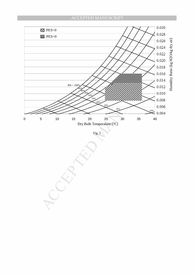
To highlight the influence of outdoor air properties on the energy performances of AS and CS, in Fig. 5
outdoor air thermal-hygrometric conditions that get a positive PES are shown. The hybrid HVAC system
Page 10
8
interacting with the MCHP requires less primary energy than the conventional system for ωo lower than
about 11.5 g/kg and To in the range 25-36 °C. For ωo > 11.5 g/kg, the lower limit of the previous
temperature range increases: for ωo = 13.0 g/kg, AS is preferable only for To> 28 °C. Finally, for ωo >
13.0 g/kg, AS is no more energetically suitable.
In Fig. 6, the PES as a function of ωo and for three different values of To is shown. PES increases when ωo
decreases, reaching a maximum value for ωo = 8.00 g/kg (24 %, 31 % and 35 % for To equal to 25.0 °C,
29.0 °C and 33.5 °C, respectively). PES becomes positive when ωo is lower than a certain value,
depending on outdoor air temperature (11.4 g/kg, 12.6 g/kg and 13.0 g/kg for the three To values,
respectively). Moreover, PES increases with To.
In the range of operating conditions of Fig. 6, the avoided CO2 equivalent emissions show the same trend
as PES, achieving a maximum value of 43%. The avoided emissions go to zero when ωo is in the range
14.5-16 g/kg (depending on To value), while PES goes to zero when ωo is in the range 11.2-13.1 g/kg.
Therefore, the ambient convenience remains in a wider outdoor humidity ratio range compared to the
energy convenience.
As explained above, the electric grid efficiency remains a key factor. In Fig. 7, at constant operating
conditions (Table I), the influence of ηeg on PES is reported. In the base case (ηeg = 45.2 %), PES is about
22 %; then it increases with ηeg reduction.
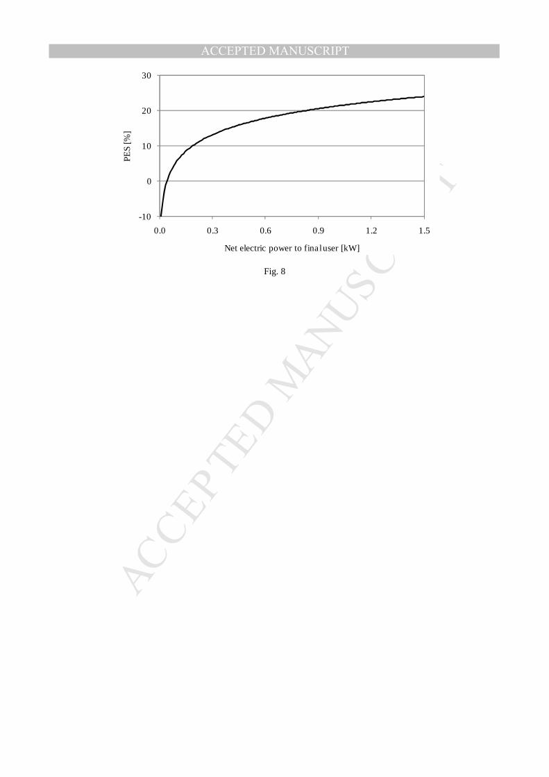
The influence of the partial load operation of the MCHP on the global energy performance has been
analysed too. The net electric power for computers, lights, etc., has been gradually increased up to 1.5 kW
to allow the full load of the cogenerator (for To = 29.5 °C and ωo = 10.2 g/kg, the electric power supplied
by the MCHP to the chiller and to the MCHP and AHU auxiliaries is about 4.5 kW). Fig. 8 shows that
PES increases with the net electric power supplied to the final user, so it is convenient to operate the
MCHP at full load for the maximum number of hours (PES of around 24 %): this, in fact, causes an
increase of electric efficiency of the micro-cogenerator. Also in this case, the reduction of CO2 equivalent
emissions show the same trend as PES; it achieves the maximum value (35%) at full load operation of the
MCHP.
Page 11
9
In a previous paper, the influence of the regeneration temperature on the selected DW performance has
been analyzed, [18]. It has been shown that the dehumidification capability of the wheel, ∆ω, increases
when regeneration temperature rises: with To = 30.5 °C and ωo = 10.7 g/kg, ∆ω varies from 1.0 g/kg to
5.6 g/kg when regeneration temperature increases from 34 to 72 °C.
It is evident that the reduction of process air humidity ratio that the DW realizes, ∆ω, is strictly related to
the room latent load it has to balance. Therefore the regeneration temperature can be used as a control
parameter, in desiccant-based HVAC systems, to dynamically follow the latent load to handle. If, for
example, the latter decreases, the regeneration temperature can be automatically reduced.
If the MCHP continues working at full load, as this is the best operating condition in terms of energy
performance (see Fig. 8), the reduction of the regeneration temperature can be achieved, at constant
regeneration air flow rate (800 m3/h), only by wasting a part of the available thermal power. Therefore the
PES obviously reduces. In fact, in the same outdoor operating conditions as above (To = 30.5 °C and ωo =
10.7 g/kg), it decreases from 30% to -10 % when the regeneration temperature reduces from 65 to 34 °C.
The desiccant-based HVAC system can also be powered by separate “production” of electric and thermal
energy, respectively provided by the electric grid and a natural gas boiler. Considering the above reported
values for the boiler (90%) and the electric grid efficiency (45.2%), the desiccant-based HVAC system
powered by the MCHP (AS) guarantees an average PES of 18% with respect to the same system powered
by separate “production”. Even if the electric energy “production” is based on the Best Available
Technology (BAT, i.e. with natural gas combined cycle power plants, ηeg = 0.58), PES remains positive
(8.2% on average).
The PES values obtained in this work are in good agreement with quite similar polygeneration systems
and operating conditions [7-8].
5. Conclusions
Experimental tests have been carried out in Benevento (Southern Italy) to analyse a hybrid desiccant
HVAC system driven by a MCCHP, in order to evaluate its energy and environmental performances
compared to a conventional system based on an electric chiller.
Page 12
10
The performances of the two systems are strongly influenced by outdoor thermal-hygrometric conditions:
the alternative system can guarantee a Primary Energy Saving when outdoor air humidity ratio is lower
than a certain value (11.5 g/kg) and outdoor air temperature is in the range 25 – 36 °C. Moreover, PES
increases with To and when ωo decreases, reaching a maximum value for ωo = 8.0 g/kg, 24 % for To =
25.0 °C, 31 % for To = 29.0 °C, 35 % for To = 33.5 °C. The avoided CO2 equivalent emissions show the
same trend as PES, achieving a maximum value of 43%.
Obviously, PES decreases when electric grid efficiency increases.
Moreover, the best performance (PES of around 24 %, considering the operating conditions of the
specific test) is obtained when the MCHP works at full load; so a detailed analysis of the electric loads
and a correct sizing of the small-scale cogeneration system have to be carried out to minimize the
operating hours at partial load. Also in this case the reduction of CO2 equivalent emissions show the same
trend as PES; it achieves the maximum value (35%) at full load operation of the MCHP.
With the MCHP working at full load, if the regeneration temperature has to be automatically decreased
for control purposes (to reduce the latent load balanced by the desiccant wheel), the PES decreases until it
becomes negative for very low regeneration temperatures (minus than 42 °C).
Furthermore, the desiccant-based HVAC system powered by the MCHP (AS) guarantees an average PES
of 18% with respect to the same HVAC system powered by separate “production” of electric and thermal
energy. Even if the electric energy “production” is based on the Best Available Technology (BAT, ηeg =
0.58), PES remains positive (8.2% on average).
Further investigations are required as regards economic savings and the introduction of a solar collecting
system in the existing polygeneration plant.
Acknowledgments
This work has been financed by Italian research project PRIN 2007 "Criteria and methodologies for the
optimization of small/medium scale polygeneration systems".
Moreover, this work was developed in a research project promoted by International Energy Agency
(IEA), Annex 54, Integration of Micro-generation and Related Energy Technologies in Buildings.
Page 13
11
Nomenclature
CO2
E
Carbon dioxide equivalent emissions [kg/h]
Energy [kJ]
P Power [kW]
PES Primary Energy Saving [-]
re
RH
Electric energy share provided to the chiller [-]
Relative Humidity [%]
T Temperature [°C]
η Efficiency [-]
ω Air humidity ratio [g/kg]
∆ω Air humidity ratio variation [g/kg]
AHU Air Handling Unit
AS
BAT
CCHP
Alternative System
Best Available Technology
Combined Cooling Heating and Power
CHP Combined Heat and Power
COP Coefficient Of Performance
CS
DG
Conventional System
Decentralized or Distributed Generation
Page 14
12
DP Decentralized or Distributed Polygeneration
DW Desiccant Wheel
HVAC Heating Ventilation and Air Conditioning
MCCHP Micro Combined Cooling Heat and Power
MCHP
PM
RIC
SHC
T&D
Micro Combined Heat and Power
Prime Mover
Reciprocating Internal Combustion
Solar Heating and Cooling
Transmission and Distribution
Subscripts
AHU
b
co
o
eg
Air Handling Unit
boiler
cooling
outdoor air
electric grid
el electric
p
s
th
primary
supply air
thermal
Page 15
13
Superscripts
AS Alternative System
B Boiler
CS Conventional System
CH Chiller
EG Electric Grid
US End User
REFERENCES
[1] H.L. Willis, W.G. Scott, Distributed power generation: planning and evaluation, Marcel Dekker Inc.,
New York, 2000 (ISBN 0-8247- 0336-7)
[2] R. Possidente, C. Roselli, M. Sasso, S. Sibilio, Small scale decentralized polygeneration systems,
Proceedings of ECOS 2009, 22nd International Conference on Efficiency, Cost, Optimization,
Simulation and Environmental Impact of Energy Systems, Foz do Iguaçu, Paraná, Brazil, August 31 –
September 3, 2009
[3] D. Pietruschka, U. Eicker, V. Nanby, Primary energy optimised operation of solar driven desiccant
evaporative cooling systems through innovative control strategies, Proceedings of 3rd Solar Air
Conditioning International Conference, Palermo, Italy, September 31 – October 2, 2009-12-29
[4] Y.J. Dai, D. La, Y. Li, Z.X. Jiang, T.S. Ge, R.Z. Wang, An energy efficient solar driven two-stage
rotary desiccant cooling system: experiment and case study, Proceedings of 3rd Solar Air Conditioning
International Conference, Palermo, Italy, September 31 – October 2, 2009-12-29
[5] M. Beccali, P. Finocchiaro, B. Nocke, Solar desiccant cooling system operating in Palermo (Itay):
results and validation of simulation results, Proceedings of 3rd Solar Air Conditioning International
Conference, Palermo, Italy, September 31 – October 2, 2009-12-29
Page 16
14
[6] A. Napolitano, G. Franchini, G. Nurzia, W. Sparber, Coupling solar collectors and co-generation units
in solar assisted heating and cooling systems, Proceedings of EUROSUN 2008, 1st International
Conference on Heating, Cooling and Buildings, Lisbon, Portugal, October 7-10, 2008
[7] G. Schmitz, W. Casas, Experiences with a small gas engine driven desiccant HVAC-system,
Proceedings of IGRC 2001, 8th International Gas Research Conference, Amsterdam, The Netherlands,
November 5-8, 2001
[8] G. Schmitz, W. Casas, Experiences with a gas driven, desiccant assisted air conditioning system with
geothermal energy for an office building, Energy and Buildings 37 (5) (2005) 493-501
[9] A. Jalalzadeh-Azar Ali, S. Slayzak, R. Judkoff, Performance assessment of a desiccant cooling system
in a CHP application incorporating an IC engine, International Journal of Distributed Energy Resources 1
(2) (2005) 163-184
[10] G. Angrisani, F. Minichiello, C. Roselli, M. Sasso, G.P. Vanoli, Experimental analysis of small scale
polygeneration system based on a natural gas-fired Micro-CHP and a hybrid HVAC system equipped
with a desiccant wheel, Proceedings of ECOS 2009, 22nd International Conference on Efficiency, Cost,
Optimization, Simulation and Environmental Impact of Energy Systems, Foz do Iguaçu, Paraná, Brazil,
August 31 – September 3, 2009
[11] Directive 2004/8/EC of the European Parliament and the Council of 11 February on the promotion of
cogeneration based on a useful heat demand in the internal energy market and amending Directive
92/42/EEC, Official Journal of the European Union, 21.02.2004
[12] Commission Decision of 21st December 2006, establishing harmonised efficiency reference values
for separate production of electricity and heat in application of Directive 2004/8/EC of the European
Parliament and of the Council, Official Journal of the European Union, 06.02.2007
[13] Italian Environmental Ministry, www.minambiente.it
[14] V. Dorer, A. Weber, Methodologies for the Performance Assessment of Residential Cogeneration
Systems, Report of IEA ECBCS Annex 42, 2007
Page 17
15
[15] CoolPack Version 1.46 Copyright © Department of Mechanical Engineering Technical University of
Denmark www.et.dtu.dk/CoolPack, 2000
[16] IMST-ART Version 3.20.02 Instituto de Ingeniería Energética Universidad Politécnica de Valencia,
www.imst-art.com
[17] E. Bettanini, A. Gastaldello, L. Schibuola, Simplified models to simulate part load performances of
air conditioning equipments, Proceedings of IBPSA 2003, 8th International Conference of International
Building Performance Simulation Association, Eindhoven, The Netherlands, August 11-14, 2003
[18] G. Angrisani, F. Minichiello, C. Roselli, M. Sasso, Desiccant HVAC system driven by a micro-CHP:
Experimental analysis, Energy and Buildings 42 (11) (2010) 2028-2035
FIGURE CAPTIONS
Fig. 1 - Layout of the test facility
Fig. 2 - Sankey diagram of the polygeneration system
Fig. 3 - Energy flows of Alternative System and Conventional System
Fig. 4 - COP of the electric chiller in the conventional HVAC system (for different values of supply air
humidity ratio) and in the desiccant-based HVAC system, as a function of the outdoor air temperature
Fig. 5 - Psychrometric chart showing the area where PES is <0 and that where PES is >0
Fig. 6 - PES as a function of outdoor air humidity ratio for three different values of outdoor air
temperature
Fig. 7 - PES as a function of electric grid efficiency
Fig. 8 - PES as a function of net electric power supplied to the final user
Page 18
Table I - operating conditions for the test of Fig. 7
Outdoor air
temperature [°C]
Outdoor air
humidity ratio [g/kg]
Supply air
temperature [°C]
Supply air
humidity ratio [g/kg]
Regeneration
Temperature [°C]
33.9 10.3 20.1 6.50 65.0
Page 20
Losses 6.25 kW (33.1%)
AHU
Desiccant Wheel
Cooling Power
Electric Power
Thermal Power
Primary Power
Electric Power Output
0.945 kW (5.00%)
Cooling Power Output
5.97 kW (31.6%)
Losses 3.24 kW (17.1%)
Losses 1.20 kW (6.35%)
Pri
mar
y Po
wer
Inp
ut
18.9
kW
(10
0%)
Distribution System
Chiller
MCHP
Auxiliaries
Auxiliary Electric Loads
0.563 kW (2.98%)
11.7 kW (61.9%)
6.00 kW (31.8%)
8.46 kW (44.8%)
3.42 kW (18.1%)
1.07 kW (5.66%)
Fig. 2
Page 21
CHILLER
MCHP
( )thelelASp η-η-1ηE
ASpE
DW
thASp ηE
elASp ηE ( ) US
eleelASp E≡r-1ηE
eelASp rηE
UScoE
AHU
COOLING COIL
ASeel
ASp COPrηE
thASp ηE
HEATING COIL
process section
regeneration
section
Process air
Regeneration air
USelE
UScoE
USER ALTERNATIVE SYSTEM CONVENTIONAL SYSTEM
HEATING COIL
CHILLER ELECTRIC
GRID
COOLINGCOIL
BOILER
AHU
CHelE
BthE
EGpE
BpE
CSpE
USelE
CSCHel COPE
Process air
UScoE
Fig. 3
Page 23
0 5 10 15 20 25 30 35 40
Hum
idit
y R
atio
[kg
H2O
/kg
dry
air]
Dry Bulb Temperature [°C]
PES>0
PES<0
RH = 100% 90%
80% 70%
60%
50%
40%
30%
20% 10%
Fig. 5
Page 25
0
10
20
30
40
0.36 0.40 0.44 0.48 0.52 0.56 0.60
PES
[%]
Electric grid efficiency [-]
Fig. 7
Page 26
-10
0
10
20
30
0.0 0.3 0.6 0.9 1.2 1.5
PES
[%]
Net electric power to final user [kW]
Fig. 8